Embed Size (px)
Citation preview
University of British ColumbiaCPSC 314 Computer Graphics
May-June 2005
Tamara Munzner
http://www.ugrad.cs.ubc.ca/~cs314/Vmay2005
Rasterization, Interpolation, Vision/Color
Week 2, Thu May 19

�
News
� reminder: extra lab coverage with TAs� 12-2 Mondays, Wednesdays� for rest of term� just for answering questions, no presentations
� signup sheet for P1 demo time� Friday 12-5
�
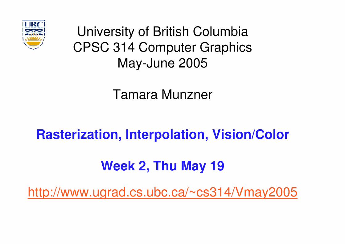
Reading: Today
� FCG Section 2.11 Triangles (Barycentric Coordinates) p 42-46
� FCG Chap 3 Raster Algorithms, p 49-65� except 3.8
� FCG Chap 17 Human Vision, p 293-298 � FCG Chap 18 Color, p 301-311
� until Section 18.9 Tone Mapping
�
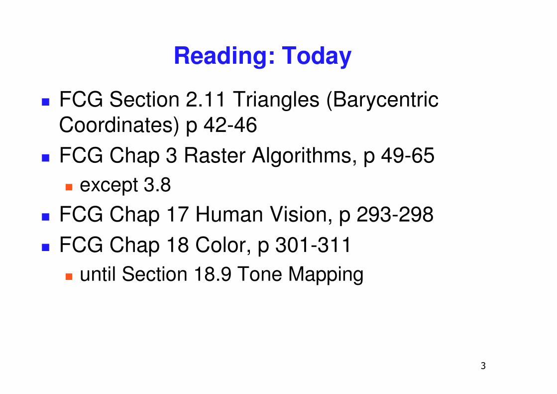
FCG Errata
� p 54 � triangle at bottom of figure shouldn’t have
black outline� p 63
� The test if numbers a [x] and b [y] have the same sign can be implemented as the test ab [xy] > 0.
�
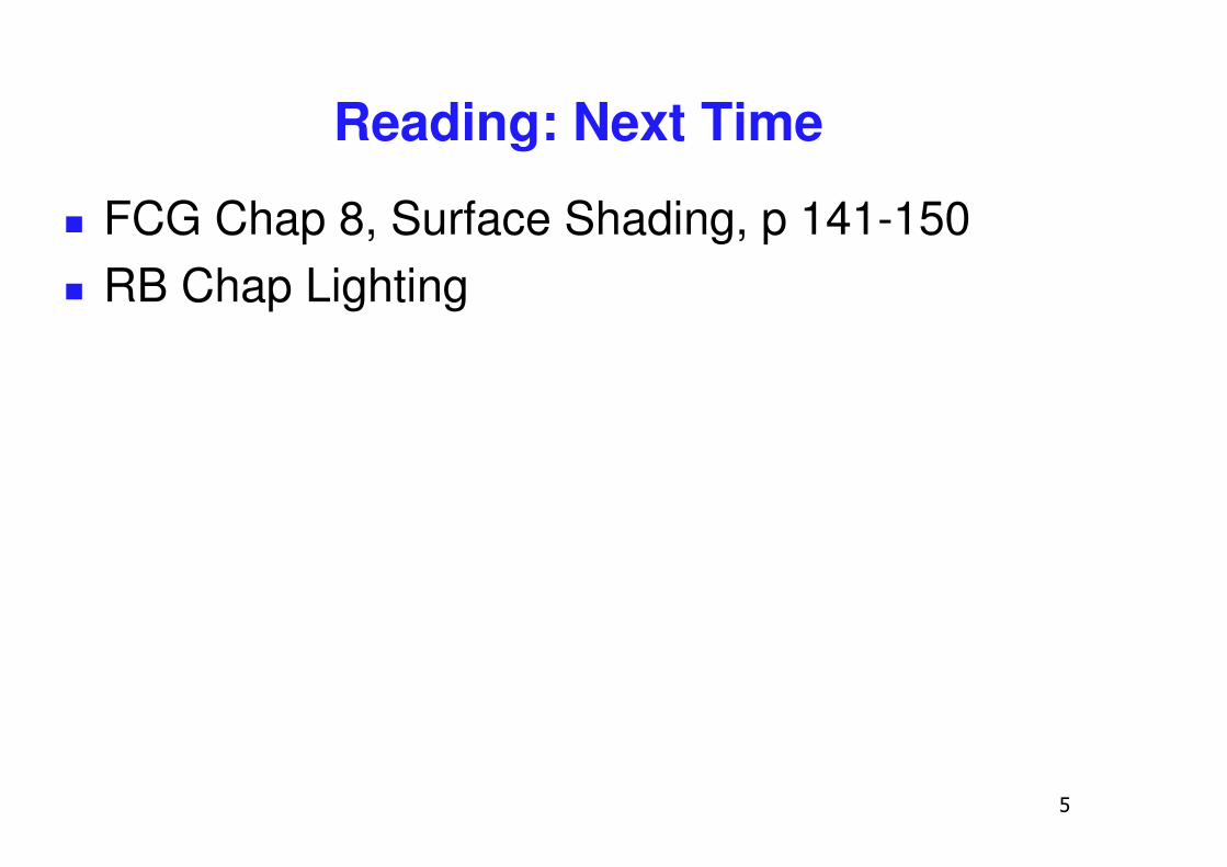
Reading: Next Time
� FCG Chap 8, Surface Shading, p 141-150� RB Chap Lighting
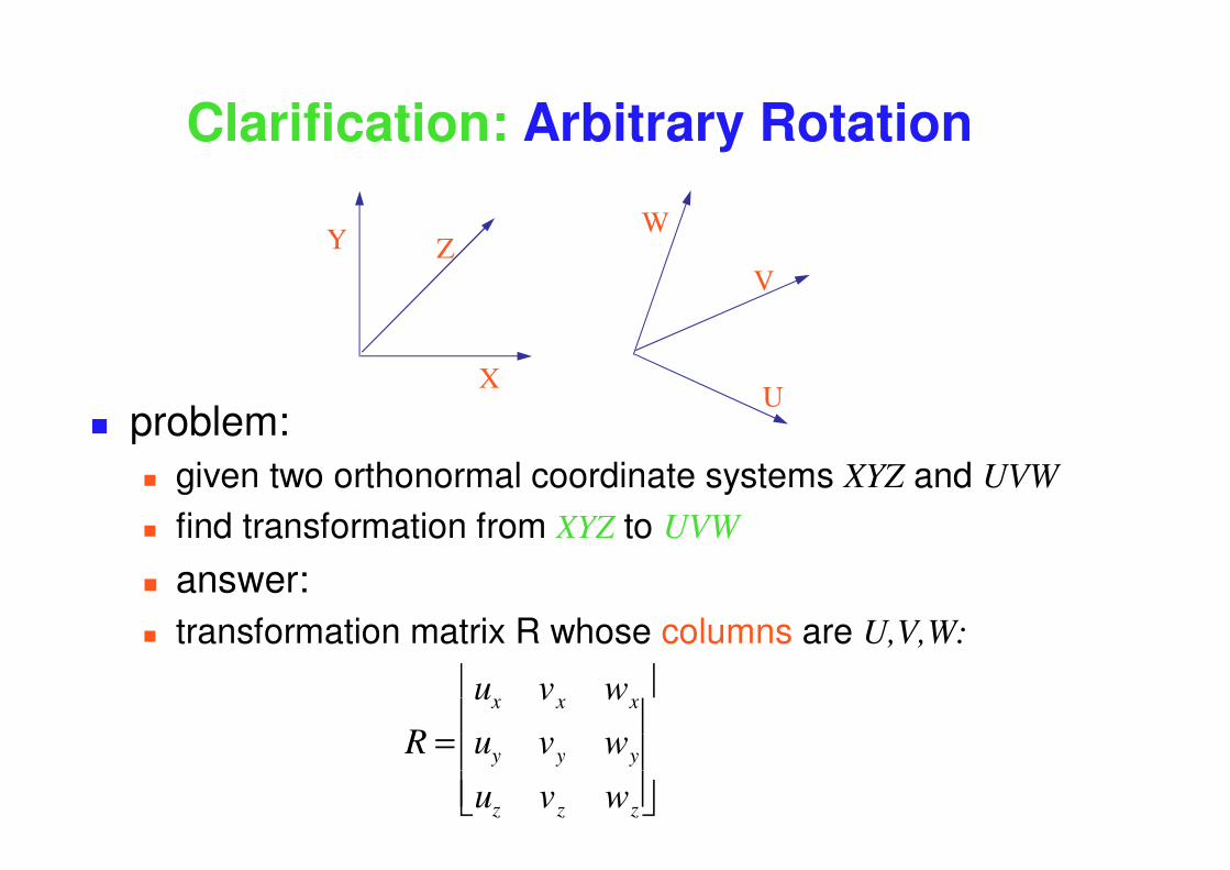
Clarification: Arbitrary Rotation
� problem: � given two orthonormal coordinate systems XYZ and UVW � find transformation from XYZ to UVW
� answer: � transformation matrix R whose columns are U,V,W:
R =ux vx wx
uy vy wy
uz vz wz
�
�
� � �
�
�
� � �
Y Z
X
W
V
U
�
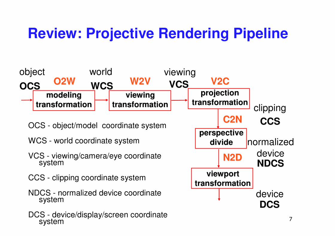
Review: Projective Rendering Pipeline
OCS - object/model coordinate system
WCS - world coordinate system
VCS - viewing/camera/eye coordinate system
CCS - clipping coordinate system
NDCS - normalized device coordinate system
DCS - device/display/screen coordinate system
OCSOCS O2WO2W VCSVCS
CCSCCS
NDCSNDCS
DCSDCS
modelingmodelingtransformationtransformation
viewingviewingtransformationtransformation
projectionprojectiontransformationtransformation
viewportviewporttransformationtransformation
perspectiveperspectivedividedivide
object world viewing
device
normalizeddevice
clipping
W2VW2V V2CV2C
N2DN2D
C2NC2N
WCSWCS
�
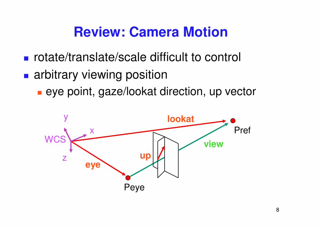
Review: Camera Motion
� rotate/translate/scale difficult to control� arbitrary viewing position
� eye point, gaze/lookat direction, up vector
Peye
Pref
upview
eye
lookaty
z
xWCS
�
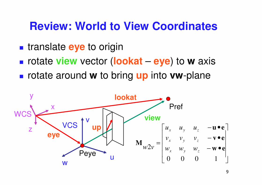
Review: World to View Coordinates
� translate eye to origin� rotate view vector (lookat – eye) to w axis� rotate around w to bring up into vw-plane
y
z
xWCS
v
u
VCS
Peyew
Pref
upview
eye
lookat
����
�
�
����
�
�
•−•−•−
=
1000
2 eweveu
Mzyx
zyx
zyx
www
vvv
uuu
vw
�
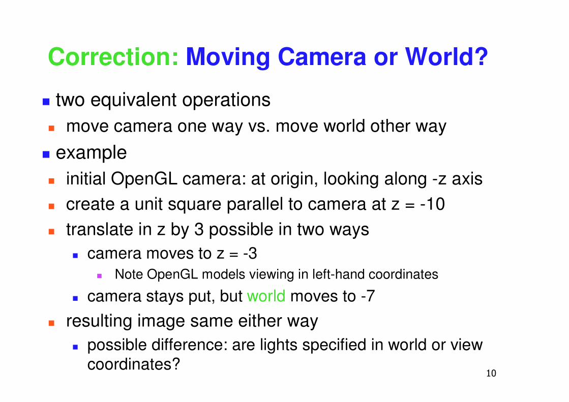
Correction: Moving Camera or World?
� two equivalent operations� move camera one way vs. move world other way
� example� initial OpenGL camera: at origin, looking along -z axis� create a unit square parallel to camera at z = -10� translate in z by 3 possible in two ways
� camera moves to z = -3� Note OpenGL models viewing in left-hand coordinates
� camera stays put, but world moves to -7
� resulting image same either way� possible difference: are lights specified in world or view
coordinates?
��
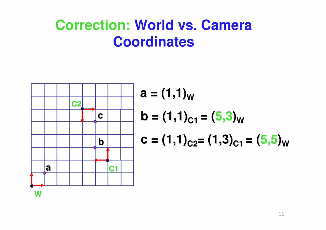
Correction: World vs. Camera Coordinates
WW
aa = = (1,1)(1,1)WW
aa
bb = = (1,1)(1,1)C1 C1 = (= (5,35,3))WW
cc = = (1,1)(1,1)C2C2= = (1,3)(1,3)C1C1 = (= (5,55,5))WW
C1C1
bb
C2C2
cc
��
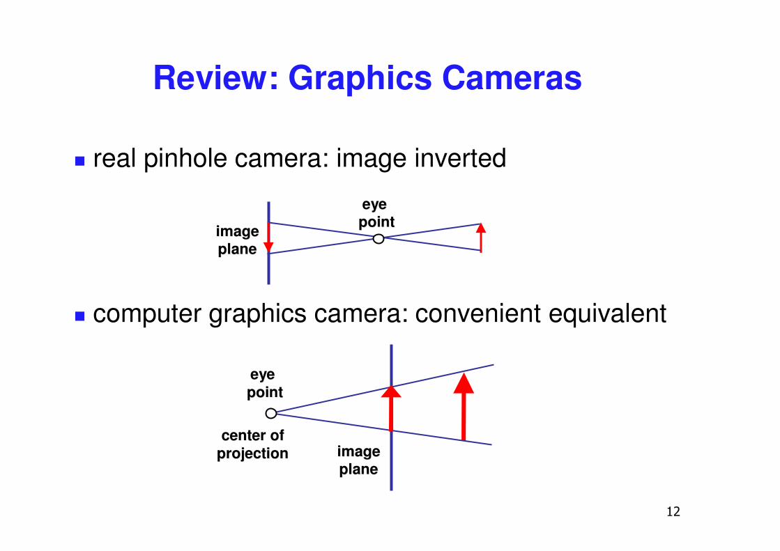
Review: Graphics Cameras
� real pinhole camera: image inverted
imageimageplaneplane
eyeeyepointpoint
� computer graphics camera: convenient equivalent
imageimageplaneplane
eyeeyepointpoint
center ofcenter ofprojectionprojection
��
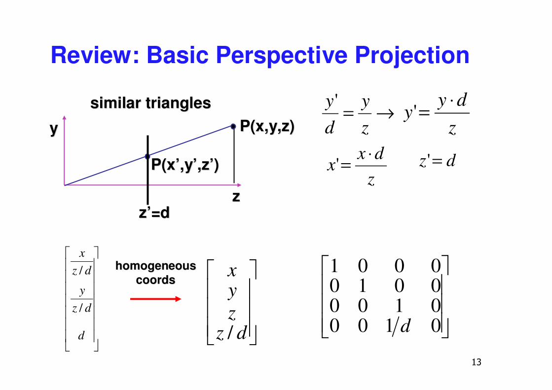
Review: Basic Perspective Projection
similar trianglessimilar triangles →=zy
dy'
zdy
y⋅='
zz
P(x,y,z)P(x,y,z)
P(P(x’x’,,yy’,z’)’,z’)
z’=z’=dd
yy
zdx
x⋅=' dz ='
���
�
�
���
�
�
0100010000100001
d�������
�
�
�������
�
�
d
dzy
dzx
/
/
���
�
�
���
�
�
dzzyx
/
homogeneoushomogeneouscoordscoords
��
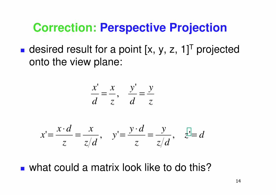
Correction: Perspective Projection
� desired result for a point [x, y, z, 1]T projected onto the view plane:
� what could a matrix look like to do this?
dzdz
yzdy
ydz
xzdx
x
zy
dy
zx
dx
==⋅==⋅=
==
',','
',
'
��
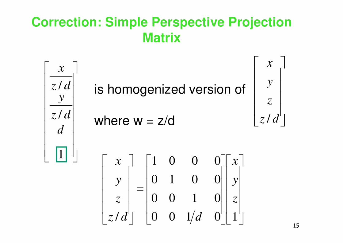
Correction: Simple Perspective Projection Matrix
����
�
�
����
�
�
����
�
�
����
�
�
=
����
�
�
����
�
�
10100010000100001
/z
y
x
ddz
z
y
x�������
�
�
�������
�
�
1
/
/
ddz
ydz
x
is homogenized version of
where w = z/d ����
�
�
����
�
�
dz
z
y
x
/
�
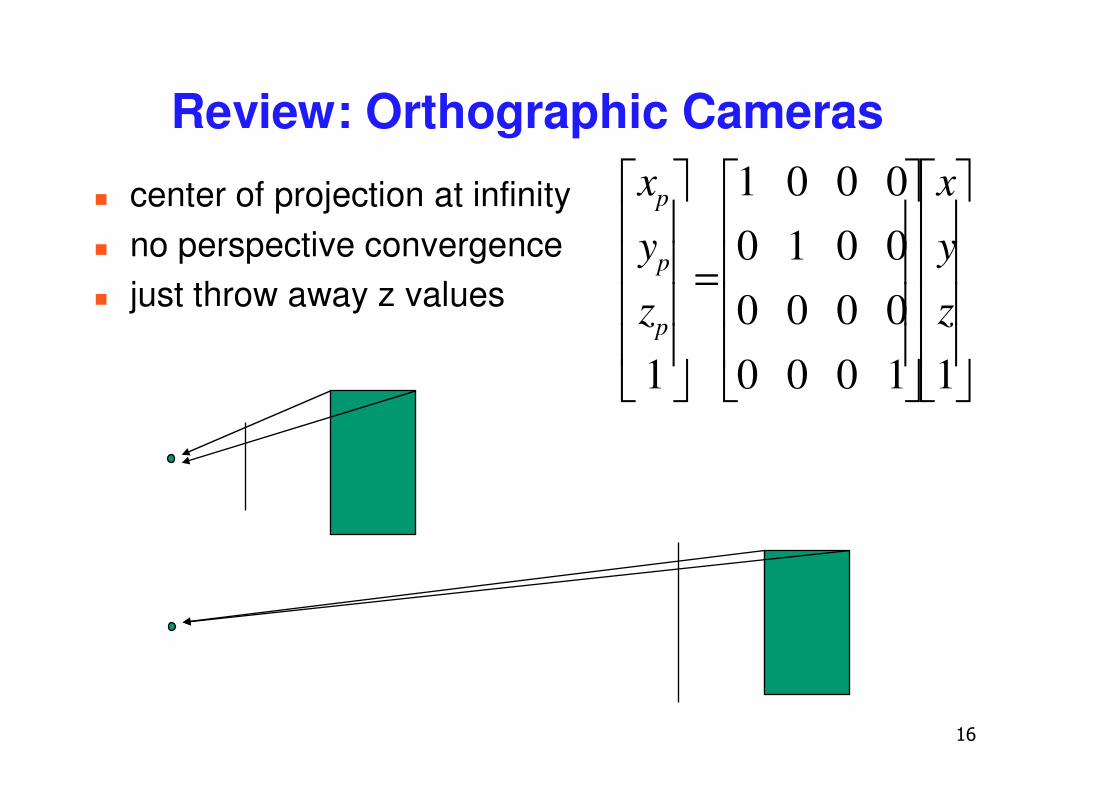
Review: Orthographic Cameras
� center of projection at infinity� no perspective convergence� just throw away z values
����
�
�
����
�
�
����
�
�
����
�
�
=
����
�
�
����
�
�
11000000000100001
1z
y
x
z
y
x
p
p
p
��
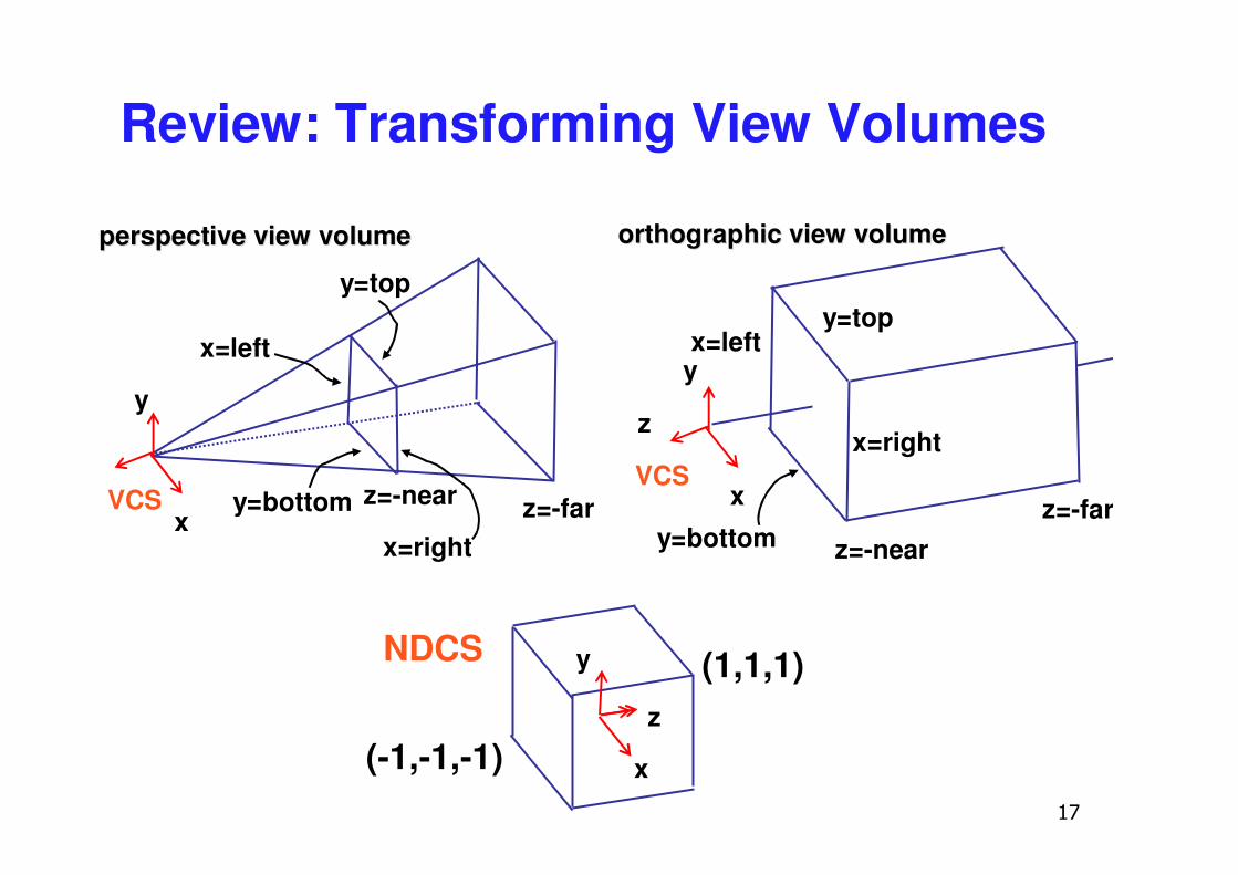
Review: Transforming View Volumes
x
z
NDCS y
(-1,-1,-1)
(1,1,1)
orthographic view volumeorthographic view volume
x
z
VCS
yx=left
y=top
x=right
z=-farz=-neary=bottom
perspective view volumeperspective view volume
x=left
x=right
y=top
y=bottom z=-near z=-farxVCS
y
��
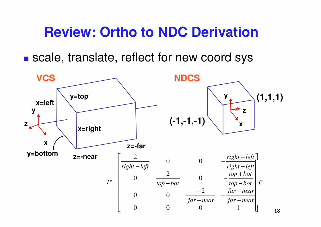
Review: Ortho to NDC Derivation
� scale, translate, reflect for new coord sys
x
z
VCS
yx=left
y=top
x=right
z=-farz=-neary=bottom
x
z
NDCS
y
(-1,-1,-1)
(1,1,1)
P
nearfarnearfar
nearfar
bottopbottop
bottop
leftrightleftright
leftright
P
��������
�
�
��������
�
�
−+−
−−
−+−
−
−+−
−
=
1000
200
02
0
002
'
��
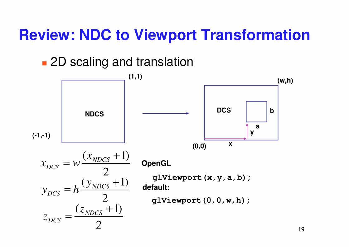
Review: NDC to Viewport Transformation
(-1,-1)
(1,1)(1,1)
(0,0)(0,0)
(w,h)(w,h)
NDCSNDCS DCSDCS
2)1( += NDCS
DCS
xwx
2)1( += NDCS
DCS
yhy
2)1( += NDCS
DCS
zz
glViewport(x,y,a,b);defaultdefault::
aa
bb
xx
yy
glViewport(0,0,w,h);
OpenGLOpenGL
� 2D scaling and translation
�
Clarification: N2V Transformation
� general formulation� translate by
� x offset, width/2� y offset, height/2
� scale by width/height � reflect in y for upper vs. lower left origin� FCG includes additional translation for pixel
centers at (.5, .5) instead of (0,0)� feel free to ignore this
��
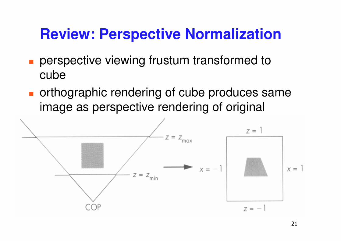
Review: Perspective Normalization
� perspective viewing frustum transformed to cube
� orthographic rendering of cube produces same image as perspective rendering of original frustum
��
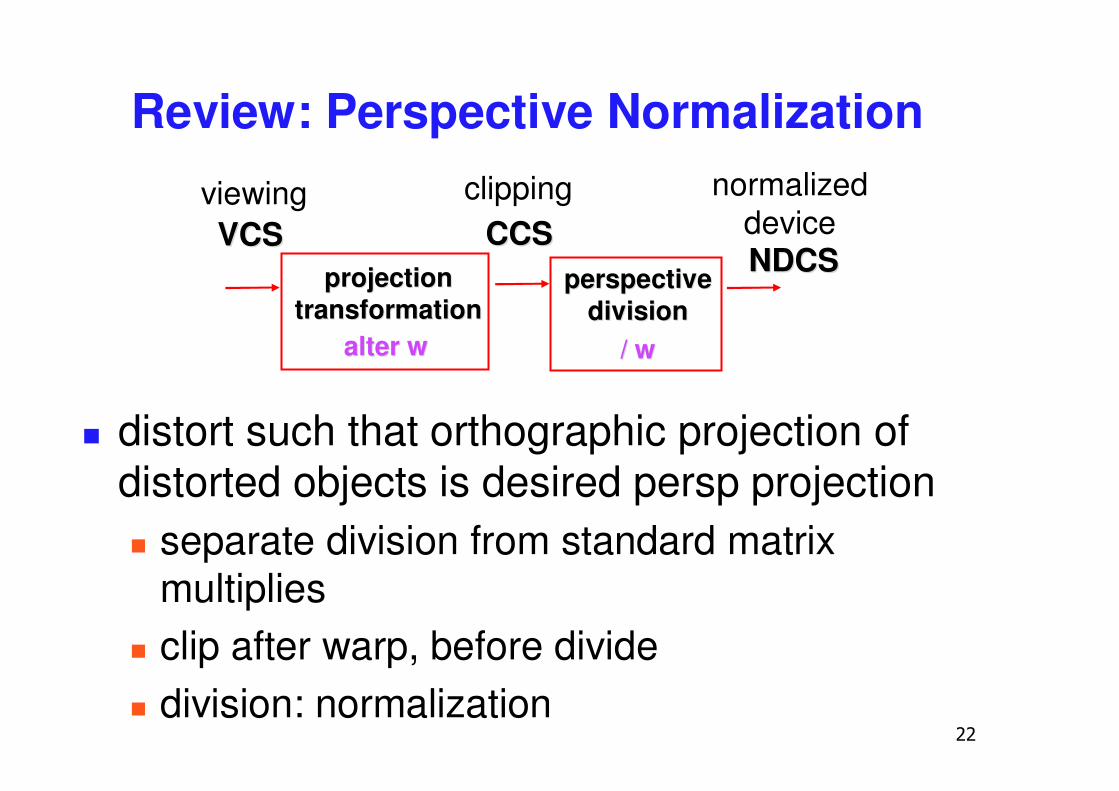
Review: Perspective Normalization
� distort such that orthographic projection of distorted objects is desired persp projection� separate division from standard matrix
multiplies� clip after warp, before divide� division: normalization
CCSCCSNDCSNDCS
alter walter w / w/ w
VCSVCSprojectionprojection
transformationtransformation
viewing normalizeddevice
clipping
perspectiveperspectivedivisiondivision
��
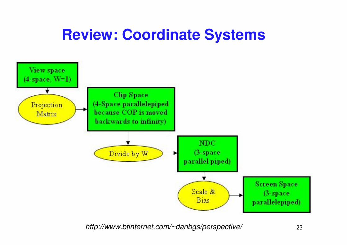
Review: Coordinate Systems
http://www.btinternet.com/~danbgs/perspective/
��
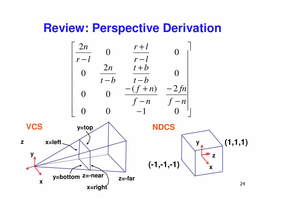
Review: Perspective Derivation
x
z
NDCS
y
(-1,-1,-1)
(1,1,1)x=left
x=right
y=top
y=bottom z=-near z=-farx
VCS
y
z
�������
�
�
�������
�
�
−−
−−+−
−+
−
−+
−
0100
2)(00
02
0
002
nffn
nfnf
btbt
btn
lrlr
lrn
��
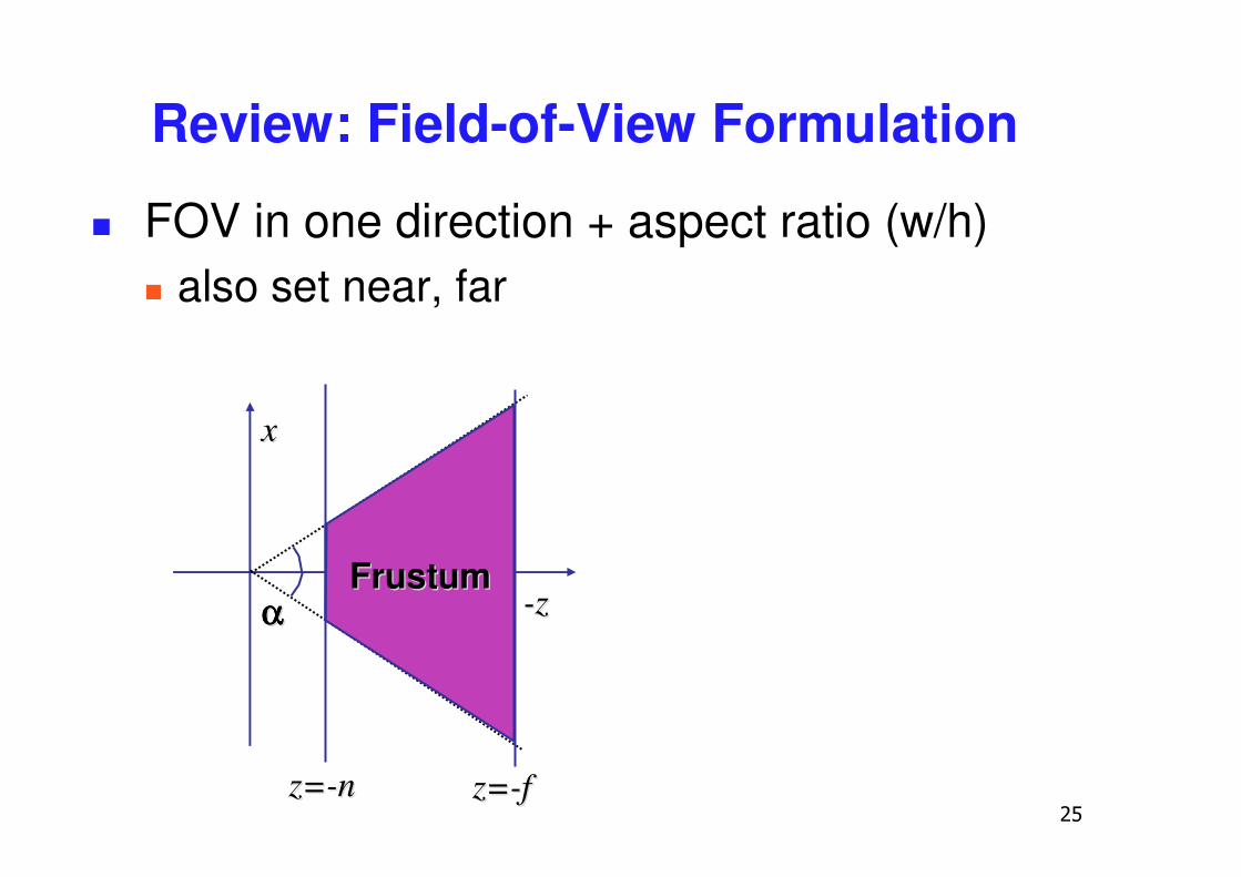
Review: Field-of-View Formulation
� FOV in one direction + aspect ratio (w/h)� also set near, far
--zz
xx
FrustumFrustum
z=z=--nn z=z=--ff
αααααααα
�
Projection Wrapup
��
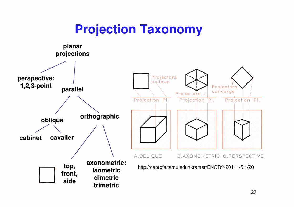
Projection Taxonomyplanarplanar
projectionsprojections
perspective:perspective:1,2,31,2,3--pointpoint parallelparallel
obliqueoblique orthographicorthographic
cabinetcabinet cavaliercavalier
top,top,front,front,sideside
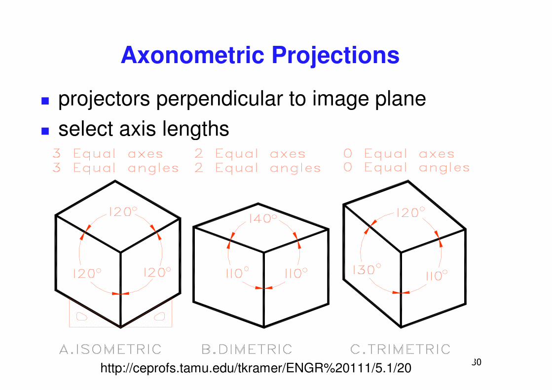
axonometric:axonometric:isometricisometricdimetricdimetrictrimetrictrimetric
http://ceprofs.tamu.edu/tkramer/ENGR%20111/5.1/20
��
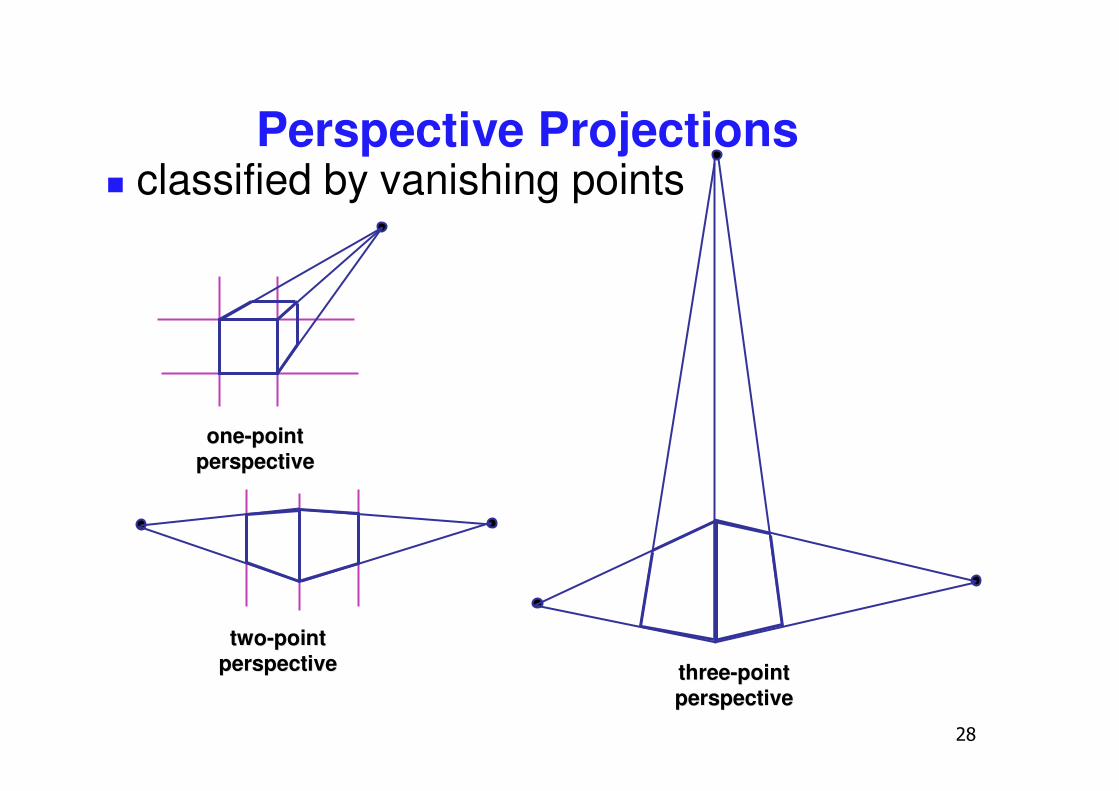
Perspective Projections
oneone--pointpointperspectiveperspective
twotwo--pointpointperspectiveperspective threethree--pointpoint
perspectiveperspective
� classified by vanishing points
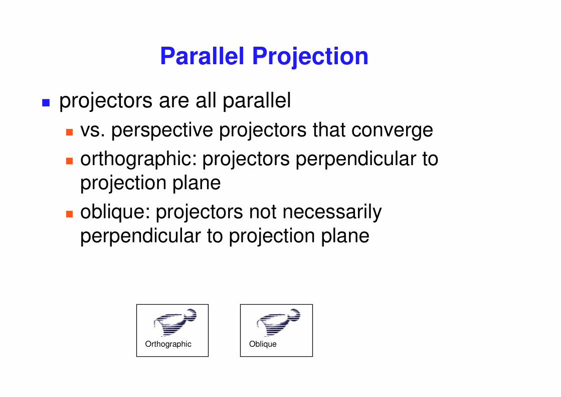
Parallel Projection
� projectors are all parallel� vs. perspective projectors that converge� orthographic: projectors perpendicular to
projection plane� oblique: projectors not necessarily
perpendicular to projection plane
ObliqueOrthographic
�
Axonometric Projections
� projectors perpendicular to image plane� select axis lengths
http://ceprofs.tamu.edu/tkramer/ENGR%20111/5.1/20
��
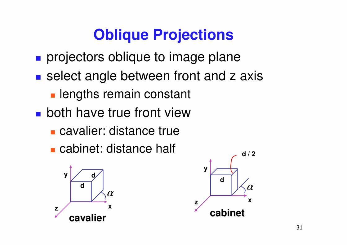
Oblique Projections
xx
yy
zz
α
cavaliercavalier
dddd
xx
yy
zz
α
cabinetcabinet
dd
d / 2d / 2
� projectors oblique to image plane� select angle between front and z axis
� lengths remain constant� both have true front view
� cavalier: distance true� cabinet: distance half
��
Demos
� Tuebingen applets from Frank Hanisch� http://www.gris.uni-tuebingen.de/projects/grdev/doc/html/etc/
AppletIndex.html#Transformationen

��
Rasterization
��
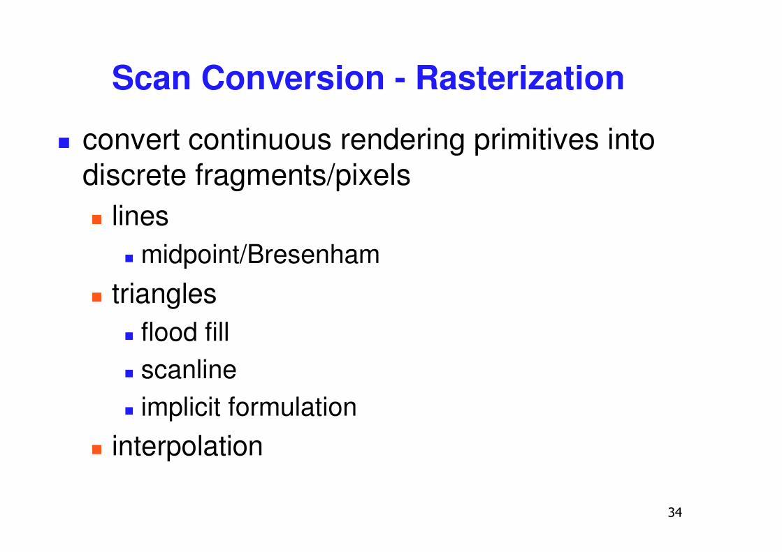
Scan Conversion - Rasterization
� convert continuous rendering primitives into discrete fragments/pixels� lines
� midpoint/Bresenham� triangles
� flood fill� scanline� implicit formulation
� interpolation
��
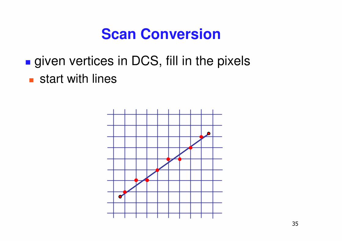
Scan Conversion
� given vertices in DCS, fill in the pixels� start with lines
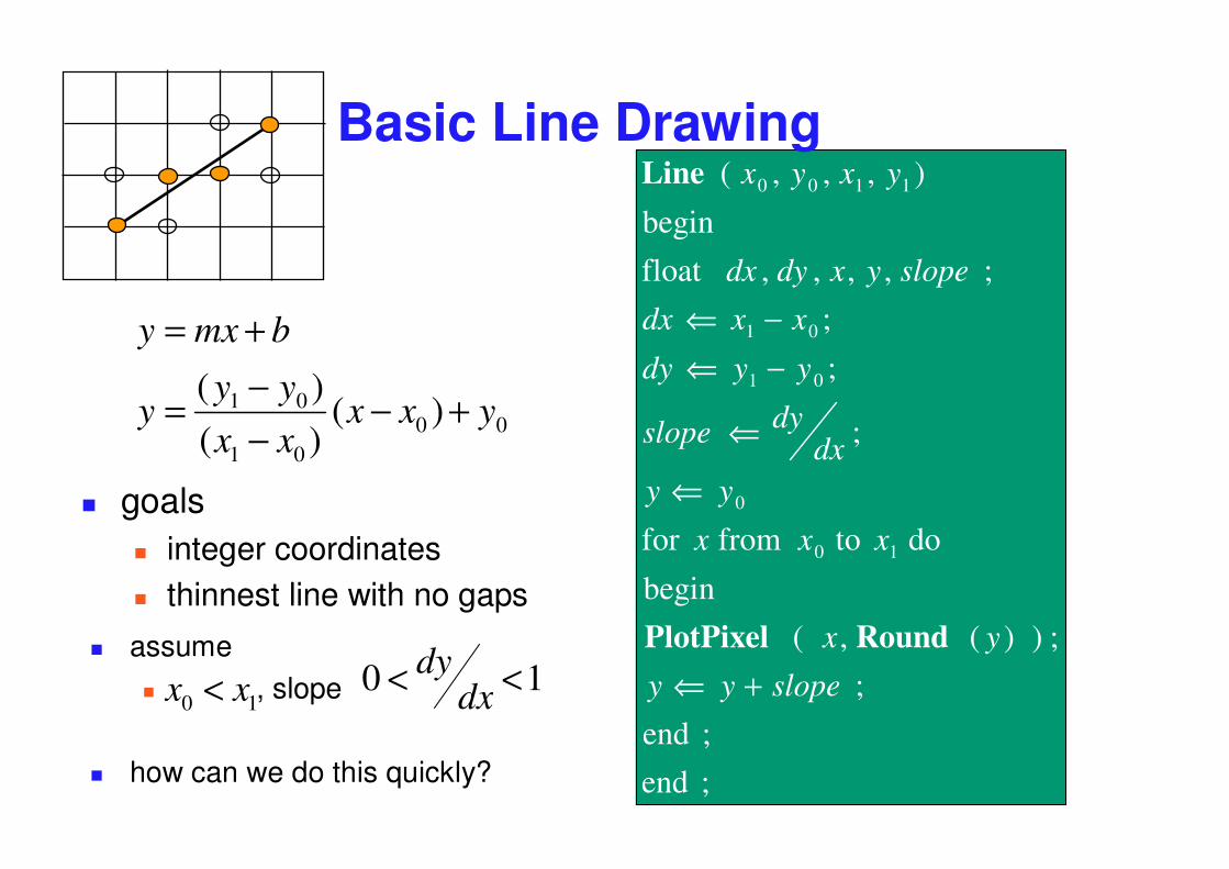
10 xx <
; end; end
; ; ) )( , (
begin
do to from for
;
;
;; , , , ,float
begin
) , , , (
10
0
01
01
1100
slopeyy
yx
xxx
yydx
dyslope
yydy
xxdx
slopeyxdydx
yxyx
+⇐
⇐
⇐
−⇐−⇐
RoundPlotPixel
LineBasic Line Drawing
� assume � , slope
� how can we do this quickly?
� goals� integer coordinates� thinnest line with no gaps
0 < dydx <1
0001
01 )()()(
yxxxxyy
y
bmxy
+−−−=
+=
��
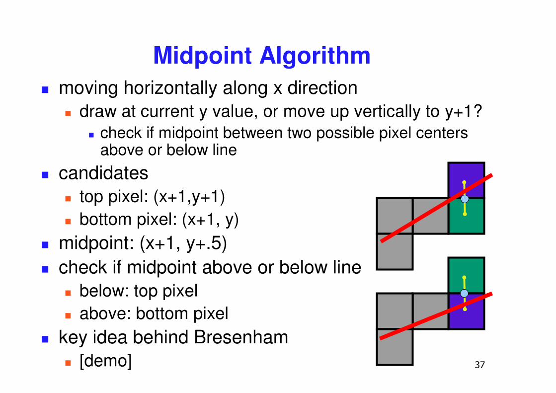
Midpoint Algorithm� moving horizontally along x direction
� draw at current y value, or move up vertically to y+1?� check if midpoint between two possible pixel centers
above or below line� candidates
� top pixel: (x+1,y+1)� bottom pixel: (x+1, y)
� midpoint: (x+1, y+.5)� check if midpoint above or below line
� below: top pixel� above: bottom pixel
� key idea behind Bresenham� [demo]
��
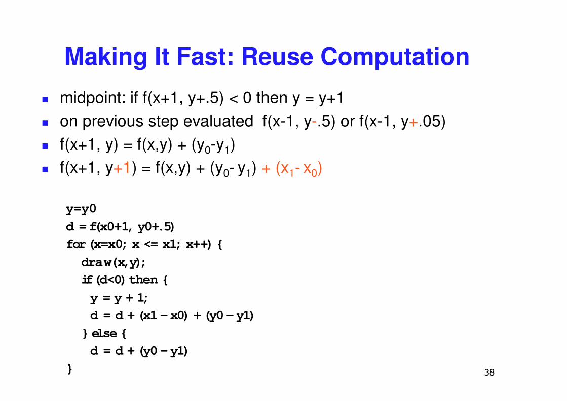
Making It Fast: Reuse Computation� midpoint: if f(x+1, y+.5) < 0 then y = y+1� on previous step evaluated f(x-1, y-.5) or f(x-1, y+.05)� f(x+1, y) = f(x,y) + (y0-y1)� f(x+1, y+1) = f(x,y) + (y0- y1) + (x1- x0)
y=y0d = f(x0+1, y0+.5)for (x=x0; x <= x1; x++) {draw(x,y);if (d<0) then {y = y + 1;d = d + (x1 -x0) + (y0 -y1)
} else {d = d + (y0 -y1)
}
��
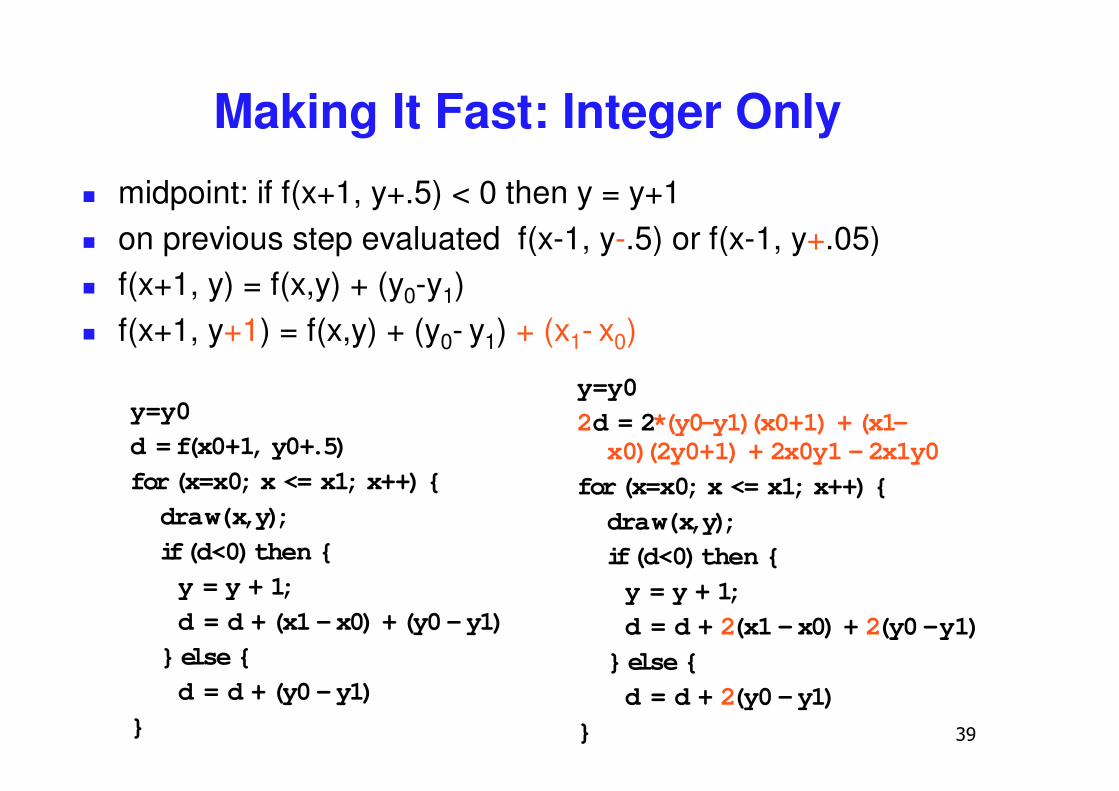
Making It Fast: Integer Only� midpoint: if f(x+1, y+.5) < 0 then y = y+1� on previous step evaluated f(x-1, y-.5) or f(x-1, y+.05)� f(x+1, y) = f(x,y) + (y0-y1)� f(x+1, y+1) = f(x,y) + (y0- y1) + (x1- x0)
y=y0d = f(x0+1, y0+.5)for (x=x0; x <= x1; x++) {draw(x,y);if (d<0) then {y = y + 1;d = d + (x1 -x0) + (y0 -y1)
} else {d = d + (y0 -y1)
}
y=y02d = 2*(y0-y1)(x0+1) + (x1-x0)(2y0+1) + 2x0y1 -2x1y0
for (x=x0; x <= x1; x++) {draw(x,y);if (d<0) then {y = y + 1;d = d + 2(x1 -x0) + 2(y0 -y1)
} else {d = d + 2(y0 -y1)
}
�
Rasterizing Polygons/Triangles
� basic surface representation in rendering� why?
� lowest common denominator� can approximate any surface with arbitrary accuracy
� all polygons can be broken up into triangles
� guaranteed to be:� planar� triangles - convex
� simple to render� can implement in hardware
��
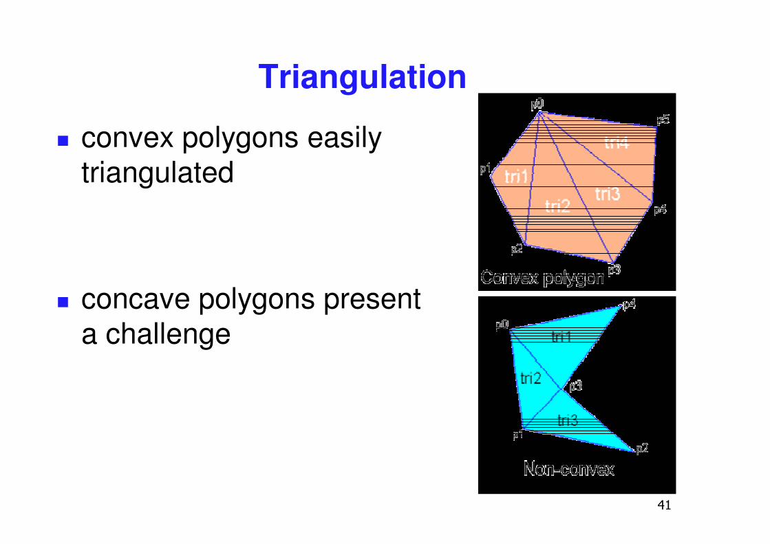
Triangulation
� convex polygons easily triangulated
� concave polygons present a challenge
��
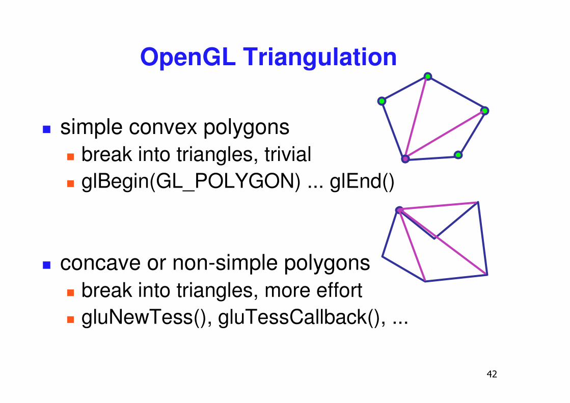
OpenGL Triangulation
� simple convex polygons� break into triangles, trivial� glBegin(GL_POLYGON) ... glEnd()
� concave or non-simple polygons� break into triangles, more effort� gluNewTess(), gluTessCallback(), ...
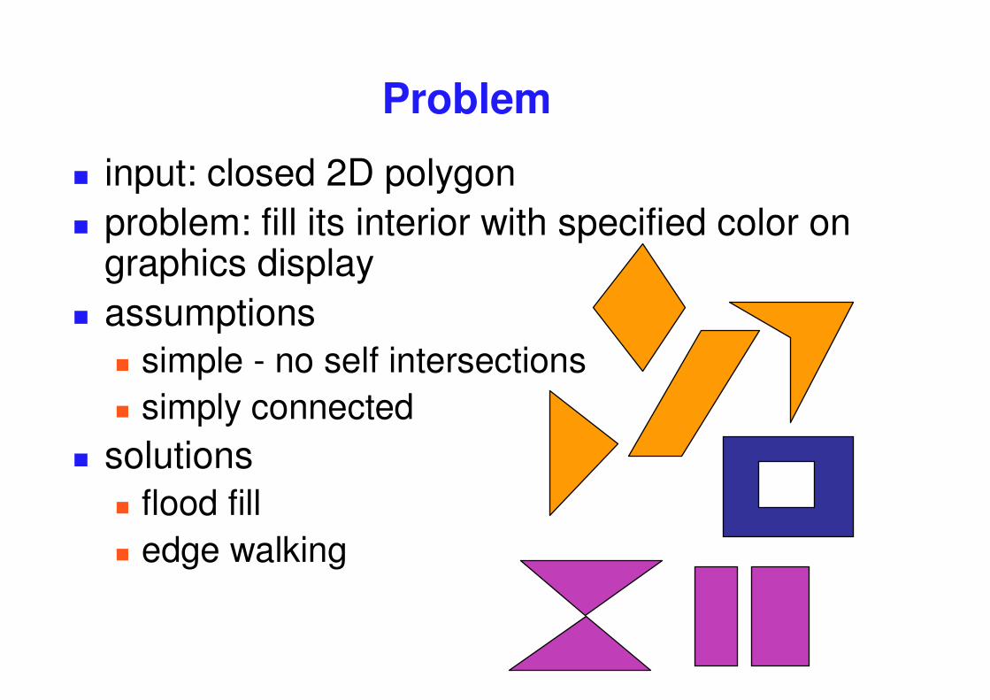
Problem
� input: closed 2D polygon� problem: fill its interior with specified color on
graphics display� assumptions
� simple - no self intersections� simply connected
� solutions� flood fill� edge walking
��
P
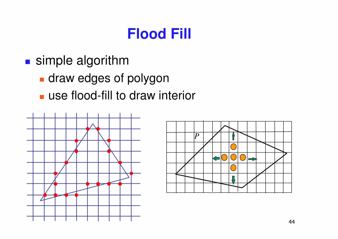
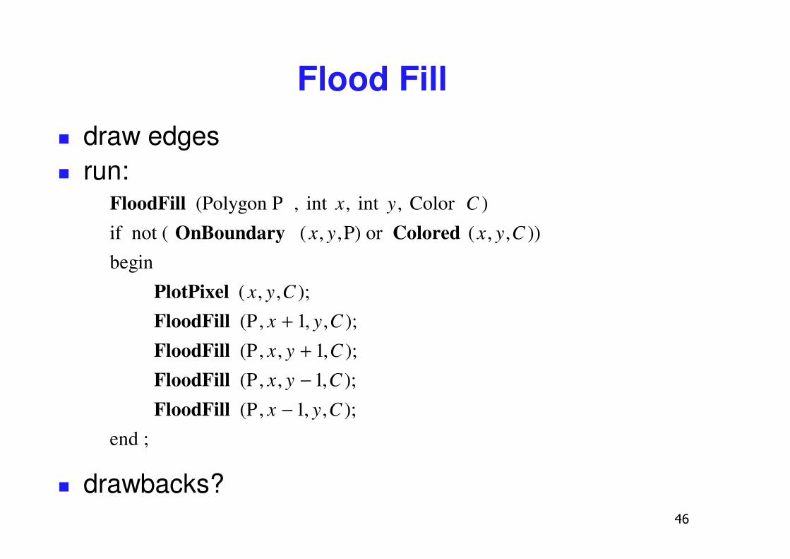
Flood Fill
� simple algorithm� draw edges of polygon� use flood-fill to draw interior
��
Flood Fill
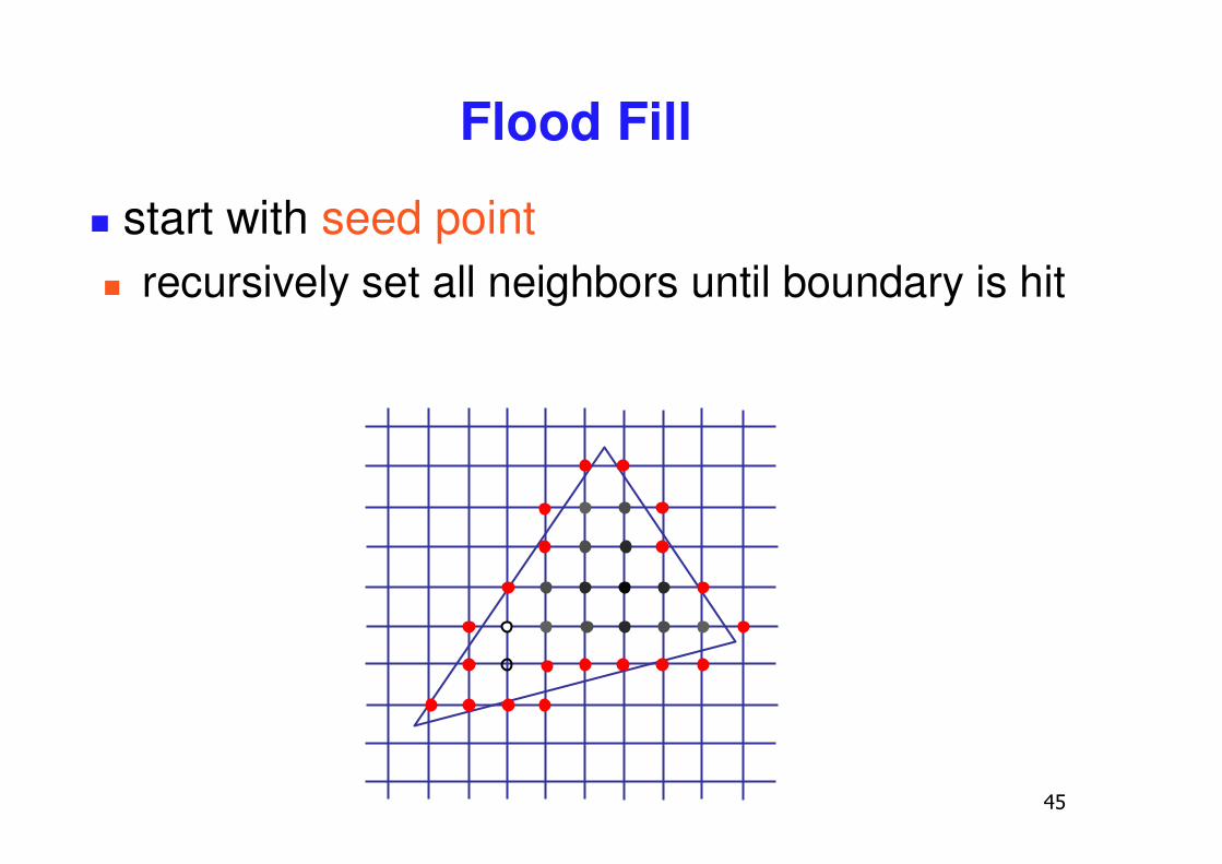
� start with seed point� recursively set all neighbors until boundary is hit
�
FloodFill (Polygon P , int x, int y, Color C )
if not ( OnBoundary ( x, y,P) or Colored ( x, y,C )) begin
PlotPixel ( x, y,C );FloodFill (P, x + 1, y,C );
FloodFill (P, x, y + 1,C );FloodFill (P, x, y − 1,C );
FloodFill (P, x − 1, y,C );end ;
Flood Fill� draw edges� run:
� drawbacks?
��
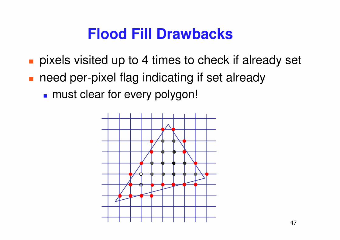
Flood Fill Drawbacks
� pixels visited up to 4 times to check if already set� need per-pixel flag indicating if set already
� must clear for every polygon!
��
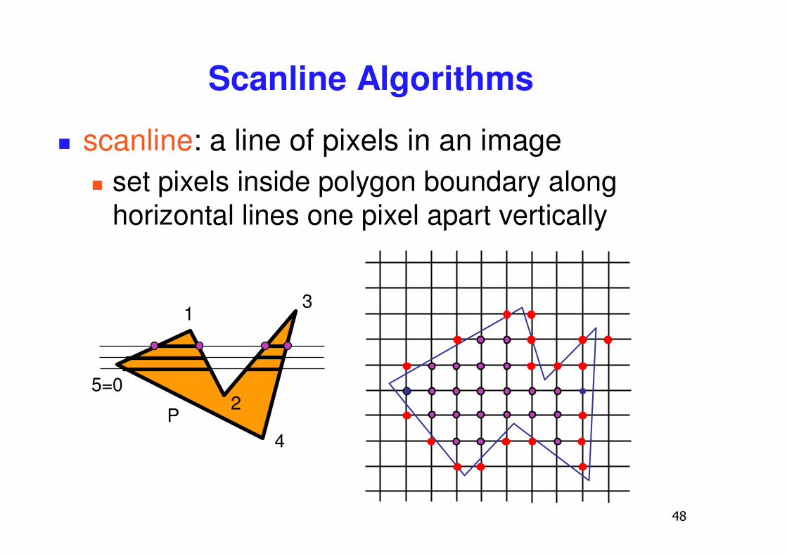
Scanline Algorithms
� scanline: a line of pixels in an image� set pixels inside polygon boundary along
horizontal lines one pixel apart vertically
1
2
3
4
5=0
P
��
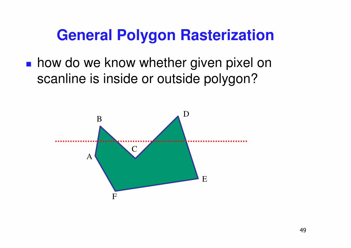
General Polygon Rasterization
� how do we know whether given pixel on scanline is inside or outside polygon?
A
B
C
D
E
F
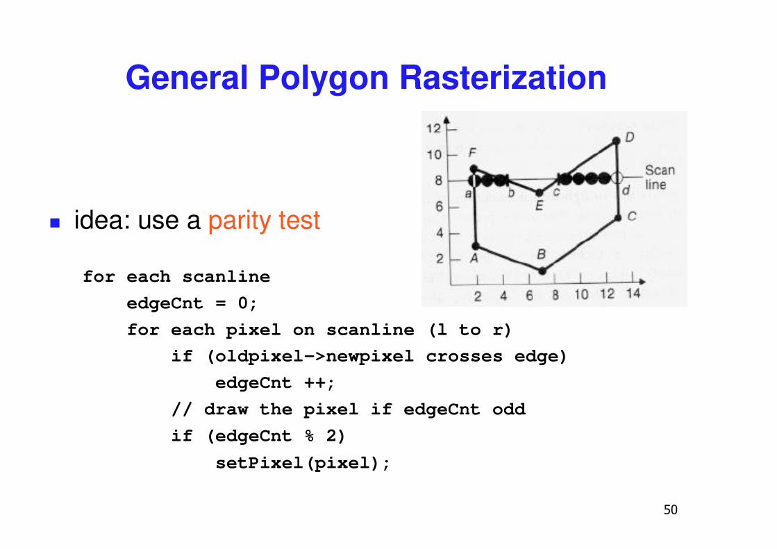
�
General Polygon Rasterization
� idea: use a parity test
for each scanlineedgeCnt = 0;for each pixel on scanline (l to r)
if (oldpixel->newpixel crosses edge) edgeCnt ++;
// draw the pixel if edgeCnt oddif (edgeCnt % 2)
setPixel(pixel);
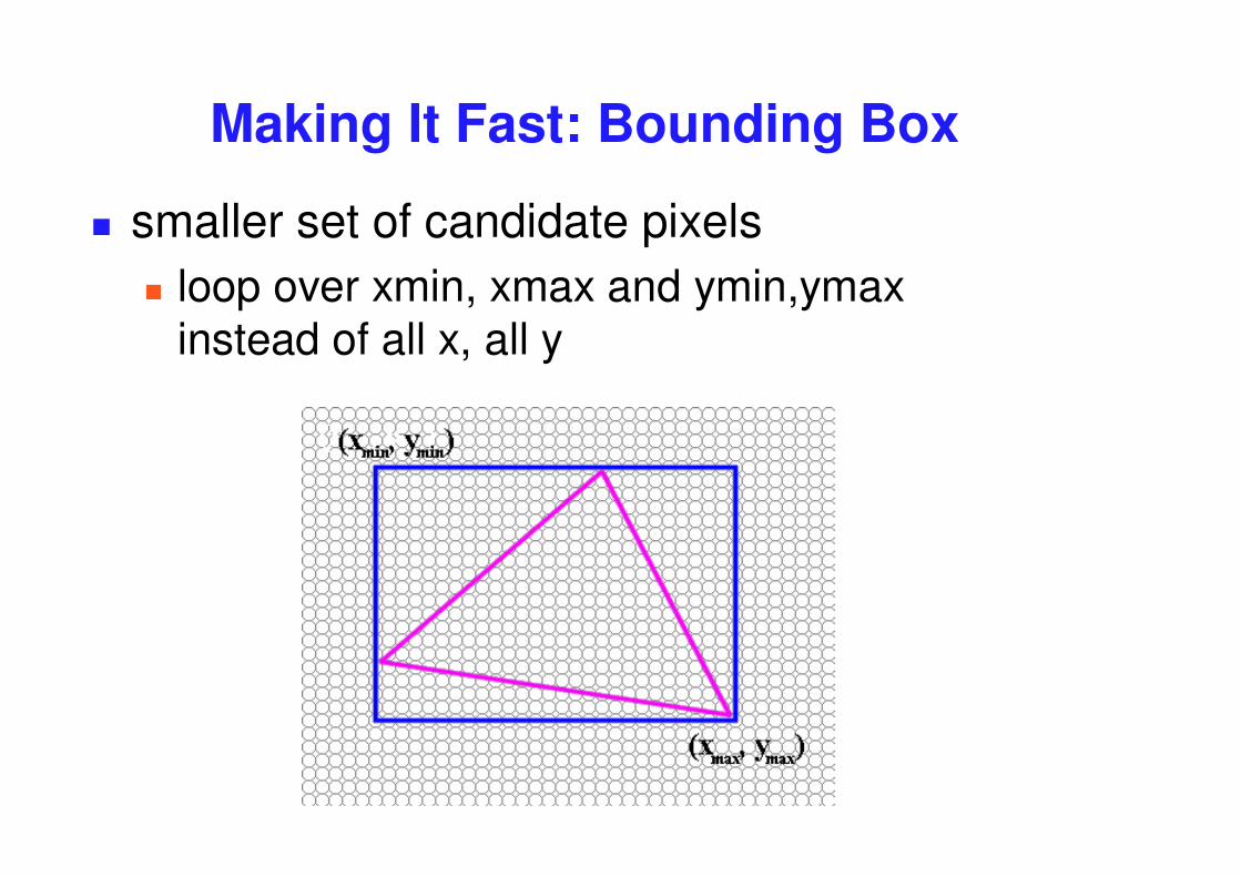
Making It Fast: Bounding Box
� smaller set of candidate pixels� loop over xmin, xmax and ymin,ymax
instead of all x, all y
��
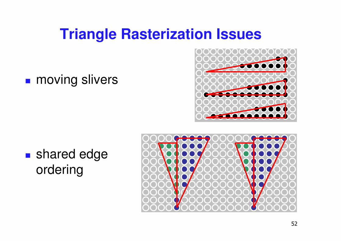
� moving slivers
� shared edge ordering
Triangle Rasterization Issues
��
Triangle Rasterization Issues
� exactly which pixels should be lit?� pixels with centers inside triangle edges
� what about pixels exactly on edge?� draw them: order of triangles matters (it shouldn’t)� don’t draw them: gaps possible between triangles
� need a consistent (if arbitrary) rule � example: draw pixels on left or top edge, but not
on right or bottom edge� example: check if triangle on same side of edge as
offscreen point
��
Interpolation

��
zyx NNN ,,
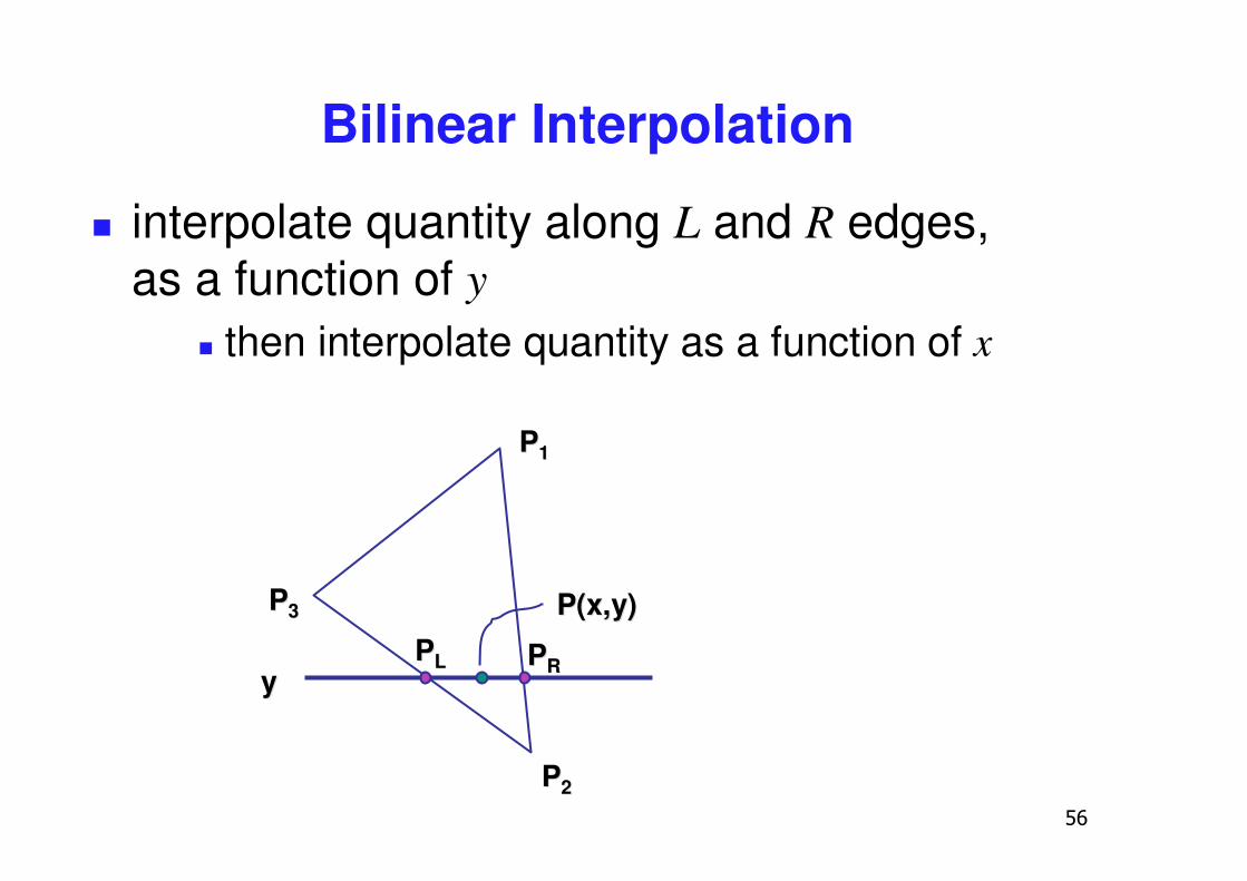
Interpolation During Scan Conversion
� drawing pixels in polygon requires interpolating values between vertices � z values� r,g,b colour components
� use for Gouraud shading� u,v texture coordinates� surface normals
� equivalent methods (for triangles)� bilinear interpolation� barycentric coordinates
�
Bilinear Interpolation
� interpolate quantity along L and R edges, as a function of y
� then interpolate quantity as a function of x
yy
P(x,y)P(x,y)
PP11
PP22
PP33
PPLL PPRR
��
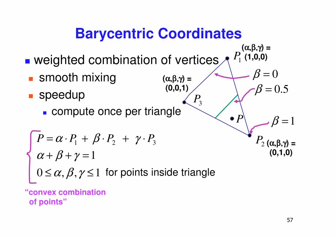
Barycentric Coordinates
� weighted combination of vertices� smooth mixing� speedup
� compute once per triangle
1P
3P
2P
P
((α,β,γα,β,γα,β,γα,β,γα,β,γα,β,γα,β,γα,β,γ) =) =((1,0,0)1,0,0)
((α,β,γα,β,γα,β,γα,β,γα,β,γα,β,γα,β,γα,β,γ) =) =((0,1,0)0,1,0)
((α,β,γα,β,γα,β,γα,β,γα,β,γα,β,γα,β,γα,β,γ) =) =((0,0,1)0,0,1) 5.0=β
1=β
0=β
321 PPPP ⋅+⋅+⋅= γβα
1,,01
≤≤=++
γβαγβα
““convex combinationconvex combinationof points”of points”
for points inside triangle
��
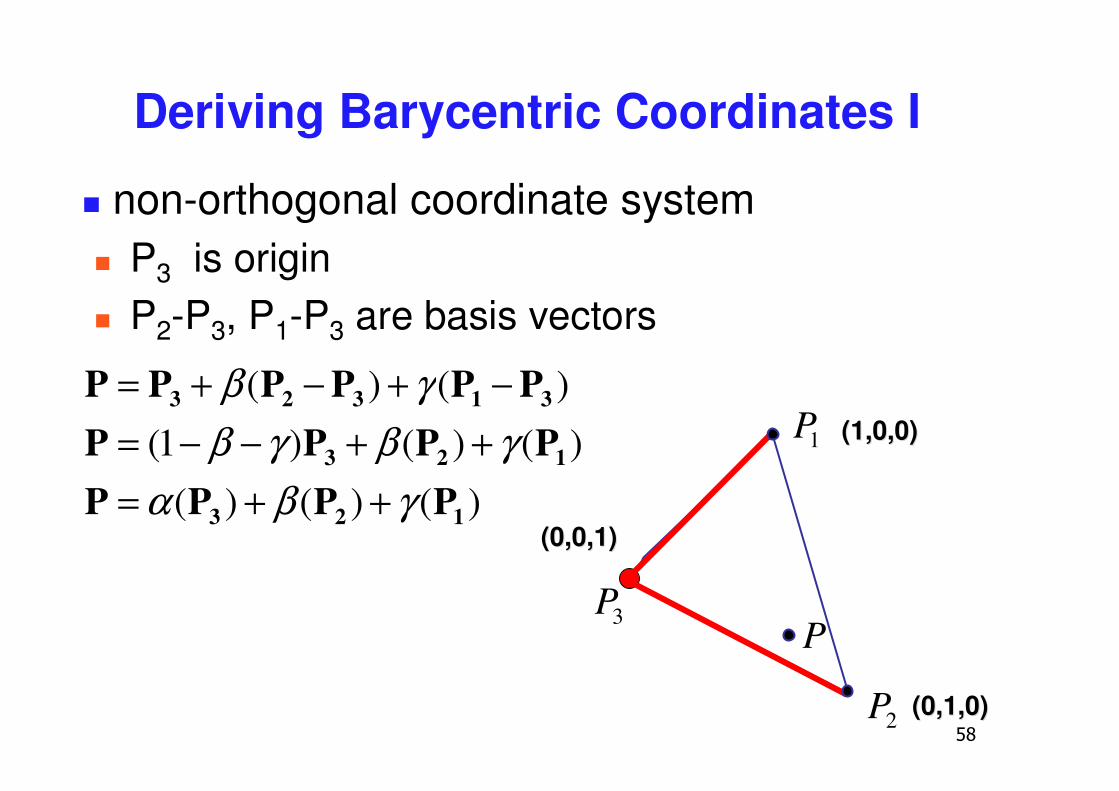
Deriving Barycentric Coordinates I
� non-orthogonal coordinate system� P3 is origin� P2-P3, P1-P3 are basis vectors
1P
3P
2P
P
(1,0,0)(1,0,0)
(0,1,0)(0,1,0)
(0,0,1)(0,0,1))()()(
)()()1(
)()(
123
123
31323
PPPPPPPP
PPPPPP
γβαγβγβ
γβ
++=++−−=
−+−+=
��
PP22
PP33
PP11
PPLL PPRRPPdd22
: d: d
11
321
12
21
2
321
12
21
1
2321
12
)1(
)(
Pdd
dP
ddd
Pdd
dP
ddd
PPdd
dPPL
++
+=
=+
++
−=
−+
+=
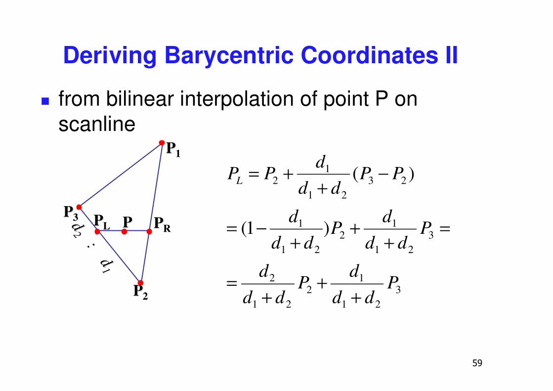
Deriving Barycentric Coordinates II
� from bilinear interpolation of point P onscanline

Deriving Barycentric Coordinates II
� similarly
bb 11:
b:
b22
PP22
PP33
PP11
PPLL PPRRPPdd22
: d: d
11
121
12
21
2
121
12
21
1
2121
12
)1(
)(
Pbb
bP
bbb
Pbb
bP
bbb
PPbb
bPPR
++
+=
=+
++
−=
−+
+=
�
RL Pcc
cP
ccc
P ⋅+
+⋅+
=21
1
21
2
bb 11:
b:
b22
PP22
PP33
PP11
PPLL PPRRPPdd22
: d: d
11
321
12
21
2 Pdd
dP
ddd
PL ++
+=
121
12
21
2 Pbb
bP
bbb
PR ++
+=cc11: c: c22
���
�
�
++
+++���
�
�
++
++= 1
21
12
21
2
21
13
21
12
21
2
21
2 Pbb
bP
bbb
ccc
Pdd
dP
ddd
ccc
P
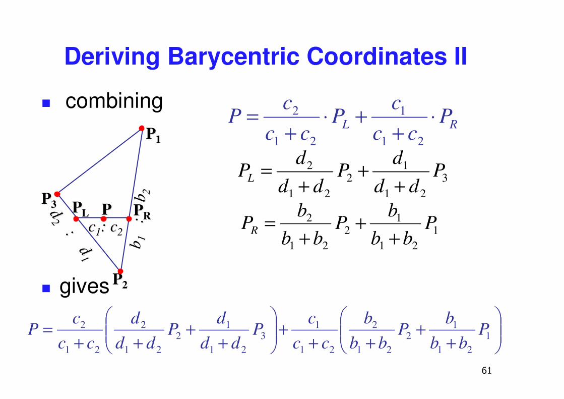
Deriving Barycentric Coordinates II
� combining
� gives
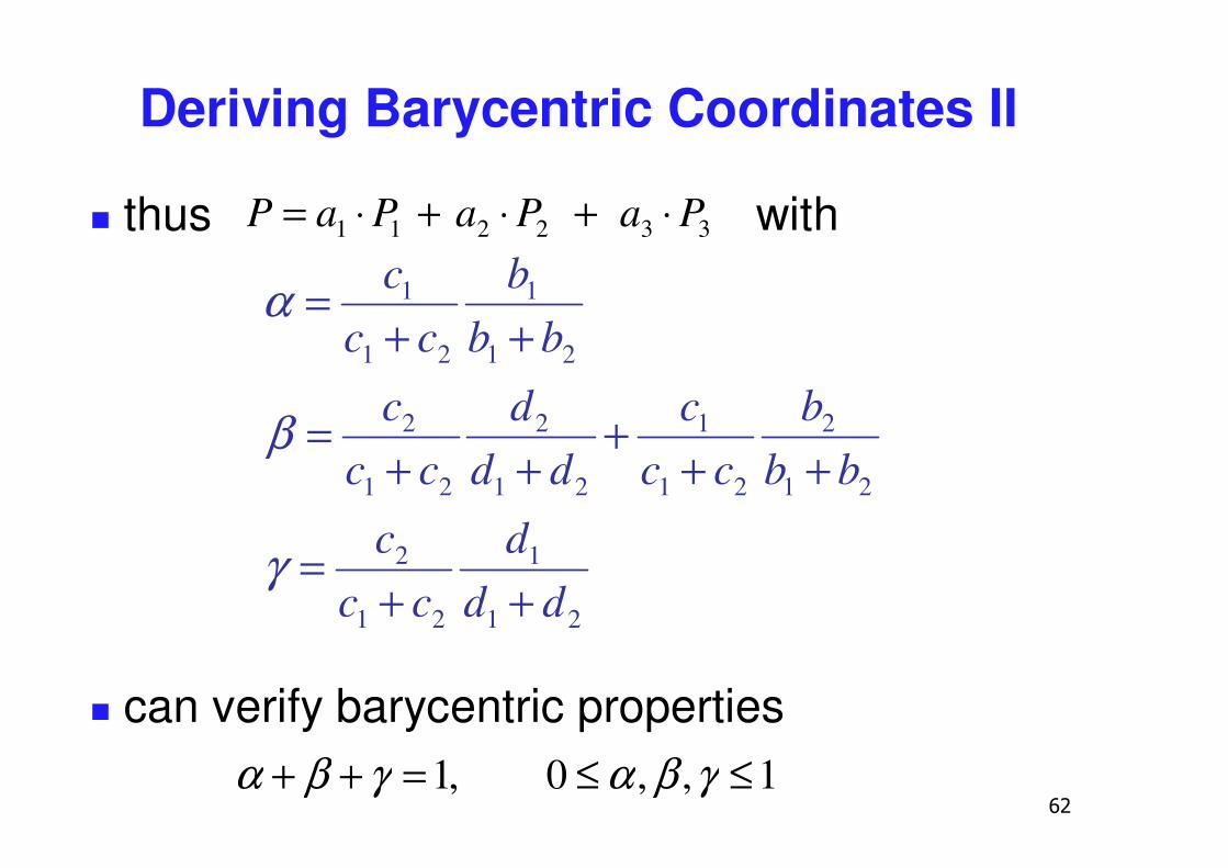
�
Deriving Barycentric Coordinates II
� thus with
� can verify barycentric properties
332211 PaPaPaP ⋅+⋅+⋅=
21
1
21
2
21
2
21
1
21
2
21
2
21
1
21
1
ddd
ccc
bbb
ccc
ddd
ccc
bbb
ccc
++=
+++
++=
++=
γ
β
α
1,,0,1 ≤≤=++ γβαγβα
�
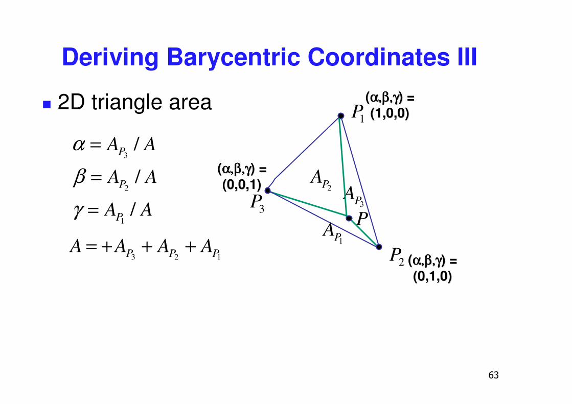
Deriving Barycentric Coordinates III
� 2D triangle area
3PA
1P
3P
2P
P
((α,β,γα,β,γα,β,γα,β,γα,β,γα,β,γα,β,γα,β,γ) =) =((1,0,0)1,0,0)
((α,β,γα,β,γα,β,γα,β,γα,β,γα,β,γα,β,γα,β,γ) =) =((0,1,0)0,1,0)
((α,β,γα,β,γα,β,γα,β,γα,β,γα,β,γα,β,γα,β,γ) =) =((0,0,1)0,0,1)
AA
AA
AA
P
P
P
/
/
/
1
2
3
=
=
=
γβα
2PA
1PA123 PPP AAAA +++=
�
Vision/Color
�
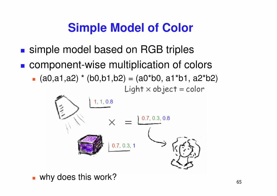
Simple Model of Color
� simple model based on RGB triples� component-wise multiplication of colors
� (a0,a1,a2) * (b0,b1,b2) = (a0*b0, a1*b1, a2*b2)
� why does this work?
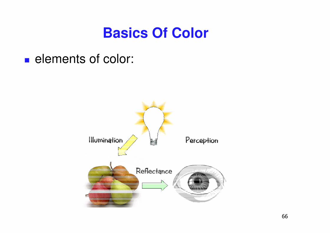
Basics Of Color
� elements of color:
�
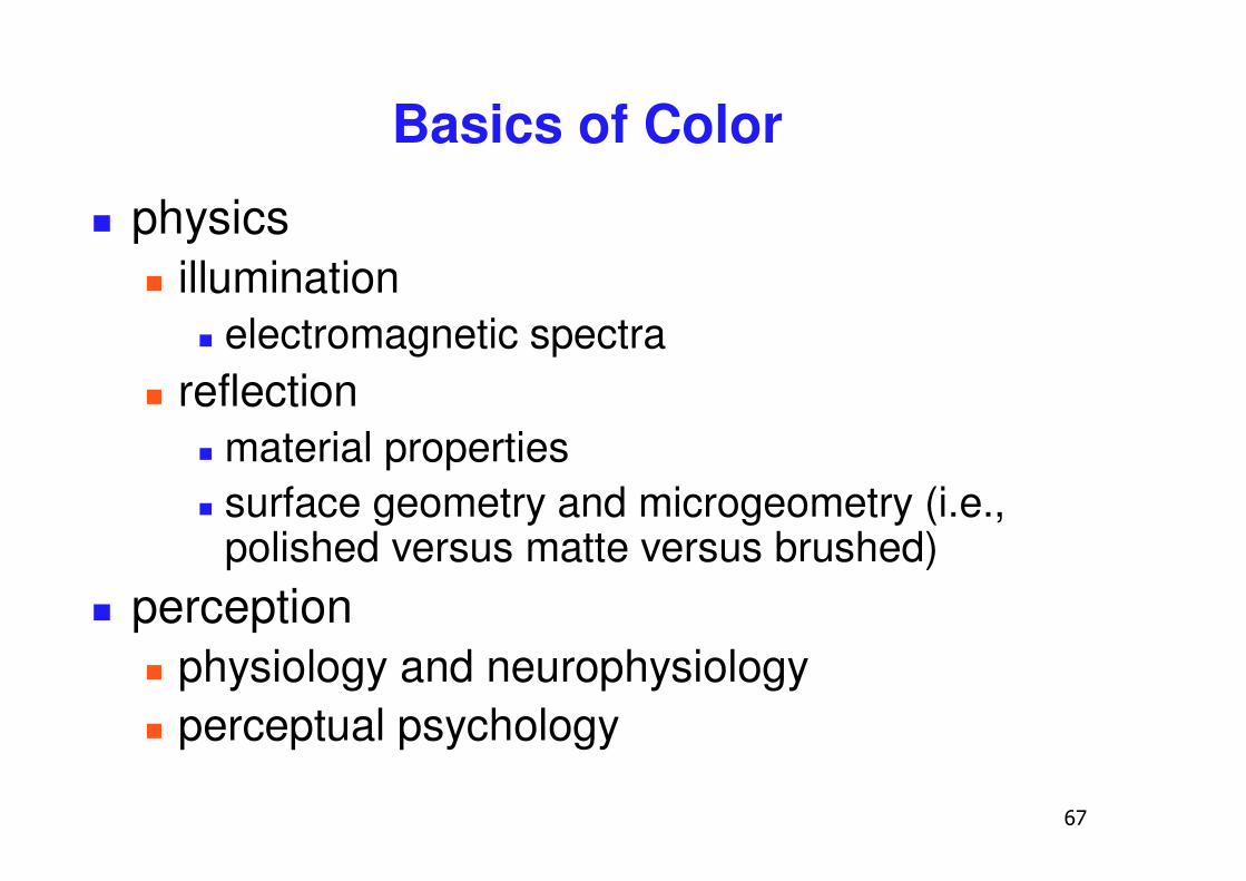
Basics of Color
� physics� illumination
� electromagnetic spectra� reflection
� material properties� surface geometry and microgeometry (i.e.,
polished versus matte versus brushed)� perception
� physiology and neurophysiology� perceptual psychology
�
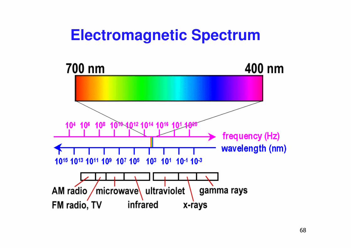
Electromagnetic Spectrum
�
White Light
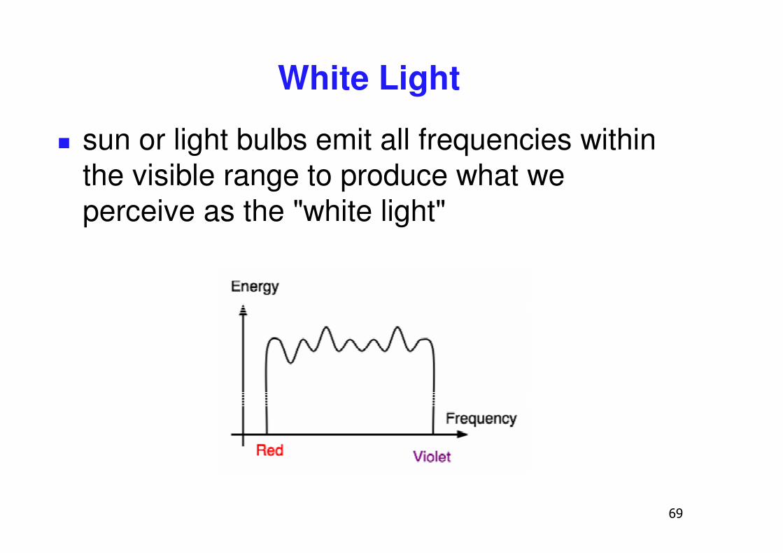
� sun or light bulbs emit all frequencies within the visible range to produce what we perceive as the "white light"
�
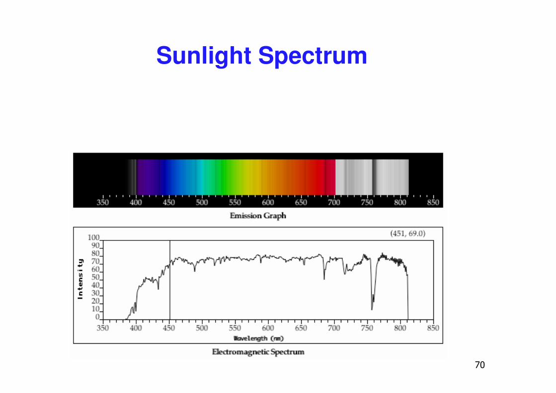
Sunlight Spectrum
��
White Light and Color
� when white light is incident upon an object, some frequencies are reflected and some are absorbed by the object
� combination of frequencies present in the reflected light that determinses what we perceive as the color of the object
��
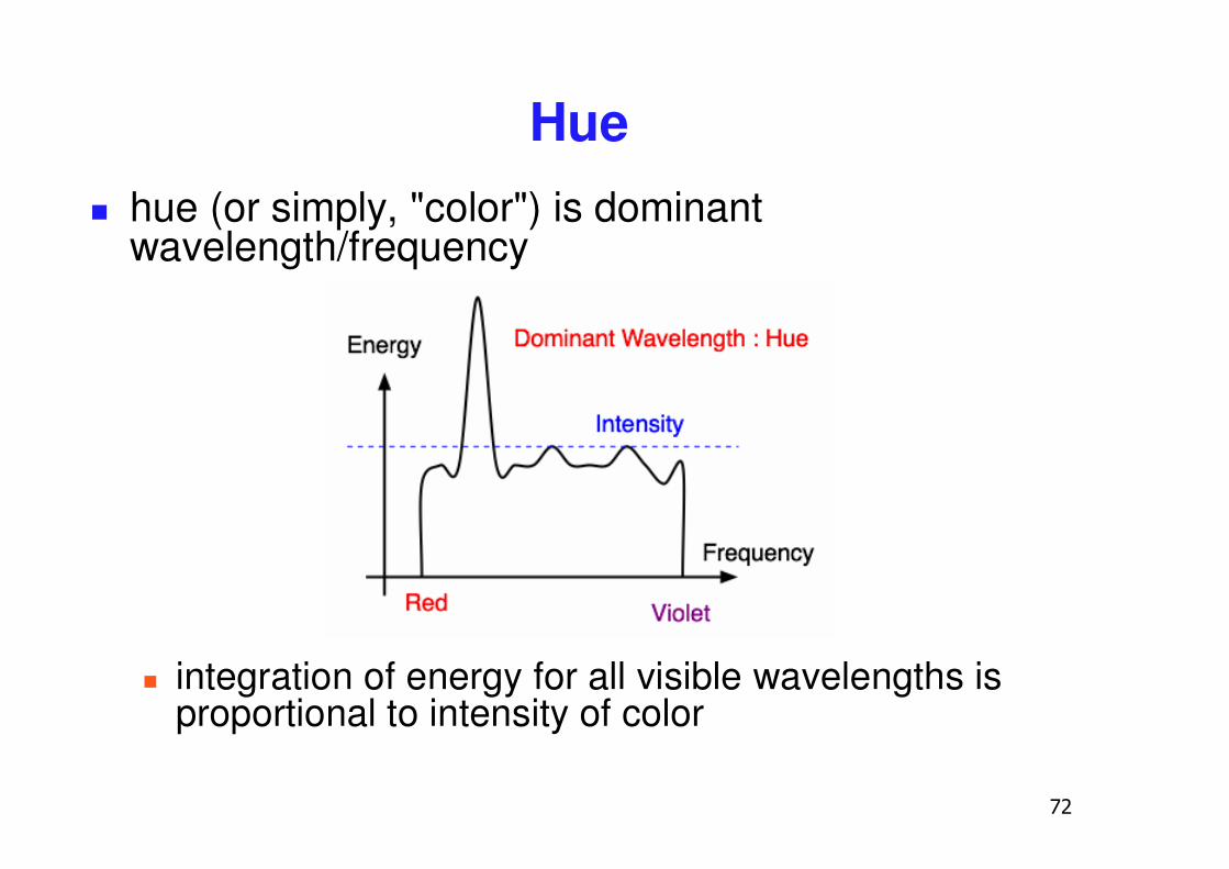
Hue� hue (or simply, "color") is dominant
wavelength/frequency
� integration of energy for all visible wavelengths is proportional to intensity of color
��
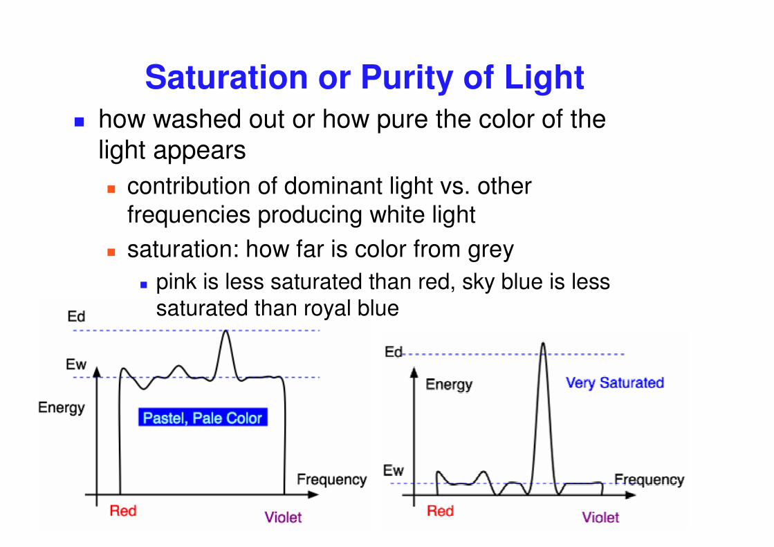
Saturation or Purity of Light � how washed out or how pure the color of the
light appears� contribution of dominant light vs. other
frequencies producing white light� saturation: how far is color from grey
� pink is less saturated than red, sky blue is less saturated than royal blue
��
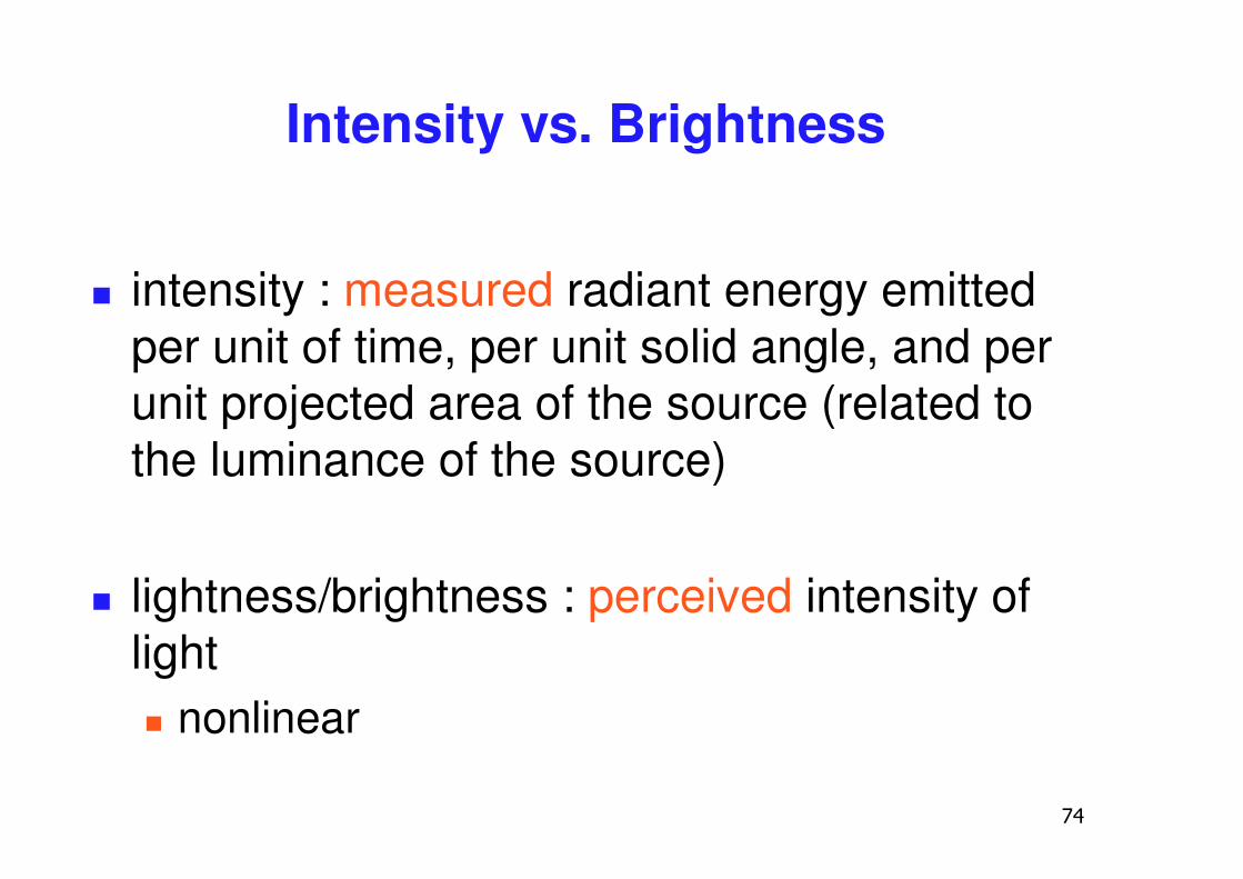
Intensity vs. Brightness
� intensity : measured radiant energy emitted per unit of time, per unit solid angle, and per unit projected area of the source (related to the luminance of the source)
� lightness/brightness : perceived intensity of light� nonlinear
��
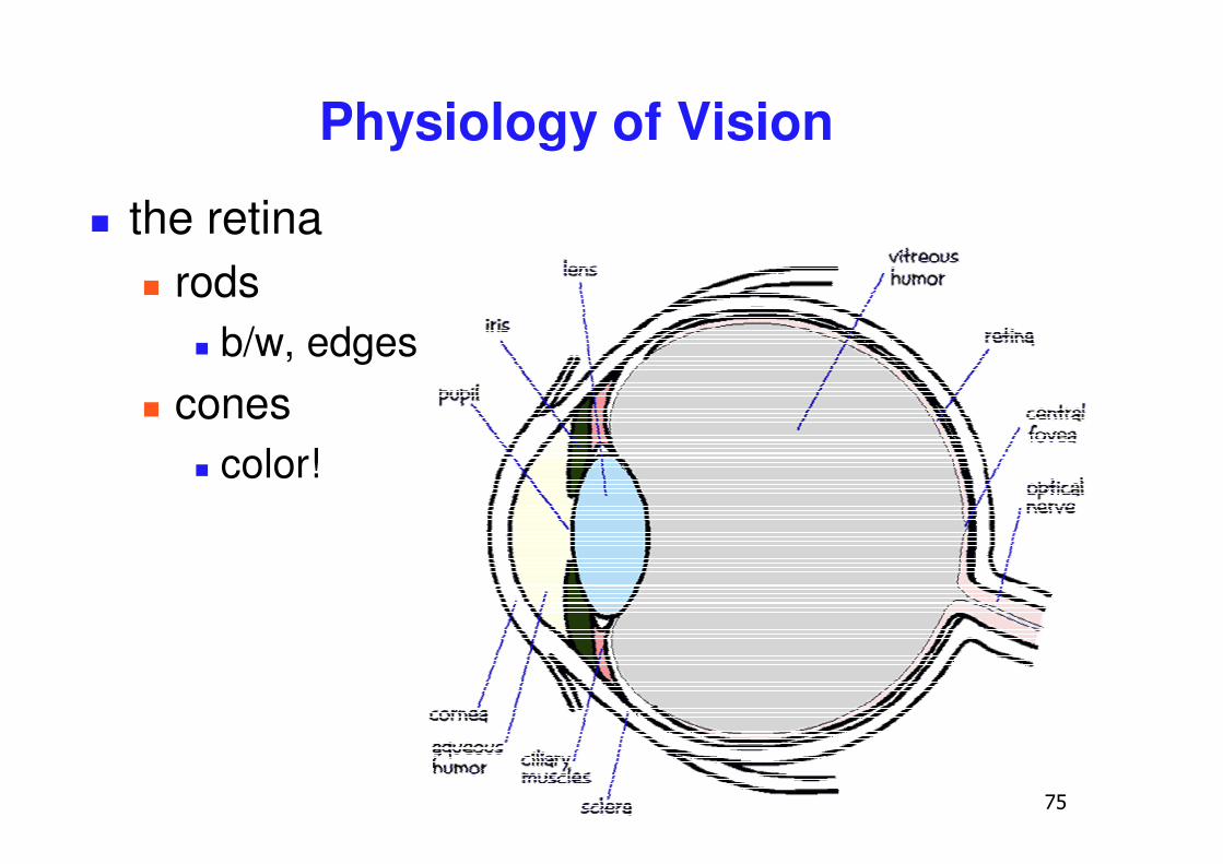
Physiology of Vision
� the retina� rods
� b/w, edges� cones
� color!
�
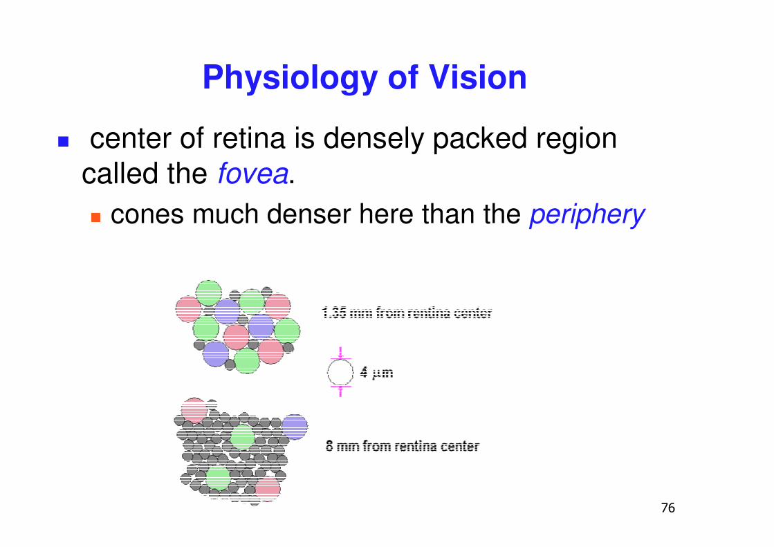
Physiology of Vision
� center of retina is densely packed region called the fovea. � cones much denser here than the periphery
��
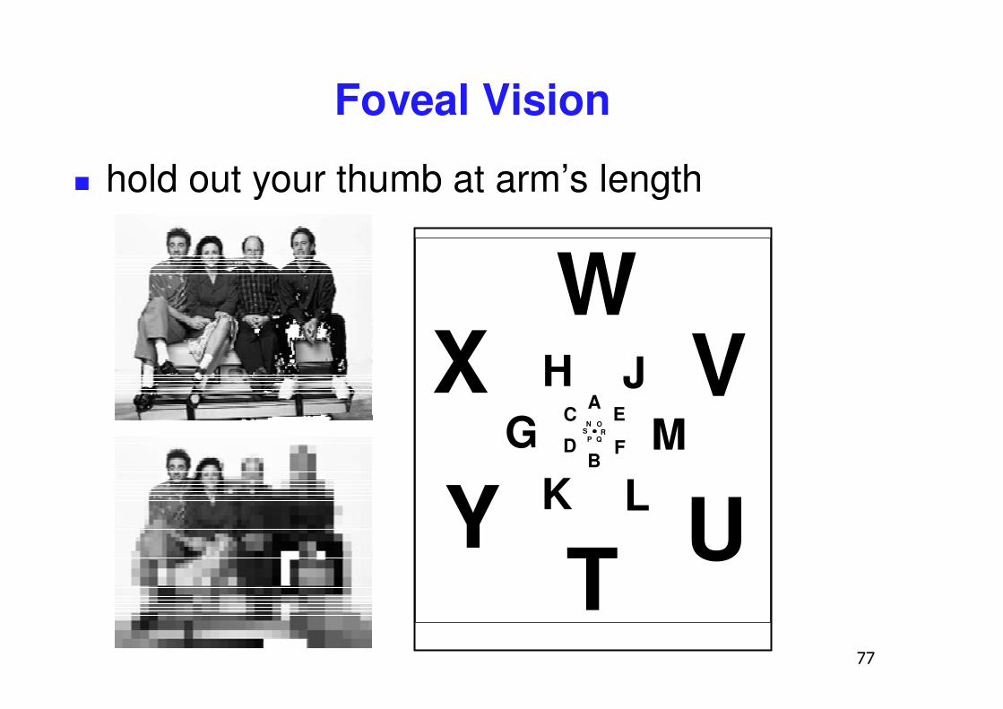
Foveal Vision
� hold out your thumb at arm’s length
A
B
C
D
E
FGH J
K LMN
P
O
QRS
T U
VW
X
Y
��
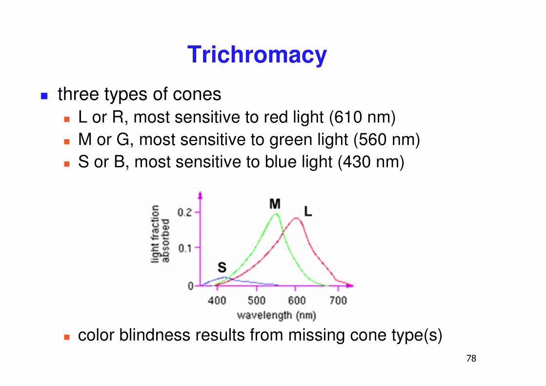
Trichromacy� three types of cones
� L or R, most sensitive to red light (610 nm) � M or G, most sensitive to green light (560 nm)� S or B, most sensitive to blue light (430 nm)
� color blindness results from missing cone type(s)
��
Metamers
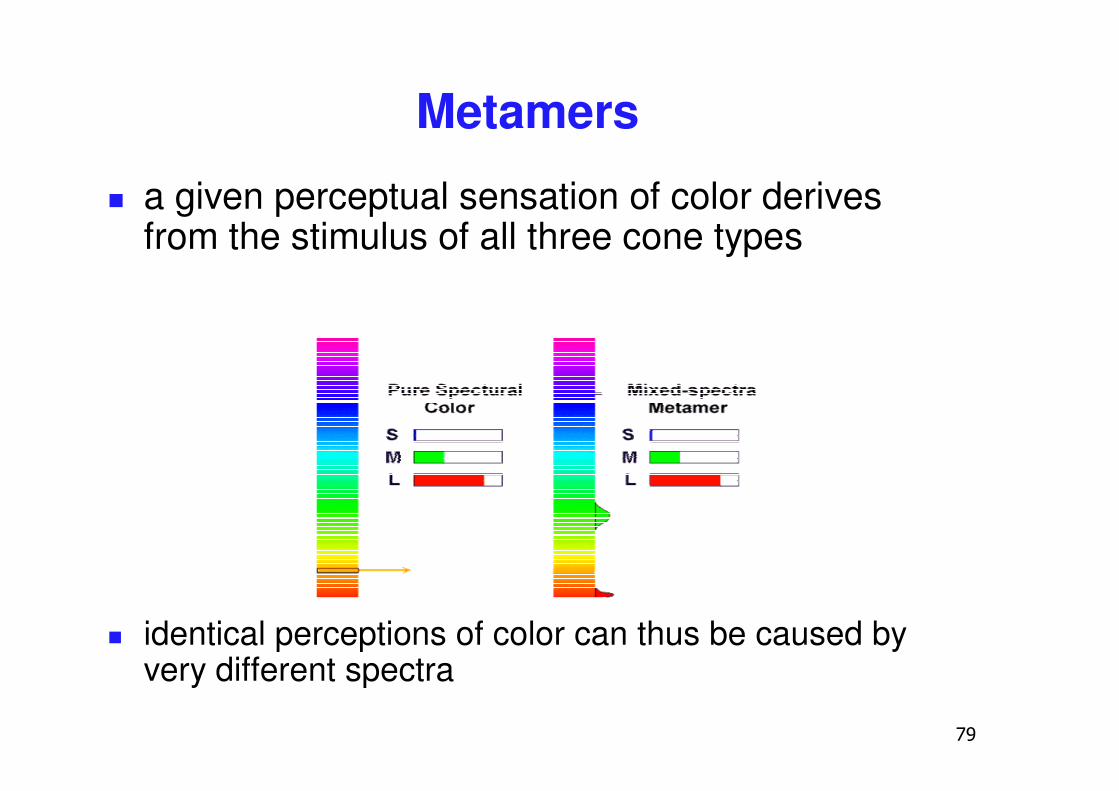
� a given perceptual sensation of color derives from the stimulus of all three cone types
� identical perceptions of color can thus be caused by very different spectra
�
Metamer Demo� http://www.cs.brown.edu/exploratories/freeSoftware/catalogs/color_theory.html
��
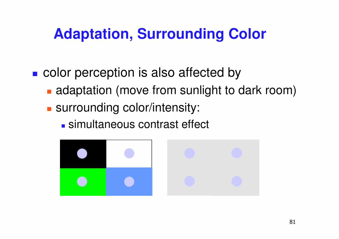
Adaptation, Surrounding Color
� color perception is also affected by� adaptation (move from sunlight to dark room)� surrounding color/intensity:
� simultaneous contrast effect
��
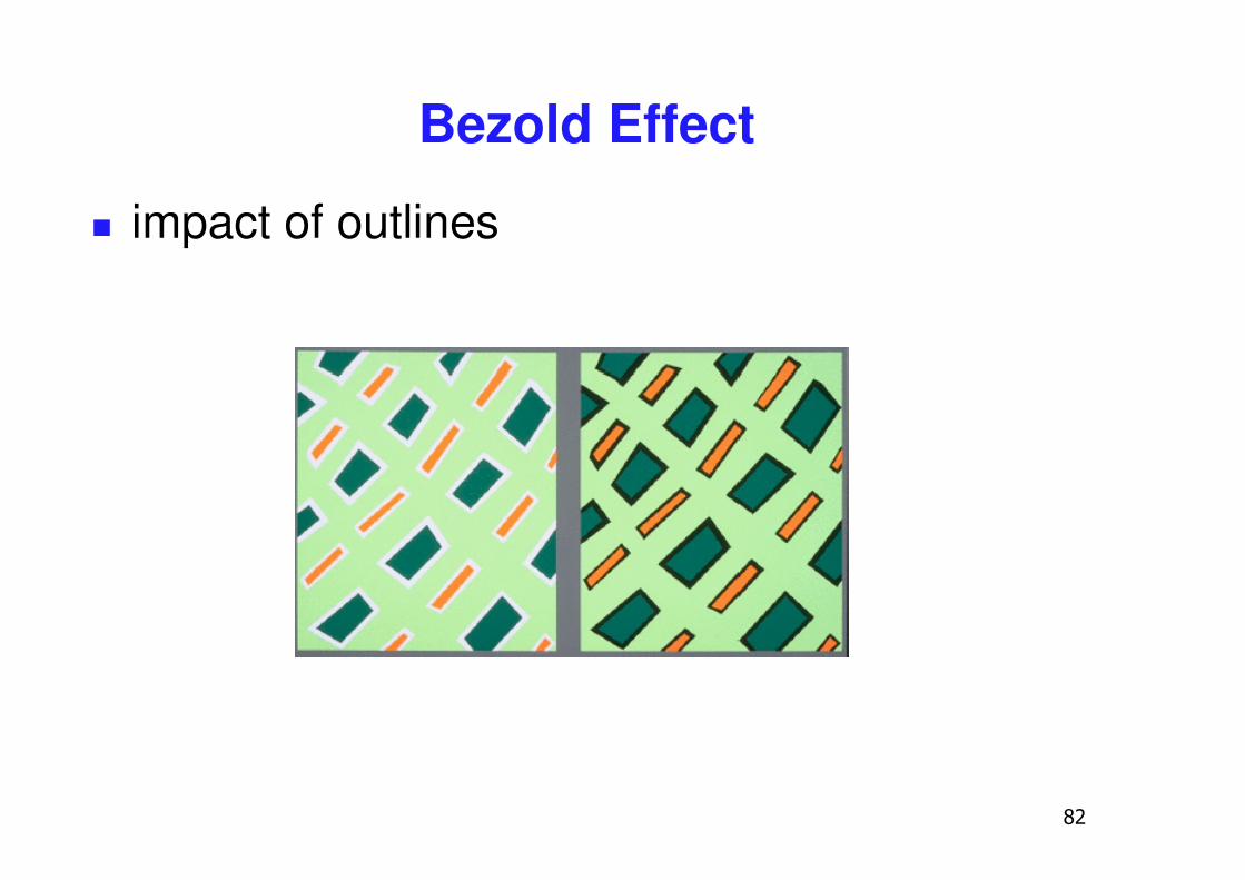
Bezold Effect
� impact of outlines
��
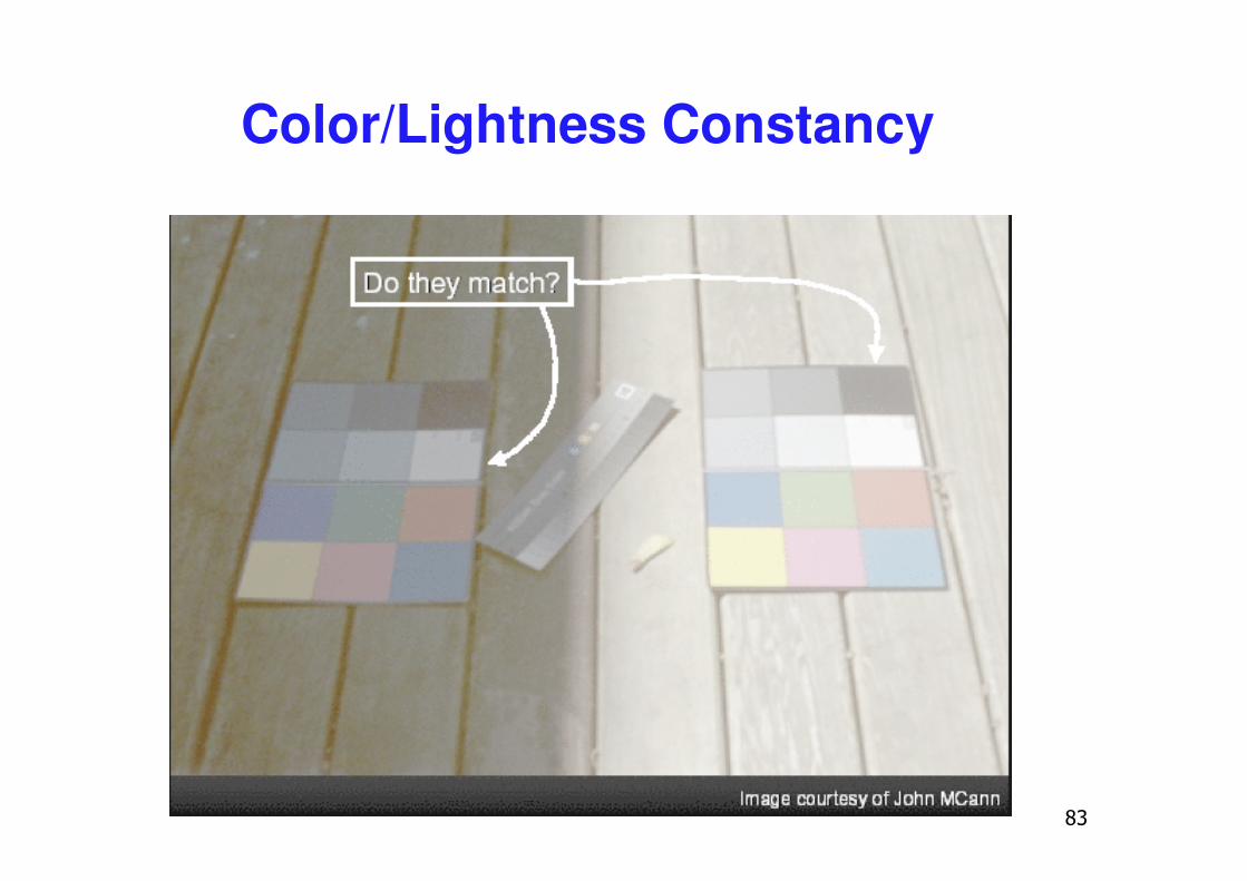
Color/Lightness Constancy
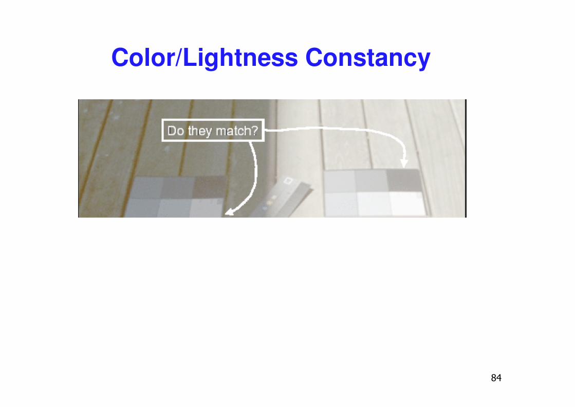
��
Color/Lightness Constancy
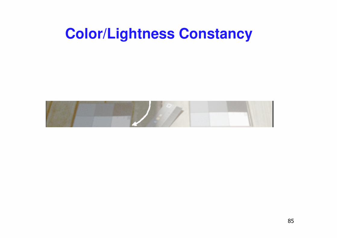
��
Color/Lightness Constancy
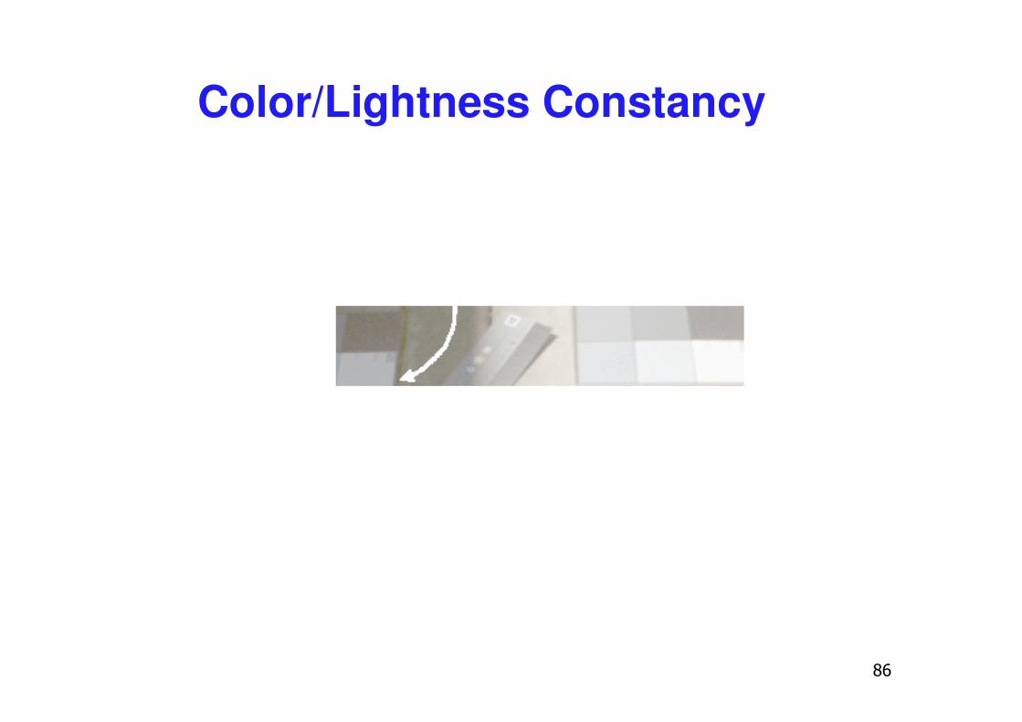
�
Color/Lightness Constancy
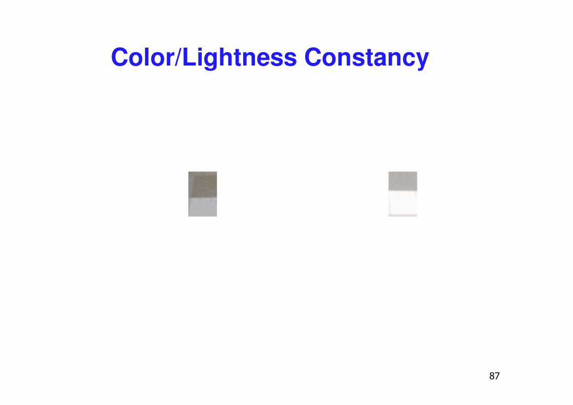
��
Color/Lightness Constancy
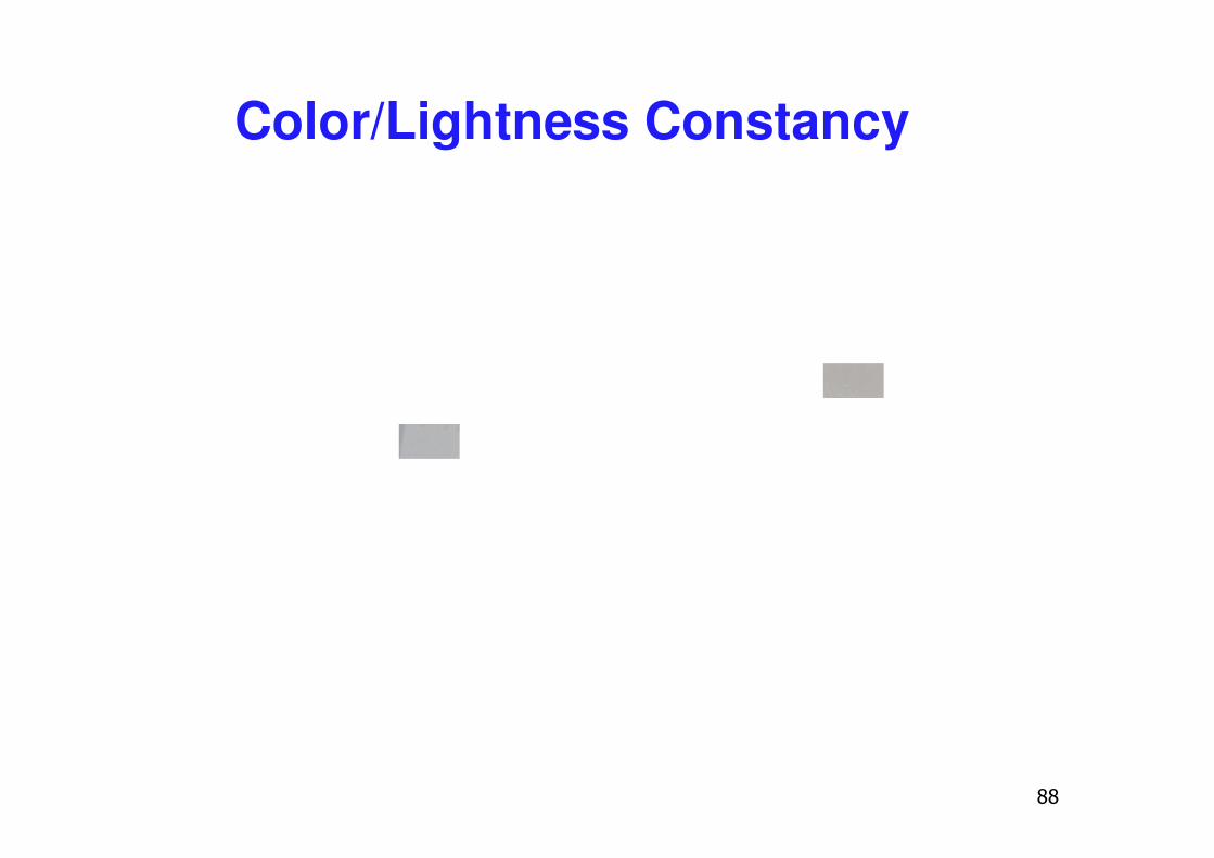
��
Color/Lightness Constancy
��
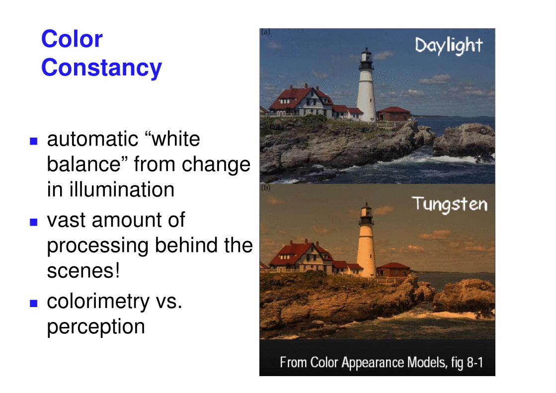
Color Constancy
� automatic “white balance” from change in illumination
� vast amount of processing behind the scenes!
� colorimetry vs. perception
�
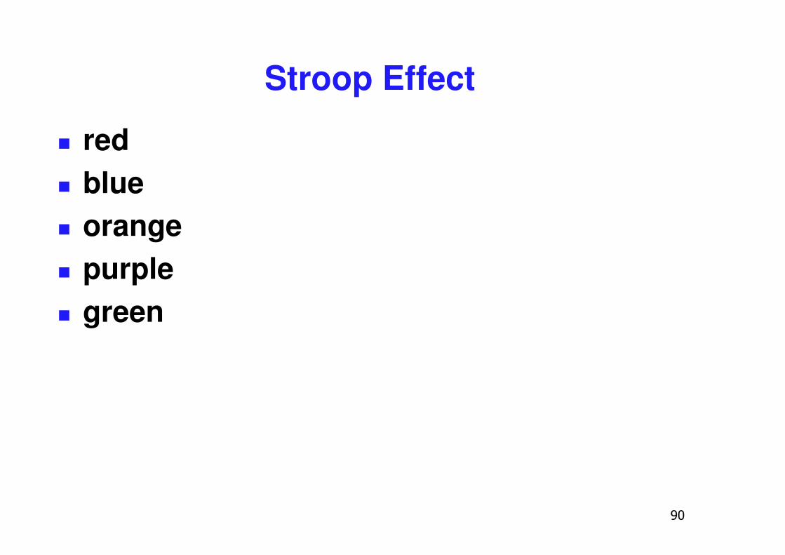
Stroop Effect
� red� blue� orange� purple� green
��
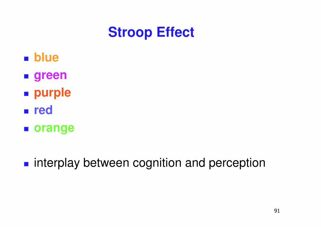
Stroop Effect
� blue� green� purple� red� orange
� interplay between cognition and perception
��
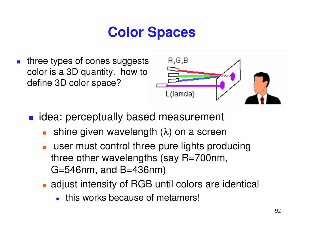
Color Spaces
� three types of cones suggests color is a 3D quantity. how to define 3D color space?
� idea: perceptually based measurement� shine given wavelength (λ) on a screen� user must control three pure lights producing
three other wavelengths (say R=700nm, G=546nm, and B=436nm)
� adjust intensity of RGB until colors are identical� this works because of metamers!
��
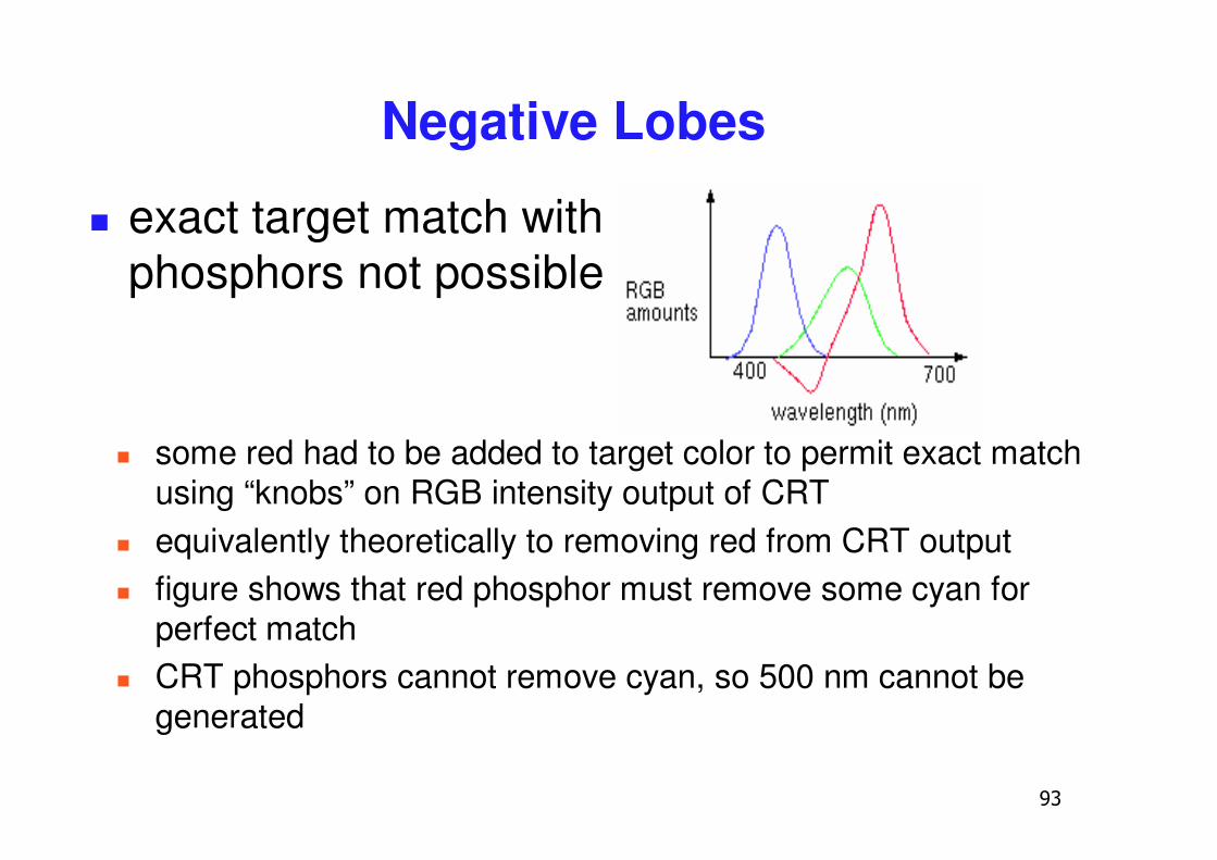
Negative Lobes
� exact target match with phosphors not possible
� some red had to be added to target color to permit exact match using “knobs” on RGB intensity output of CRT
� equivalently theoretically to removing red from CRT output� figure shows that red phosphor must remove some cyan for
perfect match� CRT phosphors cannot remove cyan, so 500 nm cannot be
generated
��
Negative Lobes
� can’t generate all other wavelenths with anyset of three positive monochromatic lights!
� solution: convert to new synthetic coordinate system to make the job easy
��
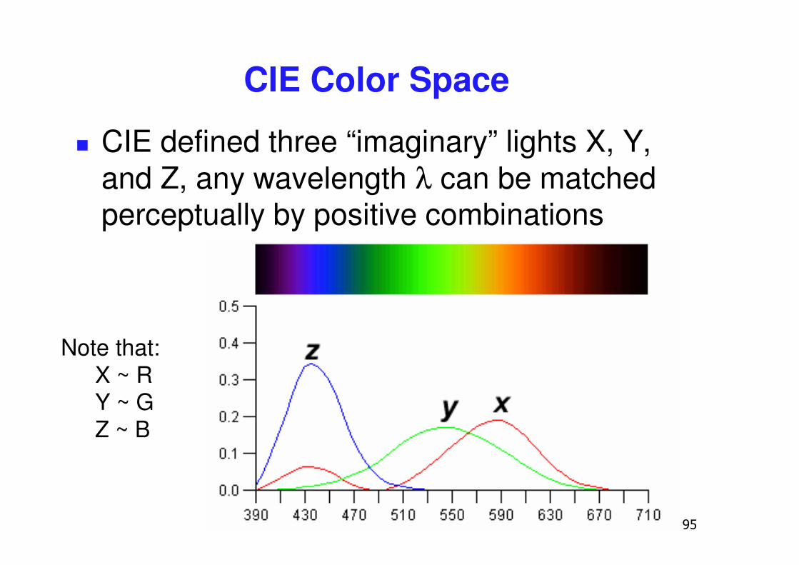
CIE Color Space
� CIE defined three “imaginary” lights X, Y, and Z, any wavelength λ can be matched perceptually by positive combinations
Note that:X ~ RY ~ GZ ~ B
�
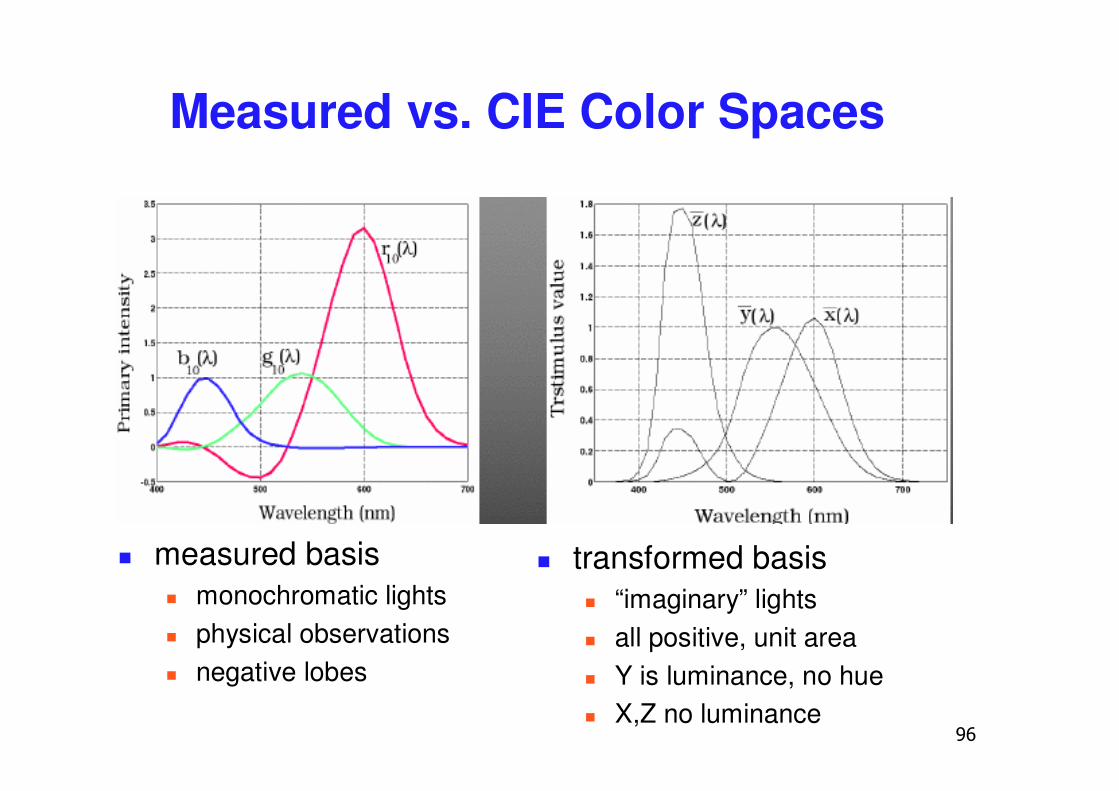
Measured vs. CIE Color Spaces
� measured basis� monochromatic lights� physical observations� negative lobes
� transformed basis� “imaginary” lights� all positive, unit area� Y is luminance, no hue� X,Z no luminance
��
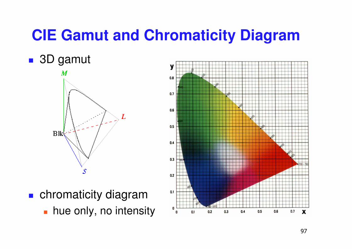
CIE Gamut and Chromaticity Diagram� 3D gamut
� chromaticity diagram� hue only, no intensity
��
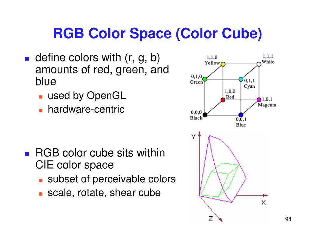
RGB Color Space (Color Cube)� define colors with (r, g, b)
amounts of red, green, and blue� used by OpenGL� hardware-centric
� RGB color cube sits within CIE color space� subset of perceivable colors� scale, rotate, shear cube
��
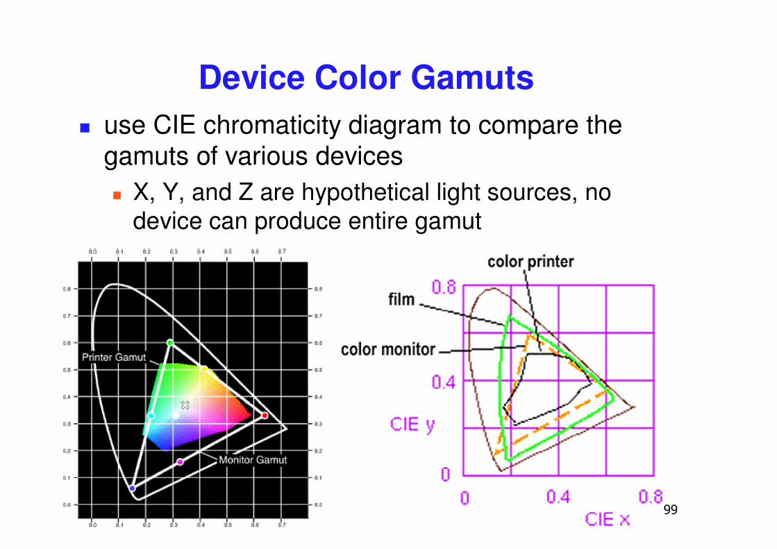
Device Color Gamuts� use CIE chromaticity diagram to compare the
gamuts of various devices� X, Y, and Z are hypothetical light sources, no
device can produce entire gamut
�
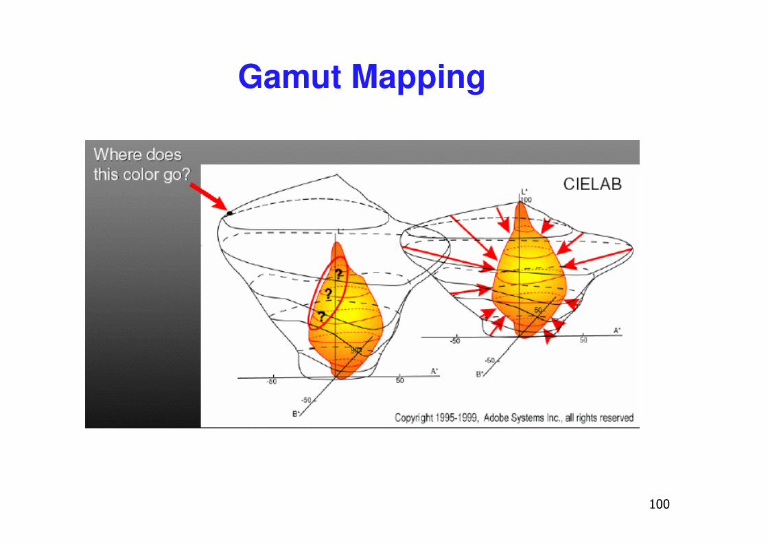
Gamut Mapping
��
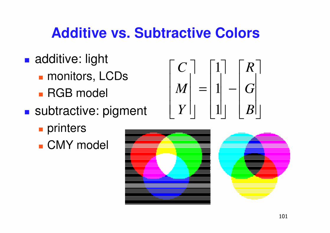
Additive vs. Subtractive Colors
� additive: light� monitors, LCDs� RGB model
� subtractive: pigment� printers� CMY model
���
�
�
���
�
�
−���
�
�
���
�
�
=���
�
�
���
�
�
B
G
R
Y
M
C
111
��
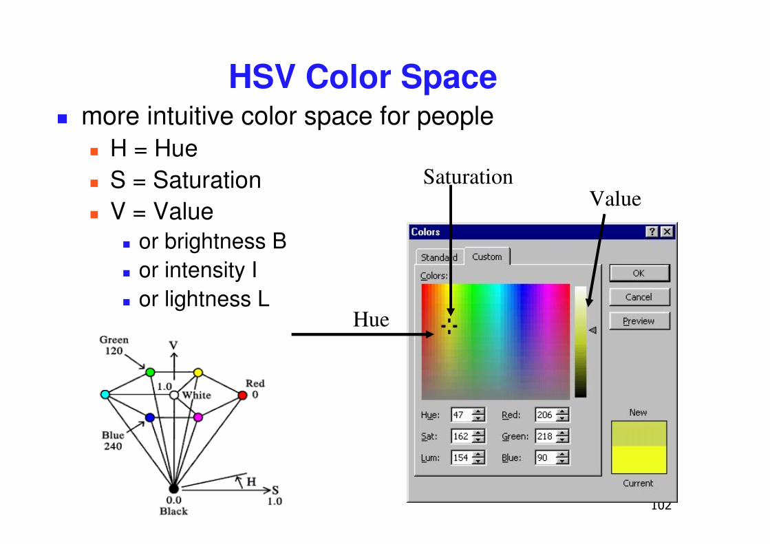
HSV Color Space� more intuitive color space for people
� H = Hue� S = Saturation� V = Value
� or brightness B� or intensity I� or lightness L
ValueSaturation
Hue
��
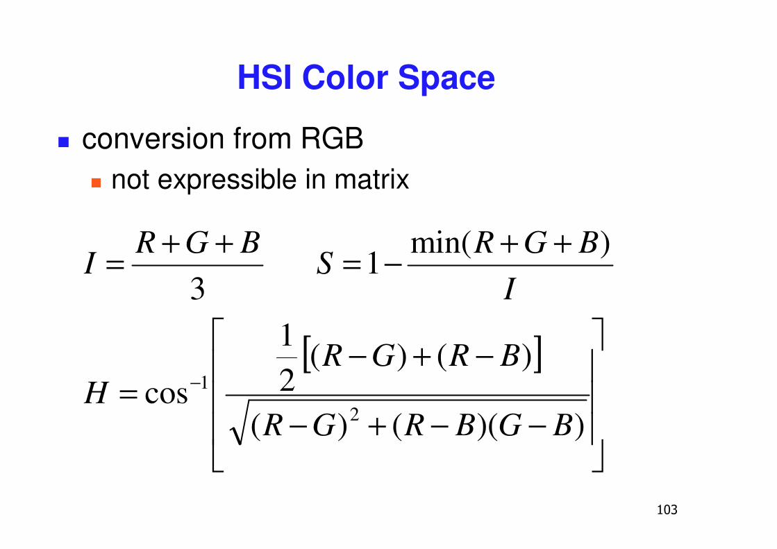
HSI Color Space
� conversion from RGB� not expressible in matrix
3BGR
I++=
IBGR
S)min(
1++−=
[ ]
���
�
�
���
�
�
−−+−
−+−= −
))(()(
)()(21
cos2
1
BGBRGR
BRGRH
��
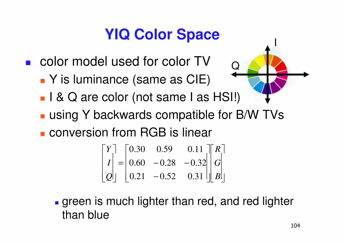
YIQ Color Space
� color model used for color TV� Y is luminance (same as CIE)� I & Q are color (not same I as HSI!)� using Y backwards compatible for B/W TVs� conversion from RGB is linear
� green is much lighter than red, and red lighter than blue
���
�
�
���
�
�
���
�
�
���
�
�
−−−=
���
�
�
���
�
�
B
G
R
Q
I
Y
31.052.021.032.028.060.0
11.059.030.0
Q
I
��
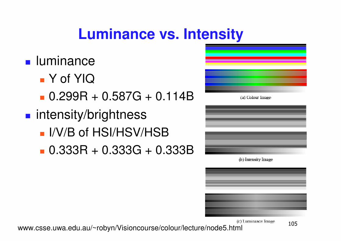
Luminance vs. Intensity
� luminance� Y of YIQ� 0.299R + 0.587G + 0.114B
� intensity/brightness � I/V/B of HSI/HSV/HSB� 0.333R + 0.333G + 0.333B
www.csse.uwa.edu.au/~robyn/Visioncourse/colour/lecture/node5.html
�
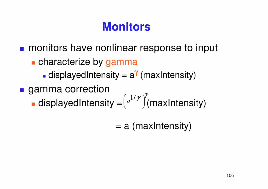
Monitors
� monitors have nonlinear response to input� characterize by gamma
� displayedIntensity = aγγγγ (maxIntensity)
� gamma correction� displayedIntensity = (maxIntensity)
= a (maxIntensity)
γγ��
�� /1a
��
Alpha
� transparency� (r,g,b,α)
� fraction we can see through� c = αcf + (1-α)cb
� compositing
��
Program 2: Terrain Navigation
� make colored terrain� 100x100 grid
� two triangles per grid cell� face color varies randomly
��
Navigating
� two flying modes: absolute and relative� absolute
� keyboard keys to increment/decrement� x/y/z position of eye, lookat, up vectors
� relative� mouse drags� incremental wrt current camera position� forward/backward motion� roll, pitch, and yaw angles
��
Hints: Viewing
� don’t forget to flip y coordinate from mouse� window system origin upper left� OpenGL origin lower left
� all viewing transformations belong in modelview matrix, not projection matrix� project 1 template incorrect with this!
���
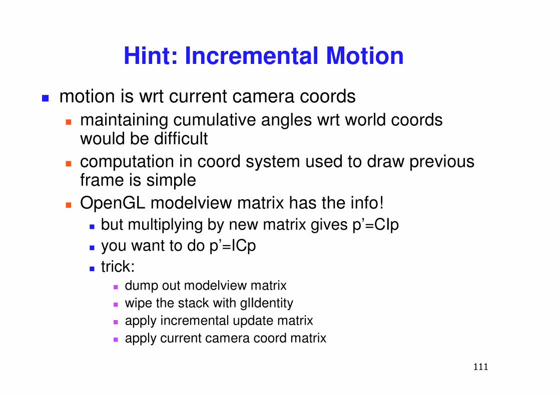
Hint: Incremental Motion� motion is wrt current camera coords
� maintaining cumulative angles wrt world coords would be difficult
� computation in coord system used to draw previous frame is simple
� OpenGL modelview matrix has the info!� but multiplying by new matrix gives p’=CIp� you want to do p’=ICp� trick:
� dump out modelview matrix� wipe the stack with glIdentity� apply incremental update matrix� apply current camera coord matrix

���
Demo