Embed Size (px)
Citation preview
University of Groningen
Rhombohedral Hf0.5Zr0.5O2 thin filmsWei, Yingfen
DOI:10.33612/diss.109882691
IMPORTANT NOTE: You are advised to consult the publisher's version (publisher's PDF) if you wish to cite fromit. Please check the document version below.
Document VersionPublisher's PDF, also known as Version of record
Publication date:2020
Link to publication in University of Groningen/UMCG research database
Citation for published version (APA):Wei, Y. (2020). Rhombohedral Hf0.5Zr0.5O2 thin films: Ferroelectricity and devices. RijksuniversiteitGroningen. https://doi.org/10.33612/diss.109882691
CopyrightOther than for strictly personal use, it is not permitted to download or to forward/distribute the text or part of it without the consent of theauthor(s) and/or copyright holder(s), unless the work is under an open content license (like Creative Commons).
The publication may also be distributed here under the terms of Article 25fa of the Dutch Copyright Act, indicated by the “Taverne” license.More information can be found on the University of Groningen website: https://www.rug.nl/library/open-access/self-archiving-pure/taverne-amendment.
Take-down policyIf you believe that this document breaches copyright please contact us providing details, and we will remove access to the work immediatelyand investigate your claim.
Downloaded from the University of Groningen/UMCG research database (Pure): http://www.rug.nl/research/portal. For technical reasons thenumber of authors shown on this cover page is limited to 10 maximum.
Download date: 18-02-2022
3
Chapter 3
A rhombohedral ferroelectric phase inepitaxially strained HZO thin films
Y. Wei, P. Nukala, M. Salverda, S. Matzen, H. Zhao, J. Momand, A. S. Everhardt,G. Agnus, G. R. Blake, P. Lecoeur, B. J. Kooi, J. Iniguez, B. Dkhil & B. Noheda,
Nature Materials 17, 1092 (2018).
Abstract
Hafnia-based thin films are a favoured candidate for the integration of robust ferroelectric-ity at the nanoscale into next-generation memory and logic devices. This is because theirferroelectric polarization becomes more robust as the size is reduced, exposing a type of fer-roelectricity whose mechanism still remains to be understood. Thin films with increasedcrystal quality are therefore needed. In this chapter, the epitaxial growth of Hf0.5Zr0.5O2
thin films on (001)-oriented La0.7Sr0.3MnO3/SrTiO3 substrates was reported. The films,which are under epitaxial compressive strain and predominantly (111)-oriented, displaylarge ferroelectric polarization values up to 34 µC/cm2 and do not need wake-up cycling.Structural characterization reveals a rhombohedral phase, different from the commonlyreported polar orthorhombic phase. This finding, in conjunction with density functionaltheory calculations, allows us to propose a compelling model for the formation of the fer-roelectric phase. In addition, these results point towards thin films of simple oxides as avastly unexplored class of nanoscale ferroelectrics.
3.1 IntroductionIn recent years, the ferroelectricity in doped HfO2 system has drew lots of interest from peopledue to its unexpected nanoscale ferroelectricity and great advantage of complementary metaloxide semiconductor (CMOS) compatibility which allows the wide application of non-volatileferroelectric memories.[1] However, most works about this new type of ferroelectrics reporton ALD-grown films, which are polycrystalline and contain multiple phases, including mon-oclinic (P21/c, m-phase), tetragonal (P42/nmc, t-phase), and orthorhombic (Pca21, o-phase).In addition, the similarity of these structures and the small size of crystallites make a com-plete structural characterization even more challenging. Therefore, well-oriented samples,preferably in a single phase, are desired to study the factors responsible for ferroelectricity.Single-crystal, epitaxial Y-doped HfO2 films have been achieved by PLD on yttrium oxide-stabilized zirconium oxide substrates with the polar o-phase[2], reaching a polarization of 16
3
52 3. A rhombohedral ferroelectric phase in epitaxially strained HZO thin films
µC/cm2. Here, we also utilize PLD to grow highly oriented ferroelectric Hf0.5Zr0.5O2 (HZO)films on a perovskite SrTiO3 (STO) substrate with La0.7Sr0.3MnO3 (LSMO) as a back electrodeto gain insights into the role of strain on the ferroelectricity in hafnia-based systems.
3.2 Experimental methods• Thin film synthesis: Thin films of HZO with thicknesses in the range of 1.5–27 nm weregrown by PLD on LSMO-buffered (001)-STO substrates. A KrF excimer laser with a wave-length of 248 nm was used to ablate polycrystalline targets of LSMO (purchased from PI-KEM,as the bottom electrode) and sequentially, HZO (home-made). LSMO was deposited using alaser fluence of 1 J/cm2 and a laser frequency of 1 Hz under a 0.15 mbar oxygen atmosphereand a substrate temperature of 775 ◦C. A ceramic HZO target (monoclinic P21/c phase) wassynthesized at 1400 ◦C by solid-state reaction, starting from HfO2 (99% purity) and ZrO2
(99.5% purity) powders. A fluence of 1.1 J/cm2 and repetition rate of 2 Hz was employed togrow the HZO films. The deposition was performed in an oxygen pressure of 0.1 mbar whilekeeping the substrates at a temperature of 800 ◦C. After deposition, the film was cooled downto room temperature at a rate of 5 ◦C/min under an oxygen pressure of 300 mbar.• X-ray structural characterization: The structure and orientation of the films was char-
acterized by XRD, using a Panalytical X’pert Pro diffractometer operating in two modes:using the line focus of the incident beam for high-resolution θ − 2θ specular scans, whichprovide the lattice parameters; and using the point focus of the incident beam, for high-intensity/medium-resolution measurements of pole figures, which involve scanning ϕ (az-imuthal angle) and χ (tilt of the sample plane around the incident beam direction) while thedetector is fixed at a particular Bragg reflection. Synchrotron diffraction measurements wereperformed at the P08 High Resolution Diffraction Beamline in PETRA III, with a wavelengthof λ = 1.378A, using a Kohzu six-circle diffractometer and a two-dimensional Pilatus 100kdetector.• Electron microscopy and EDS: (performed by Pavan Nukala and Jamo Momand) Cross-
sectional and plan-view specimens for electron microscopy were prepared via the standardprocedure of mechanical grinding and polishing the samples down to 100 µm, and dimpling(Gatan) followed by ion milling (PIPS II) to electron transparency. Some cross-sections werealso prepared via the focused ion beam (Helios 660 ThermoFischer Scientific) technique, andboth preparations yielded similar results. Electron microscopy and EDS were performed on aTitan G2, Cs-corrected TEM equipped with an extreme field-emission gun and a Super X EDSsystem with four solid-state detectors placed symmetrically along the optical axes. Atomic-resolution imaging was performed in the HAADF-STEM mode, where the intensity in theimage is ∼Z2, thus yielding a clear atomic number contrast. Images were analysed using Im-ageJ, TIA-ES Vision and Digital micrograph. EDS was performed simultaneously with imageacquisition in the HAADF-STEM mode. Chemical maps were acquired for 30 min with condi-tions optimized and collected at thousands of X-ray photons per second, and analysed usingBruker e-spirit software.• Electrical measurements: LSMO top electrodes were deposited by PLD with the same
growth condition as the bottom LSMO electrodes. LSMO top-electrode pads with different
3
3.3. Results and discussion 53
sizes were processed by physical etching (ion milling). Planar LSMO/HZO/LSMO capaci-tors were measured using a ferroelectric tester (AiXACCT, TF analyser 2000). The ferroelec-tric response of the films was tested via PUND[3] measurements, which are able to separateswitching currents from other contributions.
3.3 Results and discussion
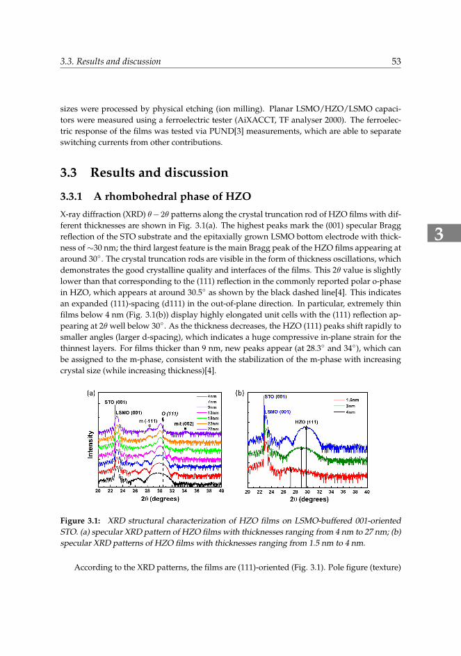
3.3.1 A rhombohedral phase of HZOX-ray diffraction (XRD) θ−2θ patterns along the crystal truncation rod of HZO films with dif-ferent thicknesses are shown in Fig. 3.1(a). The highest peaks mark the (001) specular Braggreflection of the STO substrate and the epitaxially grown LSMO bottom electrode with thick-ness of∼30 nm; the third largest feature is the main Bragg peak of the HZO films appearing ataround 30◦. The crystal truncation rods are visible in the form of thickness oscillations, whichdemonstrates the good crystalline quality and interfaces of the films. This 2θ value is slightlylower than that corresponding to the (111) reflection in the commonly reported polar o-phasein HZO, which appears at around 30.5◦ as shown by the black dashed line[4]. This indicatesan expanded (111)-spacing (d111) in the out-of-plane direction. In particular, extremely thinfilms below 4 nm (Fig. 3.1(b)) display highly elongated unit cells with the (111) reflection ap-pearing at 2θ well below 30◦. As the thickness decreases, the HZO (111) peaks shift rapidly tosmaller angles (larger d-spacing), which indicates a huge compressive in-plane strain for thethinnest layers. For films thicker than 9 nm, new peaks appear (at 28.3◦ and 34◦), which canbe assigned to the m-phase, consistent with the stabilization of the m-phase with increasingcrystal size (while increasing thickness)[4].
Figure 3.1: XRD structural characterization of HZO films on LSMO-buffered 001-orientedSTO. (a) specular XRD pattern of HZO films with thicknesses ranging from 4 nm to 27 nm; (b)specular XRD patterns of HZO films with thicknesses ranging from 1.5 nm to 4 nm.
According to the XRD patterns, the films are (111)-oriented (Fig. 3.1). Pole figure (texture)
3
54 3. A rhombohedral ferroelectric phase in epitaxially strained HZO thin films
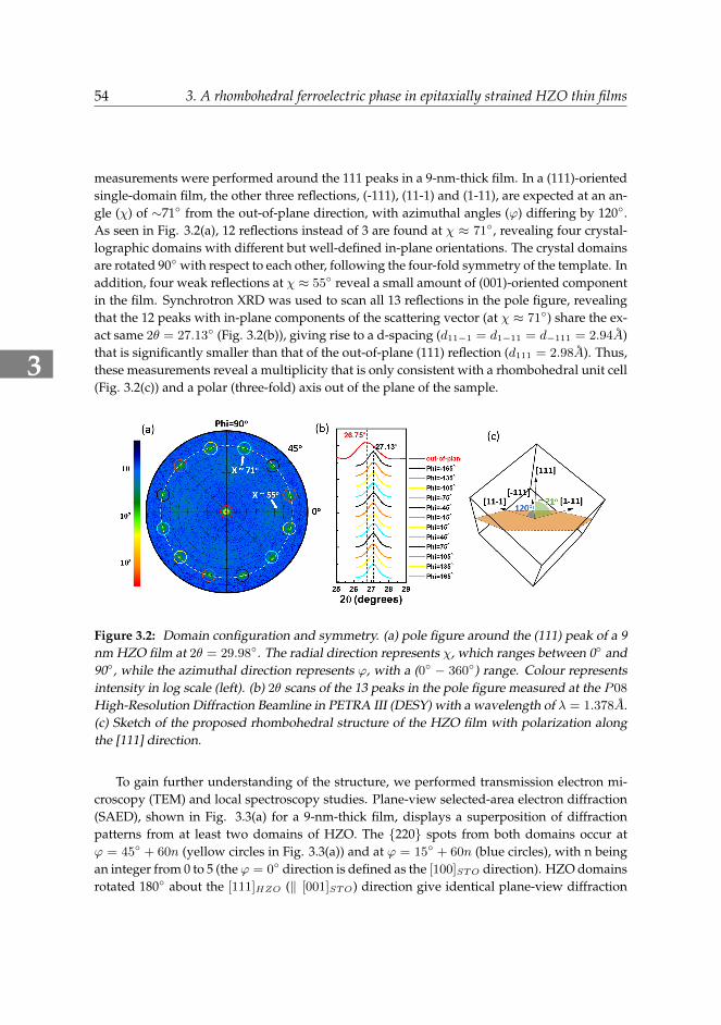
measurements were performed around the 111 peaks in a 9-nm-thick film. In a (111)-orientedsingle-domain film, the other three reflections, (-111), (11-1) and (1-11), are expected at an an-gle (χ) of ∼71◦ from the out-of-plane direction, with azimuthal angles (ϕ) differing by 120◦.As seen in Fig. 3.2(a), 12 reflections instead of 3 are found at χ ≈ 71◦, revealing four crystal-lographic domains with different but well-defined in-plane orientations. The crystal domainsare rotated 90◦ with respect to each other, following the four-fold symmetry of the template. Inaddition, four weak reflections at χ ≈ 55◦ reveal a small amount of (001)-oriented componentin the film. Synchrotron XRD was used to scan all 13 reflections in the pole figure, revealingthat the 12 peaks with in-plane components of the scattering vector (at χ ≈ 71◦) share the ex-act same 2θ = 27.13◦ (Fig. 3.2(b)), giving rise to a d-spacing (d11−1 = d1−11 = d−111 = 2.94A)that is significantly smaller than that of the out-of-plane (111) reflection (d111 = 2.98A). Thus,these measurements reveal a multiplicity that is only consistent with a rhombohedral unit cell(Fig. 3.2(c)) and a polar (three-fold) axis out of the plane of the sample.
Figure 3.2: Domain configuration and symmetry. (a) pole figure around the (111) peak of a 9nm HZO film at 2θ = 29.98◦. The radial direction represents χ, which ranges between 0◦ and90◦, while the azimuthal direction represents ϕ, with a (0◦ − 360◦) range. Colour representsintensity in log scale (left). (b) 2θ scans of the 13 peaks in the pole figure measured at the P08
High-Resolution Diffraction Beamline in PETRA III (DESY) with a wavelength of λ = 1.378A.(c) Sketch of the proposed rhombohedral structure of the HZO film with polarization alongthe [111] direction.
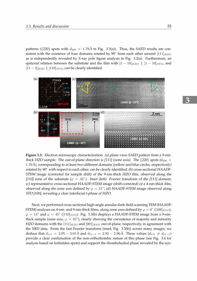
To gain further understanding of the structure, we performed transmission electron mi-croscopy (TEM) and local spectroscopy studies. Plane-view selected-area electron diffraction(SAED), shown in Fig. 3.3(a) for a 9-nm-thick film, displays a superposition of diffractionpatterns from at least two domains of HZO. The {220} spots from both domains occur atϕ = 45◦ + 60n (yellow circles in Fig. 3.3(a)) and at ϕ = 15◦ + 60n (blue circles), with n beingan integer from 0 to 5 (theϕ = 0◦ direction is defined as the [100]STO direction). HZO domainsrotated 180◦ about the [111]HZO (‖ [001]STO) direction give identical plane-view diffraction
3
3.3. Results and discussion 55
patterns ({220} spots with d220 = 1.79A in Fig. 3.3(a)). Thus, the SAED results are con-sistent with the existence of four domains rotated by 90◦ from each other around [111]HZOas is independently revealed by X-ray pole figure analysis in Fig. 3.2(a). Furthermore, anepitaxial relation between the substrate and the film with [1 − 10]HZO ‖ [1 − 10]STO , and[11− 2]HZO ‖ [110]STO , can be clearly identified.
Figure 3.3: Electron microscopy characterization. (a) plane-view SAED pattern from a 9-nm-thick HZO sample. The out-of-plane direction is [111] (zone axis). The {220} spots (d220 =
1.79A), corresponding to at least two different domains (yellow and blue circles, respectively)rotated by 90◦ with respect to each other, can be clearly identified; (b) cross-sectional HAADF-STEM image (corrected for sample drift) of the 9-nm-thick HZO film, observed along the[110] zone of the substrate (ϕ = 45◦). Inset (left): Fourier transform of the [111] domain;(c) representative cross-sectional HAADF-STEM image (drift-corrected) of a 4-nm-thick film,observed along the zone axis defined by ϕ = 15◦; (d) HAADF-STEM image observed alongSTO [100], revealing a clear interfacial t-phase of HZO.
Next, we performed cross-sectional high-angle annular dark-field scanning TEM (HAADF-STEM) analyses on 4-nm- and 9-nm-thick films, along zone axes defined by ϕ = 0◦ ([100]STO),ϕ = 15◦ and ϕ = 45◦ ([110]STO). Fig. 3.3(b) displays a HAADF-STEM image from a 9-nm-thick sample (zone axis, ϕ = 45◦), clearly showing the coexistence of majority and minorityHZO domains with the [111]HZO and [001]HZO out-of-plane, respectively, in agreement withthe XRD data. From the fast Fourier transform (inset, Fig. 3.3(b)) across many images, wededuce that d111 = 2.95 − 3.01A and d11−1 = 2.92 − 2.96A. These values (d111 6= d11−1)provide a clear confirmation of the non-orthorhombic nature of this phase (see Fig. 3.4 foranalysis based on forbidden spots) and support the rhombohedral phase revealed by the syn-
3
56 3. A rhombohedral ferroelectric phase in epitaxially strained HZO thin films
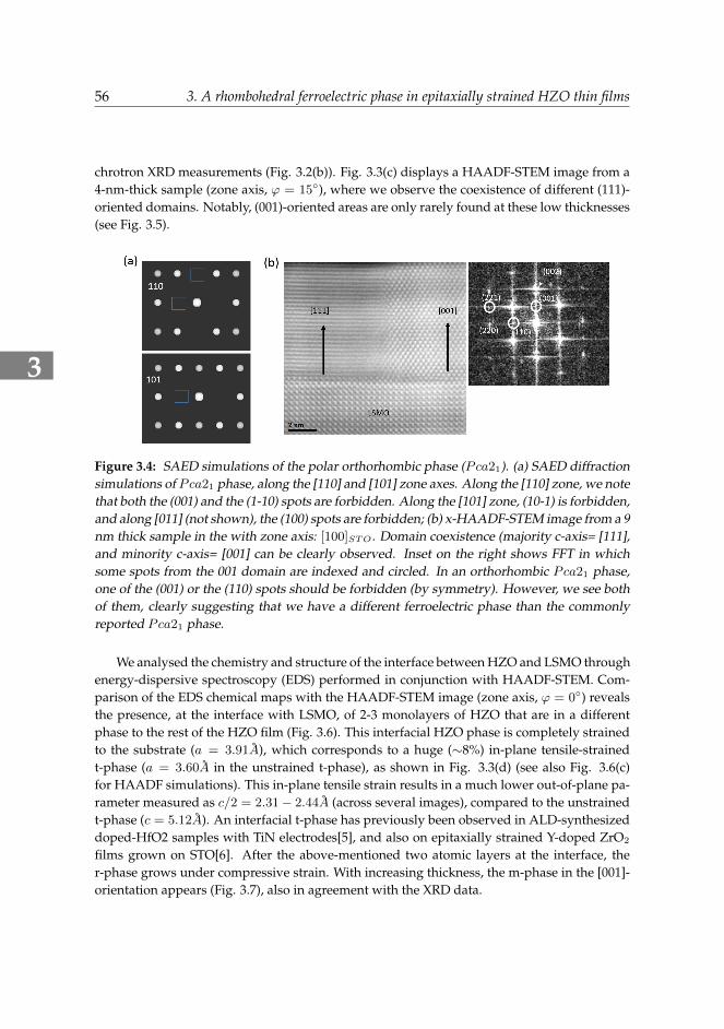
chrotron XRD measurements (Fig. 3.2(b)). Fig. 3.3(c) displays a HAADF-STEM image from a4-nm-thick sample (zone axis, ϕ = 15◦), where we observe the coexistence of different (111)-oriented domains. Notably, (001)-oriented areas are only rarely found at these low thicknesses(see Fig. 3.5).
Figure 3.4: SAED simulations of the polar orthorhombic phase (Pca21). (a) SAED diffractionsimulations of Pca21 phase, along the [110] and [101] zone axes. Along the [110] zone, we notethat both the (001) and the (1-10) spots are forbidden. Along the [101] zone, (10-1) is forbidden,and along [011] (not shown), the (100) spots are forbidden; (b) x-HAADF-STEM image from a 9nm thick sample in the with zone axis: [100]STO . Domain coexistence (majority c-axis= [111],and minority c-axis= [001] can be clearly observed. Inset on the right shows FFT in whichsome spots from the 001 domain are indexed and circled. In an orthorhombic Pca21 phase,one of the (001) or the (110) spots should be forbidden (by symmetry). However, we see bothof them, clearly suggesting that we have a different ferroelectric phase than the commonlyreported Pca21 phase.
We analysed the chemistry and structure of the interface between HZO and LSMO throughenergy-dispersive spectroscopy (EDS) performed in conjunction with HAADF-STEM. Com-parison of the EDS chemical maps with the HAADF-STEM image (zone axis, ϕ = 0◦) revealsthe presence, at the interface with LSMO, of 2-3 monolayers of HZO that are in a differentphase to the rest of the HZO film (Fig. 3.6). This interfacial HZO phase is completely strainedto the substrate (a = 3.91A), which corresponds to a huge (∼8%) in-plane tensile-strainedt-phase (a = 3.60A in the unstrained t-phase), as shown in Fig. 3.3(d) (see also Fig. 3.6(c)for HAADF simulations). This in-plane tensile strain results in a much lower out-of-plane pa-rameter measured as c/2 = 2.31− 2.44A (across several images), compared to the unstrainedt-phase (c = 5.12A). An interfacial t-phase has previously been observed in ALD-synthesizeddoped-HfO2 samples with TiN electrodes[5], and also on epitaxially strained Y-doped ZrO2
films grown on STO[6]. After the above-mentioned two atomic layers at the interface, ther-phase grows under compressive strain. With increasing thickness, the m-phase in the [001]-orientation appears (Fig. 3.7), also in agreement with the XRD data.
3
3.3. Results and discussion 57
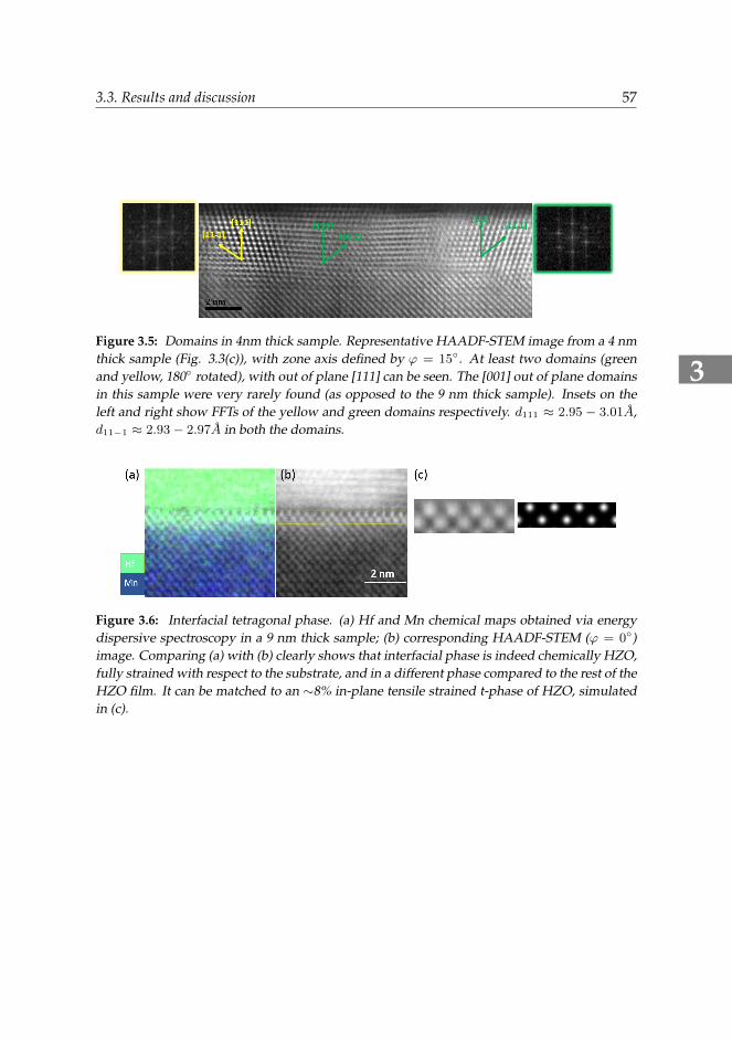
Figure 3.5: Domains in 4nm thick sample. Representative HAADF-STEM image from a 4 nmthick sample (Fig. 3.3(c)), with zone axis defined by ϕ = 15◦. At least two domains (greenand yellow, 180◦ rotated), with out of plane [111] can be seen. The [001] out of plane domainsin this sample were very rarely found (as opposed to the 9 nm thick sample). Insets on theleft and right show FFTs of the yellow and green domains respectively. d111 ≈ 2.95 − 3.01A,d11−1 ≈ 2.93− 2.97A in both the domains.
Figure 3.6: Interfacial tetragonal phase. (a) Hf and Mn chemical maps obtained via energydispersive spectroscopy in a 9 nm thick sample; (b) corresponding HAADF-STEM (ϕ = 0◦)image. Comparing (a) with (b) clearly shows that interfacial phase is indeed chemically HZO,fully strained with respect to the substrate, and in a different phase compared to the rest of theHZO film. It can be matched to an ∼8% in-plane tensile strained t-phase of HZO, simulatedin (c).
3
58 3. A rhombohedral ferroelectric phase in epitaxially strained HZO thin films
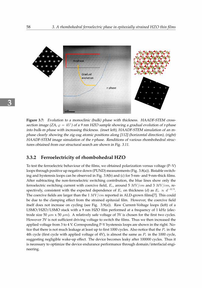
Figure 3.7: Evolution to a monoclinic (bulk) phase with thickness. HAADF-STEM cross-section image (ZA, ϕ = 45◦) of a 9 nm HZO sample showing a gradual evolution of r-phaseinto bulk-m phase with increasing thickness. (inset left), HAADF-STEM simulation of an m-phase clearly showing the zig-zag atomic positions along [112] (horizontal direction), (right)HAADF-STEM image simulation of the r-phase. Renditions of various rhombohedral struc-tures obtained from our structural search are shown in Fig. 3.11.
3.3.2 Ferroelectricity of rhombohedral HZO
To test the ferroelectric behaviour of the films, we obtained polarization versus voltage (P–V)loops through positive up negative down (PUND) measurements (Fig. 3.8(a)). Bistable switch-ing and hysteresis loops can be observed in Fig. 3.8(b) and (c) for 5-nm- and 9-nm-thick films.After subtracting the non-ferroelectric switching contribution, the blue lines show only theferroelectric switching current with coercive field, Ec, around 5 MV/cm and 3 MV/cm, re-spectively, consistent with the expected dependence of Ec on thickness (d) as Ec ∝ d−2/3.The coercive fields are larger than the 1 MV/cm reported in ALD-grown films[7]. This couldbe due to the clamping effect from the strained epitaxial film. However, the coercive fielditself does not increase on cycling (see Fig. 3.9(a)). Raw Current-Voltage loops (left) of aLSMO/HZO/LSMO stack with a 9 nm HZO film performed at a frequency of 1 kHz (elec-trode size 50 µm x 50 µm). A relatively safe voltage of 3V is chosen for the first two cycles.However 3V is not sufficient driving voltage to switch the films. Thus we then increased theapplied voltage from 3 to 4 V. Corresponding P-V hysteresis loops are shown in the right. No-tice that there is not much leakage at least up to first 1000 cycles. Also notice that the Pr in the4th cycle (first cycle with applied voltage of 4V), is almost the same as Pr in the 1000 cycle,suggesting negligible wake-up effect. The device becomes leaky after 100000 cycles. Thus itis necessary to optimize the device endurance performance through domain/interfacial engi-neering.
3
3.3. Results and discussion 59
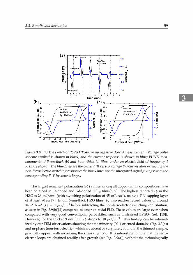
Figure 3.8: (a) The sketch of PUND (Positive up negative down) measurement. Voltage pulsescheme applied is shown in black, and the current response is shown in blue; PUND mea-surements of 5-nm-thick (b) and 9-nm-thick (c) films under an electric field of frequency 1kHz are shown. The blue lines are the current (I) versus voltage (V) curves after extracting thenon-ferroelectric switching response; the black lines are the integrated signal giving rise to thecorresponding P–V hysteresis loops.
The largest remanent polarization (Pr) values among all doped-hafnia compositions havebeen obtained in La-doped and Gd-doped HfO2 films[8, 9]. The highest reported Pr in theHZO is 26 µC/cm2 (with switching polarization of 45 µC/cm2), using a TiN capping layerof at least 90 nm[7]. In our 5-nm-thick HZO films, Pr also reaches record values of around34 µC/cm2 (Pr = 50µC/cm2 before subtracting the non-ferroelectric switching contribution,as seen in Fig. 3.9(b))[2] compared to other epitaxial PLD. These values are large even whencompared with very good conventional perovskites, such as unstrained BaTiO3 (ref. [10]).However, for the thicker 9 nm film, Pr drops to 18 µC/cm2. This finding can be rational-ized by our TEM observations showing that the minority (001)-oriented domains (Fig. 3.3(b))and m-phase (non-ferroelectric), which are absent or very rarely found in the thinnest sample,gradually appear with increasing thickness (Fig. 3.7). It is interesting to note that the ferro-electric loops are obtained readily after growth (see Fig. 3.9(a)), without the technologically
3
60 3. A rhombohedral ferroelectric phase in epitaxially strained HZO thin films
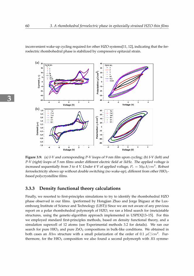
inconvenient wake-up cycling required for other HZO systems[11, 12], indicating that the fer-roelectric rhombohedral phase is stabilized by compressive epitaxial strain.
Figure 3.9: (a) I-V and corresponding P-V loops of 9 nm film upon cycling; (b) I-V (left) andP-V (right) loops of 5 nm films under different electric field at 1kHz. The applied voltage isincreased sequentially from 3 to 4 V. Under 4 V of applied voltage, Pr = 50µA/cm2. Robustferroelectricity shows up without double switching (no wake-up), different from other HfO2-based polycrystalline films.
3.3.3 Density functional theory calculations
Finally, we resorted to first-principles simulations to try to identify the rhombohedral HZOphase observed in our films. (performed by Hongjian Zhao and Jorge Iniguez at the Lux-embourg Institute of Science and Technology (LIST)) Since we are not aware of any previousreport on a polar rhombohedral polymorph of HZO, we ran a blind search for (meta)stablestructures, using the genetic-algorithm approach implemented in USPEX[13–15]. For thiswe employed standard first-principles methods, based on density functional theory, and asimulation supercell of 12 atoms (see Experimental methods 3.2 for details). We ran oursearch for pure HfO2 and pure ZrO2 compositions in bulk-like conditions. We obtained inboth cases an R3m structure with a small polarization of the order of 0.1 µC/cm2. Fur-thermore, for the HfO2 composition we also found a second polymorph with R3 symme-
3
3.3. Results and discussion 61
try and a polarization of 41 µC/cm2. These rhombohedral phases lie above the P21/c bulkground state that is usually discussed in the literature on HfO2, which explains why theyhave not been previously reported or observed. More precisely, from our calculations we ob-tain E(R3m) − E(P21/c) = 158meV f.u.−1 and E(R3) − E(P21/c) = 195meV f.u.−1 forHfO2. Note that the polar Pca21 phase of hafnia discussed in the literature is also more stablethan these rhombohedral polymorphs, as we obtain E(Pca21) − E(P21/c) = 64meV f.u.−1
(in agreement with ref.[16], which reports 62 meV f.u.−1 for this energy gap).
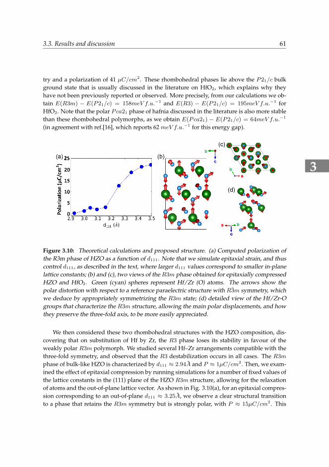
Figure 3.10: Theoretical calculations and proposed structure. (a) Computed polarization ofthe R3m phase of HZO as a function of d111. Note that we simulate epitaxial strain, and thuscontrol d111, as described in the text, where larger d111 values correspond to smaller in-planelattice constants; (b) and (c), two views of the R3m phase obtained for epitaxially compressedHZO and HfO2. Green (cyan) spheres represent Hf/Zr (O) atoms. The arrows show thepolar distortion with respect to a reference paraelectric structure with R3m symmetry, whichwe deduce by appropriately symmetrizing the R3m state; (d) detailed view of the Hf/Zr-Ogroups that characterize the R3m structure, allowing the main polar displacements, and howthey preserve the three-fold axis, to be more easily appreciated.
We then considered these two rhombohedral structures with the HZO composition, dis-covering that on substitution of Hf by Zr, the R3 phase loses its stability in favour of theweakly polar R3m polymorph. We studied several Hf–Zr arrangements compatible with thethree-fold symmetry, and observed that the R3 destabilization occurs in all cases. The R3m
phase of bulk-like HZO is characterized by d111 ≈ 2.94A and P ≈ 1µC/cm2. Then, we exam-ined the effect of epitaxial compression by running simulations for a number of fixed values ofthe lattice constants in the (111) plane of the HZO R3m structure, allowing for the relaxationof atoms and the out-of-plane lattice vector. As shown in Fig. 3.10(a), for an epitaxial compres-sion corresponding to an out-of-plane d111 ≈ 3.25A, we observe a clear structural transitionto a phase that retains the R3m symmetry but is strongly polar, with P ≈ 15µC/cm2. This
3
62 3. A rhombohedral ferroelectric phase in epitaxially strained HZO thin films
d111 value is within the range of what we observe in our thinnest HZO films (for our filmswith thickness between 1.5 nm and 9 nm, we estimate d111 values ranging between ∼ 3.27A
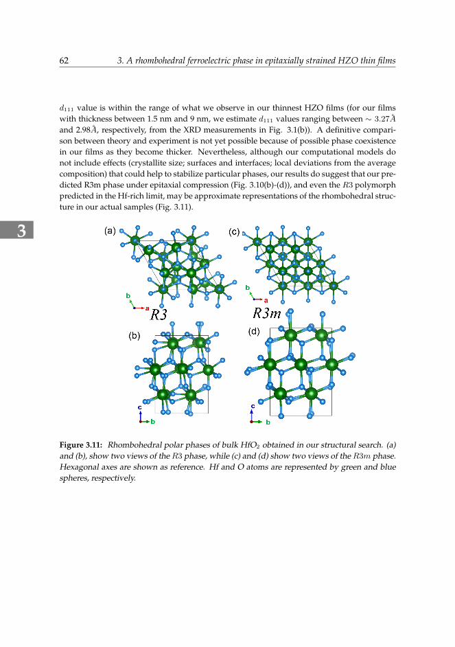
and 2.98A, respectively, from the XRD measurements in Fig. 3.1(b)). A definitive compari-son between theory and experiment is not yet possible because of possible phase coexistencein our films as they become thicker. Nevertheless, although our computational models donot include effects (crystallite size; surfaces and interfaces; local deviations from the averagecomposition) that could help to stabilize particular phases, our results do suggest that our pre-dicted R3m phase under epitaxial compression (Fig. 3.10(b)-(d)), and even the R3 polymorphpredicted in the Hf-rich limit, may be approximate representations of the rhombohedral struc-ture in our actual samples (Fig. 3.11).
Figure 3.11: Rhombohedral polar phases of bulk HfO2 obtained in our structural search. (a)and (b), show two views of theR3 phase, while (c) and (d) show two views of theR3m phase.Hexagonal axes are shown as reference. Hf and O atoms are represented by green and bluespheres, respectively.
3
3.4. Conclusion 63
3.4 Conclusion
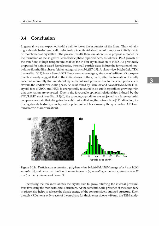
In general, we can expect epitaxial strain to lower the symmetry of the films. Thus, obtain-ing a rhombohedral unit cell under isotropic epitaxial strain would imply an initially cubicor rhombohedral crystallite. The present results therefore allow us to propose a model forthe formation of the as-grown ferroelectric phase reported here, as follows. PLD growth ofthe thin films at high temperature enables the in situ crystallization of HZO. As previouslyproposed for hafnia-based ferroelectrics, the small particle sizes induce the formation of low-volume fluorite-like phases (either tetragonal or cubic)[17–19]. A plane-view bright-field TEMimage (Fig. 3.12) from a 9 nm HZO film shows an average grain size of ∼10 nm. Our exper-iments strongly suggest that in the initial stages of the growth, after the formation of a fullycoherent, atomically thin interfacial layer, the internal pressure due to the small particle sizefavours the undistorted cubic phase. As established by Demkov and Navrotsky[20], the (111)crystal face of ZrO2 and HfO2 is energetically favourable, so cubic crystallites growing withthat orientation are expected. Due to the favourable epitaxial relationships induced by theSTO/LSMO stack (see Fig. 3.3(a)), the growing crystallites are subjected to a large epitaxialcompressive strain that elongates the cubic unit cell along the out-of-plane [111] direction, in-ducing rhombohedral symmetry with a polar unit cell (as shown by the synchrotron XRD andferroelectric characterization).
Figure 3.12: Particle size estimation. (a) plane view bright-field TEM image of a 9 nm HZOsample; (b) grain size distribution from the image in (a) revealing a median grain size of ∼10nm (median grain area of 84 nm2).
Increasing the thickness allows the crystal size to grow, relieving the internal pressure,thus favouring the monoclinic bulk structure. At the same time, the presence of the secondarym-phase also helps to release the elastic energy of the compressively strained structure. Eventhough XRD shows only traces of the m-phase for thicknesses above ∼10 nm, the TEM analy-
3
64 3. A rhombohedral ferroelectric phase in epitaxially strained HZO thin films
sis shows that monoclinic (001)-oriented crystallites are already present in the 9-nm-thick film(Fig. 3.7).
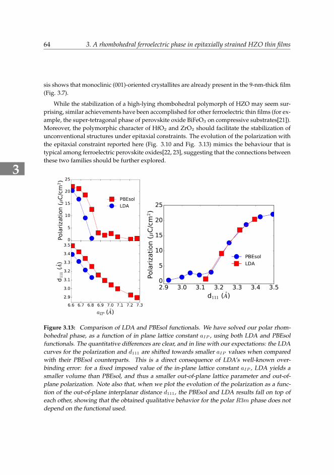
While the stabilization of a high-lying rhombohedral polymorph of HZO may seem sur-prising, similar achievements have been accomplished for other ferroelectric thin films (for ex-ample, the super-tetragonal phase of perovskite oxide BiFeO3 on compressive substrates[21]).Moreover, the polymorphic character of HfO2 and ZrO2 should facilitate the stabilization ofunconventional structures under epitaxial constraints. The evolution of the polarization withthe epitaxial constraint reported here (Fig. 3.10 and Fig. 3.13) mimics the behaviour that istypical among ferroelectric perovskite oxides[22, 23], suggesting that the connections betweenthese two families should be further explored.
Figure 3.13: Comparison of LDA and PBEsol functionals. We have solved our polar rhom-bohedral phase, as a function of in plane lattice constant aIP , using both LDA and PBEsolfunctionals. The quantitative differences are clear, and in line with our expectations: the LDAcurves for the polarization and d111 are shifted towards smaller aIP values when comparedwith their PBEsol counterparts. This is a direct consequence of LDA’s well-known over-binding error: for a fixed imposed value of the in-plane lattice constant aIP , LDA yields asmaller volume than PBEsol, and thus a smaller out-of-plane lattice parameter and out-of-plane polarization. Note also that, when we plot the evolution of the polarization as a func-tion of the out-of-plane interplanar distance d111, the PBEsol and LDA results fall on top ofeach other, showing that the obtained qualitative behavior for the polar R3m phase does notdepend on the functional used.
3
3.5. Outlook 65
In this work, we show that strain engineering can be used in very thin films of HZO toinduce a ferroelectric rhombohedral phase, with a large Pr of 34 µC/cm2. Further work isrequired to tackle issues associated with the strain requisite, such as larger coercive fields ormore complex integration in three-dimensional architectures. The insights gained in this workprovide the missing clues in the understanding of robust ferroelectricity in thin hafnia-basedsystems, and also help to overcome one of the main issues for their device utilization: thewake-up cycling. Our theoretical calculations predict an even larger polarization for the rhom-bohedral phases of Hf-rich compositions, and comparable values for epitaxially compressedHZO structures. In addition, this work suggests a pathway to generate large ferroelectricpolarization in nanocrystallites of simple oxides, whose rich phase diagrams include cubic,tetragonal and rhombohedral phases, and in particular in materials with a clear preferencefor one specific crystal orientation. These highly oriented cubic phases can be stabilized dur-ing growth and deformed into a polar structure via epitaxial strain. Furthermore, the highlyepitaxial growth of ultrathin ferroelectric hafnia-based films on LSMO has great potential formultiferroic tunnel junctions.
3.5 OutlookOur results of single crystal hafnia-based ferroelectrics grown on a perovsite magnetic oxidehave already inspired others. The group from ICMAB-CSIC, was able to directly reproducesimilar behavior in our work showing the reproducibility and robustness of this behaviour,which adds to the excellent behavour of this material, already recognized as highly advanta-geous for ferroelectric applications.[24] However, the following fundamental aspects of thisnew-type of ferroelectricity still remain unclear, for example, what causes the robustnessagainst depolarization effects; why are the coercive fields large (∼2 MV/cm); is the polariza-tion switching mechanism domain-mediated like in conventional ferroelectrics or somethingdifferent, and is there a temperature dependent ferroelectric-paraelectric transition and if sowhat is the high-symmetry paraelectric phase? All of these questions need to be addressedfor better understanding its ferroelectricity in the future.
3
66 3. A rhombohedral ferroelectric phase in epitaxially strained HZO thin films
Bibliography[1] J. Muller, T. Boscke, S. Muller, E. Yurchuk, P. Polakowski, J. Paul, D. Martin, T. Schenk,
K. Khullar, A. Kersch, et al., “Ferroelectric hafnium oxide: A cmos-compatible and highlyscalable approach to future ferroelectric memories,” in 2013 IEEE International ElectronDevices Meeting, pp. 10–8, IEEE, 2013.
[2] T. Shimizu, K. Katayama, T. Kiguchi, A. Akama, T. J. Konno, O. Sakata, and H. Funakubo,“The demonstration of significant ferroelectricity in epitaxial y-doped hfo2 film,” Scien-tific Reports 6, p. 32931, 2016.
[3] K. Rabe, C. H. Ahn, and J.-M. Triscone, Physics of Ferroelectrics: A Modern Perspective,Springer, 2007.
[4] M. Hyuk Park, H. Joon Kim, Y. Jin Kim, W. Lee, T. Moon, and C. Seong Hwang, “Evo-lution of phases and ferroelectric properties of thin hf0.5zr0.5o2 films according to thethickness and annealing temperature,” Applied Physics Letters 102(24), p. 242905, 2013.
[5] M. Pesic, F. P. G. Fengler, L. Larcher, A. Padovani, T. Schenk, E. D. Grimley, X. Sang, J. M.LeBeau, S. Slesazeck, U. Schroeder, et al., “Physical mechanisms behind the field-cyclingbehavior of hfo2-based ferroelectric capacitors,” Advanced Functional Materials 26(25),pp. 4601–4612, 2016.
[6] J. Garcia-Barriocanal, A. Rivera-Calzada, M. Varela, Z. Sefrioui, E. Iborra, C. Leon, S. J.Pennycook, and J. Santamaria, “Colossal ionic conductivity at interfaces of epitaxial zro2:
y2o3/srtio3 heterostructures,” Science 321(5889), pp. 676–680, 2008.
[7] S. J. Kim, D. Narayan, J.-G. Lee, J. Mohan, J. S. Lee, J. Lee, H. S. Kim, Y.-C. Byun, A. T.Lucero, C. D. Young, et al., “Large ferroelectric polarization of tin/hf0.5zr0.5o2/tin ca-pacitors due to stress-induced crystallization at low thermal budget,” Applied Physics Let-ters 111(24), p. 242901, 2017.
[8] J. Muller, T. Boscke, S. Muller, E. Yurchuk, P. Polakowski, J. Paul, D. Martin, T. Schenk,K. Khullar, A. Kersch, et al., “Ferroelectric hafnium oxide: a cmos-compatible and highlyscalable approach to future ferroelectric memories,” in 2013 IEEE International ElectronDevices Meeting, pp. 10–8, IEEE, 2013.
[9] M. Hoffmann, U. Schroeder, T. Schenk, T. Shimizu, H. Funakubo, O. Sakata, D. Pohl,M. Drescher, C. Adelmann, R. Materlik, et al., “Stabilizing the ferroelectric phase in dopedhafnium oxide,” Journal of Applied Physics 118(7), p. 072006, 2015.
[10] H. N. Lee, H. M. Christen, M. F. Chisholm, C. M. Rouleau, and D. H. Lowndes, “Strongpolarization enhancement in asymmetric three-component ferroelectric superlattices,”Nature 433(7024), p. 395, 2005.
[11] H. J. Kim, M. H. Park, Y. J. Kim, Y. H. Lee, T. Moon, K. Do Kim, S. D. Hyun, andC. S. Hwang, “A study on the wake-up effect of ferroelectric hf0.5zr0.5o2 films by pulse-switching measurement,” Nanoscale 8(3), pp. 1383–1389, 2016.
3
Bibliography 67
[12] T. Schenk, U. Schroeder, M. Pesic, M. Popovici, Y. V. Pershin, and T. Mikolajick, “Elec-tric field cycling behavior of ferroelectric hafnium oxide,” ACS Applied Materials & Inter-faces 6(22), pp. 19744–19751, 2014.
[13] A. O. Lyakhov, A. R. Oganov, H. T. Stokes, and Q. Zhu, “New developments in evolu-tionary structure prediction algorithm uspex,” Computer Physics Communications 184(4),pp. 1172–1182, 2013.
[14] A. R. Oganov and C. W. Glass, “Crystal structure prediction using ab initio evolution-ary techniques: principles and applications,” The Journal of Chemical Physics 124(24),p. 244704, 2006.
[15] C. W. Glass, A. R. Oganov, and N. Hansen, “Uspex-evolutionary crystal structure predic-tion,” Computer Physics Communications 175(11-12), pp. 713–720, 2006.
[16] R. Materlik, C. Kunneth, and A. Kersch, “The origin of ferroelectricity in hf1-xzrxo2: a computational investigation and a surface energy model,” Journal of AppliedPhysics 117(13), p. 134109, 2015.
[17] C.-H. Lu, J. M. Raitano, S. Khalid, L. Zhang, and S.-W. Chan, “Cubic phase stabilization innanoparticles of hafnia-zirconia oxides: Particle-size and annealing environment effects,”Journal of Applied Physics 103(12), p. 124303, 2008.
[18] P. Shen and W. Lee, “(111)-specific coalescence twinning and martensitic transformationof tetragonal zro2 condensates,” Nano Letters 1(12), pp. 707–711, 2001.
[19] D. Vollath, F. Fischer, M. Hagelstein, and D. Szabo, “Phases and phase transformationsin nanocrystalline zro2,” Journal of Nanoparticle Research 8(6), pp. 1003–1016, 2006.
[20] A. A. Demkov and A. Navrotsky, Materials fundamentals of gate dielectrics, vol. 256,Springer, 2005.
[21] H. Bea, B. Dupe, S. Fusil, R. Mattana, E. Jacquet, B. Warot-Fonrose, F. Wilhelm, A. Ro-galev, S. Petit, V. Cros, et al., “Evidence for room-temperature multiferroicity in a com-pound with a giant axial ratio,” Physical Review Letters 102(21), p. 217603, 2009.
[22] S. Tinte, K. M. Rabe, and D. Vanderbilt, “Anomalous enhancement of tetragonality inpbtio3 induced by negative pressure,” Physical Review B 68(14), p. 144105, 2003.
[23] J. C. Wojdeł and J. Iniguez, “Ab initio indications for giant magnetoelectric effects drivenby structural softness,” Physical Review Letters 105(3), p. 037208, 2010.
[24] J. Lyu, I. Fina, R. Solanas, J. Fontcuberta, and F. Sanchez, “Robust ferroelectricity in epi-taxial hf1/2zr1/2o2 thin films,” Applied Physics Letters 113(8), p. 082902, 2018.