Embed Size (px)
Citation preview
University of Minnesota Nano Fabrication Center
Standard Operating Procedure
Page 1 of 7
Equipment Name: Graphene CVD Furnace Badger Name: graphene-1 Revision Number: 7
Model: Revisionist: T. Whipple
Location: Area 1 Keller Date: 7/17/2017
1 Description
The Graphene CVD Furnace system is a vacuum furnace which deposits a thin film
layer. This is done by cycling certain gasses for amount of time. This builds a
graphene film on the substrate. It is manually controlled machine and is NOT easy to
run, so pay close attention while running it.
2 Safety
a The system uses several gases, such as Hydrogen and Methane and these gases
will burn if exposed to air, or could explode.
b The system uses electrical power and is under vacuum and is hot, so be aware
these items. There should be no odor whatsoever. If you smell an odor, put
system in a safe condition, and leave the area and Contact staff
c As the system is being heated the chamber are very hot so be careful while
loading and unloading wafers, do not burn your sleeve.
3 Restrictions/Requirements
a Must be a qualified user on the system and only during Mon – Fri 7 AM – 6PM.
4 Required Facilities
a Supplied gasses, Nitrogen, Hydrogen, Argon, Methane
c House Exhaust
5 Definitions
a Buttons that you will press will be displayed in SOP as color BLUE as [ off]
b N A
6 Operating Instructions
a LOGGING ON
1 Check Badger for other reservations for the system first.
2 Enable " graphene-1 " on Badger: in Keller / Chemical Vapor Deposition.
b SETUP PROCEDURE
1. Make sure samples are ready then check LEL Sensor Operation is spinning.
University of Minnesota Nano Fabrication Center
Standard Operating Procedure
Page 2 of 7
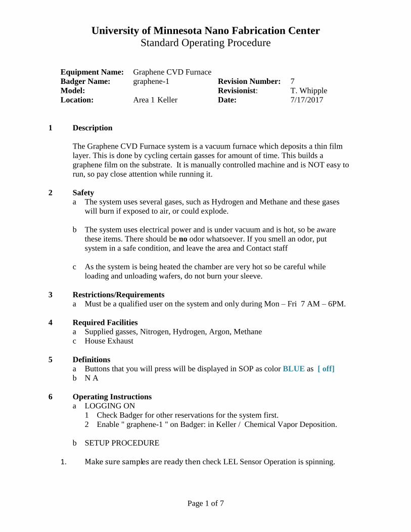
2. Turn on 647 flow controller by pressing any key on 647, then press [esc] [2] for
Extended display. [on] then [esc] [2]
Next press [on] [ 0/All ] this will turn Flow ON. Make sure 647 read “FLOW
ON” & “GAS ON” bottom line on the display, GAS ON will be ON after steps 4-8.
3. Turn on 651 pressure control ( ON switch is in reach from below, back toward power
cord). Make sure valve is closed (the green LED left of the “CLOSE” button is on)
Display screen of the 647 flow controller.
LEL sensor
Argon valve
647 interface
Flow on
University of Minnesota Nano Fabrication Center
Standard Operating Procedure
Page 3 of 7
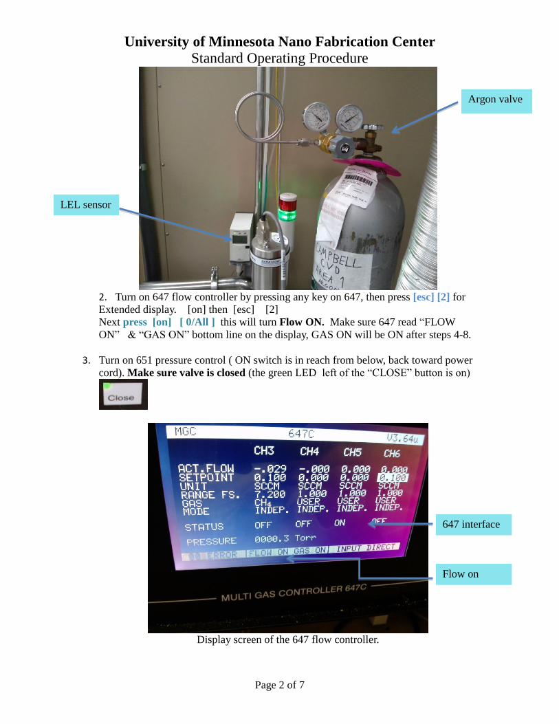
Fig3. 647 flow controller left and close up of the 651 pressure controller right image.
4. Open Argon cylinder & regulator valves
5. Open water flow valve and verify flow (should be around 0.7 gpm)
6. Open nitrogen valve (expect no flow to show at this time).
Notice this image is with both values in the ON position.
647 flow controller 651 pressure control
Water valve Nitrogen valve
University of Minnesota Nano Fabrication Center
Standard Operating Procedure
Page 4 of 7
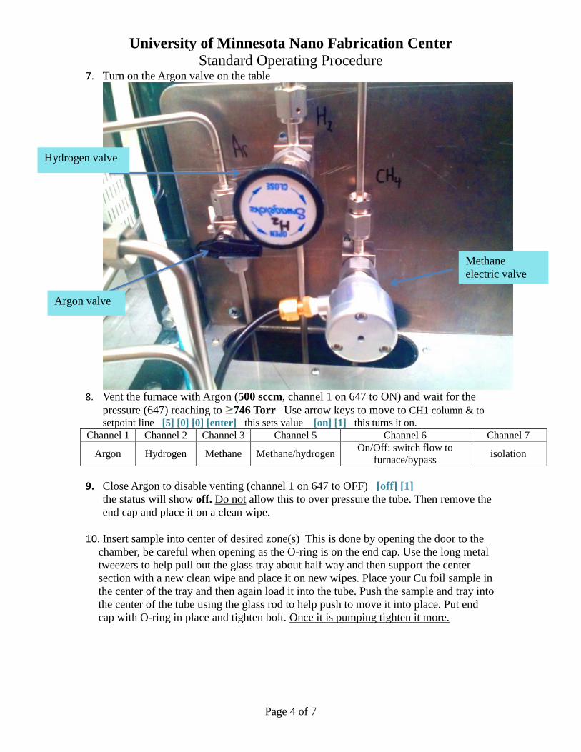
7. Turn on the Argon valve on the table
8. Vent the furnace with Argon (500 sccm, channel 1 on 647 to ON) and wait for the
pressure (647) reaching to 746 Torr Use arrow keys to move to CH1 column & to
setpoint line [5] [0] [0] [enter] this sets value [on] [1] this turns it on.
Channel 1 Channel 2 Channel 3 Channel 5 Channel 6 Channel 7
Argon Hydrogen Methane Methane/hydrogen On/Off: switch flow to
furnace/bypass isolation
9. Close Argon to disable venting (channel 1 on 647 to OFF) [off] [1]
the status will show off. Do not allow this to over pressure the tube. Then remove the
end cap and place it on a clean wipe.
10. Insert sample into center of desired zone(s) This is done by opening the door to the
chamber, be careful when opening as the O-ring is on the end cap. Use the long metal
tweezers to help pull out the glass tray about half way and then support the center
section with a new clean wipe and place it on new wipes. Place your Cu foil sample in
the center of the tray and then again load it into the tube. Push the sample and tray into
the center of the tube using the glass rod to help push to move it into place. Put end
cap with O-ring in place and tighten bolt. Once it is pumping tighten it more.
Hydrogen valve
Argon valve
Methane
electric valve
University of Minnesota Nano Fabrication Center
Standard Operating Procedure
Page 5 of 7
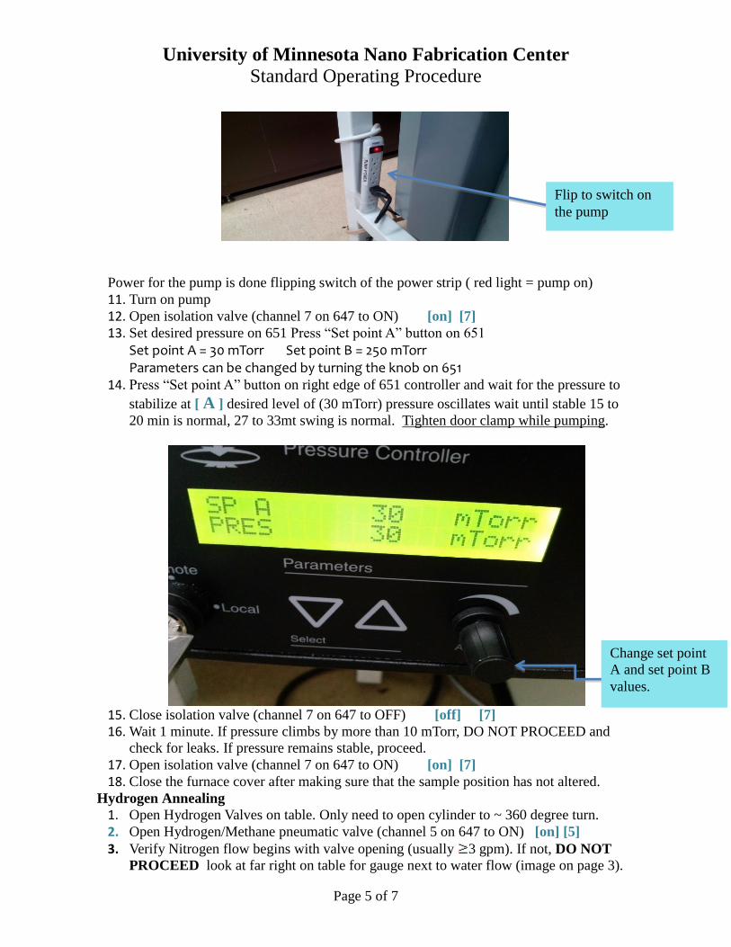
Power for the pump is done flipping switch of the power strip ( red light = pump on)
11. Turn on pump
12. Open isolation valve (channel 7 on 647 to ON) [on] [7]
13. Set desired pressure on 651 Press “Set point A” button on 651
Set point A = 30 mTorr Set point B = 250 mTorr Parameters can be changed by turning the knob on 651
14. Press “Set point A” button on right edge of 651 controller and wait for the pressure to
stabilize at [ A ] desired level of (30 mTorr) pressure oscillates wait until stable 15 to
20 min is normal, 27 to 33mt swing is normal. Tighten door clamp while pumping.
15. Close isolation valve (channel 7 on 647 to OFF) [off] [7]
16. Wait 1 minute. If pressure climbs by more than 10 mTorr, DO NOT PROCEED and
check for leaks. If pressure remains stable, proceed.
17. Open isolation valve (channel 7 on 647 to ON) [on] [7]
18. Close the furnace cover after making sure that the sample position has not altered.
Hydrogen Annealing
1. Open Hydrogen Valves on table. Only need to open cylinder to ~ 360 degree turn.
2. Open Hydrogen/Methane pneumatic valve (channel 5 on 647 to ON) [on] [5]
3. Verify Nitrogen flow begins with valve opening (usually 3 gpm). If not, DO NOT
PROCEED look at far right on table for gauge next to water flow (image on page 3).
Flip to switch on
the pump
Change set point
A and set point B
values.
University of Minnesota Nano Fabrication Center
Standard Operating Procedure
Page 6 of 7
4. Set desired Hydrogen (16 sccm, channel 2 on 647) flow rates for heating step then
turn on Hydrogen flow (channel 2 on 647 to ON) arrow to channel 2 flow []
and [1] [6] [on] [2]
5. Wait 30 seconds for flow to stabilize
6. Wait for the pressure (651) to stabilize at set point A (typically stabilized at 33 mTorr)
7. Switch flow to furnace (channel 6 on 647 to ON) [on] [6]
8. Turn on furnace power supply and set desired temperature (1050C). Alarm must be
cleared on Temperature Limit Switch (center of furnace power supply). Cycle to
display AL 1,by pressing the UP or DOWN until the AL1 is displayed. Then hold Up
or DOWN for ~3 seconds until display reads Clr, then release and press UP or
DOWN again. Alarm should clear and a click sound is made. The temperature set
point can be changed by pressing the UP or DOWN.
9. Temperature ramp rate can be set for each zone. See manuals if new rate desired
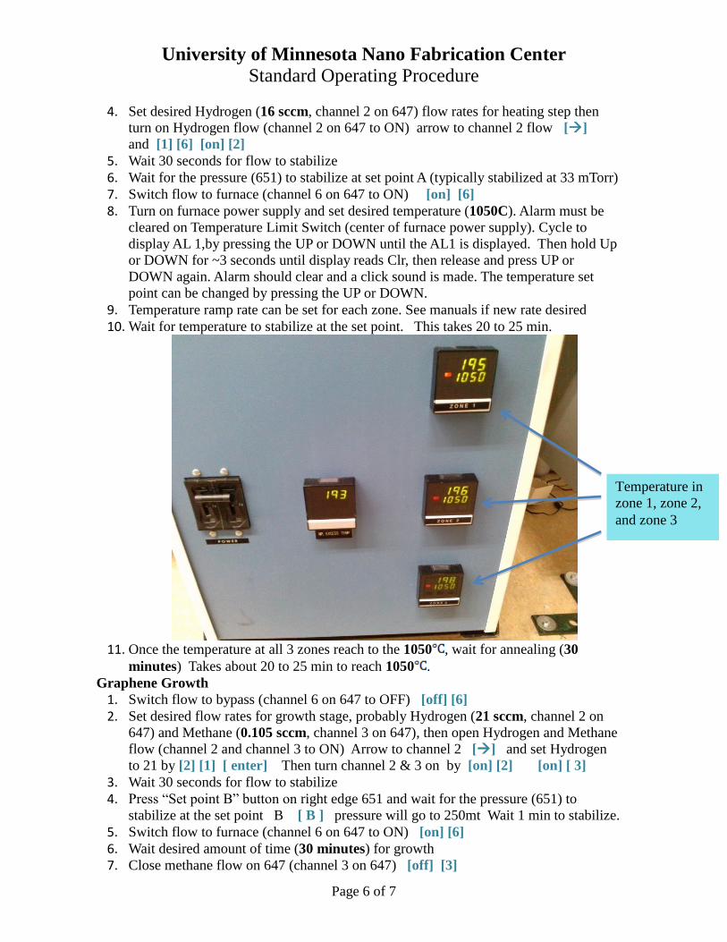
10. Wait for temperature to stabilize at the set point. This takes 20 to 25 min.
11. Once the temperature at all 3 zones reach to the 1050 , wait for annealing (30
minutes) Takes about 20 to 25 min to reach 1050 .
Graphene Growth
1. Switch flow to bypass (channel 6 on 647 to OFF) [off] [6]
2. Set desired flow rates for growth stage, probably Hydrogen (21 sccm, channel 2 on
647) and Methane (0.105 sccm, channel 3 on 647), then open Hydrogen and Methane
flow (channel 2 and channel 3 to ON) Arrow to channel 2 [] and set Hydrogen
to 21 by [2] [1] [ enter] Then turn channel 2 & 3 on by [on] [2] [on] [ 3]
3. Wait 30 seconds for flow to stabilize
4. Press “Set point B” button on right edge 651 and wait for the pressure (651) to
stabilize at the set point B [ B ] pressure will go to 250mt Wait 1 min to stabilize.
5. Switch flow to furnace (channel 6 on 647 to ON) [on] [6]
6. Wait desired amount of time (30 minutes) for growth
7. Close methane flow on 647 (channel 3 on 647) [off] [3]
Temperature in
zone 1, zone 2,
and zone 3
University of Minnesota Nano Fabrication Center
Standard Operating Procedure
Page 7 of 7
8. Set furnace temperature to 0 (or anything below room temperature). Can also cycle
furnace power off and back on to trip default alarm. This way the heating elements
will receive no power while allowing the temperature to still be displayed without
needing to change the set points.
9. Change hydrogen flow to 16 sccm (channel 2 on 647). The pressure will
automatically re-stabilize at 250 mTorr arrow [] channel 2 and [1] [6] [enter]
10. Wait for furnace to cool to at least 300 (approximately 2 hours 40 minutes). You
can then open furnace cover to help speed cooling WAIT until the temperature is 80C.
11. Turn off Hydrogen (channel 2 on 647 to OFF) [off] [ 2 ]
12. Close Hydrogen/Methane pneumatic valve ( 5 on 647 to OFF) [off] [ 5]
13. Close Hydrogen valve on table
14. Close bypass (channel 6 on 647 to OFF) [off] [6]
15. Close isolation valve (channel 7 on 647 to OFF) [off] [7]
16. Set Argon flow rate to 500 sccm on channel 1 and open Argon flow (channel 1 on 647
to ON) [5] [0] [0] [enter] [on] [1]
17. Wait for vent until pressure is 746 Torr. If low pressure sensor was used, will need
to switch to ambient pressure sensor and change setting on 651 appropriately
18. Close Argon (channel 1 on 647 to OFF) [off] [1]
19. Remove sample and reseal process tube System Shutdown
1. Open isolation valve (channel 7 on 647 to ON) [on] [7]
2. Pump system down to minimum pressure (can just wait about 30 seconds rather than
switching to low pressure sensor) under Argon flow of ~10 sccm (set 10 sccm on
channel 1 then channel 1 to ON) [0] [1] [0] [enter] [on] [1]
3. Open 651 valve. Make sure the green LED light is on the open button.
4. Wait for the flow to stabilize, then turn off Argon(channel 1 on 647 to OFF) [off] [1]
5. Close isolation valve (channel 7 on 647 to OFF) [off] [7]
6. Close 651 valve. Make sure the green LED light is on the Close button.
7. Turn off 651 -turning off power switch in back and pump by turning off power strip.
8. Close Argon valve on table above power strip ¼ turn.
9. Close Nitrogen and water valves on table
10. Close cylinder valves for Argon
11. Turn off the furnace power supply main power breaker switch.
12. Turn off 647 flow controller [off] [0/All] (press OFF then 0/ALL, make sure it read
“FLOW OFF”, then on main menu press 0/ALL) ← → to check each line
Press [esc] [0] to shut off 647 system.
13. Verify that all components are turned off (LEL sensor should remain on) 14. Fill in log book and log out of Badger.
8 Appendix