Embed Size (px)
Citation preview

UNIVERSITY OF NAIROBI
DEPARTMENT OF ENVIRONMENTAL AND BIOSYSTEMS ENGINEERING
FEB 540: DESIGN PROJECT
DESIGN OF A LAMP CRUSHER DEVICE FOR SAFE AND EFFICIENT
CAPTURE OF MERCURY VAPOUR FROM FLUORESCENT LAMPS
BY:
YVONNE GATHONI MWANGI
REG. NO: F21/0036/2008
Supervisor:
Dr. Muthumbi Waweru
(April 2013)
A report submitted in partial fulfillment of a Bachelor of Science degree in Environmental and
Biosystems Engineering in the University of Nairobi

2
DECLARATION
I hereby declare that this design project is my original work and has not been submitted for a degree
award or its equivalent in any other university.
Signature………………………………………… Date………………………………………………….
Yvonne G. Mwangi
This design project has been submitted for examination with my approval as a University Supervisor.
Signature………………………………………… Date………………………………………………….
Dr. Muthumbi Waweru

3
DEDICATION
I dedicate this project to all my younger cousins, nieces and nephews. You can do anything you set your
mind to. The sky is the limit.

4
ACKNOWLEDGEMENT
I would like to express my sincere gratitude to my supervisor, Dr. Muthumbi Waweru, who has seen me
through this project. I would also like to recognize Mr. Januarius Agullo for his contribution in the
preparation of the project. I also appreciate all the lecturers of the Department of Environmental &
Biosystems Engineering, beginning with the able chairman, Eng. Dr. Ayub Gitau for their teaching and
mentorship throughout these five years.
I am grateful to my fellow students for their advice and friendship, to my parents, for being my steadfast
encouragers, as well as my financial support, and to God, the Almighty, through whose strength I can do
all things.

5
ABSTRACT
As the world grapples with the issue of global warming, there has been a shift away from energy-
wasting incandescent bulbs to fluorescent lamps, which are more than four times more energy
efficient and last up to 10 times longer. However, mercury is an essential ingredient in
fluorescents and presents a problem when it comes to their disposal or recycling. Mercury in
bulbs is mainly of elemental form, and 17-40% of it exists as a gas. This project was primarily
concerned with capturing this toxic vapour, to prevent its escape into the atmosphere, and its
eventual deposition in lakes and rivers. This was to be done by first crushing the bulbs to release
the mercury vapour, and then directing the mercury laden air into a filter made of activated
carbon, onto which the molecules of mercury would adsorb. A lamp crusher machine was
designed for this purpose consisting of four main components: the carbon filter, the vacuum
pump, the storage structure and the crushing unit. The machine, while designed to serve an
environmental purpose, was also specifically designed to help address the problem faced by the
Anti-Counterfeit Agency, which was storing three full shipping containers of fake fluorescents
that it lacked the means of disposing of in an environmentally safe and legally sanctioned way.

6
Table of Contents 1 Introduction .......................................................................................................................................... 9
1.1 Background ................................................................................................................................... 9
1.2 Problem Statement ..................................................................................................................... 11
1.2.1 Problem Analysis ................................................................................................................. 11
1.3 Objectives.................................................................................................................................... 13
1.3.1 Overall Objective ................................................................................................................. 13
1.3.2 Specific Objectives .............................................................................................................. 13
1.4 Statement of Scope ..................................................................................................................... 14
1.5 Site Analysis ................................................................................................................................ 14
2 Literature Review ................................................................................................................................ 15
3 Theoretical Framework ....................................................................................................................... 24
3.1 Adsorption by Activated Carbon ................................................................................................. 25
3.2 Mercury vapour state ................................................................................................................. 28
3.2.1 Storage Unit ........................................................................................................................ 30
3.2.2 Sizing the motor .................................................................................................................. 31
3.2.3 Vacuum Pump Theory ......................................................................................................... 34
4 Methodology ....................................................................................................................................... 40
4.1.1 Data collection .................................................................................................................... 40
4.1.2 Activated carbon adsorption analysis ................................................................................. 40
4.1.3 Storage Unit sizing .............................................................................................................. 41
4.1.4 Motor sizing ........................................................................................................................ 42
4.1.5 Vacuum pump sizing ........................................................................................................... 43
5 Results and Discussion ........................................................................................................................ 44
5.1.1 Data collection .................................................................................................................... 44
6 Conclusions ......................................................................................................................................... 47
6.1 Recommendations ...................................................................................................................... 47
7 References .......................................................................................................................................... 48
8 Appendices .......................................................................................................................................... 51
8.1 Appendix 1: Design Drawings ..................................................................................................... 51
8.1.1 The Lamp Crusher ............................................................................................................... 51
8.1.2 Crusher Unit ........................................................................................................................ 54

7
8.2 Appendix 2 Design Calculations .................................................................................................. 56
8.2.1 Activated carbon adsorption analysis ................................................................................. 56
8.2.2 Storage Unit sizing .............................................................................................................. 59
8.2.1 Motor sizing ........................................................................................................................ 62
8.2.2 Vacuum Pump ..................................................................................................................... 64
8.3 Appendix 3 .................................................................................................................................. 67
8.3.1 Mechanical properties of Silica Glass.................................................................................. 67
8.3.2 Motor efficiencies ............................................................................................................... 68
8.3.3 Pressure Ranges of Vacuum Pumps .................................................................................... 69

8
LIST OF FIGURES
Figure 1: Fluorescent bulbs: Tube light (left) and Compact Fluorescent Lamp (CFL) ................................... 9
Figure 2: Improper discarding of fluorescent lamps ................................................................................... 16
Figure 3: Different types of drum-top crushers .......................................................................................... 20
Figure 4: Tubes ready for processing at the Balcan plant ........................................................................... 22
Figure 5: The lamp crushing process ........................................................................................................... 24
Figure 6: Vapour adsorbed into pores of adsorbent .................................................................................. 25
Figure 7: Carbon canister ............................................................................................................................ 26
Figure 8: Stress-Strain Curve ....................................................................................................................... 31
Figure 9: Types of vacuum pumps .............................................................................................................. 35
Figure 10: Outer view (left) and principle of operation of a vacuum pump ............................................... 36
LIST OF TABLES
Table 1: Independent Impacts of lamp age at failure, Handling Conditions and Ultimate fate of
Fluorescent Lamps on their Overall Mercury Impacts. ............................................................................... 13
Table 2: Mercury use in lamps sold by NEMA companies in 2004 (IMERC Fact Sheet, 2008) ................... 16
Table 3: Effect of different recycling efficiency on the total environmental release of Hg. (SCHER, 2010)
.................................................................................................................................................................... 17
Table 4: Summary of collected data ........................................................................................................... 44
Table 5: Masses of different lamp types (Source: Environment Canada) .................................................. 58

9
DESIGN OF A LAMP CRUSHER DEVICE FOR SAFE AND EFFICIENT
CAPTURE OF MERCURY VAPOUR FROM FLUORESCENT LAMPS
1 Introduction
1.1 Background
Mercury (chemical symbol: Hg, atomic number 80) is a poisonous metal found in fluorescent
lamps, of which there are two types: tube lights and Compact Fluorescent Lamps (CFLs). When
electricity is passed through mercury vapour in a phosphor tube, it produces short-wave
ultraviolet light which then causes the phosphor to fluoresce, making visible light, unlike in
incandescent bulbs where electric current runs through a wire filament and heats the filament
until it starts to glow. Fluorescents tend to be about four times as energy-efficient as
incandescent bulbs because they require less energy to provide lighting. They are also more cost-
effective because they can last up to 10 times longer.
Figure 1: Fluorescent bulbs: Tube light (left) and Compact Fluorescent Lamp (CFL)
It is due to these advantages that the use of fluorescent bulbs is becoming more widespread as
people try to cut down on energy costs. In 2009, a global initiative to accelerate the uptake of
low energy light bulbs and efficient lighting systems was launched by the Global Environment
Facility (GEF) and the United Nations Environment Programme (UNEP). Known as the
“en.lighten initiative”, it is aimed at reducing the bills of electricity consumers in developing
economies while delivering cuts in emissions of greenhouse gases (UNEP, 2009).

10
However, the presence of mercury in these lights renders them extremely dangerous when burst
or broken. The elemental mercury contained in the bulbs quickly evaporates, particularly in
warm or poorly-ventilated indoor spaces, jeopardizing the ambient air quality. (EPA) According
to the United States Environmental Protection Agency (EPA), air borne mercury is highly toxic
when inhaled, manifesting through tremors, headaches, insomnia, emotional changes and even at
higher exposures, kidney failure and death. At the same time, mercury raises a problem in terms
of lamp disposal. The consequence of carelessly discarding CFLs is the introduction of mercury
into the soil and contamination of groundwater systems. When mercury enters bodies of water,
biological processes transform it to methyl mercury, a highly toxic form. This leads to a
phenomenon called bioaccumulation, as each organism higher up the food chain ingests an
increasing concentration of mercury. Exposures to very small amounts of these compounds can
result in devastating neurological damage and death. For foetuses, infants and children, it impairs
neurological development and impacts cognitive thinking ability, memory, attention, language,
fine motor skills, and visual spatial skills.
Each fluorescent bulb contains trace amounts of this substance, approximately 8-50 mg, but
considering the potential number of these bulbs being used and discarded every day, it is clear
that there is a need to develop a system or equipment for treatment of this waste for the
environmental health of the country. This technology, while not yet being applied in Kenya, is
being used in countries such as the United States of America. It works by separating the mercury
vapour from the crushed glass of the bulb by creating a vacuum to suction the vapour out and
trapping it in a filter, such as activated carbon (Davis, 2006). The filter is removable and can be
replaced when full. The recovered mercury can therefore be utilized in industries that require it
such as dentistry.

11
1.2 Problem Statement
Fluorescent bulbs are energy-efficient alternatives to the long-used incandescent bulbs.
However, the mercury they contain renders the spent bulbs hazardous waste. Due to its volatility,
mercury is emitted into the atmosphere and subsequently deposited in the soil and water bodies.
Technology is therefore necessary which can safely capture the mercury and allow for the safe
recycling or disposal of the glass component. Fluorescent lamp crushers are devices that allow
size reduction for improved storage and transportation of used bulbs, as well as separation of
mercury from the other components of the lights in order to ease disposal.
1.2.1 Problem Analysis
Globally, there has been a move towards increased use of fluorescents as a replacement for
traditional tungsten-filament lights. This makes sense: Some 25% of the energy consumed by
CFLs is converted to visible light, as compared to only 5% for an incandescent lamp. This means
that up to 95% of the energy emitted by incandescent lamps is heat, and their efficiency is
inherently low. Comparing the two types of lighting, incandescent bulbs last around 1,000 hours,
which is significantly shorter than energy saving lamps, with life spans of 6,000 to 12,000 hours.
Use of fluorescent lamps promotes efficient energy use which is a stated goal of Vision 2030
(Vision 2030, p8). While exact numbers on the uptake of CFL are hard to come by in Kenya, it is
a fair assumption that in urban areas at least, penetration rates are already relatively
high. However, this development has not been accompanied by a proper waste recovery
programme. There are no regulations in place specifically regarding the disposal of these bulbs.
The national environmental body NEMA only states that hazardous waste, into which category
spent fluorescents fall, must first undergo treatment to make it innocuous after which it can be
safely disposed of.
The lack of proper regulation means that mercury may still be finding its way into the soil and
into water systems, posing a potential health threat to both animals and human beings. One
fluorescent tube contains enough mercury to pollute 30,000 litres of water beyond safe drinking
level (source: Mercury Recycling plc). Fluorescent and other mercury-containing bulbs often

12
break when thrown into a dustbin, or when they end up in a landfill or incinerator, releasing
mercury vapour that can cause immediate problems like shortness of breath, chest pain, nausea,
vomiting, and vision problems. Once in the atmosphere, elemental mercury can float for over a
year while oxidized mercury compounds could drift several days before precipitating to the
earth: soil or water( Jinjing, 2004). With no way to properly dispose of these lamps, an
alternative is to stack and store spent bulbs in boxes, occupying storage space that might be
otherwise utilized.
Although lighting manufacturers have greatly reduced the amount of mercury used in lighting
over the past 20 years, they are not yet able to completely eliminate the need for mercury.
According to National Electrical Manufacturers Association, (NEMA US) surveys, mercury use
has been reduced dramatically over the last 7 years. Since 1990, NEMA US has conducted a
number of surveys, which indicate the total amount of mercury contained in all lamps in the U.S.
declined to 17 tons in 1994, 13 tons in 1999, 9 tons in 2001 and 7 tons in 2003—nearly a 90%
reduction from previous years. Lamp types with high mercury content are, however, still
reported to be on the market, and may be sold in large quantities as they are generally cheaper
than low-mercury lamps. All this means that there is need for a way to capture mercury from the
lights. The use of lamp crushing to reduce spent fluorescent tube lights helps to free up storage
space, and more importantly, reduce the amount of mercury entering the environment from bulb
disposal. This mercury can then be recycled separately from the other components of the bulbs,
e.g. glass, metal and phosphor.
The table below shows that incinerating fluorescent bulbs carries the highest environment risk,
whereas breaking of the bulbs inside the controlled conditions of a recycling chamber and
recovering the mercury is the safest way of disposing of these bulbs. At the point of release,
mercury concentrations are highest and the conditions for capture most favorable. (Manchester,
2004)

13
Table 1: Independent Impacts of lamp age at failure, Handling Conditions and Ultimate fate of Fluorescent Lamps on their Overall Mercury Impacts.
1.3 Objectives
1.3.1 Overall Objective
The objective of this project was to design a lamp crushing device for the safe capture of
mercury from fluorescent bulbs
1.3.2 Specific Objectives
Establish the quantity of fluorescent lamps being held currently by the Anti-Counterfeit
Agency
Assess current disposal methods of these bulbs
Identify the pertinent physical parameters which the design of the crusher will be based
on.
Design of the lamp crusher using the parameters identified

14
1.4 Statement of Scope Although the topic of mercury recycling is wide and virtually inexhaustible, this particular
project was limited to design of a lamp crusher for primary treatment of spent fluorescent bulbs,
that is, capture of mercury vapour by means of a crusher. These light bulbs are crushed as the
first step in recovery of mercury, or disposal of the bulbs in a landfill or incinerator. This
document does not address the retorting of mercury-containing material for the recovery and
recycling of elemental mercury, or the disposal of mercury-containing wastes, resulting from
crushing operations.
1.5 Site Analysis
The Anti-Counterfeit Agency is a state corporation currently within the Ministry of
Industrialization that was established under the Anti-Counterfeit Act of 2008 with the principal
aim of prohibiting trade in counterfeit goods. The Agency came into operation in June 2010 with
the mandates to enlighten and inform the public on matters relating to counterfeiting, combat
counterfeiting, trade and other dealings in counterfeit goods, devise and promote training
programs to combat counterfeiting and co-ordinate with national, regional or international
organizations involved in combating counterfeiting.
In keeping with its mandate, the Agency has been able to intercept five containers of counterfeit
fluorescent lamps imported into the country from China. The cargo comprised mainly fake
Philips fluorescents of various sizes. Each container weighed between 35 and 40 tonnes and had
an estimated value of KSh 10 million. However, as a result of a court order, two of the seized
containers were returned to their owners. The other three are currently being stored in
warehouses at the Agency’s expense. Two are in Kiang’ombe, Nairobi, and the remaining
container is being stored in Mombasa.
The Agency must continue to store the lamps at a rate of KSh 422,400 annually per container
because the National Environmental Management Agency (NEMA) regulates the disposal of the
bulbs and has yet to license any facility in Kenya to treat and/or dispose of mercury-containing
lamps.

15
2 Literature Review Mercury is volatile. It vapourises at room temperature and increasingly rapidly as temperature
increases. The vapour is an invisible, odourless and tasteless toxic gas. Its difficulty to perceive
with our senses makes it more dangerous, as one may not even realize he is being exposed to it.
Mercury is emitted into the atmosphere from both anthropogenic and natural sources, and
because of its high volatility, subsequently enters oceans, lakes, and rivers directly from the
atmosphere or from deposits in surrounding basins even when no specific source of mercury
exists. (Fitzgerald et al, 1998)
Because of this, mercury-containing devices are classified as hazardous waste in many countries.
Here in Kenya, according to the NEMA-authored Waste Management Regulations, 2006,
Schedule IV, “wastes containing 0.1% or more by weight of…mercury” qualify as hazardous
and must be treated before disposal. Traditional methods of disposal such as landfilling and
incineration fail to take into account the volatility of mercury, resulting in its escape into the
atmosphere and its subsequent deposition in water bodies.
It is for this reason that lamp recycling is the most environmentally sound and preferred disposal
method for spent fluorescent lamps. Fluorescent lamp recycling refers to the reclamation of the
materials of a spent fluorescent lamp. The process prevents the release of mercury into the
environment by recovering it before the lamps are discarded. Although the amount of mercury in
a single fluorescent lamp is small, (see Table 2) collectively, large numbers of fluorescent lamps
contribute to the amount of mercury that is released into the environment. In the United States,
about 620 million fluorescent lamps are discarded annually (National Electrical Manufacturers
Association [NEMA US], 2000); proper recycling of a lamp prevents emission of mercury into
the environment, and is required by most US states for commercial facilities. Landfill space is at
a premium throughout the world and so the less waste that gets landfilled, the better.

16
Table 2: Mercury use in lamps sold by NEMA companies in 2004 (IMERC Fact Sheet, 2008)
Lamp Type Amount of mercury per lamp
(mg)
Per cent of lamps with specified
mercury amount
Fluorescent tube 0 – 5 > 5 – 10 > 10 – 50 > 50 – 100
12 48.5 27 12.5
CFL
0 – 5 > 5 – 10 >10 – 50
66 30 4
High Pressure Sodium
>10 – 50
97
Figure 2: Improper discarding of fluorescent lamps
The biggest motivation for lamp recycling is that it prevents a significant amount of mercury
from entering the environment. The Scientific Committee on Health and Environmental Risks of
the European Union wanted to assess the effect of separate collection (and removal of mercury
i.e. recycling) on the total Hg release into the environment. Assuming that each CFL contained
4.5 mg and that 20% were recycled, and using 2007 sales data, this resulted in a mercury

17
emission in the environment of 1592 kg annually in the EU-27 area. However, increasing the
recycling efficiency to 100% would have the effect of 71% less Hg being released. (SCHER,
2010)
Table 3: Effect of different recycling efficiency on the total environmental release of Hg. (SCHER, 2010)
Recycling efficiency (%)
Hg content of CFL (mg) Hg release in environment (kg/y)
20 4.5 1592
50 4.5 1027
100 4.5 462
Virtually all components that make up fluorescent lights, including metal end caps, glass tubing,
and phosphor powder, can be separated and recycled: The recycled glass tubing can be
remanufactured into other glass products e.g. glass wool insulation; brass and aluminium in end
caps is often sold as scrap metal; the internal phosphor coating can be reprocessed for use in
paint pigments and as a bulking agent for fertiliser and the mercury contained in the lamp can be
reclaimed and used in new lamps and other mercury-containing devices as well as a dental
amalgam. The actual scrap value of the materials salvaged from a discarded lamp is insufficient
to offset the cost of recycling which forces recyclers to charge fees for their services.
Many developed nations have recycling programs. Responsibility for recycling may fall on the
municipal or state authorities, lamp producers, distributors or consumers. Common lamp
recycling programs in the United States and in other countries include:
Consumer mail-back programs, such as manufacturer and lamp recycler-sponsored
recycling kits;
Retail-sponsored collection programs at hardware and other stores, wholesale facilities,
and other commercial locations;
Utility-sponsored collection programs at a variety of locations;
Publically-sponsored collection programs, such as household hazardous waste (HHW)
collection facilities, municipal collection sites, and curbside recycling services; and

18
Extended producer responsibility programs, such as the Waste Electrical and Electronic
Equipment (WEEE) initiative in Europe, and similar programs in Asia. The WEEE
directive requires producer responsibility for end-of-life management of certain products
that contain mercury, lead, cadmium, chromium, and flame retardants like
polybrominated biphenyls (PBB).
A mandatory lamp recycling program was instituted in Taiwan in 2002 by the Taiwan
Environmental Protection Administration. Under the program, consumers can recycle lamps in
any shop that sells them, and the collected lamps are sent to one of four mercury reclamation
facilities. In 2003, about 87% of lamps were recycled in Taiwan (Hilken, C & Friesen, K, 2005).
If each of those 78 million lamps had 5mg of mercury, this means that approximately 860
pounds of mercury was recovered.
Once at the recycling centres, the lamps undergo the following process:
1. Material feeding - certified waste fluorescent light tube are placed on a roller conveyer
for further handling.
2. End cutting - The two ends of fluorescent light tubes are cut by flame or knives to
separate fluorescent light tube and light cap. Since light tubes are damaged and mercury
vapor is dispersed, machinery must be equipped with an exhaust system to pump mercury
vapor to activated carbon absorption equipment. The separated cap is classified into three
types of magnetic metal, non-magnetic mental, and lead (tube end) glass.
3. Air jet cleaning - High-pressure air is used to clean mercury from fluorescent powder and
pump fluorescent powder to collection equipment for storage and then to mercury
distillation equipment.
4. Grinding and Screening -This process includes tube end grinding and tube grinding.
Tube end grinding uses a large machine to cut the end of the lighting product for the
convenience of packaging and transportation operations afterwards. Magnetic and
vibrating screening is done to sort copper, aluminum, and iron material out.
5. Follow-up Treatment - After handling, waste fluorescent light tubes generate six types of
materials, tube (sodium) glass, tube end (lead) glass, fluorescent powder, mercury, iron,
copper and aluminum. Fluorescent powder and end glass are sent to landfills; some tube
19
glass is landfilled, but the majority is recycled for re-utilization. Magnetic metal is also
handled for reuse.
The Japan Fluorescent Lamp Recycling Company Ltd. uses “March 21” fluorescent lamp
recycling equipment in its facilities. “March 21” is a recycling system that turns mercury into
steam at a low temperature and recovering it. The boiling point of mercury is approximately
356.58℃, and high-temperature equipment of over 700℃ is normally required to convert
mercury into steam and recover it. However, this technology can turn mercury into steam at
lower temperatures between 250℃ and 300℃. Additionally, indirectly applying heated air to the
rotary kiln can keep glass, aluminum and plastic substances from melting and sticking together,
which can prevent the process from generating dioxin. (See Appendix 3 for process flowchart)
On a slightly smaller scale, one can employ crushing. The crushing of fluorescent lamps to
separate the glass from the phosphor powder in the lamp is commonly the first step in recycling
of mercury; although some companies use other methods, such as removal of the phosphor
powder by air vortex or by flushing with hydrochloric acid. (Truesdale et al, 1993)
Drum-top crushing (DTC) is usually employed at the point where lamps are removed from
service. DTC devices are designed to fit on the top of a drum (hence the name) in order to
prevent the release of mercury vapours while crushing the fluorescent lamps into the drum
below. These devices are used to reduce the volume of waste lamps so as to improve storage and
handling and reduce shipping costs associated with fluorescent lamp recycling.
Lamp crushing is considered waste treatment because it changes the physical form of the waste
and reduces volume to make storage and transport safer and easier. The most common type of
crusher is the drum-top crusher (DTC). It consists of a vacuum-sealed container – a 55-gallon
(210 litre) steel drum – in which glass fragments collect after passing through an entry tube and
crushing mechanism. The mercury content of the lamp is contained by the vacuum and trapped
in a filter arrangement, which must be replaced periodically. Spent fluorescent lamps are
typically hand-fed into the entry tube, rapidly drawn into the drum by the vacuum seal and
crushed in the motorized crushing assembly. Once the storage container is full, it is replaced and
shipped to a recycling facility for processing. Mercury released as a vapour is collected in a
distillation unit for sale or reuse. Secondary treatment might then include lamp retort (heating)

20
to recover any mercury trapped in the crushed glass. Several companies manufacture fluorescent
lamp crushers, including Dextrite, Air Cycle Corporation, and Resource Technologies. Drum-top
lamp crushers are designed for use primarily in commercial and institutional facility management
contexts.
Figure 3: Different types of drum-top crushers
The American Environmental Protection Agency (EPA) recently completed a drum-top crusher
(DTC) study (EPA, 2006). The study was performed at three large-scale lamp-recycling facilities
and evaluated the performance of three DTC devices. It showed that the performances of the
devices diminished over their lifetimes and under varying environmental conditions. Minor
mistakes in assembly of the devices could result in leaks. The effectiveness of the three devices
in capturing and retaining mercury was evaluated using a mass balance. This was expressed as a
percent of the total mass of mercury fed into the DTC device. For each device, the total mercury
contained in enough lamps to fill one drum was estimated, and this quantity was then compared with
the total mercury detected in samples collected during testing including: crushed lamps from the
drum, DTC pollution control media (particulate, HEPA, and carbon filters), and analytical air
samples. From the results, it appeared the efficiency of the lamp crushers was directly proportional to
the mass of carbon used in the filter.

21
One major disadvantage was that the drums could only accommodate a certain number of lamps
before they needed to be changed. When the drum beneath a DTC device was filled with crushed
lamps, the DTC device had to be secured to a new drum. This operation involved unsealing the
DTC device from the drum, lifting it off the drum, and placing it on a new, empty drum. During
this operation, the full drum of crushed lamps would be open to the air for some period of time
(approximately two to 10 minutes) during which mercury vapor is released uncontrolled to the
air. During the process of changing from a full drum to an empty one, there existed opportunities
for additional exposure of the operator to mercury vapour. Thus, by reducing the frequency of
changes and/or minimizing the time during which the full drum is open to the air, one would be
able to limit mercury exposure. Nevertheless, throughout the study, all three devices maintained
mercury levels below Occupational Safety and Health Administration (OSHA) time-weighted
average requirements within the containment structure and in the operator breathing zone.
There are companies that specialize in lamp recycling such as the UK-based, Balcan
Engineering. The Balcan recycling plant in Lincolnshire can process approximately 750 tonnes
of waste lamps per annum. It has products varying from devices for specific types of bulb
recycling to fully-fledged recycling plants. The recycling plant essentially utilizes the lamp
crusher method, but on a much larger scale. It works like this: Whole and pre-crushed
fluorescent tubes are input into a hopper. From there, they move to an agitator where they are
reduced in size and from which glass and aluminum are separated. The agitation of pieces
knocking and rubbing against each other removes much of the adhering powder from the surface
of the glass. The remaining debris is passed through the Dust Removal Filter which draws off the
dusty air (comprising of phosphor powder and fine glass particles) down to 5-micron size. This
also ensures that the whole plant operates under negative pressure so dust and vapour does not
escape into the workplace. Finally, the Activated Carbon Stack which is used to remove
exceptionally fine dust below 5-microns and mercury bearing vapour (that cannot be removed
from the air in any other way) before release to the outside atmosphere.

22
Figure 4: Tubes ready for processing at the Balcan plant
In addition, Balcan operates a fleet of vans, each fitted with an electrically operated crusher. The
mobile crushers use a fan-assisted filtration unit to draw off the dust during crushing. In this way
the machine also operates at negative pressure. The extractor is positioned in the chute because
fluorescent tubes can inadvertently burst anywhere along their length so it is essential to capture
the resultant dust as it is generated. Balcan has added a spring-loaded sealing plate to their
mobile crushing equipment which is designed to prevent escape of mercury vapour during the
crushing process. Debris from the crushers discharges directly into strong plastic sacks holding
an average of 25-27 kg of debris. And the recycling operation as described previously begins
when the debris sacks are emptied into a hopper at the plant.
Another method of treating lamps is to combine the mercury with sulphur to form mercury
sulphide, which is insoluble in water (Gorin et al., 1994). One advantage of sulphur is its low
cost. The reaction is shown with the equation:
Hg + S → HgS
23
The easiest way to combine sulphur and mercury is to cover a group of fluorescent tubes with
sulphur dust and break them; when the glass is put into a bag to continue with the reaction, the
mercury will combine with sulphur without any other action. The glass can be recycled where an
appropriate facility exists. A quantity of 25 kg of dust sulphur is enough for 1000 tubes.
Research on the subject of lamp recycling is still on-going. Engineers from Brown University
tested 28 different chemicals to collect spilled mercury from CFL breaks. The best performer
was amorphous nanoselenium particles no more than 60 billionths of a meter in diameter. In lab
tests, the orange nanoparticles trapped and neutralized 99.9 per cent of the mercury vapor they
encountered (Hurt, 2009). They proved so potent that just a few milligrams rendered inert a
milligram of mercury — an amount comparable to what a broken CFL would release. In
comparison, quantities in excess of 10 kilograms of powdered sulfur or zinc would be needed to
neutralize a milligram of mercury.
Lamp recycling is a wide field with many players and nearly as many available methods. Each
method of recycling has potential benefits and draw-backs. This project, however, will focus on
the design of a lamp crusher for capture of mercury from fluorescent bulbs.

24
3 Theoretical Framework
Figure 5: The lamp crushing process
The major components of the device are:
1) Activated carbon filter –adsorbs mercury from air within crusher
2) The storage unit – into which the glass and metal parts fall
3) The vacuum pump – lowers the pressure inside the device and directs air
containing mercury vapour into filter
4) The crusher unit – motor, rotor and chains to break the lamps
MERCURY LADEN AIR

25
3.1 Adsorption by Activated Carbon
During the process of adsorption, the gas stream passes through a bed or layer of highly porous
material called the adsorbent. The compound or compounds to be removed, termed the
adsorbate(s), diffuse to the surface of the adsorbent and are retained because of weak attractive
forces, while the carrier gas passes through the bed without being adsorbed.
The adsorption process is classified as either physical or chemical. In physical adsorption, the
molecules are retained at the surface in the liquid state because of intermolecular or Van der
Waals forces. The chemical nature of the adsorbed gas remains unchanged; therefore, physical
adsorption is a readily reversible process. In chemical adsorption a strong chemical bond is
formed between the gas molecule and adsorbent. Chemical adsorption, or chemisorptions, is not
easily reversed.
Figure 6: Vapour adsorbed into pores of adsorbent
Carbon is a commonly used adsorbent due to its very large surface area (500 to 1,600 m2/g). It
can be made from a variety of base materials including coal, wood and coconut shells and
petroleum-based products, and is manufactured in two steps: First, the raw material is pyrolized
i.e. it is heated to about 5900C in the absence of oxygen to drive off all volatile material. Next, it
is activated using steam, oxygen or carbon dioxide at high temperatures to attack the carbon and
increase the pore structure.

26
Activated carbons used in the air pollution control field are normally supplied in a granular form
with a particle size ranging from 1 to 5 millimeters. In the granular form activated carbon can
easily be packed into a containment device through which a contaminated gas stream can be
processed for purification. Most adsorption systems consist of one or more vessels connected in
series or in parallel. These vessels can be cartridges, canisters, drums, tanks, or bins.
Figure 7: Carbon canister
There are three things that are necessary for adsorption of mercury using activated carbon:
1. Containment device – a drum or vessel
2. Distribution and collection devices – for proper circulation of gas stream through filter
bed
3. Means of moving the gas through the means for moving the gas stream through the bed
(such as a fan, a blower, or pressurized gas displacement
Each adsorbing material has a different adsorption capacity referred to as the “adsorption
isotherm.” The adsorption capacity for a particular contaminant represents the amount of the
contaminant that can be adsorbed on a unit weight of activated carbon consumed at the
conditions present in the application until breakthrough occurs. This isotherm is a function of the

27
contaminant concentration (or partial pressure) in the vapor, the temperature, the total ambient
pressure, and the surface area of the carbon.
Adsorption also depends on the gas velocity – the lower the velocity, the longer the contact time
through the adsorbent and the greater the probability of a contaminant molecule reaching an
available site. Appropriate velocities run from 6-30m/min.
To determine velocity:
⁄ ⁄
Once the activated carbon has become spent it must be removed from service and replaced with
fresh carbon in order to maintain the effectiveness of treatment. The spent carbon can be
disposed of and replaced with virgin carbon, or the spent carbon can be returned to the supplier
for reactivation and reuse. The process of removing the adsorbent is called regeneration of the
adsorbate. It is done by either increasing the temperature or decreasing the pressure. It must be
noted that, in practical applications, adsorbers use more carbon than is required at saturation to
ensure that uncaptured vapors are not exhausted to the atmosphere.
There is no theoretical method that consistently and accurately predicts the performance of
adsorption systems (Rafson 1998). Carbon adsorption is based on the principle of equilibrium
partitioning from the vapor phase to the surface of the carbon. The carbon adsorption capacity is
strongly influenced by the contaminant concentration in the process stream and the temperature
at which the adsorption is taking place. In general, the higher the concentration of contaminant in
the vapor stream, the higher the contaminant adsorption capacity of the carbon. Conversely, the
higher the temperature, the lower the adsorption capacity. (Jinjing, 2004) Most carbon
manufacturers have empirical adsorption isotherm data (adsorption capacity as a function of
concentration at a constant temperature) used to predict when the adsorption capacity of a
particular adsorbent will be reached for specific contaminants at varying influent concentrations.
28
3.2 Mercury vapour state
Mercury can exist in 3 states of matter: Liquid, Solid and Gas. It has freezing point of -38.9°C
(234K) and a boiling point of 356.58°C (630K). Standard values are used for mercury molecular
weight (200.6), density (13.5 g/cm3), and vapor pressure (0.0018 mm at 298°K).
It is the only metal that exists as a liquid at room temperature and pressure. In fluorescent bulbs,
mercury is used to convert electrical energy to radiant energy in the ultraviolet range, which is
then re-radiated in the visible spectrum by the “phosphor” compounds that coat the inside of the
bulb.
Mercury exists in elemental form (Hg0) as a silver-colored liquid, or as mercury vapor in the
atmosphere (Schroeder, 1982). Many forms of mercury, including elemental, are volatile enough
so that a significant portion can exist in the gaseous state. Once a CFL has been broken, mercury
vapor, liquid mercury (if present), and mercury adsorbed onto the phosphor powder will be
released. It is unlikely that any spilled liquid mercury will be visible as the volume of mercury is
small and any spilled mercury would form minute droplets on impact. The phosphor powder can
separate from the glass when the lamp is broken. Although it is believed that most of the volatile
mercury in the bulbs is elemental, other volatile mercury compounds and powders may be
released.
The air reaching the activated carbon will be a mixture of a number of gases, including the gas of
interest in this project: mercury vapour. To obtain the partial pressure of mercury vapour, we
must consider Dalton’s Law:
The pressure of a mixture of gases is equal to the sum of the partial pressure of the constituents.
The partial pressure of each constituent is that pressure which the gas would exert if it alone
occupied that volume occupied by the mixture at the same temperature and pressure.
29
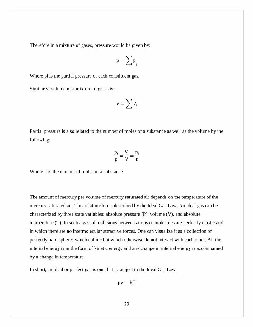
Therefore in a mixture of gases, pressure would be given by:
∑
Where pi is the partial pressure of each constituent gas.
Similarly, volume of a mixture of gases is:
∑
Partial pressure is also related to the number of moles of a substance as well as the volume by the
following:
Where n is the number of moles of a substance.
The amount of mercury per volume of mercury saturated air depends on the temperature of the
mercury saturated air. This relationship is described by the Ideal Gas Law. An ideal gas can be
characterized by three state variables: absolute pressure (P), volume (V), and absolute
temperature (T). In such a gas, all collisions between atoms or molecules are perfectly elastic and
in which there are no intermolecular attractive forces. One can visualize it as a collection of
perfectly hard spheres which collide but which otherwise do not interact with each other. All the
internal energy is in the form of kinetic energy and any change in internal energy is accompanied
by a change in temperature.
In short, an ideal or perfect gas is one that is subject to the Ideal Gas Law.

30
Where:
p= absolute pressure (bar)
R = specific gas constant (Nm/Kg K or kJ/Kg K)
T = temperature (0C)
v = specific volume (m3/kg)
For a mass, m, occupying a volume, V, the equation may be written as:
In terms of the amount of substance (mole), the law becomes:
Where:
n = amount of substance (mol or kmol)
=molar mass (kg/kmol)
3.2.1 Storage Unit
This is where the lamp debris fall after crushing. Its volume will depend on the number of lamps
to be crushed and will be calculated by:

31
3.2.2 Sizing the motor
3.2.2.1 Failure of Materials
The behavior of materials can be broadly classified into two categories; brittle and ductile. Steel
and aluminum usually fall in the class of ductile materials. Glass and cast iron fall in the class of
brittle materials. Every material will perform differently under the application of stress and strain
and therefore each material's graph will be different. considerable amounts of information can be
identified and collected from a Stress-Strain graph.
Figure 8: Stress-Strain Curve
Some of the graph's most important aspects are:
The elastic region -For most materials the elastic region is illustrated by the initial
straight line
Yield stress
Plastic flow region- The plastic flow region is illustrated by the curved line that ends
at the "rupture stress" point.
Ultimate stress (UTS) -The ultimate tensile stress is the maximum stress recorded
throughout the continued stress application.
The rupture stress is the maximum instantaneous stress at the breaking point of the
material.

32
After the yield point, the curve will dip slightly then the stress will increase because of strain
hardening. Finally, the graph will reach its ultimate tensile strength. Hence forth the material
becomes unstable and fractures.
The material response for ductile and brittle materials is exhibited by both qualitative and
quantitative differences in their respective stress-strain curves. Ductile materials will withstand
large strains before the specimen ruptures; brittle materials fracture at much lower strains. The
yielding region for ductile materials often takes up the majority of the stress-strain curve,
whereas for brittle materials it is nearly nonexistent. Brittle materials often have relatively large
Young's moduli and ultimate stresses in comparison to ductile materials. Their rupture and
ultimate strength is the same, so the curve has only the straight elastic region then the rupture.
These differences are a major consideration for design. Ductile materials exhibit large strains and
yielding before they fail. On the contrary, brittle materials fail suddenly and without much
warning.
Stress, is the force per unit area (N/m2)
Whereas strain is the relative change in shape or size of an object due to externally applied
forces;
The two are related by Young’s modulus:
3.2.2.2 Newton’s Laws of Motion
Mechanics is governed by Newton’s Laws of Motion:
1. Every object in a state of uniform motion tends to remain in that state of motion unless an
external force is applied to it (Law of Inertia)

33
2. The change of momentum per second is proportional to the applied force and the
momentum change takes place in the direction of the force. (F = ma).
3. For every action there is an equal and opposite reaction.
The crusher unit is made up of the motor, which runs the rotor-and-chains that actually shatter
the lamps. In order to design a system which can effectively crush the lamps, we must consider
the torque and angular acceleration of the chains, and the moment of inertia.
The angular acceleration of an object spinning about its centre is given by:
Where ω final angular velocity; ω0= initial velocity; t = time
To make the wheel spin faster, a torque, T is applied to the wheel. The turning effect or torque of
a force, F applied tangentially to a wheel of radius, r spinning about its centre is given by T = F
× r (Nm). According to Newton’s second law, F ma. In rotational motion, this can be
analogized as:
Where I is the moment of inertia. The moment of inertia, I , of a rigid body gives a measure of
the amount of resistance a body has to changing its state of rotational motion. Mathematically,
∑ (kg m
2)
i.e. the sum of all the products mr2 for the masses m of the object and the square of their
distances from the axis of rotation.

34
Once the torque, angular acceleration have been determined, a motor that provides the necessary
operating speed and load torque can be obtained. An electric motor is a device that converts
electrical energy into mechanical energy. Electric motors convert voltage into speed and current
into torque:
Calculating torque
Torque (in Newton-metres) is given by:
Kt I
Where:
Kt= constant
Ia= armature current (Amperes)
Calculating speed
ω Kb*V
where V = supply voltage; Kb = constant
The product of the torque and the speed of the motor gives the power:
(Kw)
3.2.3 Vacuum Pump Theory
While in operation, most lamp crusher systems are designed to provide a negative pressure in the
collection container to prevent the release of mercury and dust into the ambient air. A vacuum
pump is a device that achieves this by removing gas molecules from a sealed volume in order to
leave behind a partial vacuum.

35
Figure 9: Types of vacuum pumps
3.2.3.1 Vacuum Pumps: Basic Operation
A vacuum pump converts the mechanical input energy of a rotating shaft into pneumatic energy
by evacuating the air contained within a system. The internal pressure level thus becomes lower
than that of the outside atmosphere. The amount of energy produced depends on the volume
evacuated and the pressure difference produced.
Rotary positive displacement pumps are the most effective for low vacuums. Positive
displacement refers to the fact that during operation the pump periodically creates increasing and
decreasing volume to remove gases from the system and exhausts them into the atmosphere. The
rotor is eccentrically mounted in the stator and carries two blades which sweep the space
between the rotor and the stator. (Fig.9b) The gas being exhausted enters through the vacuum
connection and is compressed before delivery through the discharge valve. The efficiency is
impaired by the presence of condensible vapours. Condensible vapours can only be compressed
to their saturated vapour pressure. Further compression will not increase the pressure of the gas.

36
Figure 10: Outer view (left) and principle of operation of a vacuum pump
3.2.3.2 Positive Displacement Vacuum Pumps
Vacuum pumps are either positive displacement or nonpositive displacement machines. A
positive displacement pump draws a relatively constant volume of air despite variations in the
vacuum levels.
Reciprocating Piston Pumps -The primary advantage of the piston design is that it can
generate relatively high vacuums from 27 to 28.5 in. Hg (0.91-0.97 bar) -and do so
continuously under all kinds of operating conditions. The major disadvantages are
somewhat limited capacities and high noise levels, accompanied by vibrations that may
be transmitted to the base structure. In general, the reciprocating piston design is best
suited to pulling relatively small volumes of air through a high vacuum range.
Diaphragm Pumps -The diaphragm unit creates vacuum by flexing of a diaphragm
inside a closed chamber. Small diaphragm pumps are built in both one- and two-stage
versions. The single stage design provides vacuums up to 24 in. Hg (0.81 bar), while the
two stage unit is rated for 29 in. Hg (0.98 bar).
Rocking Piston Pumps -This design combines the light weight and compact size of the
diaphragm unit with the vacuum capabilities of reciprocating piston units. Vacuums to
27.5 in. Hg (0.93 bar) are available with a single stage; two-stage units can provide
vacuums to 29 in. Hg (0.98 bar). Air flows, however, are limited, with the largest model
available today (a twin cylinder model) offering only 2.7 cfm.

37
Rotary Vane Pumps -Most rotary vane pumps have lower vacuum ratings than can be
obtained with the piston design: only 20 to 28 in. Hg maximum (0.68–0.95 bar). But
there are exceptions. Some two stage oil-lubricated designs have vacuum capabilities up
to 29.5 in. Hg. The rotary vane design offers significant advantages: compactness; larger
flow capacities for a given size; lower cost (about 50 percent less for a given
displacement and vacuum level); lower starting and running torques; and quiet, smooth,
vibration free, continuous air evacuation without a receiver tank.
Rotary Screw and Lobed Rotor Pumps - Vacuum capabilities of rotary screw pumps
are similar to those of piston pumps, but evacuation is nearly pulse-free. Lobed rotor
vacuum pumps, like the corresponding compressors, bridge the gap between positive and
nonpositive displacement units. Air flow is high but vacuum capabilities are limited to
about 15 in. Hg (0.5 bar). Capabilities can be improved with staging.
3.2.3.3 Nonpositive Displacement Vacuum Pumps
Nonpositive displacement vacuum pumps which include centrifugal, axial-flow, and regenerative
designs, use changes in kinetic energy to remove air from a system. The most significant
advantage of this design is its ability to provide very-high-volume flow rates-much higher than
possible with any of the positive displacement designs. But because of their inherent leakage,
these machines are not practical for applications requiring higher vacuum levels and low flow
rates.
For a rotary vane pump, the volumetric flow rate at which gas is swept around the pump is:
Where: V = volume of gas between the rotating blades or vanes
n= no. of rotations per unit time (rpm) (usually 350-700 r.p.m.).
The compression ratio is the ratio of the pressure of the exhaust gas (atmospheric pressure) to the
pressure of the gas at the inlet (base pressure) i.e.
⁄

38
Vacuum pumps have two operating characteristics: base pressure and pumping speed.
The speed listed on any given pump is usually the free air displacement at STP. As pressure
decreases from atmospheric, there will be a reduction in the amount of gas pumped per unit time
(mass flow rate). Pumping speed will decrease only slightly until a pressure of about 1 Torr is
attained.
Speed can be measured at constant volume by the equation:
[( ⁄ ) ⁄ ]
Where: V = volume of vessel (litres)
T1 = time at pressure P1(sec)
T2 = time taken to achieve pressure P2 from P1 (sec)
Constant pressure method:
Where:P = pressure (Torr); S = speed (litres/sec); Q = mass flow rate (Torr-litres/sec)
Quantity of gas removed by the pump at a steady state pressure, P, is the mass flow rate of the
gas, or throughput.
Evacuation Time
The evacuation time of a pump is the time taken to evacuate the system from initial pressure to a
final pressure.
Inlet Outlet
PUMP
Gas
39
It is given by the equation:
Where: V = volume of vessel (m3)
P0 = initial pressure (bar)
P2 = final pressure (bar)
S= actual suction capacity (m3/min)
Conductance
Gases moving through conductance elements (pipes, tubes, vessels, and orifices) in a vacuum
system encounter resistance to their motion. At higher pressures, this resistance is a function
pressure difference and geometry of the conductance element.
⁄
P1, P2 are as shown in the figure above.

40
4 Methodology
4.1.1 Data collection
Data regarding the number and fate of fluorescent bulbs at the site were obtained by desk study
and interview. Policy and legal data regarding the fate of fluorescent lamp waste was obtained
from the National Environmental Management Authority (NEMA) again by desk study and
interview with various officers.
4.1.2 Activated carbon adsorption analysis
The adsorptive capacity of the activated carbon was found and used to determine the number of
lamps that could be crushed before the carbon would have to be replaced.
The number of bulbs required to saturate the activated carbon was given by:
To obtain the time before activated carbon reached saturation capacity, The amount of mercury
entering the system every minute is was estimated by:
Where m = mass of activated carbon entering the system per minute
R= rate of feeding bulbs
M= mass of Hg vapour per bulb
So to saturate the carbon at this mass flow rate would take time, t:
In hours:

41
The rate at which the bulbs existing at the site would be processed through the crusher was then
determined.
Number of lamps crushed per day:
Using the relative volumes therefore, the number of lamps per container was estimated as:
Time taken process all the lamps in one container:
4.1.3 Storage Unit sizing
The volume of the storage unit was then calculated, keeping in mind that the bulbs were to be
crushed and stored in batches. The volume of one batch was used to size the unit.

42
The section was divided into two shapes whose volumes could be easily calculated.
So the volume of the rectangular section was:
And the volume of the triangular section was:
4.1.4 Motor sizing
The first step in this process was finding out how much force would be required to break the
glass. Now glass is a brittle material, such that it yields very quickly under a load. Because the
glass would break by shearing the shear strength was pertinent.
This strength was used to find the force required to shatter the glass, which in turn was used to
find the torque required by the motor.
Using IEC standard motor curves, the torque was related to the synchronous speed.
The product of the torque and the speed of the motor gave the power:
(Kw)
If power output is measured in Watt, efficiency can be expressed as:
(1)
Where ηm = motor efficiency
Pout = shaft power out (Watt, W)
Pin = electric power in to the motor (Watt, W)
43
The efficiency was also based on IEC standards. International Electrotechnical Commission
(IEC), a global non-governmental organization that prepares and publishes international
standards for electrical, electronic and related technologies. Several of its standards are highly
relevant for motor manufacturing. IEC 60034 is referred to by regulators for the classification of
electrical motor efficiency.
4.1.5 Vacuum pump sizing
The vacuum pump was sized for the required pressure using by rearranging the evacuation time
equation
such that S (Pump capacity) became the subject:
This value of S, also known as the volumetric flow rate, was then used to calculate the mass flow
rate of the fluid (air) using the equation:
Where Q represents the mass flow rate.
Finally, the power of the pump required was obtained from a commercial power-vacuum curve
since it varies from manufacturer to manufacturers.
They observe

44
5 Results and Discussion For the design calculations, please see Appendix 2
5.1.1 Data collection
The Anti-Counterfeit Agency is the authority in Kenya mandated with preventing the sale of
counterfeit goods in the country. By means of desk study as well as interviews with a
representative of the Agency, I was able to determine that since 2011, they had intercepted five
Chinese-sourced shipping containers of fake fluorescent bulbs destined for sale on the Kenyan
market. However, as at the time of the interview, two of the containers had been returned to their
owner through court order. The rest are being warehoused in Mombasa and Nairobi. Below is a
summary of the information contained and subsequently used in the analysis.
Table 4: Summary of collected data
Number of containers in Storage 3
Mass of each container 30-35 tonnes
Outside dimensions of each container Outside
Length: 12.2m /
40ft
Outside
Height: 2.6m / 8ft
6in
Outside
Width: 2.44m /
8ft
Inside dimensions
Internal
Length: 12.04m / 39ft
6in
Internal
Height: 2.39m / 7ft
10in
Internal
Width: 2.35m / 7ft
8in
Cubic capacity: 67.6 cubic meters
Type of lamps in container Philips fluorescents, assorted sizes
Annual cost of storage per container KSh 422, 400
Note: All the calculations assumed that the sizes of lamps were all 4-foot lamps. This is because
generally, the 4-foot lamp is the highest volume lamp sold, (Environment Canada,2001)
accounting for approximately 75 percent of the market

45
A typical fluorescent bulb discarded today is likely to contain an average of approximately 20
mg mercury (Environment Canada, 2001) where the mercury in vapour form is between 17 and
40% (Aucott, 2004). This information was useful in determining the rate at which activated
carbon would be used up. By calculation, this was found to be 26 days or once per every 250000
bulbs. It is important to note that this was for 10kg of activated carbon with an adsorbent
capacity of 15%. The rate of replacement is primarily a function of the absorbency of the
charcoal.
The rate of crushing the bulbs was over 9600 a day, meaning that the entire confiscated shipment
could be destroyed in 36 days. Compare this with the fact that the oldest container had been
stored since 2011, more than 700 days, and it is clear what the advantages of the lamp crusher
are.
The next step taken was to work out the storage unit volume. The storage unit is where the debris
from crushing falls whilst the mercury-laden air is drawn into the activated carbon filter. The
crushed glass, phosphor and metal end caps are stored for a time before being collected for
disposal or recycling. Typically, the crusher reduces the volume 6-8 times for whole lamps
(MRT Technologies). A convenient value of 10000 lamps per batch was chosen to ease
calculation. The volume of the whole lamps was found, then divided by a factor of 6 to represent
the volume reduction. The final volume was 1.03m3 and the crusher was to have dimensions of
1.5×1m. The height varied due to the slope of the floor of the structure. These dimensions are
reflected in Drawings in Appendix 1 in centimetres to the nearest whole number for ease of
measurement. The storage unit would ideally be constructed of a hard material to resist wear by
abrasion from glass shards – sheet metal such as mild steel.
Following this, the motor that would be able to perform the task of crushing the bulbs had to be
chosen. The first step in this process was finding out how much force would be required to break
the glass. Now glass is a brittle material, such that it yields very quickly under a load. Because
the glass would break by shearing the shear strength was pertinent. This was obtained from a
table of properties (Appendix 3) of silica glass, the type of glass used for such tube lights, as
70000N/m2. This strength was used to find the force required to shatter the glass, which in turn
was used to find the torque required by the motor. Using IEC standard motor curves, the torque

46
was related to the synchronous speed. The synchronous speed of a motor is a function of the
number of poles. Most commonly used motors nowadays are 2 and 4-pole motors, and so a 4-
pole version was selected with a no-load speed of 1500 rpm. Having the torque and the speed
then made it possible to calculate the power of the motor as 1.5443 kW. The IEC standards (IE-
60034-30, 2008) (Appendix 3) were used to find efficiency of the motor in order to select the
optimum motor for the job. The conclusion was that a 2.2kW (3hp) motor would be acceptable.
When it came to the vacuum pump, the most important factors were the actual suction capacity
(m3/s or Litres/min), and the power (kW). The capacity, also known as the volumetric flow rate,
was worked out for a vacuum of 100mbar at standard temperature of 250C. It worked out to 200
Litres/min. This flow rate also made it possible to work out the mass flow rate using the relation
Q=SP where Q is the mass flow rate. This was found to be 316 kg/s. Because the vacuum was
relatively low, the pump application chart indicated that a rotary vacuum pump would be the best
for this application. The power of the pump was obtained using the Elmo Rietschle Company’s
power-vacuum curve and was found to be 0.6kW. The power of the pump depends of the
manufacturer and so a pump of the same capacity by a different manufacturer would have a
different value of power.

47
6 Conclusions
The objective of this project was to design a machine that crushed fluorescent lamps to release
the mercury vapour in them, and to direct this vapour to an activated carbon filter for adsorption.
To do this, the crusher was divided into four components: The activated carbon filter, the storage
unit, the crusher unit and the vacuum pump. Each of these was analysed in turn. Data used in the
analysis was obtained from various sources. The Anti-Counterfeit Agency was selected as the
site because it was in possession of three shipping containers of bulbs that it had no way of
disposing legally and in an environmentally safe manner. Therefore, design of this machine
presents a direct solution to the Agency’s problem.
6.1 Recommendations
Some studies show that the application of heat may increase the amount of mercury vapour
released from the crushed bulbs since a majority of the mercury in bulbs in solid form (Jang et al,
2005). Further designs may therefore incorporate heat into the lamp crushing process.

48
7 References Carolyn Dunmire, Chris Calwell, Andria Jacob, My Ton, Travis Reeder, & Vicki Fulbright.
(2003). Mercury in Florescent Lamps: Environmental Impacts and Consequences for
NDRC. Ecos Consulting.
Chin Yu-Tzu. (2011, November 22). Tube recycling system launched. Taipei Times. Retrieved
from http://www.epa.gov.tw/en/epashow.aspx?list=115&path=7567&guid=d10cca1b-
191a-4a51-ab99-0b34087660e8&lang=en-us
Christopher Hilkene, & Krista Friesen. (2005, October 31). Background Study on Increasing
Recycling of End-of-life Mercury-containing Lamps from Residential and Commercial
Sources in Canada. Pollution Probe.
Environment Canada, Ontario Region. (2001, September). POLLUTION PREVENTION FACT
SHEET # 21 (Revised): MERCURY CONTAINING PRODUCTS. Environment Canada.
Gorin A.H., Leckey, J.H., & Nulf L.W. (1994). Final disposal options for mercury/uranium
mixed wastes from the Oak ridge reservation.
Hurt, Robert, Lee, Brian, Sarin, L., & Johnson,, N. C. (2009). A Nano-Selenium Reactive Barrier
Approach for Managing Mercury over the Life-Cycle of Compact Fluorescent Lamps.
Envrionmental Science and Technology, (43), 5915–5920.
Interstate Mercury Education and Reduction Clearinghouse (IMERC). (2008, August). IMERC
Fact Sheet: Mercury Use in Lighting.
Jang M., Hong S. M., & Park J. K. (n.d.). Characterization and recovery of mercury from spent
fluorescent lamps. Waste Management, (25), 5–24.
Jinjing Luo, M. Hein, & J.Y. Hwang. (2004). Adsorption of Vapor Phase Mercury on Various
Carbons. Journal of Minerals & Materials Characterization & Engineering, 3, 13–22.

49
Kenya Vision 2030. (2007).
Kulshreshtha, Alok K. (2009). Basic Electrical Engineering: Principles and Applications. India:
Tata McGraw-Hill Education.
National Environmental Management Authority. (2006). Environmental Management And Co-
Ordination (Waste Management) Regulations.
Northeast Qaste Management Officials’ Association (NEWMOA). (2009, July 23). Review of
Compact Fluorescent Lamp Recycling Initiatives in the U.S. & Internationally.
Raouf Saidi, Laura Würtenberger, & Seton Stiebert. (2012). Kenya Climate Change Action Plan.
Climate Development Knowledge Network.
Scientific Committee on Health and Environmental Risks SCHER. (2010, May 18). Opinion on
Mercury in Certain Energy-saving Light Bulbs. SCHER.
The en.lighten initiative and the promotion of energy-efficient lighting globally. Retrieved from
www.enlighten-initiative.org
United Nations Environmental Programme. Global Phase Out of Old Bulbs Announced by UN,
GEF, and Industry Washington DC/Nairobi, 25 September 2009. Retrieved from
http://www.unep.org/Documents.Multilingual/Default.Print.asp?DocumentID=596&Arti
cleID=6331&l=en
United Nations Environmental Programme. (2009). Press Releases September 2009 - Global
Phase Out of Old Bulbs Announced by UN, GEF, and Industry. Retrieved January 8,
2013, from
http://www.unep.org/Documents.Multilingual/Default.Print.asp?DocumentID=596&Arti
cleID=6331&l=en

50
United States Environmental Protection Agency. (2006). Mercury Lamp Drum-Top Crusher
Study.
United States Environmental Protection Agency. (n.d.). Mercury Health Effects. Retrieved from
http://www.epa.gov/hg/effects.htm
What is “March21” Mercury Recovery Equipment? | Japan Fluorescent Lamp Recycling Co.,
Ltd. (n.d.). Retrieved January 8, 2013, from http://www.eco-
jr.co.jp/recycle/english/mercury_recovery_equipment.html

51
8 Appendices
8.1 Appendix 1: Design Drawings
8.1.1 The Lamp Crusher

52

53

54
8.1.2 Crusher Unit

55

56
8.2 Appendix 2 Design Calculations
8.2.1 Activated carbon adsorption analysis
Activated carbon typically sorbs 10 to 20 percent of its weight according to The Off-Gas
Treatment Technologies for Soil Vapor Extraction Systems: State of the Practice manual chapter
on Adsorption technologies (2006). This is its adsorption capacity, that is, the amount of the
contaminant that can be adsorbed on a unit weight of activated carbon consumed at the
conditions present in the application.
Therefore using 10 kg of Activated carbon, and taking 15%, its adsorptive capacity would be:
Mercury content per bulb
Now a typical fluorescent bulb discarded today is likely to contain an average of approximately
20 mg mercury (Environment Canada, 2001) where the mercury in vapour form is between 17
and 40% (Aucott, 2004).
Using a mercury vapour content of 30% in a 4-foot lamp with containing 20mg of mercury, then
the mass of mercury vapour would be:
The number of bulbs required to saturate the activated carbon will be given by:

57
Time before activated carbon reaches saturation capacity
This is important to know because it gives the replacement schedule for the activated carbon
Now, if the bulbs are being fed at a rate of 15 bulbs per minute then the amount of mercury
entering the system every minute is:
Where m = mass of activated carbon entering the system per minute
R= rate of feeding bulbs
M= mass of Hg vapour per bulb
In grams of mercury per second:
So to saturate the carbon at this mass flow rate would take time, t:
In hours:
In days:
Working 8 hours a day:

58
Thus the activated carbon would need to be replaced every 26 days, or slightly earlier.
Time taken to crush the lamps at the site
Referring to Table 4, there were 3 shipping containers of lamps weighing between 30 and 35
tonnes and with a capacity of 67 m3.
Number of lamps crushed per day:
From Table 5 below, each 4-foot lamp weighs 0.3125 kg.
Table 5: Masses of different lamp types (Source: Environment Canada)
Each of the transport containers weighs approximately 35,000kg
Using the relative volumes therefore, the number of lamps per container was estimated as:

59
Time taken process all the lamps in one container:
For all 3 containers, the total time taken to crush and capture mercury vapour from the lamps
would be just over a month. 12×3 =36 days
8.2.2 Storage Unit sizing
The storage unit is where the debris from crushing falls whilst the mercury-laden air is drawn
into the activated carbon filter. The crushed glass, phosphor and metal end caps are stored for a
time before being collected for disposal or recycling.
Volume of the storage bin:
The crusher reduces the volume 6-8 times for whole lamps (MRT Technologies)
If the lamps were to be processed in convenient batches, say 10000 lamps per batch, the volume
of the full storage unit would be:
Volume of 10000 4-foot T8 lamps =
Where d= diameter of the bulbs
l= length of the bulbs

60
Diameter, d 1 inch ≈ 2.54cm 0.0254m
Length of bulbs, l = 4 feet = 1.2192m
Then volume of 1 bulb:
Volume of 10,000 bulbs:
However, crushing of the lamps reduces its volume 6-8 times: Taking a factor of 6, then the
required volume of the containment structure would be:
Determination of storage unit dimensions
E
A
Section 1
Section 2
D C
C
B
F
150

61
Referring to the figure above, the cross-sectional area of the storage unit was divided into two
sections: Section 1 (Triangle BED) and Section 2 (Rectangle ABEF)
If length (AF=BE) = 2m
width = 1m
Let the slope of floor of storage unit be 150
The height of imaginary triangle BCD would be BC = DE:
So the volume of Section 1 is:
The required storage volume was 1.03m3 and the volume of Section 1 was 0.536m
3. Thus section
two represented the remaining required volume:
i.e.
To get the height AB of Section 1:

62
8.2.1 Motor sizing
Because glass is a brittle material, it’s yield point is taken as its ultimate maximum stress.
The yield strength of glass = 70,000 N/m2
according to CamGlass UK glass material properties
table (Appendix 3). Now, stress is force over area, therefore to get the force required to break
the glass, we say:
Area is the cross-sectional area of the bulb given by:
Where: D, outer diameter =
D= inner diameter =
The glass thickness was 0.65mm (Wachtman, 2010).
So, the force required to break the glass is:
The torque of the spinning chains would therefore be:
Where d, length of one chain = 0.3m
Thus:

63
This represents the load torque we require from our motor. Torque of a motor can be related to
the synchronous speed on a curve. By ICE standards, at the full-load torque, speed is usually
97% of the synchronous (no load) speed.
The synchronous speed of an induction motor is based on the supply frequency and the number
of poles in the motor winding and can be expressed as:
ω = 2 · 60 · f / n
where
ω = pump shaft rotational speed (rev/min, rpm)
f = frequency (Hz, cycles/sec)
n = number of poles
The rotational speed at different frequencies and number of poles can be listed as:
2 4 6 8 10 12 14 16 18
60-cycles 3600 1800 1200 900 720 600 514 450 400
50-cycles 3000 1500 1000 750 600 500 428 375 334
Motors designed for 60 Hz are common in U.S. Outside U.S Motors designed for 50 Hz are
common. This is the case in Kenya (US DOC, 2002) Also, it is important to note that the most
common motors are 2 pole pairs for 3000r/min and 4 pole pairs for 1500 r/min.
Therefore, taking a 50HZ, 4-pole motor, the synchronous speed would be 1500rpm.
The power of the motor in Kw:
= 1.5443 Kw

64
Electric motors are one of the main consumers of energy. By the IEC standard IE 60034-30
(Appendix 3), There are three levels of efficiency relevant:
IE1 - effectively low efficiency, but the vast majority of motors in use today meet this standard.
IE2 - higher efficiency, previously known as Eff1, this level will be compulsory for all new
motors in Europe from 2011.
IE3 - a higher efficiency level to be introduced in 2015. As an alternative IE2 motors with
frequency inverters can be used.
From the table (Appendix 3) the next highest motor in terms of rating is 2.2kW (3hp). But we
must verify if that motor can supply the required power. Standard efficiency for the 4-pole,
2.2kW motor is 81.5%. This means that the actual power (shaft power) of the motor is:
Thus this motor is suitable as it can easily deliver the 1.5kW of calculated power.
8.2.2 Vacuum Pump
The vacuum pump was sized for the required pressure using by rearranging the evacuation time
equation
such that S (Pump capacity) became the subject:
Now, for a vacuum of 100mbar, the final pressure P1 would work out as:
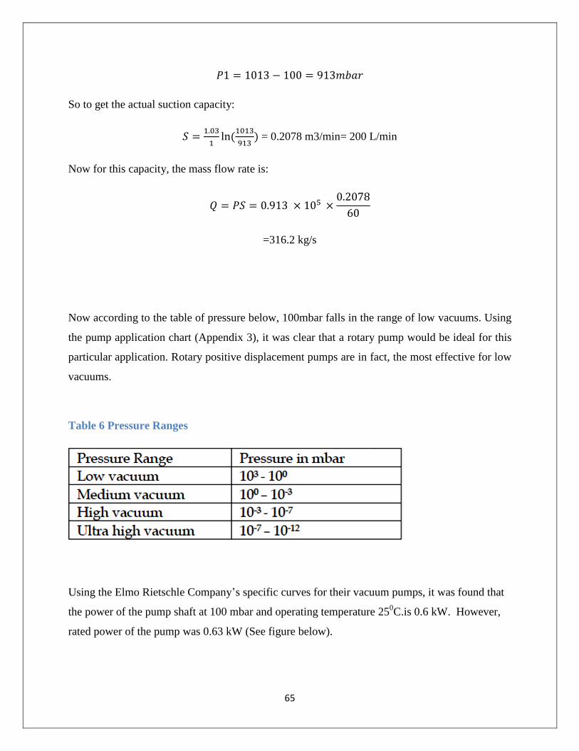
65
So to get the actual suction capacity:
= 0.2078 m3/min= 200 L/min
Now for this capacity, the mass flow rate is:
=316.2 kg/s
Now according to the table of pressure below, 100mbar falls in the range of low vacuums. Using
the pump application chart (Appendix 3), it was clear that a rotary pump would be ideal for this
particular application. Rotary positive displacement pumps are in fact, the most effective for low
vacuums.
Table 6 Pressure Ranges
Using the Elmo Rietschle Company’s specific curves for their vacuum pumps, it was found that
the power of the pump shaft at 100 mbar and operating temperature 250C.is 0.6 kW. However,
rated power of the pump was 0.63 kW (See figure below).

66
(Elmo Rietschle, 2003)

67
8.3 Appendix 3
8.3.1 Mechanical properties of Silica Glass
Thermal Properties Mechanical Properties
Softening Point 1683°C Density 2.20 x 10³Kg/m3
Annealing Point 1215°C Young’s Modulus 74 x 106KN/m2
Strain Point 1120°C Rigidity Modulus 32 x 106KN/m2
Continuous Operating Temp 1000°C Compressive Strength 20 x 106KN/m2
Electrical Information Tensile Strength 70 x 103KN/m2
Electrical Resistivity 2 x 10¹⁹ ohm cm at
20°C Shear Strength 70 x 103KN/m2
2 x 10⁶ ohm cm at 800°C Mohr’s Hardness 6
Dielectric Strength 10KV/mm at 20°C Optical
2.5KV/mm at 500°C Useful Optical Range Synthetic 180 –2000nm
Chemical Information Natural 275- 2000nm
Total Metallic Impurities 10ppm (Typical) Refractive Index nD(589 nm) – 1.458

68
8.3.2 Motor efficiencies
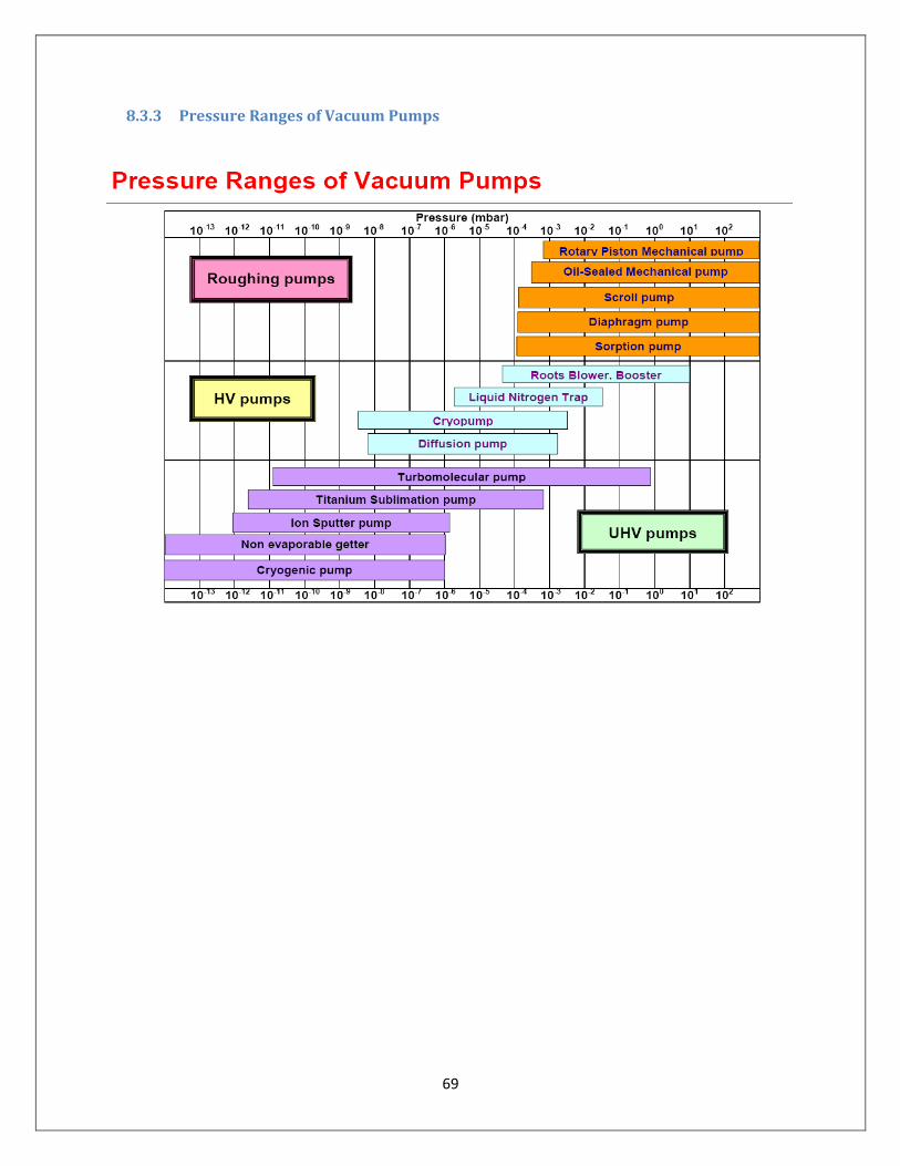
69
8.3.3 Pressure Ranges of Vacuum Pumps

70
The Lamp Recycling process of the Japanese Fluorescent Lamp Company, Ltd.


![[XLS]download.uol.com.brdownload.uol.com.br/fernandorodrigues/a-z-arquivos_da... · Web viewYVAN PEREIRA RANGEL YVES SEGAL YVONE COELHO GOMES YVONE DIAS AVELINO ZïÉLIO SABINO BARBOSA](https://img.pdfslide.net/doc/110x75/5ae74fb37f8b9a3d3b8e5f33/xls-viewyvan-pereira-rangel-yves-segal-yvone-coelho-gomes-yvone-dias-avelino-zlio.jpg)


![Memorias de Um Suicida - Yvone a. Pereira [Espiritismo][Livro Espirita]](https://img.pdfslide.net/doc/110x75/5571fc5549795991699704f8/memorias-de-um-suicida-yvone-a-pereira-espiritismolivro-espirita.jpg)

