Embed Size (px)
Citation preview
UNIVERSITY OF WINDSOR MEMS LAB
An Accurate Model for Pull-in Voltage of Circular Diaphragm Capacitive Micromachined
Ultrasonic Transducers (CMUT)
RCIM SEMINAR NOVEMBER 13, 2009
Mosaddequr Rahman, Sazzadur ChowdhuryDepartment of Electrical and Computer Engineering
University of WindsorWindsor, Ontario, Canada
UNIVERSITY OF WINDSOR MEMS LAB
Research Objective
Develop an accurate Analytical Model to calculate Pull-in Voltageof a CMUT device built with Circular diaphragm.
CMUT devices are a type of MEMS capacitive ultrasonic sensorscharacterized by small device dimensions.
RCIM SEMINAR MEMS Lab NOVEMBER 13, 2009
The model takes into account- Non-linear stretching of the diaphragm due to Large Deflection,- Built-in Residual Stress of the membrane,- Bending Stress, and- the Fringing Field effect, and- the non-linearity of the Electrostatic Field
UNIVERSITY OF WINDSOR MEMS LAB
Presentation Outline
• Motivation
• Basic Device Structure and Operation
• Limitations in Existing Models
RCIM SEMINAR MEMS Lab NOVEMBER 13, 2009
• Limitations in Existing Models
• Solution Approach
• Model Development
• Model Validation
• Conclusions
UNIVERSITY OF WINDSOR MEMS LAB
Motivation
CMUT devices has
Wide Range of Applications- Biomedical Imaging- Automotive Collision Avoidance Radar System- Nondestructive Testing- Microphones
RCIM SEMINAR MEMS Lab NOVEMBER 13, 2009
- Microphones
Superior performance over traditional piezoelectric transducers
-low temperature sensitivity-high signal sensitivity-wide bandwidth -very high level of integration (low cost)
Estimating Pull-in Voltage VPull-in and the Plate Travel Distance xP
before pull-in effect is required for the successful design ofelectrostatic actuators, switches, varactors, and sensors.
UNIVERSITY OF WINDSOR MEMS LAB
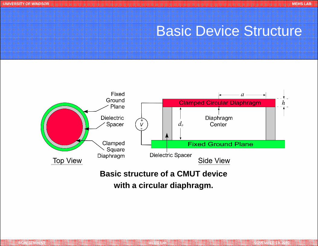
Basic Device Structure
RCIM SEMINAR MEMS Lab NOVEMBER 13, 2009
Basic structure of a CMUT device with a circular diaphragm.
UNIVERSITY OF WINDSOR MEMS LAB
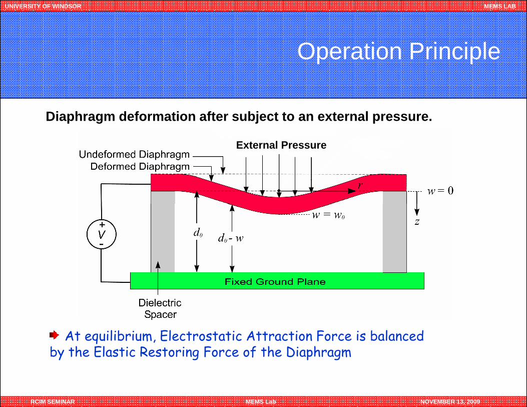
Operation Principle
Diaphragm deformation after subject to an external pressure.
External Pressure
RCIM SEMINAR MEMS Lab NOVEMBER 13, 2009
At equilibrium, Electrostatic Attraction Force is balanced by the Elastic Restoring Force of the Diaphragm
UNIVERSITY OF WINDSOR MEMS LAB
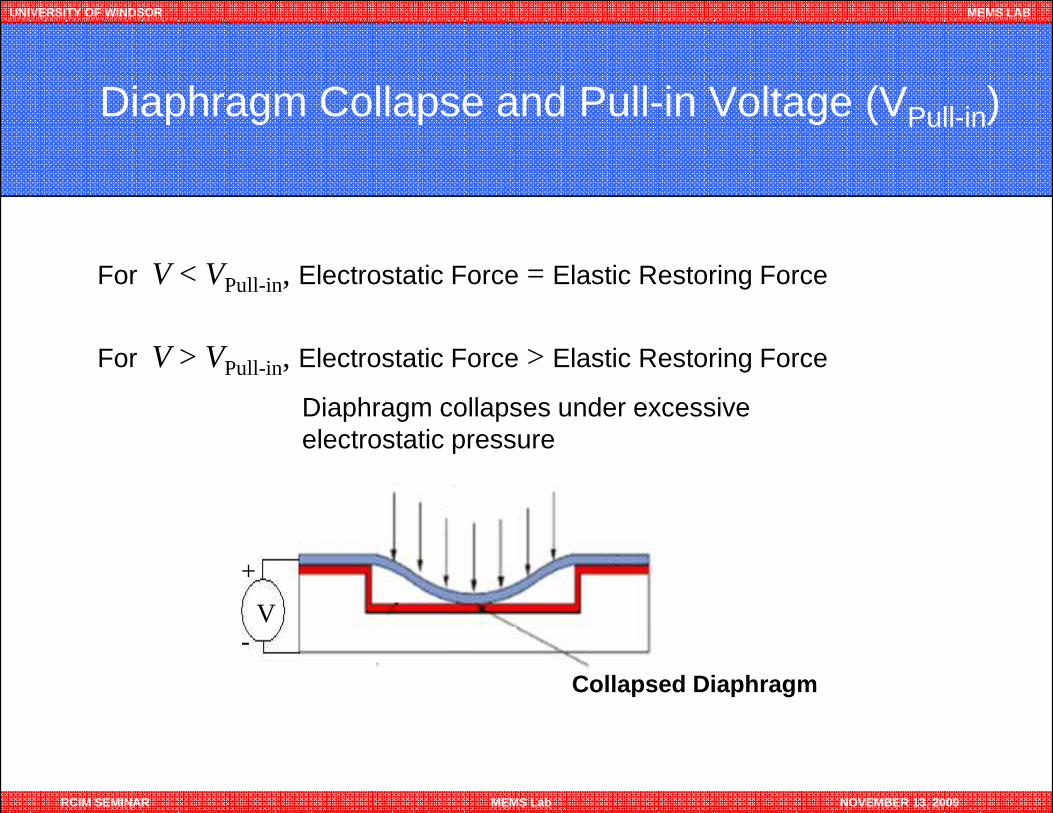
Diaphragm Collapse and Pull-in Voltage (VPull-in)
For V < VPull-in, Electrostatic Force = Elastic Restoring Force
For V > VPull-in, Electrostatic Force > Elastic Restoring Force
Diaphragm collapses under excessive
RCIM SEMINAR MEMS Lab NOVEMBER 13, 2009
Diaphragm collapses under excessive electrostatic pressure
Collapsed Diaphragm
V
+
-
UNIVERSITY OF WINDSOR MEMS LAB
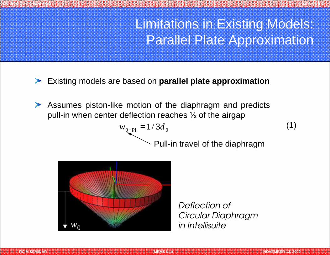
Limitations in Existing Models: Parallel Plate Approximation
Existing models are based on parallel plate approximation
Assumes piston-like motion of the diaphragm and predictspull-in when center deflection reaches ⅓ of the airgap
0PI0 3/1 dw =−(1)
RCIM SEMINAR MEMS Lab NOVEMBER 13, 2009
0PI0 3/1 dw =−
Deflection of Circular Diaphragm in Intellisuitew0
Pull-in travel of the diaphragm
(1)
UNIVERSITY OF WINDSOR MEMS LAB
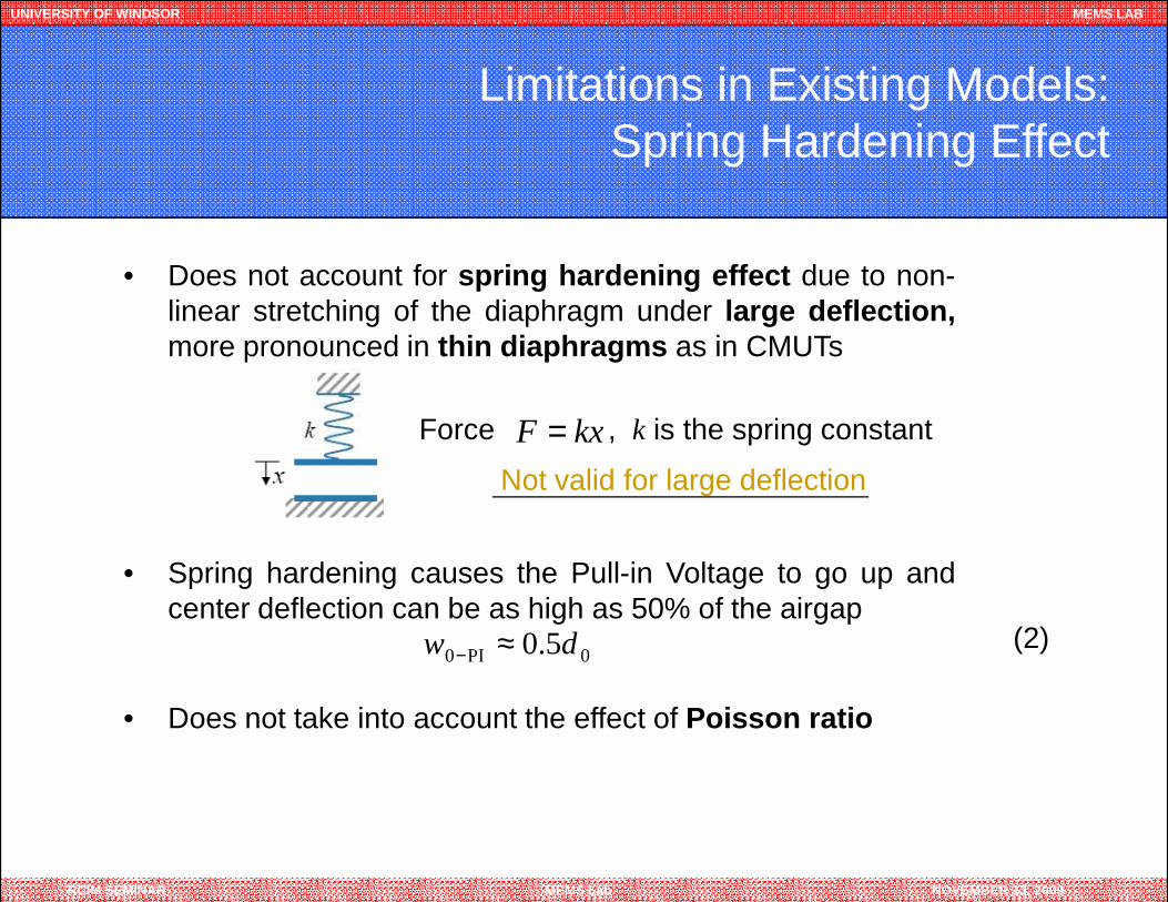
Limitations in Existing Models: Spring Hardening Effect
• Does not account for spring hardening effect due to non-linear stretching of the diaphragm under large deflection,more pronounced in thin diaphragms as in CMUTs
kxF =Force , k is the spring constant
RCIM SEMINAR MEMS Lab NOVEMBER 13, 2009
• Spring hardening causes the Pull-in Voltage to go up andcenter deflection can be as high as 50% of the airgap
• Does not take into account the effect of Poisson ratio
0PI0 5.0 dw ≈−
Not valid for large deflection
(2)
UNIVERSITY OF WINDSOR MEMS LAB
Limitations in Existing Models: Fringing Field Effect
• Existing model does take into account the effect due toFringing Fields
• Fringing Field effect causes spring softening effect of thediaphragm, lowering the pull-in voltage
RCIM SEMINAR MEMS Lab NOVEMBER 13, 2009
diaphragm, lowering the pull-in voltage
• The effect is more pronounced in sensors with smalldiaphragm, such as in CMUT devices
• Above simplifications results in an error as high as 20%when compared to experimental and FEA results
UNIVERSITY OF WINDSOR MEMS LAB
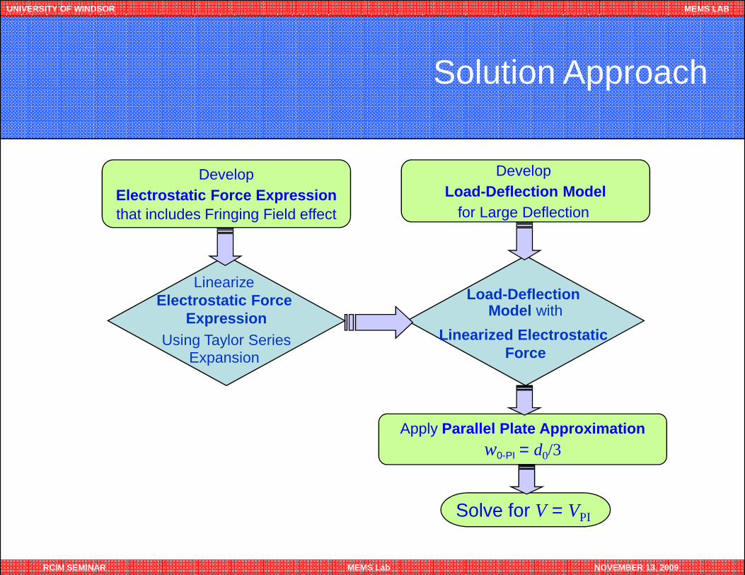
Solution Approach
DevelopElectrostatic Force Expressionthat includes Fringing Field effect
Load-Deflection Linearize
DevelopLoad-Deflection Model
for Large Deflection
RCIM SEMINAR MEMS Lab NOVEMBER 13, 2009
Apply Parallel Plate Approximationw0-PI = d0/3
Solve for V = VPI
Load-Deflection Model with
Linearized Electrostatic Force
LinearizeElectrostatic Force
ExpressionUsing Taylor Series
Expansion
UNIVERSITY OF WINDSOR MEMS LAB
Model Development
RCIM SEMINAR MEMS Lab NOVEMBER 13, 2009
LoadLoadLoadLoad----Deflection ModelDeflection ModelDeflection ModelDeflection Model
UNIVERSITY OF WINDSOR MEMS LAB
Assumptions
As the deflection of membrane is very small compared to its side-length, the forces on the membrane are assumed to always actperpendicular to the diaphragm surface.
The deflection of the membrane is assumed to be a quasistaticprocess, i.e., the dynamic effects due to its motion (such as inertia
RCIM SEMINAR MEMS Lab NOVEMBER 13, 2009
process, i.e., the dynamic effects due to its motion (such as inertiaforce, damping force, etc) are not considered in this analysis.
UNIVERSITY OF WINDSOR MEMS LAB
Load-Deflection Model of a Circular Membrane
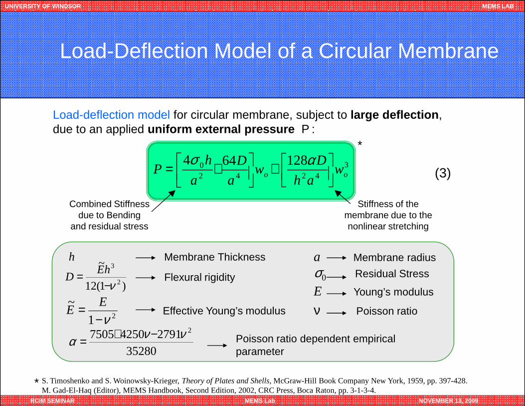
Load-deflection model for circular membrane, subject to large deflection, due to an applied uniform external pressure P :
*
(3)3
42420 128644
oo wah
Dw
a
D
a
hP
+
+= ασ
Stiffness of the Combined Stiffness
RCIM SEMINAR MEMS Lab NOVEMBER 13, 2009
21~
ν−= E
E Effective Young’s modulus
)1(12
~
2
3
ν−= hE
D Flexural rigidity
a Membrane radius
σ0 Residual Stress
E Young’s modulus
ν Poisson ratio
35280279142507505 2ννα −+= Poisson ratio dependent empirical
parameter
Stiffness of the membrane due to the nonlinear stretching
Combined Stiffness due to Bending
and residual stress
h Membrane Thickness
* S. Timoshenko and S. Woinowsky-Krieger, Theory of Plates and Shells, McGraw-Hill Book Company New York, 1959, pp. 397-428.M. Gad-El-Haq (Editor), MEMS Handbook, Second Edition, 2002, CRC Press, Boca Raton, pp. 3-1-3-4.
UNIVERSITY OF WINDSOR MEMS LAB
Model Development
RCIM SEMINAR MEMS Lab NOVEMBER 13, 2009
Electrostatic PressureElectrostatic PressureElectrostatic PressureElectrostatic Pressure
UNIVERSITY OF WINDSOR MEMS LAB
Electrostatic Force Profile
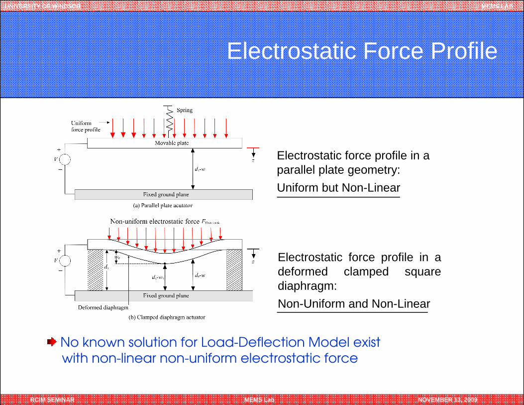
Electrostatic force profile in a parallel plate geometry:
Uniform but Non-Linear
RCIM SEMINAR MEMS Lab NOVEMBER 13, 2009
Electrostatic force profile in adeformed clamped squarediaphragm:
Non-Uniform and Non-Linear
No known solution for Load-Deflection Model exist
with non-linear non-uniform electrostatic force
UNIVERSITY OF WINDSOR MEMS LAB
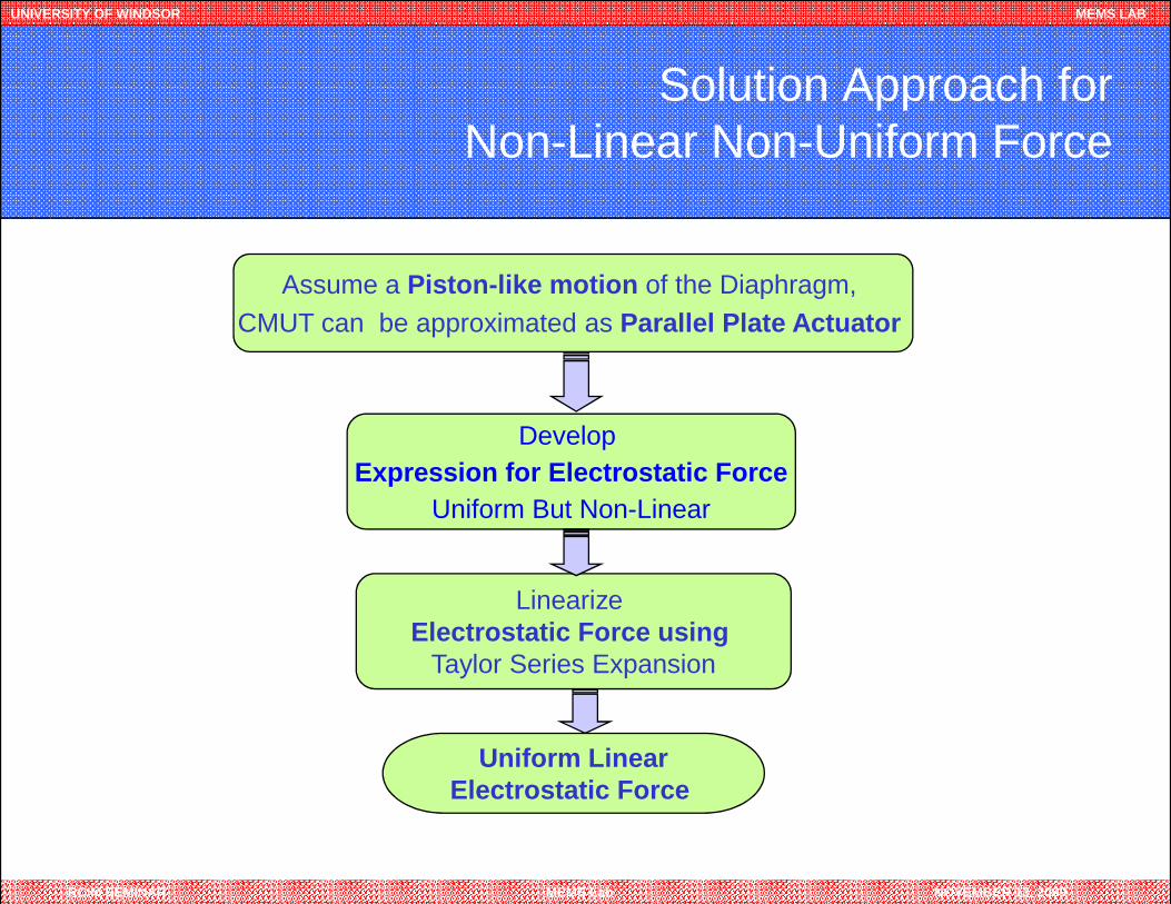
Solution Approach for Non-Linear Non-Uniform Force
Develop
Assume a Piston-like motion of the Diaphragm, CMUT can be approximated as Parallel Plate Actuator
RCIM SEMINAR MEMS Lab NOVEMBER 13, 2009
LinearizeElectrostatic Force using
Taylor Series Expansion
Uniform LinearElectrostatic Force
Expression for Electrostatic ForceUniform But Non-Linear
UNIVERSITY OF WINDSOR MEMS LAB
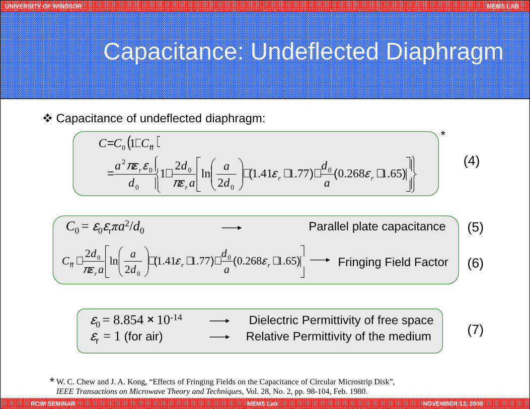
Capacitance: Undeflected Diaphragm
(4)
� Capacitance of undeflected diaphragm:
( )
++++
+=
+=
)()(
ff
65.1268.077.141.12
ln2
1
1
0
0
0
0
02
0
rrr
r
a
d
d
a
a
d
d
a
CCC
εεπε
επε
*
RCIM SEMINAR MEMS Lab NOVEMBER 13, 2009
C0 = ε0εrπa2/d0 Parallel plate capacitance
Fringing Field Factor
++++
≅ )()(ff 65.1268.077.141.1
2ln
2 0
0
0rr
r a
d
d
a
a
dC εε
πε
ε0 = 8.854 ×10⁻¹⁴ Dielectric Permittivity of free spaceεr = 1 (for air) Relative Permittivity of the medium
(5)
(6)
(7)
* W. C. Chew and J. A. Kong, “Effects of Fringing Fields on the Capacitance of Circular Microstrip Disk”, IEEE Transactions on Microwave Theory and Techniques, Vol. 28, No. 2, pp. 98-104, Feb. 1980.
UNIVERSITY OF WINDSOR MEMS LAB
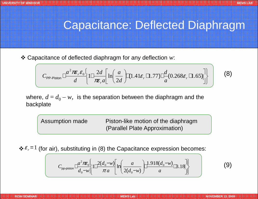
Capacitance: Deflected Diaphragm
where, d = d0 – w, is the separation between the diaphragm and the
� Capacitance of deflected diaphragm for any deflection w:
++++
+≅ )()(-PistonPP 65.1268.077.141.12
ln2
102
rrr
r
a
d
d
a
a
d
d
aC εε
πεεπε (8)
RCIM SEMINAR MEMS Lab NOVEMBER 13, 2009
Assumption made Piston-like motion of the diaphragm(Parallel Plate Approximation)
where, d = d0 – w, is the separation between the diaphragm and the backplate
� (for air), substituting in (8) the Capacitance expression becomes:1 =rε
+−+
−−+
−≅ 18.3
918.1
2
21 0
0
0
0
02
a
wd
wd
a
a
wd
wd
aC
)()(
ln
)(piston-pp π
πε (9)
UNIVERSITY OF WINDSOR MEMS LAB
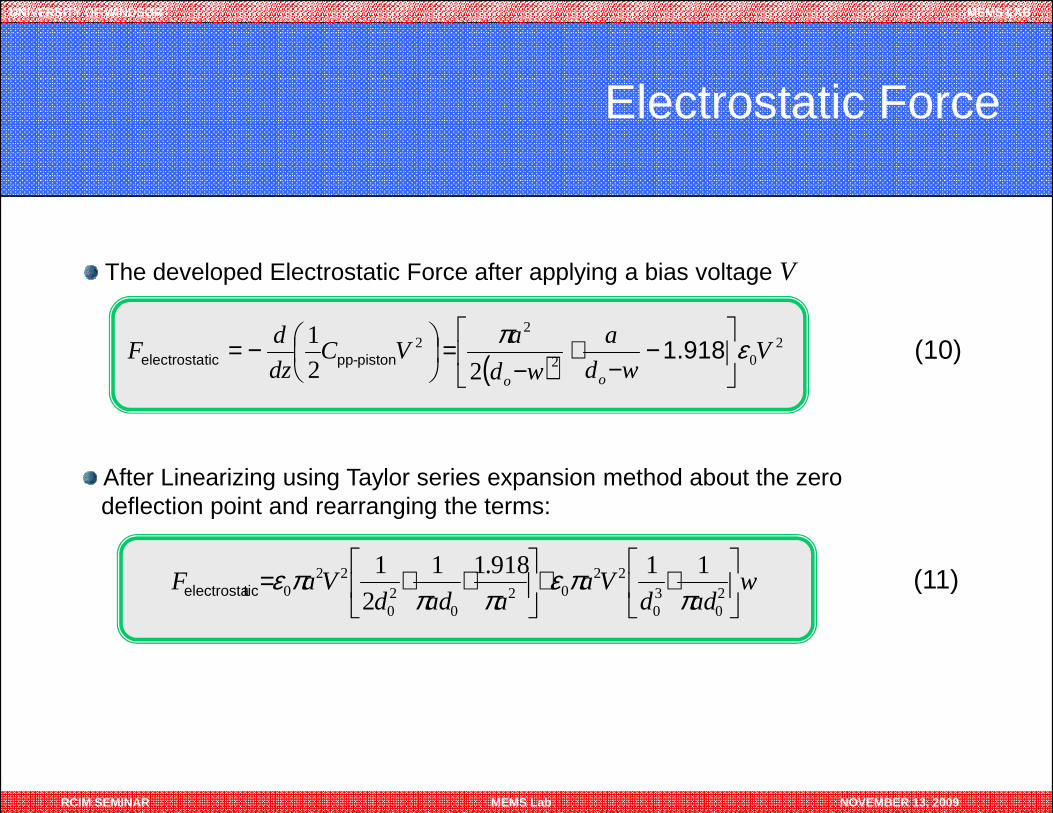
Electrostatic Force
The developed Electrostatic Force after applying a bias voltage V
( )2
02
22
22
1V
wd
a
wd
aVC
dz
dF
oo
επ
−
−+
−=
−= 1.918 piston-ppticelectrosta (10)
RCIM SEMINAR MEMS Lab NOVEMBER 13, 2009
wadd
Vaaadd
VaF
++
++=
20
30
2202
020
220
11918.11
2
1
ππε
πππεticelectrosta
After Linearizing using Taylor series expansion method about the zero deflection point and rearranging the terms:
(11)
UNIVERSITY OF WINDSOR MEMS LAB
Electrostatic Pressure
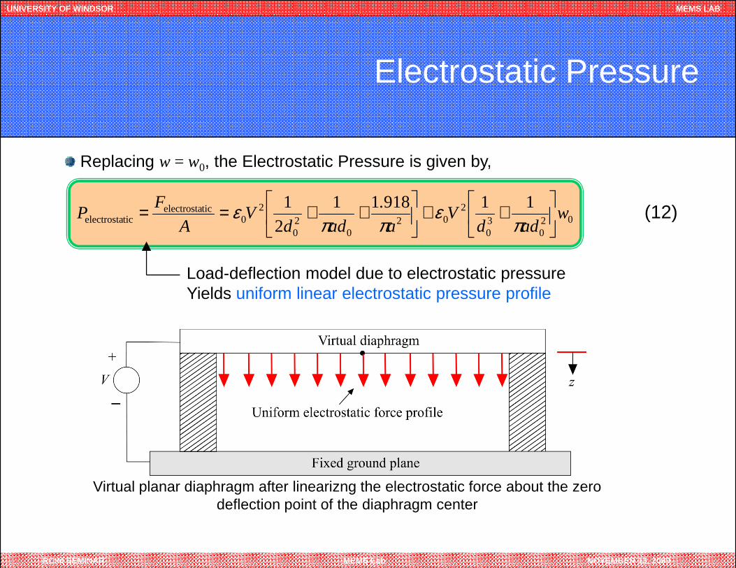
Replacing w = w0, the Electrostatic Pressure is given by,
Load-deflection model due to electrostatic pressureYields uniform linear electrostatic pressure profile
(12)020
30
202
020
20
ticelectrostaticelectrosta
119181121
wadd
Va
.
addV
A
FP
++
++==
πε
ππε
RCIM SEMINAR MEMS Lab NOVEMBER 13, 2009
Yields uniform linear electrostatic pressure profile
Virtual planar diaphragm after linearizng the electrostatic force about the zero deflection point of the diaphragm center
UNIVERSITY OF WINDSOR MEMS LAB
Model Development
RCIM SEMINAR MEMS Lab NOVEMBER 13, 2009
PullPullPullPull----in Voltagein Voltagein Voltagein Voltage
UNIVERSITY OF WINDSOR MEMS LAB
Pressures on Diaphragm at Pull-in Equilibrium
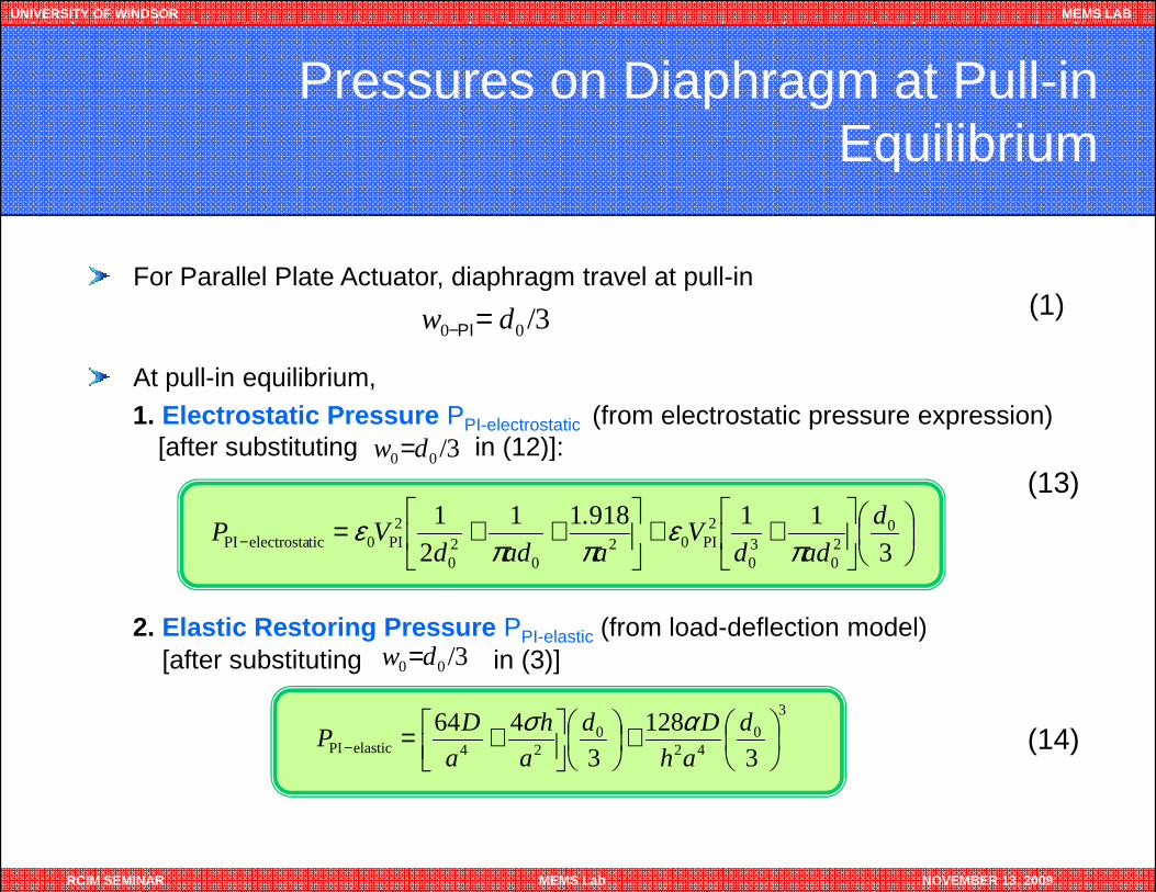
For Parallel Plate Actuator, diaphragm travel at pull-in
At pull-in equilibrium,1. Electrostatic Pressure PPI-electrostatic (from electrostatic pressure expression)
[after substituting in (12)]:
(1)3/00 dw PI=−
3/dw =
RCIM SEMINAR MEMS Lab NOVEMBER 13, 2009
[after substituting in (12)]:
++
++=− 3
119181121 0
20
30
2PI02
020
2PI0ticelectrostaPI
d
addV
a
.
addVP
πε
ππε
3/00 dw =
3/00 dw =
3
042
024elasticPI 3
1283
464
+
+=−d
ah
Dd
a
h
a
DP
ασ
(13)
(14)
2. Elastic Restoring Pressure PPI-elastic (from load-deflection model)[after substituting in (3)]
UNIVERSITY OF WINDSOR MEMS LAB
Pull-in Voltage
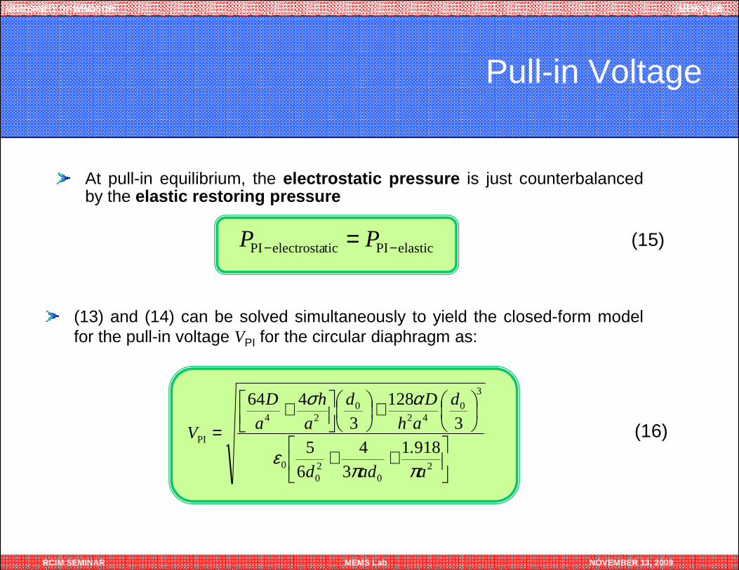
At pull-in equilibrium, the electrostatic pressure is just counterbalancedby the elastic restoring pressure
(15)elasticPIticelectrostaPI −− = PP
RCIM SEMINAR MEMS Lab NOVEMBER 13, 2009
(16)
(13) and (14) can be solved simultaneously to yield the closed-form modelfor the pull-in voltage VPI for the circular diaphragm as:
++
+
+=
20
20
0
3
042
024
PI9181
34
65
3128
3464
a
.
add
d
ah
Dd
a
h
a
D
V
ππε
ασ
UNIVERSITY OF WINDSOR MEMS LAB
RCIM SEMINAR MEMS Lab NOVEMBER 13, 2009
Model ValidationModel ValidationModel ValidationModel Validation
UNIVERSITY OF WINDSOR MEMS LAB
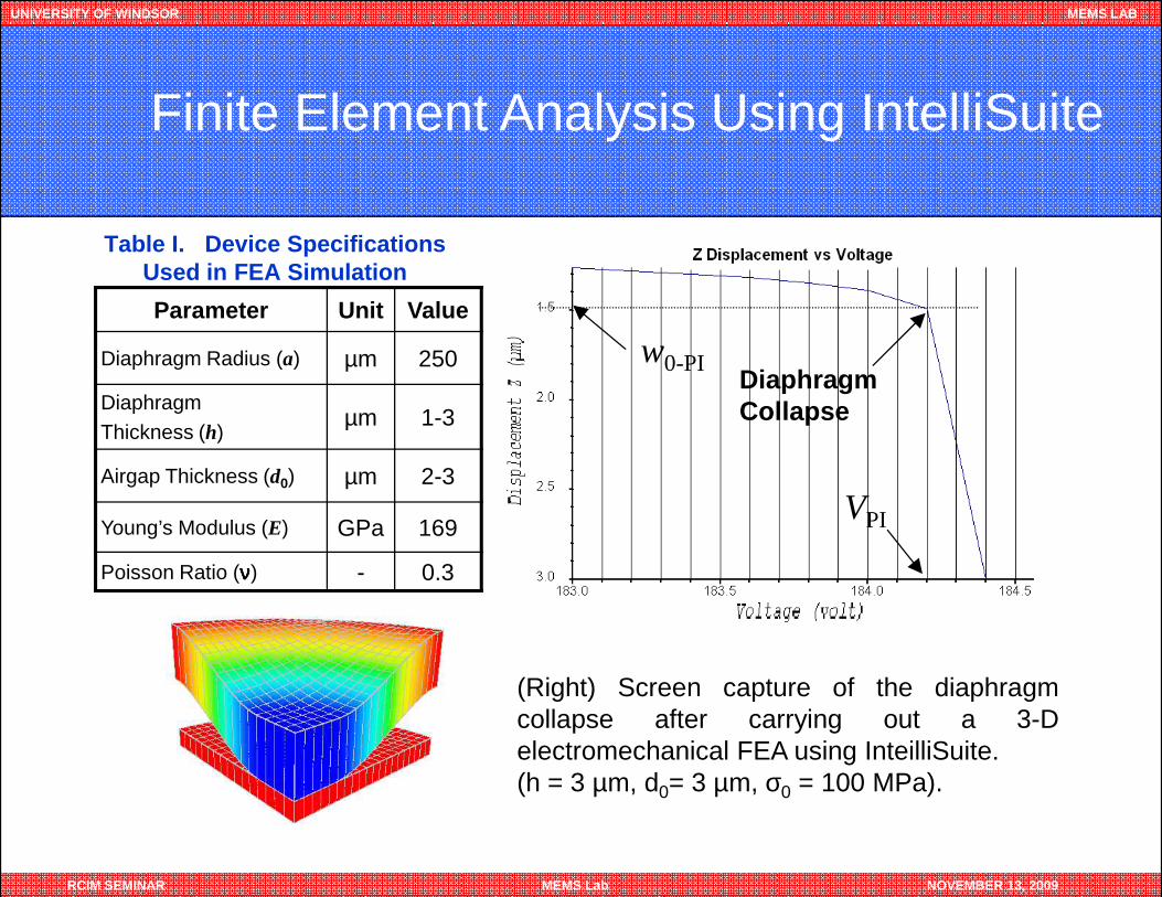
Finite Element Analysis Using IntelliSuite
Parameter Unit Value
Diaphragm Radius (a) µm 250
Diaphragm Thickness (h)
µm 1-3
DiaphragmCollapse
w0-PI
Table I. Device SpecificationsUsed in FEA Simulation
RCIM SEMINAR MEMS Lab NOVEMBER 13, 2009
Airgap Thickness (d0) µm 2-3
Young’s Modulus (E) GPa 169
Poisson Ratio (νννν) - 0.3
(Right) Screen capture of the diaphragmcollapse after carrying out a 3-Delectromechanical FEA using InteilliSuite.(h = 3 µm, d0= 3 µm, σ0 = 100 MPa).
VPI
UNIVERSITY OF WINDSOR MEMS LAB
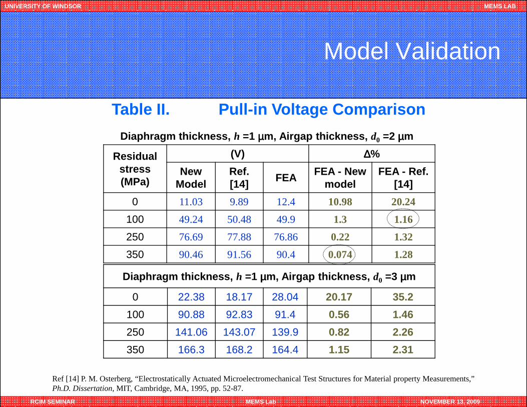
Model Validation
Table II. Pull-in Voltage Comparison
Residual stress (MPa)
(V) ∆∆∆∆%
New Model
Ref. [14]
FEA FEA - New model
FEA - Ref. [14]
0 11.03 9.89 12.4 10.98 20.24
Diaphragm thickness, h =1 µµµµm, Airgap thickness, d0 =2 µµµµm
RCIM SEMINAR MEMS Lab NOVEMBER 13, 2009
0 11.03 9.89 12.4 10.98 20.24
100 49.24 50.48 49.9 1.3 1.16
250 76.69 77.88 76.86 0.22 1.32
350 90.46 91.56 90.4 0.074 1.28
Diaphragm thickness, h =1 µµµµm, Airgap thickness, d0 =3 µµµµm
0 22.38 18.17 28.04 20.17 35.2
100 90.88 92.83 91.4 0.56 1.46
250 141.06 143.07 139.9 0.82 2.26
350 166.3 168.2 164.4 1.15 2.31
Ref [14] P. M. Osterberg, “Electrostatically Actuated Microelectromechanical Test Structures for Material property Measurements,” Ph.D. Dissertation, MIT, Cambridge, MA, 1995, pp. 52-87.
UNIVERSITY OF WINDSOR MEMS LAB
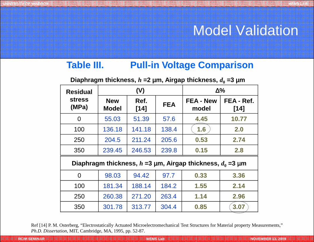
Model Validation
Table III. Pull-in Voltage Comparison
Residual stress (MPa)
(V) ∆∆∆∆%
New Model
Ref. [14]
FEA FEA - New model
FEA - Ref. [14]
0 55.03 51.39 57.6 4.45 10.77
Diaphragm thickness, h =2 µµµµm, Airgap thickness, d0 =3 µµµµm
RCIM SEMINAR MEMS Lab NOVEMBER 13, 2009
0 55.03 51.39 57.6 4.45 10.77
100 136.18 141.18 138.4 1.6 2.0
250 204.5 211.24 205.6 0.53 2.74
350 239.45 246.53 239.8 0.15 2.8
Diaphragm thickness, h =3 µµµµm, Airgap thickness, d0 =3 µµµµm
0 98.03 94.42 97.7 0.33 3.36
100 181.34 188.14 184.2 1.55 2.14
250 260.38 271.20 263.4 1.14 2.96
350 301.78 313.77 304.4 0.85 3.07
Ref [14] P. M. Osterberg, “Electrostatically Actuated Microelectromechanical Test Structures for Material property Measurements,” Ph.D. Dissertation, MIT, Cambridge, MA, 1995, pp. 52-87.
UNIVERSITY OF WINDSOR MEMS LAB
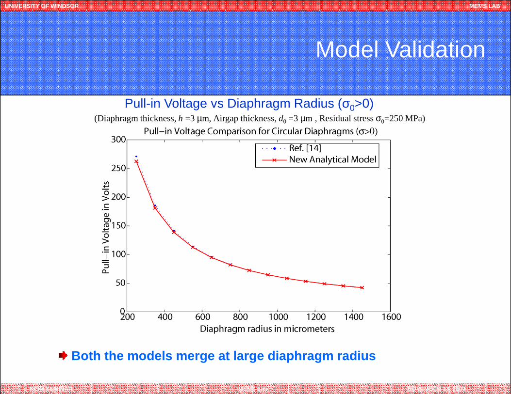
Model Validation
(Diaphragm thickness, h =3 µm, Airgap thickness, d0 =3 µm , Residual stress σ0=250 MPa)
Pull-in Voltage vs Diaphragm Radius (σ0>0)
RCIM SEMINAR MEMS Lab NOVEMBER 13, 2009
Both the models merge at large diaphragm radius
UNIVERSITY OF WINDSOR MEMS LAB
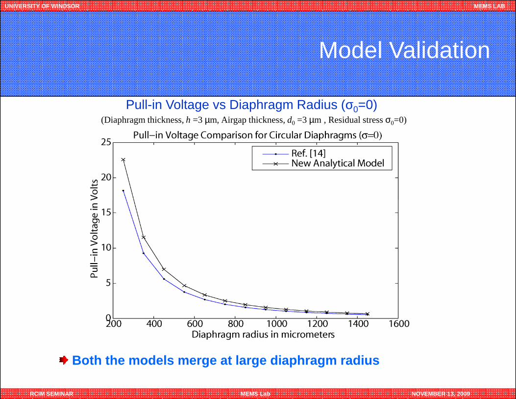
Model Validation
(Diaphragm thickness, h =3 µm, Airgap thickness, d0 =3 µm , Residual stress σ0=0)
Pull-in Voltage vs Diaphragm Radius (σ0=0)
RCIM SEMINAR MEMS Lab NOVEMBER 13, 2009
Both the models merge at large diaphragm radius
UNIVERSITY OF WINDSOR MEMS LAB
Model Limitations
The new analytical method can provide very good approximation ofpull-in voltage for the following limited cases:
� Both the electrodes are required to be parallel prior to anyelectrostatic actuation.
RCIM SEMINAR MEMS Lab NOVEMBER 13, 2009
� The gap between the clamped diaphragm and the backplate shouldbe small enough so that the Taylor series expansion about the zerodeflection point doesn’t introduce any significant error.
� The lateral dimensions of the diaphragm are required to be very largecompared to the diaphragm’s thickness and the airgap.
UNIVERSITY OF WINDSOR MEMS LAB
Conclusions
� A highly accurate closed-form model for the pull-in voltage of a clampedcircular diaphragm CMUT device is presented.
� The model is simple, easy to use and fast, and takes into account both thenon-linear stretching due to large deflection and the non-linearity ofelectrostatic field.
� Excellent agreement with 3-D electromechanical FEA using IntelliSuite with a
RCIM SEMINAR MEMS Lab NOVEMBER 13, 2009
� Excellent agreement with 3-D electromechanical FEA using IntelliSuite with amaximum deviation of 1.6% for diaphragms with residual stress
� Can also be easily extended to a Clamped-edge Square Membrane.
� Besides CMUTs, the Model will also be useful in ensuring safe and efficientoperation of
- MEMS capacitive type pressure sensors- MEMS based microphones- Touch mode pressure sensors- Other application areas where electrostatically actuated
circular diaphragms are used.
UNIVERSITY OF WINDSOR MEMS LAB
Thanks for your Patience
RCIM SEMINAR MEMS Lab NOVEMBER 13, 2009
Thanks for your Patience