Embed Size (px)
Citation preview
Installation and operating manual
Document:M-182.1-UPDL600-ENG
Issue: 06/1999 Rev. : B.1
Upload-DownloadProgram for
NOTIFIER ITALIAa Pittway Company
AM-2000AM-6000
INDEX
INTRODUCTION 1
SOFTWARE INSTALLATION 1
Using the AM6000 UPLOAD-DOWNLOAD program 1
PROGRAM FUNCTIONS 2
PROGRAMMING UPLOAD FROM THE CONTROL PANEL 3
MODIFY PROGRAMMINGS 4
System Parameters 4
Point Rapid Selection 5
Detectors 5
Monitor Modules (MMX) 5
Control Modules (CMX) 6
Zone Programming 6
Group Programming 7
Connection to the AM-6000 control panel - RS 232 Line 8
Connection to the AM-6000 control panel - RS 485 Line 8
Connection to the AM-2000 control panel - RS 485 Line 8
Eng-ndx.VP Installation and operating manual
Doc. M-182.1-UPDL600-ENG Rev. B.1 NOTIFIER ITALIA
INTRODUCTION
The “UPDL-6000” program is an user support for AM-6000 Control Panel programming.
This program is designed to :
• Upload and monitor on a PC all the user-programmed data from the AM-6000 control panel,
• Download on the AM-6000 control panel all the user-programmed data from a specified PC,
• Manage an history log of programmings that the user may edit and transfer on a control panel.
This utility-program allows to perform the same programmings that the operator may carry out directly on the
control panel.
Refer to the “AM-6000 Operating and Programming Manual” for details concerning the programming parame-
ters.
SOFTWARE INSTALLATION
Using the AM-6000 UPLOAD-DOWNLOAD program
» NOTE
Before an upload or download can be performed, the AM-6000 system must include:
• SIB-600 Board with Eprom Revision dated 2-2-1998 or next
• Main Board wit Eprom Revision dated 4-2-1998 or next.
Before an upload or download can be performed, the AM-2000 system must include:
• Eprom Revision dated 28-01-1999 or next
The Upload-Download program must operate with WINDOWS 3.x , WINDOWS 95 / WINDOWS 98 operating
system.
PC Features:
n Windows 3.1 or Windows for Workgroup - CPU 486 - 2 Mbyte Ram - 640 x 480 Black/White Screen.
n Windows 95/98 - CPU 486 - 8 Mbyte Ram - 640 x 480 Black/White or Colour Screen.
The Software includes one 3 ¼ inch. (1.44 Mb)-floppy-disk.
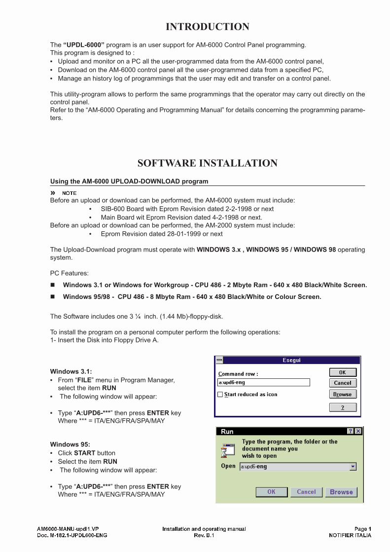
To install the program on a personal computer perform the following operations:
1- Insert the Disk into Floppy Drive A.
Windows 3.1:
• From “FILE” menu in Program Manager,
select the item RUN
• The following window will appear:
• Type “A:UPD6-***” then press ENTER key
Where *** = ITA/ENG/FRA/SPA/MAY
Windows 95:
• Click START button
• Select the item RUN
• The following window will appear:
• Type “A:UPD6-***” then press ENTER key
Where *** = ITA/ENG/FRA/SPA/MAY
AM6000-MANU-updl1.VP Installation and operating manual Page 1
Doc. M-182.1-UPDL600-ENG Rev. B.1 NOTIFIER ITALIA
• If possible, accept the
Directory recommended
for the program installa-
tion.
• To perform the installation
click the UNZIP button.
• To abort the installation
click the “x” button
Once the installation has been performed:
You will get the directory specified during the installation.
To start, run the AM6UPDL.EXE program.
PROGRAM FUNCTIONS
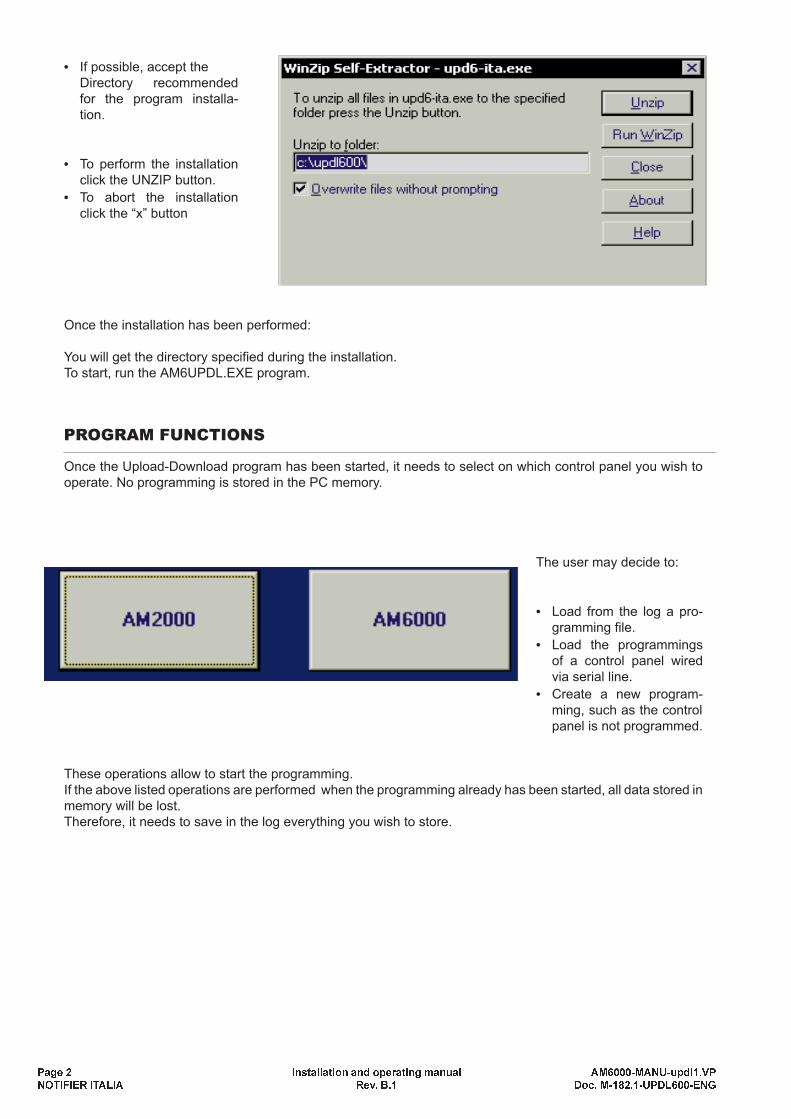
Once the Upload-Download program has been started, it needs to select on which control panel you wish to
operate. No programming is stored in the PC memory.
The user may decide to:
• Load from the log a pro-
gramming file.
• Load the programmings
of a control panel wired
via serial line.
• Create a new program-
ming, such as the control
panel is not programmed.
These operations allow to start the programming.
If the above listed operations are performed when the programming already has been started, all data stored in
memory will be lost.
Therefore, it needs to save in the log everything you wish to store.
Page 2 Installation and operating manual AM6000-MANU-updl1.VP
NOTIFIER ITALIA Rev. B.1 Doc. M-182.1-UPDL600-ENG
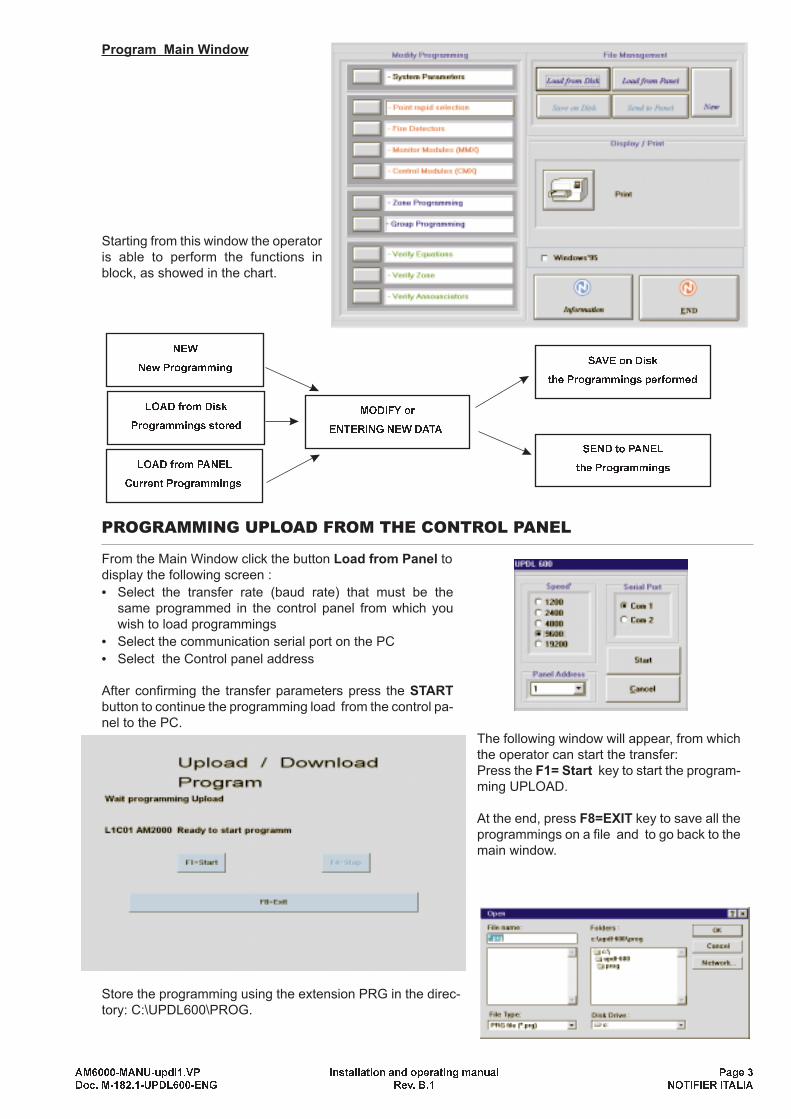
Program Main Window
Starting from this window the operator
is able to perform the functions in
block, as showed in the chart.
PROGRAMMING UPLOAD FROM THE CONTROL PANEL
From the Main Window click the button Load from Panel to
display the following screen :
• Select the transfer rate (baud rate) that must be the
same programmed in the control panel from which you
wish to load programmings
• Select the communication serial port on the PC
• Select the Control panel address
After confirming the transfer parameters press the START
button to continue the programming load from the control pa-
nel to the PC.
The following window will appear, from which
the operator can start the transfer:
Press the F1= Start key to start the program-
ming UPLOAD.
At the end, press F8=EXIT key to save all the
programmings on a file and to go back to the
main window.
Store the programming using the extension PRG in the direc-
tory: C:\UPDL600\PROG.
AM6000-MANU-updl1.VP Installation and operating manual Page 3
Doc. M-182.1-UPDL600-ENG Rev. B.1 NOTIFIER ITALIA
SEND to PANEL
the Programmings
SAVE on Disk
the Programmings performed
MODIFY or
ENTERING NEW DATA
LOAD from Disk
Programmings stored
NEW
New Programming
LOAD from PANEL
Current Programmings
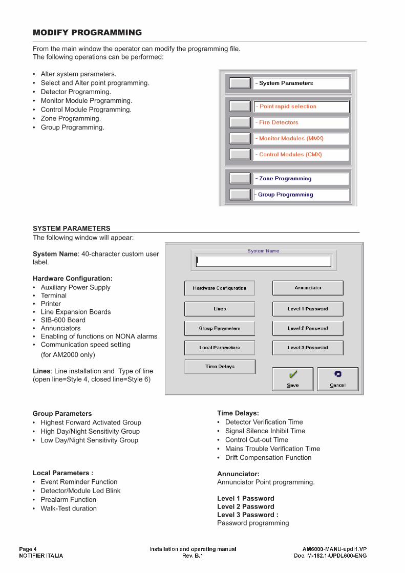
MODIFY PROGRAMMING
From the main window the operator can modify the programming file.
The following operations can be performed:
• Alter system parameters.
• Select and Alter point programming.
• Detector Programming.
• Monitor Module Programming.
• Control Module Programming.
• Zone Programming.
• Group Programming.
SYSTEM PARAMETERS
The following window will appear:
System Name: 40-character custom user
label.
Hardware Configuration:
• Auxiliary Power Supply
• Terminal
• Printer
• Line Expansion Boards
• SIB-600 Board
• Annunciators
• Enabling of functions on NONA alarms
• Communication speed setting
(for AM2000 only)
Lines: Line installation and Type of line
(open line=Style 4, closed line=Style 6)
Page 4 Installation and operating manual AM6000-MANU-updl1.VP
NOTIFIER ITALIA Rev. B.1 Doc. M-182.1-UPDL600-ENG
Group Parameters
• Highest Forward Activated Group
• High Day/Night Sensitivity Group
• Low Day/Night Sensitivity Group
Local Parameters :
• Event Reminder Function
• Detector/Module Led Blink
• Prealarm Function
• Walk-Test duration
Time Delays:
• Detector Verification Time
• Signal Silence Inhibit Time
• Control Cut-out Time
• Mains Trouble Verification Time
• Drift Compensation Function
Annunciator:
Annunciator Point programming.
Level 1 Password
Level 2 Password
Level 3 Password :
Password programming
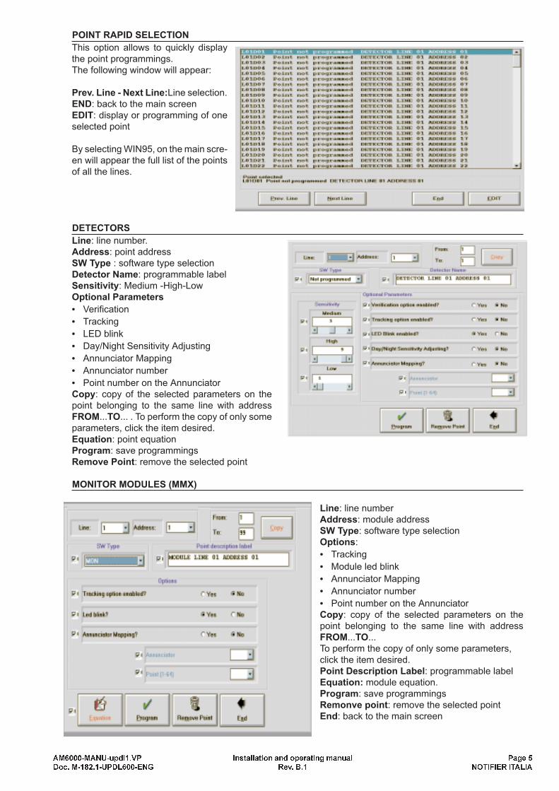
POINT RAPID SELECTION
This option allows to quickly display
the point programmings.
The following window will appear:
Prev. Line - Next Line:Line selection.
END: back to the main screen
EDIT: display or programming of one
selected point
By selecting WIN95, on the main scre-
en will appear the full list of the points
of all the lines.
DETECTORS
Line: line number.
Address: point address
SW Type : software type selection
Detector Name: programmable label
Sensitivity: Medium -High-Low
Optional Parameters
• Verification
• Tracking
• LED blink
• Day/Night Sensitivity Adjusting
• Annunciator Mapping
• Annunciator number
• Point number on the Annunciator
Copy: copy of the selected parameters on the
point belonging to the same line with address
FROM...TO... . To perform the copy of only some
parameters, click the item desired.
Equation: point equation
Program: save programmings
Remove Point: remove the selected point
MONITOR MODULES (MMX)
Line: line number
Address: module address
SW Type: software type selection
Options:
• Tracking
• Module led blink
• Annunciator Mapping
• Annunciator number
• Point number on the Annunciator
Copy: copy of the selected parameters on the
point belonging to the same line with address
FROM...TO...
To perform the copy of only some parameters,
click the item desired.
Point Description Label: programmable label
Equation: module equation.
Program: save programmings
Remonve point: remove the selected point
End: back to the main screen
AM6000-MANU-updl1.VP Installation and operating manual Page 5
Doc. M-182.1-UPDL600-ENG Rev. B.1 NOTIFIER ITALIA
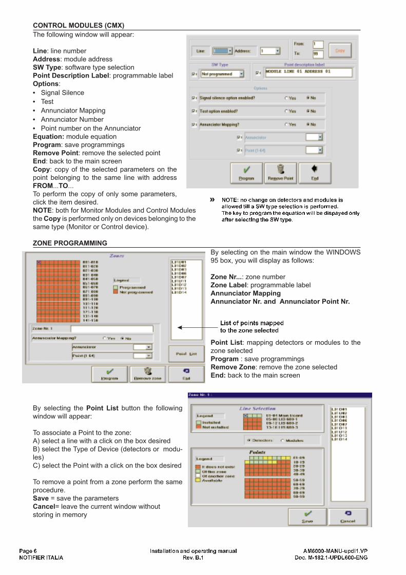
CONTROL MODULES (CMX)
The following window will appear:
Line: line number
Address: module address
SW Type: software type selection
Point Description Label: programmable label
Options:
• Signal Silence
• Test
• Annunciator Mapping
• Annunciator Number
• Point number on the Annunciator
Equation: module equation
Program: save programmings
Remove Point: remove the selected point
End: back to the main screen
Copy: copy of the selected parameters on the
point belonging to the same line with address
FROM...TO...
To perform the copy of only some parameters,
click the item desired.
NOTE: both for Monitor Modules and Control Modules
the Copy is performed only on devices belonging to the
same type (Monitor or Control device).
ZONE PROGRAMMING
By selecting on the main window the WINDOWS
95 box, you will display as follows:
Zone Nr...: zone number
Zone Label: programmable label
Annunciator Mapping
Annunciator Nr. and Annunciator Point Nr.
Point List: mapping detectors or modules to the
zone selected
Program : save programmings
Remove Zone: remove the zone selected
End: back to the main screen
By selecting the Point List button the following
window will appear:
To associate a Point to the zone:
A) select a line with a click on the box desired
B) select the Type of Device (detectors or modu-
les)
C) select the Point with a click on the box desired
To remove a point from a zone perform the same
procedure.
Save = save the parameters
Cancel= leave the current window without
storing in memory
Page 6 Installation and operating manual AM6000-MANU-updl1.VP
NOTIFIER ITALIA Rev. B.1 Doc. M-182.1-UPDL600-ENG
List of points mapped
to the zone selected
» NOTE: no change on detectors and modules is
allowed till a SW type selection is performed.
The key to program the equation will be dispayed only
after selecting the SW type.

On the contrary, not selecting the WINDOWS 95 box, the
following screen will be displayed:
Zone Nr...: zone number
Zone Label: programmable label
Annunciator Mapping
Annunciator Nr. and Annunciator Point Nr.
Point List: mapping detectors or modules to the zone sele-
cted
Program: save programmaings
Remove Zone: remove the zone selected
End: back to the main screen
By selecting the Point List button the following
window will appear:
Line Selection
Point Selection
Add Point= add the selected point in the list
Remove Point= after selecting a point in the list, click
this key to remove the point
Save= save the settings
Cancel = leave the current window without
storing in memory
GROUP PROGRAMMING
The following window will appear:
Group: group number
Group Type: Forward (FGRP) - Reverse (RGRP)
Field non-modifiable. It depends on the program-
ming performed in System Parameters at the item
Group Parameters.
Annunciator Mapping
Annunciator Nr. and Annunciator Point Nr.
Equation: equation mapped to the group
Program : save the programmings
Remove Group: remove the group selected
End: back to the main screen
EQUATION
In any screen, by selecting EQUATION the fol-
lowing window will be displayed:
Device Address= is the device whose equation is
going to be programmed
Equation= equation display
Characters available= characters still at disposal
to write the equation
Operator/Operand Keys=click these buttons to
enter the operator or the operand in the equation
Remove Last = delete the last item entered
Delete CBE= clear the equation
Save= save the eqution
Cancel= leave the current window without storing
in memory
AM6000-MANU-updl1.VP Installation and operating manual Page 7
Doc. M-182.1-UPDL600-ENG Rev. B.1 NOTIFIER ITALIA
List of points mapped
to the zone selected

Connection to the AM-6000 control panel - RS 232 Line
Connection to the AM-6000 control panel - RS 485 Line
Connection to the AM-2000 control panel - RS 485 Line
Page 8 Installation and operating manual AM6000-updl-colleg.VP
NOTIFIER ITALIA Rev. B.1 Doc. M-182.1-UPDL600-ENG
1
25-PIN PC CONNECTOR9-PIN PC CONNECTOR
AM-6000 SIB 600
Wiring cannot exceed 15 metres
Type of cable: 3 x 0,5 mm2shielded Earth connection to the
control panel cabinet
Wiring cannot exceed 1800 metres
Type of cable: 2 x (0,5 mm2each 500 metres) shielded
Twisted and Shielded
9-PIN PC CONNECTOR
25-PIN PC CONNECTOR
AM-6000 SIB 600
IT-485 INTERFACE
SW A B
W1 ON ...
W2 ... ON
RS
485
RS
232
Earth connection to the
control panel cabinetWiring cannot exceed 15 metres
Type of cable: 3 x 0,5 mm2shielded
RX
TX
GND
RX
TX
GND
RX
TX
GND
RX
TX
GND
RTS
25-PIN PC CONNECTOR
RX
TX
GND
RX
TX
MAIN BOARD
Wiring cannot exceed 15 metres
RX
TX
GND
RTS
GND
All rights reserved.
All specifications are subject to change without notice.
Delivery times depend on product availability.
Document:M-182.1-UPDL600-ENG
Issue: 06/1999 Rev. : B.1
NOTIFIER ITALIA S.r.l.
Via Grandi, 22 - 20097 San Donato Milanese (MI)
Tel. : 02/51897.1 (ISDN)
Fax : 02/5189730
http://www.notifier.it