Embed Size (px)
Citation preview

COPY
-1- Jun./03/’10
~Features ~
Important notice about installation of this KitFor the installation of this Kit, a heavy-duty centrifugal clutch (with 32 weights) and heavy-duty oil pump are needed.※ We disclaim all responsibility for consequential and incidental damages or any other losses arising from the use of the Kit, if your bike is not equipped with these additional hardware.
Instruction Manual forS-Stage+D KIT(106 cc/SCUT/Decompression)
C50 - 0200001 ~ - 2100001 ~ C50 - N000002 ~ V488897 -Z000002M ~ Z069126M - 3000001 ~ 8985028AA01 - 1000001 ~
Super cub 50
Item No.: 01―05―5310Little cub C50 -4300001 ~
AA01-3000001 ~
Excluding
※Not installable on PGM-FI models.
・Thank you for purchasing one of our TAKEGAWA products. Please strictly follow the instructions to install and use the kit.・Before installing the kit, please be sure to check the kit contents. If you have any questions about the kit, please contact your local TAKEGAWA dealer.
◎ Please note: Illustrations and photos may vary from the actual hardware.
PAT No. 4203516US PAT. 7627949
About the spark plugBe sure to replace a spark plug with a CR8HSA (NGK) or U24FSR-U(DENSO). In the case of a non-resistive plug, please replace with C8HSA (NGK) orU24FS-U (DENSO). Subsequently, choose and use a right spark plug with the right grade, depending on the carburetor set up.
About quick starting and sudden accelerationPlease note that sudden acceleration and sudden engine braking will put a heavy load on the engine, and that it may result in crank shaft and enginedamages in the worst case.
Read all instructions before starting the installation.
About fuel to useThis S-Stage Kit is so designed to achieve a higher compression ratio than stock engines. Therefore, high-octane gasoline should always be used. If you use regulargasoline, you cannot get the high performance of the Kit. Also the piston will be damaged and may lead to a serious failure of a motorcycle. Before installing thiskit, make sure that no regular gasoline remains in the fuel tank. In case regular gasoline is remaining in the fuel tank, do replace it with high-octane gasoline.
○ The camshaft with decompression will reduce a load on the transmission or kickshaft, and allows the engine to start with a lighter weight kick even though the engine is powered up such as bore-up to 106cc with our S-Stage (SCUT) Kit.
◎ We do not take any responsibility for any accident or damage whatsoever arising from the use of the Kit not in conformity with the instructions in this Instruction Manual.◎ Please drive safely and follow the local traffic law.◎ We shall be held free from any kind of warranty whatsoever of products other than this product if any defect takes place on the other products than this one after the installation and use of this product.◎ We do not have any information or service data on the combination of our products and other manufacturer’s products.◎ Please note that this Kit is designed for exclusive use with the above-mentioned fitting models and frame numbers only and that it cannot be mounted on any other models.◎For installation, please prepare tools and work with reference to the installation procedures. Besides, this instruction manual, as well as a HONDA's genuine parts service manual, is prepared for persons who have acquired basic skills and knowledge. We recommend those who are technically inexperienced or without enough tools to ask a technically-reliable specialist shop for the installation work.◎ Bolts, nuts and dowel pins will be reused. However, be sure not to use the worn-down or severely-damaged ones, which please do replace with new ones.◎If you use a stock carburetor, do not remove the air cleaner box or air cleaner elements. If you change the carburetor, please do the setting to match various conditions like weather and temperatures. Disregarding these instructions will result in engine troubles and serious accidents.◎ In some cases noise coming from the cylinder may sound louder than stock.◎ This Instruction Manual is prepared mainly for the Cub. Therefore, this Instruction manual has some contents not to apply to other vehicles.◎Always use the supreme unleaded high-octane gasoline.◎ We recommend to install and use an oil cooler for riding at a high outdoor air temperature.◎ We highly recommend to upgrade the exhaust system and the carburetor to ensure the potential even though the stock exhaust system and stock carburetor are fine to ride.
・Always start the engine in a well-ventilated place, and do not turn on the engine in an airtight place. (Otherwise, you will suffer from carbon monoxide poisoning.) ・When you notice something abnormal with your motorcycle, stop riding immediately in a safe place to avoid accidents. ・Before doing work, place the motorcycle on level ground to stabilize its position for safety to avoid the motorcycle overturning. ・Check or carry out maintenance of your motorcycle correctly according to the procedures in the instruction manual or service manual. (Improper checking or maintenance could lead to accidents.) ・If you find damaged parts when inspecting or performing maintenance of your motorcycle, do not use these parts, and replace them with new ones. (The continued use of these damaged parts could lead to accidents.) ・As gasoline is highly flammable, never place it close to fire. Make sure that nothing flammable is near the gasoline. Since vaporized accumulation of gasoline is at high risk of explosion, work in a well-ventilated place. (Otherwise it may cause a fire.)
The following show the envisioned possibility of human death or serious injuries to human bodies as a result of disregarding the following warnings.WARNING
・Please drive safely and follow the local traffic law. ・Work only when the engine and exhaust system are cool to avoid burns. ・Prepare appropriate tools and work properly to avoid the breakage of parts or injuries. ・Always use a torque wrench to tighten bolts and nuts securely to the specified torque to avoid these parts getting damaged or loose. ・As some products and frames have sharp edges or protruding portions, please work with your hands protected to avoid injury. ・Before riding, always check such parts as screws for loose. If you find loose ones, screw them securely up to the specified torque to avoid parts coming off. NOTE: Be sure to re-tighten the cylinder head to the specified torque. ・Always use new gaskets and sealings. About the reused parts, please check carefully for wear or damaged and be sure to replace it with new ones if necessary.
The following show the envisioned possibility of injuries to human bodies and property damage as a result of disregarding the following cautions.CAUTION

COPY
-2- Jun./03/’10
1 Torque wrench 11 Plug wrench (in-vehicle tool)2 Plastic hammer 12 Needle nose plier 3 Cutter knife 13 Thickness gauge4 Open end wrench (10-12) 14 Small slotted screwdriver5 Open end wrench (12-14) 15 Extension (Medium size) 6 Open end wrench (14-17) 16 Extension (Small size) 7 Closed wrench (10-12) 17 Socket wrench (14 mm) 8 Closed wrench (12-14) 18 Socket wrench (12 mm) 9 Closed wrench (14-17) 19 Socket wrench (10 mm) 10 Plug wrench handle (in-vehicle tool) 20 Ratchet wrench
No. Part Name Qty Repair Part Item No. In packs of1 Piston 12 Piston ring 1 13012-RAS-T10 13 Piston pin 1 00-01-0091 (with two circlips) 14 Piston pin circlip 2 00-01-0003 65 Cylinder 16 Cylinder head gasket 17 Cylinder gasket 18 Head cover gasket 1 19 Right-side cover gasket 1 110 Left-side cover gasket 1 111 Tappet cap O-ring 2 212 Exhaust pipe gasket 1 00-01-0064 213 Rubber seal 1 00-01-0066 214 Inlet pipe gasket 1 91301-181-T01 115 Camshaft COMP. 1 14100-GDH-T00 116 Valve rocker arm 2 14431-036-T11 117 Stopper plate 1 00-01-0076 1
01-13-7002
◎Please be informed that, mainly because of improvement in performance, design changes, and cost increase, the product specifications and prices are subject to change without prior notice.◎ This manual should be retained for future reference.
Lesson
◇ Tools to use for the installation
◇ Kit includes:
5
1 3 4
01―02―0127
216 1715
01―08―0331
8
910
1211
14
01―13―7002
01―13―0607
6 7
13
01―13―0606
◇ Bolts and nuts will get loose when turned counterclockwise, and tighten when turned clockwise(some exceptions).◇ At the beginning, hand tighten a screw without using a tool. If it stops turning after giving it one or two turns, the screw may be fixed improperly.◇ To loosen a screw means turning a tightened screw three or four times to the counterclockwise, and to remove it means turning it until it comes off.◇To tighten a screw means to screw it up to keep it from getting loose. The numeric value as a guide at which a screw will not break or get loose when tightened is the so-called "torque." If you do not have a torque wrench, please try to tighten a screw as tight as possible to the point where the screw will not break or get loose, though we can not take any responsibility for the breakage. In case you do not use a torque wrench, you need to judge, only by intuition or using experience, the degree of tightening power at which the bolt will break or get loose.◇ Improper use of tools will result in breakage of a top of a bolt or screw.
※ Please order repair parts with the Repair Part Item No. Without the Repair Part Item No., we may not be able to accept your orders. Some parts are only available as a set. In this case, please order them with the set number.

COPY
-3- Jun./03/’10
Par
t nam
es
Sto
pper
pla
te
※1
The
leng
th o
f the
dow
el p
ins
diffe
rs d
epen
ding
on th
e us
e, w
hich
ple
ase
note
.
※2
The
se h
ardw
are
is n
ot in
clud
ed in
the
kit o
r
will
not
be
used
for
the
inst
alla
tion
of th
is k
it.
※3
Be
sure
to c
hang
e to
CR
8HS
A (
NG
K)
or
U24
FS
R-U
(D
EN
SO
).
Cyl
inde
r
Pis
ton
ring
set
Pis
ton
pin
circ
lip
Pis
ton
pin
Pis
ton
Rub
ber
seal
, 16
MM
Cyl
inde
r ga
sket
Dow
el p
in, 8
x12※
1
Gui
de r
olle
r bo
lt
Was
her,
8 M
M
Bol
t, 6
MM
Cam
cha
in g
uide
rol
ler
CO
MP
.
Dow
el p
in, 8
x14※
1
Bol
t, 6
MM
Spa
rk p
lug
※3
Tap
pet a
djus
ting
hole
cap
O-r
ing,
30
MM
Inle
t pip
e ga
sket
Dow
el p
in, 8
x14※
1
Cyl
inde
r he
ad g
aske
t
※2
Cam
sha
ft C
OM
P.
Cam
spr
ocke
t
Left-
side
cyl
inde
r he
ad s
ide
cove
r
Left-
side
cyl
inde
r he
adsi
de c
over
gas
ket
Dow
el b
olt,
5 M
M
Dow
el p
in, 8
x12※
1
O-r
ing,
30
MM
Tap
pet a
djus
ting
hole
cap
Exh
aust
pip
e ga
sket
Cyl
inde
r he
ad c
over
gas
ket
Hex
nut
, 6 M
M
Sea
ling
was
her
A, 6
MM
(Cop
per
plat
ed)
Cap
nut
, 6 M
M
Cyl
inde
r he
ad c
over
Sea
ling
was
her,
6 M
M
Rig
ht-s
ide
cylin
der
head
sid
e co
ver
Rig
ht-s
ide
cylin
der
head
side
cov
er g
aske
t
Val
ve r
ocke
r ar
m
Tap
pet a
djus
ting
scre
w
Tap
pet a
djus
ting
nut
Val
ve r
ocke
r ar
m s
haft
Fla
nge
bolt,
6x2
0
Fla
nge
bolt,
6x1
10
(Cop
per
or a
alu
min
um)
seal
ing
was
her,
6.5
x12
※1
ノ
ック
ピン
は使
用す
る場
所に
より
全長
が違
いま
す。
ご
注意
下さ
い。
※2
The
se h
ardw
are
is n
ot in
clud
ed in
the
kit o
r w
ill n
ot b
e us
ed fo
r th
e in
stal
latio
n of
this
kit.
※3
Be
sure
to c
hang
e to
CR
8HS
A (
NG
K)
or U
24FS
R-U
(DE
NS
O).
※1
Not
e: P
leas
e in
stal
l the
righ
t siz
ed d
owel
pin
s
i
nto
the
right
pla
ce.
※2
The
se h
ardw
are
is n
ot in
clud
ed in
the
kit o
r w
ill n
ot b
e us
ed fo
r th
e in
stal
latio
n of
this
kit.
※3
Be
sure
to u
se C
R8H
SA
(NG
K) o
r U
24FS
R-U
(
DE
NS
O).
COPY
-4- Jun./03/’10
C
B
A
AB
Notch
Stamped “O” mark
Flywheel
Notch
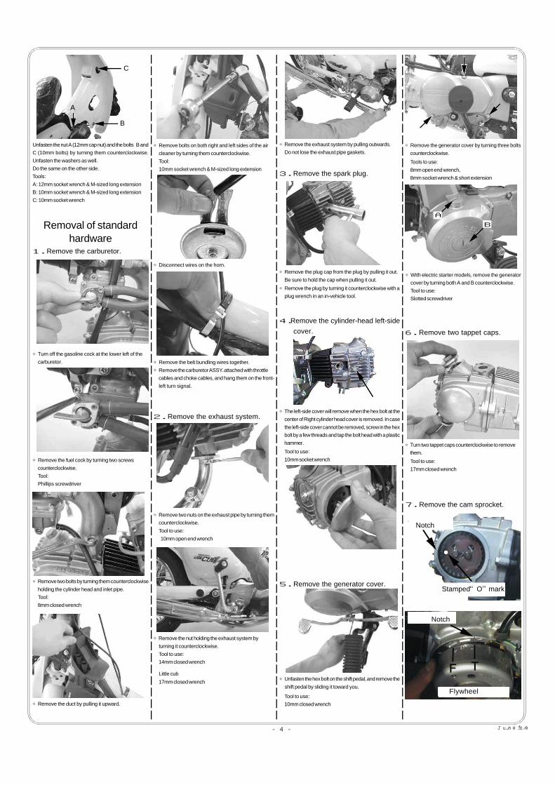
Unfasten the nut A (12mm cap nut) and the bolts B andC (10mm bolts) by turning them counterclockwise.Unfasten the washers as well.Do the same on the other side.Tools:A: 12mm socket wrench & M-sized long extensionB: 10mm socket wrench & M-sized long extensionC: 10mm socket wrench
◇Remove two bolts by turning them counterclockwise holding the cylinder head and inlet pipe. Tool: 8mm closed wrench
◇Remove the duct by pulling it upward.
◇Remove the fuel cock by turning two screws counterclockwise. Tool: Phillips screwdriver
Removal of standardhardware
◇Turn off the gasoline cock at the lower left of the carburetor.
1.Remove the carburetor.
◇Remove bolts on both right and left sides of the air cleaner by turning them counterclockwise. Tool: 10mm socket wrench & M-sized long extension
Little cub
17mm closed wrench
2.Remove the exhaust system.
Tool to use: 10mm open end wrench
◇Remove two nuts on the exhaust pipe by turning them counterclockwise.
3.Remove the spark plug.
4.Remove the cylinder-head left-side cover.
5.Remove the generator cover.
Tool to use: 10mm closed wrench
Tool to use: 10mm socket wrench
6.Remove two tappet caps.
Tool to use: 17mm closed wrench
◇Turn two tappet caps counterclockwise to remove them.
7.Remove the cam sprocket.
Tools to use: 8mm open end wrench, 8mm socket wrench & short extension
◇Disconnect wires on the horn.
◇Remove the belt bundling wires together.◇Remove the carburetor ASSY. attached with throttle cables and choke cables, and hang them on the front- left turn signal.
◇Remove the nut holding the exhaust system by
turning it counterclockwise. Tool to use: 14mm closed wrench
◇Remove the exhaust system by pulling outwards. Do not lose the exhaust pipe gaskets.
◇Remove the plug cap from the plug by pulling it out. Be sure to hold the cap when pulling it out.
◇Remove the plug by turning it counterclockwise with a plug wrench in an in-vehicle tool.
◇The left-side cover will remove when the hex bolt at the center of Right cylinder head cover is removed. In case the left-side cover cannot be removed, screw in the hex bolt by a few threads and tap the bolt head with a plastic hammer.
◇Unfasten the hex bolt on the shift pedal, and remove the shift pedal by sliding it toward you.
◇Remove the generator cover by turning three bolts counterclockwise.
◇With electric starter models, remove the generator cover by turning both A and B counterclockwise. Tool to use: Slotted screwdriver

COPY
-5- Jun./03/’10
Piston pin circlip
Cylinder gasket
Rubber seal
Guide roller bolt
Side bolt
8.Remove the cylinder-head side bolt.
Tool to use: 10mm open end wrench
9.Remove the cylinder head cover.
10.Remove the cylinder head.
11.Remove the cylinder.
◇Remove the loosened guide roller bolt and cylinder side bolt by turning them counterclockwise.
12.Remove the piston.
◇Remove the piston.
13.Remove a cylinder gasket, rubber seal and dowel pin.
14.Installation of clutch and oil pump.
◇Align “T” mark on the flywheel and “O” mark on the cam sprocket with their own notches by turning the flywheel counterclockwise.
With electric starter models
With electric starter models
◇Remove two hex bolts on the cam sprocket by turning them counterclockwise while stop rotating the flywheel. Tools to use: 8mm closed wrench, 14mm socket wrench for stop rotating the flywheel For electric starter models 8mm closed wrench, 14mm socket wrench & M-sized long extension
◇Gently pry the cam sprocket from the camshaft with a small-sized slotted screwdriver to remove it.◇Remove the cam chain from the cam sprocket, and withdraw the cam sprocket.◇Remove the dowel pin fixed in the center of the camshaft.
◇Remove the cylinder-head side bolt holding the cylinder head and cylinder by turning it counterclockwise.
◇Loosen the guide roller bolt on the cylinder and the side bolt between cylinder and crankcase by turning them counterclockwise. Tools to use: 10mm socket wrench
◇Remove four nuts securing the cylinder head cover by turning them counterclockwise in a crisscross pattern.◇Remove four washers beneath the nuts.
Tool to use: 10mm closed or socket wrench
◇Remove the head cover. (If it were hard, tap with a plastic hammer around the perimeter.) If the traces of the gasket material remain on the cylinder head, remove them completely with a scraper or a cutter.
◇Remove the cylinder head from the cylinder by pulling forward. (If it were hard to pull, tap it with a plastic hammer.)◇Remove and keep the two dowel pins to reinstall.
◇Pull out the cylinder. (If it were hard to pull it out, hit the cylinder lightly with a plastic hammer.)
◇While removing the cylinder, the cam chain guide roller will come out.
◇Plug the cylinder hole in the crankcase with a waste cloth to avoid entering any unwanted parts in the case.
◇Remove one of the piston pin circlips with a screwdriver tip. Tool: Small slotted screwdriver
◇To remove the piston pin, please push it forward from the other side with slotted screwdriver.
◇If the gasket does not remove smoothly, please use a scraper or cutter but NOT scratch the crankcase. Keep off any dirt or unwanted parts.
※An oil pump and a heavy-duty clutch are required to install this kit.※Installation of the oil pump and the clutch at this stage is quite easy.

COPY
-6- Jun./03/’10
Exhaustmark
Leftside
Exhaust mark
dowel pin
Top ring
Expander
Siderails
Top ring
Side rails
ExpanderPiston
Pay attention to the cross sectionas well !!
Installation of S-StageKit:
1.Assemble and install a piston.
Tool to use: Small slotted screwdriver
◇You can rather easily install the piston pin circlip by pressing it with a screwdriver, but taking care not to damage the piston with the screwdriver.◇Fix the piston pin circlip first on the left side.
◇Arrange the positions of piston ring-end gapsso they do not align each other.
◇Apply engine oil to the piston-ring grooves, and fix piston rings in the order of an oil ring expander, lower oil ring side rail, upper oil ring side rail, and top ring.
◇Apply engine oil to the piston pin and to a small end of the con’rod, and install the piston pin.
◇Put the oil ring expander.
◇Put the lower oil ring side rail.
◇Put the upper oil ring side rail.
◇Put the top ring.
◇Fix the piston so the arrow on the piston head faces downward, or to the exhaust side.
◇Remove the plugged waste cloth.
◇You can rather easily install the piston pin circlip by pressing it with a screwdriver, but taking care not to damage the piston with the screwdriver. Do the work carefully as, in some cases, the circlip comes off flying while you are pressing it inside. So, wear protective eyeglasses for your eyes.
2.Installation of cylinder.
◇Fix securely the supplied piston pin circlip to the circlip groove.
◇Degrease the mating surfaces of the cylinder and the crankcase to attach the gasket.
◇Install the cylinder gaskets and rubber seal. Remove the excess of the gasket if necessary.
◇Check that two dowel pins are present.
◇Apply engine oil onto the inside of the supplied cylinder and spread the oil evenly with fingers.
◇Fit in the cylinder, by installing the piston rings one by one with fingers, being careful not to move the piston ring-end gaps out of place.
◇Insert the cylinder.
◇Once the piston has been placed inside the cylinder, pass the cam chain through the cylinder, and fix the cylinder into the crankcase.
※Do not align the piston pin clip end-gap with the piston cut out.
Piston
Circlip end-gapPiston cut out
◇Fix a supplied piston pin circlip securely to the grooves for circlip on one side of the piston.
◇To be easier, first, you install one-third of the piston pin into the piston.
◇With pulling the cam chain, fix the guide roller.

COPY
-7- Jun./03/’10
3.Change of camshaft.
◇The arrow should face downward.
Copperwasher
Hex nut
O I L
O I L
M O - O I L
Stopper
M O - O I L
◇Press in the guide roller so the center of the guide roller and the guide-roller bolt hole on the cylinder.
4.Installation of cylinder head.◇Degrease the cylinder head surface and upper surface of the cylinder.
Arrow showing which side shouldface downward.
Tool to use: 10mm closed wrench
◇Attach a head side bolt. Fully tighten the guide roller bolts and the cylinder side bolts which were tightened temporarily.
◇Install the guide roller bolt. (Hand tighten temporarily)
◇Attach the cylinder side bolt. (Hand tighten temporarily)
◇Remove the stock rocker arm shaft and rocker
arm of the cylinder head.
◇Install the cam-sprocket bolt into the camshaft. The camshaft will come out when you pull it out or tap the cylinder head with a plastic hammer. Remove the camshaft while twisting. Do not pull it out by force.
◇Apply engine oil to the rocker arm and adjust bolt included in the kit.
◇Apply engine oil to bearings at the tip on each side of the special cam shaft.
◇Apply molybdenum oil to the cam top.
◇Set the cam shaft on the cylinder head of the kit.
The stopper of the decompression cam is facing up.
◇Attach a stopper plate of the kit and rocker arm to the cylinder head, with a stopper on the stopper plate facing to the right of the cylinder head.
◇Apply molybdenum to the stock rocker arm shaft. And align the holes of stopper plate and rocker arm, and fix the rocker arm shaft.
◇Install the cylinder head while fitting the cam chain.
◇Hold the cam chain with a screwdriver to keep the cam chain from sliding into the cylinder.
◇Attach the cylinder-head cover gasket and head cover.
◇Use the below sets to fit the head cover From the front view: Lower left: copper washer + cap nut Lower right: iron washer + hex nut Two others(upper side): iron washer + cap nut
◇Tighten nuts in a crisscross pattern in two or more steps evenly. Tightening torque:12 N・m (1.2 kgf・m)
Tools to use: 10mm open end wrench 10mm closed wrench

COPY
-8- Jun./03/’10
Notch
Flywheel
Flywheel side
Notch
Flywheel
Cylinder head side
Notch
Stamped“O” mark
Valve clearance(Intake side)
Valve clearance(Exhaust side)
Adjusting screw
Thickness gaugeValve stem
Tightening torque: 10 N・m (1.0 kgf・m) for a guide roller bolt 10 N・m (1.0 kgf・m) for lower and upper side bolts
5.Installation of cam sprocket
◇Align the “T” mark on the flywheel with the notch on the crankcase.
◇Remove the hex bolt next to the change-pedal shaft. As the tensioner will slacken, it will be easy to install the cam chain.
Oil will flow out a little after the boltis tightened. Wipe off the oil.
Change-pedal shaft
Tools to use: 8mm closed wrench 14mm closed wrench
6.Adjustment of tappet clearance.
◇Install two tappet caps.
Tool to use: 17mm closed wrench Tightening torque: 12 N・m (1.2 kgf・m)
7.Installation of cylinder head left-side cover
With electric starter models
With electric starter models
With electric starter models
◇Keep aligning the camsproket bolt hole with the notch of cylinder head and set the shaft with the lift point of camshaft facing to the piston head. This arrangement places the cam shaft at TDC (Top Dead Center) on the compression stroke.
※Installing the optional cam, see its original instruction manual.
◇Set the cam chain so the “O” mark on the cam sprocket and a notch on the cylinder head align together, and install the chain on the cam shaft.
◇Tighten up two cam sprocket bolts while stop rotating the flywheel. Tightening torque: 9 N・m (0.9 kgf・m)
For electric starter models 8mm closed wrench, 14mm socket wrench & M-sized long extension
◇Install the bolt next to the change pedal shaft, and tighten it up. Tightening torque: 10 N・m (1.0 kgf・m) Tools to use: 10mmsocket wrench & M-sized long extension For electric starter models 10mm socket or open end wrench
◇Give the crankshaft more than two turns counterclockwise. First release the decompressing function, and then join together marks on the cam sprocket and on the cylinder head.
※Never rotate the crankshaft clockwise. Otherwise, the decompressor will work,making the valve clearance adjustment impossible.
◇Turn the flywheel until the ”O” mark on the cam sprocket and the “T” mark on the flywheel align with each notch. (Though the flywheel will not stop at the required position because the magnet force repels each other.) It is all right if ”O” and “T” marks align with each notch at the same time after fixing the cam sprocket.
◇After adjusting the tappet, turn the flywheel counterclockwise twice by hand, and then, align “T” and “O” marks each other.
※Never rotate the crankshaft clockwise. Otherwise, the decompressor will work,making the valve clearance adjustment impossible.
◇While tightening a rocker arm’s tappet adjusting screw, tighten the tappet adjusting nut to the extent that a 0.05 mm thickness gauge, placed between the tappet adjusting screw and the valve stem end, can be pulled out with a little resistance. (If you have no idea of the little resistance, use a 0.07 mm and 0.03 mm thickness gauges. When the 0.07 mm gauge won’t go in between the space but the 0.03 mm gauge goes in quite loosely, this means that roughly 0.05 mm clearance is secured.) Set the space at 0.05 mm both for intake and exhaust.
Tools to use: Needle nose plier, 9mm closed wrench, Thickness gauge
For electric starter models, fit together the cranks with a 14mm socket wrench and M-sized long extension.
◇Check to see if the tappet clearance is still right thickness. If not, repeat this adjustment until you get the right tappet clearance.
◇Attach the cylinder-head left-side cover with gasket. When tightening the bolt, make sure that the stoppers of the cover and the cylinder head are mating not to rotate the cover.

COPY
-9- Jun./03/’10
Choke cable
Main harness
AB
C
B
A
A
C
B
3-5-16 Nishikiorihigashi Tondabayashi Osaka JapanTEL : 81-721-25-1357 FAX : 81-721-24-5059 URL : http://www.takegawa.co.jp
Co.,Ltd.
Tool to use: 10mm socket wrench Tightening torque : 12 N・m (1.2 kgf・m)
◇Attach a plug cap to the plug.
◇Install the plug with either an in-vehicle tool or plug wrench.
8.Installation of spark plug.
Tool to use: Plug wrench
Tightening torque: 11 N・m (1.1 kgf・m)
◇Tighten two flange nuts at the exhaust pipe temporarily.
9.Installation of stock exhaust system.
Tool to use: 10mm open end wrench
10.Installation of stock carburetor.
Tightening torque: 10 N・m (1.0 kgf・m)
Tool to use: 8mm closed wrench
◇Turn on the fuel cock.
◇Install three bolts to hold the generator cover. Tools to use: 8mm socket wrench & short extension Tightening torque: 10 N・m (1.0 kgf・m)
11.Installation of generator cover.
(See the stoppers of the cover and cylinder head attaching.)
◇Tighten up the hex nut at the right side of the cylinder head. (The arrow marked nut is the hex nut in the above photo.)
◇Fit the exhaust system between the brake pedal and step, and set the flange under the exhaust port of cylinder head.◇Set the exhaust pipe gasket into the space between the cylinder head and exhaust system. Hand tighten the nut temporarily to fit the exhaust system to the pivot shaft.
◇Tighten the nuts to hold the flange and vehicle. Tightening torque: 10 N・m (1.0 kgf・m) for flange 6 N・m (3.5 kgf・m) for the vehicle Tool to use: 14mm closed wrench Little cub 17mm closed wrench
◇Fully tighten the nuts and bolts at three portions.
◇Make sure the O-ring is installed on the inlet pipe.
◇Bundle the choke cable and main harness.
◇Mount the air cleaner on the frame with one bolt each on right and left sides. Tools to use: 10mm socket wrench & M-sized long extension Tightening torque: 10 N・m (1.0 kgf・m)
◇Install the duct.
◇Fasten two bolts of the intake manifold.
◇Connect wires to the horn.
◇IInstall the fuel cock with two screws. Tool: Phillips screwdriver
◇For an electric starter model, tighten both A and B. Tool to use: Flat tip screwdriver Tightening torque: A 2 N・m (0.2 kgf・m) B 3 N・m (0.3 kgf・m)
◇Install the change pedal. Tool to use: 10mm closed wrench Tightening torque:10 N・m (1.0 kgf・m)◇Make sure that all the nuts and bolts are fastened properly.
12.Installation of leg shield:◇Fit the backside of the leg shield on the frame and then the front side.
At the portion A, tighten the 12mm cap nut, placing theplate in between the nut and leg shield.At the portion B, tighten the 10mm long bolt, placing thespacer between the rear side of the leg shield and thelong bolt.At the portion C, tighten the 10mm bolt, placing thewasher in between the mounting point and the 10mmbolt.Do the same on the other side.Tools to use:A : 12mm socket wrench & M-sized long extensionB : 10mm socket wrench & M-sized long extensionC : 10mm socket wrenchTightening torque: A : 20 N・m (2.0 kgf・m) B,C : 10 N・m (1.0 kgf・m)

COPY
-10- Jun./03/’10
Models Item NosSuper cub 50Little cub12V DAX
02-01-0215 Heavy-duty Centrifugal Clutch Kit02-01-0504 Kit to change centrifugal clutch to the manual clutch
Essential Super Oil Pump
Recommended sprocket for use with S-Stage, SCUT (with a driver weighing 65 kg)
ModelsRear wheel size Clutch Transmission Drive sprocket (Front) Driven sprocket (Rear)
4-speed 16 423-speed 16 354-speed 16 41 (Stock) 3-speed 16 35
Specifications Recommended Sprocket
Centrifugal
Centrifugal
Super cub 50
Little cub
17 inch
14 inch
Models Part No.Super cub 50Little cub
01-16-0051
Models Item NosSuper cub 50 / Little cub 03-05-039
●Before riding:
1 CarburetorHigher power can be attained through the installation of Big Bore Carburetor Kit suitable for each model of a bike for the best performance of S-Stage.
●For best performance:
2 Exhaust systemPlease install various kinds of TAKEGAWA exhaust systems for higher power output.
3 Oil coolerAs a longtime high-load driving will further increase the heat release value of the engine, we recommend you to install an Oil Cooler Kit which keeps oil at appropriate temperaturesand prevents such troubles as oil film shortage at high temperatures.
1 About fuel:◇ Use High-octane gasoline ONLY.◇ If there remains regular gasoline in the fuel tank, always replace it with high-octane gasoline.
2 Additional hardware to be installed: ◇ For driving your bike with this kit installed, the following hardware need to be installed additionally. We disclaim all responsibility for any consequential and incidental damages or any other losses arising from the use of the provided products or parts, if your bike is not equipped with these additional hardware.
2―1 Oil pump:The installation of Super Oil Pump is essential in order to circulate large amounts of oil and to help cool down the engine which the output power and the heat increased.
2―2 Clutch:The stock clutch cannot respond to the high engine power, and, therefore, causes clutch slippage, and consequently cannot transmit the engine power fully to the rear wheel.Therefore, it is necessary to install our heavy-duty clutch such as our Special Clutch.
3 Change of drive sprocket:◇ The installation of this kit will increase the power of your vehicle. So with the stock gearing, you will find it uncomfortable to drive your vehicle because the gear ratio is too low, and will cause severe wears of hardware, not only adversely affecting the engine life, but also possibly breaking the engine in the worst case. Therefore, please replace the drive and driven sprockets to make the gear ratio higher.※ Please note that a driven sprocket is not included in the kit.※ Furthermore, the gear ratio of the sprocket changes according to the clutch type and wheel size. The list below is just for your reference because the configuration in the list below needs to be changed according to the driver’s weight and purpose of use. ※When changing the driven sprocket, remove hardware around the rear wheel. Raise the rear wheel off the ground by placing a racing stand under the engine for working safely.
◇When the stock sprocket is changed to the recommended driven sprocket, the drive chain becomes too long or too short. You need to either shorten the chain by cutting it with a chain cutter, or to prepare a new drive chain.