Embed Size (px)
Citation preview
US Surface Water Treatment Rules (SWTR) for Drinking Water
Spartan Environmental Technologies, LLC
SAFE DRINKING WATER ACT (SDWA) 1974
Authorizes EPA to set national standardsInitially regulated quality at the tap1996 amendment expanded to
source wateroperator trainingfunding for improvementspublic information
SURFACE WATER TREATMENT RULE (SWTR) -1989
Protect against Giardia lamblia, virus, LegionellaInactivate 99.9% of Giardia and 99.99% of VirusMaintain disinfection residualsFiltration required unless avoidance criteria metTurbidity limits of 5 and 0.5 (95%) NTUWatershed control programsWater quality requirements unfiltered systems
STAGE 1 DISINFECTANTS & DISINFECTION BYPRODUCTS RULE (DBPR) - 1998
Interrelate microbial pathogens & DBPM-DBP - microbial/disinfection byproducts rules
Enforce concurrent with IESWTR (next slide)Systems serving 10,000 or more
Surface water - comply by January 2002All other sources - comply by January 2004
Maximum contaminant levels - MCLtotal trihalomethanes, haloacetic acids, bromate & chlorite
Maximum residual disinfectant residuals - MRDLchlorine, chloramines, chlorine dioxide
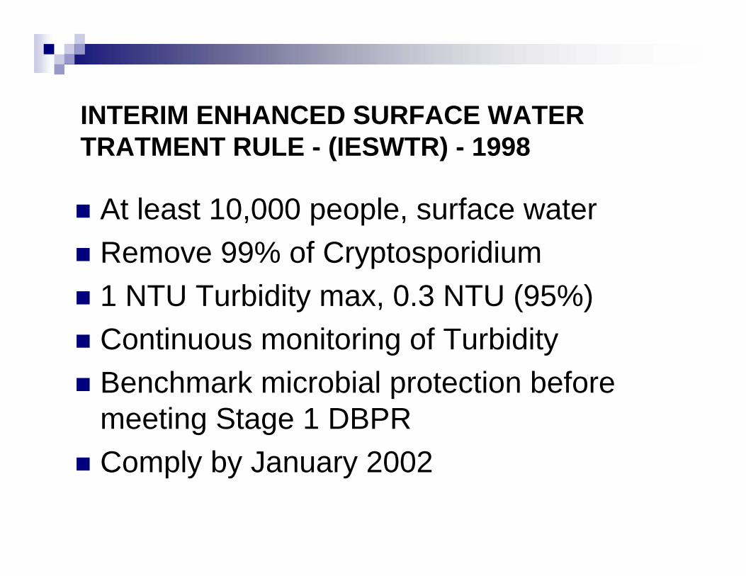
INTERIM ENHANCED SURFACE WATER TRATMENT RULE - (IESWTR) - 1998
At least 10,000 people, surface waterRemove 99% of Cryptosporidium1 NTU Turbidity max, 0.3 NTU (95%)Continuous monitoring of TurbidityBenchmark microbial protection before meeting Stage 1 DBPRComply by January 2002
LONG TERM 1 ENHANCED SURFACE WATER TREATMENT RULE (LT1ESWTR) - 2002
Extended IESWTR to <10,000 peopleEnforcement beginning 2002
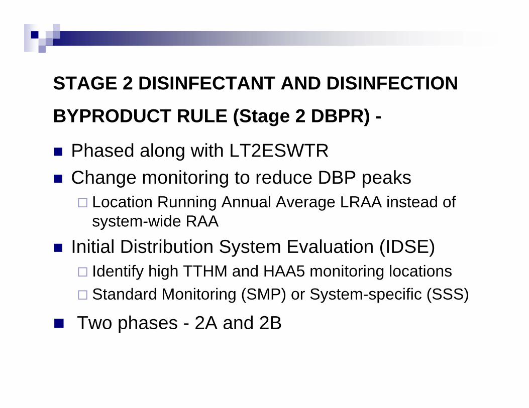
STAGE 2 DISINFECTANT AND DISINFECTION
BYPRODUCT RULE (Stage 2 DBPR) -
Phased along with LT2ESWTRChange monitoring to reduce DBP peaks
Location Running Annual Average LRAA instead of system-wide RAA
Initial Distribution System Evaluation (IDSE)Identify high TTHM and HAA5 monitoring locationsStandard Monitoring (SMP) or System-specific (SSS)
Two phases - 2A and 2B
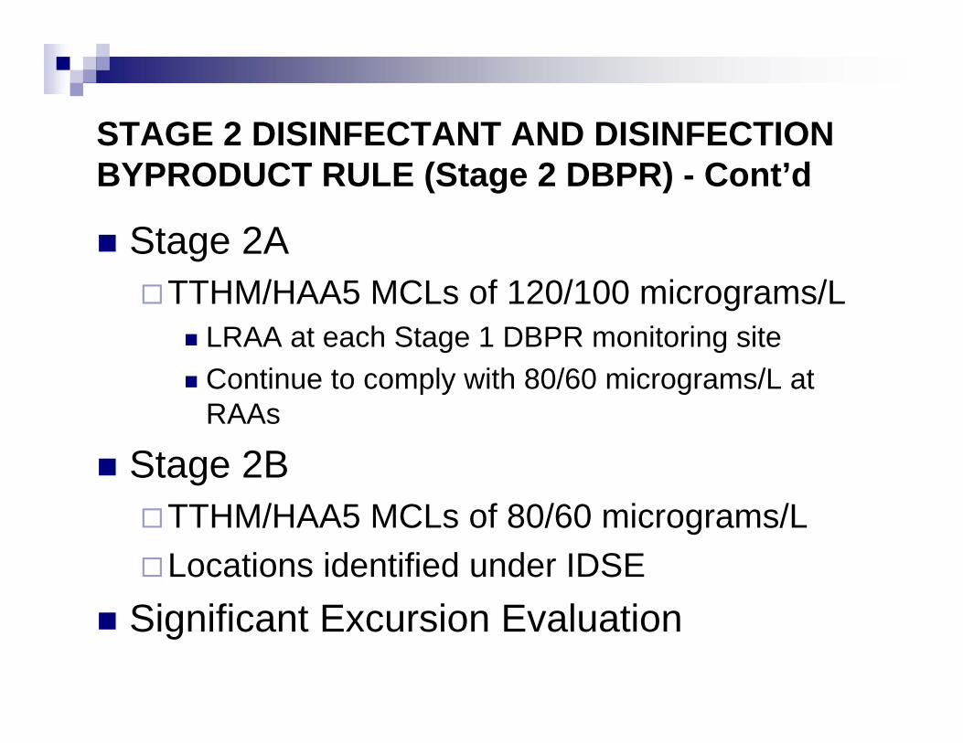
STAGE 2 DISINFECTANT AND DISINFECTION BYPRODUCT RULE (Stage 2 DBPR) - Cont’d
Stage 2ATTHM/HAA5 MCLs of 120/100 micrograms/L
LRAA at each Stage 1 DBPR monitoring siteContinue to comply with 80/60 micrograms/L at RAAs
Stage 2BTTHM/HAA5 MCLs of 80/60 micrograms/LLocations identified under IDSE
Significant Excursion Evaluation
LONG TERM 2 ENHANCED SURFACE WATER TREATMENT RULE (LT2ESWTR) - Proposed Draft 2003
Requirements based on Cryptosporidium (or E-coli) occurrence in source waterSystems classified into four bins that indicate treatment requirementsSelect from a “toolbox” of optionsDetails in “Long Term 2 Enhanced Surface Water Treatment Rule Toolbox Guidance Manual”
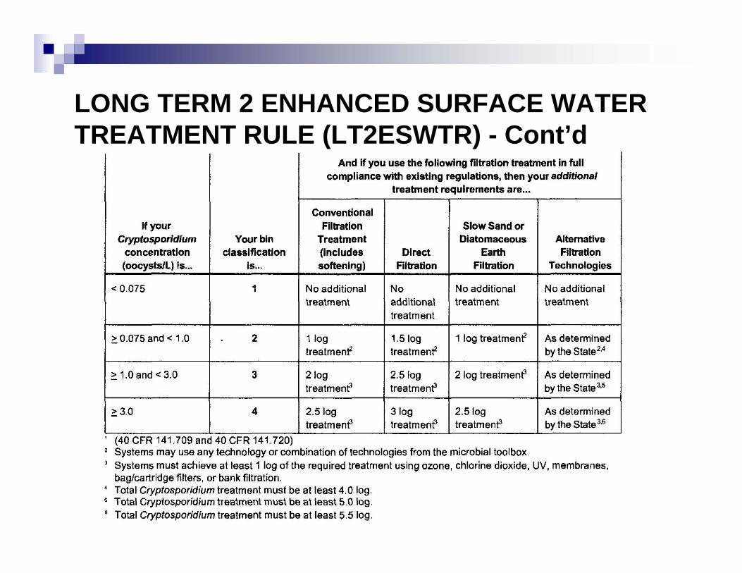
LONG TERM 2 ENHANCED SURFACE WATER TREATMENT RULE (LT2ESWTR) - Cont’d
LONG TERM 2 ENHANCED SURFACE WATER TREATMENT RULE (LT2ESWTR) - Cont’d
SWTR use concentration and time (CT) methods to predict inactivation efficienciesGuidance Manual for Compliance with the Filtration and Disinfection Requirements for Public Water Systems using Surface Water Sources
App. O Guidelines to Evaluate Ozone DisinfectionLong Term 2 Enhanced Surface Water Treatment Rule Toolbox Guidance Manual
App. B Ozone CT Methods
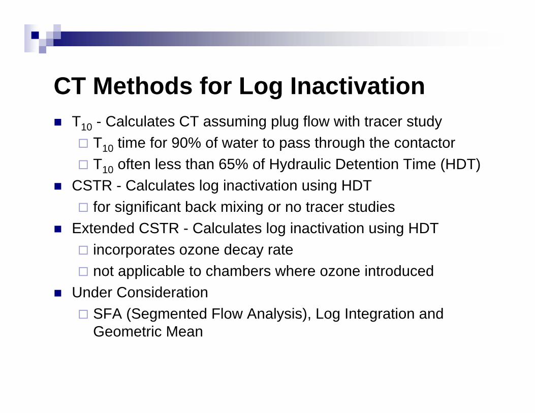
CT Methods for Log InactivationT10 - Calculates CT assuming plug flow with tracer study
T10 time for 90% of water to pass through the contactorT10 often less than 65% of Hydraulic Detention Time (HDT)
CSTR - Calculates log inactivation using HDTfor significant back mixing or no tracer studies
Extended CSTR - Calculates log inactivation using HDTincorporates ozone decay ratenot applicable to chambers where ozone introduced
Under ConsiderationSFA (Segmented Flow Analysis), Log Integration and Geometric Mean
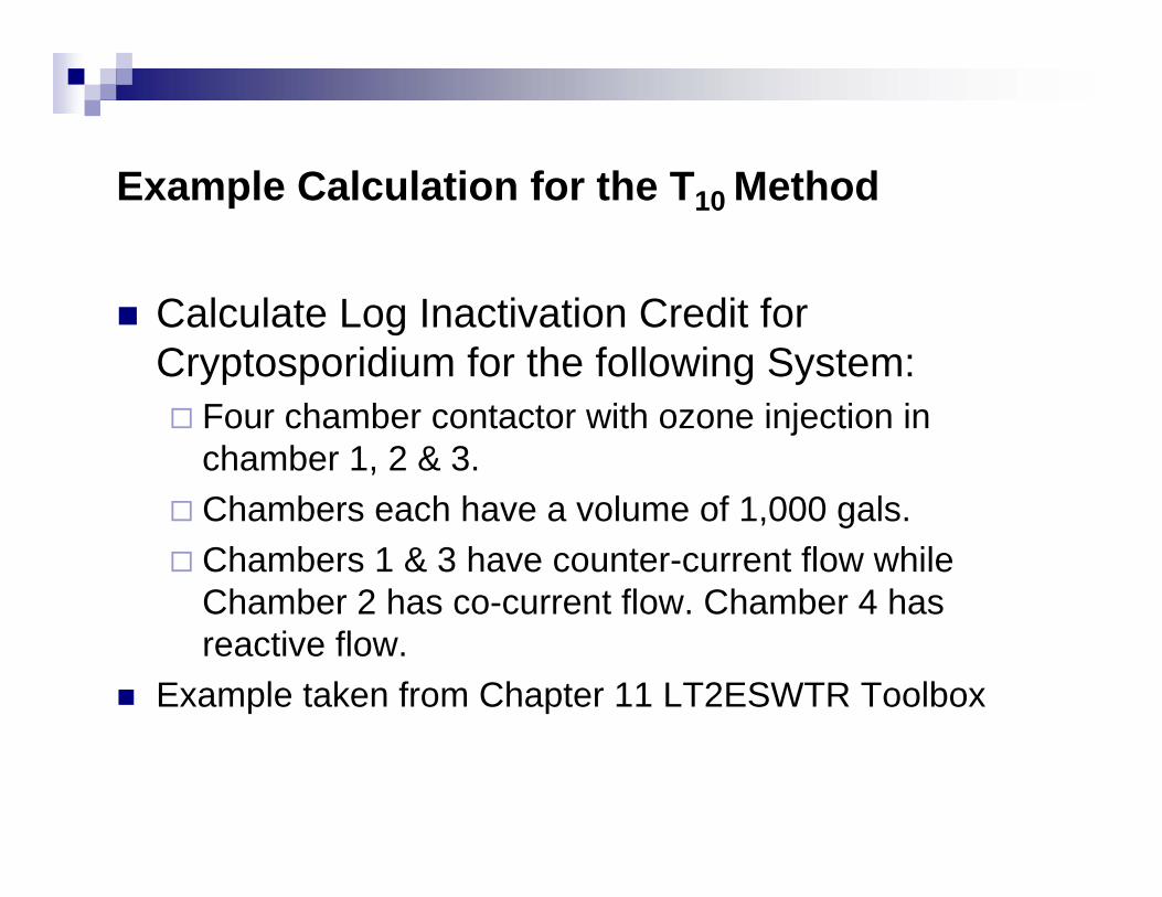
Example Calculation for the T10 Method
Calculate Log Inactivation Credit for Cryptosporidium for the following System:
Four chamber contactor with ozone injection in chamber 1, 2 & 3. Chambers each have a volume of 1,000 gals.Chambers 1 & 3 have counter-current flow while Chamber 2 has co-current flow. Chamber 4 has reactive flow.
Example taken from Chapter 11 LT2ESWTR Toolbox
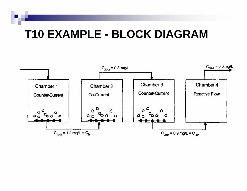
T10 EXAMPLE - BLOCK DIAGRAM
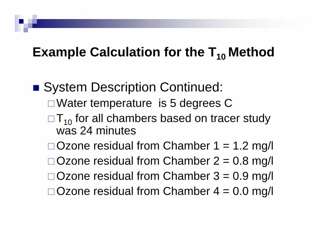
Example Calculation for the T10 Method
System Description Continued:Water temperature is 5 degrees CT10 for all chambers based on tracer study was 24 minutesOzone residual from Chamber 1 = 1.2 mg/lOzone residual from Chamber 2 = 0.8 mg/lOzone residual from Chamber 3 = 0.9 mg/lOzone residual from Chamber 4 = 0.0 mg/l
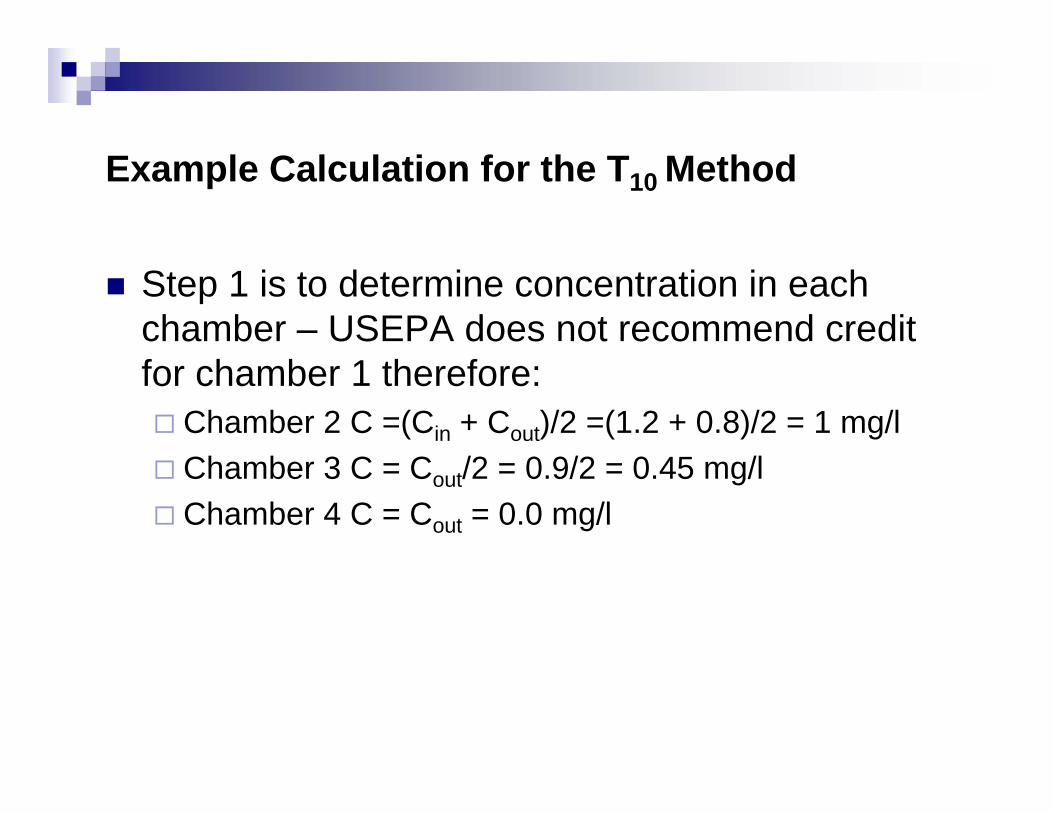
Example Calculation for the T10 Method
Step 1 is to determine concentration in each chamber – USEPA does not recommend credit for chamber 1 therefore:
Chamber 2 C =(Cin + Cout)/2 =(1.2 + 0.8)/2 = 1 mg/lChamber 3 C = Cout/2 = 0.9/2 = 0.45 mg/lChamber 4 C = Cout = 0.0 mg/l
Example Calculation for the T10 Method
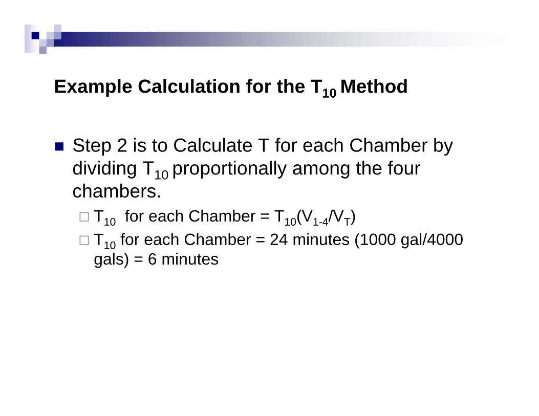
Step 2 is to Calculate T for each Chamber by dividing T10 proportionally among the four chambers.
T10 for each Chamber = T10(V1-4/VT)T10 for each Chamber = 24 minutes (1000 gal/4000 gals) = 6 minutes
Example Calculation for the T10 Method
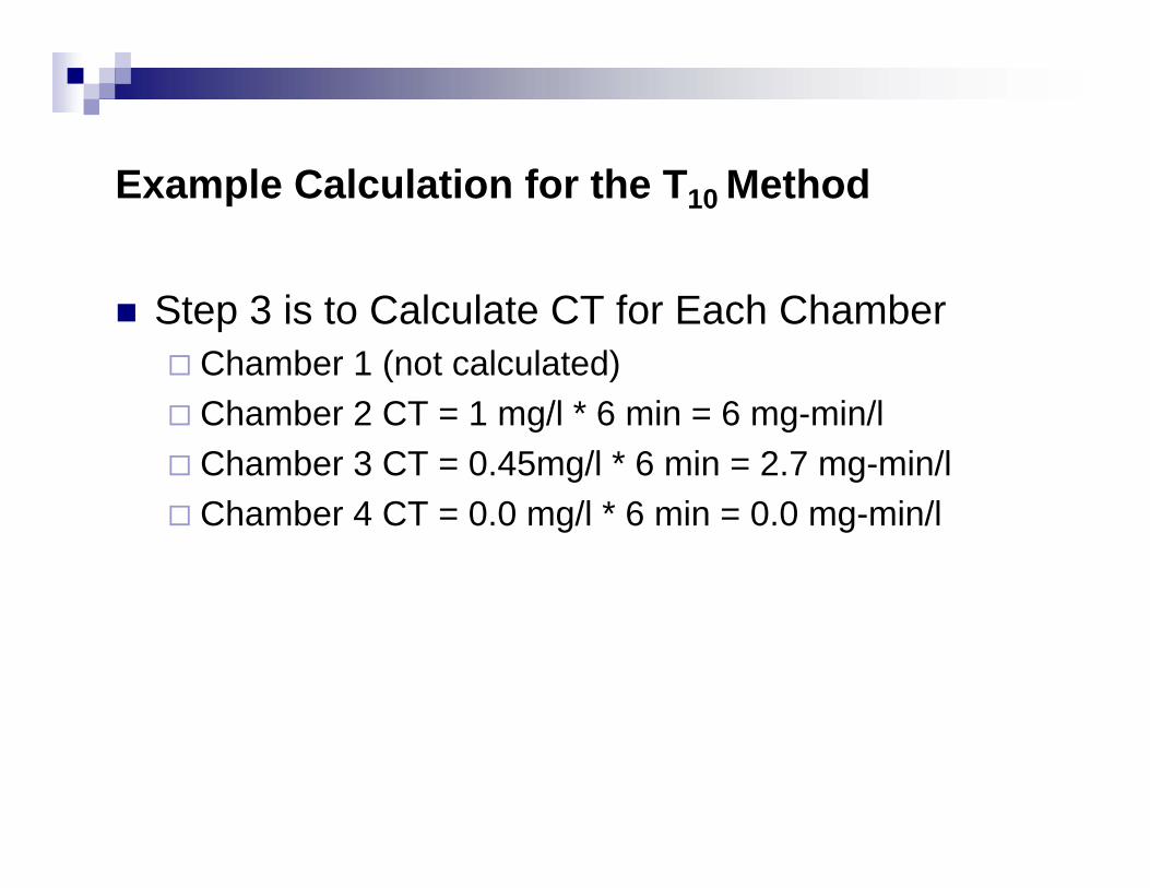
Step 3 is to Calculate CT for Each ChamberChamber 1 (not calculated)Chamber 2 CT = 1 mg/l * 6 min = 6 mg-min/lChamber 3 CT = 0.45mg/l * 6 min = 2.7 mg-min/lChamber 4 CT = 0.0 mg/l * 6 min = 0.0 mg-min/l
Example Calculation for the T10 Method
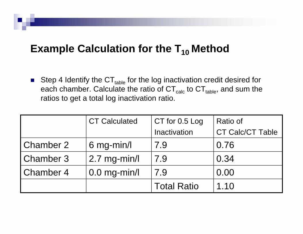
Step 4 Identify the CTtable for the log inactivation credit desired for each chamber. Calculate the ratio of CTcalc to CTtable, and sum the ratios to get a total log inactivation ratio.
1.10Total Ratio0.007.90.0 mg-min/lChamber 40.347.92.7 mg-min/lChamber 30.767.96 mg-min/lChamber 2
Ratio of CT Calc/CT Table
CT for 0.5 LogInactivation
CT Calculated
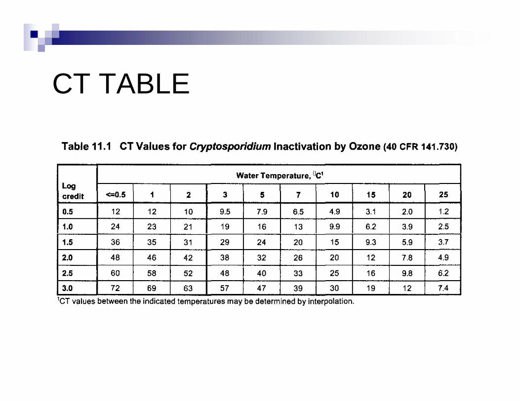
CT TABLE
Example Calculation for the T10 Method
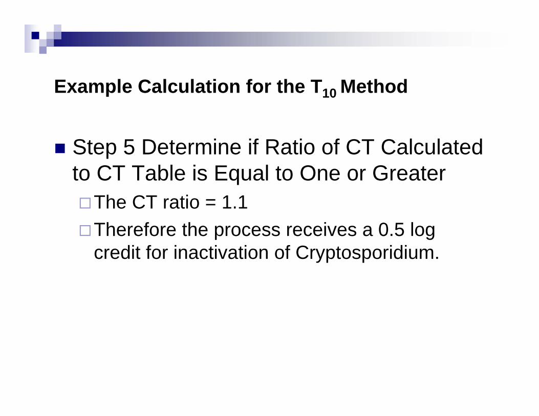
Step 5 Determine if Ratio of CT Calculated to CT Table is Equal to One or Greater
The CT ratio = 1.1Therefore the process receives a 0.5 log credit for inactivation of Cryptosporidium.
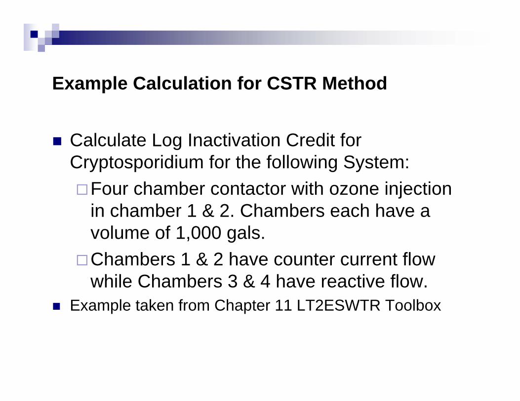
Example Calculation for CSTR Method
Calculate Log Inactivation Credit for Cryptosporidium for the following System:
Four chamber contactor with ozone injection in chamber 1 & 2. Chambers each have a volume of 1,000 gals.Chambers 1 & 2 have counter current flow while Chambers 3 & 4 have reactive flow.
Example taken from Chapter 11 LT2ESWTR Toolbox
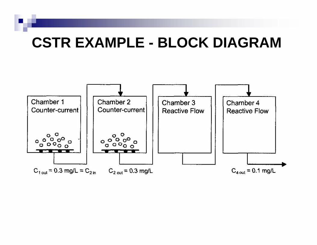
CSTR EXAMPLE - BLOCK DIAGRAM
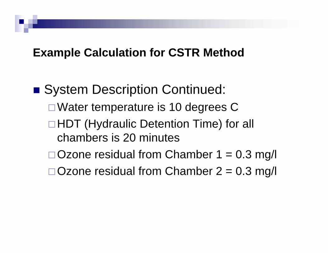
Example Calculation for CSTR Method
System Description Continued:Water temperature is 10 degrees CHDT (Hydraulic Detention Time) for all chambers is 20 minutesOzone residual from Chamber 1 = 0.3 mg/lOzone residual from Chamber 2 = 0.3 mg/l
Example Calculation for CSTR Method
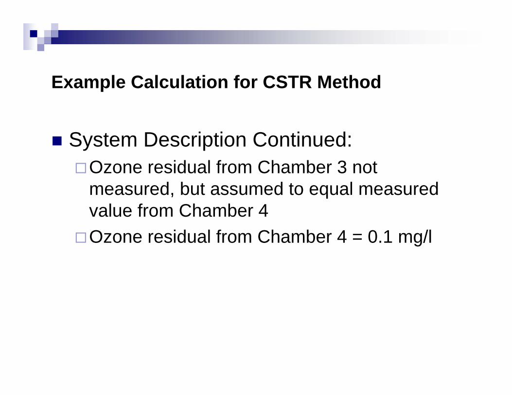
System Description Continued:Ozone residual from Chamber 3 not measured, but assumed to equal measured value from Chamber 4Ozone residual from Chamber 4 = 0.1 mg/l
Example Calculation for CSTR Method
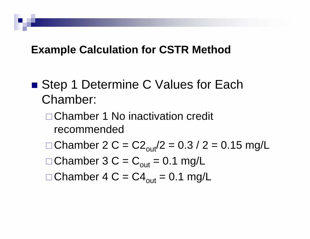
Step 1 Determine C Values for Each Chamber:
Chamber 1 No inactivation credit recommendedChamber 2 C = C2out/2 = 0.3 / 2 = 0.15 mg/LChamber 3 C = Cout = 0.1 mg/LChamber 4 C = C4out = 0.1 mg/L
Example Calculation for CSTR Method
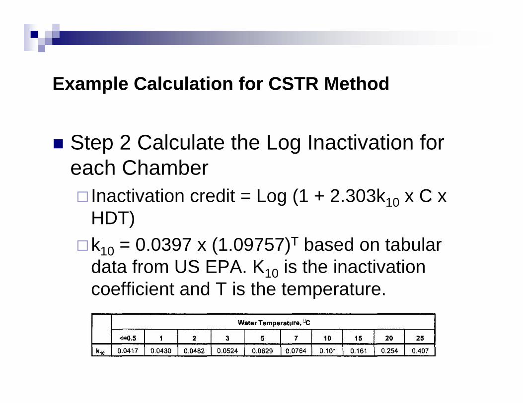
Step 2 Calculate the Log Inactivation for each Chamber
Inactivation credit = Log (1 + 2.303k10 x C x HDT)k10 = 0.0397 x (1.09757)T based on tabular data from US EPA. K10 is the inactivation coefficient and T is the temperature.
Example Calculation for CSTR Method
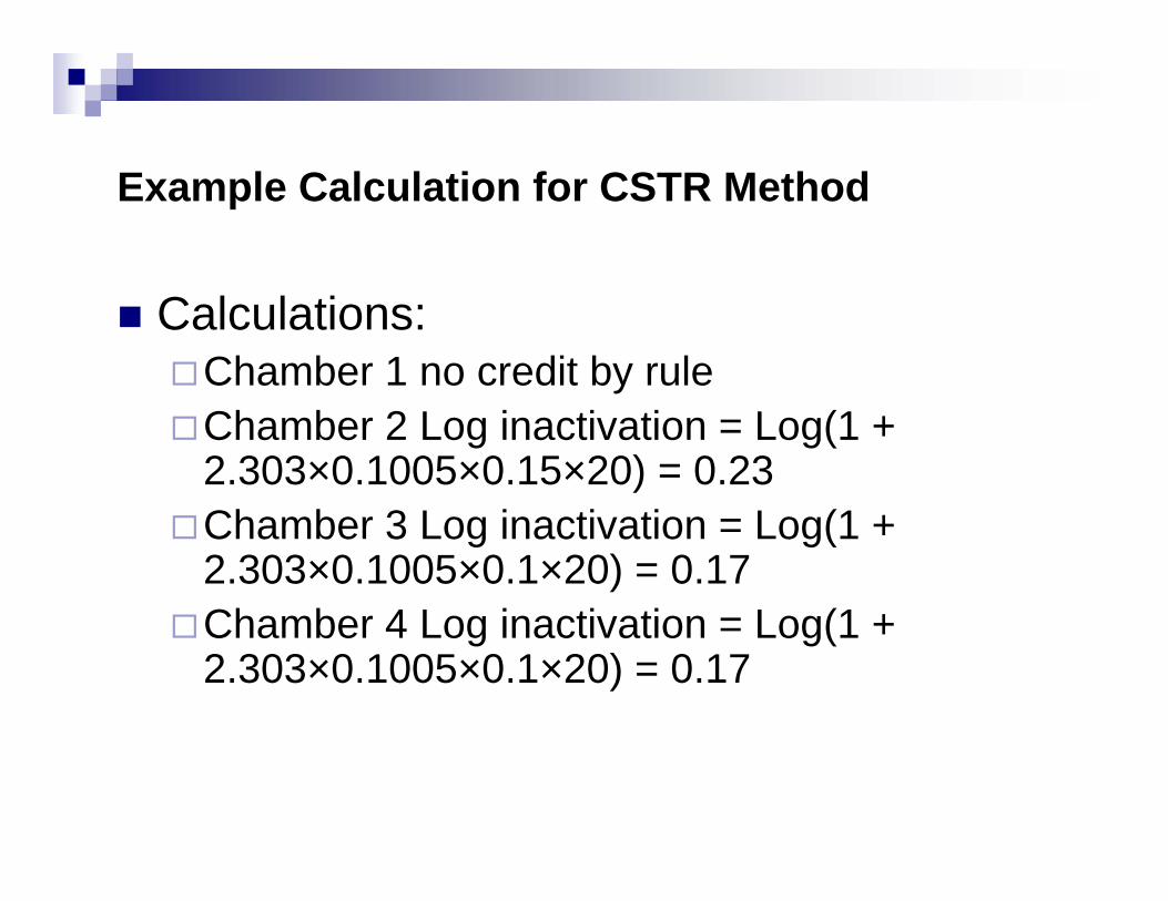
Calculations:Chamber 1 no credit by ruleChamber 2 Log inactivation = Log(1 + 2.303×0.1005×0.15×20) = 0.23Chamber 3 Log inactivation = Log(1 + 2.303×0.1005×0.1×20) = 0.17Chamber 4 Log inactivation = Log(1 + 2.303×0.1005×0.1×20) = 0.17
Example Calculation for CSTR Method
Step 3 Sum the log inactivations to determine the log credit achieved:
The total log-inactivation across the contactor is 0.23 + 0.17 + 0.17 = 0.57 log inactivation, therefore 0.5 log credit achieved.
Example Calculation for Extended CSTR Method
Description of System:12 chamber over and under contactorEach Chamber is 104,000 galsTotal flow is 50 MGDWater Temperature is 20 degrees COzone added only to chamber 1Residual measurements at outlet of chambers 2, 5 & 8
Example taken from Appendix B LT2ESWTR Toolbox
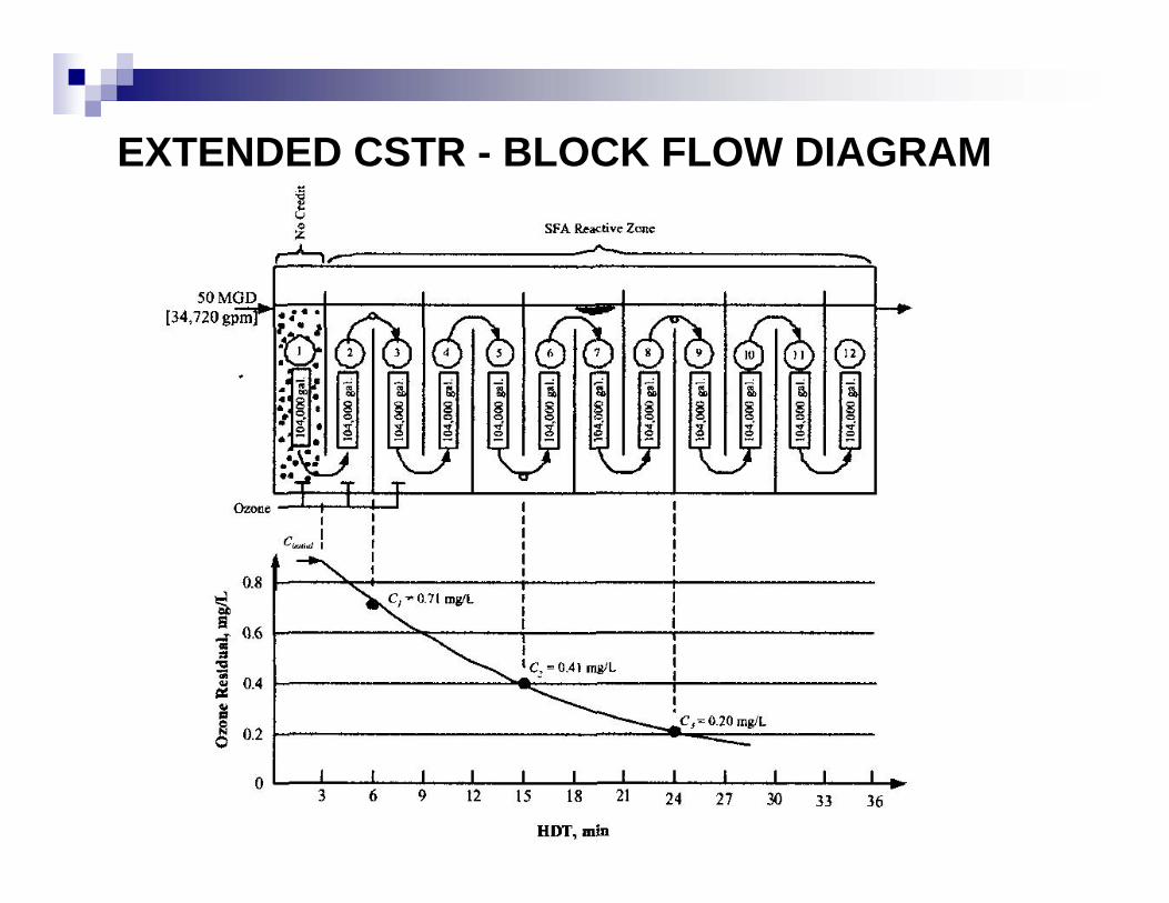
EXTENDED CSTR - BLOCK FLOW DIAGRAM
Example Calculation for Extended CSTR Method
MethodsNo Credit is given cryptosporidium inactivation in chamber 1Chambers 2-12 evaluated using Extended CSTR model
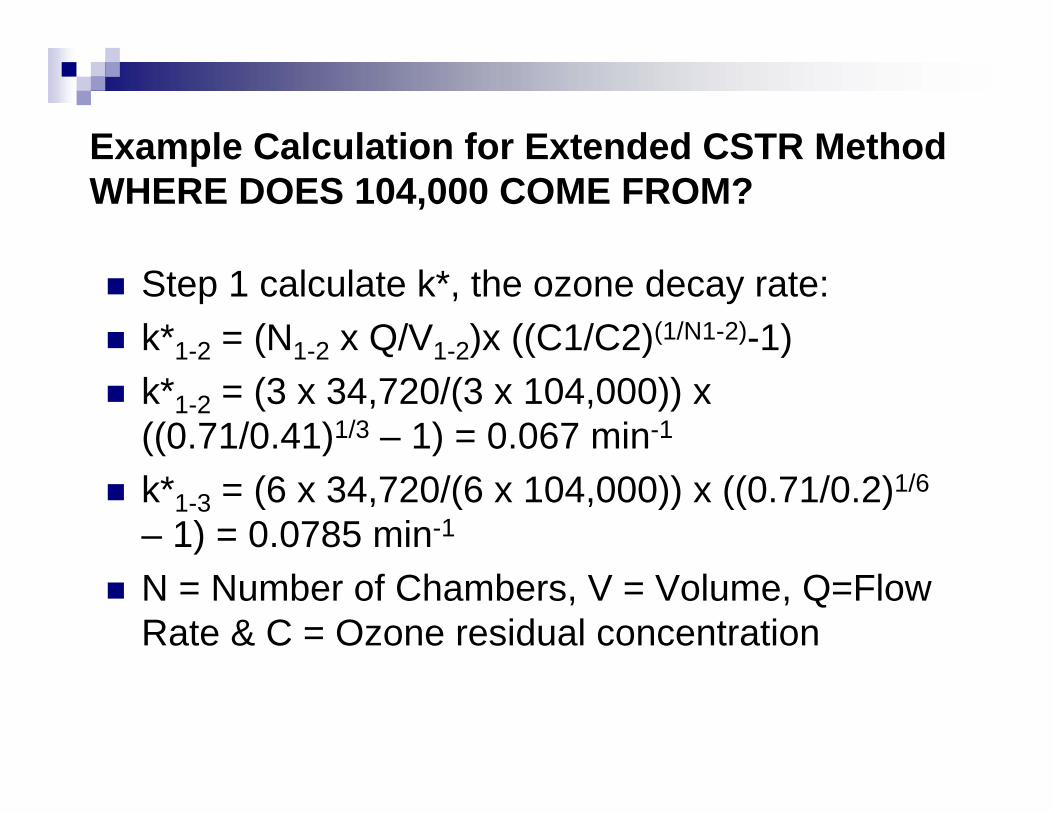
Example Calculation for Extended CSTR MethodWHERE DOES 104,000 COME FROM?
Step 1 calculate k*, the ozone decay rate:k*1-2 = (N1-2 x Q/V1-2)x ((C1/C2)(1/N1-2)-1)k*1-2 = (3 x 34,720/(3 x 104,000)) x ((0.71/0.41)1/3 – 1) = 0.067 min-1
k*1-3 = (6 x 34,720/(6 x 104,000)) x ((0.71/0.2)1/6
– 1) = 0.0785 min-1
N = Number of Chambers, V = Volume, Q=Flow Rate & C = Ozone residual concentration
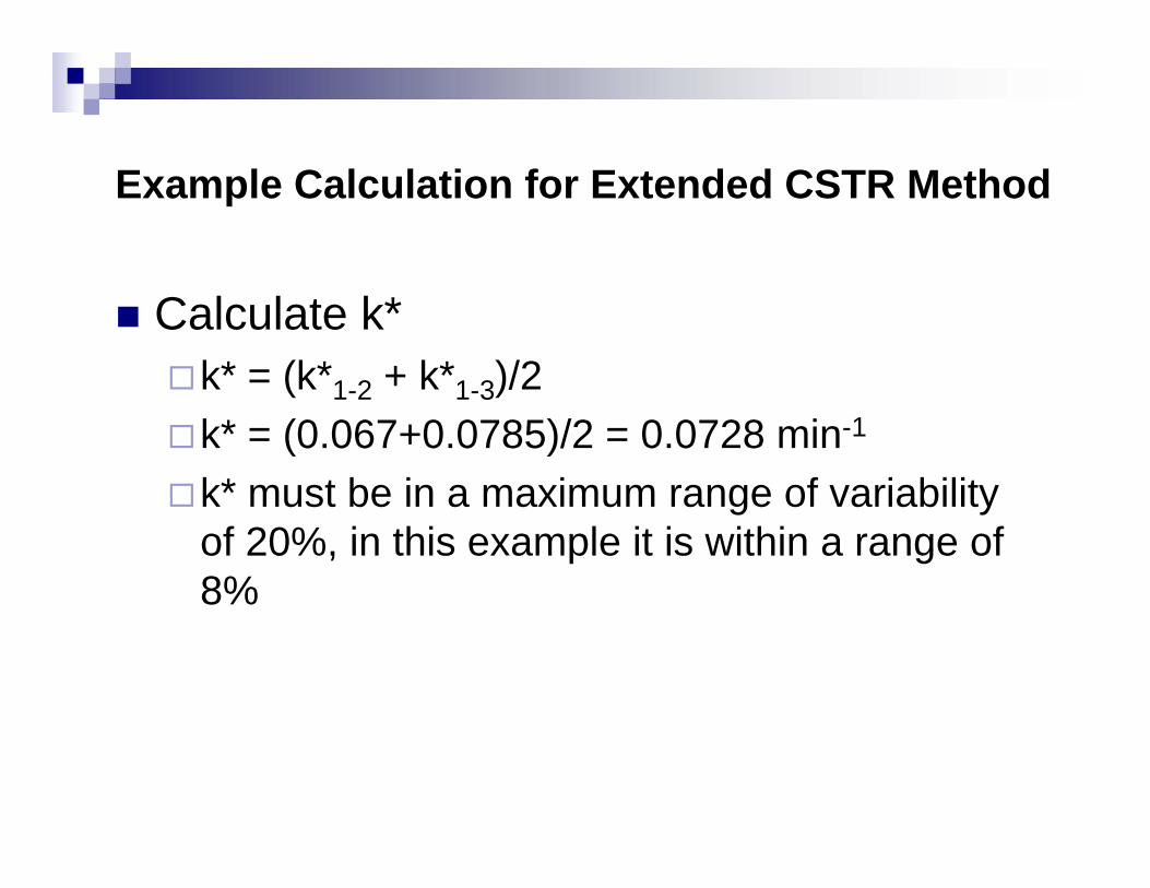
Example Calculation for Extended CSTR Method
Calculate k*k* = (k*1-2 + k*1-3)/2k* = (0.067+0.0785)/2 = 0.0728 min-1
k* must be in a maximum range of variability of 20%, in this example it is within a range of 8%
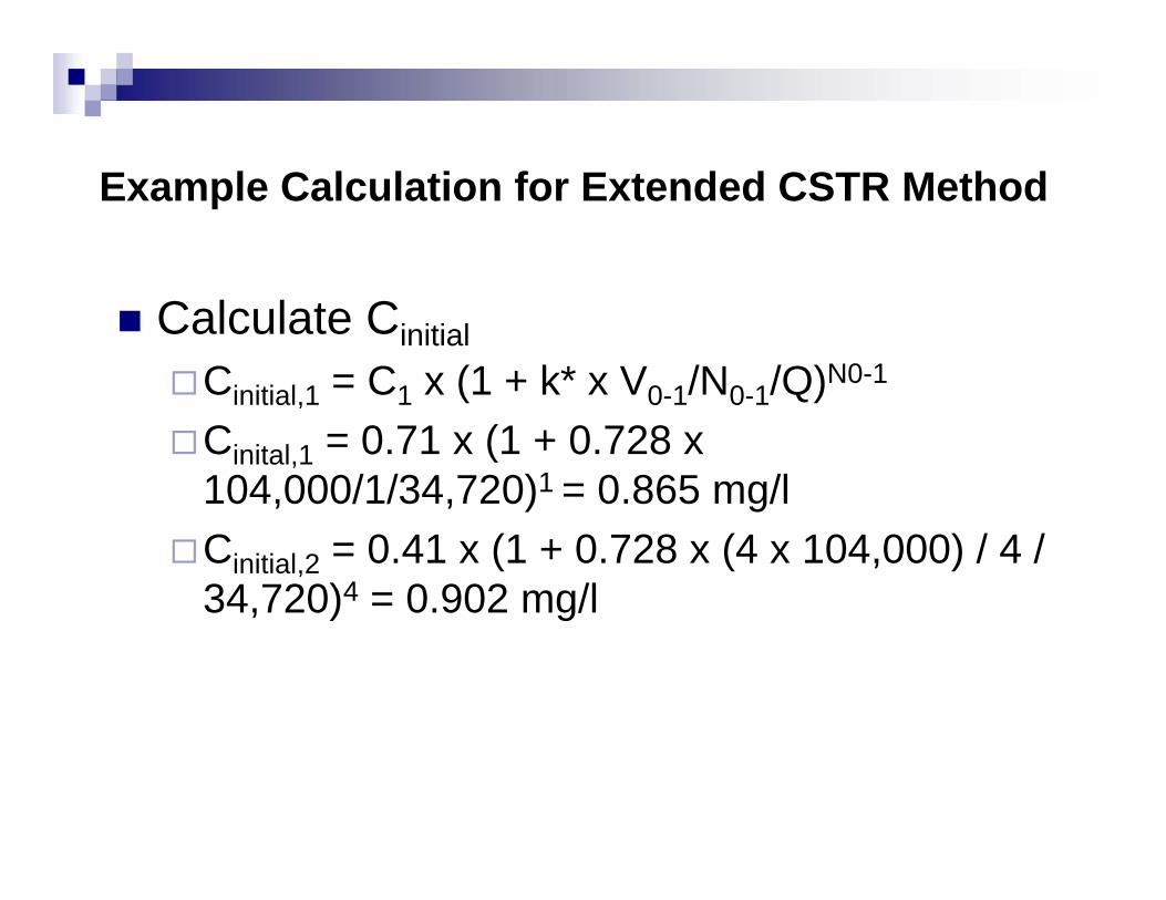
Example Calculation for Extended CSTR Method
Calculate CinitialCinitial,1 = C1 x (1 + k* x V0-1/N0-1/Q)N0-1
Cinital,1 = 0.71 x (1 + 0.728 x 104,000/1/34,720)1 = 0.865 mg/lCinitial,2 = 0.41 x (1 + 0.728 x (4 x 104,000) / 4 / 34,720)4 = 0.902 mg/l
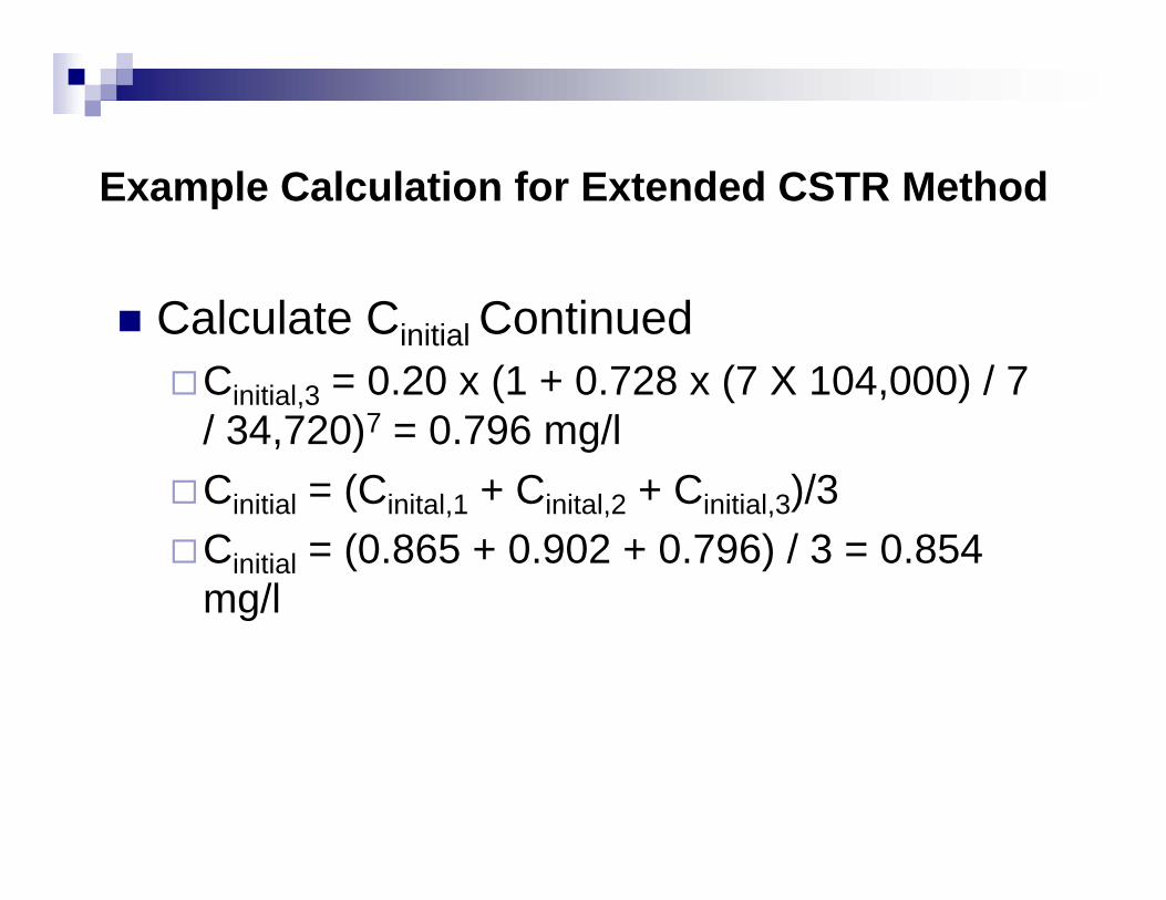
Example Calculation for Extended CSTR Method
Calculate Cinitial ContinuedCinitial,3 = 0.20 x (1 + 0.728 x (7 X 104,000) / 7 / 34,720)7 = 0.796 mg/lCinitial = (Cinital,1 + Cinital,2 + Cinitial,3)/3Cinitial = (0.865 + 0.902 + 0.796) / 3 = 0.854 mg/l
Example Calculation for Extended CSTR Method
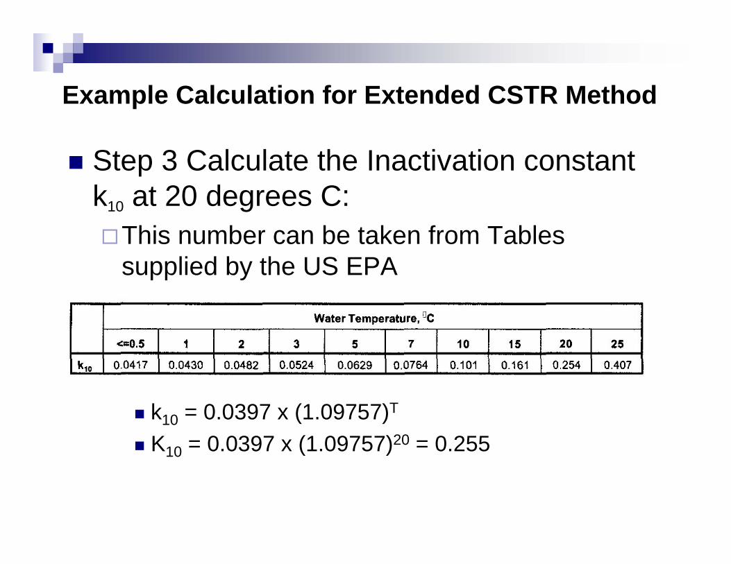
Step 3 Calculate the Inactivation constant k10 at 20 degrees C:
This number can be taken from Tables supplied by the US EPA
Or Calculated from the following equation:k10 = 0.0397 x (1.09757)T
K10 = 0.0397 x (1.09757)20 = 0.255
Example Calculation for Extended CSTR Method
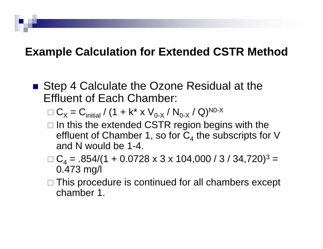
Step 4 Calculate the Ozone Residual at the Effluent of Each Chamber:
CX = Cinitial / (1 + k* x V0-X / N0-X / Q)N0-X
In this the extended CSTR region begins with the effluent of Chamber 1, so for C4 the subscripts for V and N would be 1-4.C4 = .854/(1 + 0.0728 x 3 x 104,000 / 3 / 34,720)3 = 0.473 mg/lThis procedure is continued for all chambers except chamber 1.
Example Calculation for Extended CSTR Method
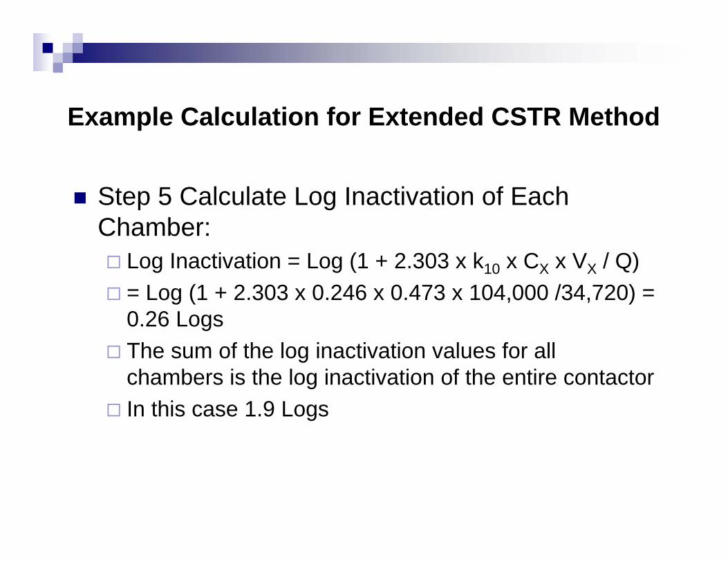
Step 5 Calculate Log Inactivation of Each Chamber:
Log Inactivation = Log (1 + 2.303 x k10 x CX x VX / Q)= Log (1 + 2.303 x 0.246 x 0.473 x 104,000 /34,720) = 0.26 LogsThe sum of the log inactivation values for all chambers is the log inactivation of the entire contactorIn this case 1.9 Logs

![WELCOME! [] · Secondary MCLs Color, odor, cloudiness General physical ph, hardness, alkalinity DBPR THMs, HAAs, bromate, chlorite, residuals SWTR Turbidty, disinfection LCR At-the-tap](https://img.pdfslide.net/doc/110x75/5f375bf91dd4200fe81967a3/welcome-secondary-mcls-color-odor-cloudiness-general-physical-ph-hardness.jpg)