Embed Size (px)
Citation preview
1 … 19
MC
• Ka
rl D
ungs
, Inc
. • M
BC-V
EF...
. • E
ditio
n 20
18.0
5 • P
/N 2
6454
0
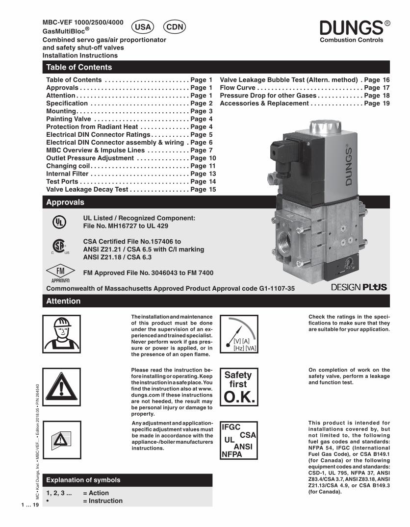
UL Listed / Recognized Component: File No. MH16727 to UL 429
CSACertifiedFileNo.157406to ANSIZ21.21/CSA6.5withC/Imarking ANSI Z21.18 / CSA 6.3
FMApprovedFileNo.3046043toFM7400
CommonwealthofMassachusettsApprovedProductApprovalcodeG1-1107-35
MBC-VEF1000/2500/4000GasMultiBloc®
Combinedservogas/airproportionatorandsafetyshut-offvalvesInstallationInstructions
TableofContents
USA CDN
TableofContents . . . . . . . . . . . . . . . . . . . . . . . . Page1Approvals . . . . . . . . . . . . . . . . . . . . . . . . . . . . . . . Page1Attention . . . . . . . . . . . . . . . . . . . . . . . . . . . . . . . . Page1Specification . . . . . . . . . . . . . . . . . . . . . . . . . . . . Page2Mounting. . . . . . . . . . . . . . . . . . . . . . . . . . . . . . . . Page3PaintingValve . . . . . . . . . . . . . . . . . . . . . . . . . . . Page4ProtectionfromRadiantHeat . . . . . . . . . . . . . . Page4ElectricalDINConnectorRatings . . . . . . . . . . . Page5ElectricalDINConnectorassembly&wiring . Page6MBCOverview&ImpulseLines . . . . . . . . . . . . Page7OutletPressureAdjustment . . . . . . . . . . . . . . . Page10Changingcoil . . . . . . . . . . . . . . . . . . . . . . . . . . . . Page11InternalFilter . . . . . . . . . . . . . . . . . . . . . . . . . . . . Page13TestPorts . . . . . . . . . . . . . . . . . . . . . . . . . . . . . . . Page14ValveLeakageDecayTest . . . . . . . . . . . . . . . . . Page15
Approvals
1, 2, 3 ... = Action • =Instruction
Explanationofsymbols
On completion of work on thesafetyvalve,performaleakageandfunctiontest.
Please read the instructionbe-foreinstallingoroperating.Keeptheinstructioninasafeplace.Youfindtheinstructionalsoatwww.dungs.comIftheseinstructionsarenotheeded, the resultmaybepersonalinjuryordamagetoproperty.Anyadjustmentandapplication-specificadjustmentvaluesmustbemadeinaccordancewiththeappliance-/boilermanufacturersinstructions.
Attention
Check the ratings in thespeci-ficationstomakesurethattheyaresuitableforyourapplication.
This product is intended forinstallations covered by, butnot limited to, the followingfuel gas codesandstandards:NFPA 54, IFGC (InternationalFuelGasCode),orCSAB149.1(for Canada) or the followingequipmentcodesandstandards:CSD-1,UL795,NFPA37,ANSIZ83.4/CSA 3.7, ANSI Z83.18, ANSI Z21.13/CSA 4.9, or CSA B149.3 (forCanada).
[V] [A] [Hz] [VA]
Safetyfirst
O.K.IFGC
CSAULANSI
NFPA
Theinstallationandmaintenanceof this product must be doneunderthesupervisionofanex-periencedandtrainedspecialist.Neverperformworkifgaspres-sure or power is applied, or inthepresenceofanopenflame.
ValveLeakageBubbleTest(Altern.method) . Page16FlowCurve . . . . . . . . . . . . . . . . . . . . . . . . . . . . . . Page17PressureDropforotherGases . . . . . . . . . . . . . Page18Accessories&Replacement . . . . . . . . . . . . . . . Page19
3 … 192 … 19
MC
• Ka
rl D
ungs
, Inc
. • M
BC-V
EF...
. • E
ditio
n 20
18.0
5 • P
/N 2
6454
0
Specification
Safety Valve Max. OperatingPressureMOP = 5 PSI (138 in. W.C.)
Regulator Operating PressureRatingsVEFVersionpin : 6 to 138 in. W.C.pL : 0.16 to 41 in. W.C.pBr: 0.27 to 41 in. W.C.
pin : Gas Inlet PressurepL : Blower PressurepBr: Combustion Chamber Pressure
AmbientTemperature(CSA)-40 °F ... +140 °F(-40 °C … +60 °C)AmbientTemperature(UL)+5 °F ... +140 °F(-15 °C … +60 °C)
GasesDry, natural gas, propane, butane; other noncorrosive gases. A “dry” gas has a dew point lower than +15 °F and its relative humidity is less than 60 %. MaterialsincontactwithGasHousing: Aluminium, Steel, free of nonferrous metals. Sealings on valve seats: NBR-based rubber.
ElectricalRatings110 - 120 VAC / 50 - 60 Hz; 24 VAC / 50 - 60 Hz; 12 VDC, 24 VDCOperatingtime100 % duty cycleCycleRateMaximum 60 cycles/hr (30 s on/off)
Filterinstalled in the housing upstream V150 micron
Classification of Valve V1 and V2Safety Shutoff Valve: UL 429, FM 7400 ANSI Z21.21 • CSA 6.5 C/I ValvesClosingTime(Valve1&Valve2)< 1 sOpening Time (Valve1&Valve2) < 1 s
MBC- Two normally closed safety shutoff valves and gas/air proportionator in one housing. Fast opening, fast closing.
[PSI]
[V] [A] [Hz] [VA]
Gas
°F
0-40
+150
ElectricalConnectionDIN-connector with 1/2” NPT conduit not supplied for CSA, supplied for UL.
Order separately for CSA VersionsPowerConsumptionwithallcoilsenergized
NEMA
EnclosureRatingNEMA Type 12 / IP54
VentLimitingDeviceandVentLineConnectionThe MBC has an internal, factory installed vent limiter re ANSI Z21.18/CSA 6.3. Venting required unless otherwise accepted by the authority having jurisdiction.
PowerConsumptionTableValveBodySize Ratedvoltage InrushPmax.
[VA]fort=3sInrushcurrentpeak(A)
HoldingPmax.[VA]Operation
Recommendedpowerofsupplytransformer(VA)
MBC 100012 VDC
140 20.1 16 DC batteryMBC 2500 160 20.1 20 DC batteryMBC 4000 – – – –MBC 1000
24 VDC130 13.4 16 DC battery
MBC 2500 160 13.4 20 DC batteryMBC 4000 160 14 30 DC batteryMBC 1000
24 VAC*120 14.7 20 250
MBC 2500 160 13.9 20 300MBC 4000 – – – –MBC 1000
110/120 VAC*120 3.1 16 250
MBC 2500 180 3.0 20 300MBC 4000 160 2.4 25 300*Power supply should compensate for the inrush current, and wire gauge should be considered. In order to absorb voltage spikes during inrush, an electrolytic capacitor (4700 µF) between MBC and transformer is recommended.
3 … 19
MC
• Ka
rl D
ungs
, Inc
. • M
BC-V
EF...
. • E
ditio
n 20
18.0
5 • P
/N 2
6454
0
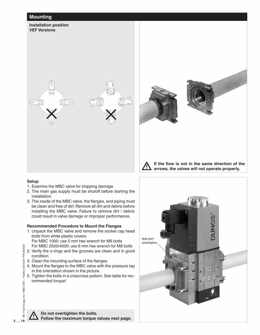
Donotovertightenthebolts.Followthemaximumtorquevaluesnextpage.
If theflowisnot in thesamedirectionof thearrows,thevalveswillnotoperateproperly.
Setup1. Examine the MBC valve for shipping damage.2. The main gas supply must be shutoff before starting the
installation.3. The inside of the MBC valve, the flanges, and piping must
be clean and free of dirt. Remove all dirt and debris before installing the MBC valve. Failure to remove dirt / debris could result in valve damage or improper performance.
RecommendedProceduretoMounttheFlanges1. Unpack the MBC valve and remove the socket cap head
bolts from white plastic covers. For MBC 1000: use 5 mm hex wrench for M6 bolts For MBC 2500/4000: use 6 mm hex wrench for M8 bolts 2. Verify the o-rings and the grooves are clean and in good
condition.3. Clean the mounting surface of the flanges. 4. Mount the flanges to the MBC valve with the pressure tap
in the orientation shown in the picture. 5. Tighten the bolts in a crisscross pattern. See table for rec-
ommended torque!
InstallationpositionVEFVersions
2016 12 8
4
pBr
2016
1284pBr
2016
1284 p Br
2016128
4
pBr
Mounting
test port orientation
5…194 … 19
MC
• Ka
rl D
ungs
, Inc
. • M
BC-V
EF...
. • E
ditio
n 20
18.0
5 • P
/N 2
6454
0
ProtectionfromRadiantHeat• Radiant heat must be considered as a heat source that
could result in an ambient temperature higher than the rat-ing of this valve.
• Provide proper shielding to protect against radiant heat.
PaintingValve
RecommendedPipingProcedure• Use new, properly reamed and threaded pipe free of chips.• Apply good quality pipe sealant, putting a moderate
amount on the male threads only. If pipe sealant lodges on the valve seat, it will prevent proper operation. If using LP gas, use pipe sealant rated for use with LP gas.
• OncompletionofworkontheMBCvalve,performaleakagetest.(See“ValveLeakageTest”)
• Do not thread pipe too far. Valve distortion and/or mal-function may result from excess pipe in the valve body.
• Apply counter pressure only a parallel jaw wrench only to the flats on the flange when connecting to pipe.
• Do not overtighten the pipe. Follow the maximum torque values listed below.
• It is not recommended that this valve be painted. Painting covers date codes and other labels that identify this valve.
• If the valve needs to be painted, a paint free of volitile organic componants (VOC’s) must be used. VOC’s can damage valve o-rings, resulting in external gas leakage over time.
• During the painting process, use measures that will allow the valve’s date code and other labeling information to be legible after the paint is dry.
• Painting the valve may damage valve o-rings, resulting in external gas leakage over time.
RecommendedTorqueforPiping
1/2” 3/4” 1” 11/4” 11/2” 2” NPTpipe
375 560 750 875 940 1190 [Ib-in]
18
19
Chrome S
teel �
Mad
e in G
erman
y
[Ib-in]
18
19
Chrome S
teel �
Mad
e in G
erman
y
[Ib-in] RecommendedTorqueSystemAccessories
M3 M6 M8 ScrewSize
11 lb-in 62 lb-in 134 lb-in [Ib-in]
Alterations,ModificationsorRepairsFor safety-related components, devices and systems, any liability of DUNGS, i.e. product liability for any kind of con-sequential damage as well as liability for defects, will cease to exist if alterations, modifications or repairs are made to these safety-related components, devices and systems by unauthorized specialist staff or with spare parts which have not been specially permitted for use in these safety-related components, devices and systems.
5…19
MC
• Ka
rl D
ungs
, Inc
. • M
BC-V
EF...
. • E
ditio
n 20
18.0
5 • P
/N 2
6454
0
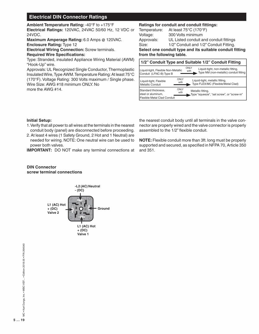
DINConnectorscrewterminalconnections
-L2(AC)Neutral-(DC)
Ground
L1(AC)Hot+(DC)Valve1
L1(AC)Hot+(DC)Valve2
AmbientTemperatureRating: -40°F to +175°FElectricalRatings:120VAC, 24VAC 50/60 Hz, 12 VDC or 24VDC.MaximumAmperageRating:6.0 Amps @ 120VAC.EnclosureRating:Type 12ElectricalWiringConnection: Screw terminals.RequiredWireSpecifications:Type: Stranded, insulated Appliance Wiring Material (AWM) “Hook-Up” wire.Approvals: UL Recognized Single Conductor, Thermoplastic Insulated Wire, Type AWM. Temperature Rating: At least 75°C (170°F). Voltage Rating: 300 Volts maximum / Single phase. Wire Size: AWG #18 minimum ONLY. No more the AWG #14.
Ratingsforconduitandconduitfittings:Temperature: At least 75°C (170°F) Voltage: 300 Volts minimumApprovals: UL Listed conduit and conduit fittingsSize: 1/2” Conduit and 1/2” Conduit Fitting.Selectoneconduittypeanditssuitableconduitfittingfromthefollowingtable.
Liquid-tight, metallic fitting,Type FLEX/MC (Flexible/Metal Clad)
Standard thickness, steel or aluminum, Flexible Metal Clad Conduit
Liquid-tight, Flexible Non-Metallic Conduit (LFNC-B) Type B
Liquid-tight, Flexible Metallic Conduit
Metallic fitting,Type “squeeze”, “set screw”, or “screw-in”
Liquid-tight, non-metallic fitting, Type NM (non-metallic) conduit fitting
1/2”ConduitTypeandSuitable1/2”ConduitFitting
ONLY with
ONLY with
ONLY with
InitialSetup:1. Verify that all power to all wires at the terminals in the nearest
conduit body (panel) are disconnected before proceeding.2. At least 4 wires (1 Safety Ground, 2 Hot and 1 Neutral) are
needed for wiring. NOTE: One neutral wire can be used to power both valves.
IMPORTANT: DO NOT make any terminal connections at
the nearest conduit body until all terminals in the valve con-nector are properly wired and the valve connector is properly assembled to the 1/2” flexible conduit.
NOTE: Flexible conduit more than 3ft. long must be properly supported and secured, as specified in NFPA 70, Article 350 and 351.
ElectricalDINConnectorRatings
7 … 196 … 19
MC
• Ka
rl D
ungs
, Inc
. • M
BC-V
EF...
. • E
ditio
n 20
18.0
5 • P
/N 2
6454
0
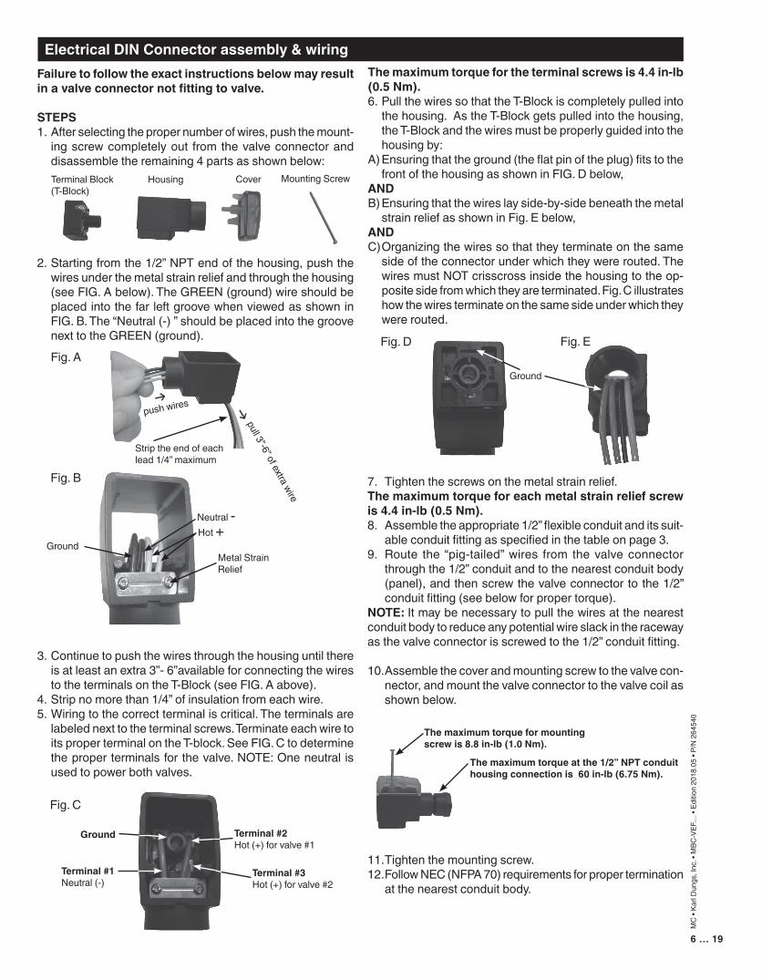
7. Tighten the screws on the metal strain relief.Themaximumtorqueforeachmetalstrainreliefscrewis4.4in-lb(0.5Nm).8. Assemble the appropriate 1/2” flexible conduit and its suit-
able conduit fitting as specified in the table on page 3.9. Route the “pig-tailed” wires from the valve connector
through the 1/2” conduit and to the nearest conduit body (panel), and then screw the valve connector to the 1/2” conduit fitting (see below for proper torque).
NOTE: It may be necessary to pull the wires at the nearest conduit body to reduce any potential wire slack in the raceway as the valve connector is screwed to the 1/2” conduit fitting.
10. Assemble the cover and mounting screw to the valve con-nector, and mount the valve connector to the valve coil as shown below.
11. Tighten the mounting screw. 12. Follow NEC (NFPA 70) requirements for proper termination
at the nearest conduit body.
Failuretofollowtheexactinstructionsbelowmayresultinavalveconnectornotfittingtovalve.
STEPS1. After selecting the proper number of wires, push the mount-
ing screw completely out from the valve connector and disassemble the remaining 4 parts as shown below:
2. Starting from the 1/2” NPT end of the housing, push the wires under the metal strain relief and through the housing (see FIG. A below). The GREEN (ground) wire should be placed into the far left groove when viewed as shown in FIG. B. The “Neutral (-) ” should be placed into the groove next to the GREEN (ground).
3. Continue to push the wires through the housing until there is at least an extra 3”- 6”available for connecting the wires to the terminals on the T-Block (see FIG. A above).
4. Strip no more than 1/4” of insulation from each wire.5. Wiring to the correct terminal is critical. The terminals are
labeled next to the terminal screws. Terminate each wire to its proper terminal on the T-block. See FIG. C to determine the proper terminals for the valve. NOTE: One neutral is used to power both valves.
Mounting ScrewTerminal Block(T-Block)
Cover
Themaximumtorqueatthe1/2”NPTconduithousingconnectionis60in-lb(6.75Nm).
Fig. A
Strip the end of each lead 1/4” maximum
push wires
pull 3”-6” of extra wire
Neutral -
Metal Strain Relief
Ground
Fig. B
Themaximumtorqueformountingscrewis8.8in-lb(1.0Nm).
Housing
Themaximumtorquefortheterminalscrewsis4.4in-lb(0.5Nm).6. Pull the wires so that the T-Block is completely pulled into
the housing. As the T-Block gets pulled into the housing, the T-Block and the wires must be properly guided into the housing by:
A) Ensuring that the ground (the flat pin of the plug) fits to the front of the housing as shown in FIG. D below,
AND B) Ensuring that the wires lay side-by-side beneath the metal
strain relief as shown in Fig. E below, ANDC) Organizing the wires so that they terminate on the same
side of the connector under which they were routed. The wires must NOT crisscross inside the housing to the op-posite side from which they are terminated. Fig. C illustrates how the wires terminate on the same side under which they were routed.
Hot +
ElectricalDINConnectorassembly&wiring
Terminal#2Hot (+) for valve #1
Terminal#3Hot (+) for valve #2
Ground
Terminal#1Neutral (-)
Fig. C
Fig. D
Ground
Fig. E
7 … 19
MC
• Ka
rl D
ungs
, Inc
. • M
BC-V
EF...
. • E
ditio
n 20
18.0
5 • P
/N 2
6454
0
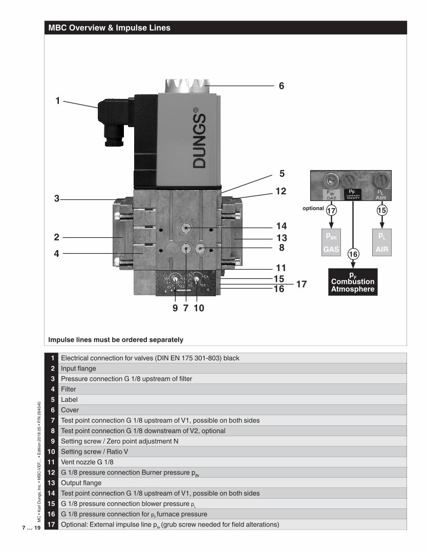
Impulselinesmustbeorderedseparately
MBCOverview&ImpulseLines
1
5
6
14
123
24
7
813
11
9
1516
10
17pFCombustion
Atmosphere
16
pL
AIR
pBR
GAS
17optional 15
1 Electrical connection for valves (DIN EN 175 301-803) black 2 Input flange 3 Pressure connection G 1/8 upstream of filter 4 Filter5 Label 6 Cover 7 Test point connection G 1/8 upstream of V1, possible on both sides 8 Test point connection G 1/8 downstream of V2, optional 9 Setting screw / Zero point adjustment N10 Setting screw / Ratio V11 Vent nozzle G 1/812 G 1/8 pressure connection Burner pressure pBr
13 Output flange14 Test point connection G 1/8 upstream of V1, possible on both sides15 G 1/8 pressure connection blower pressure pL
16 G 1/8 pressure connection for pF furnace pressure17 Optional: External impulse line pBr (grub screw needed for field alterations)
9 … 198 … 19
MC
• Ka
rl D
ungs
, Inc
. • M
BC-V
EF...
. • E
ditio
n 20
18.0
5 • P
/N 2
6454
0
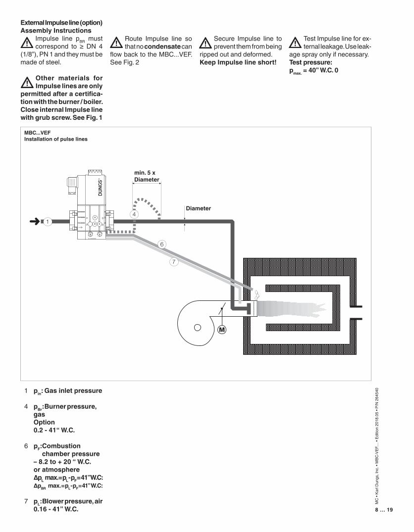
ExternalImpulseline(option)AssemblyInstructions
Impulse line pBR must correspond to ≥ DN 4
(1/8”), PN 1 and they must be made of steel.
Other materials forImpulselinesareonly
permittedafteracertifica-tionwiththeburner/boiler.CloseinternalImpulselinewithgrubscrew.SeeFig.1
Route Impulse line so that no condensate can
flow back to the MBC...VEF. See Fig. 2
Secure Impulse line to prevent them from being
ripped out and deformed.KeepImpulselineshort!
Test Impulse line for ex-ternal leakage. Use leak-
age spray only if necessary.Testpressure:pmax.=40”W.C.0
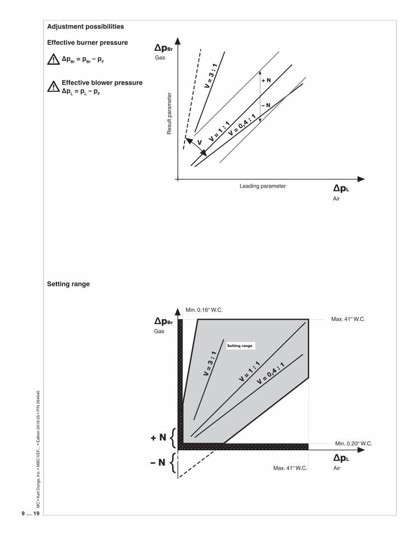
1 pin:Gasinletpressure
4 pBr:Burnerpressure, gas Option 0.2-41“W.C.
6 pF:Combustion chamberpressure –8.2to+20“W.C. oratmosphere ∆pL max.=pL -pF =41”W.C: ∆pBR max.=pL -pF =41”W.C:
7 pL:Blowerpressure,air 0.16-41”W.C.
MBC...VEFInstallationofpulselines
min. 5 x Diameter
Diameter
9 … 19
MC
• Ka
rl D
ungs
, Inc
. • M
BC-V
EF...
. • E
ditio
n 20
18.0
5 • P
/N 2
6454
0
Adjustmentpossibilities
Effectiveburnerpressure
∆pBr = pBr – pF
Effectiveblowerpressure∆pL = pL – pF
Settingrange
Air
Gas
Gas
Air
Max. 41“ W.C.
Max. 41“ W.C.
Leading parameter
Resu
lt pa
ram
eter
Min. 0.20“ W.C.
Min. 0.16“ W.C.
Air
Gas
Gas
Air
Max. 41“ W.C.
Max. 41“ W.C.
Leading parameter
Resu
lt pa
ram
eter
Min. 0.20“ W.C.
Min. 0.16“ W.C.
11 … 1910…19
MC
• Ka
rl D
ungs
, Inc
. • M
BC-V
EF...
. • E
ditio
n 20
18.0
5 • P
/N 2
6454
0
Read all instructions in this manual before installing. Perform steps in the order given. Have installed and serviced/inspected by a
qualified service technician, at least annually. Failure to comply could result in severe personal injury, death or substantial property damage.
A calibrated flue gas analyzer must be utilized to properly adjust appliances featuring DUNGS MBC controls. Failure to properly ap-
ply a flue gas analyzer can result in carbon monoxide emissions causing severe personal injury, death or substantial property damage.
Failure to follow all instructions can result in carbon monoxide emissions causing severe personal injury or death.
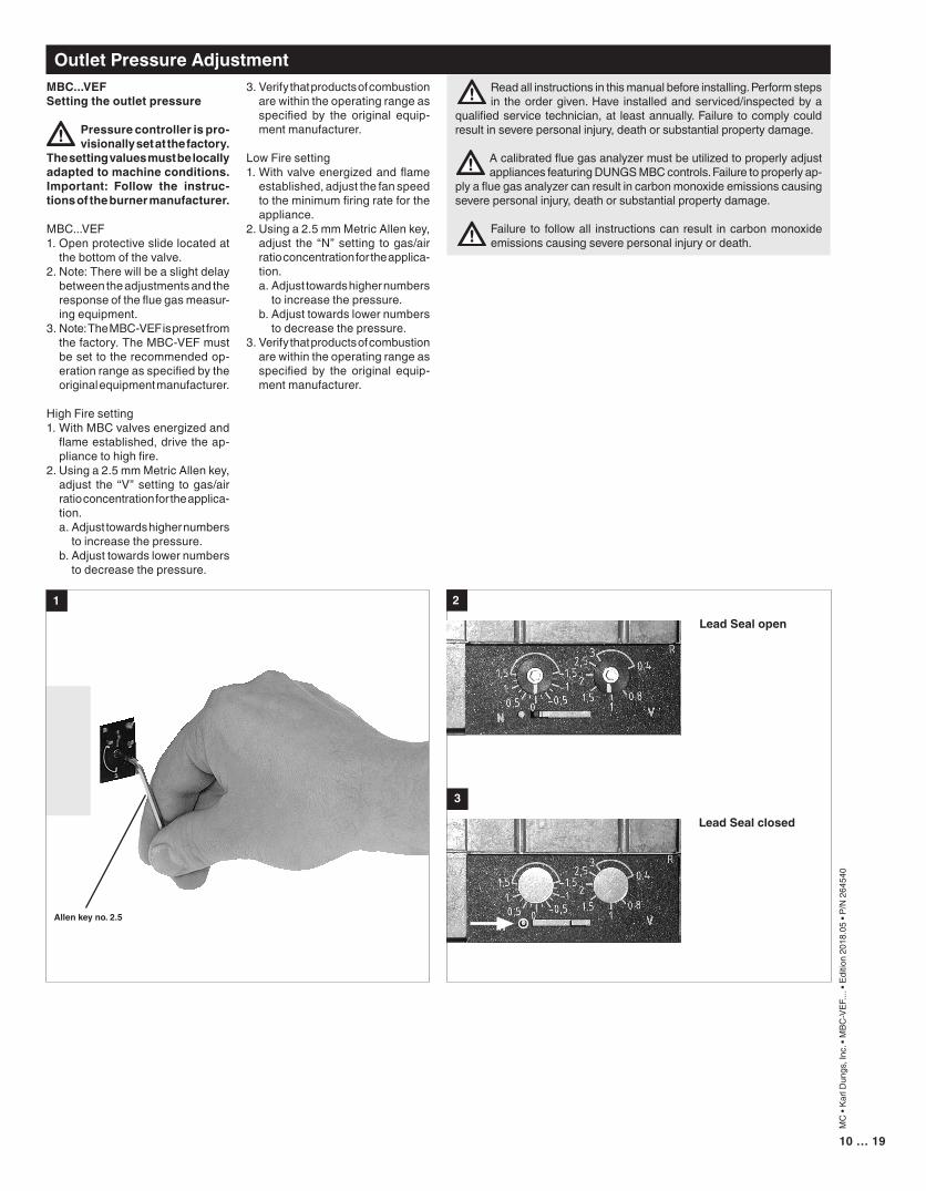
MBC...VEFSettingtheoutletpressure
Pressurecontrollerispro-visionallysetatthefactory.
Thesettingvaluesmustbelocallyadaptedtomachineconditions.Important: Follow the instruc-tionsoftheburnermanufacturer.
MBC...VEF1. Open protective slide located at
the bottom of the valve.2. Note: There will be a slight delay
between the adjustments and the response of the flue gas measur-ing equipment.
3. Note: The MBC-VEF is preset from the factory. The MBC-VEF must be set to the recommended op-eration range as specified by the original equipment manufacturer.
High Fire setting1. With MBC valves energized and
flame established, drive the ap-pliance to high fire.
2. Using a 2.5 mm Metric Allen key, adjust the “V” setting to gas/air ratio concentration for the applica-tion.
a. Adjust towards higher numbers to increase the pressure.
b. Adjust towards lower numbers to decrease the pressure.
1
Allenkeyno.2.5
2
3
LeadSealopen
LeadSealclosed
OutletPressureAdjustment3. Verify that products of combustion
are within the operating range as specified by the original equip-ment manufacturer.
Low Fire setting1. With valve energized and flame
established, adjust the fan speed to the minimum firing rate for the appliance.
2. Using a 2.5 mm Metric Allen key, adjust the “N” setting to gas/air ratio concentration for the applica-tion.
a. Adjust towards higher numbers to increase the pressure.
b. Adjust towards lower numbers to decrease the pressure.
3. Verify that products of combustion are within the operating range as specified by the original equip-ment manufacturer.
11 … 19
MC
• Ka
rl D
ungs
, Inc
. • M
BC-V
EF...
. • E
ditio
n 20
18.0
5 • P
/N 2
6454
0
1
A
A
2
B
3 4
5
B
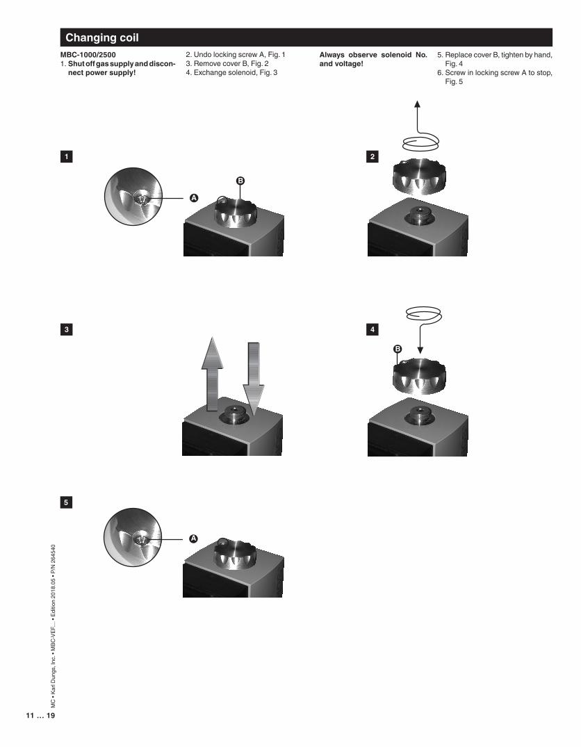
ChangingcoilMBC-1000/25001. Shutoffgassupplyanddiscon-nectpowersupply!
2. Undo locking screw A, Fig. 13. Remove cover B, Fig. 24. Exchange solenoid, Fig. 3
Always observe solenoid No.andvoltage!
5. Replace cover B, tighten by hand, Fig. 4
6. Screw in locking screw A to stop, Fig. 5
13 … 1912 … 19
MC
• Ka
rl D
ungs
, Inc
. • M
BC-V
EF...
. • E
ditio
n 20
18.0
5 • P
/N 2
6454
0
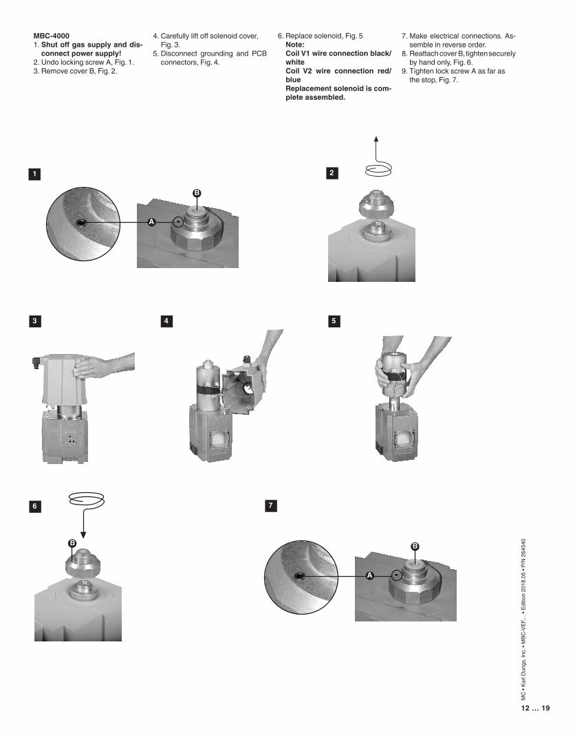
B
4. Carefully lift off solenoid cover, Fig. 3.5. Disconnect grounding and PCB
connectors, Fig. 4.
MBC-40001. Shutoffgassupplyanddis-connectpowersupply!
2. Undo locking screw A, Fig. 1.3. Remove cover B, Fig. 2.
1 2
3 4 5
6
B
A
B
A
7
6. Replace solenoid, Fig. 5 Note: CoilV1wireconnectionblack/white
Coil V2 wire connection red/blue
Replacementsolenoidiscom-pleteassembled.
7. Make electrical connections. As-semble in reverse order.
8. Reattach cover B, tighten securely by hand only, Fig. 6.
9. Tighten lock screw A as far as the stop, Fig. 7.
13 … 19
MC
• Ka
rl D
ungs
, Inc
. • M
BC-V
EF...
. • E
ditio
n 20
18.0
5 • P
/N 2
6454
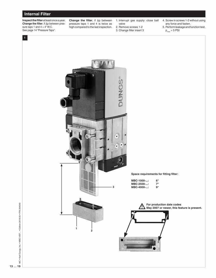
0Inspectthefilter at least once a year.Changethefilter, if ∆p between pres-sure taps 1 and 4 > 4” W.C. See page 14 “Pressure Taps”.
12
3
Spacerequirementsforfittingfilter:
MBC-1000-...: 6“MBC-2500-...: 7“MBC-4000-...: 9“
InternalFilterChange the filter, if ∆p between pressure taps 1 and 4 is twice as high compared to the last inspection.
1. Interrupt gas supply: close ball valve
2. Remove screws 1-23. Change filter insert 3
4. Screw in screws 1-2 without using any force and fasten.
5. Perform leakage and function test, pmax = 5 PSI
ForproductiondatecodesMay2007ornewer,thisfeatureispresent.
1
15…1914 … 19
MC
• Ka
rl D
ungs
, Inc
. • M
BC-V
EF...
. • E
ditio
n 20
18.0
5 • P
/N 2
6454
0
4
21
3
4
21
3
5
TestPortsThe G 1/8 ISO 228 taps are available on both sides up-stream V1, between V1 and V2, downstream V2, and on both flanges. The G 1/8 test
Pressuretaps
MBC-1000/2500…
MBC-4000…
nipple (P/N 219008) can be screwed in any of these pres-sure tap ports.
4
21
3 3
4
21
1,2,4,5G 1/8 Screw plugPressure Switch Connection
3G 1/8 Screw plug Pressure Switch Connection optional with P/N 214975
6, 7 Vent nozzle G 1/8
2 3
3
5
2
4
1
1
67
15…19
MC
• Ka
rl D
ungs
, Inc
. • M
BC-V
EF...
. • E
ditio
n 20
18.0
5 • P
/N 2
6454
0This test method is an alternative to bubble tightness testing in case there is no manually operated shutoff valve installed downstream of the MBC.Preparation for leak testing:1) Ensure that the appliance is not in operation.2) This test requires: • A manometer capable of reading +/- 0.1”WC. • A stopwatch. • A hose barb connection that fits to manometer and
the valve test port.3) The manual shutoff valve upstream of the MBC must re-
main open during this test. In addition, the manual shutoff valve downstream of the MBC, if installed, must remain open during this test.
4) The test also requires the ability to open and close safety valve #1 and safety valve #2 independently using the volt-age as indicated on the coil.
5) Externally leak test the valve and all piping connected to the valve including the upstream manual shutoff valve and the manometer connection. DUNGS recommends using an all purpose liquid leak detector solution (Snoop™ or a non-aggressive soapy water solution). The presence of bubbles indicates a leak.
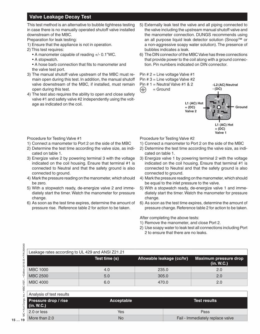
6) The DIN connector of the MBC Valve has three connections that provide power to the coil along with a ground connec-tion. Pin numbers indicated on DIN connector.
Pin # 2 = Line voltage Valve #1Pin # 3 = Line voltage Valve #2Pin # 1 = Neutral Valve #1 & 2
= Ground
Procedure for Testing Valve #11) Connect a manometer to Port 2 on the side of the MBC2) Determine the test time according the valve size, as indi-
cated on table 1.3) Energize valve 2 by powering terminal 3 with the voltage
indicated on the coil housing. Ensure that terminal #1 is connected to Neutral and that the safety ground is also connected to ground.
4) Mark the pressure reading on the manometer, which should be zero.
5) With a stopwatch ready, de-energize valve 2 and imme-diately start the timer. Watch the manometer for pressure change.
6) As soon as the test time expires, determine the amount of pressure rise. Reference table 2 for action to be taken.
Procedure for Testing Valve #21) Connect a manometer to Port 2 on the side of the MBC 2) Determine the test time according the valve size, as indi-
cated on table 1.3) Energize valve 1 by powering terminal 2 with the voltage
indicated on the coil housing. Ensure that terminal #1 is connected to Neutral and that the safety ground is also connected to ground.
4) Mark the pressure reading on the manometer, which should be equal to the inlet pressure to the valve.
5) With a stopwatch ready, de-energize valve 1 and imme-diately start the timer. Watch the manometer for pressure change.
6) As soon as the test time expires, determine the amount of pressure change. Reference table 2 for action to be taken.
After completing the above tests:1) Remove the manometer, and close Port 2.2) Use soapy water to leak test all connections including Port
2 to ensure that there are no leaks.
ValveLeakageDecayTest
Leakage rates according to UL 429 and ANSI Z21.21Testtime(s) Allowableleakage(cc/hr) Maximumpressuredrop
(in.W.C.)MBC 1000 4.0 235.0 2.0MBC 2500 5.0 305.0 2.0MBC 4000 6.0 470.0 2.0
Analysis of test resultsPressuredrop/rise(in.W.C.)
Acceptable Testresults
2.0 or less Yes PassMore than 2.0 No Fail - Immediately replace valve
-L2(AC)Neutral-(DC)
Ground
L1(AC)Hot+(DC)Valve1
L1(AC)Hot+(DC)Valve2
17 … 1916 … 19
MC
• Ka
rl D
ungs
, Inc
. • M
BC-V
EF...
. • E
ditio
n 20
18.0
5 • P
/N 2
6454
0
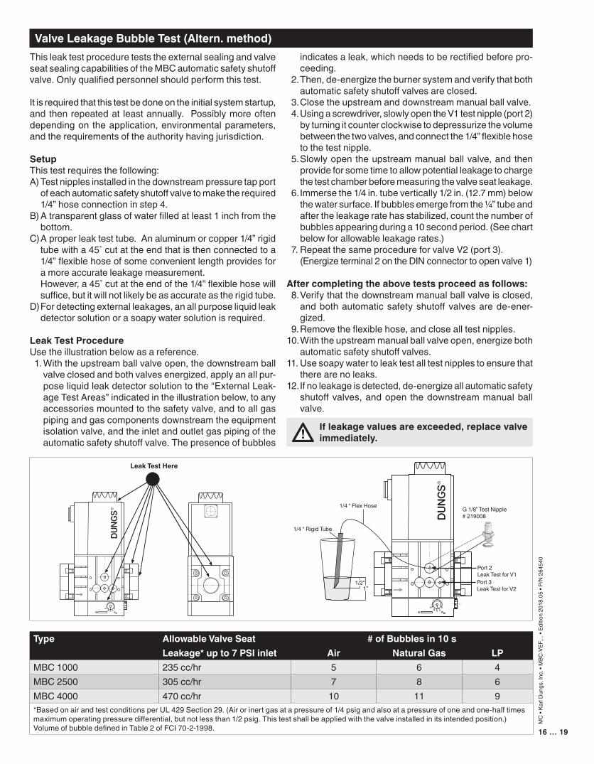
ValveLeakageBubbleTest(Altern.method)This leak test procedure tests the external sealing and valve seat sealing capabilities of the MBC automatic safety shutoff valve. Only qualified personnel should perform this test.
It is required that this test be done on the initial system startup, and then repeated at least annually. Possibly more often depending on the application, environmental parameters, and the requirements of the authority having jurisdiction.
SetupThis test requires the following:A) Test nipples installed in the downstream pressure tap port
of each automatic safety shutoff valve to make the required 1/4” hose connection in step 4.
B) A transparent glass of water filled at least 1 inch from the bottom.
C) A proper leak test tube. An aluminum or copper 1/4” rigid tube with a 45˚ cut at the end that is then connected to a 1/4” flexible hose of some convenient length provides for a more accurate leakage measurement.
However, a 45˚ cut at the end of the 1/4” flexible hose will suffice, but it will not likely be as accurate as the rigid tube.
D) For detecting external leakages, an all purpose liquid leak detector solution or a soapy water solution is required.
LeakTestProcedureUse the illustration below as a reference. 1. With the upstream ball valve open, the downstream ball
valve closed and both valves energized, apply an all pur-pose liquid leak detector solution to the “External Leak-age Test Areas” indicated in the illustration below, to any accessories mounted to the safety valve, and to all gas piping and gas components downstream the equipment isolation valve, and the inlet and outlet gas piping of the automatic safety shutoff valve. The presence of bubbles
indicates a leak, which needs to be rectified before pro-ceeding.
2. Then, de-energize the burner system and verify that both automatic safety shutoff valves are closed.
3. Close the upstream and downstream manual ball valve. 4. Using a screwdriver, slowly open the V1 test nipple (port 2)
by turning it counter clockwise to depressurize the volume between the two valves, and connect the 1/4” flexible hose to the test nipple.
5. Slowly open the upstream manual ball valve, and then provide for some time to allow potential leakage to charge the test chamber before measuring the valve seat leakage.
6. Immerse the 1/4 in. tube vertically 1/2 in. (12.7 mm) below the water surface. If bubbles emerge from the 1/4” tube and after the leakage rate has stabilized, count the number of bubbles appearing during a 10 second period. (See chart below for allowable leakage rates.)
7. Repeat the same procedure for valve V2 (port 3). (Energize terminal 2 on the DIN connector to open valve 1)
Aftercompletingtheabovetestsproceedasfollows: 8. Verify that the downstream manual ball valve is closed,
and both automatic safety shutoff valves are de-ener-gized.
9. Remove the flexible hose, and close all test nipples. 10. With the upstream manual ball valve open, energize both
automatic safety shutoff valves.11. Use soapy water to leak test all test nipples to ensure that
there are no leaks.12. If no leakage is detected, de-energize all automatic safety
shutoff valves, and open the downstream manual ball valve.
Type AllowableValveSeat #ofBubblesin10sLeakage*upto7PSIinlet Air NaturalGas LP
MBC 1000 235 cc/hr 5 6 4MBC 2500 305 cc/hr 7 8 6MBC 4000 470 cc/hr 10 11 9*Based on air and test conditions per UL 429 Section 29. (Air or inert gas at a pressure of 1/4 psig and also at a pressure of one and one-half times maximum operating pressure differential, but not less than 1/2 psig. This test shall be applied with the valve installed in its intended position.)Volume of bubble defined in Table 2 of FCI 70-2-1998.
Ifleakagevaluesareexceeded,replacevalveimmediately.
2016 12 8
4
pBr
Leak Test Here
2016 12 8
4
pBr
1/2”1”
1/4 “ Rigid Tube
1/4 “ Flex Hose G 1/8” Test Nipple# 219008
Port 2 Leak Test for V1Port 3 Leak Test for V2
17 … 19
MC
• Ka
rl D
ungs
, Inc
. • M
BC-V
EF...
. • E
ditio
n 20
18.0
5 • P
/N 2
6454
0
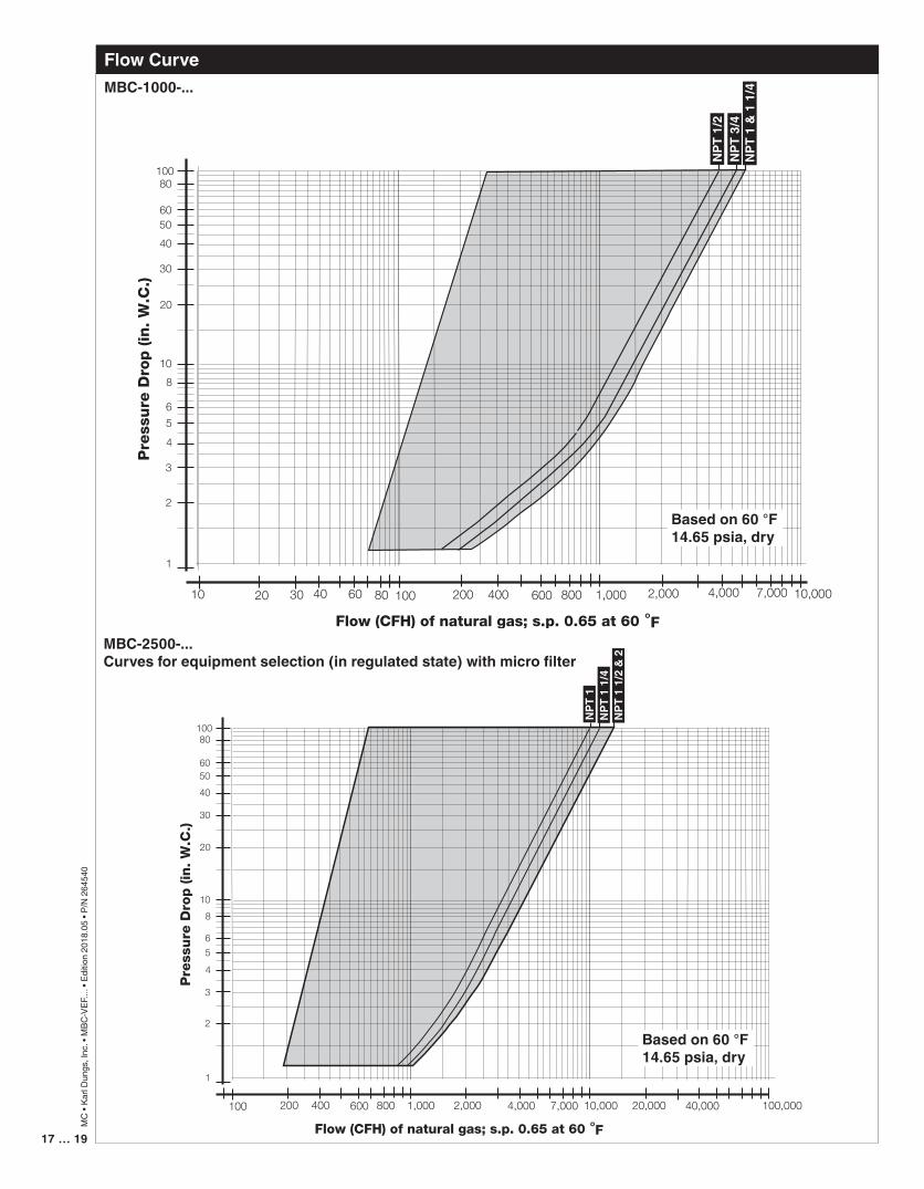
FlowCurve
10 20 30 40 60 80 100 200 400 600 2,000 10,0004,000 7,000800 1,000
NPT
1/2
NPT
3/4
NPT
1 &
1 1
/4
Basedon60°F14.65psia,dry
MBC-1000-...
MBC-2500-...Curvesforequipmentselection(inregulatedstate)withmicrofilter
100 200 400 600 2,000 10,0004,000 7,000800 1,000
NPT
1N
PT 1
1/4
NPT
1 1
/2 &
2
20,000 40,000 100,000
Basedon60°F14.65psia,dry
19 … 1918 … 19
MC
• Ka
rl D
ungs
, Inc
. • M
BC-V
EF...
. • E
ditio
n 20
18.0
5 • P
/N 2
6454
0
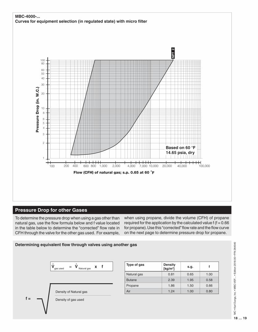
PressureDropforotherGasesTo determine the pressure drop when using a gas other than natural gas, use the flow formula below and f value located in the table below to determine the “corrected” flow rate in CFH through the valve for the other gas used. For example,
when using propane, divide the volume (CFH) of propane required for the application by the calculated value f (f = 0.66 for propane). Use this “corrected” flow rate and the flow curve on the next page to determine pressure drop for propane.
Density of Natural gas
Density of gas usedf=
Typeofgas Density[kg/m3] s.g. f
Natural gas 0.81 0.65 1.00Butane 2.39 1.95 0.58Propane 1.86 1.50 0.66Air 1.24 1.00 0.80
Determiningequivalentflowthroughvalvesusinganothergas
Vgas used = V Natural gas x f° °
MBC-4000-...Curvesforequipmentselection(inregulatedstate)withmicrofilter
100 200 400 600 2,000 10,0004,000 7,000800 1,000
NPT
2
20,000 40,000 100,000
Basedon60°F14.65psia,dry
19 … 19
MC
• Ka
rl D
ungs
, Inc
. • M
BC-V
EF...
. • E
ditio
n 20
18.0
5 • P
/N 2
6454
0
KarlDungsGmbH&Co.KGP.O.Box1229D-73602Schorndorf,GermanyPhone+49(0)7181-804-0Fax +49(0)[email protected]://www.dungs.com
KarlDungs,Inc.3890PheasantRidgeDriveNESuite150Blaine,MN55449,U.S.A.Phone763582-1700Fax [email protected]://www.dungs.com/usa/
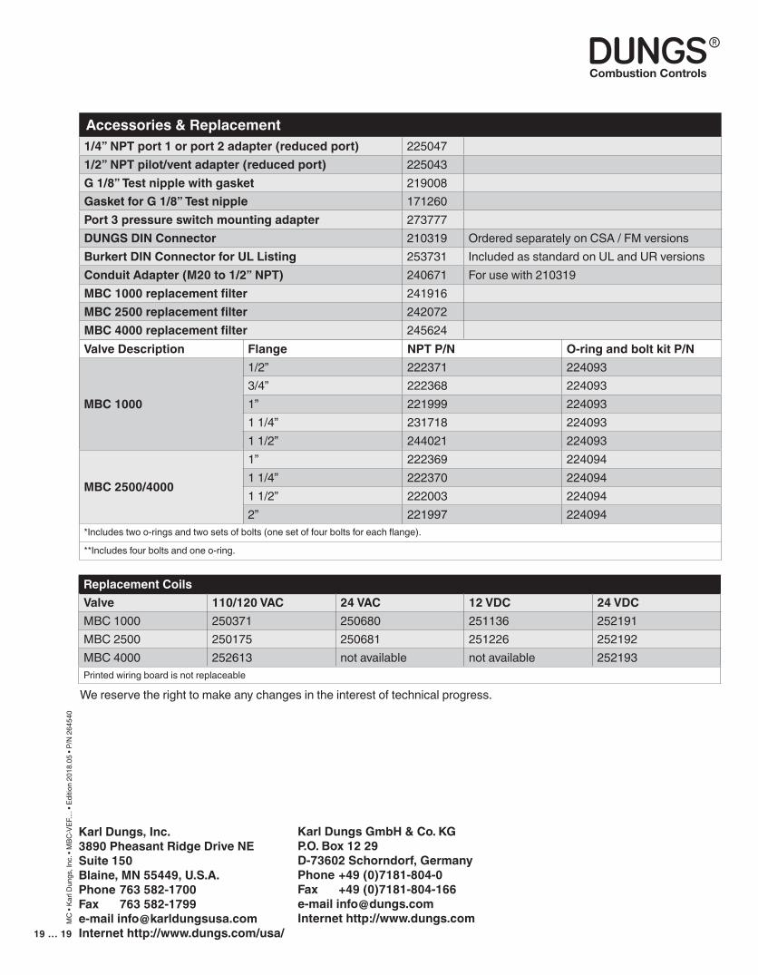
Accessories&Replacement1/4”NPTport1orport2adapter(reducedport) 2250471/2”NPTpilot/ventadapter(reducedport) 225043G1/8”Testnipplewithgasket 219008GasketforG1/8”Testnipple 171260Port3pressureswitchmountingadapter 273777DUNGSDINConnector 210319 Ordered separately on CSA / FM versionsBurkertDINConnectorforULListing 253731 Included as standard on UL and UR versionsConduitAdapter(M20to1/2”NPT) 240671 For use with 210319MBC1000replacementfilter 241916MBC2500replacementfilter 242072MBC4000replacementfilter 245624ValveDescription Flange NPTP/N O-ringandboltkitP/N
MBC1000
1/2” 222371 2240933/4” 222368 2240931” 221999 2240931 1/4” 231718 2240931 1/2” 244021 224093
MBC2500/4000
1” 222369 2240941 1/4” 222370 2240941 1/2” 222003 2240942” 221997 224094
*Includes two o-rings and two sets of bolts (one set of four bolts for each flange).
**Includes four bolts and one o-ring.
ReplacementCoilsValve 110/120VAC 24VAC 12VDC 24VDCMBC 1000 250371 250680 251136 252191MBC 2500 250175 250681 251226 252192MBC 4000 252613 not available not available 252193Printed wiring board is not replaceable
We reserve the right to make any changes in the interest of technical progress.