Embed Size (px)
Citation preview
AD
USAAVLABS TECHNICAL REPORT 65-74
A METHOD FOR PREDICTING THE AERODYNAMIC LOADSAND DYNAMIC RESPONSE OF ROTOR BLADES
By
R. A. Piziah. ','", -.... 'r ""v "'s w t
January 1966
I U. S. ARMY AVIATION MATERIEL LABORATORIES
FORT EUSTIS, VIRGINIA
CONTRACT DA 44-177-AMC-163(T)
CORNELL AERONAUTICAL LABORATORY, INC.BUFFALO, NEW YORK
Distribution of thisdocument is unlimited.
Disclaimers
The findings in this report are not to be construed as an official Depart-ment of the Army position, unless so designated by other authorizeddocuments.
When Government drawings, specifications, or other data are used for anypurpose other than in conncction with a definitely related Government pro-
curement operation, the United States Government thereby incurs no re-sponsibility nor any obligation whatsoever; and the fact that the Governmentmay have formulated, furnished, or in any way supplied the said drawings,specifications, or other data is not to be regarded by implication or other-wise as in any manner licensing the holder or any other person or corpora-tion, or conveying any rights or pernission, to manufacture, use, or sell
any patented invention that may in any way be related thereto.
Disposition Instructions
Destroy this report when it is no longer needed. Do not return it to theoriginator.
-4 J4
DEPARTMENT OF THE ARMYU. S. ARMY AVIATION MATERIEL LABORATORIES
FORT EUSTIS. VIRGINIA 23604
This report has been reviewed by the U.S. Army Aviation Materiel
Laboratories and is considered to be technically sound. The
report is published for the exchange of information and the
stimulation of ideas.
Task lP125901AI4604Contract DA 44-177-AMC-163(T)
USAAVLABS Technical Report 65-74
January 1966
I;
A METHOD FOR PREDICTING THE AERODYNAMIC LOADS
AND DYNAMIC RESPONSE OF ROTOR BLADES
CAL Report BB-1932-S-iby
R. A. Piziali
Prepared by
Cornell Aeronautical Laboratory, Inc.Buffalo, New York
for
U. S. ARMY AVIATION MATERIEL LABORATORIESFORT EUSTIS, VIRGINIA
Distribution of thisdocument is unlimited.
"LI
SUMMARY
An earlier effort (refer nce 1) proved the feasibility of a procedurefor predicting the nonuniform induced velocity distributions and thecorresponding airloads experienced by rotor blades. The presenteffort was undertaken to improve the aerody.-amic representationsused in this earlier work, improve the computational efficiency, and"close the loop" to enable the airloads and corresponding blade motionsto be predicted simultaneously.
The aerodynamic representation was improved by satisfying thechordwise boundary condition (instead of using the lifting line repre..sentation). Considerable simplification was incorporated into thewake reprcsentation which resulted in a substantial increase in thecomputing efficiency and no loss of accuracy in the results. Theequations of motion for the b]ade flapping and flapwise bendingdegrees of freedom were incorporated, and an iterative procedurewas developed which yields a simultaneous solation for the aero-dynamic loads and dynamic response experienced by the rotorblades.
The lift loading and bending moments were computed for the H-34rotor at a = 0. 18 and , = 0. 29, and the HU-1A rotor system at/ = 0. 08 and P = 0. 26. Comparisons of these results with measuredresults are presented both as distributions of the harmonic componentsand as tirnme histories. Results of computations to investigate thesensitivity of the computed airloads and bending moments to variationsin scme of the wake parameters are presented and discussed.
' iii
FOREWORD
The work described in this report was performed by the Cornell Aero-nautical Laboratory, Inc. (CAL), Buffalo, New York, for the U. S. ArmyAviation Materiel Laboratories, (USAAVLABS), Fort Eustis, Virginia,over the 15 month period beginning 30 March 1964. This work is anextension of work accomplished at CAL orer a period of years beginningin 1960 under Contract DA 44-177-TC-698.
Mr. R. A. Piziali was project engineer and author of this report.Mr. J. Balcerak and Mr. R. Whalen assisted in programming thecomputational procedure for the IBM 7044 EDP. The contributions ofDr. H. Daughaday and the many discussions with Messrs. R. P. White,Jr., F. A. DuWaldt, A. R. Trenka, and Dr. I. C. Statler of CAL werehelpful and are appreciated by the author. Mr. J. Yeates administeredthe project for USAAVLABS.
v

BLANK PAGE
1.
tr
CONTENTS
Page
SUMMARY iii
FOREWORD v
LIST OF ILLUSTRATIONS viii
SYMBOLS x
INTRODUCTION 1
ASSUMPTIONS z
WAKE REPRESENTATION 4
BLADE REPRESENTATION 8
COMPUTATIONAL PROCEDURE 15
COMPUTER PROGRAM 19
COMPUTED RESULTS AND COMPARISON WITH MEASUREDRESULTS 20
Ii CONCLUSIONS AND RECOMMENDATIONS 31
REFERENCES 33
DISTRIBUTION 70
APPENDIXES
I. Two-Dimer-'ional Oscillating Wing Investigation of 72Wake Shed Vortex Representation
H1. The Chordwise Induced Velocity Distribution Due to 81A Wake Vortex Element
III. Efficient Method for Numcrically Computing 86Derivatives of Periodic Functions
IV. Flow Diagram for the Computer Program 88(Parts I and 2)
vii
ILLUSTRATIONS
Figure Page
I Example of Possible Walce Configurations 35
2 The Tip-Path-Plane Oriented Coordinate System Used 36for Computing the Induced Velocities
3 Example of the J< -Subscript Notation for Airload Points 36In Rotor Disk When AIR = 3, A/A = 8
4 Coordinate System Used in Blade Representation 37
5 Relation Between Wake Vortex Strengths and the NRA 37Bound Vortex Strengths When YR = 3, NA L 8
6 Major Steps in the Iterative Procedure of Solving the 38Equations
7 Segmentation of Rotor Blades for Computations 39
8 Measured and Compcea Lift and Bending Moments; 40_HU-lA at/6 = 0.26
9 Measured and Computed Lift and Bendirg Moments; 44HU-1A at tL = 0.08
10a Computed Quasi-Steady f , Total P, and Lift at 48r1R = 0.95; HU-IA at / = 0.08
10b Computed Induced Velocity at r/R = 0. 95; HU-IA at 49/z = 0. 08
11 Measured and Computed Lift and Fending Moments; 50H-34 at/z = 0.29
12 Measured and Computed Lift and Bending Moments; 54H-34 at # = 0.18
13a Computed Quasi-Steady ," , Total P, and Lift at 58r/R = 0.95; H-34 at /j, = 0. 18
13b Computed Induced Velocity at r/R = 0.95; H-34 at 59/z = 0. 18
14a Computed Pitching Moments; HU-lA at Iu= 0,26 60
14b Computed Pitching Moments; HU-IA at /-z 0.08 61
viii
Figure Page
14c Computed Pitching Moments; H-34 at i, = 0. 29 62
14d Computed Pitching Moments; H-34 at/t, = 0. 18 63
15 Computed Pitching Moments about Midchord; H-34 64at a = 0. 18
16a Comparison of Computed Lift at r/A = 0.95 for 65Wake with and without a Concentrated Root TrailingVortex; HU-IA at/ = 0.26
16b Comparison of Computed Bending Moment at r/R = 0. 2I 65with and without a Concentrated Root Trailing Vortex;HU-IA at / = 0. 26
17 Distorted Tip Vortices on Retreating Side of Rotor 66Disk as Used in Computation; Blades in the Y = 90and 2700 Positions; HU-lA at /4 = 0. 03
18 Comparison of Lift at r/R = 0. 95 Computed with 67and without Wake Distortion; HU-IA at /, = 0. 08
19 Comparison of Lift at r/R = 0. 95 Computed for Two 67Positions of the Tip Vortex in the Wake; HU-IA at/z = 0. 08
20 Comparison of the Induced Velocity at r/R = 0. 95 for 68Two Radial Positions of the Tip Vortex in the Wake;HU-1A at#z = 0.08
21 Relative Orientation of the Blade and Recent Tip 69Vortices on Advancing Side of the Disk; HU-lA at/4 =0.08
APPENDIXES
I, I Two-Dimensional Oscillating Airfoil Lift and Pitching 77Moment Transfer Functions; Zero Wake Advance (DrA. )
I, 2 Iwo-Dimensional Oscillating Airfoil Lift and Pitching 79Moment Transfer Functions; 0.70 Wake Advance (D= !+12/3)
IV, 1 Flow Diagram for Part I of Computer Program 90
IV. 2 Flow Diagram for Part 2 of Computer Program 93
ix
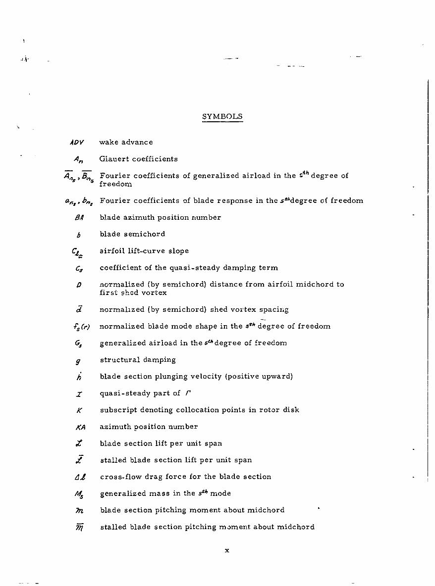
SYMBOLS
ACV wake advance
An Glauert coefficients
A.7, B114 Fourier coefficients of generalized airload in the S degree offreedom
ab,, , Fourier coefficients of blade response in the stdegree of freedom
BI4 blade azimuth position number
b blade s emichord
C airfoil lift-curve slope
cs coefficient of the quasi-steady damping term
D normalized (by semichord) distance from airfoil midchord tofirst shed vortex
d normalized (by semichord) shed vortex spacing
s(r) normalized blade mode shape in the .5h degree of freedom
generalized airload in the s"degree of freedom
9 structural damping
h blade section plunging velocity (positive upward)
x quasi-steady part of r
K subscript denoting collocation points in rotor disk
KA azimuth position number
blade section lift per unit spanl
stalled blade section lift per unit span
,d f cross-flow drag force for the blade section
'S generalized mass in the s mode
n blade section pitching moment about midchord
j stalled blade section pitching moment about midchord
x
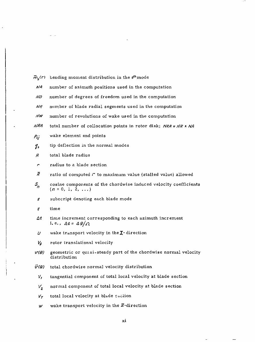
rns(r) bending moment distribution in the ehmode
MA number of azimuth positions used in the computation
AD number of degrees of freedom used in the computation
M? number of blade radial segments used in the computation
M1W number of revolutions of wake used in the computation
A/RA total number of collocation points in rotor disk; NRA = A'R x NA
Pij wake element end points
Is tip deflection in the normal modes
R total blade radius
r radius to a blade section
Aratio of computed J" to maximum value (stalled value) allowed
S cosine components of the chordwise induced velocity coefficients(n =0, 1, 2, .. ,)
S subscript denoting each blade mode
r time
dt time increment corresponding to each azimuth incrementi.e., 4t= At= JI
U wake transport velocity in theI- direction
V t rotor translational velocity
v'(0) geometric or qu&si-steady part of the chordwise normal velocitydistribution
r(O) total chordwise normal velocity distribution
V, tangential component of total local velocity at blade section
V2 normal component of total local velocity at blade section
V7 total local velocity at blade c; :ion
W wake transport velocity in the Z-direction
xi
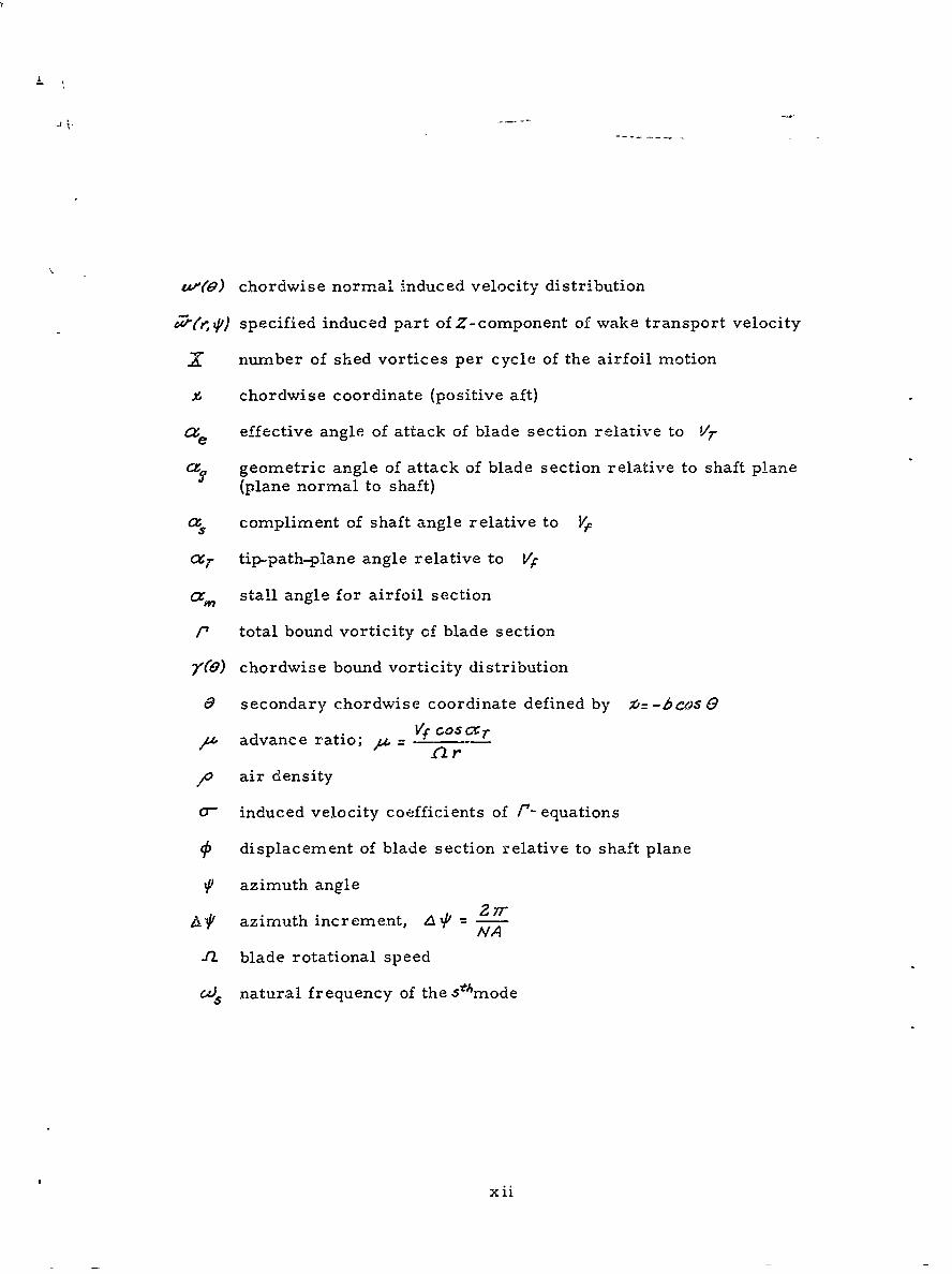
u"c'9) chordwise normal induced velocity distribution
t -i ) specified induced part of Z-component of wake transport velocity
Xnumber of shed vortices per cycle of the airfoil motion
chordwise coordinate (positive aft)
ae effective angle of attack of blade section relative to Vr
cz, geometric angle of attack of blade section relative to shaft plane(plane normal to shaft)
a compliment of shaft angle relative to Vf
cxr tip-path-plane angle relative to VC
Lx, stall angle for airfoil section
/ total bound vorticity of blade section
7"0) chordwise bound vorticity distribution
& secondary chordwise coordinate defined by *=-bcosO
A advance ratio; Az ar--
lo air density
0- induced velocity coefficients of t- equations
Sdisplacement of blade section relative to shaft plane
Uazimuth angle
2~rA? azimuth increment, A%' -IVA
-I blade rotational speed
Cis natural frequency of the .5thmode
xii
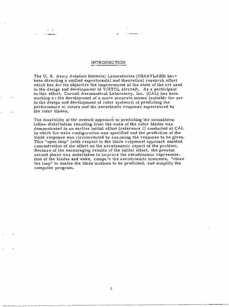
INTRODUCTION
The U. S. Armny Aviation Materiel Laboratories (USAAVLABS) ha-vbeen directing a unified experimental and theoretical research effortwhich has for its objectiVe the improvement of the state of the art usedin the design and development of V/STOL aircraft. As a participantin this effort, Cornell Aeronautical Laboratory, Inc. (CAL) has beenworking o - the development of a more accurate means (suitable for usein the design and development of rotor systems) of predicting theperformance oi rotors and the aeroelastic response experienced bythe rotcr blades.
The feasibility of the overall approach to predicting the nonuniforminflow distribution resulting from the wake of the rotor blades wasdemonstrated in an earlier initial effort (reference 1) conducted at CALin which the wake configuration was specified and the prediction of theblade response was circnmveited by assaming the response to be given,This "open loop" (with respect to the blade response) approach enabledconcentration of the effort on the aerodynamic aspect of the problem.Because of the encouraging results of the initia! effort, the presentsecond phase was undertaken to improve the aerodynamic representa-tion of the blades and wake, compute the aerod.inarnic moments, "closethe loop" to enable the blade motions to be predicted, and simplify thecomputer program.

ASSUMPTIONS
The method developed to predict the aerodynamic loads and dynamicresponse experienced by the blades of a rotor system in steady-statetranslational flight is based on the following principal assumptions:
1. The wake configuration can be adequately prescribed.
Z. The blade slopes in the spanwise direction, and thesection angles of attack below stall are small.
3. The inplare components of the induced velocities at thetip-path plane are small and can be neglected.
4. Below stall, the lift-curve slope is constant.
5. The blade section circulation is limited to a maximumvalue for angles of attack at and above stall.
6. For angles of attack above stall, the blade sectionnormal force is taken as the sum of the stall-limitedcirculatory force and a cross-flow drag force.
7. The Mach number and Reynolds number effects areassumed to influence only the lift-curve slope.
8. The interference effects of the rotor hub, fuselage,etc., are negligible.
The first assumption (that of being able to prescribe adequately the wakeconfiguration) ic believed to be one of the major sources of discrepancybetween he computed and rr easured results. Computations whichindicate the sensitivity of the predicted results to the wake configurationhave been made and will be presented in a latter section of this report.
"Wake configuration" means the time history of the spacial distributionof the vorticity which streams from each blade. In r'eality, L conitinuoussheet of shed and trailing vorticity streams from each blade withstrengths proportional to the time and radial rates of change of thebound vorticity. Under the influence of the forces of viscosity and thethree-dimensional induced velocity field (due to itself and the blade)through which it moves, this vortex wake diffuses, dissipates, anddistorts. The exact configuration of this wake is not completely knownand the state of the art is not sufficiently advanced to permit detailedprediction of this wake configuration. " The tip vortices, however, are
-Thereis some (as yet, unpublished) work proceeding at CAL whichhasdeveloped a method for computing the displacement time history of asystem of segmented concentrated vortices of finite core streamingfrom the rotor blade tips when their strength distribution is specified.
z
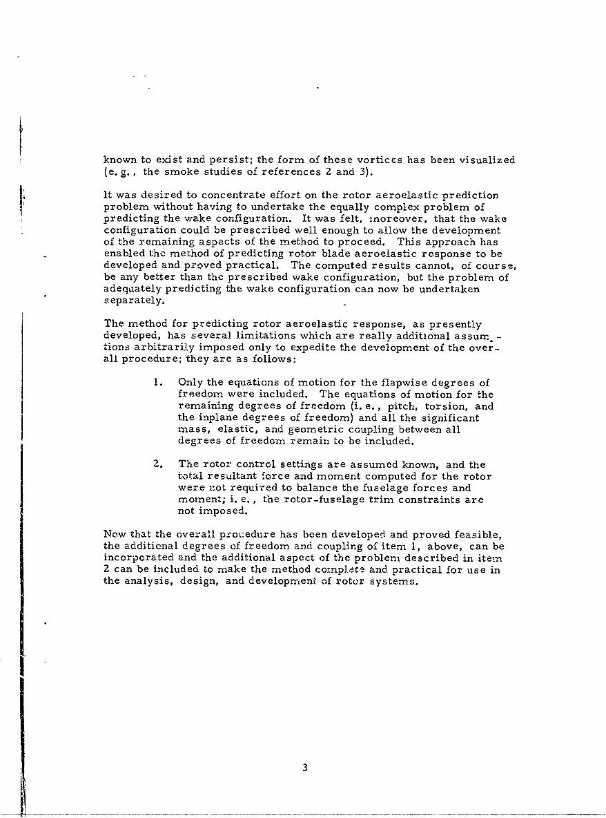
known to exist and persist; the form of these vortices has been visualized(e. g., the smoke studies of references 2 and 3).
it was desired to concentrate effort on the rotor aeroelastic predictionproblem without having to undertake the equally complex problem ofpredicting the wake configuration. It was felt, mnoreover, that the wakeconfiguration could be prescribed well enough to allow the developmentof the remaining aspects of the method to proceed. This approach hasenabled the method of predicting rotor blade aeroelastic response to bedeveloped and proved practical. The computed results cannot, of course,be any better than the prescribed wake configuration, but the problem ofadequately predicting the wake configuration can now be undertakenseparately,
The method for predicting rotor aeroelastic response, as presentlydeveloped, has several limitations which are really additional assur -tions arbitrarily imposed only to expedite the development of the over-all procedure; they are as follows:
1. Only the equations of motion for the flapwise degrees offreedom were included. The equations of motion for theremaining degrees of freedom (i. e., pitch, torsion, andthe inpiane degrees of freedom) and all the significantmass, elastic, and geometric coupling between alldegrees of freedom remain to be included.
2. The rotor control settings are assumed known, and thetotal resultant force and moment computed for the rotorwere not required to balance the fuselage forces andmoment; i. e., the rotor-fuselage trim constraints arenot imposed.
Now that the overall procedure has been developed and proved feasible,the additional degrees of freedom and coupling of item 1, above, can beincorporated and the additional aspect of the problem described in item2 can be included to make the method conpLete and practical for use inthe analysis, design, and development of rotor systems.
3
WAKE REPRESENTATION
As in reference 1, the shed and trailing vorticity distributions in ';hewake of each blade are represented by an arrangement of concentratedstraight-line vortex segments; however, the arrangement of these vortexsegments is now somewhat different than was used previously.
In the present representation, the azimathal extent, bchind each blade,of the grid of straight-line vortex segments representing the shed andtrailing vorticity distributions can be truncated where desired and thewake continued on as segmented root and/or tip trailing vortices. (Thegrid can still be carried fo:: the full extent of the wake, if desired. )The radial positions of the root and/or tip trailing vortices in the wakecan be adjusted to account for the contraction of the wake. This wakerepresentation can better represent the actual wake which, apparently,rolls up very quickly into a tip vortex (see the smoke studies of refer-ences 2 and 3). Figure l(a) illustrates an example of a portion of a wakerepresentation with a root and tip trailing vortex, and Figure l(b) onewith only a tip vortex (for this example, five radial blade segments havebeen used).
In the wake representation of reference i, a segmented shed vortex wasdeposited in the flow at each azimuth position of the blade; thus, thenearest shed vortex to the blade was behind it a distance proportional tothe time it takes the blade to traverse one azimuthal increment. Theadequacy of this representation of the wake shed vorticity was investi-gated by using it in a computational model to predict the lift and pitch-ing-moment transfer functions (for both the pitching and plunging cases)for a two-dimensional oscillating airfoil at zero mean angle of attack.The results were compared with the classical analytical solutions forthis problem and, as was expected, the agreement was not very good. Acomputational investigation of discrete shed wake representations wasthen conducted by use of this computational model for the two-dimensionaloscillating wing problem. It was found that reasonable agreement couldbe obtained in the reduced frequency range of interest by using the equallyspaced discrete shed vortex representation if the entire wake wereadvanced, with respect to the blade producing it, a distance proportionalto 70 percent of a time increment. Thus, on the basis of this result, thewake representation presently used is such that the wake of each bladecan be advanced any desired amount. A description of the two-dimension-al oscillating wing investigation of the discrete shed vortex wake repre-sentation and the results of it are presented in Appendix I.
It should be noted that the two-drnensional unsteady wake effects of thin-airfoil theory arise f- --' the shed vcrticity; whereas, for a three-dimen-sional oscillating wing, "here is an additional source of the unsteady wakeeffects which is the attached trailing..type vorticity. The time-varyingstrength of the trailing vorticity from an oscillating three-dimensionalwing influences the wing in the same, manner as the shed vorticity; i. e.
4
it attenuates and shifts the phase of the lift response to the time-varyingangles of attack just as the shed vorticity. It is believed that the repre-sentation of the trailing vorticity reproduced these unsteady wake effectsquite well.
In reality, the shed and trailing vorticity distributions in the wake stream-ing from each blade are respectively proportional to time and radial ratesof change of the bound vorticity. Therefore, in the wake representationused, the strengths of the shed vortex elements deposited in the wake ateach azimuth position are made equal to the change in strength (betweenazimuth positions) of the corresponding bound vortex elements. Thestrengths of the trailing vortex elements (in the grid portion of the wake)are made equal to the change in strength of adjacent bound vortexelements. Beyond the truncation of the wake grid, the root and/or tiptrailing vortex strengths are made equal to the maximum value of theradial distribution of the bound vorticity on the blade in the azimuthposition from which the elements were shed. The effects of viscousdissipation are neglected and, thus, the strengths of the wake vortexelements do not change with time.
Each wake vortex segment end point is given an individual transportvelocity when it is deposited in the wake; thus, the transport velocitiesof the wake element end points which originate from each point in therotor disk can be different. All wake element end points move withtheir individual velocities only for a specified (in the program input)number of time increments; for the remaining time increments, they allmove with a common velocity. The initial wake element transportvelocity distribution over the disk, the specified number of time incre-ments they move with their individual velocities, and the commonvelocity they all acquire after this specified number of time incrementsare all input parameters. With this means of wake description, it ispossible to (1) have all the wake element end points move with acommon velocity for their entire life (i. e. , an undistorted skewed helicalwake), (2) have all the wake element end points move with individualvelocities for their entire life (i. e., continuously distorted from theskewed helix), or (3) have all the wake element end points move ,:iLhindividual velocities only for a specified length of time and then revertto a common velocity (i. e. , distorted from the skewed helical wake for
a fixed length of time and then maintain that distorted configurationwhile moving away at uniform velocity).
This flexibility of describing the, wake was built in only to allow various.wake configurations to be tried and to determine the sensitivity of theresults to each variation; it does not permit true wake distortions tobe used. In reality, each element of the wake experiences a nonperiodicbut time-varying transport velocity. The actual configurations of thewake streaming from each blade are not completely understood. Forexample, there is some question as to whether the shed vorticity persistslong enough or is in such a configuration that it can significantly influ-ence the following blades. Likewise, does the trailing vorticit, rom
5
the inboard portion of the blades (that vorticity of opposite sense to thatof the tip vorticity) persist and assume a configuration (trailing rootvortex) such that it can have a significant influence on the followingblades ?
The tip vortices and their configurations have been made visible (refer-ences Z and 3). The observed distortions of these tip vortices fromskewed helices are primarily the result of the mutual induced velocitiesbetween successive coils (layers) of the wake. These observed distor-tions are the initial phases of the rolling-up of the helices into two wing-like trailing vortices (i. e., downstream from the disk, the rotor wakeis practically the same as a wing wake). These distortions are influ-enced by the advance ratio, the disk loading, and the number of bladesin the rotor generating the vortices. A skewed stack of equally spacedparallel vortex rings will exhibit the same characteristic distortions.The initial phase of the rolling-up of the tip helices into two wing-liketrailing vortices can best be observed in the downstream views of thcrotor wake made visible in the smoke studies of reference 3.
In order to predict the distortions of these tip vortex helices, it will benecessary to evaluate the total induced velocity at each point on thesevortices at successive increments of time allowing the vortex elementsto move with their respective instantaneous velocities during eachtime increment. For sufficiently small time increments and enoughcollocation points, it should be possible to predict these distortions(i. e., displacement time histories)T
The computation of the wake-induced velocities at the blades is carriedout in a nonrotating tip-path plane oriented (i. e., Xy - plane is parallelto tip-path plane) coordinate system whirh is illustrated in Figure 2.The coordinate system translates with the rotor system at velocity, VFthus, the wake element transport velocities in the X and Z directionsare, respectively, U = Vf cos aT and W= VF sira 40(r,tp) where &(r,z')is a distribution over the rotor disk of the induced part of the Z -comp7n-ent of the wake transport velocity. In this computational procedure, itis this component which makes it possible for each wake element endpoint to have an individual transport velocity. The wake transport in theY -direction is taken to be zero; in reality, the transport in the Y -direc-tion would be due to only the induced velocities in that direction andwould result in a lateral distortion of the wake.
The wake element end points in the wake of a blade are labeled aswhere i denotes the azimuthal distance of the point in the wake behindthe blade and j denotes the radial wake position; this notation is illustratedin Figure l(a). The equations for the X , Y and Z coordinates of thewake points oij are (for > Z)
* See footnote on page 2.
6
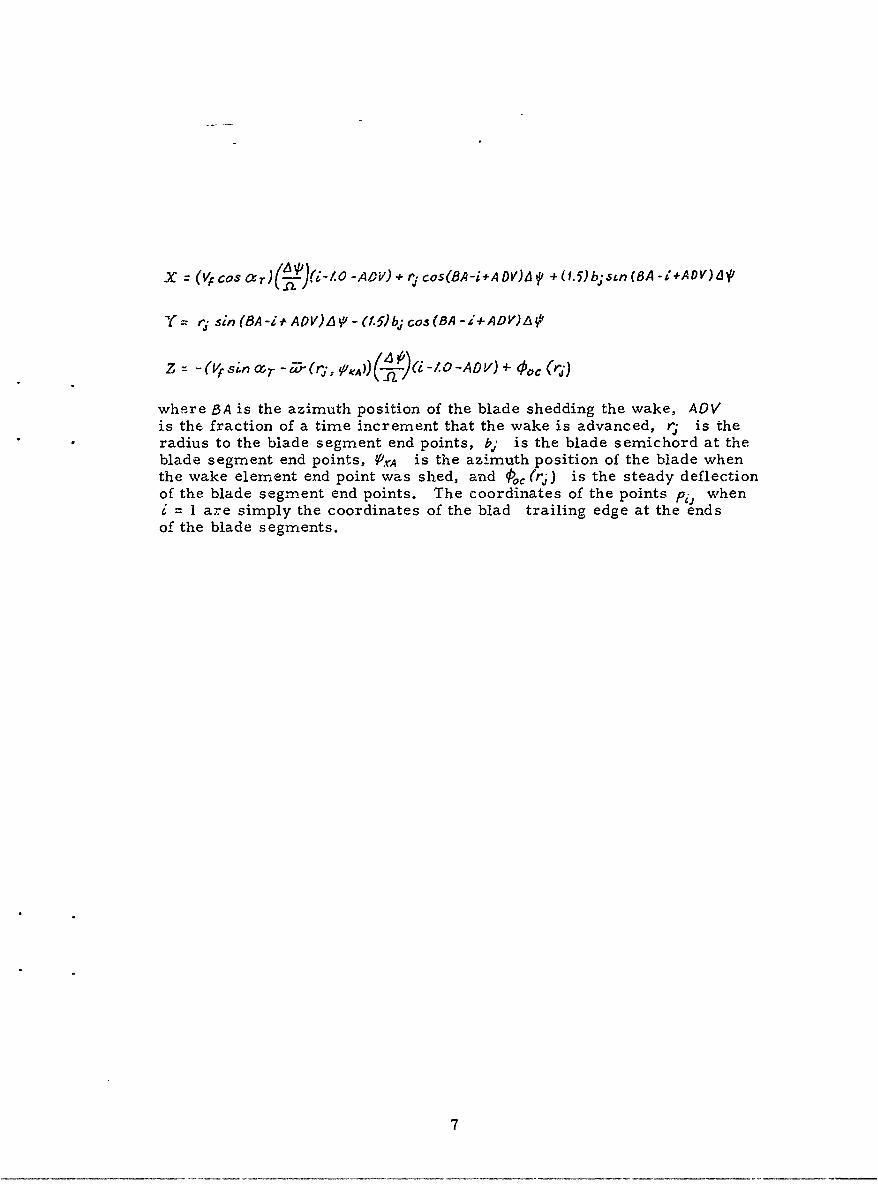
XZ (Vf Cosa c )( !.~)i-/. -AP-W)+*r 1 cos(BA-i+A OV)A $ +( 1.5) bjstn (BA-i +AD V)LW'
"Y= ryj sin (8A-iADV)AV-. (1.5)bj cos(BA -i-ADV)Ai
z V-(r sin -r 1(r, .0)) ( -ZO-AOV) + 00C (rj)
where BA is the azimuth position of the blade shedding the wake, AOVis the fraction of a time increment that the wake is advanced, r is theradius to the blade segment end points, b; is the blade semichord at theblade segment end points, P.rA is the azimuth position of the blade whenthe wake element end point was shed, and qoc (rj) is the steady deflectionof the blade segment end points. The coordinates of the points p- wheni = 1 are simply the coordinates of the blad trailing edge at the ends
of the blade segments.
7
BLADE REPRESENTATION
For the blade representation, the theory of two-dimensional, unsteady,thin airfoils has been used. The blade is divided into VR spanwisesegments, and the chordwise aerodynamic boundary condition is satisfiedat the midsection of each of these segments for the blade in each of MAazimuth positions; thus, there are a total of uRA (-VR xNA) points in therotor disk where the boundary condition is satisfied and the airloadsare computed. The subscript notation for these points over the disk isgiven in Figure 3. The spanwise loading is assumed constant overeach of these blade segments, and it is from the ends of these segmentsthat the trailing vorticity of the wake representation streams withstrength equal to the change in strength of the bound vorticity betweenadjacent segments. The three-dimensional effects due to the inter-action of a spanwise segment with its neighbors has not been .ncluded.Thus, each blade segment is considered to be two-dimensional, andthe three-dimensional effects of the wake are included at each bladeradial station.
The chordwise aerodynamic boundary condition requires that the sumof the velocities normal to the chord be zero (i. e., there can be noflow through the airfoil). The chordwise distribution of these normalvelocities is composed of three parts. The first part is termed thequasi-steady part and is due to orientation of the blade segment relativeto the total local velocity vector, its camber, and its pitching andplunging velocities associated with the blade dynamic response. Thesecond part is termed the wake-induced velocity and is computed fromthe wake vortex representation. The third part, termed the airfoil-induced velocity, is that due to the bound vorticity distribution and isrequired to balance the sum of the first two parlts. That is, it is thebound vorticity distribution which is considered to be the unknown andmust be such as to create an airfoil-induced veio.ity distribution whichjust cancels the sum of the quasi-steady and wake-induced velocities.This sum of the quasi-steady and wake-1iiduced velocities is, thus,termed the impressed velocity distribution because, when it is impressedon the airfoil, a bouud vorticity distribution is called for to createcanceling airfoil-induced velocities.
The coordinate system used for description of the blade representationis shown in Figure 4 where the airfoil chord is centered on the % -axiswith the leading and trailing edges at -b and +b, respectively. Forconvenience in the formulation, a transformation is made to a secondarycoordinate, 0 , by the following transformation:
x=-b cos e (1)
8
Let the chordwise distribution of bound vorticity (i. e. , the chordwisesingularity distribution required to satisfy the boundary condition) on agiven blade radial station, for each instant of time, be expressed in aGlauert series, thusly:
[0,_ A 49sin n . (2)Zfe,~ ~ 17 ()ro n-
The total circulation on the airfoil is given by
Thus,
"=2rrb(Ao +tAf). (3)
The chordwise distribution of the pressure difference is given by thefollowing form of the linearized Bernoulli equation for unsteady flow,
13 p (,t) =p[V, - (Zt) 4. -- fr (-- 7"#,, 3d# j(4)-b
and can be expressed in terms of the Glauert coefficients by substituting(2) into (4), thusly:
A P(0., ) = 2, V, [A0 co Z~ A,, sinnn=f
de2 2 2+ 5 0-0 (-A P,_- + A,+ ),si, noe
The airfoil unsteady lift and pitching moment about the midchord per
unit span can also be expressed in terms of Glauert coefficients bysubstituting (5) into the following e)pressions:
+b
thus,
.X= 2b,[oV, Ao+Af+h -L (A-A 2 ) (6)
I[ 1 1 )
sus i tuti n0 +( 5) -it o t (fio eApr-si o3n (7)
thus 2 VI'5
It should be noted the lift depends only on the flrst three coefficientsof the Glauert series, and pitching moment depends only on the firstfour.
Due to real fluid effects, the bound circulation, lift, and pitchingmoment do not experimentally attain the magnitudes given by equations(3), (6), and (7). An empirical correction factor, Ct /2r , is there-fore applied to the bound circulation and the circulatory part of thelift and moment; the 4'. is the measured lift-curve slope for the air..foil section. The bound circulation, lift, and pitching moment are thus
r C.X h(AO*#Aj) (8)
7= 2 (9)
C, 2 V (Ao A1)+ 7rbpV, (-A, *4 2)
3(10)
The computation of the lift, moment, and Glauert coefficients is in thetime domain and for each radial station the Glauert coefficients areknown only at NA equally spaced discrete azimuth positions. Numericallythe time derivatives indicated in equations (9) and (10) were evaluatedat these discrete points by a procedure which "effectively" fits thepoints with a Fourier series and then takes the slope of this curve.This procedure is presented in Appendix III.
Because the bound vortex strength for each radial segment is periodicand the wake vorticity depends on the radial and time rates 6f changeof the bound vorticity, each of the strengths of the wake vortex elementscan bu expressed in terms of the I/RA bound vortex strengths as indicatedin Figure 5. If the relative orientations of the blade segments and thewake elements are known (or prescribed), application of the Biot-Savartlaw enables the chordwise distribution of induced velocity on a bladesegment at a point, K , in the disk to be expressed in terms of the wakevortex strengths and, thus, in terms of the A/RA strengths of the boundvorticity as
U K~x Z CK1 Wx I" 11
where CK (Z) is the sum of the Biot-Savart coefficients (expressingthe induced velocity distribution over the chord due to a single straight-line element) for all wake elements whose strengths depend on ry .The derivation of the expression for the chordwise-induced velocitydistribution due to a single arbitrarily oriented vortex filament ispresented in Appendix II.
10
For each blade segment and instant of time (i. e. , at each point, K , inthe rotor disk), the expression of the chordwise aerodynamic boundarycondition is given by the following integral equation:
VXC (Z -(Z)-- / b "K d" - , (12),27r z -4
where
and (13)
are, respectively, the quasi-steady and wake-induced parts of thechordwise normal velocity distribution. If the wake-induced part of thenormal velocity distribution (expressed in the 0 -coordinate) is expandedin a Fourier cosine series
&"O) (Sorj * Y 5 cos n (14)
then the impressed velocity distribution which is defined as the sumof the quasi-steady and wake-induced velocities can be writttn as
eK,(') +tUoll(9) -O- +- n "cos n9 (15)nut
where
+ VRA
and $ is the sum of the n t lh harmonic cosine components (of the
'-jR
Biot-Savart coefficients) for each wake element whose strength dependson r" . The derivation of the expressions for the first four cosinecomponents of the chordwise normal induced velocity distribution (i. e.,
So , S, , 3e and $3) due to a single wake vortex filament is presentedin Appendix II.
The result of evaluating the integral of (12), after changing to the 6 -coordinate and substituting (2) for yK(P) is also a cosine series,
7 x(-'-- - A0 , - , A, C 06no. (17)
11
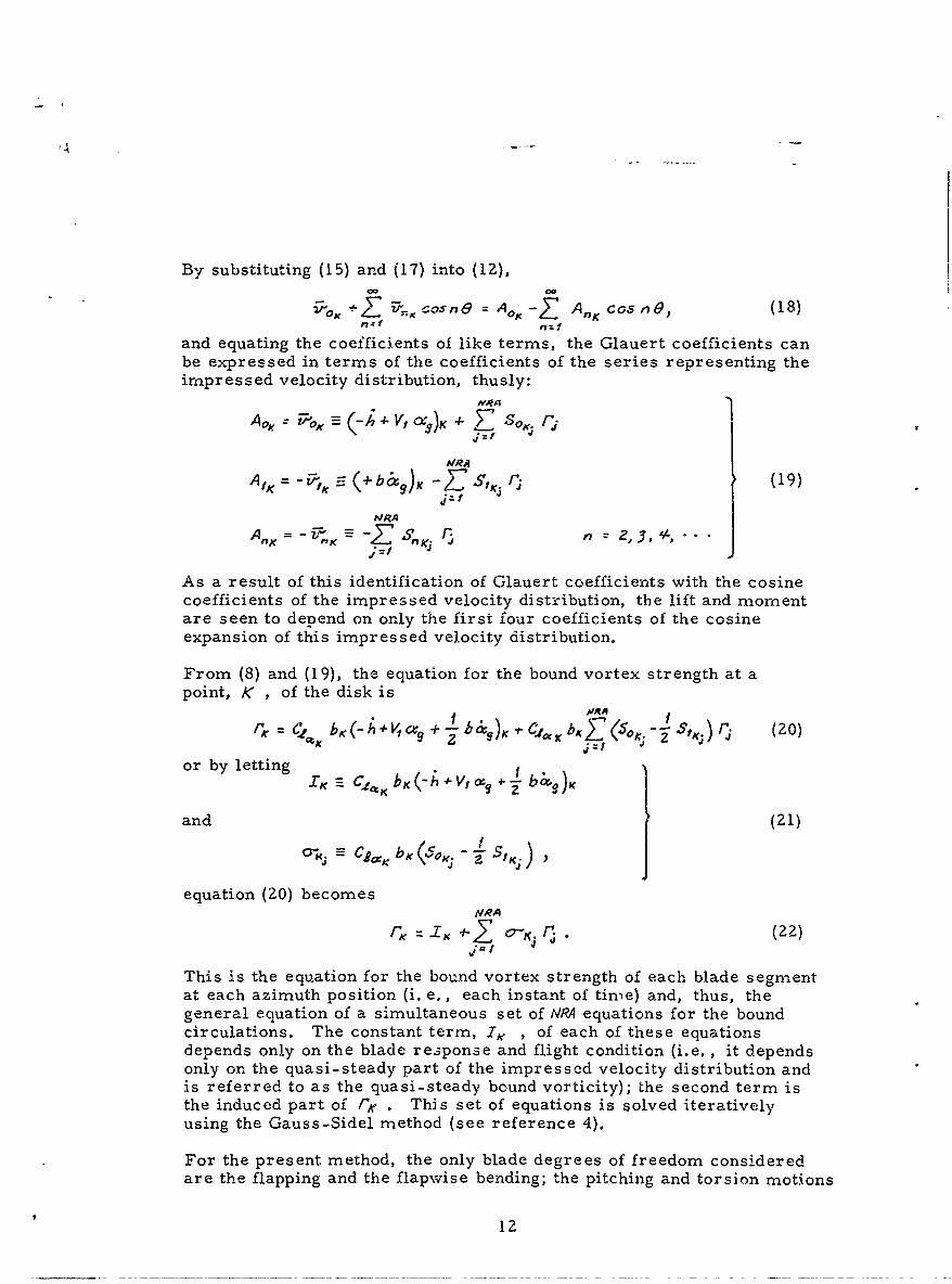
By substituting (15) and (17) into (IZ),00 00
+ Z cos n 0 = A x -,E A, Co0.5n (18)
and equating the coefficients of like terms, the Glauert coefficients canbe expressed in terms of the coefficients of the series representing theimpressed velocity distribution, thusly:
A'R
oo~i~x (-h 4-VI X O )K 4 7 Sof
AIRA
A_ (+b&9 ) S&,q) (19)
NRA
As a result of this identification of Glauert coefficients with the cosinecoefficients of the impressed velocity distribution, the lift and momentare seen to depend on only the first four coefficients of the cosineexpansion of this impressed velocity distribution.
From (8) and (19), the equation for the bound vortex strength at apoint, K , of the disk is
[~~~. C4b(-+, 9 2 b (20)
or by lettingIK C2*K-h + Vtc+b c 9 K
and (21)
equation (20) becomestRAr ZoK (Z (2)
This is the equation for the bound vortex strength of each blade segmentat each azimuth position (i. e,, each instant of time) and, thus, thegeneral equation of a simultaneous set of NR equations for the boundcirculations. The constant term, I.. , of each of these equationsdepends only on the blade response and flight condition (i.e., it dependsonly on the quasi-steady part of the impressed velocity distribution andis referred to as the quasi-steady bound vorticity); the second term isthe induced part of /K . This set of equations is solved iterativelyusing the Gauss-Sidel method (see reference 4).
For the present method, the only blade degrees of freedom consideredare the flapping and the flapwise bending; the pitching and torsion motions
12
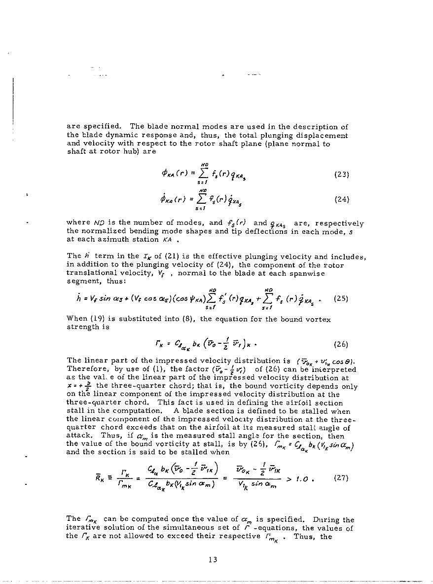
are specified. The blade normal modes are used in the description ofthe blade dynamic response and, thus, the total plunging displacementand velocity with respect to the rotor shaft plane (plane normal toshaft at rotor hub) are
NO
~KAZr/ (24)s:I
where ND is the number of modes, and f 5 (r) and ?KA, are, respectivelythe normalized bending mode shapes and tip deflections in each mode, sat each azimuth station <A .
The i term in the Z of (21) is the effective plunging velocity and includes,in addition to the plunging velocity of (24), the comnonent of the rotortranslational velocity, V; , normal to the blade at each spanwisesegment, thus:
W40 4DO
/ Vp sin a5 + (Vp cosS.) (Cos PKA4),E <PS *2j7.P (r) KA5' (25)
When (19) is substituted into (8), the equation for the bound vortexstrength is
r.' 0, 4; Kb. K(26)
The linear part of the impressed velocity distribution is (U;K + V,, cos&).
Therefore, by use of (1), the factor (r- z,-,) of (26) can be interpretedas the val. e of the linear part of the impressed velocity distribution atx = + A the three-quarter chord; that is, the bound vorticity depends only
2on the linear component of the impressed velocity distribution at thethree-quarter chord. This fact is used in defiaing the airfoil sectionstall in the computation. A blade section is defined to be stalled whenthe linear component of the impressed velocity distribution at the three-quarter chord exceeds that on the airfoil at its measured stall aiigle ofattack. Thus, if a, is the measured stall angle for the section, thenthe value of the bound vorticity at stall, is by (26), / = C/a bAand the section is said to be stalled when K
C- ,. F__1 K -- IR K _9_ > /. _(Z7)
r,- CPj bK(V .SinO'a,) V, Seno, > 10. 27MK KA
The /r"K can be computed once the value of a, is specified. During theiterative solution of the simultaneous set of r -equations, the values ofthe I'K are not allowed to exceed their respective f " Thus, the
13
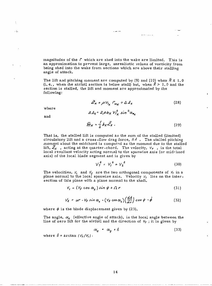
magnitudes of the r which are shed into the wake are limited. This isan approximation to prevent large, unrealistic values of vorticity frombeing shed into the wake from sections which are above their stallingangle of attack.
The lift and pitching moment are computed by (9) and (10) when R : 1.0(i. e., when the airfoil section is below stall) but, when q > 1. 0 and thesection is stalled, the lift and moment are approximated by thefollowing:
Kt"K
whereand /JA , = 2,4ohK VrK Sin ac
and °i Ab e i ~
2? 2 (29)
That is, the stalled lift is computed as the sum of the stalled (limited)circulatory lift and a cross-flow drag force, 6-1 . The stalled pitchingmoment about the midchord is computed as the moment due to the stalledlift, 4,< , acting at the quarter-chord. The velocity, Vr , is the totallocal resultant velocity acting normal to the spanwise axis (or midchordaxis) of the local blade segment and is given by
VT= V, V2 (30)
The velocities, V, and V2 are the two orthogonal components of Vr in aplane normal to the local spanwise axis. Velocity V1 lies on the inter-section of this plane with a plane normal to the shaft.
V, = (V cos a., ) sin - r (31)
V2 C0 (32)
where 0 is the blade displacement given by (23).
The angle, a. (effective angle of attack), is the local angle between theline of zero lift for the airfoil and the direction of Vr ; it is given by
+ (33)
where & = arctan (V2 /V,).
14
COMPUTATIONAL PROCEDURE
The computational procedure is fundamentally an iterative procedurewhich repetitively computes the aerodynamic loads and solves the equa-tions of motion of the blade so as to obtain consistent airloads and bladeresponse. The resulting solution includes all the aerodynamic couplingbetween the degrees of freedom.
The computational procedure requires that the wake configuration bespecified; that is, that the relative orientation of the blade segmentsand the wake vortex elements be known. To establish this relativeoiientation, the first-order displacements of the blades relative to theshaft are needed. Thus, in addition to the rotor translational velocity,shaft angle, and wake transport velocities, a reasonable approximationof the steady-state displacement of the blade relative to the shaft (i. e.,coning and/or steady bending), and the first harmonic cosine flappingangle are needed to establish the relative orientation of the bladesegments and wake elements. If the steady blade displacement andfirst cosine harmonic flapping (relative to the rotor shaft) predictedby the method are significantly different from the estimates used toestablish the relative orientation of the blades and wake, the computedvalues should be used to re-establish the wake orientation and then thecomputation repeated.
First, the blade and wake coordinates are computed, and then anintegration (summation) over the wake is perforred to obtain the matricesof induced velocity coefficients Sk through 5. as defined in equation(14). These coefficients are for the wake-induced velocities normal tothe tip-path-plane, but are computed at the steady-state deflectedpositions of the blades. Because the blade spanwse slopes are small,these induced velocities are assumed to act in the direction of V2 [equation(32)]. From these induced velocity coefficients, the matrix of coeffi-cients, cj , for the simultaneous set of bound vortex equations ( r -
equations) is computed.
Next, an iterative procedure is used to solve the equations for the aero-dynamic loads and blade response. (A flow diagram indicating the mainconceptual elements of this iterative procedure is presented in Figure 6.)The procedure begins with a first approximation to the blade responseand then evaluates the constants, I , [given by equation (21)] of the /'-equations. The /' - equations are next solved iteratively by use of theCauss-Sidel method and then the Glauert coefficients evaluated byequation (19). From the Glauert coefficients, the lift ana pitchingmoments are computed, and then a "generalized airload" is computed ineach mode for each azimuth position by integrating the product of modeshape and the spanwise airload over the span. The generalized airloadin each mode is then harmonically analyzed and used as the forcingfunction for that mode at each harmonic. The blade equations of motionfor each mode are then solved for the response at each harmonic. With
15
this new approximation to the blade response, the I's of the F - equa-tions are recomputed and the entire computational process is repeated.This process is repeated until the blade response converges to withinprescribed limits.
The generalized airload is not the forcing function as conventionallydefined because it contains, in addition to the aerodynamic forces inde-pendent of the response, all the aerodynamic loads which are directlyand indirectly a result of the blade response. These additional loads arethe aerodynamic spring, damping and mass forces, and the aerodynamiccoupling force from the wake. Normally, terms representing these aero-dynamic forces that are proportional to the system reponse are put onthe left side of the equation of motion along with the other terms whichare also proportional to the system response. The forces that areindependent of the system response are put on the right side of the equa-tion. In the computational procedure which has been developed, theseresponse-dependent components of the airload are implicit in the solutionof the F- equations and the computation of the resultant airloads. There-fore, by using the generalized airload as the forcing function, theresponse-dependent airloads are effectively taken from the left side of theequation and included with the conventional forcing function on the right.This, of course, does not alter the equation of motion nor its solution.in the computational procedure described above, the generalized airload(right side of equation of motions) is evaluated for the existing approxi-mation to the response (from previous iteration). By using this as theforcing funct on, the equation of motion is then solved for the nextapproximation to the response. Unfortunately, when this process isrepeated it will not always converge.
An investigation was made to determine and understand the controllingfactors of this iterative procedure. It was found that convergence of thisprocedure was improved when the dependence of the right side of theequation on the variables (i. e., on the response) was reduced. This isevident when the right side is, in fact, independent of the variables, thenthe result of the first iteration is the solution. Thus, in the computationalprocedure which has been developed, the dependence of the right side(i. e., the generalized airloads) on the response is reduced by subtractingan approximation for the quasi-steady damping from both sides of theequation. That is, a term which is believed to be the largest response-dependent part of the airload has effectively been brought back to the leftside of the equation from the right side. This quasi-steady dampingsubtracted from the right side is computed as a function of the responseof the previous iteration, while that subtracted from the left is computedas a function of the response of the present iteration. When the solutionconverges, these two are equal and the equation is unaltered. Thisprocedure has worked very well, thus far, and the solution obtained isindependent of this approximate quasi-steady damping correction terni,but the rate of convergence does depend on it. It was found that bothhalving and doubling this term increased the number of iterations requiredfor convergence without changing the solution.
16
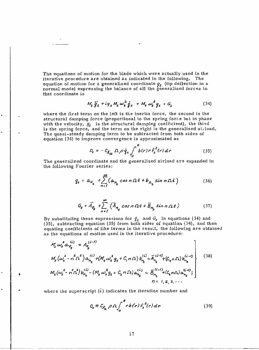
The equations of motion for the blade which were actually used in the,iterative procedure are obtained as indicated in the following. Theequation of motion for a generalized coordinate F. (tip deflection in anormal mode) expressing the balance of all the generalized forces inthat coordinate is
K4~s~i.s5swzs MZ ~'(34)
where the first term on the left is the inertia force, the second is thestructural damping force (proportional to the spring force but in phasewith the velocity, g, is the structural damping coefficient), the thirdis the spring force, and the term on the right is the generalized ai-:load.The quasi-steady damping term to be subtracted from both sides ofequation (34) to improve convergence is approximated as
R
DI C ao (r r P (r)d r(35)0
The generalized coordinate and the generalized airload are expanded inthe following Fourier series:
Sa.0 i-( , cosnn +b Ssin li) (36)
(35), subtracting equation (35) from both side!F of equation (34), and thenequating coefficients of like terms in the result, the following are obtainedas the equations of motion used in the iterative procedure:
2 a,() A(-)
Z( f ) W ,- U-1 (38)- f+ A,,, a-(C,nn.)b,,
(60 "l S 17S - ns +(CS b,° "2 )b(i) Z (Z) -1) (
S rn)- (MW . t C n a,,, ,s + .fl: 1,2,3,-
where the superscript (i) indicates the iteration number and
,oa rh(r) (r) (39)
17
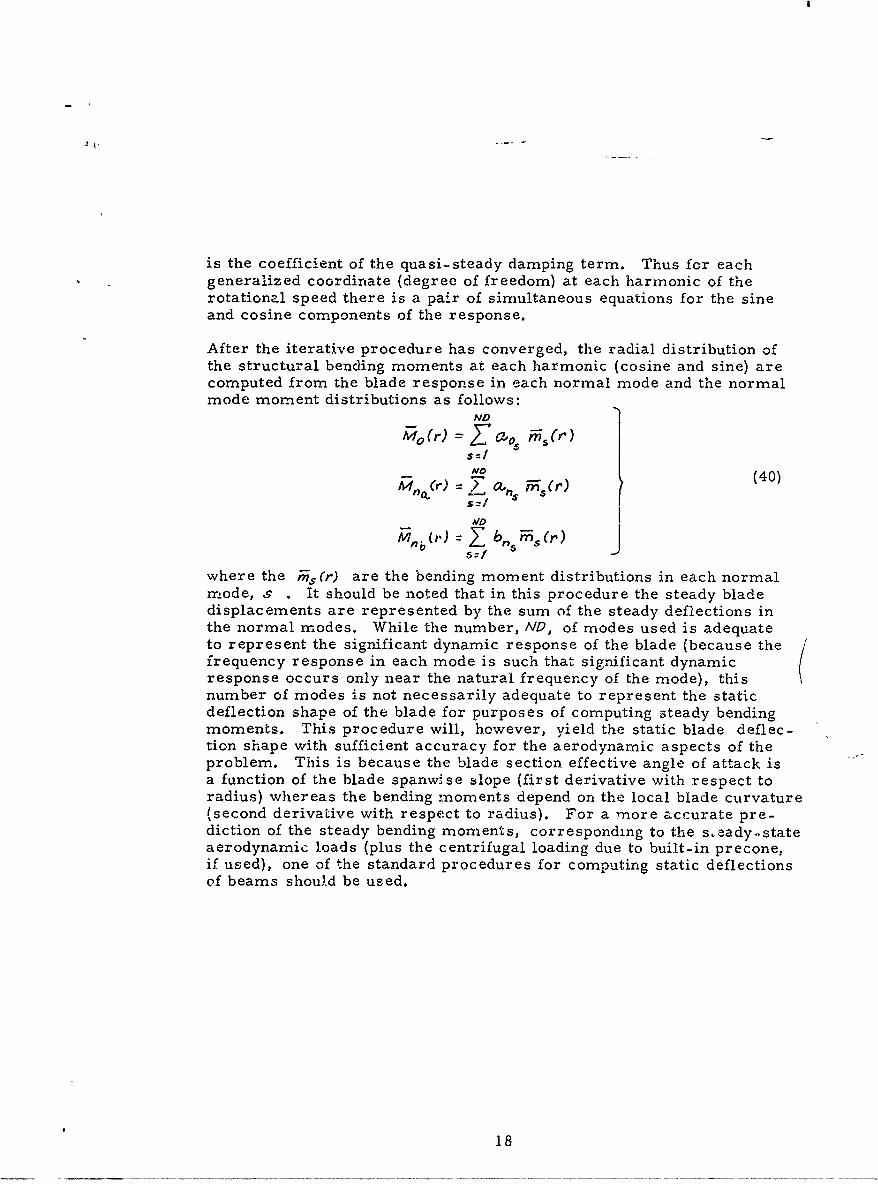
is the coefficient of the quasi-steady damping term. Thus for eachgeneralized coordinate (degree of freedom) at each harmonic of therotational speed there is a pair of simultaneous equations for the sineand cosine components of the response.
After the iterative procedure has converged, the radial distribution ofthe structural bending moments at each harmonic (cosine and sine) arecomputed from the blade response in each normal mode and the normalmode moment distributions as follows:
ND
No
Al, (r)=?a, ir) (40)
S=
AID
5=1
where the ; (r) are the bending moment distributions in each normalmode, s . It should be noted that in this procedure the steady bladedisplacements are represented by the sum of the steady deflections inthe normal modes. While the number, AID, of modes used is adequateto represent the significant dynamic response of the blade (because thefrequency response in each mode is such that significant dynamicresponse occurs only near the natural frequency of the mode), thisnumber of modes is not necessarily adequate to represent the staticdeflection shape of the blade for purposes of computing steady bendingmoments. This procedure will, however, yield the static blade deflec-tion shape with sufficient accuracy for the aerodynamic aspects of theproblem. This is because the blade section effective angle of attack isa function of the blade spanwise slope (first derivative with respect toradius) whereas the bending moments depend on the local blade curvature(second derivative with respect to radius). For a more accurate pre-diction of the steady bending moments, corresponding to the s-eady-stateaerodynamic loads (plus the centrifugal loading due to built-in precone,if used), one of the standard procedures for computing static deflectionsof beams should be used.
18
COMPUTER PROGRAM
The computer program is written entirely in Fortran IV for the IBM7044 EDP, and is physically two separate programs (Part I and Part 2)which are run sequentially. Each part required essentially the entireavailable core storage capacity. The program required two tape drivesin addition to the three for the monitor system input, output, and libraryfiles. Each of these two parts is subdivided into subroutines for easeand convenience of programming, check out, and the incorporation ofmodifications. The running time for the complete program depends onthe individual problem being processed (i. e., on the number of blades,blade segments, azimuth positions, the wake configuration used, thenumber of revolutions of wake, the number of degrees of freedom used,and the number of iterations required to obtain the solution). For thecomputations which have thus far been made, Part 1 of the program hasrequired from 0. 10 to 0. 20 hour and Part 2 has required from 0. 15 to0. 25 hour of machine time.
Part 1 of the program generates the blade segment and wake elementcoordinates, and then it evaluates the matrices of induced velocitycoefficients by integrating the Biot-Savart expression over the wake -these are stored on tape. Part 2 of the program evaluates the coeffi-cients for the r -equations and the equations of motion; then it solvesthe system of equations by the iterative procedure. After the solutionhas converged, the time histories of all the results are harmonicallyanalyzed and both the time histories and their Fourier coefficients areprinted as outputs together with all the inputs for both parts of theprogram. Flow diagrams indicating the logic for both parts of theprogram are presented in Appendix IV.
19
COMPUTED RESULTS AND COMPARISONSWITH MEASURED RESULTS
The computational procedure was used to analyze two flight conditions ofeach of two rotor systems for which measured airloads and blade bend-ing moments are available. These four computations are for the HU-1Arotor at advance ratios of 0. 08 and 0. Z6, and for the H-34 rotor atadvance ratios of 0. 18 and 0. 29. Comparisons of the measured andcomputed lift loads and blade-flapwise bending moments are presented;however, only the computed pitching moments are presented becausemeasurements of them are not available.
The dynamic response of a rotor blade can be expressed in terms of itsresponse in each of its normal modes. The response in each normalmode at each harmonic of the rotational speed is proportional to both theamplification factor and the generalized force for the specific mode andharmonic. The amplification factor is determined by the ratio of theharmonic forcing frequency to the natural frequency (of the mode underconsideration), and the generalized force is determined by the modeshape and radial distribution of the airload at the specific harmonic.Therefore, to predict accurately the bending moments at each harmonic(and, thus, the total bending moments), it is necessary to know thenatural frequencies and to predict the radial distribution of the airloadat each harmonic accurately; it is not sufficient to simply predict timehistories of the airload which look similar (that is, agree approximatelyin the lower harmonics) to the measured airloads at a few radial stations.Because of the importance of the harmonic components of the airload,their radial distributions are presented here, in the comparisons of themeasured and computed results, in addition to the time histories of thetotal airload. Furthermore, presentation of the harmonics is a muchmore detailed view of the airload distribution (over the rotor disk)because it displays its constituents and can thus provide a much morecritical comparison. Both forms of presentation are also used for thebending moments.
In addition to the computations made for comparison with the measuredresults, a computational investigation was made to determine therelative sensitivity to some of the input wake configuration parameters.It was found that the sensitivities depend on the particular application.The only general conclusion which can be drawn is that the wake configur-ation is important and a better means for establishing it more accuratelyis needed. Results of this investigation are presented later.
All the input information required for the computations, as well as themeasured results used for the comparisons, was obtained from refer-ences 5 and 6. The bending normal mode shapes, moment distributions,and natural frequencies were computed from the blade mass and elasticdistributions contained in these references. All the computations forboth rotor systems were made for 24 blade azimuth positions. For the
20
computations, the HU-IA blade was divided into 8 spanwise segmentsand the H-34 into 9 spanwise segments as shown in Figure 7. Themidpoints of these segments include all the radial stations for whichmeasured airloads are available. In all the computations presented forcomparison with measured results, the first three azimuthal segmentsof wake behind each blade were of the grid representation and the remain-der of the wake was only a tip vortex positioned at 90 percent (represent-ative contraction observed in reference 2) of the blade radius. Thenumber of revolutions of wake varied for each case depending on theadvance ratio. Unless otherwise noted, the computed momentum inducedvelocity is used for the induced part, r(r, VI) , of the Z -component ofwake transport velocity.
The steady components (mean value) have been subtracted from the time.-history presentations in the comparisons of computed and measuredresults, and the radial distribution of these components is presentedwith the other harmonic components.
21
\I
HU-lA at/z 1.0.26
To establish the wake configuration for this case, the following are the
values of the parameters used:
Vf = 188.0 feet per second
aT = 5. 8 degrees
(r, )= -6.0 feet per second
NW = 2 (Number of revolutions of wake)
A9V = 0. 7 (wake advance)
The measured and compuied time histories and radial distributions of theharmonics of the lift loadings and the blade-flapwise bending momentsare presented in Figure 8. From the time histories, it appears thatthere is reasonable correlation between the measured and computedresults. The correlation does not, however, appear as good when theradial distribution of the harmonics is compared. In general, thecorrelation for the airloads is best for the lower harmonics. The radialdistributions of the higher harmonics of the airlead are not as wellpredicted as their relative amplitudes. This is true at most harmonicsof the bending moments. It is noted that above the 5th harmonic themeasured and computed bending moments are insignificant.
The reversal, at the inboard end of the blade, in the radial distributionof the measured steady-bending moment is due to the centri.agal forcemoments (arising from the built-in preconing of the blades) exceeding thelift moments at the inboard end of the blade. Because the steadycomponent of the lift losding is overpredicted, the lift moment exceedsthese centrifugal moments at the inboard end of the blade and the reversaldoes not occur in the computed steady-bending moment.
In the time history of the airloads, it was observed that the computedairloads are slightly advanced with respect to the measured airloads onthe advancing side of the disk and retarded on the retreating side. Thiseffect would, result if the wake configuration, used in the computation,was skewed slightly more than the actual wake. Thus, a blade wouldsee the wake of the preceding blade sooner on the advancing side andlater on the retreating side. This small difference could arise becauseof an error in the advance ratio or because of induced velocities in theX-direction (which have been neglected), increasing the transportvelocity in that direction.
22
HU-IA at /L = 00 08
The wake configuration for this case was established by the followingvalues of the parameters:
V., = 55. 1 feet per second
aZ7 = 2. 5 degrees
('r, )= -21.0 feet per second
'= 6 (revolutions of wake)
API = 0.7 (wake advance)
The time histories and radial distribution of the harmonics of the air-loading and blade-flapwise bending moments are presented in Figure 9.The correlation here is not as good as that obtained at /z = 0. 26. Themean value of the airloading has been underpredicted and likewise thehigher harmonics of the airloading have been underpredicted. Thediscrepancies are attributed primarily to the wake configuration's beinga poor representation of the real wake for this case. The abruptchanges in the airload on both the advancing and retreating sides of thedisk (which are due to the indu.ced velocity variation) are not well pre-dicted for this case.
The various contributions to the conputed lift loading at r1R = 0. 95 arepresented in Figure 10. Here in Figure 10a are presented, for thisradial station, the quasi-steady bound vorticity, I , and the totalbound vorticity, F , together with the lift loading ." • The inducedvelocity (which is directly proportional to the difference between /' andthe quasi-steady bound vorticity) is presented in Figure l0b. It isobserved here that the induced velocity is most negative over the rearhalf of the disk and is nearly zero or positive over the forward half ofdisk. This is characteristic of the induced velocity distributions oftranslating rotors because (as observed in Figure 21) the blade stationsare generally on the downwash side of the preceding blade tip vorticesas the blade goes from V1 = 270 degrees to V = 90 degrees (rear half ofdisk) and on the upwash side of them as the blade goes from W = 90degrees to V' = 270 degress (forward half of disk). It is also observedthat, while the induced velocity incurs a large total change as the bladepasses from the rear half of the disk to the forward half of the disk, itdoes not change as abruptly zs would be expected (nor as is observed inFigure 13b, for the H-34 at fz = 0. 18). The real wake (tip vortex) isprobably much closer to the rotor disk on the advancing and retreatingsides of the disk because of the Z - component of the distortion of the tipvortex due to its rolling up on itself at the sides of the wake as describedin the section on the wake representation. Also, corresponding distor-tions in the X and Y - directions could make the approach of the bladeto the preceding blade's tip vortex more abrupt (i. e., the angle between
23
this vortex and the blade would be small) as viewed in X-y plane ratherthan very gradual as was the case for this computation (where the angleis nearly 90 degrees). The reversal in the distribution of the steady-bendirg moment, Figure 9d, and negative value near the blade root areoverpredicted for this case bec-use the steady component of lift wasunderpredicted and thus the negative moments due to the centrifugalloading arising from the preconing are predominant. The overall correl-ation of the harmonics of the bending moments appears to be fairly goodcompared to the correlation of the airloads. This is because the higherharmonics of the bending moments are negligible, and it is the higherharmonics of the airload which are not well predicted. The correlationof the lower harmonics of the airload is reasonable and so also are thesignificant lower harmonics of the bending moments.
H-34 at /z = 0. 29
The following parameter values were used to establish the wake con.igur.-ation for this case:
vf = 189. 2 feet per second
a = 6.0 degrees
(r,€,) = -6.4 feet per second
W = 2 (revolutions of wake)
The comparisons of the measured and computed time histories andharmonic distributions of the airloads and bending moments are pre-sented in Figure 11. Because of errors in the measured steady compon-ent (zeroth harmonic) of the bending moments, they are not presented inFigure lld. The time histories of the airload appear to correlatereasonably well. However, the harmonic distributions indicate that thecorrelation is primarily at the lower harmonics, while the higherharmonics are generally overpredicted. it is interesting to note thatthe relative correlation of the first harmonic cosine component of thelift is very similar to that obtained for the HU-1A at /. = 0. 26, and thatthe first and second harmonic components of the lift for these twocases are also similar.
It is evident from the time histories of the bending moments, that onlythe low harmonics correlate, and this is confirmed in the harmonicdistributions. The higher harmonics are generally overpredicted. Thisis especially true for the eighth harmonic and is due to the third bendingmode natural frequency being near the eighth harmonic of the rotationalspeed.
24
H-34 at ,,, = 0. 18
Pot this case, the wake configuration was established by the followingvalues of the wake parameters:
Vf = 118. 2 feet per second
Cr = 3. 3 degrees
(r, Vj= -10. 6 feet per second
NW = 3 (revolutions of wake)
ADV = 0.7 (wake advance)
The time histories and the radial distribution of harmonics of the liftloading and bending moments are presented in Figure 12. The correl-ation in both the time histories and the harmonics of the airloads for thiscase is, in general, better than for the other cases. The abrupt riseand fall of the airloads on the advancing and retreating side of the disk,Figure 12a, have apparently been slightly overpredicted here, whereasfor 'he low advance ratio case for the HU-IA they were underpredicted.It is also noted that the computed airloads are slightly advanced withrespect to the measured airloads on the advancing side of the disk andslightly retarded on the retreating side as was noted for the HU-IA at/. = 0. 26. This seems to be generally true for most of the computations.Here again the harmonic distributions portray the discrepancies betweenthe measured and c- -nputed airloads while the time histories appearto correlate reasonably well. The computeQ radial distributions of thesteady and first harmonic components compare quite well with thosemeasured. The computed radial distributions of the "econd and higherharmonics contain relatively large radial variations. Similar varia-tions are evident in the second and third measured -zomponents but witha small amplitude.
Because of errors in the measured ,teady component (zeroth harmonic)of the bending moments, they are not presented in Figure 12d. Theoscillatory moments correlate reasonably well, except for the higherharmonic response, due primarily to the third bending mode.
An interesting insight into the genesis of the airloading can be obtainedfrom Figure 13, where for r/R = 0. 95, the quasi-steady component, Iof the bound vorticity, the total bound vorticity, P' , the airloading, ,and the wake-induced velocity time histories are presented. It shouldbe remembered that the difference between the I and P" curves is theinduced part of the bound vorticity which is proportional to the wake-induced velocity. First, it is noted for this case that the decreasingairload as the blade goes from V/ = 0 to V = 60 degrees is not due to theblade encountering abruptly the downwash of a trailing vortex, but isdue to the rapidly decreasing quasi-steady component of P (i. e., due
Z5
to the blade velocity, motions, and pitch inputs). The sharp rise inthe airload as the blade goes from t= 300 degrees to W4 = 330 degreesis similarly due to I . The sharp decrease from 'I = 75 degrees to
= 120 degrees and the rise from tP = 240 to V = 290 degrees arepartially due to the wake-induced velocity variation, but predominatelythe result of the I variation. The sharp rise on the advancing side,and drop on the retreating side, is due only to the wake-induced velocityvariation. Thus, it is seen that the character of the airloads is stronglyinfluenced by the quasi-steady aspect of the problem. The wake-inducedvelocity variations are characteristically "hat shaped", as in Figures10b and 13b.
In the past, there has been speculation that the lift variation on theadvancing and retreating sides of the disk (which resembles the"characteristic" induced velocity variation of a single vortex) was areflection of the induced velocity field of the tip vortex of the precedingblade. From the above discussion, it is evident that this is not necessar-ily true. For this case, the lift variation (which has this characteristic)is the result of both the wake-induced and quasi-steady velocities andnot primarily the reflection of only the induced velocity experienced bythe blade section.
Pitching Moments
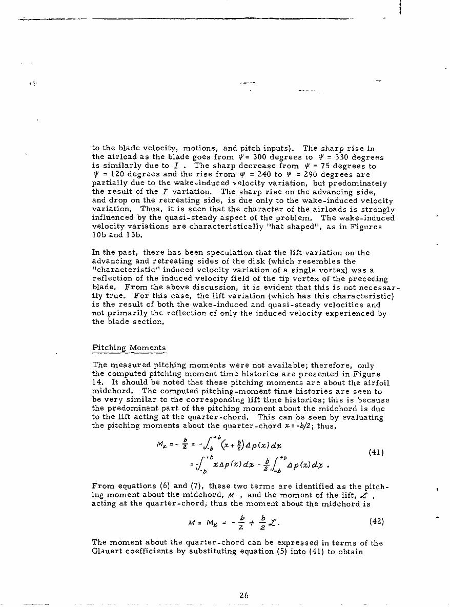
The measured pitching moments were not available; therefore, onlythe computed pitching moment time histories are presented in Figure14. It should be noted that these pitching moments are about the airfoilmidchord. The computed pitching-moment time histories are seen tobe very similar to the corresponding lift time histories; this is becausethe predominant part of the pitching moment about the midchord is dueto the lift acting at the quarter-chord. This can be seen by evaluatingthe pitching moments about the quarter-chord X=-b/2; thus,
f b b (41)
= xAp(x)dz -- h~ A p W ly,- ~~i-b - b
From equations (6) and (7), these two terms are identified as the pitch-ing moment about the midchord, M , and the moment of the lift, e ,acting at the quarter-chord; thus the moment about the midchord is
my, -~ ± b C (42)Z 2
The moment about the quarter-chord can be expressed in terms of theGlauert coefficients by substituting equation (5) into (41) to obtain
26
re
bb 72 A -!tA7r- -Z A
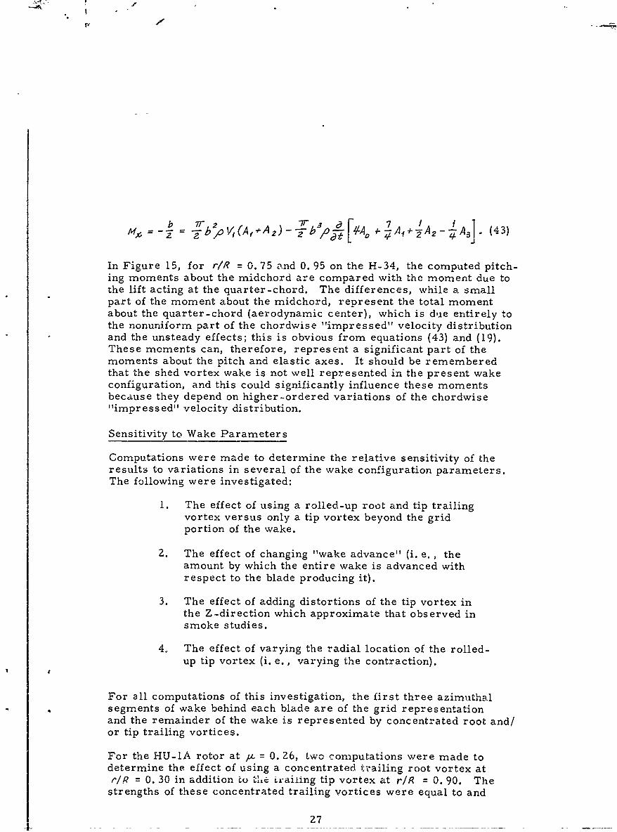
o V =(A,2) - - o A- 2 -A3 (43)
In Figure 15, for r/R = 0.75 and 0. 95 on the H-34, the computed pitch-ing moments about the midchord are compared with the moment due tothe lift acting at the quarter-chord. The differences, while a smallpart of the moment about the midchord, represent the total momentabout the quarter-chord (aerodynamic center), which is due entirely tothe nonuniform part of the chordwise "impressed" velocity distributionand the unsteady effects; this is obvious from equations (43) and (19).These moments can, therefore, represent a significant part of themoments about the pitch and elastic axes. It should be rememberedthat the shed vortex wake is not well represented in the present wakeconfiguration, and this could significantly influence these momentsbecause they depend on higher-ordered variations of the chordwise"impressed" velocity distribution.
Sensitivity to Wake Parameters
Computations were made to determine the relative sensitivity of theresults to variations in several of the wake configuration parameters.The following were investigated:
I. The effect of using a rolled-up root and tip trailingvortex versus only a tip vortex beyond the gridportion of the wake.
2. The effect of changing "wake advance" (i. e., theamount by which the entire wake is advanced withrespect to the blade producing it).
3. The effect of adding distortions of the tip vortex inthe Z-direction which approximate that observed insmoke studies.
4. The effect of varying the radial location of the rolled-up tip vortex (i. e., varying the contraction).
For all computations of this investigation, the first three azimuthalsegments of wake behind each blade are of the grid representationand the remainder of the wake is represented by concentrated root and/or tip trailing vortices.
For the HU-IA rotor at / = 0. 26, Lwo computations were made todetermine the effect of using a concentrated trailing root vortex atr/R = 0. 30 in addition to t.e irailing tip vortex at rIR = 0. 90. Thestrengths of these concentrated trailing vortices were equal to and
27
I
varied azimuthally as the maximum value of the radial distribution ofthe blade bound vorticity. It was found that adding the concentratedroot vortex of strength equal to the tip vortex had a relatively smalleffect on the airloading and the bending moments. This is evident inFigure 16 where the time histories of the airloading at r/R = 0. 95 andthe bending moments at r/R =.0. 21 are presented. Thus, for thisrotor and flight condition, the root vortex had very little effect on thecomputed results.
The effect of wake advance was investigated using i.,x g-U-lA rotor atk = 0. 26 where the wake advance was changed from 0. 0 to 0. 7. This
had a relatively small effect, but, in general, increasing the wakeadvance attenuated and shifted the phase of the airloads, blade response,and bending moments at the higher harmonics. This attenuation wasrelatively large for the response in the blade modes near resonance.For example, the first antisymmetric blade response at the thirdharmonic decreased 30 percent, and the second antisymmetric responseat the fifth harmonic decreased 38 percent. The attenuation in thehigher harmonics of the lift variation is as expected because increasingthe wake advance increases the effectiveness of the shed vorticitywhich attenuates and shifts the phase of the lift variations.
The effect of distorting the wake in the Z -direction was investigated byintroducing distortions, of the form reported in references 2 and 7,into the wake of the HU-IA rotor at a = 0. 08. This distortion of thetip vortex is the initial phase of the rolling up of these (initially helical)vortices into two wing-like trailing vortices and is primarily influencedby the advance ratio, the disk loading, and the number of blades in therotor. The rotor used to visualize these distortions and the HU-IArotor are both two-bladed. The form of the distortion used is taken,therefore, from results at comparable advance ratios in reference 7and scaled according to the relative disk loadings for the two rotors.It was hoped that this would introduce distortions of at least the properform and indicate their effect relative to the regular skewed helicalwake.
The distortion of the wake used is shown in Figure 17, where the tipvortices on the retreating side of the rotor disk are presented. Thecomputed airloads at rIR = 0. 95 obtained with and without the abovewake distortion are presented in Figure 18. The largest effect on theairload appears on the retreating side of the disk where the distortionwas large and such as to bring the tip vortex of the preceding bladecloser to the following blade.
The computations with and without distortion of the tip vortices weremade for the trailing tip vortices positioned at rIR = 0. 90. In Figure19 is presented a comparison of the airloadings at radial stationr/R = 0. 95 when the same wake distortion was used but the position
of the trailing tip vortex was changed from r/R = 0.90 to r/k = 1.00.The difference in the airloading is seen to be quite large, and the results
Z8
are similar at the other blade radial stations. The relatively largeinduced effect due to the blade station crossing tip vortices of the pre-ceding blades (on the advancing and retreating of the di!k) when thevortex is at r/R = 0. 90 has been noticeably diminished when the vortexis positioned at r/R = 1. 00. This is also evident in Figure 20 wherethe wake-induced velocity variations for the two cases are compared.Similar results were also obtained when the radial position of the tipvortices was changed without including the distortion of the tip vortices.
The magnitude of the jump in the wake-induced velocity from the rearhalf of the disk to the front half is less and more gradual with the tipvortex positioned at r/R 7 1.00. It is also noted that the downwashover the rear half of the disk is Less and the relative upwash over thefront half of the disk is greater with the vortex at r/1 = 1.00. Thereason for these relatively large differences in the induced velocitiesand airloads between the two cases can be explained with the aid ofFigure 21, where there is presented (for the advancing side of the disk)a projection of the X-Y plane of the locus of blade radial stationr/R = 0. 95 together with the X-Y plane projection of the two "youngest"
tip vortices. Figur , 21a is for the tip vortices positioned at r1R 0. 90and Figure 21b is for the tip vortices positioned at r/R = 1.00. InFigure 21a (for the tip vortices at r/R = 0. 90), it is seen that this bladestation passes over these tip vortices at approximately the intersectionof their projections. Thus this blade station passes from the downwashside of the two vortices to the upwash side of both of them simultaneouslywith a subsequent rapid change in the induced velocity from downwashto upwash. * However, in Figure ZJb it is seen that, for the vorticesat r/R = 1, 00, this does not happen, but rather the blade station passesover the two vortices in a region where their projections are separated.Thus, for this case, the blade station requires a much larger azimuthinterval to pass from the downwash side to the upwash side of bothvortices with a subsequently slower change in the induced velocityexperienced. Also, when the vortices are at r/R = 1.00 (Figure Z1b),it is seen that on the rear half of the disk the blade station is fartherfrom these two vortices and on this front half of the disk it is closerto them. Thus, the downwash effect will be reduced while the upwasheffect will be increased as is observed in the induced velocities ofFigure 20.
It should be remembered when viewing these wake-induced velocitytime histories with respect to the effects of the preceding blade wakes,that they represent the total wake-induced velocity experienced bythe blade station and include the downwash of the attached near waketrailing vorticity which superimposes a negative bias on the effectsof the preceding blade wakes.
29
Sensitivity to Blade Natural Frequencies
For the HU-lA at At = 0. 26 the computed response of the second anti-symmetric blade bending mode was overpredicted (see Figures 8c and8d), and this mode is very near resonance with the fifth harmonic of therotor speed. This situation occurs for most of the computed casesbecause it is impossible to avoid proximity to resonance for all theblade modes. Thus, because the damping ratios are quite small (it isestimated to be 0. 035 from the computed response and phase angle ofthe second antisymmetric mode of the HU-lA at /a = 0. 26), the operatingpoint for these bending modes can be on the very steep slopes of theamplification factor curve and small changes (or errors) in the naturalfrequency can have very large effects on the response in such modes.This was confirmed by making small changes in the natural frequency ofthe second antisymmetric mode for the HU-lA at Au = 0. 26. It shouldbe noted that this is not a characteristic of the computational procedure,but rather an inherent characteristic of the physical system and willbe a problem for any method of prediction. Because of this sensitivity,the blade's coupled natural frequencies should be used even if theuncoupled mode shapes are used.
30
CONCLUSIONS AND RECOMMENDATIONS
The results of this effort have proved the feasibility of this computationalapproach to the rotor aeroelastic problem. The following objectiveshave been attained:
1. "Closing the loop" with respect to the blade motions.
2. Satisfying the chordwise aerodynamic boundary condition.
3. Simplifying the discrete wake representation.
Considering the sensitivity of the results to the blade natural frequenciesand the wake configuration, the agreement of the computed results withthe measured results is quite good.
Based on this work, the following specific conclusions are made
1. The computed bending moments and airloads aresensitive to the blade natural frequencies.
2. Accurate computation of the blade airloads and bendingmoments requires the coupled natural frequencies of theblades to be accurately determined.
3. The computed results are sensitive to the wake configur-ation. For the discrete type wake representation used,it was found that, for the cases comnputed,
a. The presence of a concentrated root vortex had littleeffect.
b. Advancing the shed vortices (closer to the bladetrailing edge) attenuated and shifted the phase ofthe computed blade response.
c. Distortions of the wake normal to the tip-pathplane can have a significant influence on the results.
d. The position of the rolled-up tip vortex can have asignificant effect.
4. Significant aerodynamic pitching moments about thequarter-chord are computed (for a flat plate orsymmetrical airfoil) by satisfying the chordwise aero-dynamic boundary condition and including uniteady effects.
31
The present procedure does not impose the rotor-fuselage trim con-straints on the resultant rotor forces and moments; that iE, the rotor
shaft angle and rotor control settings are required as inputs to thecomputation and the rotor resultant force and moment are unconstrainedresults of the computation. However, in the task of designing a rotorsystem for a specific fuselage. c. g. location, and flight condition, itis the rotor control settings, blade stresses, and aerodynamic loadswhich are sought and the resultant rotor forces and moments mustbalance the forces and moments of the fuselage. Thus for the designand development of rotor systems, and also for the analysis of existingrotor systems, a practical method of prediction should include theappropriate trim equations.
The computational procedure in its present form is incomplete andhas limited use for rotor design analysis. On the basis of the encour-aging results which have been obtained with the present method, it isrecommended that further effort be expended to remove its limitations.Specifically the following should be accomplished:
1. Incorporate the pitch, torsion, and in-plane degrees offreedom and the significant coupling between all degreesof freedom.
2. Develop a procedure for adequately predicting thewake configuration.
3. Incorporate the necessary rotor-fuselage trim equationsinto the procedure.
32
REFERENCES
1. Piziali, R. A., and DuWaldt, F. A., A Method for ComputingRotary Wing Airload Distribution in Forward Figt,CrnellAeronautical Laboratory Report BB-1495-5-, 7cRECTechnical Report 62-44, November 1962.
2. Tararine, S., Experimental and Theoretical Study of LocalInduced Velocities Over a Rotor Disc for Analytical Evaluationof the Primary Loads Acting on Helicopter Rotor Blades,Engineering Division, Giravions Dorand Company, ReportNo. DE 2012, 15 October 1960.
3. Gray, R., An Aerodynamic Analysis of a Single Bladed Rotorin Hovering and Low-Speed Forward Flight as Determinedfrom Smoke Studies of the Vorticity Distribution iM the Wake,Office of Naval Research, Report No. 35b, September 1956.
4. Faddeeva, V. N., Computational Methods of Linear Algebra,Dover Publications, Inc. , 1959.
5. Measurement of Dynamic Airloads on a Full-Scale SemirigidRotor, Bell Helicopter Peport No. "55-099-001, TCREC1'ech ical Report 62-42, December 1962.
6. Scheiman, J., A Tabulation of Helicopter Rotor-BladeDifferential Pressures, Stresses, and Motions as Measuredin Flight, NASA TM X-95Z, March 19b4.
7. Tararine, S., Experimental and Theoretical Study of LocalInduced Velocities Over a Rotor Disk, CAL/TRECOMSymposium Proceedings, Volumre I, Buffalo, New York, 26-28June 1963.
33
8. vonKarman, T., and Sears, W. R., Airfoil Theory for Non-uniform Motion, Journal of the Aeronautical Sciences, Volume 5,Number 10, August 1938.
9. Jeffrey, H. , and Jeffrey, B. S. , Methods of MathematicalPhysics, Cambridge University Press, 1956.
34
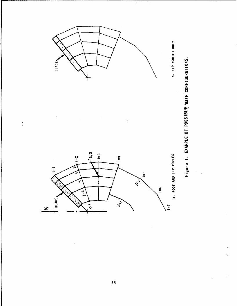
LLL
ono
Il-
.0
40
LLJ
-J
CC4 LU
it CL. Uci-
LDa
m LL.
to
35
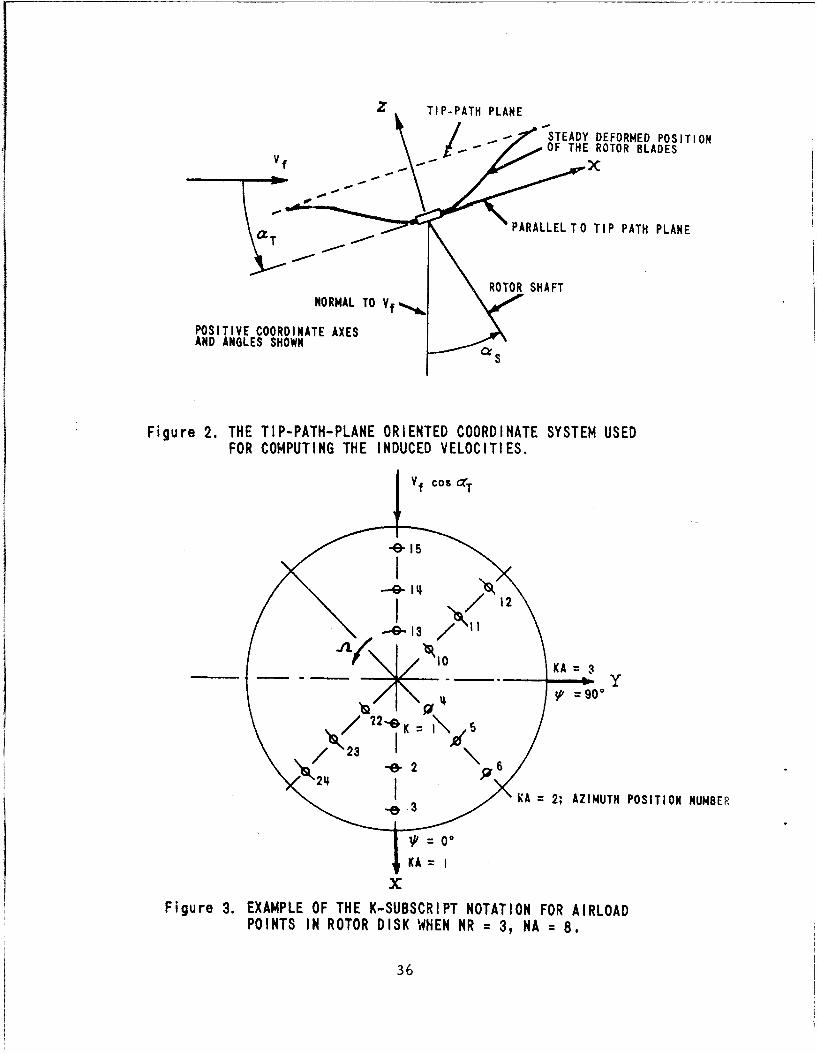
Z TIP-PATH PLANE
STEADY DEFORMED POSITIONOF THE ROTOR BLADESVf )
aPARALLEL TO TIP PATH PLANE
NORMAL TO Vf ROTOR SHAFT
POSITIVE COORDINATE AXESAND ANGLES SHOWN
Figure 2. THE TIP-PATH-PLANE ORIENTED COORDINATE SYSTEM USEDFOR COMPUTING THE INDUCED VELOCITIES.
Vf COS r
4152
137- Q1
10 KA =90
K == g 0 -
KA = 2; AZIMUTH POSITION NUMBER
KA=
xFigure 3. EXAMPLE OF THE K-SUBSCRIPT NOTATION FOR AIRLOAD
POINTS IN ROTOR DISK WHEN NR = 3, NA = 8.
36
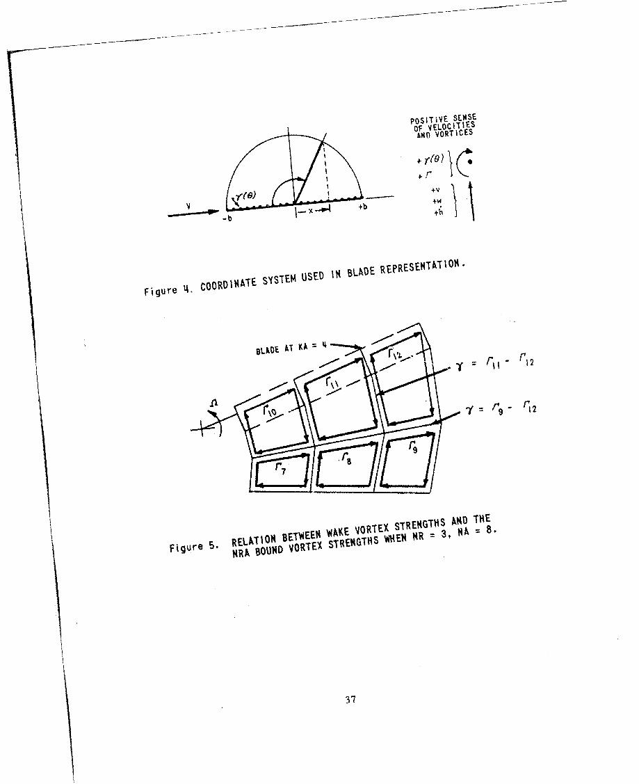
POSITE SELSE
OF VELOCITIESAwn VORTICES
+VdVJ - I._ o4 +b
Figure COORDINATE SYSTEM USED IN BLADE
REPRESENTATION"
Figure 5. RELA T'R BEThEEH WM.KE VORTEX STRENGTHS ND THE
F RA BOUHD VORTEX STREN4THS 'IiEI $R 3, 1A = ,
37
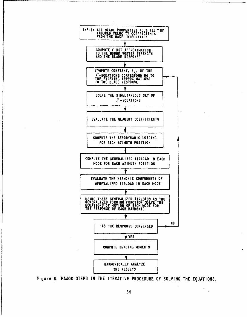
INPUT: ALL BLADE PROPERTIES PLUS ALL THEINDUCED VELOCITY COEFFICIENtTSFROM THE WAKE INTEGRATION
COMPUTE FIRST APPROXIMATIONTO THE BOUND VORTEX STRENGTHAND THE BLADE RESPONSE
fCnMPUTE CONSTANT, Ik , OF THEf-EQUATIONS CORRESPONDING TOTHE EXISTING APPROXIMATIONSTO THE BLADE RESPONSE
SOLVE THE SIMULTANEOUS SET OFr -EQUATIONS
EVALUATE THE GLAUERT COEFFICIENTS]
I COMPUTE THE AERODYNAMIC LOADINGFOR EACH AZIMUTH POSITION
COMPUTE THE GENERALIZED AIRLOAD IN EACH 1MODE FOR EACH AZIMUTH POSITION
t1EVALUATE THE-HARMONIC COMPONENTS OF
GENERALIZED AIRLOAD IN EACH MODE
SIGTHESE GENERALIZED AIRLOADS AS THEGENERALIZED FORCING FUNCTION SOLVE THEEQUATIONS OF MOTION OF EACH MODE FORTHE RESPONSE OF EACH HAF440NIC
I NO,HAS THE RESPONSE CONVERGED
YES
COMPUTE BENDING MOMENTS
HARMONICALLY ANALYZETHE RESULTS
Figure 6. MAJOR STEPS IN THE ITERATIVE PROCEDURE OF SOLVING THE EQUATIONS,
38
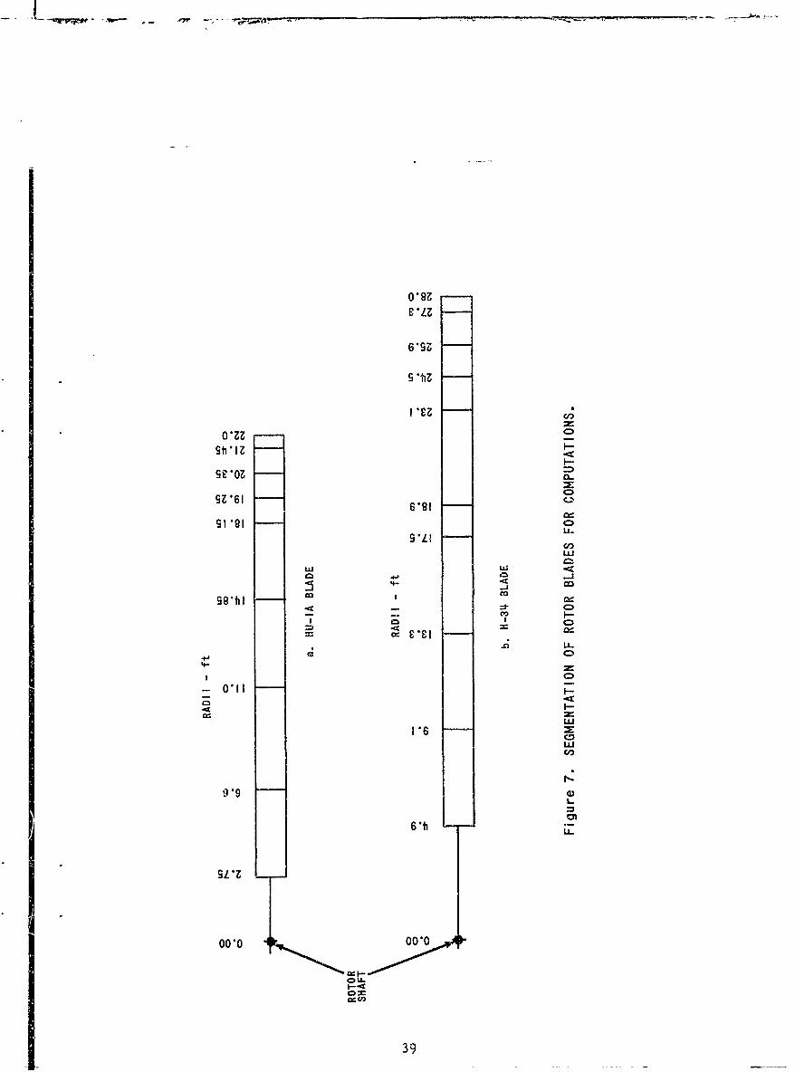
olo
o9 *t
I-
se6 IN1 (.)
CD)
S 'LU
ww
4-4
U-
4
1*6
99
6 -b
SL*ZL-
00-0 00*0
Co=
39
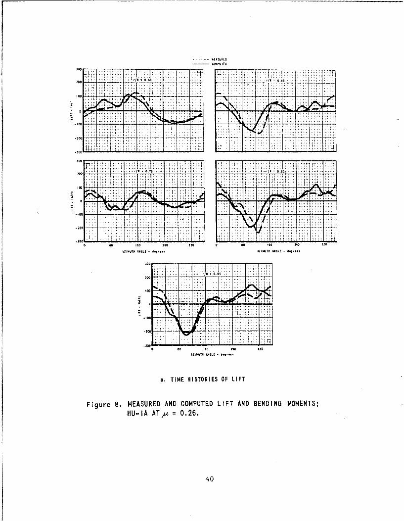
SO7C 77-, 7 77 T
77177........ ..... **.*.
tooi !" i.~
__:0 . . . .
-100.
'HI00'
v:L300- - . __:. -: U
-. o*co
otit
-20- - -"
4.-7.
-300
20004*51.
1040
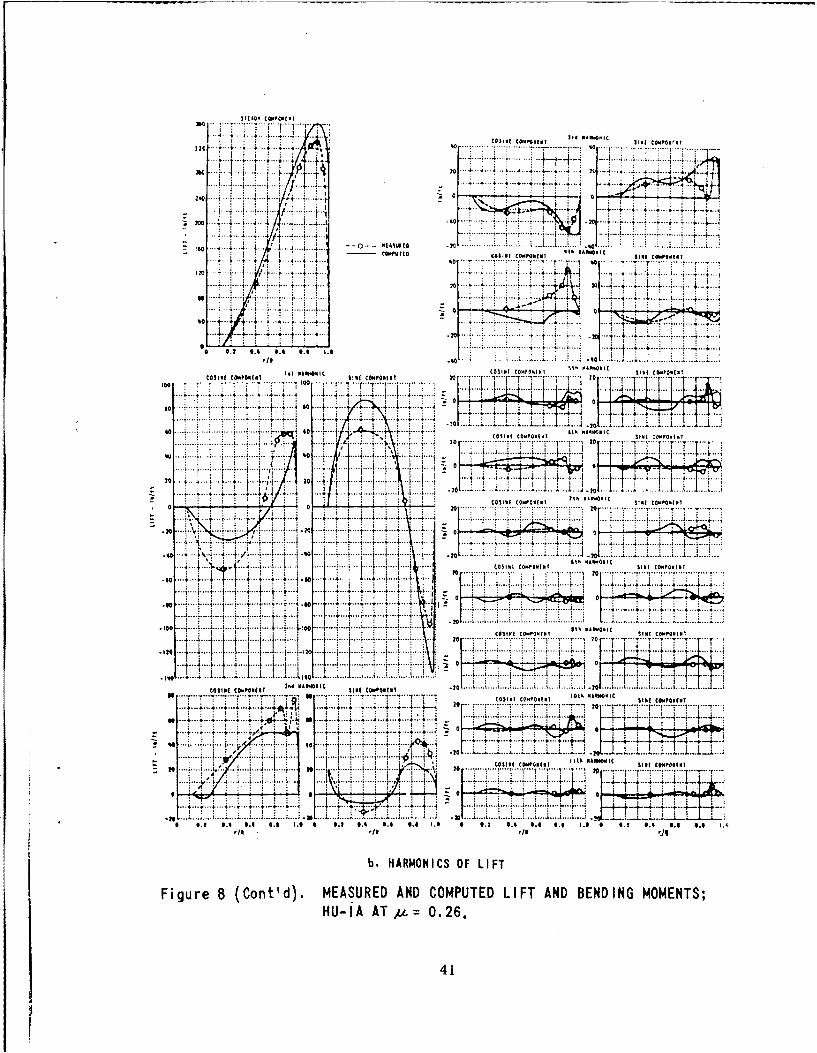
l/c 4 0 .. 4 ...... 4.
210 to -V1 . ~ 2 I....no 40 ... .14
-40.. ... .. :. tjAb 2. . ............
44
F -4, .41 ..~ .. .rT.. . N
...... .......4. 4.4 4 .. i.... : ~ i.r : ~ . 4 ~ 440 74.. ......
C0311( COMPONEN Vl COMOMI "'I~hu 20 .. .
40 T- 14
so ..... .I .4 a. .40..3 4 . .4. .
so .... 'a ... ttk A. 14, CCost,( COMPONENT St.( (0440.4
20 4L
.4 3
MINE IOP0 I St3k t343313C
v..' ... ...44 . 4.. ... .. 4 i 4 .. i
. 4..... .... * L .. 10 L .
320 4i1 i : ' 1_ I
... 20. . ... .......1
... 4.. ... .4 2
4.3.44 3.9 ......'.................... I
... .. ... .. .. t .. ... 1 . . . . . . . 4 . .t 4 . 44
....... .~3 M ... 14 I04404 .... f t *- 0430
Figur ..Ctd . MESUE AND COPTEMIFT AOPNND BENDIN MOMPOENTSVU i A.... 0.26. ..........
.. . .. .. ... . ..7 -7 .. T ..-4 1T .
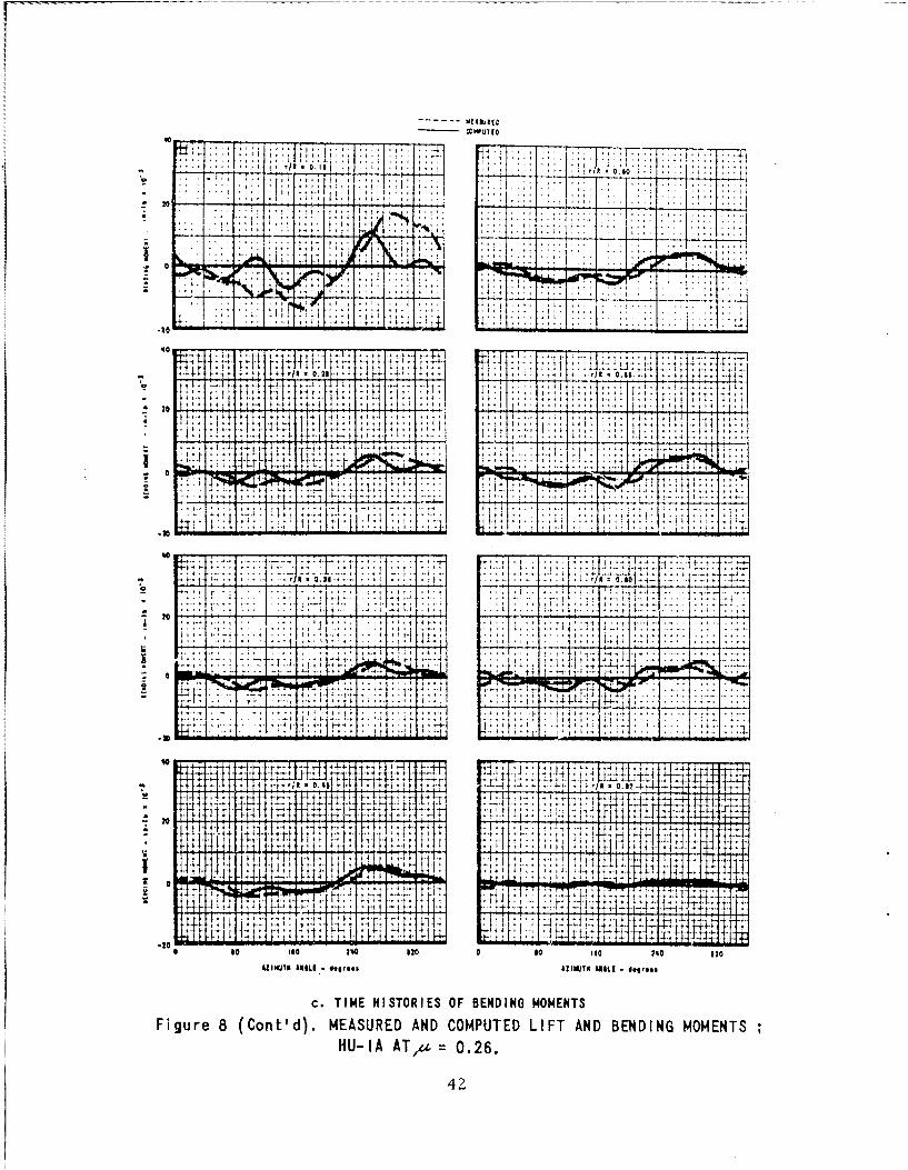
- -- * - -f -:- - - - ---.-- 4
........... ..
820'
t .4 tit 1.
At'
160 4020500* S 2
42
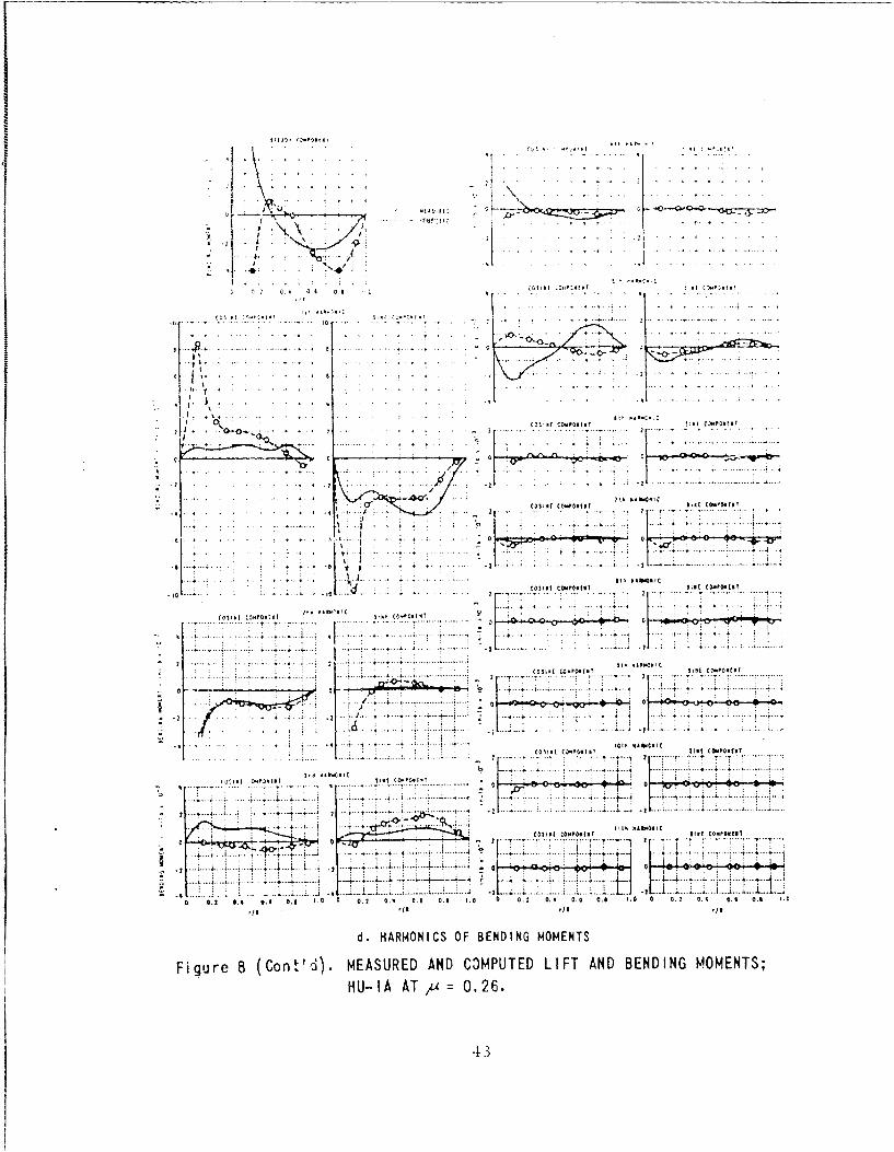
ID
411.. .. .. . . . . . .. .... 4 .4 4 4 .. ..4.. .. .. .
. .. .. .. .. .. ..
........' S ... . . ... ... t
. ........... .. o ~ ...... i
~~. ........ ........ : :.. . .. .. .. .... ..4...
0 o,. 04. -7 T 4 -T
4 . .......... ...4 .... 2
-2- 0 10 0 . o.. .4. 1. 4. . 2 .4 0.5t 4 4 0 . . 4 0. 4
di. HAMNC FBEDN.OET
Figure~ ~ ~ ~ ~ ~~~~~~*( 8 Cn440MASRDAN4041DLFTADBEDN MMNS
HU-l, I05.4 A AT /a 0.26
2 4 3
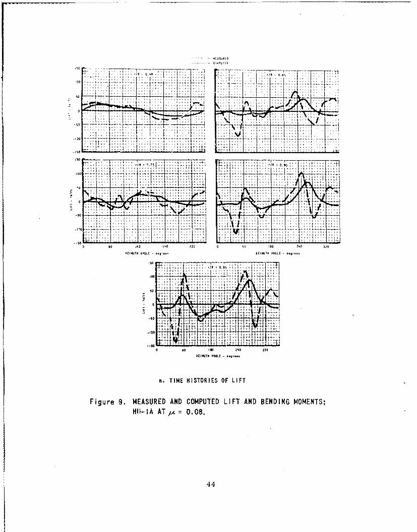
-7 0, Ito~1
-1-i
ti
-s -110 Ll .- I.
jW L - - 1: - .t ~ I -I15 1IN/R 0.11,,:::
10T0 HSOIS FLF
Figue 9 MEAURE AN COMUTE LIF AN BEDINGMOMNTS:A -AA 1 ~ .8
04
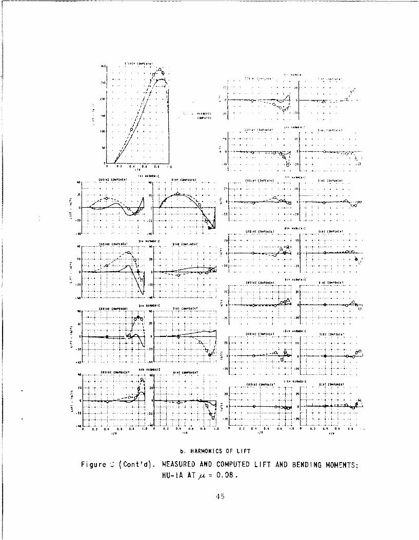
0- ! C .0o!.IM
10 wllj~ 20 a & 10 . .
202
.. ....... 4.
...........
001211 ~ ~ ~ ~ ~ ~ ~ .... ...II ~ 14 0~'( .. .. ,~
...... ........ ....... . . ...
.. .. 7 ( .... .. ... ... ..
7-0 * , .0 * I*(@2000P6.2I* 0'6
200 ....
o .. .............. .
-IS -4~.0 Slot nb.0.i
* . 4 ... 4
201160~~~~~lt CO.6I 20 C4(2.
... ... .. .. 20A4 20
.440 .... 0 . , *~. 24......0 2 06 q~ 0 .4 0.9 10 C 0.2 0,6 0.6 0.0 .a 0 0. 1 0.6 4 0 6 ;1 10 0 0.21 c.% ' s 0, a
Figure 2. (Cont'd). MEASURED AND COMPUTED LIFT AND BENDING MOMENTS;HU- IA AT/a 0. 08 .
45
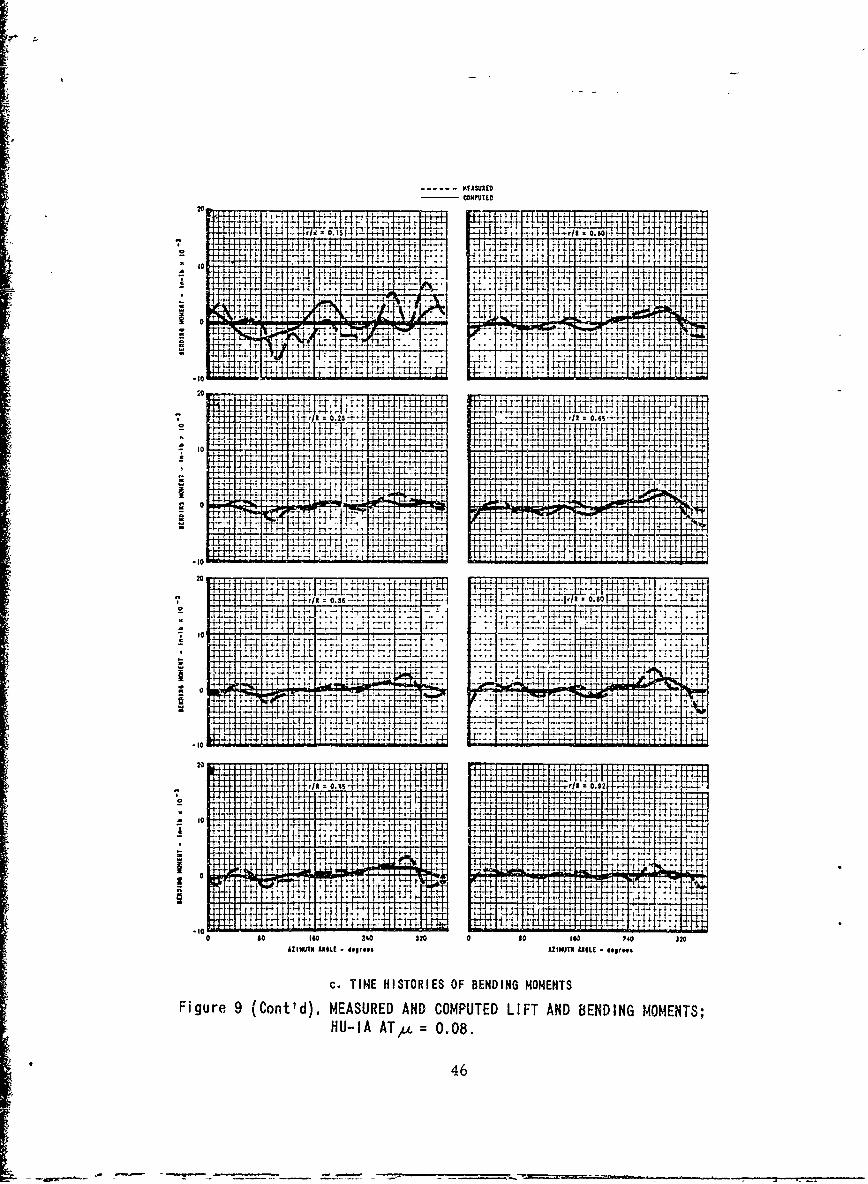
------ KFASUIED
20 r
4- z --.
- ** {~14-1442 t-h
.4.4-4
-4+. -- 7- -H f+ ~ +
-y 1-', T;
20~4 ., t 7l
0
&~~~~. -4- _ -*~4-0.2 -H-+ 1
46-
- q -i 4-' - ___
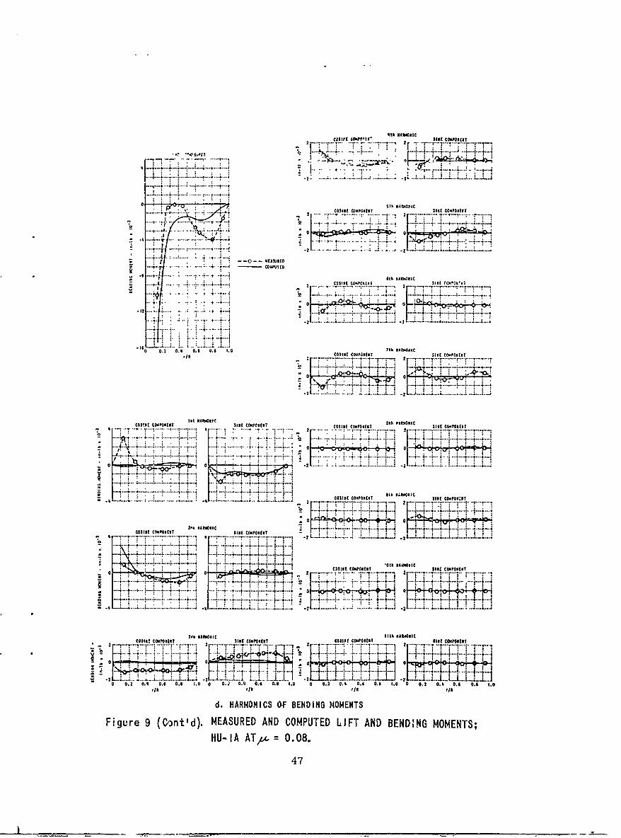
Ith RAbNDOM
2 S? ~N~~N INEo CONtCNLNT
... .. ... ... ..
0t NA ieO
2 COSINE CoNpCNENT SINE C414PONEll.... 5 .. 2 . .... . .. .. . ...... .
0 .t 4.
... ~~.. . .. . ......... .. 2...............
4-
0 0.2 5.0 .6 05 1.0 th NAWNICqo COINE co"01CNEN S INE rcmI4P11EN?
S. *..,.. ~ ........... ......... ..-.
*.. 4...4. . .. & ** .......... . . . .
-121..... ... .... . ......21Y ... 2 4..4.
-16 0 C0SIN 0. .*. . th NA0N0NIC
COSINESIN COIIPONEST SIN CEIPNEN - :'-T T .n ....................... T... '.
.................... .. N I +
- Q ... OSIE C~IPONNT INS OINPNES
.......... ... .... ..................
2 ...... . . . . . . . . . . . . . . ..... . . . . ..... .. ..
COIE ol ,I 5 i NOONONIC SIEC1ol1I th "A viONCOSSS C~0NE T IN COPO EN COSINE CCNIOoNEN SINE1 CompoNEN1
T Tt..__ _ _ __ _ _ _ _ _ ................... 2 . ......
........... ......... .. A1* ~ r ~4;~:i~z:~.Ji~f 0. 0. 1.
...0.2..0.0 . .6 .. .... ..2 0 0.........1. 0 0.rj.............
d.~ 2AMNC .... .EDN M..MENT.......... 9..... 4Cn') MESRDADCMUE IF N EDGMMNS
.......... 4 7
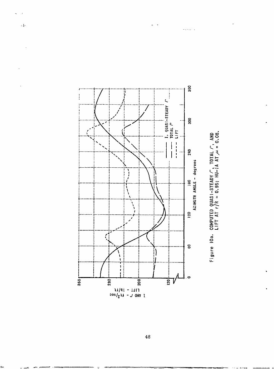
0
..........-.. . - .... . . . . .. .-, --- ,- ---
* I I a £",- o
• ~~ - - ----- --- -!,- - .,-.. ... --. ..--- -
----.---- -
tto
*------------------------- --- --------
a HH0
aN H -
a, , o *. I
tm
I • I a a -t
---- --- -- - -- - -- - - - - - - - a LlLaH0)
cIn
I- -I - - --I -
tto
----- ---- -L a---- L ----- I ----* I a a a a
,o ,, _co o o4/a a/q - I 0lI/ -a aw I
48
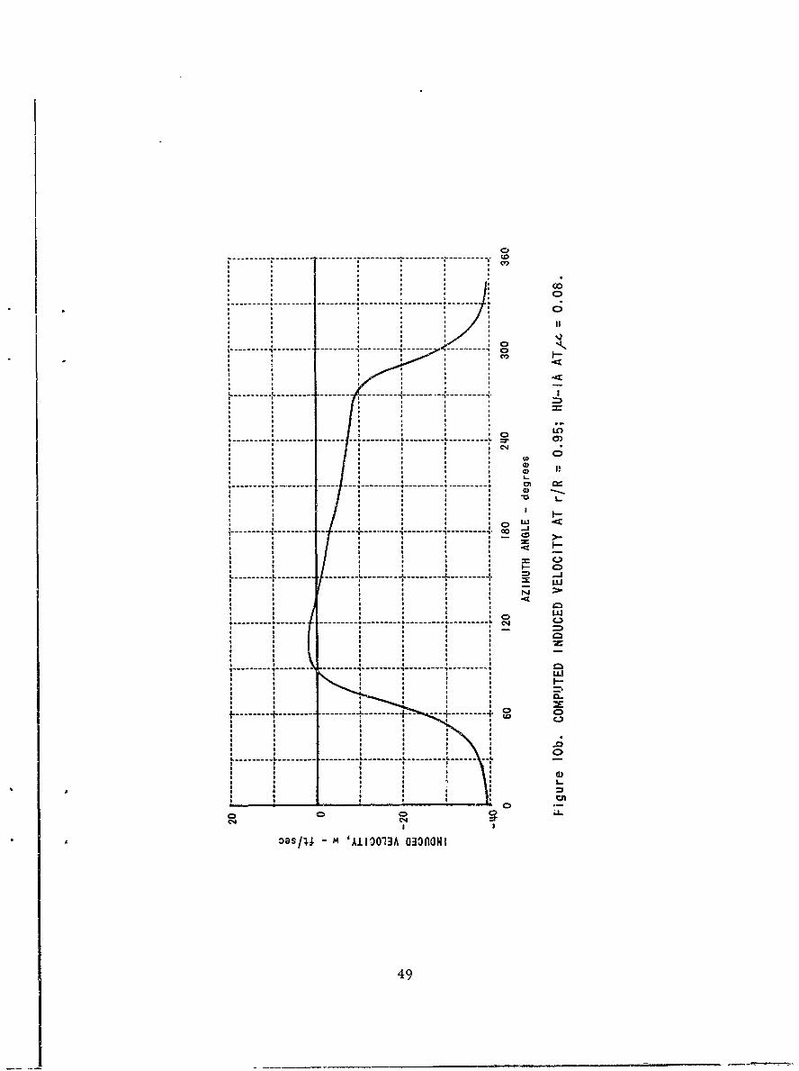
0
----------.------ -------------------iCV)
L
N
------ ----- I ------ - ----- ----
i in
, a- - - -
........+ .............. ...................
I
O s/11 M 'A1l303A QO MONI
49
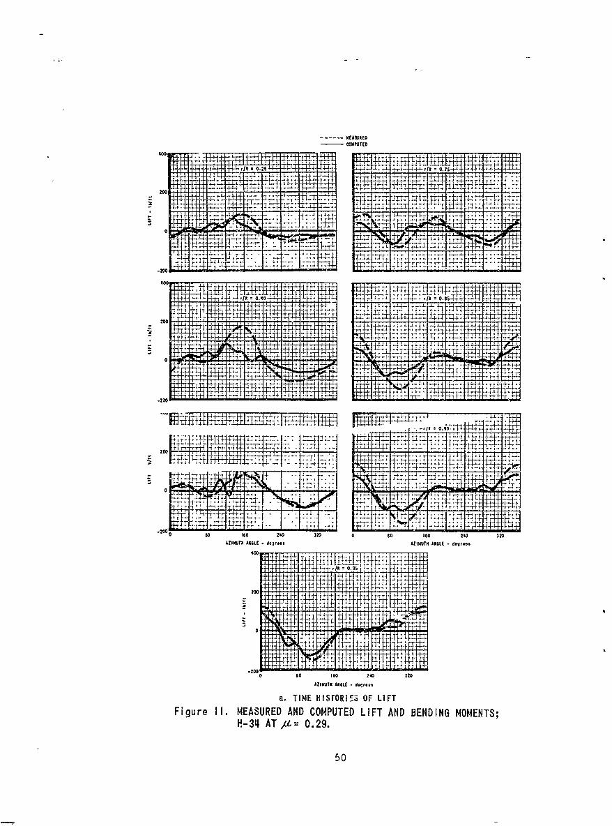
-COXPilICO
60C &~iE t~ 6.. 25 -H HL- 4 0.25 L 4 t~ tj,*.~- -~.-+- 0.
~~ *~' .-41~~~. r -: 7 F 4 -- H~.+.4 ~ ..
200
4-4
-20.
.t+ +4, 'It
200 -r *±-4
400 ~F1F4 }tT
44
2000
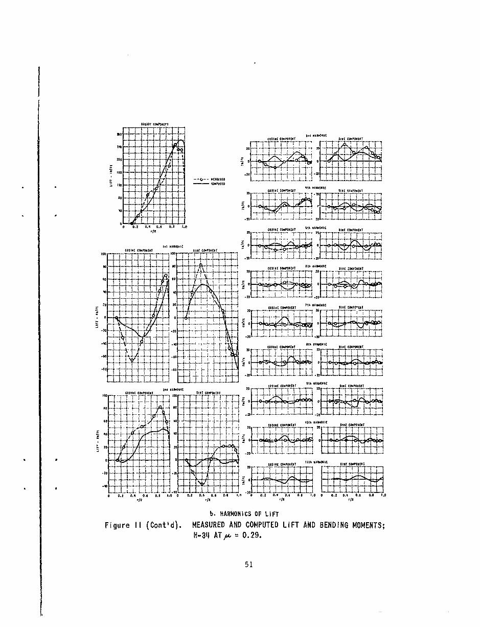
ISO .... _ ;..;. J... .. ,, ,, o+,, ,,€ ,- "
= -.---. +--- - 1--"4. ..444 COSINE CWMFNEN SN com.,.
L.-...'J...•: ~ ~ ~ ~ ~ .. ... " ' ---. -I+.......--.- :-.+L...- 110 ...... . : -i' : - l14l[
, , . ,+ + --+:, ' +,0. ................. 20 ...... "" . ...... . q. + ', .................
k + ,-. , .. ,..:o~o-... , ...... + ... ............ +. ... ... _ .. ... .. .= .+..-++1!'. { .: i + I + . , t.. L ............ ... ..... o .... ........ L - .....-
OC * ,1 v1 ,
soi
a l .... 1 i4l ASI[E W 44OSUZ $IE CtPONEtil
-- U+ 4 4-4?--e*- ... ... ...--.-.- 4------ - .-- , -... ........... .' NO'. I + + i "I : •
0 02 A. N M I
2.. L.7COSICO INPEwET $1[ SINI slOONPIM
.. ..+4 ....... .. ....... . -
-- - ---'--J -J--*--4-- -,--+ '' ..... 'J ":'* '+" P"' 'JI -- 511[-----41--Tit I(- -1 -$11. 4---III.COIN comom 4 44 % i '-A kF3. ''T CSN OPN
4+9p~~I 4. .......-- ~ -
.. ....... ----- . . . .......L ' _.... ' ..... '.++ .... "] -2 . .... .......... + ...+.. z..... +.... ..... + ... ..
-so .... . CLI .I S .MOEIC SIWPE
...- .1 . . . F. COMONEN
L. . ... .... . .. 4. - - . ... .. .. .. .. .. r-4 . .--. . ..... I+-: - !-'- -T"
S. - '. . .................. .... ........
......- --..........--4 F "-'...... .......4 ..... ........ ... ......... .... . . ... .....-I...-.-....... ... .. . ........... -. 4 ........... .-.. - .. . --. ...... ....
4. . .. +. .. .. .... ... K4--t.h- . . s. .. . 20 .. , . .,.,,.
- .. .. ,.. . O .I. . ." V
. . . . 1.. . . O POE .... .... .NI... . .. . ,: ' . .. .. . ...... .. t . . ....... ...; .. ... .............
.1,0.+ -'---'.- 4-+--: +--+-.----+--------..-...
.. I .. -4-4 4 . . .... 4 4 ........ .... .................. 4 . .. . . . 4 .. . . ..
.. . -1,
. .. 1 ..-
...." .-.....,. -.; ........ '..-L 1+ + + ,
im IT l+ +ll T I..o. mr..T -T - -.4 -r -.- ..- .- . ... ..... .........
4 ... ...... I ts ' t ic
- -2--A-f A 20 0. . . .,oo ' .. ...... .... ....... ..... ... ,00 .. -.+ -- ... ....... . . . ..
0 o... . 4 &...
FSINr dCPORMIFT ANDBDIN CMPOENTSH .... .. ..... 0.2. .... - , .... .... .......... "...... . ...........---. . . -. "- "... . .. .. '- - "" ".
, ~ ~ ~ 4 .-!- --..f- - - -+. + ... ...... .......... .
+ ... ...L.+ +... ,i+..l._. .++ .. .. ..... o . .,....... ... .. ..... ..... ..... .. + . ..4° F + i ..4..4.. ..... ...... .. ... .. ... ... -4 ,o . ........ . .L...... .. . __ .. ._ . + .:
am*4'"- .. .. :o-:-..- - -4 -04 .¢ .. .. _4 .. ... ..... T.4-4o ..;.+ . ...... 4 I - -4 -; ..-...--. ...... ..- .... i..4.... . - .j4 -F -- -=4-.- +
. " .... . ... 4 ...... - 4 4 .. 4-.-+ .t' .'-. + -A! . .210 0'...; ,, .... -. .L.. ... -L
ON 0 0.I 0.4 1.0 0 0.2 0.1 CI 0.6 I.O 0.2 0.4 0.4 0141 1.0 0 0.2 0 OA i 0 14 . 1.0
+[!+11r/I r/I
b, HARMOIlCS OF LIFT
Figure It (Contl d). MEASURED AND COMPUTED LIFT AND BENDING MOMENT$;
tH-34 AT/, = 0.29.
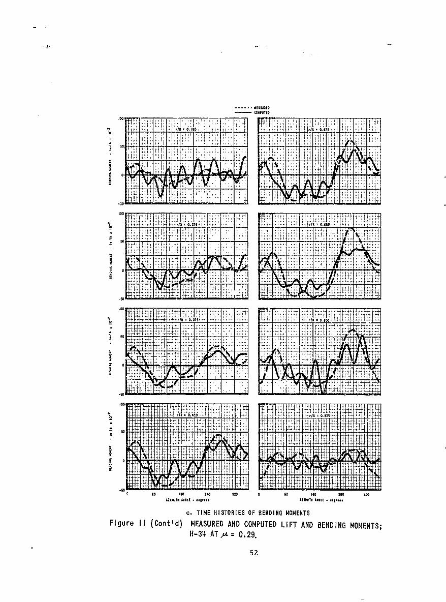
-F~ -kit
!jI
4 , 1. __ _ __ _
sor
tt
.00.
r1*c 0. . 4 t~F
00 ~~: . F 00?~h r
444 t 4 11
4F~ L j~L~r 4
g oIO 1~0 320 0 0 IGO 250 320
AZIMUTH ANSI, - .ogr.* AZIMUTH AISLE -dogrosa
c. TIME HISTORIES OF BENDING MOMENTSFigure 11 (Cont'd) MEASURED AND COMPUTED LIFT AND BENDING MOMENTS;
H-34~ ATat= 0.29.
52
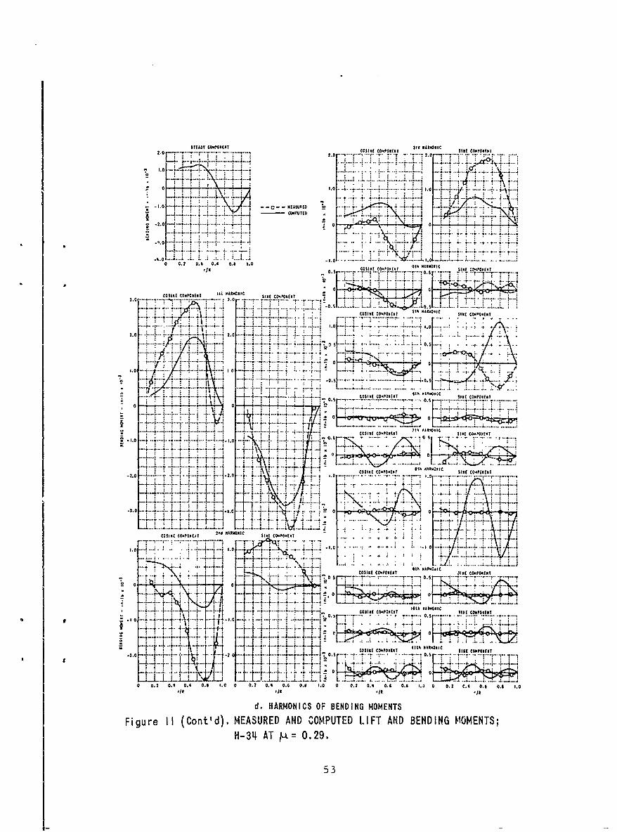
STEADY C01400NCET SId 80tlWlC2.0 ........... ... . .. .-.. COSINE CI4PONIATSl O~~,
2.0 ......... .... ..... .2.0 .... ..
...... ..NE O I .. .1 .... . - . - -
1.0 f . ......... 1-4I ... + 4 4.a~~~~..... .i .J. *.. L...~ -4 - .4 4
t4.. . --. * 4 ... 4. 4 .. 4 4 4 4 4 4 ...
.0.0 .- j. .7............
0. t 1. . ..... - . ~
t:4. .. .4.. ... 4.. . ... .
0204
. . . . . . . . . . . ... ... .-444
....... ....... ...0 .... , 7
....... .... .... ... 4... . .... 4 .... ..
4-4 t. . 4 -0. t 4. 1. 0. . ....... .. ...
COINE8 COaPOXEKT q1 MAII8oIC SINE 1-.000(C8T
....... .... ... 4T ..IJIL "Tw , ... . . .
-5.0~.. ... 44....13 0
COSIE COMPONENT l~ SINEONI Com80 CI P T ... .. ... ~ ........ ..4 . .. ... .... ..
3. r ... . ....... ~ CCNPNN
. . s h w w l1 4- ~ ........ C.....C......C........30.1. SICE CONIPINENT
+ + 4 1j ...
2. . 2. .. .. .. .. i t. + 08.~ ...... .
'I.. .. ... ....
4-3 AT....0.2953s r............
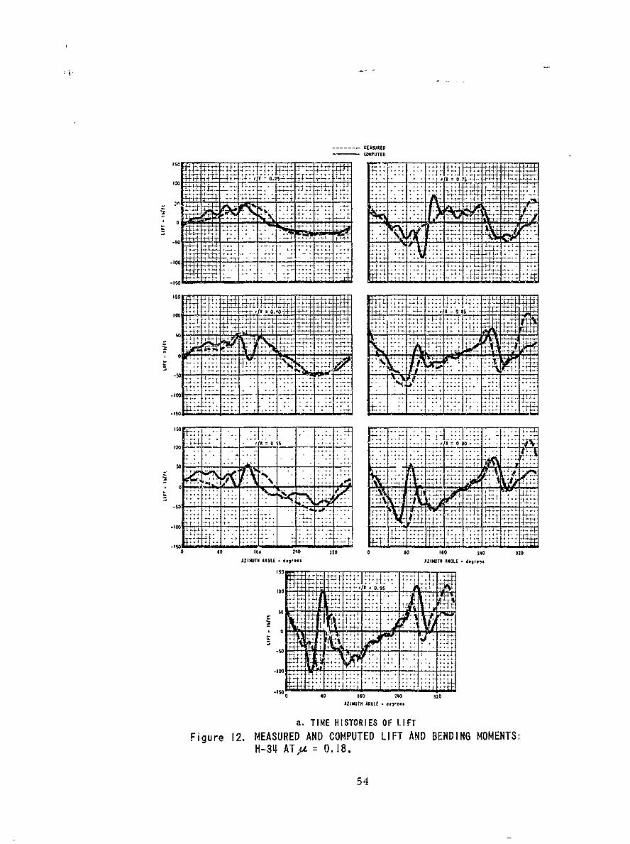
- --- EASUREOWXPtITEO
2 52T4~100 r/A 0 ? nl:r -4 T
4t?
4-4
ec J7F 4i
444
00 T6 20 2021U71 A4 4L i4e~e
a. TME HSTORES O LIT
0.4ATu= .8
54,
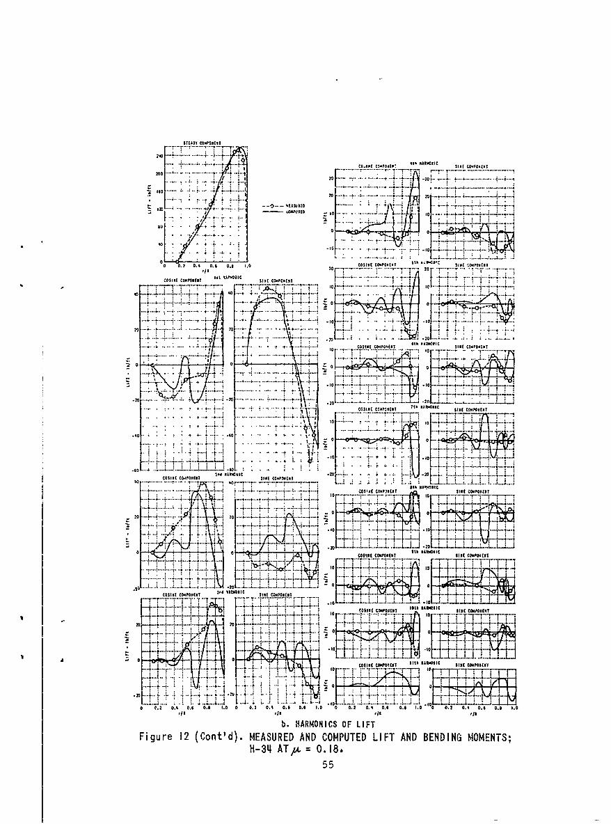
STEADY CWN02EIT
2 rD . ..... .... :. T .COth C00000tI SINE W0'10.tNT
. . . . .... ....... . . . . . . ... .
d 3 C - - 0 E C W .I + - - . - .. . . . . . . . . .. . .
++.oF- - I---!-F o , ,, , . ,
.. ..... ..
o. ...02 .. ...0;-. , ...
OS ....
tO 1+ . ..
0CO S iE CO PO E NT Sth N I 111N S E 'S I POX ENS
,/I-0 ....-.. .. . 20 --- ...
COSINE CO PONEN T r 1, a t
I 4ON NTe
t
-- . -- ,-. ... 0 ... ..... ..... . ... .-.,---........-- ....... ... .+-+ ,o... It....... :........... ...L ... ... . .. . .. ... ..]
.... ....
+ ..... ... . ..
-- 4-i- 201
. ...+. .. . .:......... .. ...... .... . . " + " ' - .o+ ' .
- - 4 - .- .COSNE CO ME T 6t ih Ma lhEC SEE o'N0.
+, ,J, , + : .. .. T" "'t.. +.
..'........
t0 10
..... . . .. ... ...
04
......... . . +- . .. .. ...... . ....+.. .. .. . . , ..... 0 .... ...+ .... ........ +.; +t :
.0 - ... . ...• ~ ~ ~ ~ ~ -0 " .. ..... .. . .. ... . . ....... .k..'
++
.......... ....... .... T T...
2PO OEOC IC .4..
. 0 ... .. .. .
" '€ 0 '0 . ' : "
........ ... .
+tto+ A
- t : -'-+: t--I -t -i~ .. . . . : - - .L ... .... .. ... ...
--- slot COMPONENT ... SE ..."...... ............... .. . ... .. ...... . .......... ... 4..:. .. ..
•~~~~~~ ..- i.L....I% + - .- ......... --.. ..... "..... CSSIN oN T.EC b .t;
S ~ ~ 0 4+4 'fINE ~COMP3nN 5hS1NNI cnc
.......... ' ... .. -
............ 4 .. . .+. . " ...... .+ ....... ..... ... .. . -+ ........... . +--4i
::' :+ o[7++++i... C+-r LU: I•.-. .... .... ,-:' + : ...... .. 44 ,4.4 , ... .
4
00
7 .[ j
- .-.....-.+" .- --+ .... +... : :- .. . ..... , ,
0, SIN r&INOrj*
Figure ~ ~ ~ ~ Cota CO(CnMd.MESREONDCMPTD T AND BEDIG OMENTS
: I...+. ... -:.... ....... ...... +.. i 14 .+ .. ... ...- -.-............ '+ + l...+.L ,....... _,.+ + ..£ .3.+3.. .L . .. :.+.. .... 4o _. .L .L .'.L .......... .. ... ... + : i '
"+.."T "T"T"Y ..' " .... ...............: ......... .....
I+- .+. .... p '. .L L , . . . . . . . -....... ..- '----'-+.. .. + , + .4 ..-.. .. .. 0.. .--. ...... .-.. ... . ... .. ... .. .---.. . .. . .
_+ ........ +. . ... . ............10 CSN W AAls w lfl
....... ... . ... ... . .. .. ... " . '.. . . . o . . . . . . - - - - . . . . ...
_ ,..i -,' ~ ~ ~ ~ ~ ~ ~ ~ ~ ~ ....., ....b.j O
', + o i t f~., .. :. + ..+ .+ .. ., . . .+ . ~ . ' + .+ .; . - .. .- ..t.o.- .... .. .L
til . ! I .':.... . ... ..... ,o...L. i :.t . .. ,L '...! . J
0 . 2, 0 . 4 0 . - 0 . 8 1 . 0 0 ° , 2 0 , 9 0 . 0 . I 1 . 0 0 0 52 0 , 4 0 . 6 0 . 1 1 . 0 0 .2 0 . 1 0 . 6 -0 . 0 1 . 0
r/Ir/Ir/k r/I
b. HARMONICS OF LIFTFigure 12 (Conra d). MEASURED AND COMPUTED LIFT AND BENDING MOMENTS;
H-34[ AT, 0 . 18.
55
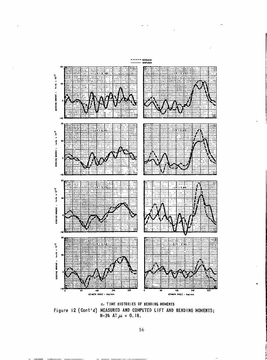
NEASWt(CMOVPUED
72 TI3 -4
-=I 2.
- - ftC0.27S -- V - -.
.5 .. JR *0.650*- 4
0 % Al
-40 z 80
-No' LTz~ 7 0.8
856
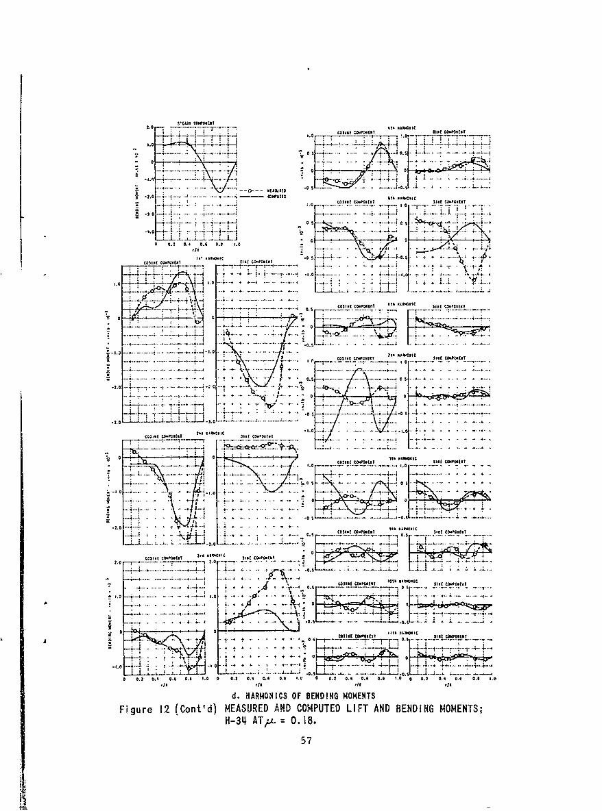
.. a.. .. 1 . . 4
....4. ..... 1*. 0.. 4 . *.*
-3**~~.4- 0 - -------- - --
0 0.2 0.4 0.1 0.8 1.0 - .-. .~..'
1. .. + .. . . . .
.. ..... I . .;. ......
4... 4 ~ ~~ .* 4...... .......... 4..4 f . . .
0 .--- --- -- .. . ........
.... 0.... . .4 . . . . + 4
... ...... ...... ......... .4.
-4 -4 4 -- -- -- -- -0 ~ * *L 4A10 1
0.5.
4..0 44 .
... 4....... 4 .. -. .4
..... .3..
20 0* O Silk p410.IC
CO.0P 1.0S1 11CO08,
.... ~~. . .. ~. . ...... .
0 S ............ ....... . 4
.4.. . . ,~~~... ..... ...... .01 * t* . - ~3, AbC.I
Li..... ..... . . 4 4T1 1 .0 10_
A4 0 MIKE constly lif C200"11T _
-- :- : I .4-., 4.
- 04
0 0.0 0.4 0.11 0.5 1.0 0 0.0 04 0.0 0 I4 S I/1 1., 0 . .,04'1 i
d. HARMONICS OF BENDING MOMENTS
Figure 12 (Cont'd) MEASURED AND COMPUTED LIFT AND BENDING MOMENTS;H-3'4 AT~ 0. 18.
57
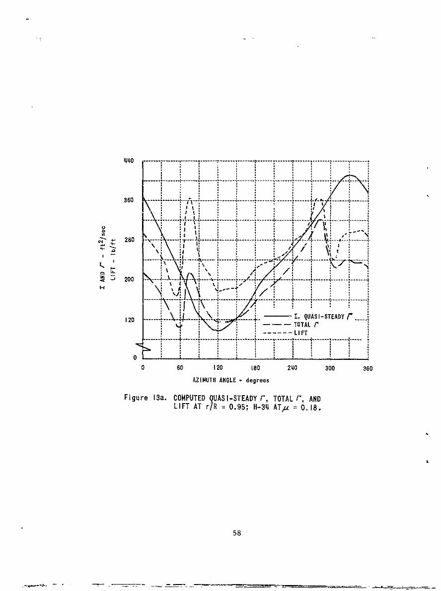
------- - ~------------------- - - - - - - - - - - - - - - - - - - - - -
* A
al 28 --- *---- - --- - I --- -- ----
o o
I ------ lo II Ion I *i I * a a *
I a *
I a ISo I a , o I
360- --.---- - -\ ' A o * a ,i / o * -.
0 * |*I
U ~-:------i------.~
• .j . : / t
120 ----- -- V 4 .... ---- , QU/.SISED r
S280 -L I
-- -- -I -- --I -- -- -I -- - - -- - - L -- - - - - - -- - - -k- - -
I l ', * a : -i / i
0 0 1 1 3
-- 7--I-, -- , ,'i l.~ */ o i
i, , F ,\--- ,' /: /! i -
Fg0 13a COMPUTE QUASI-STEAD- '
...-.L .. L ... ........ t .. --- -- ..... ....
A A = 0.858I I * a
A * I FTaa a*
Fiuea.CMUE QUASISTAD , TOTA , ANDq
LIFT AT r/R = 0.95; H-3L1 ATyu = 0.18.
58
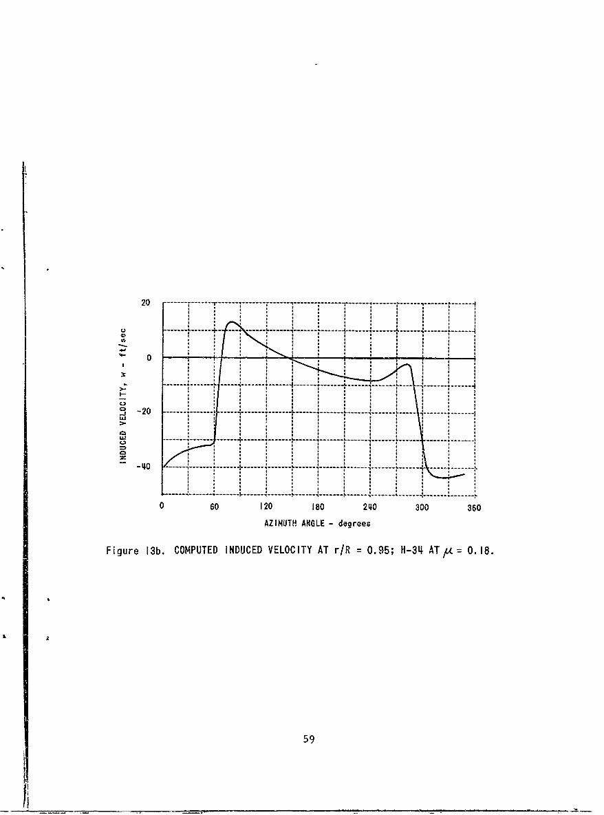
20 -------- - ---4.14-I
0
-- -- - - - - L -- -- --- - -- -- - -- - -- -
CS - 2 - - - -- - - - - - - - -- - - -- - - - - - - - - - -L - - - -- - - - - - - - - -
AZIUT 0 -GL -+ere
Fi-ue1b OPTDIDCDVLCT TrR=09;H3 T .8
05
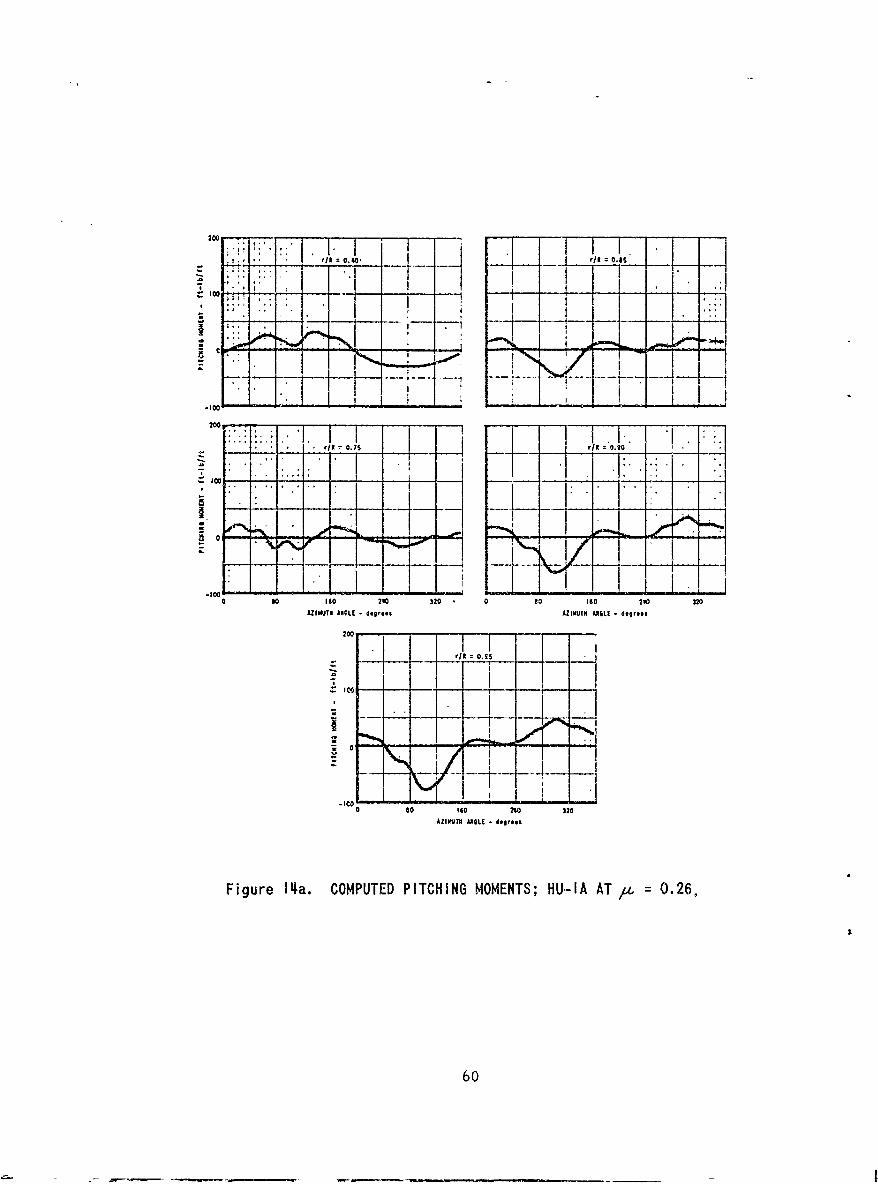
200 717.....
- " .,, .' I .* n1001
o ' * I', a i , a
- - -
0 $0 160 2110 320 a 00 160 20 320AZI4UTH AEL - dogr.s AZIMUTH ANGLE - degrees
rf 10.25
-- _ __ - _ _* .
.I
0 so 160 240 320
AZIkUTH ANGLE - degrees
Figure I1 a. COMPUTED PITCHING MOMENTS; HU-IA AT/t = 0.26,
60

rT i! r.. .. ... !. - I ,,
Al 0.0S 0 il .8 ,
* c I
--- iI , - - - -
1i00
0 30 160 2r40 3;20 0 so 160 240 320
AZIIUT ANGLE degrees ALZIMIUTH ANGLE -d€egrees
II OAS
'Y -J
0 so $0 211 120
ZlZII ATNN ANGLE 489,005eA
Figure 14Ib. COMPUTED PITCHING MOMENTS; HU-IA AT , = 0.08.
61
,,!
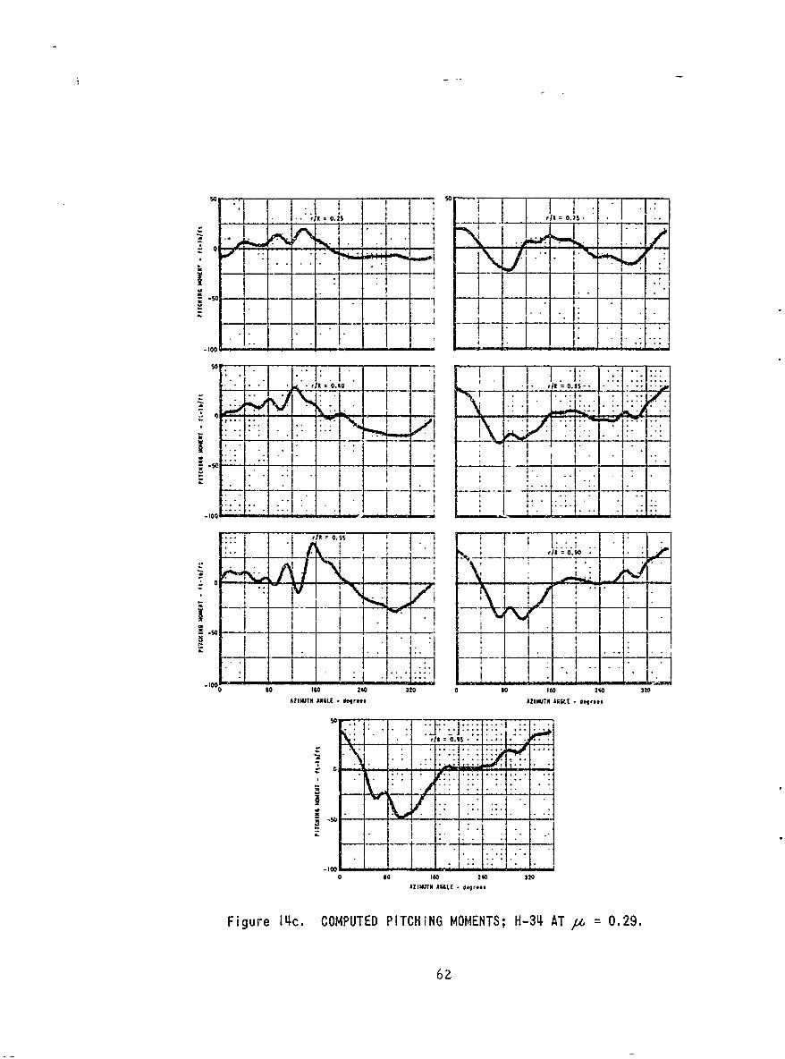
t 1 f aII 0.2 fit0.L.: - K0 47-
-10'0.40 it~l 0. s! -. -., .......".. .. .
/1. .15-ZIMH • -!A - -_ A_ -
- I - , - - -
J ! " I. :, " I Ir! ' 9 ' I .. .. ___
°10.100
$0 $e 0 0 O 10 3 0 2,Q 3
AZIMUTH Areee - do, - re- O.I- I '
.:j . - -.
(38 8 1 320 0 2 0IS 1 320
(32110TH AISE - Tgr..s AIWJN degrees
Figure 14c. COMPUTED PITCHING MOMENTS; H-34, AT /.z 0.29.
62
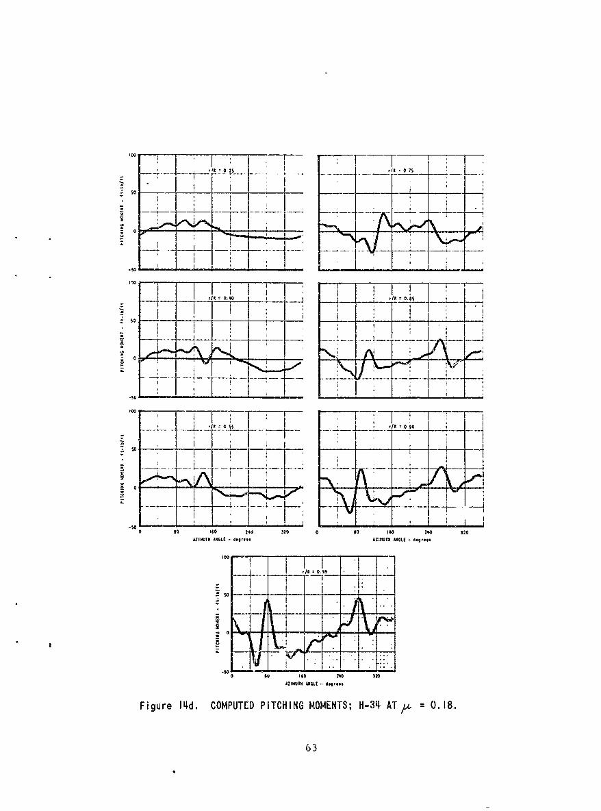
'']I t 0 OtI 0 75±50 1722
" t- _se I _ _ _ _
0 0 -
ri 0. 0, as:
-so- --. -... i - - - 0 9
080 060 280 320 0 0 110 210 320
02Il4)Tk GLC - degrbees 8Z80Th ASLE - 4g~*es
1100
-... . - "" -
... . . - ...
0 80 32 0 00 $0 3
AZIMUTH ~ ~ , MQ JAmGLE -, deresAree NLE dgre
AZIMUTH ANGE egee
Figure 1Id. COMPUTED PITCHING MOMENTS; H-3t AT, = 0.18.
63
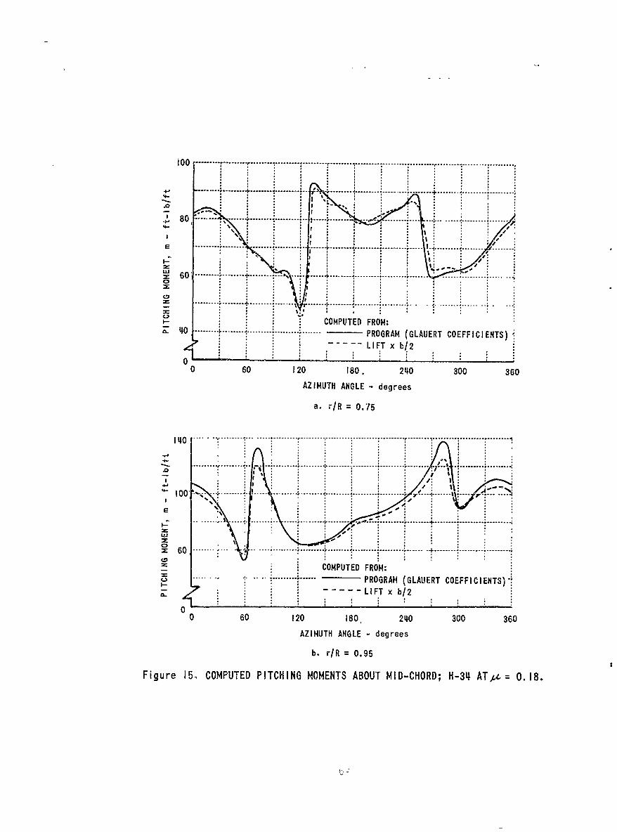
+80 ...-... ---
. .. . .. .. .. .. .. ... .. ...... ...
% I
I- COMPUTED FROM:LO -0----- ..... ... PROGRAM (GLAVERT COEFFICIENTS)
--- LIFT x b/2
0 - - - _ _ _ _ _ _ _ __ _ _ _ _ _ _ _ _ _ _ _0 60 120 180, 2410 300 360
AZIMUTH ANGLE - degrees
a. r-/R = 0.75
1410 - .... ....-----.............. ............ .............
-. ..... ...... .....
zCOMPUTED FROM:..............PROG3RAM (GLAUERT COEFFICIENTS)-
C----------LIFT x b/2
00 60 120 180, 2410 300 360
AZIMUTH ANGLE - degrees
b. r/R = 0.95
Figure 15. COMPUTED PITCHING MOMENTS ABOUT MID-CHORD; H-34~ AT~At = 0. 18.
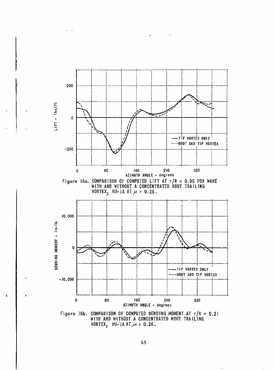
- - -- - - - - - - -t- - - ------- - - - - - - - - - - - - - - - ----------- - ---------- - - - -
20 ----- ---------------- --------------------------------
---------- I -------------- ---- --------
S S S * S0
LLSS
0 80 16 24 2
VOTE. HU I 1Tp= .2
-- -- - - - - - - - - - - - - - - - - -- - - - - - - - - - - - - - - - - - - -- -- -
10 00 -- - - -S-- - --L- - - - -- - - - - - - - - - - - - - -- - - - -- - - - - - - - - - - - - --I
* 0'--7
L * -- -- - - - - - - - - - - - - - - -i- - - - - - - - - - - - - - - - - - - -L-------
co -TIP VORTEX ONLY: -ROOT AND TIP VORTEX
- 2 , 0 0 -- --- L ------------------------- ---- -- ---L ---- ----
0 0 6 24032
AZIMUTH ANGLE -degrees
Figure 16b. COMPARISON OF COMPUTED LENIGOET AT r/R = 0.21WKWITH AND WITHOUT A CONCENTRATED ROOT TRAILINGVORTEX. flU-IA ATy = 0.26.
- -- I- - - - -4-65
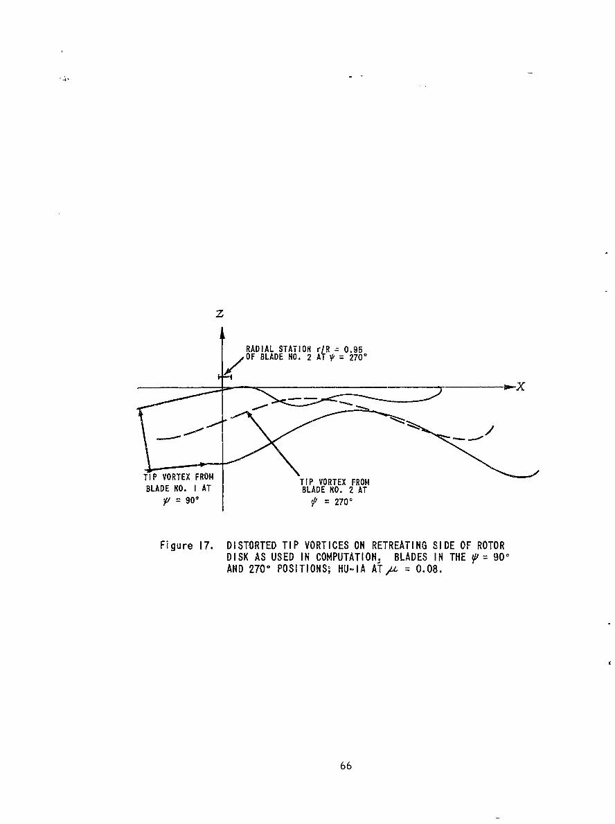
z
RADIAL STATION r/R 0.95SOF BLADE NO. 2 AT 2700
TIP VORTEX FROM TIP VORTEX FROMBLADE MO. I AT BLADE NO. 2 AT
p= 901 1 = 2700
Figure 17. DISTORTED TIP VORTICES ON RETREATING SIDE OF ROTORDISK AS USED IN COMPUTATION. BLADES IN THE 1= 90-AND 2700 POSITIONSO HU-IA AT/ = 0.08.
66
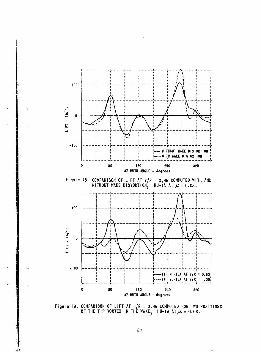
lo -- - . . . . . . . ..----------------------------- s ------
Z-5
a a: a I :1 . :
--- .----- -- -- -....... .... ........... -- - - - --- --- --- --- -- :,. . .. . .. .. . ....... ............
100* *
a'=! ! .a a .i a . a, .
-- ---, ...... ---- --- ---- ---
--~ ~ ~ i O . . . . .t . . . .... . .. . .. .. . .- . . .. . . ..-- - - - -- - --.. .. . . .. . . .. . . .. . . .. .. . . . .. "
------------------------------ J, ......... I --------- t --------- a ---- -
080 160 240 320AZIMUTH ANGLE - degrees
Figure 1. COMPARISON OF LIFT AT r/R = 0..95 COMPUTED WOT POITONOFTHIPOTAEX DINSTHERTION. HU-IA ATA4= 0.08.
.4-aa 67
.*.. . r . .. . . . . a.. . . .a. . . . . . a:
? 0 _ _ a i i
* ad
a a a iii.... ... . ... .. . aI.. . . .. .. . . .. . . .-. . . .I-. -0... . . .. .. .. . . : , ,a,
tai- TIP VOTE aTrR= .0; a--TI VOTE ATrR= o0
a.. . . .' . . . .J . . . . . . . . -a.. . .J . . . . a.. . . a.. .. . . a . .. .80 16 2a 320
IMUT AHLE degrees
Fiue 1.CMARSNOaITA r/a 0.5CMUE FO Ta O IINOFTETPVOTXI *H WAE aUI Tx =a,8
a aa7
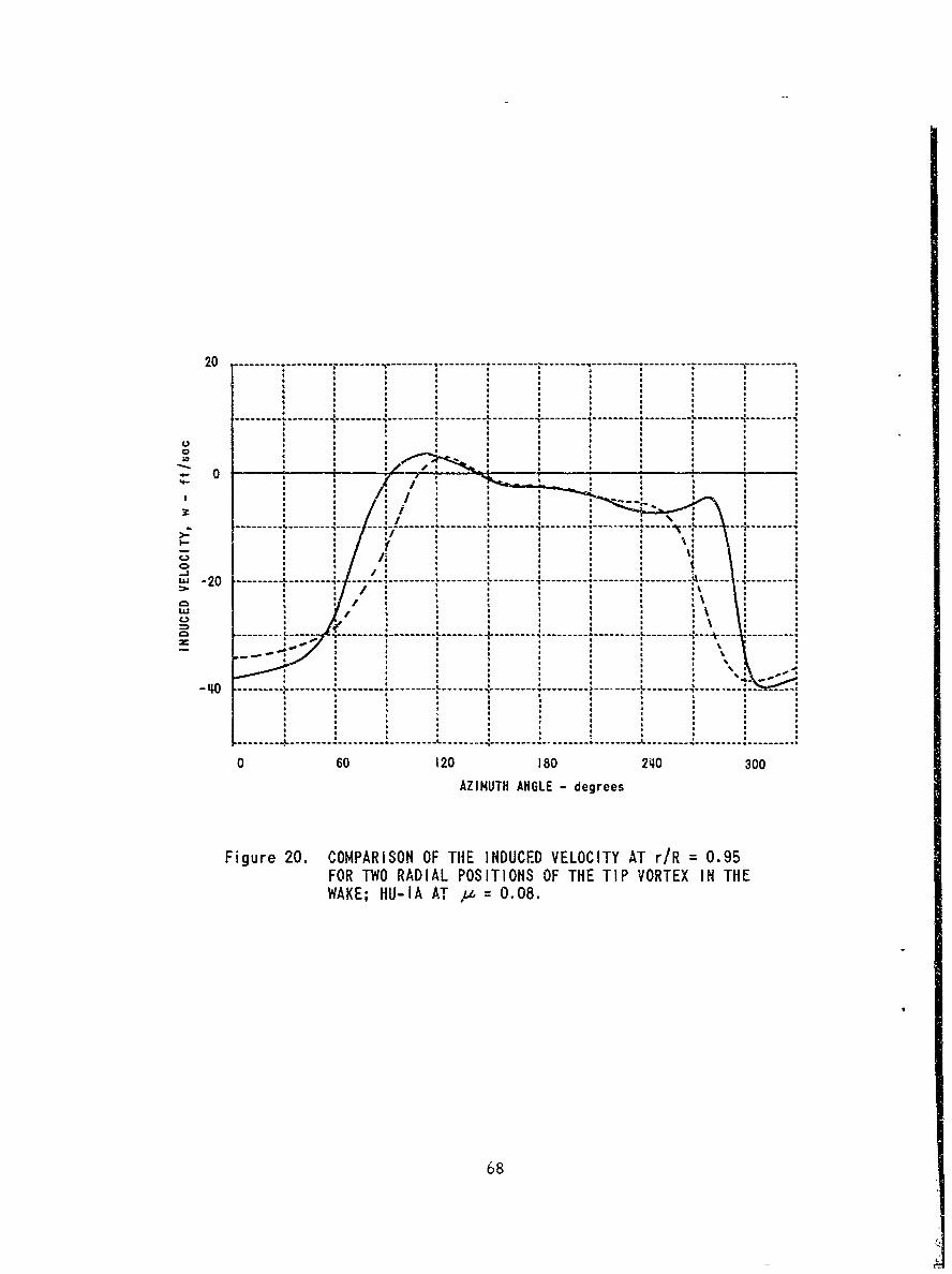
20 1 -- - - - - - - - - -- -- - -- - - - - - - - -I- - - - -- - - - - - - - - -- - - - - - - - - -
----------- - ----- ----- ---------- ----
0
3:C
--- ------------------
---------- --------- - --- -- - -- - -- - - - - - - -- - - -- - - - -- ------
-- -- - -- -- - -- -- - -- -
0 60 12 8C4 0
AZIUT GL - degee
Figure~~ 20 /OPRSNO NUCDVLCT TrR09
FO W AILPOIIN FTETI OTXI H
WAKE HUI T1I .8
IC68
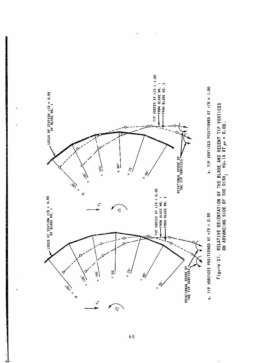
0j0f
ii.. 0
m in_
"C.
Lj C= co OF
Inc
U, 0U-~ - -c-C
U- C-
LIm Ln
U2L-J
03 -10~~c0
C- C' C )
-AJ LLL
CI
010
U,3 -
- 1,3
LIU)I0-0
0,0
691
II
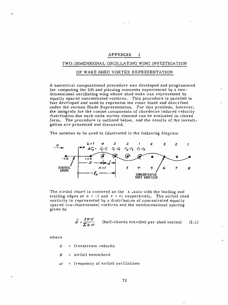
APPENDIX I
TWO-DIMENSIONAL OSCILLATING WING INVESTIGATION
OF WAKE SHED VORTEX REPRESENTATION
A numerical computational procedure was developed and programmedfor computing the lift and pitching moments experienced by a two-dimensional oscillating wing whose shed wake was represented byequally spaced concentrated vortices. This procedure is parallel tothat developed and used to represent the rotor blade and describedunder the section Blade Representation. For this problem, however,the integrals for the cosine components of chordwise induced velocitydistribution due each wake vortex element can be evaluated in closedform. The procedure is outlined below, and the results of the investi-gation are presented and discussed.
The notation to be used is illustrated in the following diagram
U k 3 2 1 3 2 '
40" .* 1.
AIRFOIL ,=1 | 5 6 7 8CHORDI
CONCENTRATEDSHED VORTICES
The airfoil chord is centered on the x -axis with the leading andtrailing edges at z = .-I and Y- = +1 respectively. The airfoil shedvorticity is represented by a distribution of concentrated equallyspaced two-dimensional vortices and the nondimensional spacinggiven by
- 2nrUd Xb (half-chords traveled per shed vortex) (I-I)
where
U = freestream velocity
b = airfoil semichord
w = frequency of airfoil oscillations
72
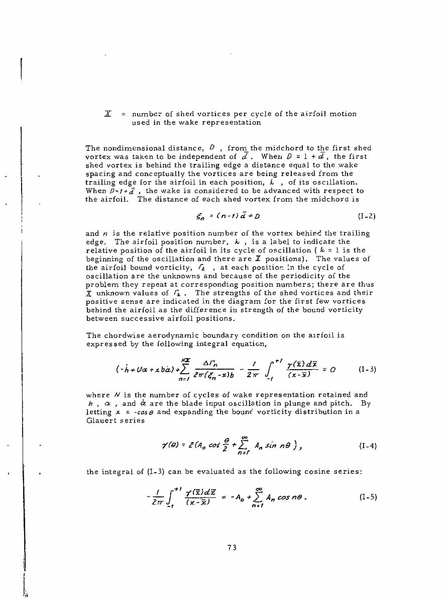
X = number of shed vortices per cycle of the airfoil motionused in the wake representation
The nondimensional distance, D , from the midchord to the first shedvortex was taken to be independent of J. When 9 = 1 + c, the firstshed vortex is behind the trailing edge a distance equal to the wakespacing and conceptually the vortices are being released from thetrailing edge for the airfoil in each position, k , of its oscillation,When O9f j , the wake is considered to be advanced with respect tothe airfoil. The distance of each shed vortex from the midchord is
, (n - f 4 D (1-2)
and n is the relative position number of the vortex behind the trailingedge. The airfoil position number, k , is a label to indicate therelative position of the airfoil in its cycle of oscillation ( k. = 1 is thebeginning of the oscillation and there are X positions). The values ofthe airfoil bound vorticity, 1k , at each position in the cycle ofoscillation are the unknowns and because of the periodicity of theproblem they repeat at corresponding position numbers; there are thusX unknown values of [. . The strengths of the shed vortices and theirpositive sense are indicated in the diagram for the first few vorticesbehind the airfoil as the difference in strength of the bound vorticitybetween successive airfoil positions.
The chordwise aerodynamic boundary condition on the airfoil isexpressed by the following integral equation,
z rn / fd (_-I- o+tba)+Z b - (1-3)
where IV is the number of cycles of wake representation retained andh , a , and 6 are the blade input oscillation in plunge and pitch. Byletting x = -cose and expanding the bounc vorticity distribution in aGlauert series
1J)2 (4 co *Z A,,sin n), (1-4)ncf
the integral of (1-3) can be evaluated as the following cosine series:
0O
f -A. +I A, cos ^. (1-5)
73
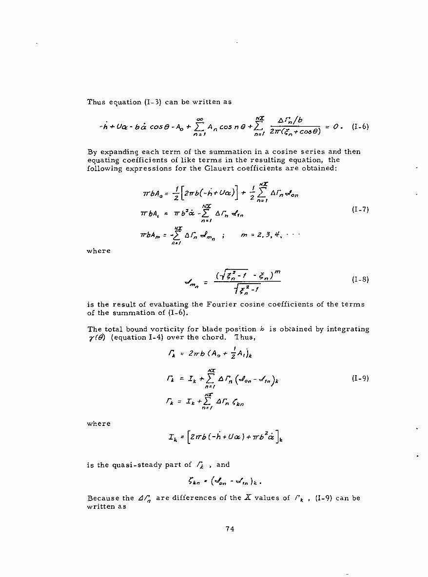
Thus equation (1-3) can be written as
h+ #Uo -b& cos6-AO n Anc0sn +L O (1-6),,I n=1 2'(4,I +co s;)
By expanding each term of the summation in a cosine series and thenequating coefficients of like terms in the resulting equation, thefollowing expressions for the Glauert coefficients are obtained:
7rbA= 27rb(-A+/9 4- UM r Y
7rb1 w2 - 1~nvi 17Z(-7)7rbA, 7 b'& -Z :A r, .n=1
7rbA,_ -Z 6 n,,, 2 - , .3., ,...
where
(j/g, - )-m, (1-8)
is the result of evaluating the Fourier cosine coefficients of the termsof the summation of (1-6).
The total bound vorticity for blade position - is obtained by integrating(9) (equation 1-4) over the chord. Thus,
2 77-b (A,, -iA,)A
r A *ZA ',(o,,-t,)k (1-9)
HX"Xt=, + Z -6 r,,n
n=1
where
is the quasi-steady part of / , and
!,,,, (-O, - ',).
Because the 01,'/ are differences of the X'values of "'k (1-9) can bewritten as
74
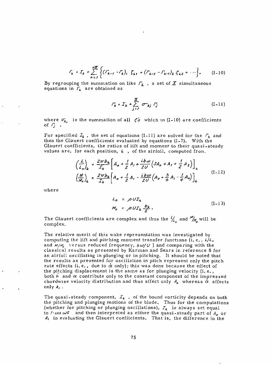
'= 4 4-Z f - r1 rk) + (.k-Z -r'.,)Z 4", *.. (1-1O)
By regrouping the summation on like /-h , a set of. simultaneousequations in rk are obtained as
fj : j Zo-kj (1-11)j=1
where aj is the summation of all ?'& which in (I-10) are coefficients
For specified 1 , , the set of equations (I-11) are solved for the f/" andthen the Glauert coefficients evaluated by equations (1-7). With theGlauert coefficients, the ratios of lift and moment to their quasi-steadyvalues are, for each position, k , of the airfoil, computed fron.
S27rb[A A, (A+A+!A)]
2fbk Ao + A, + AOA, A
where
(1-13)
The Glauert coefficients are complex and thus the ,/ and ' will becomplex.
The relative merit of this wake representation was investigated bycomputing the lift and pitching moment transfer functions (i. e. , LILoand m/l/; versus reduced frequency, bw/U ) and comparing with theclassical results as presented by Karman and Sears in reference 8 foran airfoil oscillating in plunging or in pitching. It should be noted thatthe results as presented for oscillation in pitch represent only the pitchrate effects (i.e., due to a only); this was done because the effect ofthe pitching displacement is the same as for plunging velocity (i. e. ,both h and (x contribute only to the constant component of the impressedchordwise velocity distribution and thus affect only A,, whereas & affectsonly A, •
The quasi-steady component, Ik , of the bound vorticity depends on boththe pitching and plunging motions of the blade. Thus for the computations(whether for pitching or plunging oscillations), -4 is always set equalto !-cos WV and then interpreted as either the quasi-steady part of A, or,4f in evaluating the Glauert coefficients. That is, the difference in the
75
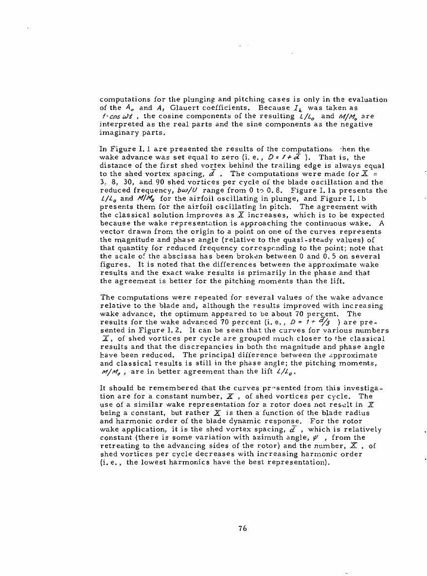
computations for the plunging and pitching cases is only in the evaluationof the Ao and A, Glauert coefficients. Because _Tk was taken asf-cos Wf , the cosine components of the resulting L/L o and tu/M/ are
interpreted as the real parts and the sine components as the negativeimaginary parts.
In Figure I. 1 are presented the results of the computation- 'hen thewake advance was set equal to zero (i. e., D-- /4- ). That is, thedistance of the first shed vortex behind the trailing edge is always equalto the shed vortex spacing, d . The computations were made forX =3. 8, 30, and 90 shed vortices per cycle of the blade oscillation and thereduced frequency, bco/U range from 0 to 0. 8. Figure I. la presents theL/10 and H/O for the airfoil oscillating in plunge, and Figure I. lbpresents them for the airfoil oscillating in pitch. The agreement withthe classical solution improves as X increases, which is to be expectedbecause the wake representation is approaching the continuous wake. Avector drawn from the origin to a point on one of the curves representsthe magnitude and phase angle (relative to the quasi-steady values) ofthat quantity for reduced frequency correspcnding to the point; note thatthe scale of the abscissa has been broken between 0 and 0. 5 on severalfigures. It is noted that the differences between the approximate wakeresults and the exact wake results is primarily in the phase and thatthe agreement is better for the pitching moments than the lift.
The computations were repeated for several values of the wake advancerelative to the blade and, although the results improved with increasingwake advance, the optimum appeared to be about 70 percent. Theresults for the wake advanced 70 percent (i. e., D = I + d13 ) are pre-sented in Figure 1. 2. It can be seen that the curves for various numbersX, of shed vortices per cycle are grouped much closer to the classicalresults and that the discrepancies in both the magnitude and phase anglehave been reduced. The principal difference between the approximateand classical results is still in the phase angle; the pitching moments,Avl/lAl , are in better agreement than the lift L/L o .
It should be remembered that the curves pr-sented from this investiga-tion are for a constant number, X , of shed vortices per cycle. Theuse of a similar wake representation for a rotor does not resclt in Xbeing a constant, but rather X is then a function of the blade radiusand harmonic order of the blade dynamic response. For the rotorwake application, it is the shed vortex spacing, d_ , which is relativelyconstant (there is some variation with azimuth angle, V1 , from theretreating to the advancing sides of the rotor) and the number, X , ofshed vortices per cycle decreases with increasing harmonic order(i. e., the lowest harmonics have the best representation).
76
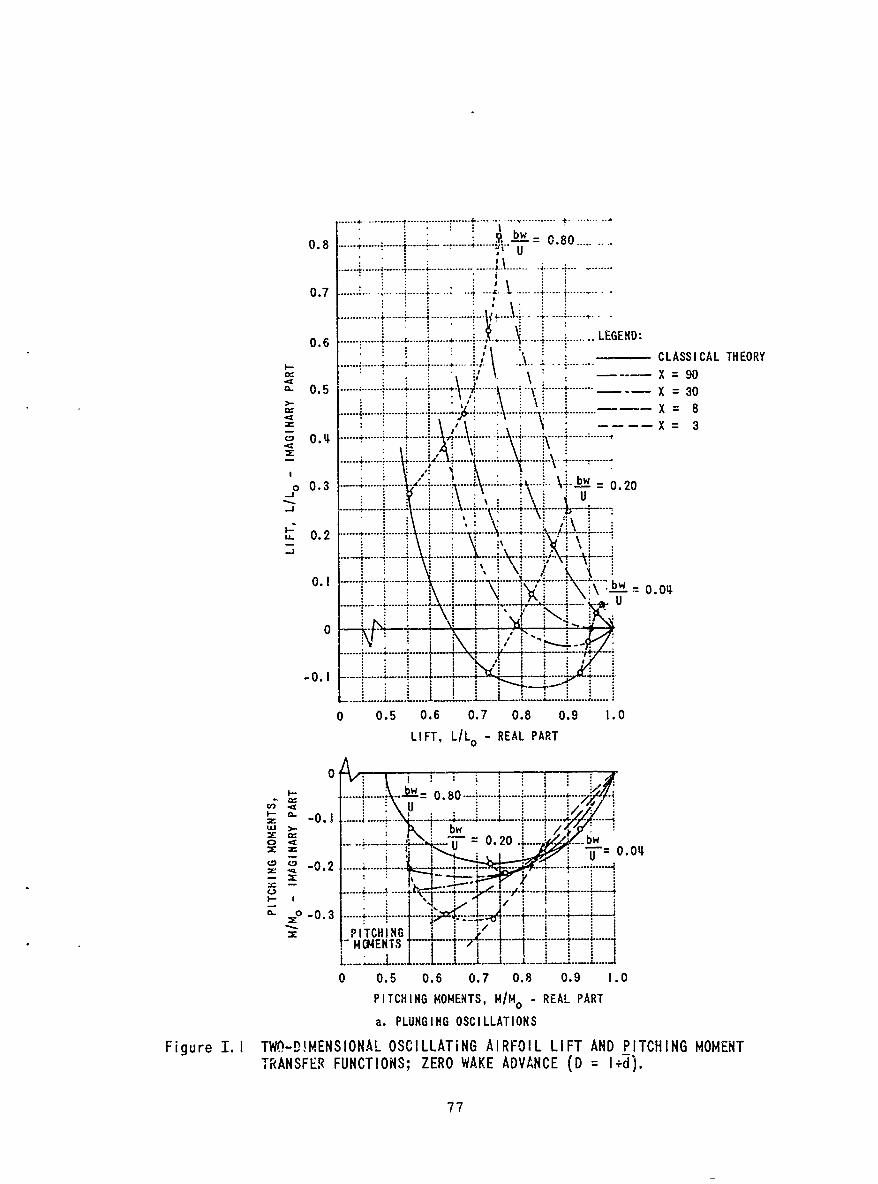
....... ---
-- --I...... ---
0.8 .... ...I ... b.............. w = 080 .;' U
A......................
0.6........... ..... ... .. .. LEE D
.............................. ....
0 ........4.
-X 30
00.3.........X..
XI U
.... 0 2.... . ...
0. -LW 0. 2
LL- ~ ~ 0 0.8 0.9.. .10. .... 4...
0.0.... 080 .... .
., .. .. .U
S-0.2 . ....... --- ..
....... ..... .. . ... ..
0 0.5 0.6 0.7 0.8 0.9 1.0
PICIFTG /OT -I RELPREATPR
00
a....... PLUGIN OSCILLATIONS.4 ....
Figur U.ITODMNINLOCLAIGAROLLF N ICIGMMN:rAN RFNTOS ZERO WAKE. ADV.NCE (D.. ......
77
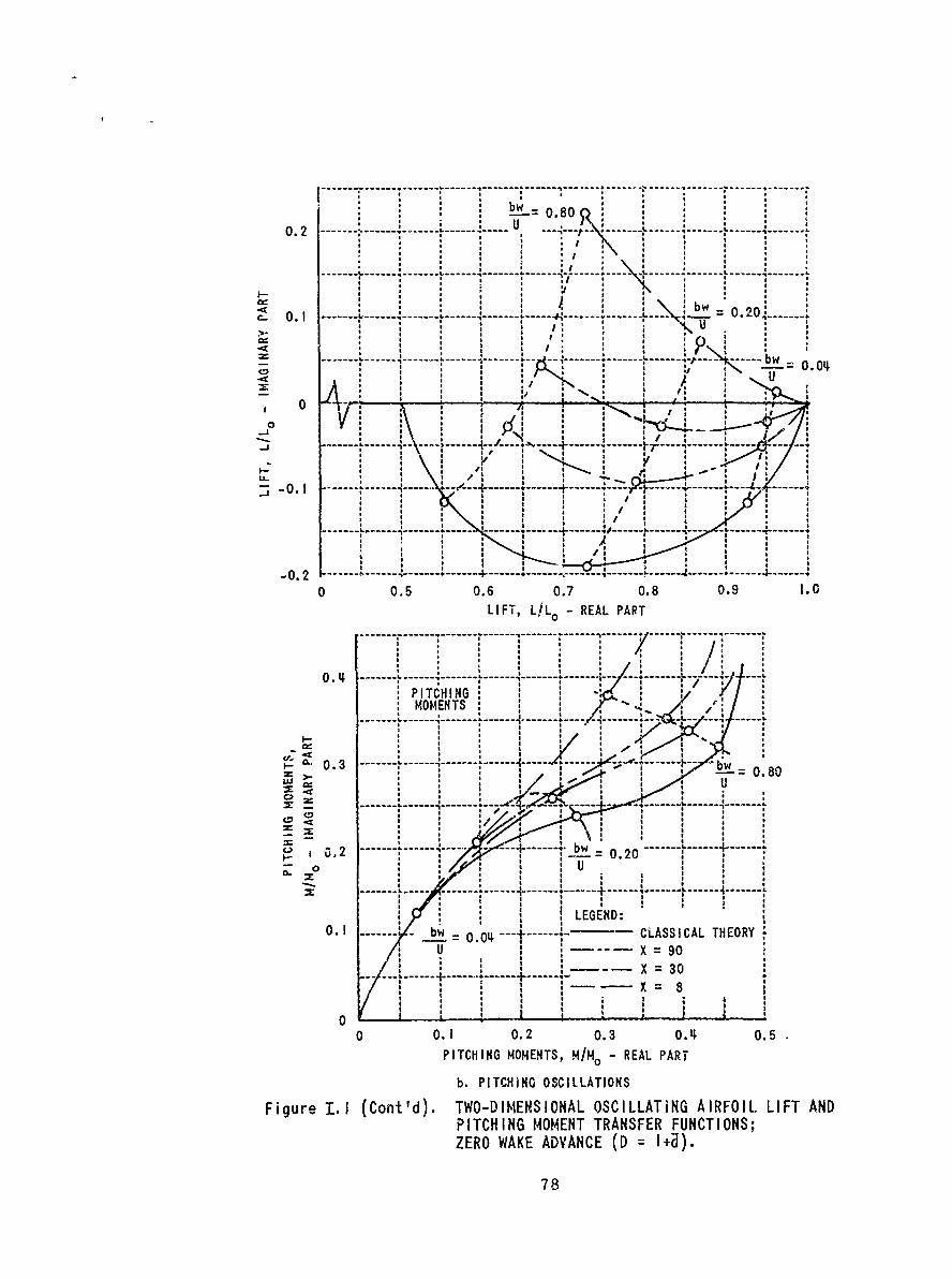
-------- -- -- - - - - - - -- - - - - - -
-=0.80
-- -- - ------- -- - -- ---
-------------- ----------------------0.2----0.0
a a a a
0. ----- a-- I ------- Z0 1-----------
.41 a a a
- I-T, 4 4-o _ REA PAR-- -- -- - - - - - - - - - -- - - -- - - -- - -- --- - -- - - - -
0. ---------------- -------- £- ---- L7 -
PIaTCHINGMOMENTS
a.------------- -----
-------- . ---------------
0 U---- ---- --- - a---- ...
- 01 -. 0-4 -- CAS A L ER
+---a - --- - - - - -
aX a a
0
0 05 1 06 2 07 3 0.8 09 .5LIC IFT, MOENS/L - REAL PAR
b.PICHNGOSILATON
Fiuea. aCn ') aW-IESOA OS IA iG IROL IF AN
PITCHING MOEN a RNSE FUCIOSZER WAKEAVNE(
MOMENT a a 8
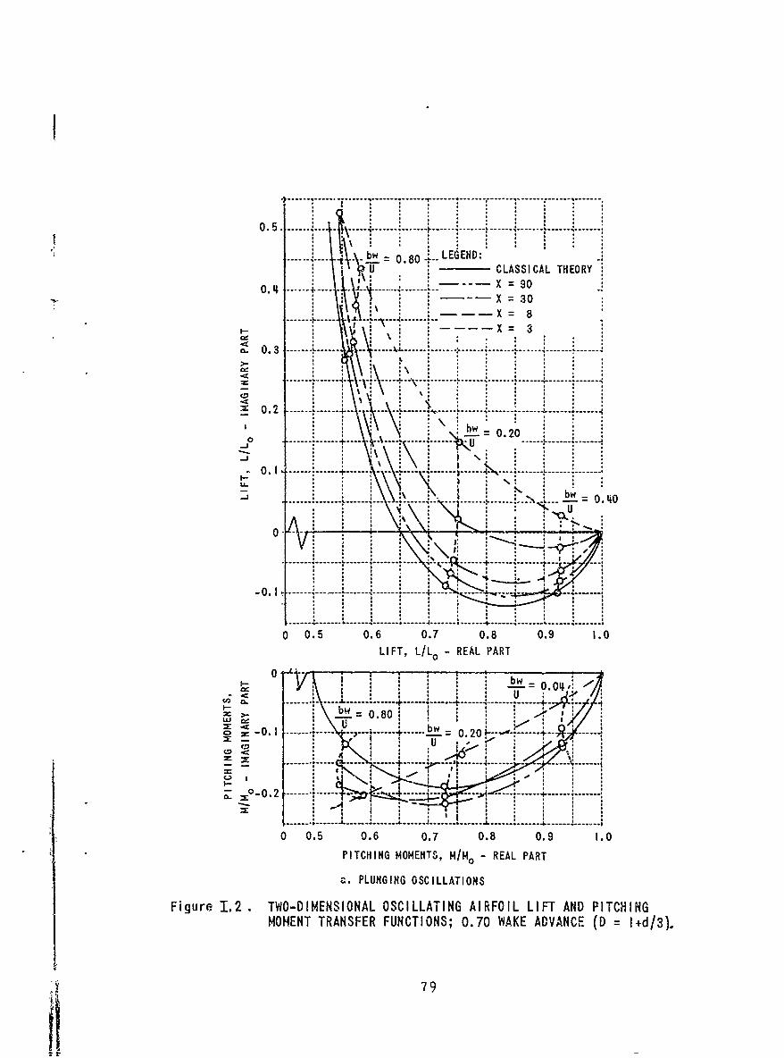
----- 0.80 _LEGEND:CLASSI CAL THEORY
0.11 4 -- - X = 90X =30
X 8X 3
(L 0.3 ------- -- --- ---- ------- --- ---
g 0.2 L 0-- - -40-- ---- -----
* b
0 20
0.5 06------- 07 0.8--- 0. ---------- 0----
X V .....0..o 0.4
04
0 0.5 0.6 0.7 0.8 0.9 1.0
PICIGMOT, H/M0 REAL PART
~~~~.~0 PL0GN OSILAIN
Figure 1.2 . TWO-ESOA OSCLLAIN AIFOLLITA---T~IMOMNT RANFERFUCTINS;0.7 WAE DVACE D =I~d3)
794it-------
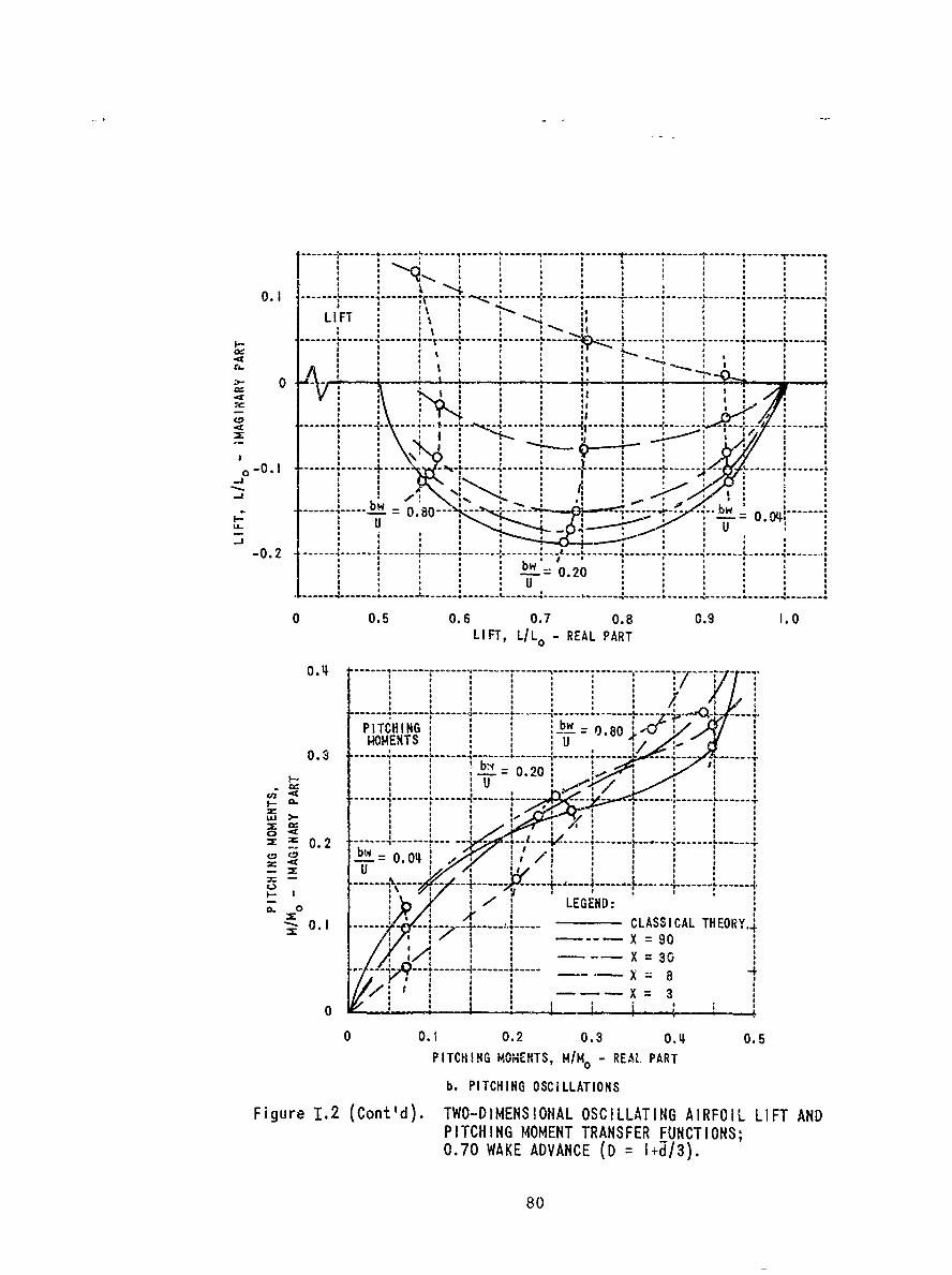
------- ---- -*---------
- - -- ---O . I . . . . . . . . . .. . . . . . . . . -.. . .. . .. . .. . .. . .. . .. . .. . .. . .. . .
LIFT ** "SS " I
. . ..-- . . . . ..-- .. ...... , -.... .. ,. ....... II 4 - bw .......
I.- * , I ,'t , .
U 00kI -_ 0.20
-------- ---- 4 -------- 4 ---- ---- ---- --------
0 0. 0.+. . . . .
LF , , , REA PART
z : \ .i ! -------------- ----- '
PIC 080 G - * o ' , b.80o- .U....... .- : : J : i " ,P.
0.20.20
U
---- --- - ---- -- - - - - - -- --
LI -T,--. .R
e0
m- 0 .2 -- -- -- - - ------.. .. -r .. .. . .. .T
*i i
0.5 0.6 0. .004 .
I FT LL RELPR
8 ,
----... -- - - - -- - - - -
* I
PITH IGHEXTS U~ ,.
LEGEND
;- --- ---- -
-4-
"-~ = 90"'X = 30':
- 2-- ----- --- ------------ X 3
a~0
/ X :90:I CLASICAL TX:R30IA .,
0O.1 0.2 0.3 0. 0.5
PITCHING MOMENTS, H/Mo - REAL PART
b. PITCHING OSCILLATIONS
Figure 1.2 (Cont'd). TWO-DIMENSIONAL OSCILLATING AIRFOIL LIFT ANDPITCHING MOMENT TRANSFER FUNCTIONS;0.70 WAKE ADVANCE (D = I+d/3).
80
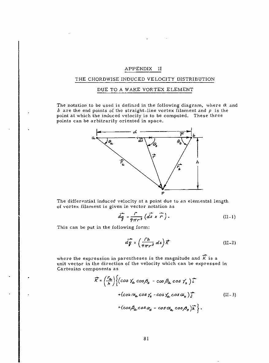
APPENDIX II
THE CHORDWISE INDUCED VELOCITY DISTRIBUTION
DUE TO A WAKE VORTEX ELEMENT
The notation to be used is defined in the following diagram, where a andb are the end points of the straight-line vortex filament and p is thepoint at which the induced velocity is to be computed. These threepoints can be arbitrarily oriented in space.
K -*7-b
r!
P
The differential induced velocity at a point due to an elemental lengthof vortex filament is given in vector notation as
This can be put in the following form:
--I (~~s) Ph-2
where the expression in parentheses is the magnitude and K is aunit vector in the direction of the velocity which can be expressed inCartesian components as-(O ( COA OS,, C-
+. COSfo , COS4 - Co's
~(roslA osz - cos ctCOA k}
81
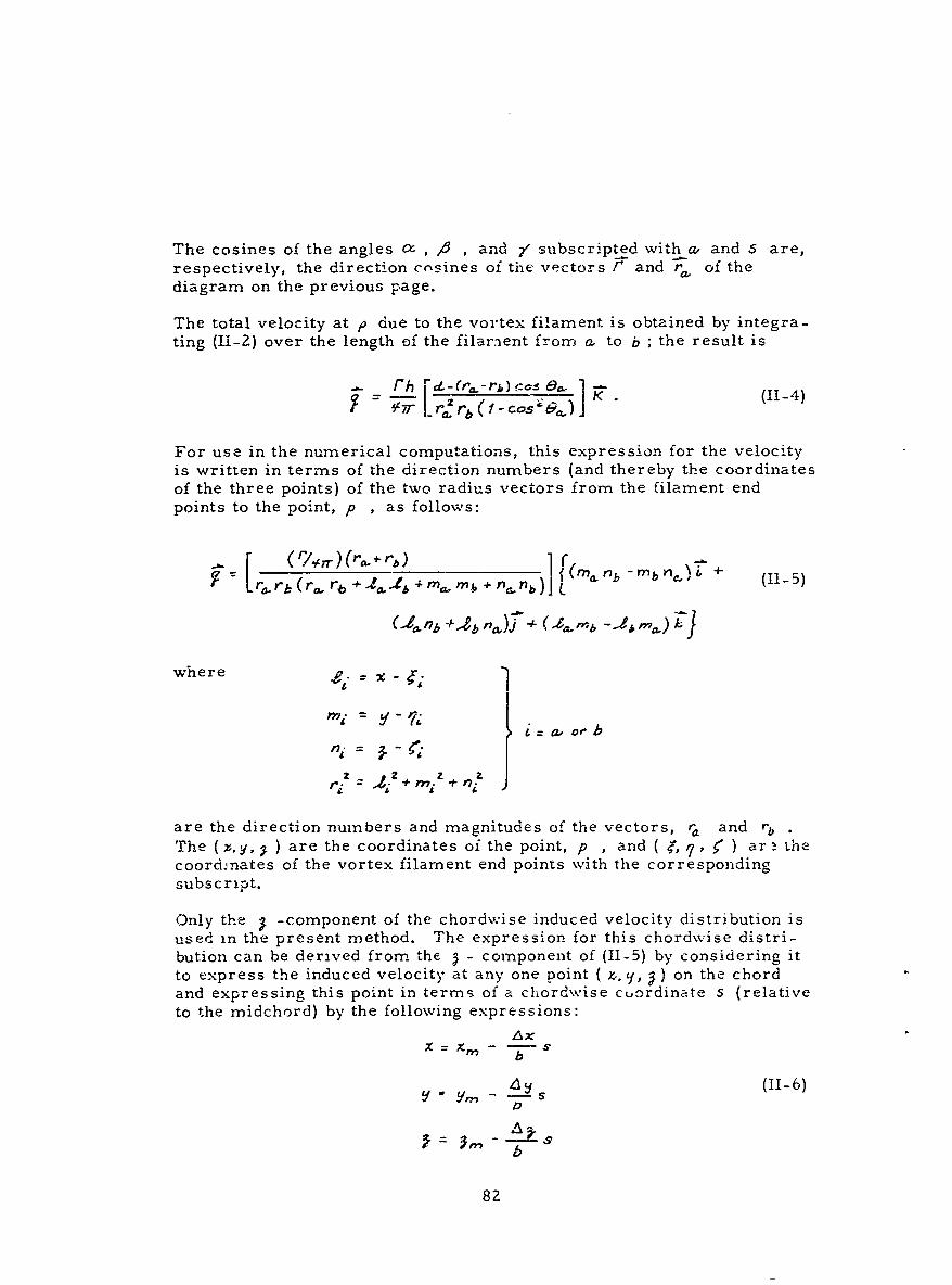
The cosines of the angles a , , and / subscripted with a, and S are,respectively, the direction cosines of the vectors F and ra, of thediagram on the previous page.
The total velocity at p due to the vortex filament is obtained by integra-ting (11-2) over the length of the filaraent from - to b ; the result is
rh [d.- (-r) ce- 1
a, I2tb(f - cos ']K.(14
For use in the numerical computations, this expression for the velocityis written in terms of the direction numbers (and thereby the coordinatesof the three points) of the two radius vectors from the filament endpoints to the point, p , as follows:
[ r, n rh r r b (11 m b (I-5)
where p"
'ni = 7i i= a, or b
ni 4' ,o
z + z a
are the direction numbers and magnitudes of the vectors, r and rz
The (x,0y, ) are the coordinates of the point, p , and ( e, q, <' ) ar thecoordinates of the vortex filament end points with the correspondingsubscript.
Only the -component of the chordwise induced velocity distribution isused in the present method. The expression for this chordwise distri-bution can be derived from the - component of (11-5) by considering itto express the induced velocity at any one point ( x.. , i,) on the chordand expressing this point in terms of a chordwise cuordinate s (relativeto the midchord) by the following expressions:
L x
- _,- !f (11-6)2D
82
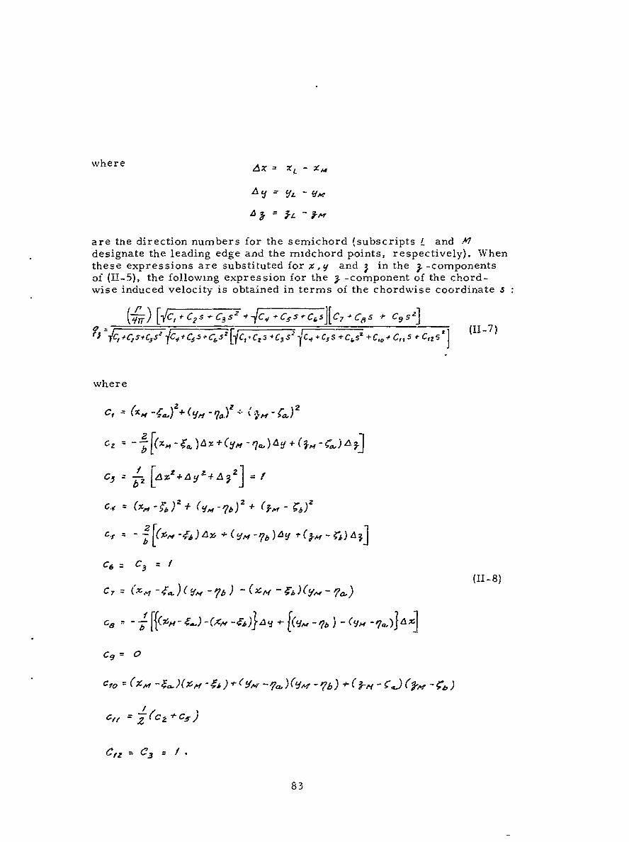
where A- x
A = ' -.
are tie direction numbers for the semichord (subscripts L and .4designate the leading edge and the midchord points, respectively). Whenthese expressions are substituted for %, y and in the . -componentsof (H-5), the following expression for the L -component of the chord-wise induced velocity is obtained in terms of the chordwise coordinate s
H 7r ) [3C C 5 j [ 07 5 -1- C9 s i
TCI ./c,5ITc37F9 fC ~t 5 5~6 5 C6,5 UC _CZC 3S 2 _F C_S+ C's +C C, 1 -c,zs2 (-7
where
2
bR
2 L
C.i [(cV-,6 y + i1M -b )AYf (,ZH-~
C6 = C3 = /(II-8)
c, : (,,, - ) H -f -qw - )6,,
z, 2 C C48
83
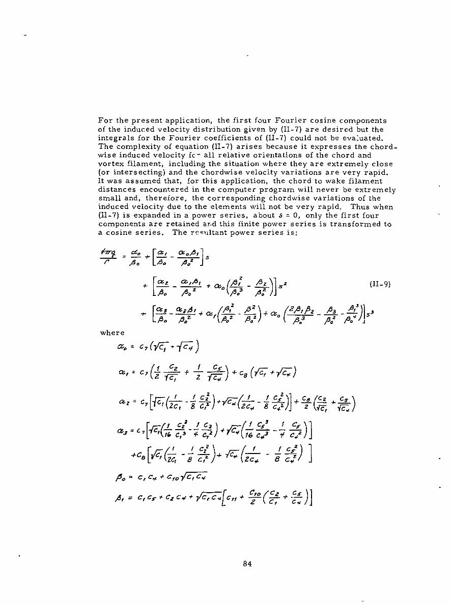
For the present application, the first four Fourier cosine componentsof the induced velocity distribution given by (11-7) are desired but theintegrals for the Fourier coefficients of (11-7) could not be evaluated.The complexity of equation (11-7) arises because it expresses the chord-wise induced velocity fc- all relative orientations of the chord andvortex filament, including the situation where they are extremely close(or intersecting) and the chordwise velocity variations are very rapid.It was assumed that, for this application, the chord to wake filamentdistances encountered in the computer program will never be extremelysmall and, therefore, the corresponding chordwise variations of theinduced velocity due to the elements will not be very rapid. Thus when(11-7) is expanded in a power series, about s = 0, only the first fourcomponents are retained ar.d this finite power series is transformed toa cosine series. The rccultant power series is:
1~ 7~ d [ C r , c zx 0 a ,
A- A2 1 ) 0.~(~~ 33)Mz' - to"= "N ( - ) ° T A: 2 --6f)o- -6'52. A 3 pZ A2
where
C;P _E- {C;('S +.)]
2, c
+C1 8 Ze,, +( ChL
84
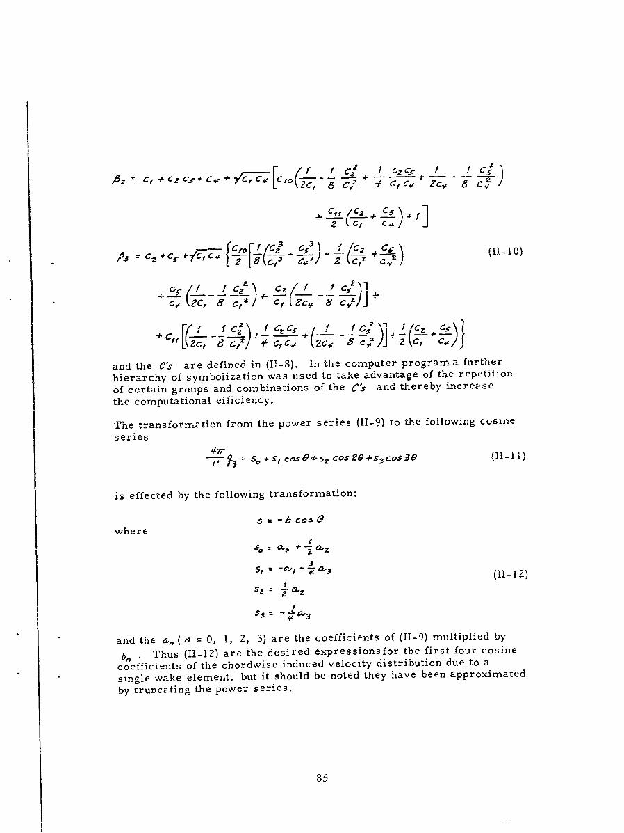
f I C Z C +of c g a c on of te [ 2 treb cr
Ef tf I ZCC?C , , + , C ' 2, [ T 6 C Zc . z C 5 2 I¢ "
the computational efficiency.
The transformation from the power series (11-9) to the following cosine
series
--7i-S 0 =S, coSOs 2 COSZO+s 3 COS30 (lI-li )
is effected by the following transformation:
4-b Cos 4
where'
. 2 - v - - .3 ( 1 1 -1 2 )
+ ~S =r -C f "3
and the , (n = 0, i, 2, 3) are the coefficients of (II-9) multiplied bybiearThus (-12) are the desired expressionsfor the first four cosinecoefficients of the chordwise induced velocity distribution due to asingle wake element, but it should be noted they have been approximatedby truascating the power series.
85
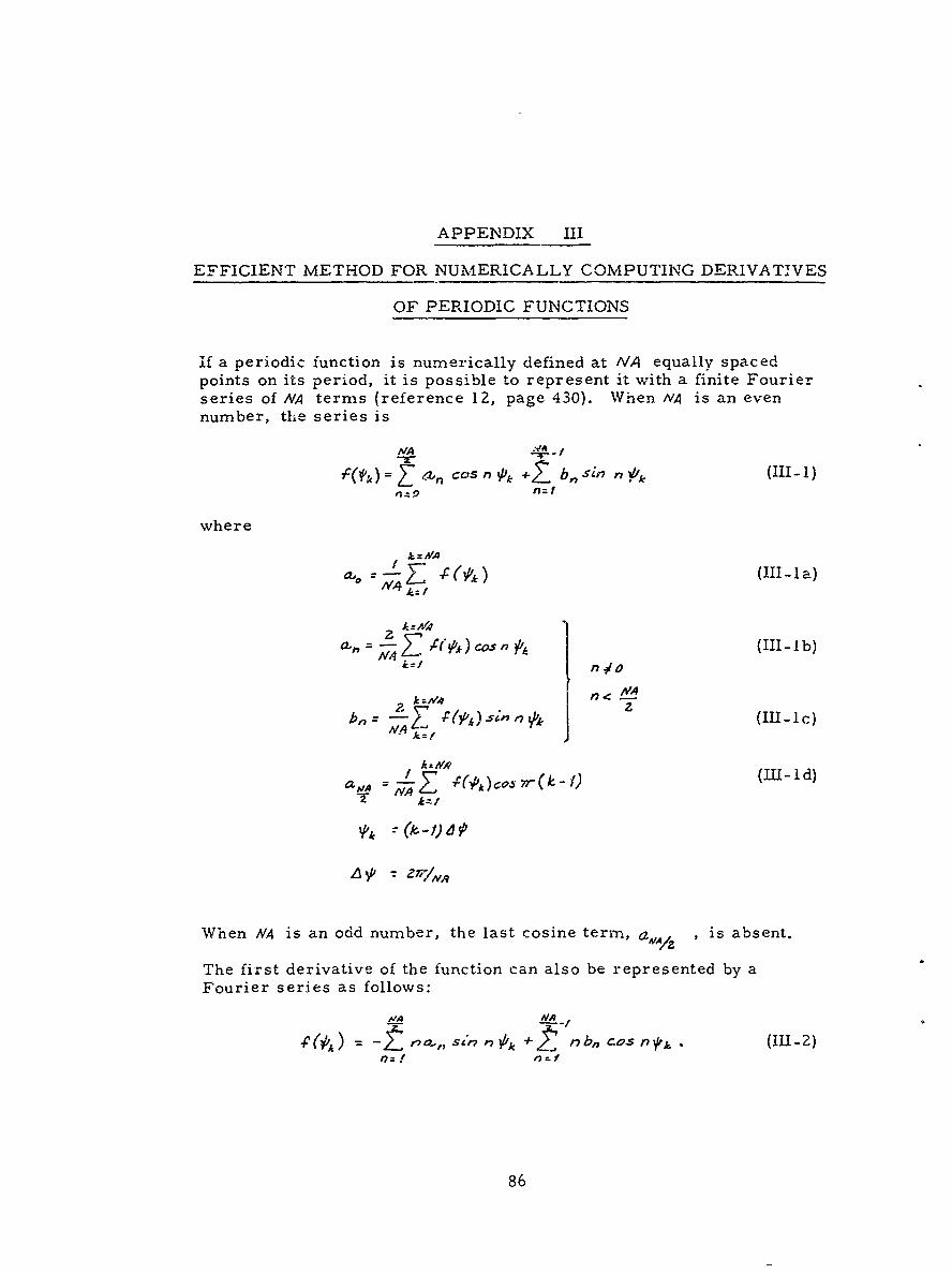
APPENDIX III
EFFICIENT METHOD FOR NUMERICALLY COMPUTING DERIVATIVES
OF PERIODIC FUNCTIONS
if a periodic function is numerically defined at IVA equally spacedpoints on its period, it is possible to represent it with a finite Fourierseries of NA terms (reference 12, page 430). When NA is an evennumber, the series is
MA MA
'C0 e2z. co's n P4. +21 b, sin n P11-
where
/A
a-' ;7 Z_, -C (ip')(! -la
a,,, = - C (SP)c. , (IlIb)
k =Mv4 n <:
I<AVA- 2 k:/
aMA T
When NA is an odd number, the last cosine term, a AmAZ is absent.
The first derivative of the function can also be represented by aFourier series as follows:
60,) aj, s in 7 Vlk j rb, c os n yk (III Z):f nut
86
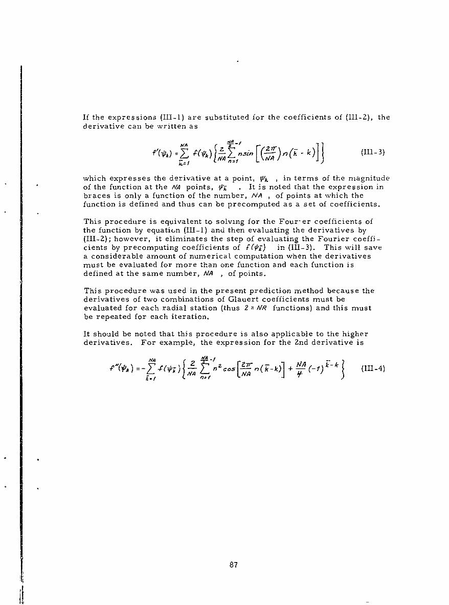
If the expressions (III-1) are substituted for the coefficients of (111-2), thederivative can be written as
MA rZn si ,2 r (111-3)f (,, : 1 ~ )
which expresses the derivative at a point, Vlk , in terms of the magnitudeof the function at the NA points, . It is noted that the expression inbraces is only a function of the number, NA , of points at which thefunction is defined and thus can be precomputed as a set of coefficients.
This procedure is equivalent to solving for the Four-er coefficients ofthe function by equation (III-1) and then evaluating the derivatives by(III-2); however, it eliminates the step of evaluating the Fourier coeffi-cients by precomputing coefficients of ( jb) in (111-3). This will save
a considerable amount of numerical computation when the derivativesmust be evaluated for more than one function and each function isdefined at the same number, NA , of points.
This procedure was used in the present prediction method because thederivatives of two combinations of Glauert coefficients must beevaluated for each radial station (thus 2 : AIR functions) and this mustbe repeated for each iteration.
It should be noted that this procedure is also applicable to the higher
derivatives. For example, the expression for the Znd derivative is
IYA MA - /
2 F-~-r, ~kl+M()-. 11IVAf L NAJ )
87
I,
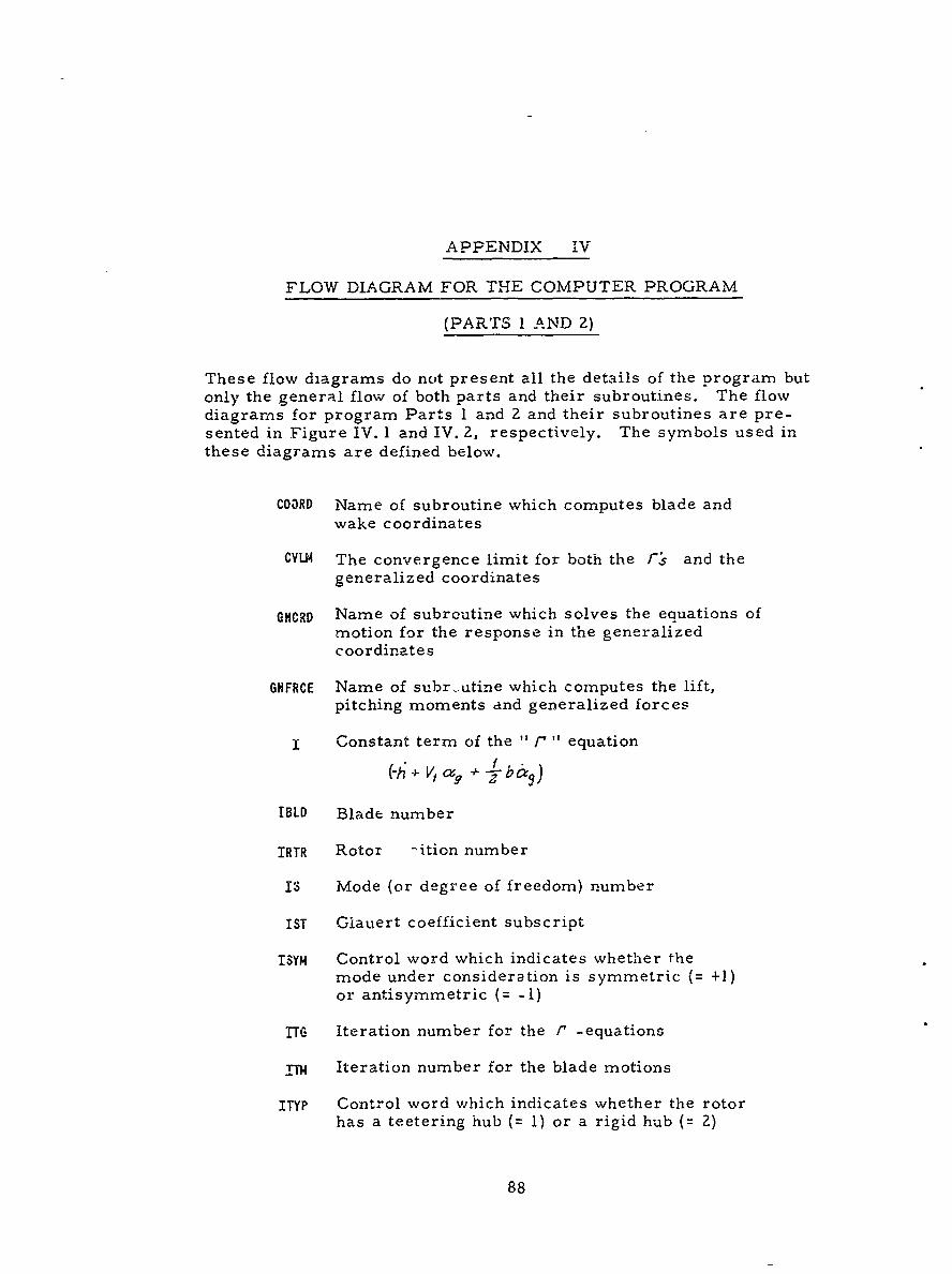
APPENDIX IV
FLOW DIAGRAM FOR THE COMPUTER PROGRAM
(PARTS 1 AND 2)
These flow diagrams do not present all the details of the program butonly the general flow of both parts and their subroutines. The flowdiagrams for program Parts 1 and 2 and their subroutines are pre-sented in Figure IV. 1 and IV. 2, respectively. The symbols used inthese diagrams are defined below.
COORD Name of subroutine which computes blade andwake coordinates
CLN The convergence limit for both the rF and thegeneralized coordinates
GNCRD Name of subroutine which solves the equations ofmotion for the response in the generalizedcoordinates
GNFRCE Name of subr-utine which computes the lift,pitching moments and generalized forces
x Constant term of the - r " equation
h+ V, (, +
IBLD Blade number
IRTR Rotor -ition number
IS Mode (or degree of freedom) number
IST Glauert coefficient subscript
ISYM Control word which indicates whether themode under consideration is symmetric (= +1)or antisymmetric (= -1)
17TG Iteration number for the r -equations
TN Iteration number for the blade motions
ITYP Control word which indicates whether the rotorhas a teetering hub (= 1) or a rigid hub (= 2)
88
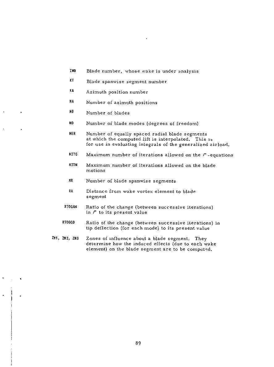
IWH Blade number, whose wake is under analysis
KT Blade spanwise segment number
KA Azi-.uth position number
NA Number of azimuth positions
HB Number of blades
ND Number of blade modes (degrees of freedom)
HER Number of equally spaced radial blade segmentsat which the computed lift is interpolated. This itfor use in evaluating integrals of the generalized airload.
NHUG Maximum number of iterations allowed on the P -equations
HITM Maximum number of iterations allowed on the blademotions
HR Number of blade spanwise segments
RA Distance from wake vortex element to bladesegment
RTOGA, Ratio of the change (between successive iterations)in P' to its present value
RTOGCD Ratio of the change (between successive iterations) intip deflection (for each mode) to its present value
ZHI, ZH2, ZN3 Zones of influence about a blade segment. Theydetermine how the induced effects (due to each wakeelement) on the blade segment are to be compated.
89
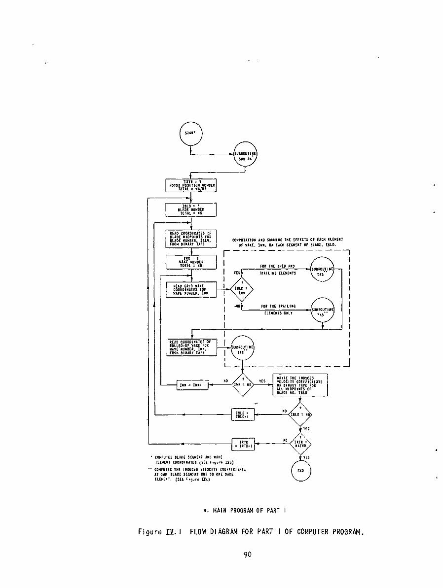
STAR'
IRTI
E A COORDIAES (SEFere1)
ATOEBLADE MIDPMINTS FU O OEkI
DLtfN . (SE ,.i E 1
t F~~~a BIAIN PRL'jOfRAME OF PART SEMNI FBAE BD
Figure~WAK NUMBEFORIGRMFRPATIO CMUE PORM
TO AL = 5 ORTH SEDAN90BR
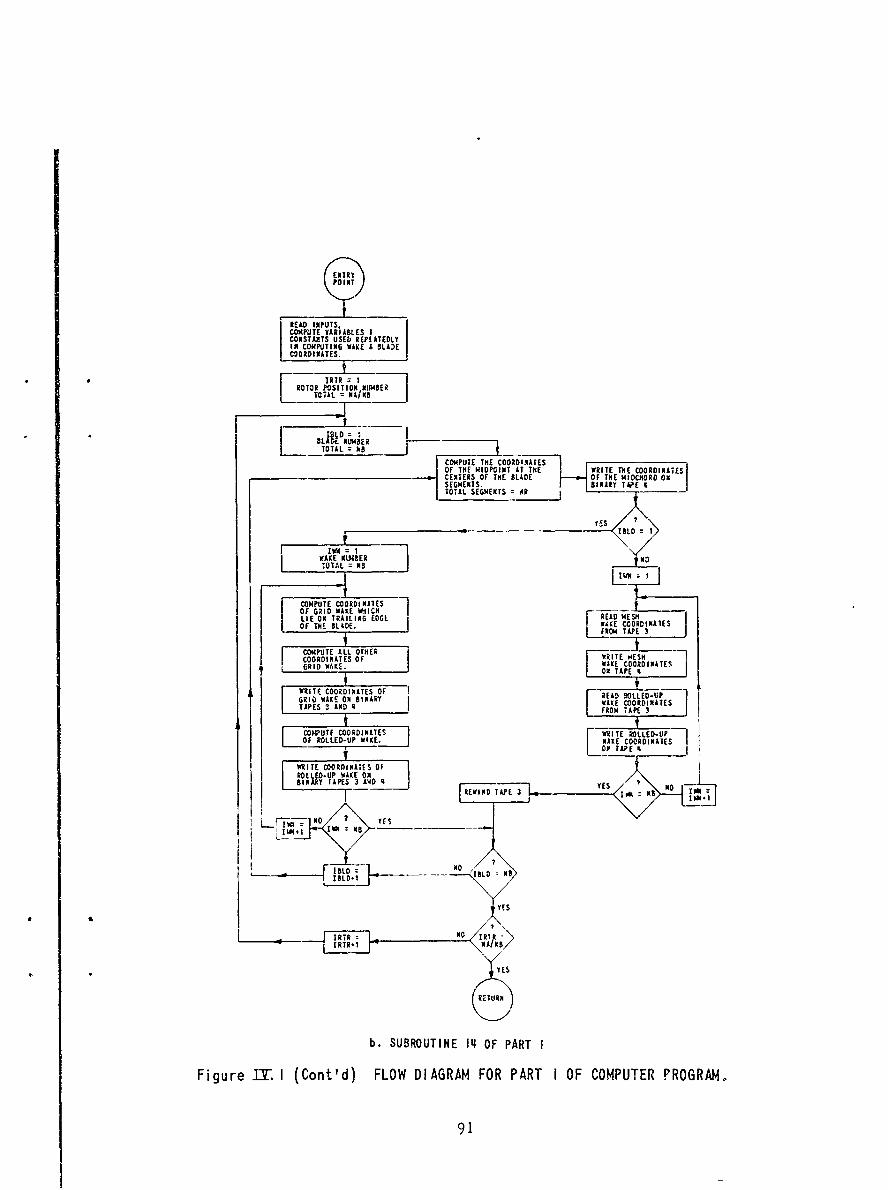
ENTRY
EAD INPUTSCO~I4PTE VARIABLES ICONSTANTS USED REPI ATEDLYIN COMPTIG WAE £ BLAECDORDIIATES.
S[ IRIR 1ROTOR PO SITI O.N; NBER
[ TOTAL = AIN
TOTALIP!hk a
COMPUTE THE COODDIATES-OF THE MIDOPIT IT TH WITE ITHE COORDINATESCE XRTERS OF THE BLADE OF THE MICHORD ONSEGME HTS. BINARY TWE |TOTAL SEGMENTS OR
I 41 :
WAKE KL3ABERTAT~L =NB
COMPUTE COORDI NAIESOF GRSD WAXE WICMLIE ON TRAILING EDGE i READ MESHOF THE BL DE. I WAKE COORDINATES
FRO4 TAPE 3
O ITE AL. OTHERCOORDINATES OF WRITE IESHIRI FAE kAKE ORD INATES
ON TAPE
tlTF COORDINATES OF lEA OGRI 0 AKE 09 BINARY READ OLLED-UPT AE OH N A WAKE COORDINATES
L FROM TAPE 3
COMPUTE COORDINATES WRITE ROLLED-UPOF ROLLED-UP WAKE. WAKE COORDINATES
ON TAPE
WRIlTE COORDINATES OFROLLEO-UP WAKE ONBINRYTAPES 3 AND REWIND TAPE 3 _ ES MB
WN4 NBBN
LFD NO YES
b. SUBROUTINE IL OF PART I
Figure Ib. I (Cont'd) FLOW DIAGRAM FOR PART I OF COMPUTER PROGRAW
91
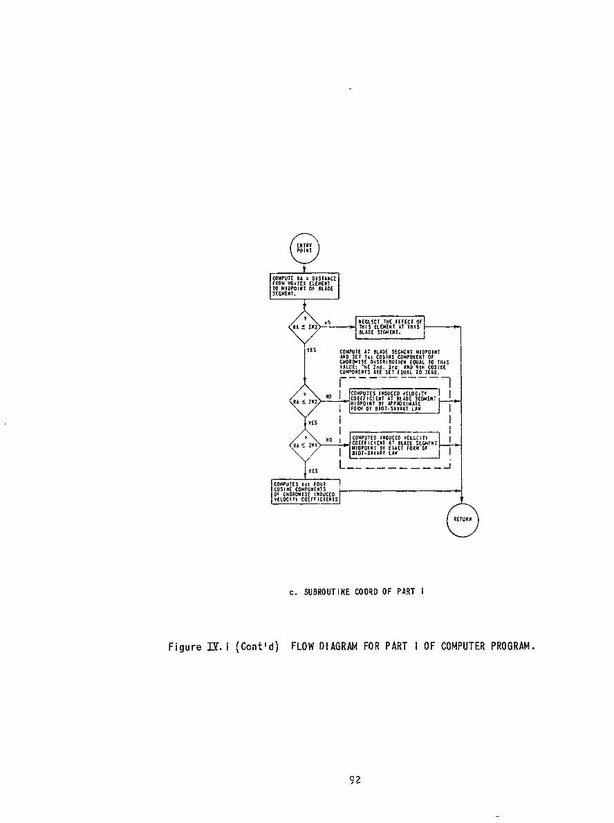
COMPUTE RA =DISTANCElFROM VORTEX ELCEETT0 MIDPOINT Ol, SLADEISEGMENT.j
? I. . ..... NEGLICT TME FFFECT O0FRA~ & 2N3 TY.I S ELEMENT AT THIS
SLDESEKET
YS COMPUTE AT. SLADE SEGMENT MIDPOINT
AN CSSIN COMPOINEC04ENTNSOCCOROISDWNUCE IITIU:XEQA OTI
VALUE:IT COEFFIC3d N D4tNCOIK
NO SURUIECOOR- IDUCOF PAT y
Figure IY I (ont'd) LOW DIA RFOREX AT LD OF OMUTR POGAM
Z;!As212 L.AT.E92""I-
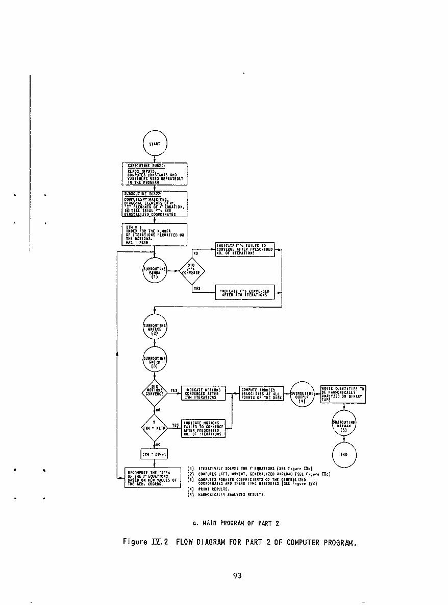
SYIT
jLB8MUTINE SUB2i:READ$ I NPUTS
COMPUTE S CO M TANTS A NDVARIABLES USED tREPEATEOLTIN THE PROGRAM
* * SUBROUTINE SUB22:COMPUTESbO MATkICES 'DIA!GONALELEMENTS 0 5r*P ELEM NTS OF r cQAfIONINITIAL T IAL I." 'DDGENEZALIZED COORDINATES
IN DER FOR TIE NUMBEROF ITERATIONS PERMITTED ONTHE NOTIO0N S.
- ~~~ ~~NO NOOFIEAIS
SUBROTIEONFACEON
(3)
MOTIONS Y ES INDICATE rOIN COPUERIDCED RT INTESOC.ONTEROE ~ ~ ~ ~ ~ E COVEGE AFE EITEATS SINUTN B A
UBINDICNYESkC
MASE ON$ Y V ES F (3) CTE OUOES OUIRCOMPUTECINDUCE ORIT THE ENERALIZETH E.COVRS. COODIATES AN VHI ELO ITOIES (LSEE slgu I JABEMRN)
*~~~~~OTU (5AAROICLYANLZEYESLS
.ITEAINS POIRNT OF PAT 2IKH D nBNR
Fiur = 2 FOW DIA GA FOHAT2AFCMUTRPORMAMN
"ERA 93
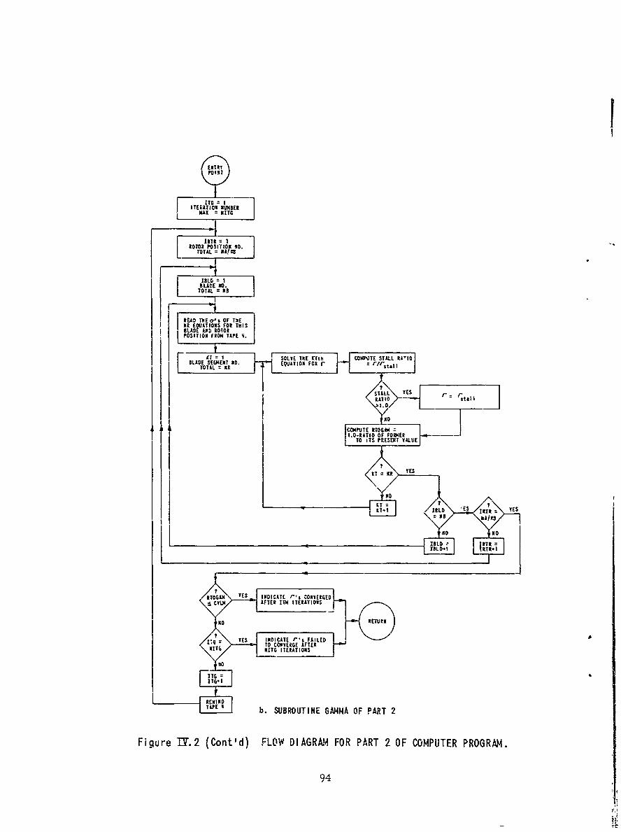
MAX =1116
toTOX PO S IDNO 10. -
IBL6 I'
TOTAL. NB-
MR E At IONSTERATIOMS
Fiur T2(Cot d FL= DIGA FOR P TA 2 F OMUERPRGRM
LADE EGMEN MD94
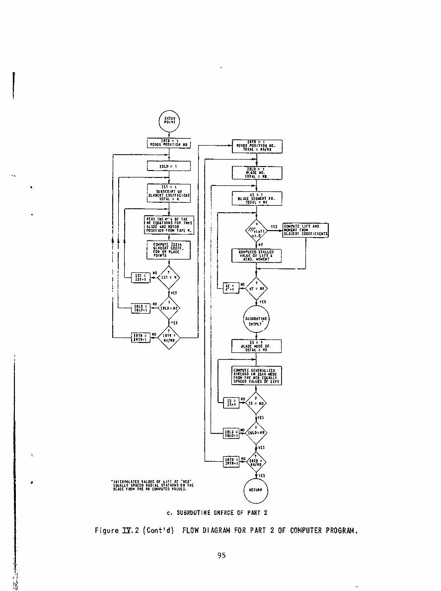
ROTOR POSITIOaN j lo R OM sITION No.
~~~-1T5 TIL = AMN
LIL:j ISLO:
1ST :SUBSCRIPT OF
6GLALIERT CO LFTFIC]IENT BLIS!IT DL TOAL ITOTAL: 2R1FREAD THN! C, OF THE
Ilt E ATIO S FOP THISPOSIT lo g F RO N TAP E 4 . MOMENW~4C T FRO M
f '.O GL&AERT COEFFICIENT
FO R LD COMPUTED STALLEDPNTS VALUE OF LI'T &
1iST= t- IT=%! IIST.I NKE=N
'YESS
SU1.OUTINE
IS
COMP OUTIEREAIEAIRLOA .N I.t He
YES UTYES
10LO 1BTLT.N
L~IT HOR=NOIT
.00
BLADE ~ ~ ~ ~ ~ aLD FROM THCOCOPTD.AUSRTR
c.IRO SUBOUIN 11FR E O R E
Figure 31Y.2SPAC DCntd FLO DIRA FOR PART O OPTRPOR
95 s,0 IS N
YE

LLDISM '10
tU 10BLADE M DE C
ALL HAborICS OF ROTOR 2 1 ROTOR-l ATSI4TCMOEBET COMPUTED ONLY ODD 11A2)IDNICS
V ILL EE COMPUIED
IIAI OIONLLL E, I HAIS S:0PUE T ERA ARL1. BBED MCOEPUO.
IN ZE 1th KMOETOALC
APN OF THE SE:
HARONCALY NALZEis NI
ADSLD THE EAINSOF MION FO THEFOUIERCFIC IENTS= I
DZIUT TPE RESPOSENINo.
LE 1THE MFJHODEOF NOTINO
AZTHEIth ODEO NO.
TOTAL = MA JYES
NA NOITINCOMPUTE TAE GENERALIZED NDSPLACEMENT ADVELOCITY
OF THlE KAth AZIMUTHPOITIO N DTEItl EP PSE
1.0-TION FOR E R IYE
ENENALIZE CORINT S- i IS NO ? INDICATE THAT
NA NO OTI OFS FOOME O N E G
TOISP ESCOMPUTEN YHESFRE
v BINDINGT MOTST
LJK NO E
YES COMPFEUTE THEFORE
IS MO v ENDING MOMENT
S N Y E C H7 ST O R E
6RETUR N
d. SUBROUTINE GNCRD OF PART 2
Figure 11Y.2 (Ccnt~d) FLOW DIAGRAM FOR PART 2 OF COMPUTER PROGRAM.
96
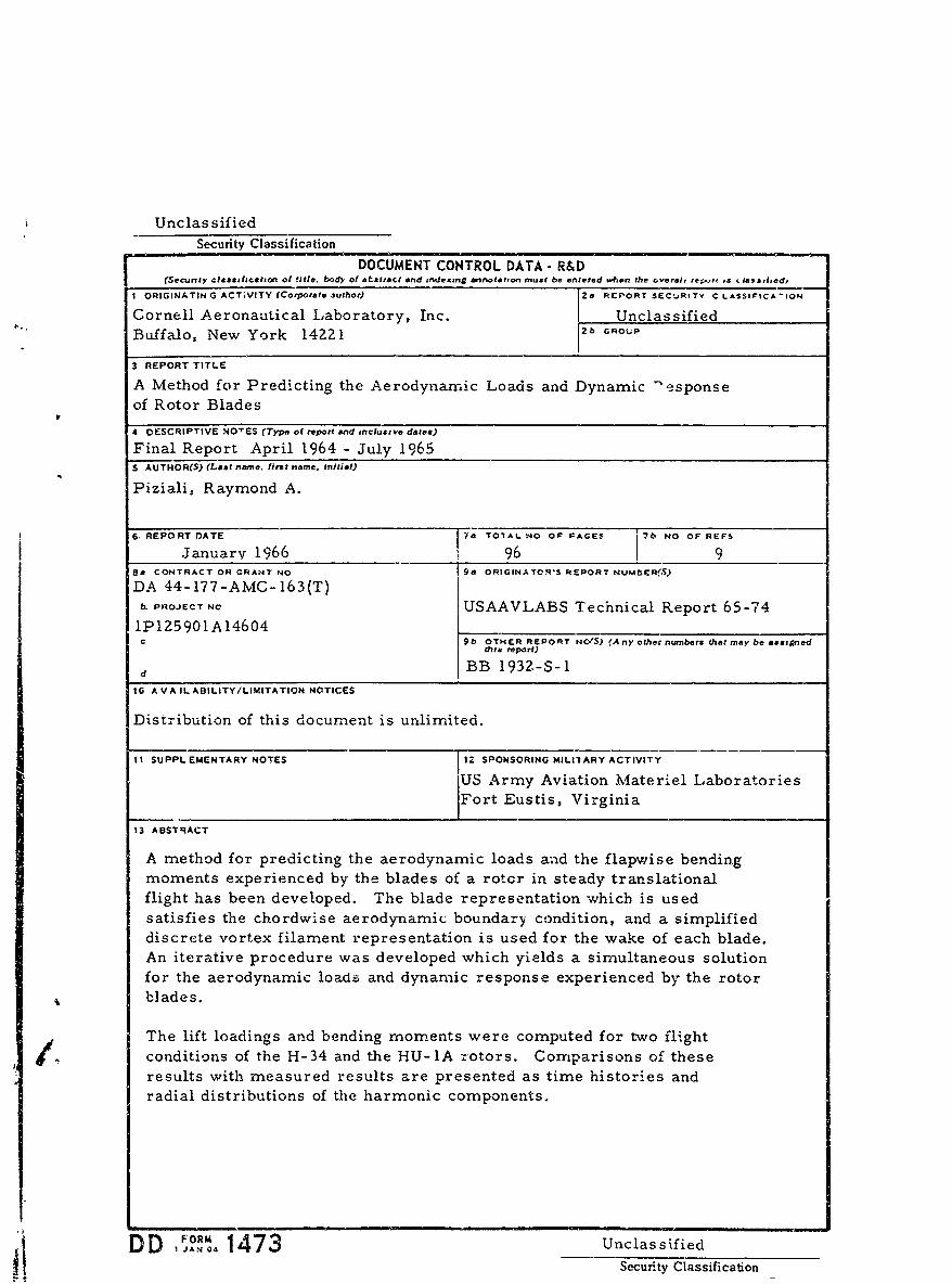
Unclas sifiedSecurity Classification
DOCUMENT CONTROL DATA- R&D(Secunty clas.ificition of title, body of abstract and indexing annotation must be entered w.hen the overaig re;..t is . ias.,ied,
I ORIGINATIN G ACTVITY (Corporate 3uthor) 120 RCORT SECjRI TY C LASSIFICA 10N
Cornell Aeronautical Laboratory, Inc.I UnclassifiedBuffalo, New York 14221 1 2b GROUP
3 REPORT TITLE
A Method for Predicting the Aerodynamic Loads and Dynamic "esponse
of Rotor Blades
4 DESCRIPTIVE NO'ES (Typo of report and inclusive dates)
Final Report April 1964 - July 1965S AUTHOR(S) (LAs, name. first name. Initial)
Piziali, Raymond A.
6. REPORTDATE ia TOIAL SO OF FAGES 7b NO OF REFS
Januarv 1966 96 1 9Sa CONTRACT OR GRANT NO 9a ORIGINAtTOWS REPORT NUMESERfS)
DA 44- 177-AMC-163(T)PROJECT NO USAAVLABS Technical Report 65-74
1P125901AI4604C 9b OTHER REPORT NO'S) (Any other numbers that may be asstpned
thib report)
d BB 1932.-S-I10 AV AILABILITY/LIMITATION NOTICES
Distribution of this document is unlimited.
I I SUPPLEMENTARY NOTES 112 SPONSORING MILrIARY ACTIVITY
Army Aviation Materiel LaboratoriesFort Eustis, Virginia
13 ABSTRACT
A method for predicting the aerodynamic loads and the flapwise bendingmoments experienced by the blades of a rotcr in steady translationalflight has been developed. The blade representation which is usedsatisfies the chordwise aerodynamic boundary condition, and a simplified
discrete vortex filament representation is used for the wake of each blade.An iterative procedure was developed which yields a simultaneous solutionfor the aerodynamic loads and dynamic response experienced by the rotorblades.
The lift loadings and bending moments were computed for two flight.co dconditions of the H-34 and the HU-lA rotors. Comparisons of these
results with measured results are presented as time histories andradial distributions of the harmonic components.
DD 1473 UnclassifiedSecurity Classification
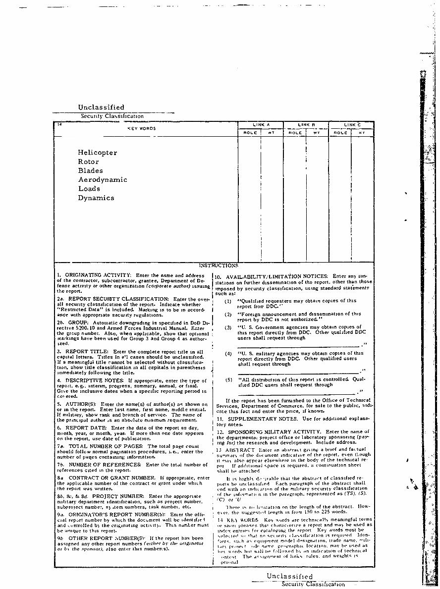
Unclas sifiedSecurity Classification
14 LINK A LINK S LINK CKEY WORDS -____ -
T RO T ROLE wr
Helicopter
RotorBladesAerodynamicLoadsDynamics
INSTRUCTIONS
1. ORIGINATING ACTIVITY: Enter the name and address 110. AVAILABILITY/LIMITATION NOTICES: Enter any ir-of the contractor, subcontractor, grantee. Department of De- ttions on further dissemination of the report, other than thosetense activity or other organization (corporate author) issuing *mposed by security classification, ustng standard statement-the report. [such at:
2a. REPORT SECURITY CLASSIFICATION: Enter the over- (1) "Qual-fied requesters may obtain copies of thisall security classification of the report. Indicate whether"Restricted Data" is included. Marking is to be in accord- report from DDc.hance with appropriate security regulations. (2) "Foreign announcement and dissemination of this
report by DDC is not authorized."2b. GROUP: Automatic downgrading is specified in DoD Di- rrective 5200. 10 and Armed Fcrces Industrial Manual. Enter (3) "U. S. Government agencies may obtain copies ofthe group number. Also, when applicable, show that optional this report directly from DDC. Other qualified DDCmarkings have been used for Group 3 and Group 4 as author- users shall request throughized.
3. REPORT TITLE: Enter the complete report title in all (4) "U. S. military agencies may obtain copies of thiscapital letters. Titles In all cases should be unclassified, report directly from DDC. Other qualified usersIf a meaningful title rannot be selected without classifica- shall request throughtion, show title classification in all cepitals in parenthesis 1,immediate!y following the title.I
4. DESCRIPTIVE NOTES If sppropriate, enter the type of (5) "All distribution of this report is controlled. Qual-repoit, e.g.. interim, progress, summary, annual, or final. ified DDC users shall request throughGive the inclusive dates when a specific reporting period is.col ered.
If the report has been furnished to the Office of Technica5. AUTHOR(S): Enter the name(s) of author(s) as shown on Services, Department of Commerce. for sale to the public, mdi°or in thQ report. Enter last name, first name, middle initial. cate this fact and enter the price, if known.If military, show rank and branch of service. The name ofthe principal author is an absolute minimum requirement. 11. SUPPLEMENTARY NOTES. Use for additional explana-
6. REPORT DATE. Enter the date of the report as day, tory notes.
month, year, or month, year. If more than one date appears 12. SPONSORING MILITARY ACTIVITY. Enter the name ofon the report, use date of publication, the departmentaL project office or labcratory sponsoring (pay-
ing for) the research and develcpment. Include address.7a. TOTrAL NUMBER OF PAGES: The total page count
should follow normal pagination procedures, i.e., enter the 13 AI3SI RACT Enter an abstract g in a brief and fautualnumber of pages containing information. summar', of the document indicative of the report. even tLough
it ma', also arpear elsewhere in the body of the technical re-7b. NUMBER OF REFERENCES- Enter the total number of pot If additional %pace is required, a continuation sheetreferences cited in the report. ;hall be atta(hed8a CONTRACT OR GRANT NUMBER. If appropriate, enter It is highl, .':table that the abstract of classified re-the applicable number of the contract or grant under which ports be unclassified Each paragraph of the abstract shallthe report was written. end with an indication of the military security classification a
8b, 8c, & 8d. PROJECT NUMBER: Enter the appropriate of the inforrrati n in the paragraph, represented as (TS), (S).
military department identification, such as project number, (C) or'Usubproject number, sl ,tem numbers, task numbei, etc. lhere Is n,, limitation on the length of the abstract. |low-9a. ORIGINATOR'S REPORT NUMBER(S): Enter the offi- e'.er, the suggeste d length is from 150 to 225 words.
cial report number by which the dociument will be identifiel 14 KEN %,tRDS Ke, %hords are technical! meaningful termsand entrolled by the criginating activity. This numLer must or short phrases that characertze a report and may be used asbe unique to this report. inde- entries for cataloging the report Key vords must be
9b OTHER REPORT NUMBER(S1" If the report has been .elected s, 'hat roe ,ecurit, (lahsification is requied Iden-assigned any other report numbers (either by the oriinator tlers. sukh as equipment model d-signation, trade name, -iII-or b the ,sponsor), also enter this numberts). t.,rN pri.e t dh- name geopraphi, location. may be used as
r,, wOrd, but %%ill 6e' follo.ed b% .n indication of technial
ontest The a, imn,'nent of links rules, and weivhts Ispt I,,nalI
Unclassified
--secur iV'C Tassi1 ,Icat ion