Embed Size (px)
Citation preview

White Paper:
UUssaaggee ooff DD66TT--4444LL // DD66TT--88LL TThheerrmmaall sseennssoorr

White Paper : D6T-44L/D6T-8L
Copyright © 2013 OMRON Corporation. All Rights Reserved. 2
1. Outline This application note provides a supplement to the data sheet for D6T series non-contact
temperature sensor – by adding special instructions and usage information.
*Please see Omron’s website for the most current datasheet.
2. Structure The D6T series sensors are made up of a cap with silicon
lens, MEMS thermopile sensor chips, and dedicated analog
circuit and a logic circuit for converting to a digital temperature
value on a single board through one connector. Fig1.1 Module outline ( Reference )
3. Dimensions Please refer to the data sheet for complete dimension details. The height of the lens on the
D6T-44L and D6T-8L are different, but both feature a small PCB (14mm x 18mm). The module
also has a retention area and holes usable for proper alignment . For connector details please see
Section 6. 4. Operating principle
An outline of the basic measuring operation is as
follows:.
・ The silicon lens collects radiated heat (far-infrared ray)
emitted from an object onto the thermopile sensor in the
module.
・ The radiated heat (far-infrared ray) produces an
electromotive force on the thermopile sensor.
・ The analog circuit calculates the temperature of an object
by using the electromotive force value and a measured
temperature value inside the module.
・ The measured value is outputted through an I2C bus. Fig4.1 Module construction
(Inside)
Thermopile sensor
Silicon lens
(back side)

White Paper : D6T-44L/D6T-8L
Copyright © 2013 OMRON Corporation. All Rights Reserved. 3
5. Features The non-contact temperature sensor measures the surface temperature of an object. D6T-44L-06
and D6T-8L-06 have sensor chip arrays of 16 channels (4x4) and 8 channels (1x8) respectively. By
mounting the signal processing circuit closely to the sensor chip, a low noise temperature
measurement is realized.
The module can also be used for detecting the presence of human beings. Omron’s non-contact
temperature sensor can solve the shortcomings of a conventional pyroelectric sensor, which cannot
catch the signal of a stationary person because the sensor detects the change of signal [in principle].
Moreover, Omron’s non-contact temperature sensor keeps detecting the far-infrared ray of an
object, while the pyroelectric models do not.
(a) Pyroelectric sensor output (b)Non-contact temperature sensor output
Fig 5.1 Difference between pyroelectric and non-contact temperature sensors
The non-contact temperature sensor achieves its sensitivity characteristic for an object view
angle by using a silicon lens. FOV (Field Of View) – an indication of view angle – is generally
specified as an area angle of 50% for maximum sensitivity.

White Paper : D6T-44L/D6T-8L
Copyright © 2013 OMRON Corporation. All Rights Reserved. 4
(a) D6T-44L-06 FOV(16ch) image (b)FOV and XY axis for a element
Fig 5.2 Sensitivity characteristics: FOV Image
Please note that the sensitivity area is wider than the FOV specified area. When an object to be
measured is smaller than the sensitivity area, the background temperature effects the
measurements.
Though Omron’s D6T sensor corrects a temperature measurement value by using a
reference heat source (blackbody furnace), the measurement’s value is influenced by the
emissivity of the specific material of the object to be measured, and the surface shape of the
occupant relative to the sensitivity area.
Distance near >>>>>> Far
IR
IRIR
IR
Area1 FOV
Area2 FOV
Fig 5.3 Changing factor of measurement by distance
Note: The occupied area in FOV becomes smaller with increasing distance
and the background temperature prevails.
FOV
50% for maximum
sensitivity

White Paper : D6T-44L/D6T-8L
Copyright © 2013 OMRON Corporation. All Rights Reserved. 5
In cases where a D6T sensor is used for detecting human beings, the application will be
limited to close range when the detection programming scheme only judges by temperature value.
To extend the detection distance, improvements to the judgment accuracy can be made via
software programming, considering time change, heat source location and human being movement.
6. Usage
6.1 Connector
D6T-44L-06 D6T-8L-06
Fig 6.1 Connector outline
Connector pin
Table 6.1 Pin
1 GND Ground
2 VCC Power source (5V +/-10%)
3 SDA I2C(5V) Data line
4 SCL I2C(5V) Clock line
One Connector (used inside sensor) : JST p/n SM04B-GHS-TB
To connect to the system, use the following four-pin mating connector.
Contact : JST p/n SSHL-002T-P0.2 (4pcs).
Housing : JST p/n GHR-04V-S
The difference in appearance is due to the varying height of the lens. For detailed dimensions,
please refer to the data sheet.

White Paper : D6T-44L/D6T-8L
Copyright © 2013 OMRON Corporation. All Rights Reserved. 6
6.2 Electrical connection
Case 1: Direct connection. The voltage of MCU Power source is 5V.
D6T
VCC
SDA
SCL
GND
VDD5
SDA
SCL
GND
MCU
R R
Power5V
GND
Fig 6.2(a) Direct connection
Case 2: Direct connection. 3V MCU (5V-tolerant I2C port)
D6T
VCC
SDA
SCL
GND
VDD
SDA
SCL
GND
MCU R R
5V3V
Fig 6.2(b) 5V-tolerant
Case 3: Using I2C level translating IC.
(not 5V-tolerant, other LV-devices exist on the same I2C-bus)
D6T
VCC
SDA
SCL
GND
VDD
SDA
SCL
GND
MCU
R R
I2CLevel
Translating
R R
5V
Ex. PCA9517
Fig 6.2(c) Using I2C level translating IC

White Paper : D6T-44L/D6T-8L
Copyright © 2013 OMRON Corporation. All Rights Reserved. 7
Pull-Up Resistor :
Impedance value is decided by user. (see I2C[100kHz] specification note.)
(Most case : About 3k to 10k ohm)
Case 4: Software I2C. using Bi-directional Open Drain GPIO ports.
(MCU has no I2C module inside.)
Note: Wait routine for Clock-Stretching is required – to be prepared by the user.
MCU
R
FFOpenDrain
SDA
SCL
R
FFOpenDrain
SDA
SCL
Fig6.2(d) Using GPIO-ports
Case5: Using I2C bus switch IC. Ex. PCA9545(4ch) , PCA9548(8ch)
(multiple D6T sensors)
D6T
VCC
SDA
SCL
GND
VDD
SDA
SCL
GND
MCU
R R
I2C busswitch
R R
5V
R R
D6T
VCC
SDA
SCL
GND
:
SDA 0
SCL 0
SDA x
SCL x
SDA 1
SCL 1
SDA 2
SCL 2
Fig6.2(e) Using I2C bus switch IC

White Paper : D6T-44L/D6T-8L
Copyright © 2013 OMRON Corporation. All Rights Reserved. 8
6.3 I2C port setting
Table 6.2 I2C port parameters
Device Address 7bit : 0001_010b
8bit (with R/W bit) Read : 15h , Write : 14h
Data bit width 8bit (MSB-first)
Clock Frequency max 100kHz
Control for Clock-stretching On (Auto waiting) *see Section 6.6
Start Address(W)
Command(4Ch)
RepeatStart
Address(R)
PTAT(Lo)
PTAT(Hi)
P0(Lo)
P0(Hi)
P14(Lo)
P14(Hi)
P15(Lo)
P15(Hi)
PEC StopP1 to P13(Lo,Hi)
Output data : 35 bytes (a) 16ch (D6T-44L)
Start Address(W)
Command(4Ch)
RepeatStart
Address(R)
PTAT(Lo)
PTAT(Hi)
P0(Lo)
P0(Hi)
P6(Lo)
P6(Hi)
P7(Lo)
P7(Hi)
PEC StopP1 to P5(Lo,Hi)
Output data : 19 bytes (b) 8ch (D6T-8L)
Fig 6.3 I2C port data chart
Table 6.3 Output data format
PTAT The value of the reference temperature, inside the sensor module.
Temperature data (PTAT&Pn) is 16bit-width, singed, 10 times value of degC.
Example : 12.7 °C = 007Fh(127) , 25.8 °C = 0102Fh(258)
P0 to P15
(D6T-44L)
P0 to P7
(D6T-8L)
Measured value. Pixel order is below.
PEC
Packet error check code. Based on the “SM bus” specification.
White Paper : D6T-44L/D6T-8L
Copyright © 2013 OMRON Corporation. All Rights Reserved. 9
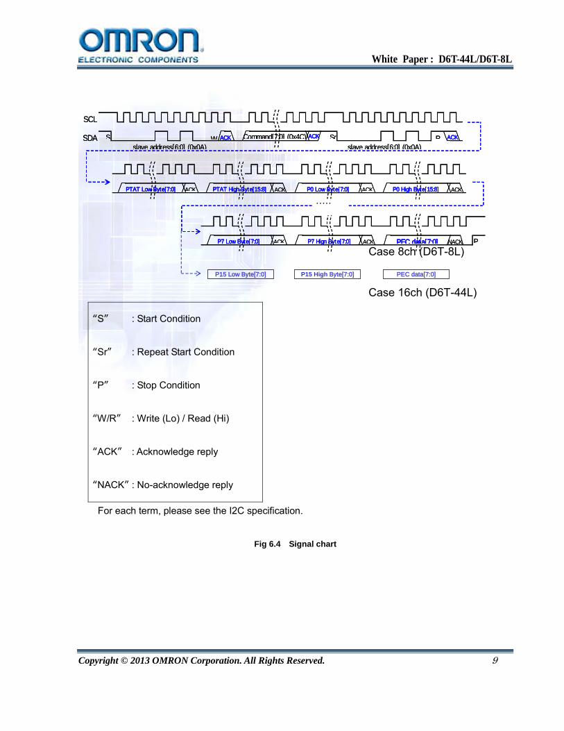
SCL
SDA S ACK ACKSrslave address[6:0] (0x0A)
ACKW Command[7:0] (0x4C) Rslave address[6:0] (0x0A)
ACKACKPTAT Low Byte[7:0] ACKACKPTAT High Byte[15:8] P0 Low Byte[7:0] P0 High Byte[15:8]
ACKACK NACKPEC data[7:0] PP7 Low Byte[7:0] P7 Hign Byte[7:0]
・・・・・
SCL
SDA S ACK ACKSrslave address[6:0] (0x0A)
ACKW Command[7:0] (0x4C) Rslave address[6:0] (0x0A)
ACKACKPTAT Low Byte[7:0] ACKACKPTAT High Byte[15:8] P0 Low Byte[7:0] P0 High Byte[15:8]
ACKACK NACKPEC data[7:0] PP7 Low Byte[7:0] P7 Hign Byte[7:0]
・・・・・
P15 Low Byte[7:0]
Case 8ch (D6T-8L)
Case 16ch (D6T-44L)
P15 High Byte[7:0] PEC data[7:0]
“S” : Start Condition
“Sr” : Repeat Start Condition
“P” : Stop Condition
“W/R” : Write (Lo) / Read (Hi)
“ACK” : Acknowledge reply
“NACK” : No-acknowledge reply
For each term, please see the I2C specification.
Fig 6.4 Signal chart

White Paper : D6T-44L/D6T-8L
Copyright © 2013 OMRON Corporation. All Rights Reserved. 10
6.4 Example Getting the measurement value. (16ch : D6T-44L) // I2C communication functions
extern void I2C_start();
extern void I2C_repeatstart();
extern void I2C_stop();
extern void I2C_send1( char addr8 , char cmd );
extern void I2C_getx( char addr8 , char buff[] , int length );
extern int D6T_checkPEC( char buf , int pPEC );
// Global var.
extern char readbuff[35];
extern int tPTAT;
extern int tP[16];
extern int tPEC;
int D6T_getvalue()
{
I2C_start();
I2C_send1( 0x14 , 0x4C ); // 14h = { 0Ah(Addr7) : Write(0b) }
I2C_repeatstart();
I2C_getx( 0x15 , readbuff , 35 ); // 15h = { 0Ah(Addr7):Read },35 = 2*(1+16)+1
I2C_stop();
If(!D6T_checkPEC(readbuff,34)){
return -1; // error
}
tPTAT = 256*readbuff[1] + readbuff[0];
tP[0] = 256*readbuff[3] + readbuff[2];
tP[1] = 256*readbuff[5] + readbuff[4];
tP[2] = 256*readbuff[7] + readbuff[6];
tP[3] = 256*readbuff[9] + readbuff[8];
tP[4] = 256*readbuff[11] + readbuff[10];
tP[5] = 256*readbuff[13] + readbuff[12];
tP[6] = 256*readbuff[15] + readbuff[14];
tP[7] = 256*readbuff[17] + readbuff[16];
tP[8] = 256*readbuff[19] + readbuff[18];
tP[9] = 256*readbuff[21] + readbuff[20];
tP[10] = 256*readbuff[23] + readbuff[22];
tP[11] = 256*readbuff[25] + readbuff[24];
tP[12] = 256*readbuff[27] + readbuff[26];
tP[13] = 256*readbuff[29] + readbuff[28];
tP[14] = 256*readbuff[31] + readbuff[30];
tP[15] = 256*readbuff[33] + readbuff[32];
tPEC = readbuff[34];
return 1;
}
measure()
{
n = 0;
do{
status = D6T_getvalue();
n++;
}while(status < 0 && n < LOOPLIMIT);
If(status < 0){
// error operation.
}
printf(“ %d, %d,%d,%d,%d,%d,%d,%d,%d ,%d,%d,%d,%d,%d,%d,%d,%d ,%d\n” ,
tPTAT,tP[0],tP[1],tP[2],tP[3],tP[4],tP[5],tP[6],tP[7]
,tP[8],tP[9],tP[10],tP[11],tP[12],tP[13],tP[14],tP[15],tPEC);
White Paper : D6T-44L/D6T-8L
Copyright © 2013 OMRON Corporation. All Rights Reserved. 11
}
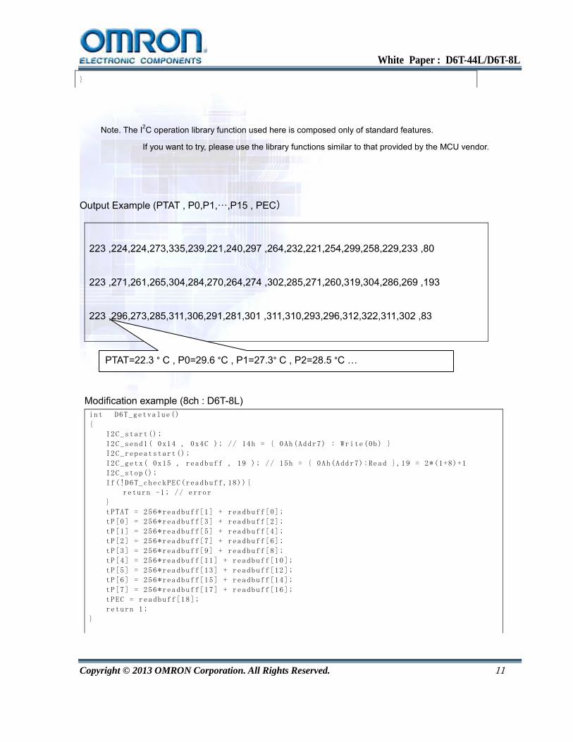
Note. The I2C operation library function used here is composed only of standard features.
If you want to try, please use the library functions similar to that provided by the MCU vendor.
Output Example (PTAT , P0,P1,…,P15 , PEC)
223 ,224,224,273,335,239,221,240,297 ,264,232,221,254,299,258,229,233 ,80
223 ,271,261,265,304,284,270,264,274 ,302,285,271,260,319,304,286,269 ,193
223 ,296,273,285,311,306,291,281,301 ,311,310,293,296,312,322,311,302 ,83
Modification example (8ch : D6T-8L) int D6T_getvalue()
{
I2C_start();
I2C_send1( 0x14 , 0x4C ); // 14h = { 0Ah(Addr7) : Write(0b) }
I2C_repeatstart();
I2C_getx( 0x15 , readbuff , 19 ); // 15h = { 0Ah(Addr7):Read },19 = 2*(1+8)+1
I2C_stop();
If(!D6T_checkPEC(readbuff,18)){
return -1; // error
}
tPTAT = 256*readbuff[1] + readbuff[0];
tP[0] = 256*readbuff[3] + readbuff[2];
tP[1] = 256*readbuff[5] + readbuff[4];
tP[2] = 256*readbuff[7] + readbuff[6];
tP[3] = 256*readbuff[9] + readbuff[8];
tP[4] = 256*readbuff[11] + readbuff[10];
tP[5] = 256*readbuff[13] + readbuff[12];
tP[6] = 256*readbuff[15] + readbuff[14];
tP[7] = 256*readbuff[17] + readbuff[16];
tPEC = readbuff[18];
return 1;
}
PTAT=22.3 ° C , P0=29.6 °C , P1=27.3° C , P2=28.5 °C …

White Paper : D6T-44L/D6T-8L
Copyright © 2013 OMRON Corporation. All Rights Reserved. 12
Note. This example represents a single measurement run.
This sensor repeats the operation for each of the data measurements and updates within 250ms.
Therefore, you will be able to retrieve new data about 4 times per second.
It is not possible for the user to control the measurement timing.
6.5 PEC check routine Example
PEC is the data used for the CRC-8 error checking method; it is then appended to the end of the
communication output. It allows you to detect communication failures effectively and improve the
reliability of the data. (For more information, please refer to the SMBus specification) unsigned char calc_crc( unsigned char data )
{
int index;
unsigned char temp;
for(index=0;index<8;index++){
temp = data;
data <<= 1;
if(temp & 0x80) data ^= 0x07;
}
return data;
}
int D6T_checkPEC( char buf , int pPEC );
{
unsigned char crc;
int i;
crc = calc_crc( 0x14 );
crc = calc_crc( 0x4C ^ crc );
crc = calc_crc( 0x15 ^ crc );
for(i=0;i<pPEC;i++){
crc = calc_crc( readbuff[i] ^ crc );
}
return (crc == readbuff[pPEC]);
}
Other case : Using Stop-Start condition without Repeat Start Condition, int D6T_checkPEC( char buf , int pPEC );
{
unsigned char crc;
int i;
crc = calc_crc( 0x15 );
for(i=0;i<pPEC;i++){
crc = calc_crc( readbuff[i] ^ crc );
}
return (crc == readbuff[pPEC]);
}
6.6 Detect routine of wait status (Clock-stretching)
Our sensor may require a wait request of the master. On the master side, it is necessary to deal with

White Paper : D6T-44L/D6T-8L
Copyright © 2013 OMRON Corporation. All Rights Reserved. 13
this wait process. In many I2C modules in the MCU, there is a feature that can do this automatically.
However, if using the I2C software library, the user may have to deal with this wait process manually.
D6TSDA
SCL
SDA
SCLMCU D6T
SDA
SCL
SDA
SCLMCU
Wait request Wait sequence
I2C Master I2C Slave(D6T)
a) SCL drive to Lo for Ack. Checking SCL status.(Lo)
(Fixed wait)
c) SCL output change to Hi-Z.
SCL I/O mode change to Input
d) Checking SCL status.(Hi)
Checking …
b) SCL drive to Lo for Wait.
Wait ...
:
:
:
Wait finish
e) SCL output change to Hi-Z.
f) Finish Detected.
SCL I/O mode change to Output
g) Next operation.
SCL
a)
b)
c)
d)
e)
f)
g)
Master drive SCL to Lo.
Slave drive SCL to Lo.
Checking SCL
6.7 Temperature range
A: D6T-44L-06/D6T-8L-06 Recommended detection range.
B: Maximum ratings.
C: Ability range (out of ratings, for reference)

White Paper : D6T-44L/D6T-8L
Copyright © 2013 OMRON Corporation. All Rights Reserved. 14
- 10
0
10
20
30
40
50
60
70
80
90
- 20 - 10 0 10 20 30 40 50 60 70 80 90 100Object temperature
Refe
renc
e te
mpe
ratu
re (P
TAT
inside
sen
sor m
odule
)
SaturateArea
SaturateArea
Fig 6.5 Temperature detection range
The temperature range of some of the electronic components is from 0 to 85° C, however, the
operating temperature range of the module is limited to 0 to 50 ° C with a detection range as shown in
the above diagram, figure 6.5. Note: Temperature range is subject to change, please confirm with the
latest product specification information.
A B C

White Paper : D6T-44L/D6T-8L
Copyright © 2013 OMRON Corporation. All Rights Reserved. 15
6.8 Cover Material
If you opt to put a cover over the sensor, carefully consider the performance of the material in
regards to how well it passes through radiant heat. High-density polyethylene (HDPE, grade far
infrared transmission) is a good cover material option. If the cover is thick, the transmittance
decreases. It is best to use as thin a cover as possible to keep a minimal impact on detection
performance. The internal sensors can then show through. (as shown in the example pictured
below).
None cover HDPE( t0.7 )
54.9%
HDPE( t0.5 ) HDPE( t0.3 )
60.1%
71.5%
100%
Fig 6.6 HDPE thickness vs. Transmittance (reference)

White Paper : D6T-44L/D6T-8L
Copyright © 2013 OMRON Corporation. All Rights Reserved. 16
7. FAQ
Question Can the field of view (FOV) angle be increased?
Answer No. OMRON set the FOV in consideration of the constraints imposed by the
thickness and refractive index of the silicon lens. Measurement distance is
reduced as the FOV of one element increases. Therefore, we can not simply
widen the viewing angle. A good way to measure a wide range, is to install
multiple sensors, or mount the senor on a movable/rotating base .
Question Are there any effects on an infrared remote controller?
Answer No. The silicon lens we are using will not pass through most near-infrared and
visible light below 1.2 [μm] wavelength. Therefore, it does not affect the infrared
signal of the remote controller. The far infrared rays that are emitted as radiant
heat are about 4 to 14 [μm].
Question Is it possible to distinguish between humans, animals, and appliances?
Answer No. In the non-contact temperature module, you can only acquire surface
temperature measurement data. Different objects of the same temperature will
read the same. Further discrimination must be based on the behavior of the
measured data to distinguish the object by software on the user side. By
developing software designed with your specific application in mind, the
determination accuracy may possibly be improved.
Question What is the distance range that can detect the presence of people?
Answer This is greatly affected by the decision performance and software installation
conditions. It is also affected by the size of the object to be measured and the area
of the FOV per element. A rough guideline distance is about 5 to 6 meters.
Question Can the power consumption be reduced?
Answer No. The D6T thermal sensor does not have a power saving mode. Therefore, in
order to reduce power consumption it is necessary to shut off the power.
Question Is there a sensor that can operate on a supply voltage of 3[V]?
Is there an I2C slave address that I can change?
Answer No. The D6T thermal sensor not support them.

White Paper : D6T-44L/D6T-8L
Copyright © 2013 OMRON Corporation. All Rights Reserved. 17
8. Terms
Thermopile
Thermal sensors utilize the Seebeck effect in which thermoelectric force is generated due to the
temperature difference at the contact points between two different kinds of metal. A thermopile is
created by serially connecting thermocouples. By creating hot junctions on highly heat-resistant
dielectric membranes, and cold junctions on highly heat-conductive silicon, it is possible to achieve
high-speed response and high-energy conversion efficiency.
NETD
Noise Equivalent Temperature Difference.
An indication of the amount of noise that is expressed as a temperature. It becomes a measure of
the minimum value of the change in the measured temperature that can be determined. It is
sometimes referred to as temperature resolution.
FOV
Field of View. FOV range is often defined in the range 50% of the peak sensitivity.
I2C is a registered trademark of Philips.
SMBus is a registered trademark of Intel Corporation.

White Paper : D6T-44L/D6T-8L
Copyright © 2013 OMRON Corporation. All Rights Reserved. 18
More Information OMRON Electronic Components Web
http://www.components.omron.com/
Contact Us For further inquiries such as delivery, price, sample and/or specification, please contact
your local Omron authorized distribution partner or Omron sales representative.
Americas Sales Office http://www.components.omron.com/components/web/webfiles.nsf/contactus.html Mail Contact [email protected]
Phone Tel: (847) 882-2288 Fax: (847) 882-2192 55 Commerce Drive, Schaumburg, IL 60173 USA
* Data and specifications are subjected to change without notice.
* Refer online for full Terms & Conditions
http://www.components.omron.com/components/web/webfiles.nsf/sales_terms.html