Embed Size (px)
Citation preview
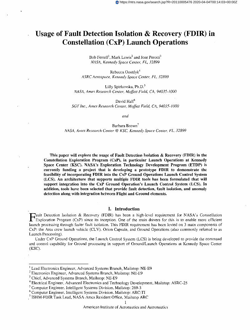
Usage of Fault Detection Isolation & Recovery (FDIR) in Constellation (CxP) Launch Operations
Bob Ferrell l, Mark Lewis2 and Jose Perotti3
NASA, Kennedy Space Center, FL, 32899
Rebecca Oostdyk4
ASRC Aerospace, Kennedy Space Center, FL, 32899
Lilly Spirkovska, Ph.D.s NASA, Ames Research Center, Moffett Field, CA, 94035-1000
David Ha1l6
SeT Inc., Ames Research Center, Moffett Field, CA, 94035-1000
and
Barbara Brown7
NASA, Ames Research Center @ KSC, Kennedy Space Center, FL, 32899
This paper will explore the usage of Fault Detection Isolation & Recovery (FDIR) in the Constellation Exploration Program (CxP), in particular Launch Operations at Kennedy Space Center (KSC). NASA's Exploration Technology Development Program (ETDP) is currently funding a project that is developing a prototype FDIR to demonstrate the feasibility of incorporating FDIR into the CxP Ground Operations Launch Control System (LCS). An architecture that supports multiple FDIR tools has been formulated that will support integration into the CxP Ground Operation's Launch Control System (LCS). In addition, tools have been selected that provide fault detection, fault isolation, and anomaly detection along with integration between Flight and Ground elements.
I. Introduction
Fault Detection Isolation & Recovery (FDIR) has been a high-level requirement for NASA's Constellation Exploration Program (CxP) since its inception. One of the main drivers for this is to enable more efficient
launch processing through faster fault isolation. This FDIR requirement has been levied on 3 main components of CxP: the Ares crew launch vehicle (CL V), Orion Capsule, and Ground Operations (also commonly referred to as Launch Processing).
Under CxP Ground Operations, the Launch Control System (LCS) is being developed to provide the command and control capability for Ground processing in support of GroundlLaunch Operations at Kennedy Space Center (KSC).
I Lead Electronics Engineer, Advanced Systems Branch, Mailstop: NE-E9 2 Electronics Engineer, Advanced Systems Branch, Mailstop: NE-E9 3 Chief, Advanced Systems Branch, Mailstop: NE-E9 4 Electrical Engineer, Advanced Electronics and Technology Development, Mailstop: ASRC-25 5 Computer Engineer, Intelligent Systems Division, Mailstop: 269-3 6 Computer Engineer, Intelligent Systems Division, Mailstop: ARC:TI
.7 ISHM-FDIR Task Lead, NASA-Ames Resident Office, Mailstop ARC 1
American Institute of Aeronautics and Astronautics
https://ntrs.nasa.gov/search.jsp?R=20110005476 2020-04-04T00:14:03+00:00Z
As part of the CXP initial concept development, a reportl entitled "Diagnostic Technology Evaluation Report for On-Board Crew Launch Vehicle" was performed by NASA Ames Research Center (ARC). This report evaluated the state of art practice in embedded fault detection and diagnosis technologies for Crew Launch Vehicle (CL V) requirements development. Based on the results of this report, both the Orion and the Ares launch vehicle selected the Testability Engineering And Maintenance System (TEAMS) toolset. TEAMS is a Commercial Off The Shelf (COTS) product by Qualtech Systems Inc. (QSI) utilized to implement FDIR.
However, the initial LCS allocation for the FDIR requirement was to have individual sub-systems (i.e. Liquid Hydrogen (LH2), Liquid Oxygen (LOX), Ground Special Power (GSP), Main Propulsion System (MPS), Avionics, Pneumatics, etc.) perform separate FDIR. This approach is similar in nature to how the current Space Shuttle Launch Processing System (LPS) handles FDIR at KSC.
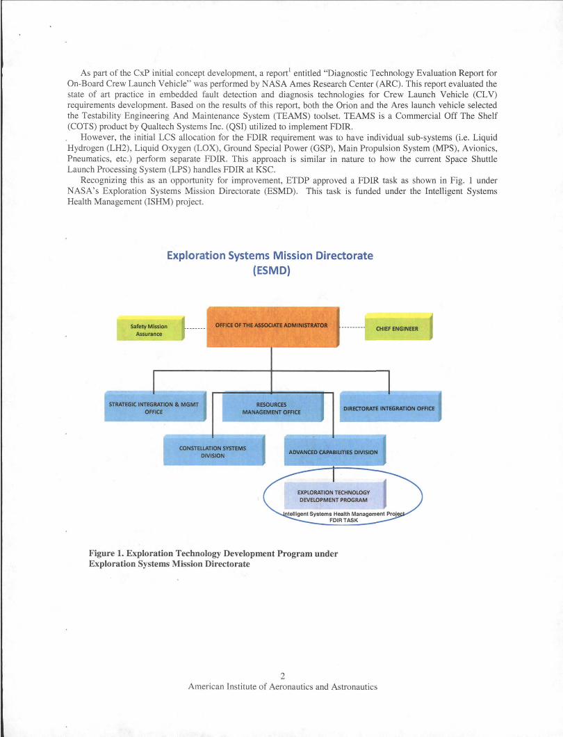
Recognizing this as an opportunity for improvement, ETDP approved a FDIR task as shown in Fig. 1 under NASA's Exploration Systems Mission Directorate (ESMD) . This task is funded under the Intelligent Systems Health Management (ISHM) project.
Safety Mission Assurance
Exploration Systems Mission Directorate (ESMD)
omaO'THEASSOCIATIADMINISTIIATOIt . CHIEF ENGINEER
STRATEGIC INTEGRATION & MGMT OFFICE
RESOURCES MANAGEMENT OFFICE
DIRI!CTORATE INTEGRATION OFFICE
CONSTELlATION SYSTEMS DIVISION
ADVANCED CAPABILITIES DMSION
Figure 1. Exploration Technology Development Program under Exploration Systems Mission Directorate
2 American Institute of Aeronautics and Astronautics
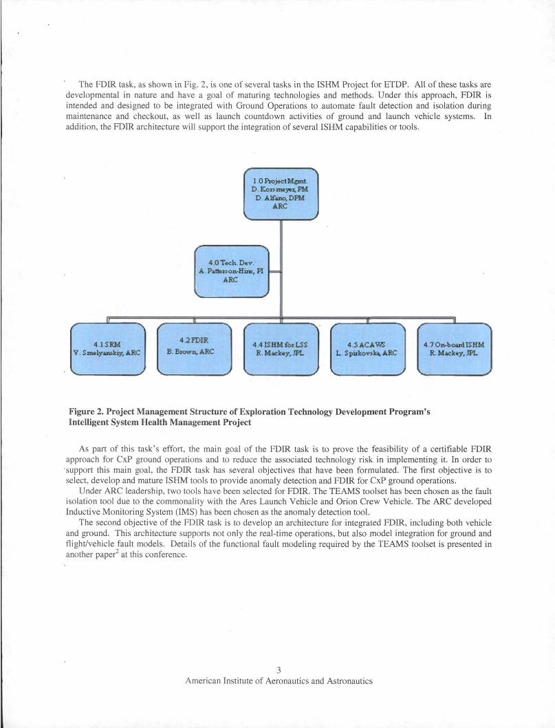
The FDIR task, as shown in Fig. 2, is one of several tasks in the ISHM Project for ETDP. All of these tasks are developmental in nature and have a goal of maturing technologies and methods. Under this approach, FDIR is intended and designed to be integrated with Ground Operations to automate fault detection and isolation during maintenance and checkout, as well as launch countdown activities of ground and launch vehicle systems. In addition, the FDIR architecture will support the integration of several ISHM capabilities or tools.
1 .0 PIojt,ctMcmt D . Kon_~~PM
D. An-,DPM AR<:
4 .0Totch. Dtv. A. P, I»l1on.Him, PI ~
ARC
4.1SRM 4.2FDIR
4 .4 ISHM (Ol'LSS 4 .5 ACAWS 4 .70n4>oudlSHM V. S_lyuuJciy,ARC B. Brown, ARC R. Mack_y, JPL L . S pirlcoY$~ ARC R. Mackey, JPL
Figure 2. Project Management Structure of Exploration Technology Development Program's Intelligent System Health Management Project
As part of this task's effort, the main goal of the FDIR task is to prove the feasibility of a certifiable FDIR approach for CXP ground operations and to reduce the associated technology risk in implementing it. In order to
'support this main goal , the FDIR task has several objectives that have been formulated . The first objective is to select, develop and mature ISHM tools to provide anomaly detection and FDIR for CXP ground operations.
Under ARC leadership, two tools have been selected for FDIR. The TEAMS toolset has been chosen as the fault isolation tool due to the commonality with the Ares Launch Vehicle and Orion Crew Vehicle. The ARC developed Inductive Monitoring System (IMS) has been chosen as the anomaly detection tool.
The second objective of the FDIR task is to develop an architecture for integrated FDIR, including both vehicle and ground. This architecture supports not only the real-time operations, but also model integration for ground and flight/vehicle fault models. Details of the functional fault modeling required by the TEAMS toolset is presented in another paper2 at this conference.
3 American Institute of Aeronautics and Astronautics
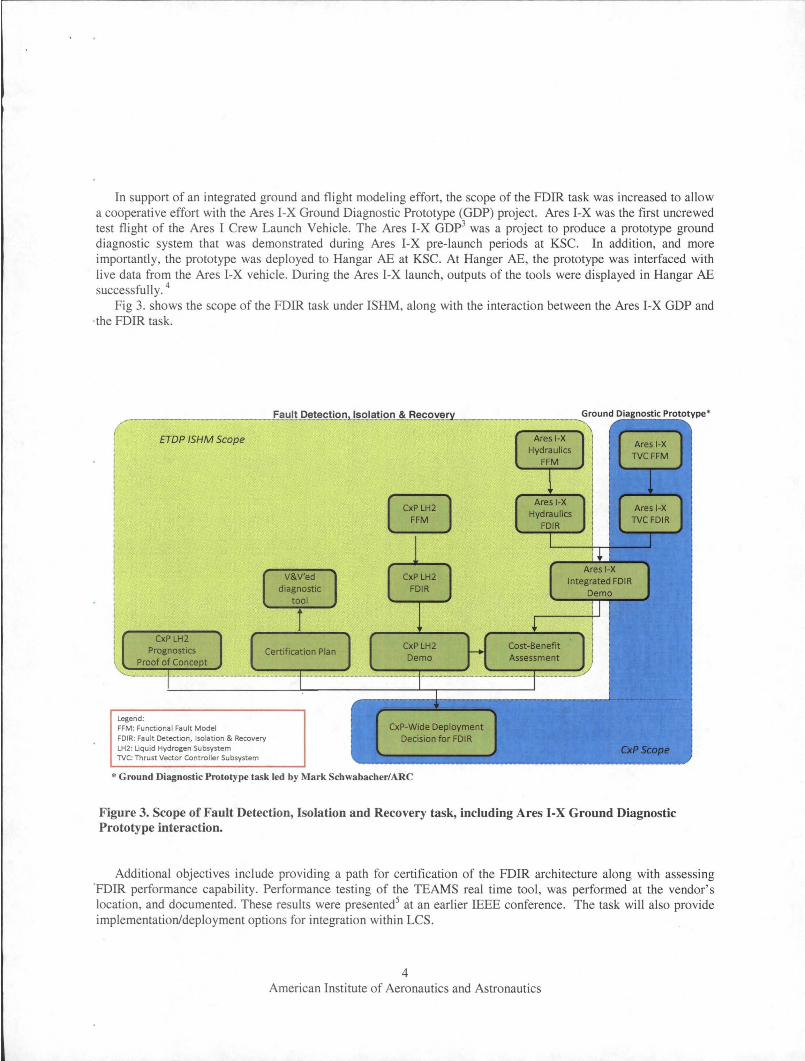
In support of an integrated ground and flight modeling effort, the scope of the FDIR task was increased to allow a cooperative effort with the Ares I-X Ground Diagnostic Prototype CGDP) project. Ares I-X was the first uncrewed test flight of the Ares I Crew Launch Vehicle. The Ares I-X GDp3 was a project to produce a prototype ground diagnostic system that was demonstrated during Ares I-X pre-launch periods at KSC. In addition, and more importantly, the prototype was deployed to Hangar AE at KSC. At Hanger AE, the prototype was interfaced with live data from the Ares I-X vehicle. During the Ares I-X launch, outputs of the tools were displayed in Hangar AE successfully. 4
Fig 3. shows the scope of the FDIR task under ISHM, along with the interaction between the Ares I-X GDP and ·the FDIR task.
ETDP ISHM Scope
Legend: FFM: Functional Fault Model FDIR: Fau lt Detection, Isolation & Recovery lH2: Uquid Hydrogen Subsystem TVC: Thrust Vector Controller Subsystem
CxP-Wide Deployment Decision for FDIR
* Ground Diagnostic Prototype task led by Mark Schwabacher/ARC
Figure 3. Scope of FauIt Detection, Isolation and Recovery task, including Ares I-X Ground Diagnostic Prototype interaction.
Additional objectives include providing a path for certification of the FDIR architecture along with assessing 'FDIR performance capability. Performance testing of the TEAMS real time tool, was performed at the vendor's location, and documented. These results were presented5 at an earlier IEEE conference. The task will also provide implementation/deployment options for integration within LCS.
4 American Institute of Aeronautics and Astronautics
Finally, the task has an out-year objective to initiate proof-of-concepts for ground subsystem prognostics applications which is beyond the scope of this paper to cover. For ease of purpose, the FDIR task will be referred to as the FDIR project in the rest of this paper.
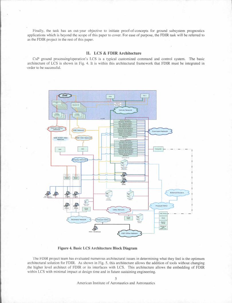
II. LCS & FDIR Architecture CXP ground processing/operation's LCS is a typical customized command and control system. The basic
architecture of LCS is shown in Fig. 4. It is within this architectural framework that FDIR must be integrated in ·order to be successful.
GSE g ~ .------L -'--~--------------------"'---~---I------------------
~ --
--_1~_
-----------------......,--------"~OJN"-' ------......,-------"Me
SMC
Figure 4. Basic LCS Architecture Block Diagram
----
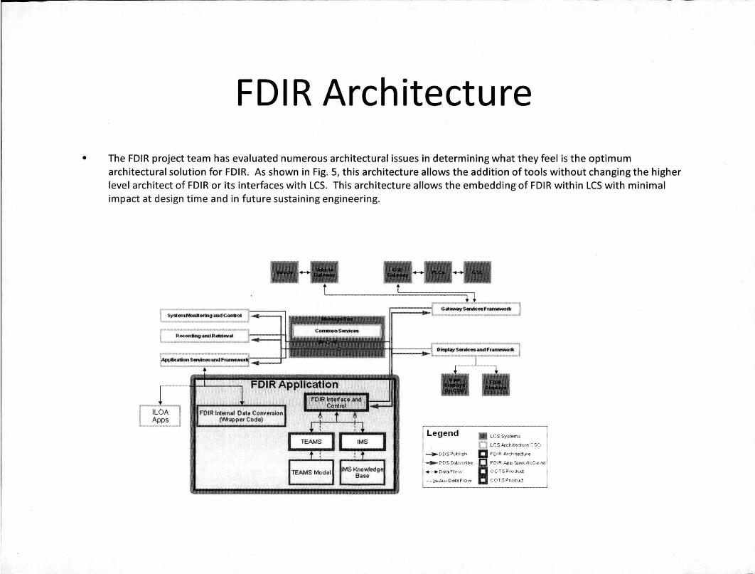
The FlJlR project team has evaluated numerous architectural issues in determining what they feel is the optimum architectural solution for FDIR. As shown in Fig. 5, this architecture allows the addition of tools without changing
.the higher level architect of FDIR or its interfaces with LCS. This architecture allows the embedding of FDIR within LCS with minimal impact at design time and in future sustaining engineering.
5 American Institute of Aeronautics and Astronautics
SyatemMonito.ing iMld Comrol
ILOA Apps
Recording >I,d Retriellill
Dlep~S."'lceean(l f.arnewol1C
Legend
_ DDSPubli.h
• LCSSystem.
LCS kchitedure CSCI
FOIR ArchitedlR'e
..... DOSSUbsctibe FD1R.tpp Spec.lieOevel
..-.. OM:Ji flow B o.O TS Produd
•• :>-Pvx D~8 F lOW co 1S Product
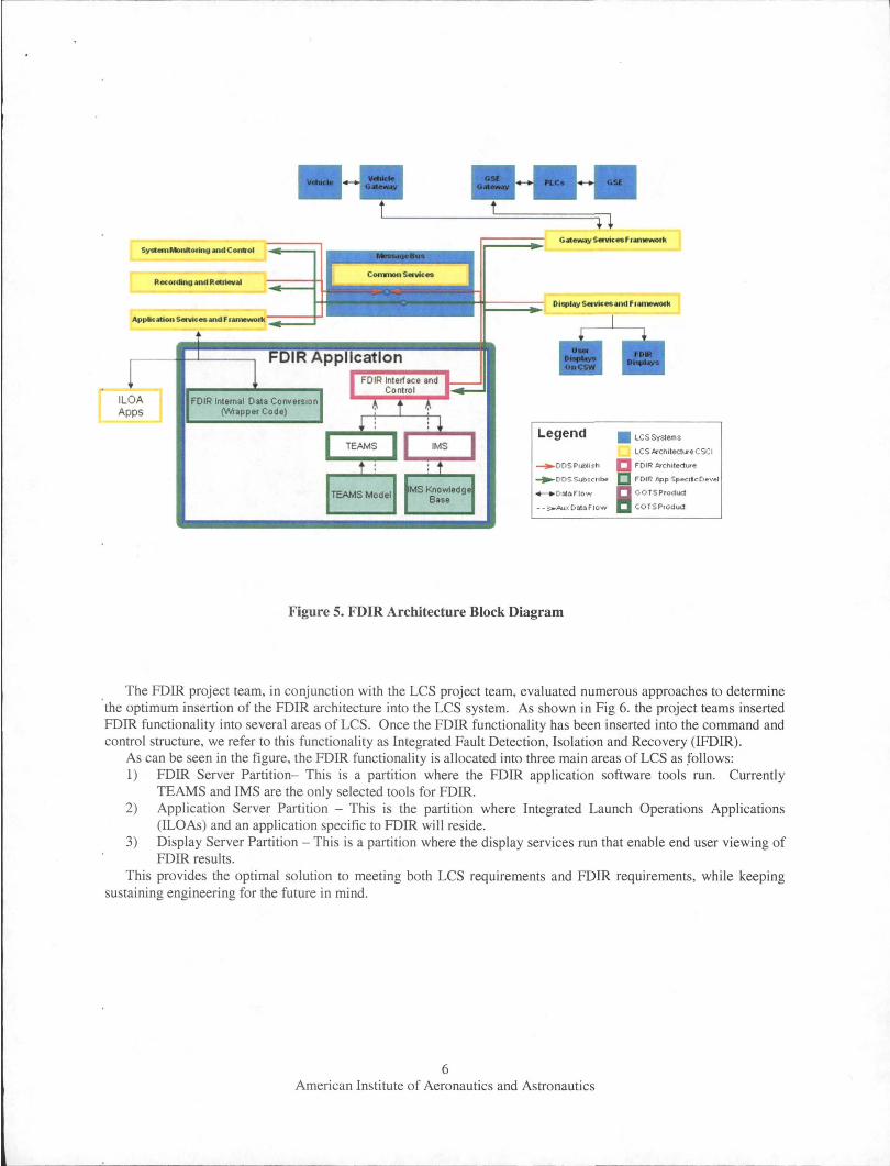
Figure 5. FDIR Architecture Block Diagram
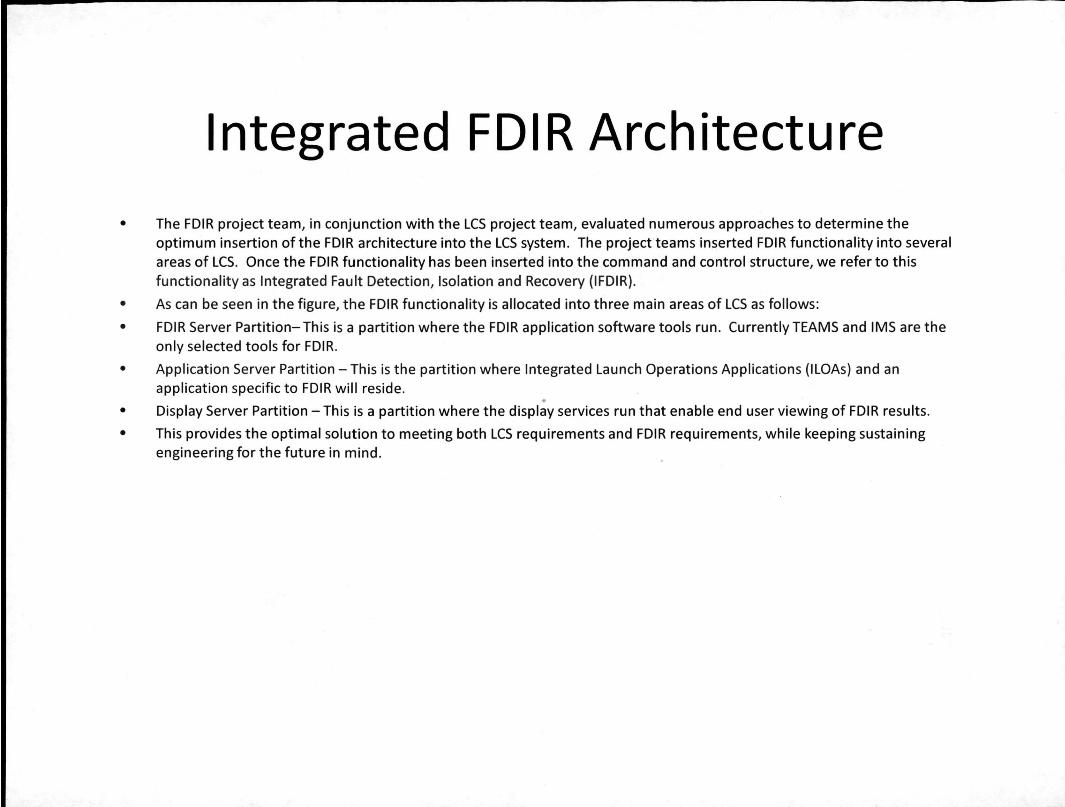
The FDIR project team, in conjunction with the LCS project team, evaluated numerous approaches to determine the optimum insertion of the FDIR architecture into the LCS system. As shown in Fig 6. the project teams inserted FDIR functionality into several areas of LCS. Once the FDIR functionality has been inserted into the command and control structure, we refer to this functionality as Integrated Fault Detection, Isolation and Recovery (IFDIR).
As can be seen in the figure, the FDIR functionality is allocated into three main areas of LCS as follows: 1) FDIR Server Partition- This is a partition where the FDIR application software tools run. Currently
TEAMS and IMS are the only selected tools for FDIR. 2) Application Server Partition - This is the partition where Integrated Launch Operations Applications
(ILOAs) and an application specific to FDIR will reside. 3) Display Server Partition - This is a partition where the display services run that enable end user viewing of
FDIR results. This provides the optimal solution to meeting both LCS requirements and FDIR requirements, while keeping
sustaining engineering for the future in mind.
6 American Institute of Aeronautics and Astronautics
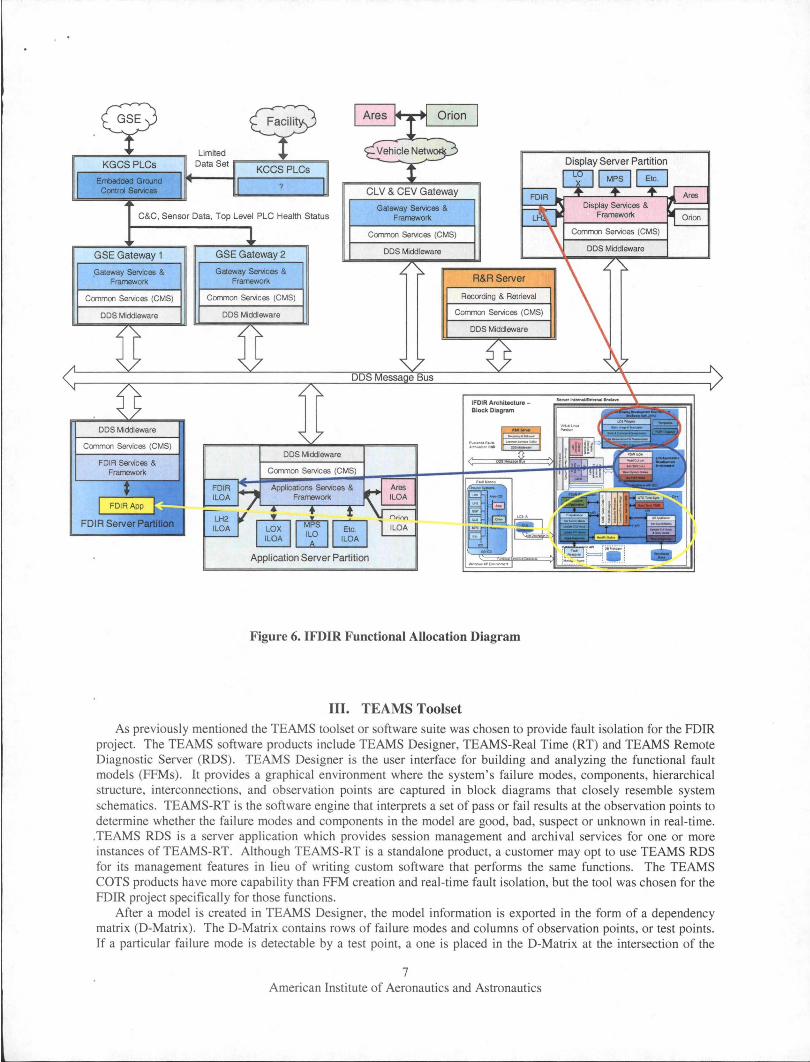
Figure 6. IFDIR Functional Allocation Diagram
III. TEAMS Toolset As previously mentioned the TEAMS toolset or software suite was chosen to provide fault isolation for the FDIR
project. The TEAMS software products include TEAMS Designer, TEAMS-Real Time (RT) and TEAMS Remote Diagnostic Server (RDS). TEAMS Designer is the user interface for building and analyzing the functional fault models (FFMs). It provides a graphical environment where the system's failure modes, components, hierarchical structure, interconnections, and observation points are captured in block diagrams that closely resemble system schematics. TEAMS-RT is the software engine that interprets a set of pass or fail results at the observation points to determine whether the failure modes and components in the model are good, bad, suspect or unknown in real-time . . TEAMS RDS is a server application which provides session management and archival services for one or more instances of TEAMS-RT. Although TEAMS-RT is a standalone product, a customer may opt to use TEAMS RDS for its management features in lieu of writing custom software that performs the same functions. The TEAMS COTS products have more capability than FFM creation and real-time fault isolation, but the tool was chosen for the FDIR project specifically for those functions .
After a model is created in TEAMS Designer, the model information is exported in the form of a dependency matrix (D-Matrix). The D-Matrix contains rows of failure modes and columns of observation points, or test points. If a particular failure mode is detectable by a test point, a one is placed in the D-Matrix at the intersection of the
7 American Institute of Aeronautics and Astronautics
failure mode and test point. A model will export one D-Matrix for each system mode or configuration that is identified by the modeler. The system modes are defined by unique combinations of switches in the model that enable or disrupt the failure effect propagation paths (FEPPs).
Once the D-Matrices have been defined, the TEAMS-RT engine uses them to isolate faults to a failure mode or modes based on the pass or fail state of the test points. The TEAMS-RT engine outputs lists of failure modes that ·are "bad", "suspect" and "unknown", and all other failure modes are assumed "good." A failure mode which is "good," or not failed, is one which is mapped to any test point with a pass result. A "bad" failure mode is one which has a FEPP to a test point with a failed result, where the test point is not mapped to any other failure modes besides failure modes that have already been determined to be "good." A "suspect" failure mode is one which has a FEPP to a test point with a failed result and the failure mode is not the only failure mode mapped to that test point. "Suspect" failure modes are by definition an ambiguity group for a single test point. Finally, "unknown" failure modes are those failure modes whose FEPPs map only to test points for which there are no pass or fail results.
Since the model includes hierarchy information that relates a failure mode to a component or other higher level (such as a line replaceable unit or subsystem), the same D-Matrix can be used to diagnose the system at different
·levels of resolution depending on the needs of the application
IV. IMS IMS uses a data-driven machine learning technique that automatically extracts system parameter relationships
and interactions from archived nominal system data producing a monitoring capability quickly for almost any system for which archived nominal data is available. IMS does not require knowledge engineers or modelers to capture precise details of system operation. It only requires archived nominal data. Lacking that, IMS can learn the ·relationship based on the parameter values from a high-fidelity simulator, with the accuracy of the simulator determining the accuracy of learned monitoring capability. When neither operational nor simulated data is available for a system, IMS can be trained on a very similar system. However, as with simulated data, the accuracy of the .learned monitoring capability will depend on the similarity of the systems.
IMS has two phases: training and monitoring. Training is done off-line and monitoring can be done on-line (realtime monitoring) or off-line (post-flight analysis). The goal during the training phase is to learn how the system normally behaves. The input to the learning algorithm is a data set representing nominal system operation. The training flow consists of the following: From the full set of data sensors available, the user selects the subset of parameters that adequately encode the behavior of the system. These parameters, normalized and weighted to assign . desired significance, are formed into a data vector. The user can then clean/validate the training set by eliminating outlier vectors. IMS is trained on most of the cleaned data set, with the exception of a portion left out to validate learning generalization. When satisfied with the performance (generalization and speed on the target hardware), IMS is trained on the full, cleaned data set.
The goal of the monitoring step is to determine if the system is behaving differently than during operations when training data was collected. The monitoring step extracts the relevant parameters from the incoming real-time system data, normalizes and weights them, as was done during training, and then compares the incoming vector to the clusters generated during training. It outputs similarity scores, the distance between the vector and the nearest cluster for the vector as a whole (a composite score) and a distance from the nearest cluster for each parameter ·separately. These distances represent the deviation of the current operation from nominal operations as defined by the training set - a measure of how "out of family" the behavior is. These scores can then be sent through an Alert Logic Filter to filter out data spikes and issue alerts only when a specified number of sequential incoming vectors are anomalous. Alternatively, the scores can be plotted allowing users to assess the severity of any system anomalies and watch for worsening trends over time.
V. Conclusion FDIR is intended and designed to be integrated with Ground Operations to automate fault detection & isolation
and anomaly detection during maintenance and checkout as well as launch countdown activities of ground and launch vehicle systems. The FDIR architecture described in this paper supports the integration of tools to support these activities and future tools.
8 American Institute of Aeronautics and Astronautics

The two initial tools chosen for incorporation into the FDIR project are the TEAMS toolset from Qualtech .Systems Inc. and IMS from NASA ARC. By integrating FDIR functionality into LCS as described in this paper the following benefits are expected to be achieved:
1) Increased Crew Safety - Improve timely detection of mission-critical and life-critical failures and the identification/initiation/execution of recovery procedures.
2) Increased System Availability - Improve system availability to perform intended mission and meet CxP operability requirements.
3) Reduced LifecycIe Costs - Provide more efficient and effective isolation of failures. It is hoped that the knowledge gained during the execution of this project will be applied not only to current and
future launch systems at KSC, but will also find use for future extra-planetary missions
Acknowledgments We would like to thank NASA's Exploration Technology Development Program for their past and future
funding of the Fault Detection, Isolation and Recovery project to develop and mature fault isolation technologies for future space missions.
References IHayden, S., Oza, N., Mah, R., Mackey, R., Narasimhan, S., Karsai, G., Poll, S., Deb, S., and Shirley, M., "Diagnostic
'Technology Evaluation Report for On-Board Crew Launch Vehicle," NASA/TM-2006-214552, September 2006. 2Ferrell, B., Brown, B., Lewis, M., Oostdyk, R., and Perotti, J., "Functional Fault Modeling Conventions and Practices
for Real-Time Fault Isolation," Proceedings of the AlAA SpaceOps 2010 Conference, AIAA, Huntsville, AL, 2010. 3Schwabacher, M. and Waterman, R., "Pre-Launch Diagnostics for Launch Vehicles," Proceedings of the IEEE Aerospace
Conference, IEEE and AIAA, Big Sky, MT, 2008. 4Schwabacher, M., Martin, R., Waterman, R., Oostdyk, R., Ossenfort, J., and Matthews, B., "Ares I-X Ground Diagnostic
Prototype," Proceedings of the A1AA infoTech@Aerospace Conference, AIAA,Atlanta, GA, 2010. Submitted for publication. 5Ferrell, B. and Oostdyk, R., "Modeling and Performance Considerations for Automated Fault Isolation in Complex
Systems," Aerospace Conference Proceedings, IEEE, Washington, DC, 2010, 978-1-4244-3888 6Spirkovska, L., Iverson, D.L., Hall, D.R., Taylor, W.M., Patterson-Hine, A., Brown, B.L., Ferrell, B.A., and Waterman,
. R.D., "Anomaly Detection for Next-Generation Space Launch Ground Operations," Proceedings of the A1AA SpaceOps 2010 Conference, AIAA, Huntsville, AL, 2010.
9 American Institute of Aeronautics and Astronautics
Usage of Fault Detection Isolation & . Recovery (FDIR) in Constellation (CxP)
Launch Operations
Presented by Bob Ferrell NASA, Kennedy Space Center, FL, 32899
AIAA SpaceOps 2010 Conference - Huntsville, AL
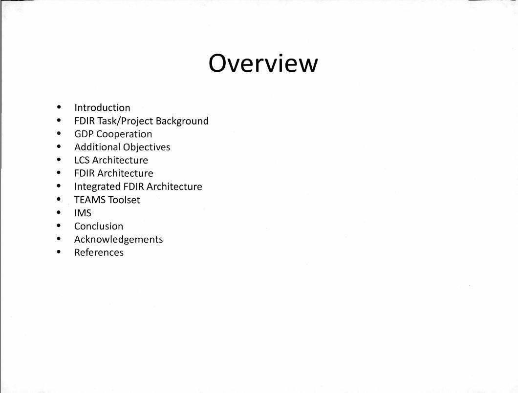
Overview
• Introduction
• FOIR Task/Project Background
• GOP Cooperation
• Additional Objectives
• LCS Architecture
• FOIR Architecture
• Integrated FOIR Architecture
• TEAMS Toolset
• IMS
• Conclusion
• Acknowledgements
• References
Introduction
This presentation will explore the usage of Fault Detection Isolation & Recovery (FDIR) in the Constellation Exploration Program (CxP), in particular Launch Operations at Kennedy Space Center (KSC). NASA's Exploration Technology Development Program (ETDP) is currently funding a project that is developing a prototype FDIR to demonstrate the feasibility of incorporating FDIR into the CxP Ground Operations Launch Control System (LCS). An architecture that supports multiple FDIR tools has been formulated that will support integration into the CxP Ground Operation's Launch Control System (LCS). In addition, tools have been selected that provide fault detection, fault isolation, and anomaly detection along with integration between Flight and Ground elements.
Introduction
• Fault Detection Isolation & Recovery (FDIR) has been a high-level requirement for NASA's Constellation Exploration Program (CxP) since its inception. One of the main drivers for this is to enable more efficient launch processing through faster fault isolation. This FDIR requirement has been levied on 3 main components of CxP: the Ares crew launch vehicle (CLV), Orion Capsule, and Ground Operations (also commonly referred to as Launch Processing).
• Under CxP Ground Operations, the Launch Control System (LCS) is being developed to provide the command and control capability for Ground processing in support of Ground/Launch Operations at Kennedy Space Center (KSC).
• As part of the CxP initial concept development, a reportl entitled "Diagnostic Technology Evaluation Report for On-Board Crew Launch Vehicle" was performed by NASA Ames Research Center (ARC). This report evaluated the state of art practice in embedded fault detection and diagnosis technologies for Crew Launch Vehicle (CLV) requirements development. Based on the results of this report, both the Orion and the Ares launch vehicle selected the Testability Engineering And Maintenance System (TEAMS) toolset. TEAMS is a Commercial Off The Shelf (COTS) product by Qualtech Systems Inc. (QSI) utilized to implement FDIR.
• However, the initial LCS allocation for the FDIR requirement was to have individual sub-systems (Le. Liquid Hydrogen (LH2), Liquid Oxygen (LOX), Ground Special Power (GSP), Main Propulsion System (MPS), Avionics, Pneumatics, etc.) perform separate FDIR. This approach is similar in nature to how the current Space Shuttle Launch Processing System (LPS) handles FDIR at KSC.
• Recognizing this as an opportunity for improvement, ETDP approved a FDIR task under NASA's Exploration Systems Mission Directorate (ESMD). This task is funded under the Intelligent Systems Health Management (ISHM) project.
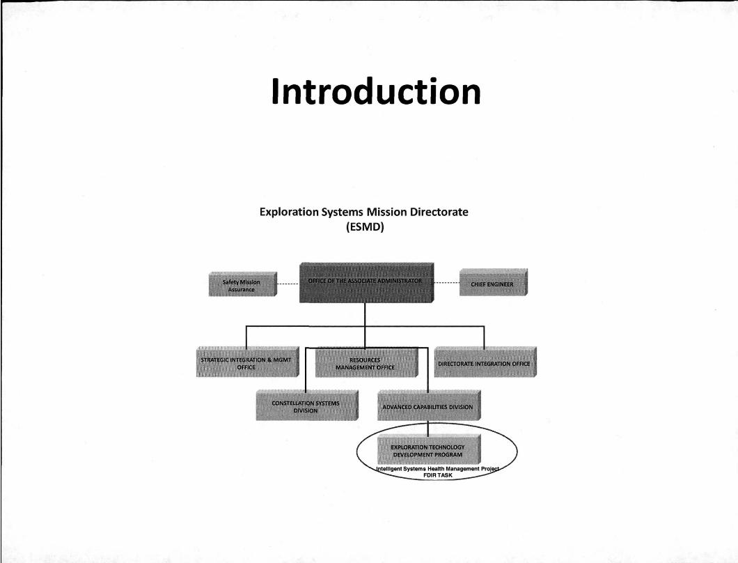
Introduction
Exploration Systems Mission Directorate (ESMD)
Introduction
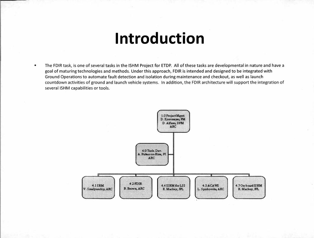
• The FDIR task, is one of several tasks in the ISHM Project for ETDP. All ofthese tasks are developmental in nature and have a goal of maturing technologies and methods. Under this approach, FDIR is intended and designed to be integrated with Ground Operations to automate fault detection and isolation during maintenance and checkout, as well as launch countdown activities of ground and launch vehicle systems. In addition, the FDIR architecture will support the integration of severallSHM capabilities or tools.
1.0 Ploject Mcmt. D. Kbtt_Yt~ PM D.AlADo.·[)PM
l ARC
.J
4.0 Tteh, o.v. ~,~0JI0.8~. PI -ARC
: 4.2J'DIR I 4.1SR.M 4.4 lSKMtWl.SS 4.S A<;A'1iJJS i 4.7 Ol\~oo4tsBM
V .. S_ly~ARC 8 .8lQWlf,..uc ! R. MIiI:hy.lPL L.SpWconD. ARC R.Mdcq. JPL
I
FDIR Task/Project
• As part of this task's effort, the main goal of the FDIR task is to prove the feasibility of a certifiable FDIR approach for CxP ground operations and to reduce the associated technology risk in implementing it. In order to support this main goal, the FDIR task has several objectives that have been formulated. The first objective is to select, develop and mature ISHM tools to provide anomaly detection and FDIR for CxP ground operations.
• Under ARC leadership, two tools have been selected for FDIR. The TEAMS toolset has been chosen as the fault isolation tool due to the commonality with the Ares Launch Vehicle and Orion Crew Vehicle. The ARC developed Inductive Monitoring System (IMS) has been chosen as the anomaly detection tool.
• The second objective of the FDIR task is to develop an architecture for integrated FDIR, including both vehicle and ground. This architecture supports not only the real-time operations, but also model integration for ground and flight/vehicle fault models. Details of the functional fault modeling required by the TEAMS toolset is presented in another paper2 at this conference.
GOP Cooperation
• In support of an integrated ground and flight modeling effort, the scope ofthe FDIR task was increased to allow a cooperative effort with the Ares I-X Ground Diagnostic Prototype (GDP) project. Ares I-X was the first uncrewed test flight of the Ares I Crew Launch Vehicle. The Ares I-X GDp3 was a project to produce a prototype ground diagnostic system that was demonstrated during Ares I-X pre-launch periods at KSC. In addition, and more importantly, the prototype was deployed to Hangar AE at KSC. At Hanger AE, the prototype was interfaced with live data from the Ares I-X vehicle. During the Ares I-X launch, outputs of the tools were displayed in Hangar AE successfully.
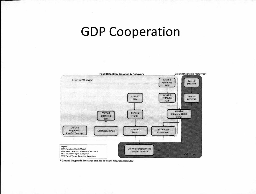
GDP Cooperation
ETOP ISHM Scope
Legend: FFM : Functional Fault Model
FOIR: Fault Detection, Isolation & Recovery lH2 : Uquid Hydrogen Subsystem TVC: Thrust Vector Controller Subsystem
CxP-Wide Deployment Decision for FDIR
* Ground Diagnostic Prototype task led by Mark Schwabacber/ARC
Additional Objectives
• Additional objectives include providing a path for certification of the FDIR architecture along with assessing FDIR performance capability. Performance testing of the TEAMS real time toot was performed at the vendor's location, and documented. These results were presentedS at an earlier IEEE conference. The task will also provide implementation/deployment options for integration with in LCS.
• Finally, the task has an out-year objective to initiate proof-of-concepts for ground subsystem prognostics applications which is beyond the scope of this paper to cover. For ease of purpose, the FDIR task will be referred to as the FDIR project in the rest of this paper .
• • lCS & FDIR Architecture
• CxP ground processing/operation's LCS is a typical customized command and control system.
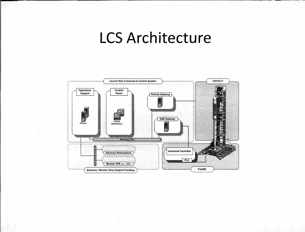
LCS Architecture
---- -------- ..... . . I
' I MvtsOf)'Worhta&n~ I' ... - -_ ..... "" -- -_ .... _-- .... ,
! ' I MOl1itorVl'lS l~.o _~RI I' : J .~ ............... ( A4vI$(Ify I t,l11f1.1Wr On!~ $I,IPPQrt FI!elflilll$ )_~' __ "''''' __ 'd
FDIR Architecture
• The FDIR project team has evaluated numerous architectural issues in determining what they feel is the optimum architectural solution for FDIR. As shown in Fig. 5, this architecture allows the addition of tools without changing the higher level architect of FDIR or its interfaces with LCS. This architecture allows the embedding of FDIR within LCS with minimal impact at design time and in future sustaining engineering.
Legend LC$:5ystem~
[J Lt:S . .c.,.chlt,;:·:tuf" r:·:;r:r
...... r' nsr'lll:>hsh 1:1 F"D1R .c.r~~'EtecturE' ....... ('IDS £ubtctibe [] FOIR App ";peclllc.Gew;:!
+-+ D~t.')ft.,· ..... · B (~C'TSProdIJd •. ~;:.~ .. u . bM3FIOw cc,rS F'rudu ... 1
Integrated FDIR Architecture
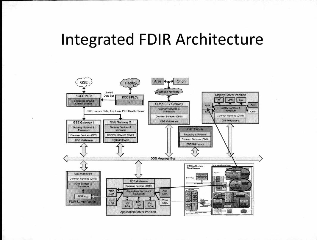
• The FDIR project team, in conjunction with the LCS project team, evaluated numerous approaches to determine the optimum insertion ofthe FDIR architecture into the LCS system. The project teams inserted FDIR functionality into several areas of LCS. Once the FDIR functionality has been inserted into the command and control structure, we refer to this functionality as Integrated Fault Detection, Isolation and Recovery (IFDIR).
• As can be seen in the figure, the FDIR functionality is allocated into three main areas of LCS as follows:
• FDIR Server Partition- This is a partition where the FDIR application software tools run. Currently TEAMS and IMS are the only selected tools for FDIR.
• Application Server Partition - This is the partition where Integrated Launch Operations Applications (ILOAs) and an application specific to FDIR will reside. .
• Display Server Partition - This is a partition where the display services run that enable end user viewing of FDIR results.
• This provides the optimal solution to meeting both LCS requirements and FDIR requirements, while keeping sustaining engineering for the future in mind.
Integrated FDIR Architecture
IFDIR Archltectu,..Block Diagram
TEAMS Toolset
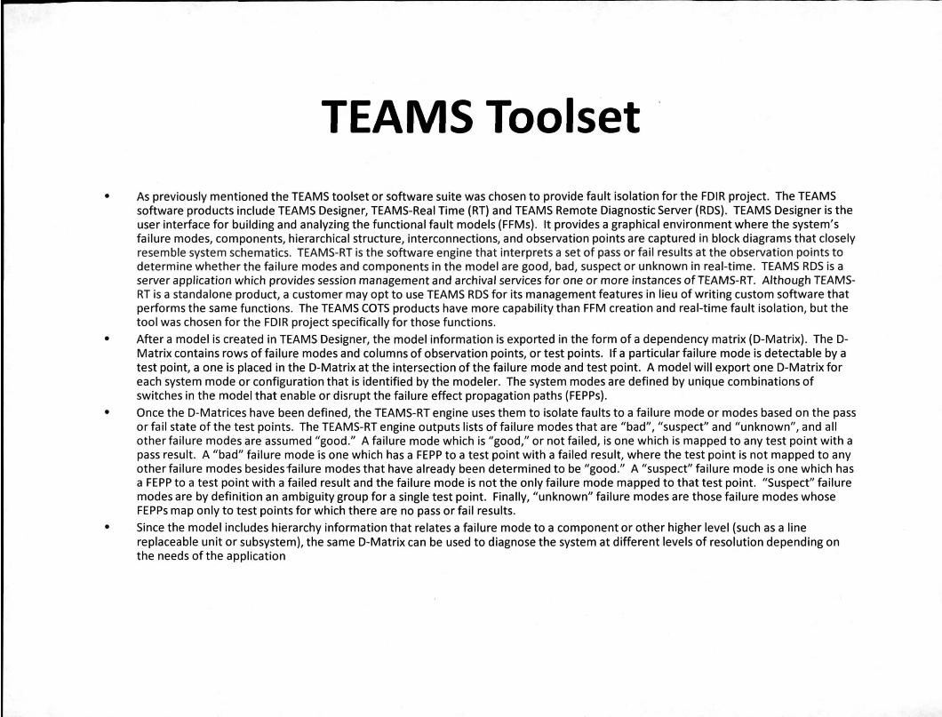
• As previously mentioned the TEAMS toolset or software suite was chosen to provide fault isolation for the FDIR project. The TEAMS software products include TEAMS Designer, TEAMS-Real Time (RT) and TEAMS Remote Diagnostic Server (RDS). TEAMS Designer is the user interface for building and analyzing the functional fault models (FFMs). It provides a graphical environment where the system's failure modes, components, hierarchical structure, interconnections, and observation points are captured in block diagrams that closely resemble system schematics. TEAMS-RT is the software engine that interprets a set of pass or fail results at the observation points to determine whether the failure modes and components in the model are good, bad, suspect or unknown in real-time. TEAMS RDS is a server application which provides session management and archival services for one or more instances of TEAMS-RT. Although TEAMSRT is a standalone product, a customer may opt to use TEAMS RDS for its management features in lieu of writing custom software that performs the same functions. The TEAMS COTS products have more capability than FFM creation and real-time fault isolation, but the tool was chosen for the FDIR project specifically for those functions.
• After a model is created in TEAMS Designer, the model information is exported in the form of a dependency matrix (D-Matrix) . The DMatrix contains rows of failure modes and columns of observation points, or test points. If a particular failure mode is detectable by a test point, a one is placed in the D-Matrix at the intersection of the failure mode and test point. A model will export one D-Matrix for each system mode or configuration that is identified by the modeler. The system modes are defined by unique combinations of switches in the model that enable or disrupt the failure effect propagation paths (FEPPs) .
• Once the D-Matrices have been defined, the TEAMS-RT engine uses them to isolate faults to a failure mode or modes based on the pass or fail state of the test points. The TEAMS-RT engine outputs lists of failure modes that are "bad", "suspect" and "unknown", and all other failure modes are assumed "good." A failure mode which is "good," or not failed, is one which is mapped to any test point with a pass result. A "bad" failure mode IS one which has a FEPP to a test point with a failed result, where the test point is not mapped to any other failure modes besides failure modes that have already been determined to be "good." A "suspect" failure mode is one which has a FEPP to a test point with a failed result and the failure mode is not the only failure mode mapped to that test point. "Suspect" failure modes are by definition an ambiguity group for a single test point. Finally, "unknown" failure modes are those failure modes whose FEPPs map only to test points for which there are no pass or fail results.
• Since the model includes hierarchy information that relates a failure mode to a component or other higher level (such as a line replaceable unit or subsystem), the same D-Matrix can be used to diagnose the system at different levels of resolution depending on the needs of the application
IMS
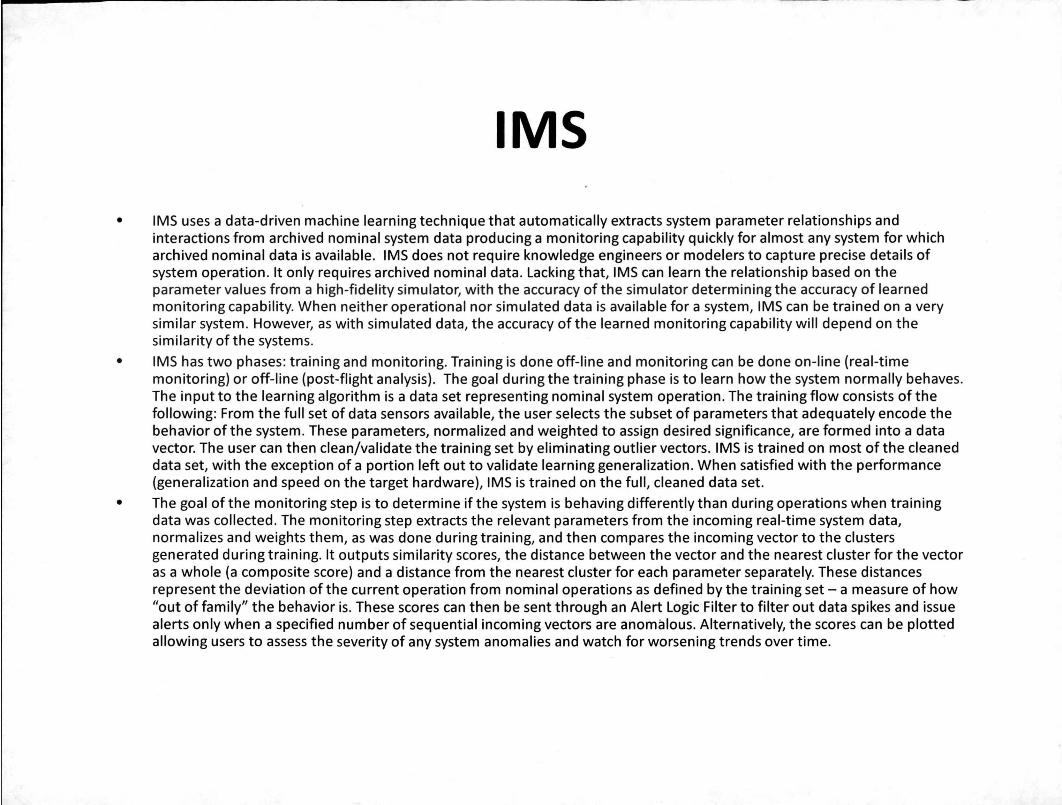
• IMS uses a data-driven machine learning technique that automatically extracts system parameter relationships and interactions from archived nominal system data producing a monitoring capability quickly for almost any system for which archived nominal data is available. IMS does not require knowledge engineers or modelers to capture precise details of system operation. It only requires archived nominal data. Lacking that, IMS can learn the relationship based on the parameter values from a high-fidelity simulator, with the accuracy of the simulator determining the accuracy of learned monitoring capability. When neither operational nor simulated data is available for a system, IMS can be trained on a very similar system. However, as with simulated data, the accuracy of the learned monitoring capability will depend on the similarity of the systems.
• IMS has two phases: training and monitoring. Training is done off-line and monitoring can be done on-line (real-time monitoring) or off-line (post-flight analysis). The goal during the training phase is to learn how the system normally behaves. The input to the learning algorithm is a data set representing nominal system operation. The training flow consists of the following: From the full set of data sensors available, the user selects the subset of parameters that adequately encode the behavior of the system. These parameters, normalized and weighted to assign desired significance, are formed into a data vector. The user can then clean/validate the training set by eliminating outlier vectors. IMS is trained on most of the cleaned data set, with the exception of a portion left out to validate learning generalization. When satisfied with the performance (generalization and speed on the target hardware), IMS is trained on the full, cleaned data set.
• The goal of the monitoring step is to determine if the system is behaving differently than during operations when training data was collected . The monitoring step extracts the relevant parameters from the incoming real-time system data, normalizes and weights them, as was done during training, and then compares the incoming vector to the clusters generated during training. It outputs similarity scores, the distance between the vector and the nearest cluster for the vector as a whole (a composite score) and a distance from the nearest cluster for each parameter separately. These distances represent the deviation of the current operation from nominal operations as defined by the training set - a measure of how "out of family" the behavior is. These scores can then be sent through an Alert Logic Filter to filter out data spikes and issue alerts only when a specified number of sequential incoming vectors are anomalous. Alternatively, the scores can be plotted allowing users to assess the severity of any system anomalies and watch for worsening trends over time.
Conclusion
• FDIR is intended and designed to be integrated with Ground Operations to automate fault detection & isolation and anomaly detection during maintenance and checkout as well as launch countdown activities of ground and launch vehicle systems. The FDIR architecture described in this paper supports the integration of tools to support these activities and future tools.
• The two initial tools chosen for incorporation into the FDIR project are the TEAMS toolset from Qualtech Systems Inc. and IMS from NASA ARC. By integrating FDIR functionality into LCS as described in this paper the following benefits are expected to be achieved:
• Increased Crew Safety - Improve timely detection of mission-critical and life-critical failures and the identification/initiation/execution of recovery procedures.
• Increased System Availability - Improve system availability to perform intended mission and meet CxP operability requirements.
• Reduced Lifecycle Costs - Provide more efficient and effective isolation of failures.
• It is hoped that the knowledge gained during the execution of this project will be applied not only to current and future launch systems at KSC, but will also find use for future extra-planetary missions
Acknowledgments
Special Thanks
NASA ESMD, ETDP & ISHM
FDIR Team Members
References
• Hayden,S., Oza, N., Mah, R., Mackey, R., Narasimhan,S., Karsai, G., Poll,S., Deb,S., and Shirley, M., "Diagnostic Technology Evaluation Report for On-Board Crew Launch Vehicle/' NASA/TM-2006-214552, September 2006.
• Ferrell, B., Brown, B., Lewis, M., Oostdyk, R., and Perotti, J., "Functional Fault Modeling Conventions and Practices for RealTime Fault Isolation/ ' Proceedings of the AIAA SpaceOps 2010 Conference, AIAA, Huntsville, AL, 2010.
• Schwa bacher, M. and Waterman, R., "Pre-Launch Diagnostics for Launch Vehicles/' Proceedings of the IEEE Aerospace Conference, IEEE and AIAA, Big Sky, MT, 2008.
• Schwabacher, M., Martin, R., Waterman, R., Oostdyk, R., Ossenfort, J., and Matthews, B., "Ares I-X Ground Diagnostic Prototype/' Proceedings of the AIAA InfoTech@Aerospace Conference, AIAA, Atlanta, GA, 2010. Submitted for publication.
• Ferrell, B. and Oostdyk, R., "Modeling and Performance Considerations for Automated Fault Isolation in Complex Systems/' Aerospace Conference Proceedings, IEEE, Washington, DC, 2010, 978-1-4244-3888
• Spirkovska, L., Iverson, D.L., Hall, D.R., Taylor, W.M., Patterson-Hine, A., Brown, B.L., Ferrell, B.A., and Waterman, R.D., "Anomaly Detection for Next-Generation Space Launch Ground Operations/' Proceedings of the AIAA SpaceOps 2010 Conference, AIAA, Huntsville, AL, 2010.