Embed Size (px)
Citation preview
Use of Blind Equalization For Teletext Broadcast Systems
JEYHAN KARAOGUZ, STUDENT MEMBER, IEEE, AND, SASAN H. ARDALAN, MEMBER, IEEE
Abstruct - Severe inter-symbol-interference (ISI) due to multipath fading broadcast channels requires the equalmation of digital teletext signals for reliable operation. Until now, the equalisation of the teletext signals has been achieved by conventional adaptive equalisation. However, these equal- isers need a training signal which is sent during the PO- tentiaI data transmission time. Also, conventional adaptive equalisers are very poor in tracking changing channel char- acteristics which are often encountered in feding multipath environments. This paper suggests the use of blind adap- tive equalisation, which removes the mentioned drawbacks of the conventional adaptive equalisation. The paper also deals with the compatibility of the proposed blind equalmer with the existing teletext system standards and cost-effectiveness issues. Computer simulations demonstrate substantial im- provements in the bit-error-rates for the received teletext data in a multipath transmission medium
I. INTRODUCTION
Teletext is a new television service which has gen- erated a great deal of interest in the last few years. Most of the system parameters such as data rates, pulse shapes and modulation schemes have been greatly standardized over the past years. However, there is still ongoing research and development in this area. Teletext signals are digital signals; therefore, in the presence of excess noise and, more importantly, inter-symbol-interference (ISI) due to multipath fad- ing channels, the received signal is often detected with many errors. To achieve low bit-error-rates (BER) and a reliable system a channel equalizer is needed. The design of equalizers has been one of the impor- tant research areas in teletext systems. This paper deals with the equalization of degraded teletext sig- nals. However, unlike previous works [l, 2,3] we sug- gest the blind adaptive equalization of teletext signals rather than conventional adaptive equalization. Com- mon to all of the previous adaptive equalization meth- ods is the need for an initial training period in which a particular data sequence, known and available in proper synchronization at the receiver, is transmitted. The training duration varies depending on the conver-
a
I
! 1
.4
gence rate of the algorithm being used for adaptive equalization. Practically,' LMS type adaptive equaliz- ers have been used for their cost-effectiveness and easy implementation. However, the training interval for such equalizers takes a significant amount of transmis- sion time at the expense of potential data transmis- sion time for the teletext systems. This inefficiency leads to long waiting times at the receiver. There- fore, fast convergence rates and minimum delay to- gether with reliable bit-error-rates are the paramount goals in designing teletext systems. Another source of long waiting times between consecutive teletext pages is due to the fact that teletext data transmis- sion can only take place during some of the unused vertical blanking interval (VBI) lines. However, the VBI is also used to send other synchroqization and mostly equalization pulses which are used in conven- tional adaptive equalization. These bverhead pulses, which are transmitted with the digitally coded data, can take nearly half of the vertical blanking inter- val [4]. Also, the teletext transmitter has to wait 262.5 lines for every VBI to send two lines of tele- text data. 'Remedies to these drawbacks are twofold: '(1) the training signals should be eliminated if possi- ble; and (2) the teletext transmission should not be restricted only to the VBI. A solution to the latter problem was suggested in [5] .
The use of blind equalization removes the system inefficiencies mentioned above. The blind adaptive equalizer described in Section IV does not require the use of any training signal. Also, the proposed blind equalization algorithm requires that the tele- text signal be 2-Phase PSK or QPSK modulated or, more generally be phase or FM modulated. The blind equalizer uses some invariant properties of the phase modulation technique as described in more detail in Section IV. This type of equalizer is also called a prop- erty restoral blind equalizer [6]. This is because it tries to restore the received signals based on their known invariant properties such as constant modulus or magnitude. Section II(B) discusses the use and advantages of 2-Phase PSK and QPSK modulation schemes in teletext data transmission and also their
The authors are with the Center for Communications and Sig- nal Processing, Department of Electrical and Computer Engineering, North Carolina State University, Raleigh, NC, 27695-7911.
This work W u supported by the Cents for Communications and compatibility with the casting TV systems. Signal Processing. 0018-9316/91~600-001.~ 0 1991 IEEE
IEm TRANSACTTONS ON BROADCASTING, VOL. 37, NO. 2, JUNE 1991 45
Another requirement for radio or TV broadcast channel equalizers is that they be able to track the time-varying fading characteristics of typical chan- nels. Frequently changing multipath fading channel characteristics render conventional adaptive filters in- effective since the adaptation is stopped after the train- ing period [7]. This requires waiting for retransmis- sion of the training sequence which, in turn, causes longer delays at the receiver. Therefore, the use of blind equalization for such broadcast channels is very appropriate since it tracks the channel changes con- tinuously as it restores the invariant properties of the received degraded signal without any interruption.
Any new system modification to current television systems should be easy and cheap to implement (cost- effective) and also, very importantly, should be com- patible with the already existing standards to be ac- ceptable in the mass market TV industry. There- fore, minimal change in the current television sys- tem should be a goal when a new system is proposed. The use of blind equalization is not only cost-effective and compatible with standard TV systems but it also eliminates some of the extra circuitry in existing TV sets for generating the equalizer reference or train- ing signal, the so-called ghost cancelling reference signal. In Section II(B) and I11 more discussion is presented about the cost-effectiveness and compati- bility issues of blind equalizers with existing teletext broadcast systems.
Section II(C) explains how the received teletext data signal is pre-processed before the blind equalizer. Section I11 describes where the blind equalizer and its supplementary blocks would be located in the existing TV set. Section IV provides some background about blind equalization and presents the equalization algo- rithm with some remarks about its convergence be- havior. Finally, Section V provides computer simula- tion results which indicate substantial improvements in the received teletext signal.
11. BACKGROUND A . Reception of Teletext Under Multipath Conditions
The propagation of TV signals over different paths of unequal lengths from the transmitting station to the receiver is referred to as multipath propagation. The multipath problem results in ghosts superimposed on the main TV picture and causes severe IS1 for the teletext messages. Since digital teletext data is transmitted on standard analog television systems, the teletext data reception also suffers from the same degradations, resulting in poor bit error rates. The
analog TV system is not well suited for data trans- mission. Therefore, special attention must be given to reducing the BER of the detected teletext signal. This paper examines the blind equalization of tele- text data that have been subjected to multipath dis- tortion. The primary goal of the blind equalization will be to reduce the effects of channel distortions due to multipath channels so that the receiver’s de- cisions become more reliable. The IS1 due to multi- path is much more important and effective than noise for data transmission. Therefore, the performance of the blind equalizer will be evaluated by signal-to- interference-and-noise (SINR) versus BER curves in Section V.
A multipath channel can be characterized by an impulse response given as
where a k and Q are the effective path gain and path delay for path k, respectively. For a practical channel,
is a complex number with magnitude less than one and Tk, can take any arbitrary real and positive value.
B. Modulation Format
In current TV systems, the teletext input mes- sage is in the form of narrow nonreturn-to-zero (NRZ) pulses which are then shaped by a baseband teletext transmit filter. The shaped pulses constituting the message signal are amplitude modulated and filtered by a vestigial side-band filter [8]. Digitally coded in- formation is transmitted during the vertical blanking interval of the analog television signal. However, the existing TV system has been optimized to transmit analog picture information. Common impairments such as nonlinear phase characteristics of the IF fil- ter at the TV receiver, multipath propagation, echoes in TV cable systems and distortions due to envelope detection of the vestigial signal which have relatively tolerable effects on the picture signal will significantly increase the bit error rate of the detected teletext data signal [9]. For these reasons some alternative mod- ulation schemes for transmitting digital information should be considered for better performance. One proposed alternative was a new teletext channel [5] which uses 2-Phase PSK or QPSK modulation for the transmission of the digital teletext message. For the 2-Phase PSK case, a sinusoid with the same phase as the color burst is transmitted when transmitting a ‘1’ and a sinusoid 180” out of phase when transmitting a ‘-1’. Alternatively, two bits of information can be transmitted by using 4-Phase quadrature modulated
46 IEEE TRANSACTIONS ON BROADCASTING, VOL. 37, NO. 2, JUNE 1991
used for QPSK modulation. The 2-Phase PSK modu- lation can be realized by mixing the baseband pulses with the modulating carrier already being used for
(B-X) -tB-X) , tWr) the analog modulation. Besides the fact that the in- troduction of the QPSK or %-Phase PSK schemes to teletext systems is very compatible and cost-effective, the constant magnitude property of their constella- tions allows the use of blind equalization which elim-
(R-X)
* i,,.-----/,,+ ~
% ....____.. 8'
- (8-r) q ~
*. ..._. _.... J
7Pph.Scmx -(R-X)
QPSK
inates the use of training signals, and this increases the useful data transmission time. Therefore, over- all substantial improvement is achieved in the delays
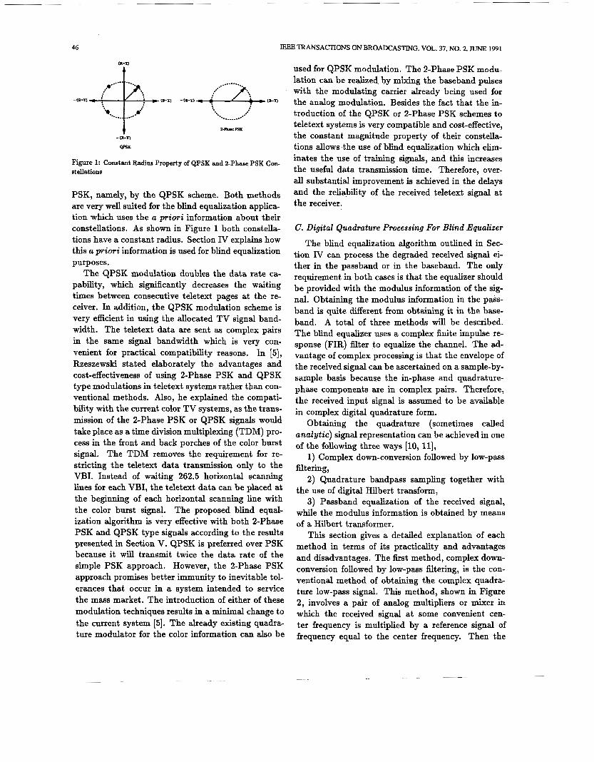
Figure 1: Constant Radius Property of QPSK and 2-Phase PSK Con- stellations
PSK, namely, by the QPSK scheme. Both methods are very well suited for the blind equalization applica- tion which uses the a priori information about their constellations. As shown in Figure 1 both constella- tions have a constant radius. Section IV explains how this a priori information is used for blind equalization purposes.
The QPSK modulation doubles the data rate ca- pability, which significantly decreases the waiting times between consecutive teletext pages at the re- ceiver. In addition, the QPSK modulation scheme is very efficient in using the allocated TV signal band- width. The teletext data are sent as complex pairs in the same signal bandwidth which is very con- venient for practical compatibility reasons. In [SI, Rzeszewski stated elaborately the advantages and cost-effectiveness of using 2-Phase PSK and QPSK type modulations in teletext systems rather than con- ventional methods. Also, he explained the compati- bility with the current color TV systems, as the trans- mission of the 2-Phase PSK or QPSK signals would take place as a time division multiplexing (TDM) pro- cess in the front and back porches of the color burst signal. The TDM removes the requirement for re- stricting the teletext data transmission only to the VBI. Instead of waiting 262.5 horizontal scanning lines for each VBI, the teletext data can be placed at the beginning of each horizontal scanning line with the color burst signal. The proposed blind equal- ization algorithm is very effective with both 2-Phase PSK and QPSK type signals according to the results presented in Section V. QPSK is preferred over PSK because it will transmit twice the data rate of the simple PSK approach. However, the 2-Phase PSK approach promises better immunity to inevitable tol- erances that occur in a system intended to service the mass market. The introduction of either of these modulation techniques results in a minimal change to the current system [5]. The already existing quadra- ture modulator for the color information can also be
and the reliability of the received teletext signal at the receiver.
C. Digital Quadrature Processing For Blind Equalizer
The blind equalization algorithm outlined in Sec- tion IV can process the degraded received signal ei- ther in the passband or in the baseband. The only requirement in both cases is that the equalizer should be provided with the modulus information of the sig- nal. Obtaining the modulus information in the pass- band is quite different from obtaining it in the base- band. A total of three methods will be described. The blind equalizer uses a complex finite impulse re- sponse (FIR) filter to equalize the channel. The ad- vantage of complex processing is that the envelope of the received signal can be ascertained on a sample-by- sample basis because the in-phase and quadrature- phase components are in complex pairs. Therefore, the received input signal is assumed to be available in complex digital quadrature form.
Obtaining the quadrature (sometimes called andyt ic) signal representation can be achieved in one of the following three ways [lo, 111,
1) Complex down-conversion followed by low-pass filtering,
2) Quadrature bandpass sampling together with the use of digital Hilbert transform,
3) Passband equalization of the received signal, while the modulus information is obtained by means of a Hilbert transformer.
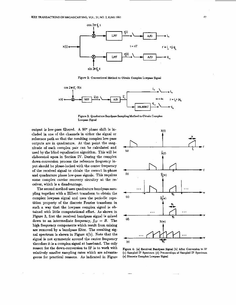
This section gives a detailed explanation of each method in terms of its practicality and advantages and disadvantages. The first method, complex down- conversion followed by low-pass filtering, is the con- ventional method of obtaining the complex quadra ture low-pass signal. This method, shown in Figure 2, involves a pair of analog multipliers or mixer in which the received signal at some convenient cen- ter frequency is multiplied by a reference signal of frequency equal to the center frequency. Then the
EEE TRANSACTIONS ON BROADCASTING, VOL. 37, NO. 2, JUNE 1991 47
cos 2Tr f, t I
r = \ + j a t=nT
Figure 2: Conventional Method to Obtain Complex Lowpass Signal
COS 2r(f,-B)t
I
Figure 3: Quadrature Bandpass Sampling Method to Obtain Complex Lowpass Signal
output is low-pass filtered. A 90" phase shift is in- cluded in one of the channels in either the signal or reference path so that the resulting complex low-pass outputs are in quadrature. At that point the mag- nitude of each complex pair can be calculated and used by the blind equalization algorithm. This will be elaborated upon in Section IV. During the complex down-conversion process the reference frequency in- put should be phase-locked with the center frequency of the received signal to obtain the correct in-phase and quadrature phase low-pass signals. This requires some complex carrier recovery circuitry at the re-' ceiver, which is a disadvantage.
The second method uses quadrature bandpass sam- pling together with a Hilbert transform to obtain the complex lowpass signal and uses the periodic repe- tition property of the discrete Fourier transform in such a way that the lowpass complex signal is ob- tained with little computational effort. As shown in Figure 3, first the received bandpass signal is mixed down to an intermediate frequency, f 1 ~ = B. The high frequency components which result from mixing are removed by a bandpass filter. The resulting sig- nal spectrum is shown in Figure 4(b). Note that the signal is not symmetric around the center frequency therefore it is a complex signal at baseband. The only reason for the down-conversion to IF is to work with relatively smaller sampling rates which are advanta- geous for practical reasons. As indicated in Figure
... , , ... 4 '. W W
t
Figure 4: (a) Received Bandpass Signal (b) After Conversion to IF (e) Sampled IF Spectrum (d) Pre-envelope e€ Sampled IF Spectrum (e) Discrete Complex Lowpass' Signal
48 IEEE TRANSACTIONS ON BROADCASTING, VOL. 37, NO. 2, JUNE 1991
I 4L e-j 2 IrfsT
I I & PASSBAND r(t) 0 t=nT EQUALIZER DECISION
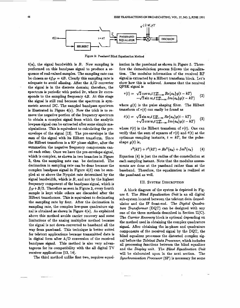
Figure 5: Passband Blind Equalization Method
4(a), the signal bandwidth is B . Now sampling is performed on this bandpass signal to produce a se- quence of real-valued samples. The sampling rate can be chosen as 4fIF = 4B. Clearly this sampling rate is adequate to avoid aliasing. After the A/D converter the signal is in the discrete domain; therefore, the spectrum is periodic with period 27r, where 21r corre- sponds to the sampling frequency 4B. At this stage the signal is still real because the spectrum is sym- metric around DC. The sampled bandpass spectrum is illustrated in Figure 4(c). Now the trick is to re- move the negative portion Qf the frequency spectrum to obtain a complex signal from which the analytic lowpass signal can be extracted after some simple ma- nipulations. This is equivalent to calculating the pre- envelope of the signal [12]. The pre-envelope is the sum of the signal with its Hilbert transform. Since the Hilbert transform is a 90° phase shifter, after the summation the negative frequency components can- cel each other. Once we have the pre-envelope signal, which is complex, as shown in two branches in Figure 3, then the sampling rate can be decimated. The decimation in sampling rate can be done because the complex bandpass signal in Figure 4(d) can be sam- pled at or above the Nyquist rate determined by the signal bandwidth, which is B, and not by the highest frequency component of the bandpass signal, which is f l ~ + B / 2 . Therefore as seen in Figure 3, every fourth sample is kept while others are discarded after the Hilbert transformer. This is equivalent to decimating the sampling rate by four. After the decimation in sampling rate, the complex low-pass quadrature sig- nal is obtained as shown in Figure 4(e). As explained above this method avoids carrier recovery and some limitations of the analog multiplier method because the signal is not down-converted to baseband all the way from passband. This technique is better suited for teletext applications because transmitted data is in digital form after A/D conversion of the received bandpass signal. This method is also very advan- tageous for its compatibility with the all digital TV receiver applications [13, 141.
The third method unlike first two, requires equal-
ization in the passband as shown in Figure 5 . There- fore the demodulation process follows the equaliza- tion. The modulus information of the received RF signal is extracted by a Hilbert transform block. Let's show how this is achieved. Assume that the received QPSK signal is
(2) T ( t ) = fiC0sWctC~=-, Re{ak}g(t - kT)
- f i s h w,t CK-, Im{Uk}g(t - kT) where g( t ) is the pulse shaping filter. The Hilbert transform of ~ ( t ) can easily be found as
(3) $ ( I ! ) = f i s h W J ! ~ ~ - , Re{ak}g(t - kT)
+fi cos W c t Cfp=-, Im{ab}g(t - kT) where +(t ) is the Hilbert transform of ~ ( t ) . One can verify that the sum of squares of r ( t ) and +(t ) at the optimum sampling instants, t = kT, for the pulse- shape g ( t ) is,
r 2 ( k ~ ) + f 2 ( k ~ ) = Re2{ar} + Im2{ak} (4)
Equation (4) is just the radius of the constellation at each sampling instant. Note that the modulus assess- ments are done at the passband rather than at the baseband. Therefore, the equalization is realized at the passband as well.
111. SYSTEM DESCRIPTION
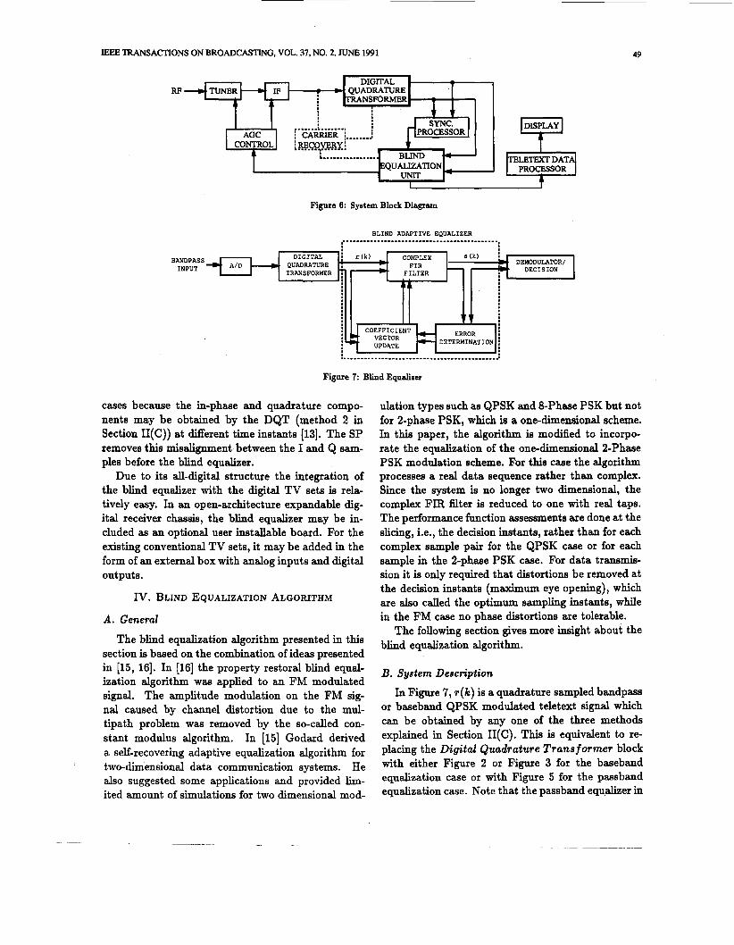
A block diagram of the system is depicted in Fig- ure 6. The Blind Equalization Unit is an all digital sub-system located between the teletext data demod- ulator and the IF front-end. The Digital Quadra- ture fiansfomzer (DQT) can be designed with any one of the three methods described in Section II(C). The Cam'er Recovery block is optional depending on the method used in obtaining the complex quadrature signal. After obtaining the in-phase and quadrature components of the received signal by the DQT, the blind equalizer processes the distorted complex sig- nal before the Teletezt Data Processor, which includes all processing functions between the blind equalizer and the Display unit. The Blind Equalization Unit will be elaborated upon in the next section. The Synchronization Processor (SP) is necessary for some
IEEE lRANSACTIONS ON BROADCASTING, VOL. 37, NO. 2, JUNE 1991 49
DIGITAL - i r(k) COMPLEX . QUADRATURE > FIR TRANSFOF34ER 7 )' FILTER
RP
I
I
:
Figure 6: Syetem Block Diagram
A A
I I
I
I
Vl COEFFICIENT ERROR
c. VECTOR
BANDPASS INPUT
*
BLIND ADAPTIVE EQUALIZER .............................................
DETERMINATION : UPDATE - c
DISPLAY
PROCESSOR
Figure 7: Blind Equalizer
cases because the in-phase and quadrature compo- nents may be obtained by the DQT (method 2 in Section II(C)) at different time instants 1131. The SP removes this misalignment between the I and Q sam- ples before the blind equalizer.
Due to its all-digital structure the integration of the blind equalizer with the digital TV sets is rela- tively easy. In an open-architecture expandable dig- ital receiver chassis, the blind equalizer may be in-
dation types such as QPSK and 8-Phase PSK but not for 2-phase PSK, which is a one-dimensional scheme. In this paper, the algorithm is modified to incorpo- rate the equalization of the one-dimensional 2-Phase PSK modulation scheme. For this case the algorithm processes a real data sequence rather than complex. Since the system is no longer two dimensional, the complex FIR filter is reduced to one with real taps. The performance function aesessments are done at the
cluded as an optional user installable board.-For the existing conventional TV sets, it may be added in the form of an external box with analog inputs and digital outputs.
slicing, i.e., the decision instants, rather than for each complex sample pair for the QPSK case or for each sample in the 2-phase PSK case. For data transmis- sion it is only required that distortions be removed at the decision instants (maximum eye opening), which are also called the optimum sampling instants, while in the FM case no phase distortions are tolerable.
The following section gives more insight about the blind equalization algorithm.
IV. BLIND EQUALIZATION ALGORITHM
A . General
The blind equalization algorithm presented in this section is based on the combination of ideas presented in [15, 161. In [16] the property restoral blind equal- ization algorithm was applied to an FM modulated signal. The amplitude modulation on the FM sig- nal caused by channel distortion due to the mul- tipath problem was removed by the so-called con- stant modulus algorithm. In [15] Godard derived a self-recovering adaptive equalization algorithm for two-dimensional data communication systems. He also suggested some applications and provided lim- ited amount of simulations for two dimensional mod-
B. System Description
In Figure 7 , r ( k ) is a quadrature sampled bandpass or baseband QPSK modulated teletext signal which can be obtained by any one of the three methods explained in Section II(C). This is equivalent to re- placing the Digital Quadrature Trans f mmer block with either Figure 2 or Figure 3 for the baseband equalization case or with Figure 5 for the passband equalization case. Note that the passband equalizer in
50 'RANSACTIONS ON BROADCASTING, VOL. 37, NO. 2, JUNE 1991
Figure 5 should be replaced with the blind adaptive equalizer in Figure 7. For the 2-Phase PSK modu- lation, quadrature sampling is not needed since the data is one-dimensional. If passband equalization is desired, the demodulation takes place after the equal- ization [16]. Otherwise, the blind equalizer processes the baseband analytic signal and removes the distor- tion. The derivation of the algorithm presented in this section is general and applies to both passband and baseband equalizations.
The distorted analytic input signal, ~ ( k ) , is applied to a finite impulse response filter whose complex co- efficients are iteratively adjusted by a simple gradient steepest descent algorithm to minimize the presence of the unwanted signal components at the filter out- put. Equivalently, for the 2-Phase PSK case the same process is repeated with a real coefficient FIR filter. However, for the sake of generality, the derivation of the algorithm will be given using complex arithmetic.
Given the discrete-time, degraded complex input waveform r(k), the complex filter output s(k) may be written in vector notation as,
5(k) = rt(k)w(k) (5)
where r(k) is a window of data,
r(k) = [~(k) ~ ( k - 1) . . . T ( k - N + 1)It. (6)
N is the number of taps in the complex FIR filter. The adjustable complex FIR tap weights are given by the vector,
w(k) = [WO@) W l ( k ) * * * W N - l ( k ) l t . ( 7 )
The index k indicates that the vector coefficients are updated at each sampling instant. However, this in- dex can be held to any arbitrary number of samples depending on how fast it is desired to update the al- gorit hm .
Since the blind equalizer does not have a training signal, the performance function to be optimized by the steepest descent rule should be only a function of input signal properties and the distorted received signal [16]. In our case the objective is to restore s(k) to a constant modulus signal if it is at passband or to a constant magnitude constellation if it is at baseband. Keeping these facts in mind the performance, or so- called cost function to be minimized is found to be
J@) = E(ls (k)JP - Mp)2 (8) where E ( - ) is the expected value operator. The role of constant Mp will be explained shortly. The minimiza- tion of J@) leads to minimization of the IS1 caused
by multipath distortion [15]. Note that the perfor- mance function (8) is evaluated and the filter taps are updated at the decision, i.e., optimum sampling instances. For mathematical and practical reasons the parameter p is restricted to '1' or '2' [17]. In our case p was chosen to be '2', therefore, (8) becomes,
J = E(ls(k)12 - M ) 2 (9) M is chosen as the constant amplitude of the sig- nal for the equalization of constant modulus bandpass signals such as FM and as the radius of the constel- lation for the PSK and QPSK modulation schemes. Intuitively minimization of (9) restores the s ( k ) to a magnitude or modulus of M because deviations of s(k) from M are penalized by the adaptive algorithm as will be explained in the next section.
C. Algorithm
The equalizer tap gains are adjusted according to the classical gradient steepest descent algorithm:
~ ( k + 1) = ~ ( k ) - P v w Jk (10)
where ~ ( k ) is the set of complex FIR filter coefficients used to generate output s(k), 1.1 is the step size or so- called learning rate, and vw is the gradient operator with respect to the elements of the filter coefficient vector w.
Using complex matrix calculus, it can be shown that the gradient of J with respect to the weight vec- tor g is given by
v W J = 2E{(/s(k)l2 - M ) - ~ W [ ~ % * T ' U ] }
= 4E{(ls(k)(2 - M ) -r*(k) * r"k)w(k)} = 4 E { ( l ~ ( k ) 1 ~ - M ) -~(k)r*(k)}
(11) where h and * indicate the conjugate transpose and conjugate operations respectively. The update equa- tion is simplified by replacing the expected value with the instantaneous gradient yielding,
vw J = [ls(k)I2 - MI - ~(k)r*(k). (12)
Also the factor 4 in (11) is removed assuming that the performance function J in (8) is scaled by 4. Substi- tuting equation (12) into (10) yields the desired algo- rithm,
~ ( k + 1) = ~ ( k ) - ~ { [ l s ( k ) \ ~ - M]s(k ) r* (k ) } . (13)
To simplify the notation, we define e ( k ) as
E(k) {(s(k)12 - M } s ( k ) . (14)
Then the updating algorithm can be compactly writ-
IEEE TRANSACTIONS ON BROADCASTING, VOL. 37, NO. 2, JUNE 1991 51
QUADRATURE MODULATOR
NOISE ? DEMODULATOR
TELETEXT PULSE 2-PHASE PSK VSB XMIT SHAPING MODULATOR FILTER
NOISE =-+ BLIND
(b) EQUALIZER DEMODULATOR
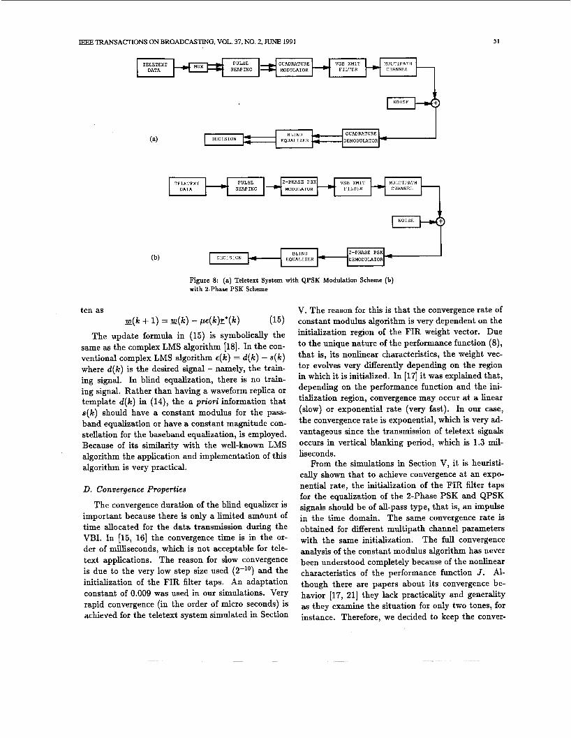
Figure 8: (a) Teletext System with QPSK Modulation Scheme (b) with 2-Phase PSK Scheme
ten as - w(k + 1) = w(k) - pe(k)r*(k) (15)
The update formula in (15) is symbolically the same as the complex LMS algorithm [18]. In the con- ventional complex LMS algorithm E(k) = d(k) - s(k) where d(k) is the desired signal - namely, the train- ing signal. In blind equalization, there is no train- ing signal. Rather than having a waveform replica or template d(k) in (14), the a priori information that s(k) should have a constant modulus for the pass- band equalization or have a constant magnitude con- stellation for the baseband equalization, is employed. Because of its similarity with the well-known LMS algorithm the application and implementation of this algorithm is very practical.
D. Convergence Properties
The convergence duration of the blind equalizer is important because there is only a limited ambunt of time allocated for the data transmission during the VBI. In [15, 161 the convergence time is in the or- der of milliseconds, which is not acceptable for tele- text applications. The reason for slow convergence is due to the very low step size used (2-l') and the initialization of the FIR filter taps. An adaptation constant of 0.009 was used in our simulations. Very rapid convergence (in the order of micro seconds) is achieved for the teletext system simulated in Section
V. The reason for this is that the convergence rate of constant modulus algorithm is very dependent on the initialization region of the FIR weight vector. Due to the unique nature of the performance function (8), that is, its nonlinear characteristics, the weight vec- tor evolves very differently depending on the region in which it is initialized. In [17] it was explained that, depending on the performance function and the ini- tialization region, convergence may occur at a linear (slow) or exponential rate (very fast). In our case, the convergence rate is exponential, which is very ad- vantageous since the transmission of teletext signals occurs in vertical blanking period, which is 1.3 mil- liseconds.
From the simulations in Section V, it is heuristi- cally shown that to achieve convergence at an expo- nential rate, the initialization of the FIR filter taps for the equalization of the 2-Phase PSK and QPSK signals should be of A-pass type, that is, an impulse in the time domain. The same convergence rate is obtained for different multipath channel parameters with the same initialization. The full convergence analysis of the constant modulus algorithm has never been understood completely because of the nonlinear characteristics of the performance function J. Al- though there are papers about its convergence be- havior [17, 211 they lack practicality and generality as they examine the situation for only two tones, for instance. Therefore, we decided to keep the conver-
52
BER
IEEE TRANSACTIONS ON BROADCASTING, VOL. 37, NO. 2, JUNE 1991
BER
0.0 1.6 3.2 4.8 6.4 8.0 0.0 1.6 3.2 4.8 6.4 8.0
(a) s m (a) (b) STJm (a)
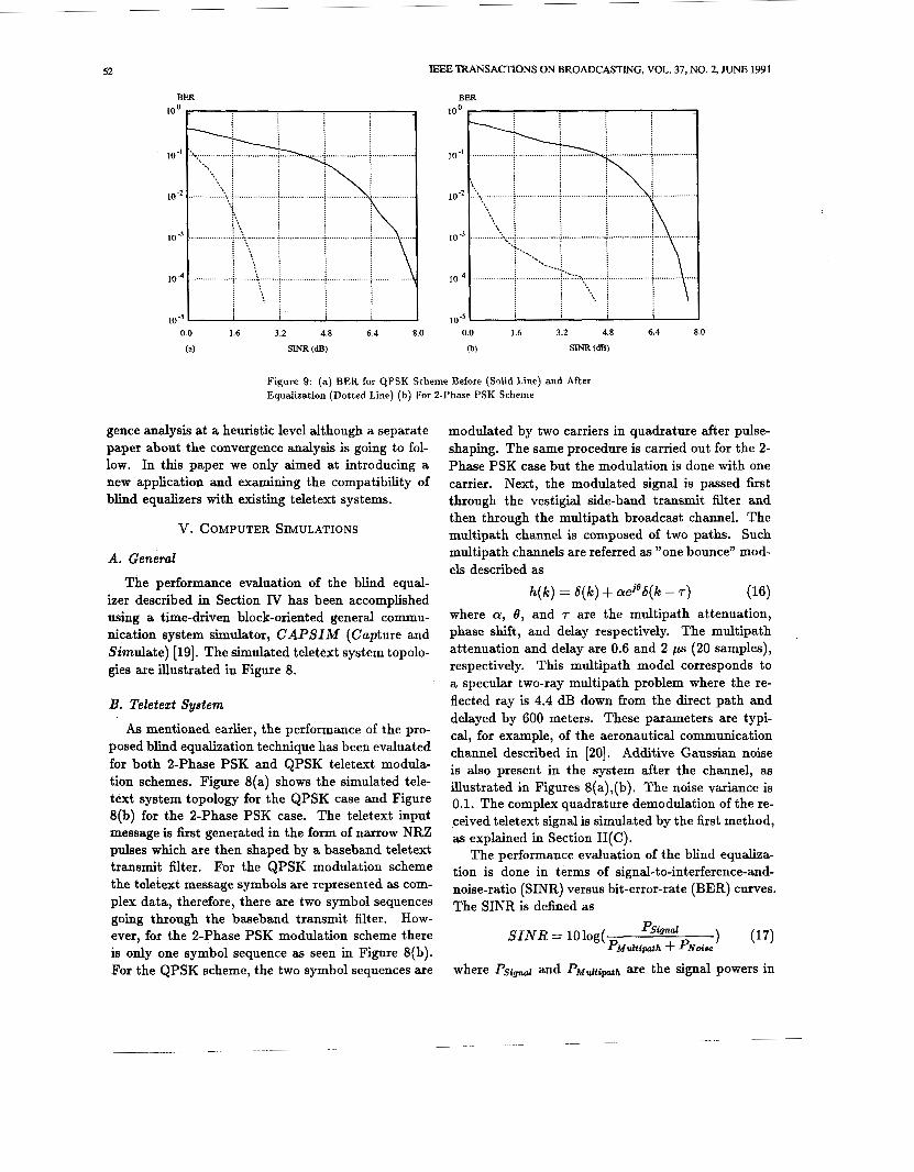
Figure 9: (a) BER for QPSK Scheme Before (Solid Line) and After Equalization (Dotted Line) (b) For 2-Phase PSK Scheme
gence analysis at a heuristic level although a separate paper about the convergence analysis is going to fol- low. In this paper we only aimed at introducing a new application and examining the compatibility of blind equalizers with existing teletext systems.
V. COMPUTER SIMULATIONS
A . General
The performance evaluation of the blind equal- izer described in Section IV has been accomplished using a time-driven block-oriented general commu- nication system simulator, CAPSIM (Capture and Simulate) [19]. The simulated teletext system topolo- gies are illustrated in Figure 8.
B. Teletext System
As mentioned earlier, the performance of the pro- posed blind equalization technique has been evaluated for both 2-Phase PSK and QPSK teletext modula- tion schemes. Figure 8(a) shows the simulated tele- text system topology for the QPSK case and Figure 8(b) for the 2-Phase PSK case. The teletext input message is first generated in the form of narrow NRZ pulses which are then shaped by a baseband teletext transmit filter. For the QPSK modulation scheme the teletext message symbols are represented as com- plex data, therefore, there are two symbol sequences going through the baseband transmit filter. How- ever, for the 2-Phase PSK modulation scheme there is only one symbol sequence as seen in Figure 8(b). For the QPSK scheme, the two symbol sequences are
modulated by two carriers in quadrature after pulse- shaping. The same procedure is carried out for the 2- Phase PSK case but the modulation is done with one carrier. Next, the modulated signal is passed first through the vestigial side-band transmit filter and then through the multipath broadcast channel. The multipath channel is composed of two paths. Such multipath channels are referred as "one bounce" mod- els described as
h(k) = ~ ( k ) + aejeS(k - T )
where a, 8 , and T are the multipath attenuation, phase shift, and delay respectively. The multipath attenuation and delay are 0.6 and 2 ps (20 samples), respectively. This multipath model corresponds to a specular two-ray multipath problem where the re- flected ray is 4.4 dB down from the direct path and delayed by 600 meters. These parameters are typi- cal, for example, of the aeronautical communication channel described in [20]. Additive Gaussian noise is also present in the system after the channel, as illustrated in Figures 8(a),(b). The noise variance is 0.1. The complex quadrature demodulation of the re- ceived teletext signal is simulated by the first method, as explained in Section II(C).
The performance evaluation of the blind equaliza- tion is done in terms of signal-to-interference-and- noise-ratio (SINR) versus bit-error-rate (BER) curves. The SINR is defined as
(16)
1 (17) SINR = lOlog( PSignal
P M d t i p n t h + PNoise
where psig, and pM,&ipnth are the signal powers in
53
I I I I
EEE TRANSACTIONS ON BROADCASTING, VOL. 37, NO. 2, JUNE 1991
2.5 r ., 2.5
..................
..................
..................
..................
...........................................
...... +
0.5 1.5 2.5 -2.5 -1.5 -0.5 0.5 1.5 2 3 -2.5 -1.5 -0.5
(a) (b)
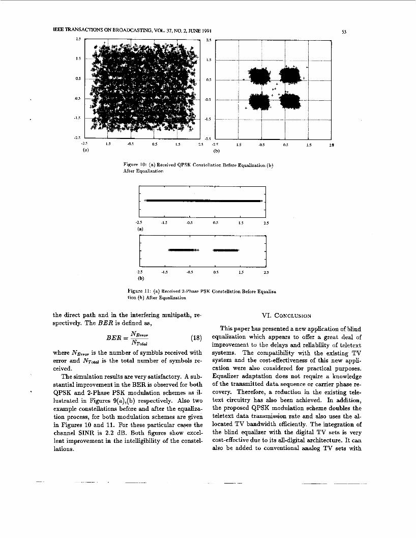
Figure 10: (a) Received QPSK Constellation Before Equalization (b) After Equalization
-2.5 -1.5 -0.5 0.5 1.5 2.5
(a)
-2.5 3 -1.5 -0.5 0.5 1.5 2.5
(b)
Figure 11: (a) Received 2-Phase PSK Constellation Before Equaliza- tion (b) After Equalization
the direct path and in the interfering multipath, re- spectively. The B E R is defined as,
NETT07 B E R = - NTotal
where is the number of symbols received with error and N ~ d d is the total number of symbols re- ceived.
The simulation results are very satisfactory. A sub- stantial improvement in the BER is observed for both QPSK and 2-Phase PSK modulation schemes as il- lustrated in Figures 9(a),(b) respectively. Also two example constellations before and after the e,qualiza- tion process, for both modulation schemes are given in Figures 10 and 11. For these particular cases the channel SINR is 2.2 dB. Both figures show excel- lent improvement in the intelligibility of the constel- lations.
.
VI. CONCLUSION
This paper has presented a new application of blind equalization which appears to offer a great deal of improvement to the delays and reliability of teletext systems. The compatibility with the existing TV system and the cost-effectiveness of this new appli- cation were also considered for practical purposes. Equalizer adaptation does not require a knowledge of the transmitted data sequence or carrier phase re- covery. Therefore, a reduction in the existing tele- text circuitry has also been achieved. In addition, the proposed QPSK modulation scheme doubles the teletext data transmission rate and also uses the al- located TV bandwidth efficiently. The integration of the blind equalizer with the digital TV sets is very cost-effective due to its all-digital architecture. It can also be added to conventional analog TV sets with
54 IEEE TRANSACTIONS ON BROADCASTING, VOL. 37, NO. 2, JUNE 1991
a simple A/D converter. The performance of the proposed blind equalizer has been evaluated in the presence of a multipath broadcast channel. Simula- tions have shown that substantial improvements are observed in the bit-error-rates for both 2-Phase PSK and QPSK modulation schemes.
VI. REFERENCES
[l] M. Obara, T. Uehara, S. Makino, T. Hirata, K. Ohzeki, J. Murakami, “A Digital Time Domain Equalizer”, IEEE Transactions on Consumer E[ectronics, Vol. CE-28, No. 3, August 1982, pp. 447-452.
1151 D. N. Godard, “Self-Recovering Equalization and Carrier Tracking in Two-Dimensional Date Communication Sys- tems,” IEEE !l“nsactions on Communications, Vol. COM- 28, No. 11, November 1980, pp. 1867-1875.
[16] J. R. Treichler and B. G. Agee, “A New Approach to Multipath Correction of Constant Modulus Signals,” IEEE Transactions on Acoustics, Speech, and Signal Processing, Vol. ASSP-31, NO. 2, April 1983, pp. 459-472.
[17] M. G. Larimore and J. R. Treichler, “Convergence Behavior of the Constant Modulus Algorithm,” ICASSP 1989 Boston, Vol. 1, pp. 13-16.
[18] B. Widrow, J. McCool, M. Ball, “The Complex LMS Algo- rithm,” Proceedings of the IEEE, April 1975, pp. 719-720.
[2] E. Arnon, “An Adaptive Equalizer for Television Channels”, IEEE Transactions on Communications, Vol. COM-17, No. 6, December 1969, p. 726.
[19] R. A. Nobakht, p. W. Pate, S. H. Ardalan, “CAPSIM: A Graphical Simulation Tool for Communication Systems,” GLOBECOM, 1988, pp. 1692-1696.
[3] S. Makino et al., “A Fully Automatic Ghost Canceller,” IEEE Transactions on Consumer Electronics, Vol. CE-24, No. 3, August 1978, pp. 267.
[20] G. S. Takhar and S. C. Gupta, “Discrete Estimation of Con- tinuous Angle Modulated Channels for Aeronautical Com- munication,” IEEE Transactions on Communications, Vol. COM-24, March 1976. [4] K. B. Benson, “Television Engineering Handbook,” Mc
Graw-Hill, 1980. [21] J. R. Treichler and M. G. Larimore, “The Tone Capture Properties of CMA-Based Interference Suppressors,” IEEE Transactions on Acoustics, Speech, and Signal Processing, Vol. ASSP-33, No. 4, August 1985.
[5] T. Rzeszewski, “A New Teletext Channel,” IEEE Transac- tions on Communications, Vol. COM-29, No. 2, February 1981, pp. 110-116.
161 B. G. Agee, “The Property-Restoral Approach to Blind Adaptive Signal Extraction,” Ph. D Dissertation , Univer- sity of California, Davis, 1989.
[7] S. U. H. Qureshi, “Adaptive Equalization,” Proceeding of the IEEE, Vol. 73, No. 9, September 1985, pp. 1349-1387.
[81 M. Sablatash, K. W. Moreland, R. K. Tiedemann, “Model- ing Broadcast Teletext Systems for Analysis and Computer Simulation Studies,” IEEE Transactions on Communica- tions, Vol. COM-35, No. 10, October 1987, pp. 991-1004.
[9] E. S. Sousa and S. Pasupathy, “Pulse Shape Design for Tele- text Data Transmission,” IEEE Bansactions on Communi- cations, Vol. COM-31, NO. 7, July 1983, pp. 871-878.
[lo] D. W. Rice and K. H. Wu, “Quadrature Sampling With High Dynamic Range,” IEEE Transactions on Aerospace and Electronic Systems, Vol. AES-18, No. 4, November 1982, pp. 736-739.
C. M. Rader, “A Simple Method for Sampling In-Phase and Quadrature Components,” IEEE Transactions on Aerospace and Electronic Systems, Vol. AES-20, No. 6, November 1984, pp. 821-824.
S. Haykin, “Communication Systems,” John Wiley and Sons, 1978.
G. J. Saulnier et al., “A VLSI Demodulator for Digital R F network Applications: Theory and Results,” IEEE Journal on Selected Areas in Communications, Vol. 8, No. 8, October 1990, pp. 1500-1511.
Jeyhan Karaoguz was born in Ankara, Tiirkiye, in 1966. He re- ceived the B.Sc degree in electri- cal engineering from the Middle East Technical University, Ankara, in 1988, and the M.$c degree from North Carolina State University, Raleigh, in 1989. He is currently studying towards the Ph.D degree in electrical engineering at North Carolina State University.
His research interests include blind adaptive equalization, appli- cations of neural networks to signal
processing and digital communications, and mobile communications. Mr. Karaohz is a member of Eta Kappa Nu, Phi Kappa Phi, and Pi Mu Epsilon.
Saean Houston Ardalan was born in Tehran, Iran, on March 20, 1956. He received the B.Sc., M.Sc., and Ph.D. degrees in electrical and computer engineering from North Carolina State University, Raleigh, in 1977, 1979, and 1983, respec- tively.
In August 1983 he joined the Center for Communications and Signal Processing (CCSP) at NC State as a Research Engineer. He is currently an Associate Professor of Electrical and Computer Engi- _ _
neering. He is the Principal Investigator of the Physical Layer in the co”unications and Networking BTea in ccsp. Among his research interests are digital communications, adaptive digital signal process- ing, inchding blind equalization, electromagnetic radiation, and archi- tectures for real-time image formation from synthetic aperture radar. He is also a member of Sigma Xi.
[14] H. Samueli and B. C. Wong, “A VLSI Architecture for a High-speed All-Digital Quadrature Modulator and Demod- ulator for Digital Radio Applications,” IEEE Journal on Selected Areas in Communications, Vol. 8, NO. 8, October 1990, pp. 1512-1519.