Embed Size (px)
Citation preview

User Guide:FS Series 3 PV ModuleNorth America
User Guide
PD-5-200-03 Black 4 NA | 02811_UG_NA_BLACK_01SEP13
REV 3.1

FS Series 3 PV Module User Guide—North America | Page i of 14
PD-5-200-03 Black 4 NA | REV 3.1 | 02771_UG_NA_Black_01SEP13
Table of Contents
1 Introduction ...................................................................................................................................................................1
1.1 Before You Begin ..............................................................................................................................................1
1.2 Key Product Features .......................................................................................................................................1
1.3 Safety ...............................................................................................................................................................2
2 Regulatory Compliance ..................................................................................................................................................3
3 ElectricalSpecifications .................................................................................................................................................4
3.1 SystemDeratingFactors...................................................................................................................................4
4 Installation .....................................................................................................................................................................5
4.1 Mounting ..........................................................................................................................................................5
4.2 Location,AngleandTilt ....................................................................................................................................6
4.3 ModuleShadingConsiderations .......................................................................................................................6
4.4 ElectricalInterconnection ................................................................................................................................7
5 MechanicalSpecifications&Drawings.........................................................................................................................10
6 ProperOperatingConditions .......................................................................................................................................11
7 Service .........................................................................................................................................................................12
8 WarrantyTerms&Conditions ......................................................................................................................................12
9 Notice ..........................................................................................................................................................................13
10 Revision History ...........................................................................................................................................................14

FS Series 3 PV Module User Guide—North America | Page 1 of 14
PD-5-200-03 Black 4 NA | REV 3.1 | 02771_UG_NA_Black_01SEP13
1 Introduction
FirstSolarSeries3PVandSeries3BlackModulesaremanufacturedinstate-of-the-artfacilitiesusingahighlyinnovativeprocessthatrapidlydepositsthinfilmsofsemiconductoronglass.Themoduleshavebeendesignedtohavealongoperatinglifeandhighenergyyield—ifinstalled,operated,andservicedinaccordancewiththeinstructionsinthisUserGuideaswellasintheSystemDesignandApplicationDocument(PD-2-303).FirstSolarSeries3andSeries3BlackPVModulesarefullycompatiblewithoneanother.ThisUserGuidecoversbothFirstSolarSeries3andSeries3BlackPVModules.
1.1 Before You Begin
ThisdocumentprovidesguidelinesandinformationonFirstSolarFSSeries3andSeries3BlackPVModulesforsystemdesigners,installers,andmaintenancepersonnel.ReadthisUserGuidethoroughlybeforebeginninganyworkrelatedtotheinstallation,operation,ormaintenanceoftheFirstSolarSeries3andSeries3BlackPVModule.Onlyqualifiedpersonnelshouldinstall,operate,ormaintainaPVmoduleorsystem.
Failuretofollowinstallationandhandlinginstructionsmayresultininjury.
Failuretomaintainproperoperatingconditionrequirementsforthemoduleswillvoidthewarranty(refertoFirstSolarFSSeriesModuleWarrantyTerms&ConditionsPD-5-102).
ThisguidepertainstomodulesinstalledwithinNorthAmericaonly.IfamoduleisbeinginstalledoutsideofNorthAmerica,contactFirstSolarorvisitwww.firstsolar.comfortheUserGuideappropriateforothergeographicareas.
Keep this User Guide for future reference.
Guidelinesrelatedtosystemconstructionarebeyondthescopeofthisdocumentandarenotcoveredinthisdocument.
1.2 Key Product Features
• Highenergyyieldsinreal-worldconditions.
• Sizeandweightthatenablesefficienthandlingandinstallation.
• Easy,quick-connectwiringforfastinterconnection.
• Internationallyrecognizedproductcertifications.
• Ten-yearlimitedmaterial/workmanshipandtwenty-fiveyearlimitedpoweroutputwarrantiesasoutlinedin“FirstSolarFSSeriesModuleWarrantyTerms&Conditions”(PD-5-102).

FS Series 3 PV Module User Guide—North America | Page 2 of 14
PD-5-200-03 Black 4 NA | REV 3.1 | 02771_UG_NA_Black_01SEP13
1.3 Safety
The FS Series 3 PV and Series 3 Black Modules may produce voltage in excess of 70 Volts DC (VDC) and current in excess of 2.2 Amps when exposed to sunlight. A single module could create a lethal shock hazard during hours of daylight, including periods of low light levels. The danger increases as modules are connected together in series and/or parallel.
To avoid fire and/or injury due to ground fault and associated electrical hazards:
• Do not unplug PV module connections while under load. Do not disconnect the module connectors during daylight hours unless the module is in an open circuit condition or all modules in series and parallel are covered with an opaque material, such as a tarp or blanket.
• Repair or replace damaged wires immediately. Keep all array wiring out of reach of non-qualified personnel.
• Do not concentrate light on the module in an attempt to increase power output.
• Never allow the PV array open-circuit voltage to exceed 1000VDC under any condition.
• Replace broken modules immediately.
• Repair any ground faults immediately.
• Do not work on modules or systems when the modules or wiring are wet.
Reverse currents higher than the rated values for a First Solar module (reverse current overload), may result in module failure, including module breakage. Extreme and continuous reverse current overload conditions may cause a fire or create electrical shock hazards. To avoid reverse current overload:
• Maintain equivalent voltage in parallel strings by installing an equal number of modules per string within the same source circuit. Failure to install modules with balanced voltage in parallel strings can result in voltage imbalance.
• Comply with all previously noted practices to prevent and repair ground faults.
Wear safety glasses (ANSI Z87.1-2003) and cut-resistant gloves when working on non-interconnected modules or systems.
Wear electrically rated PPE when working on interconnected modules or system components.

FS Series 3 PV Module User Guide—North America | Page 3 of 14
PD-5-200-03 Black 4 NA | REV 3.1 | 02771_UG_NA_Black_01SEP13
2 Regulatory Compliance
Itistheresponsibilityoftheinstallerand/orsystemintegratortoensurecompliancewithalllocalelectricalcodeswhichmaybeapplicabletotheinstallationanduseofFirstSolarSeries3andSeries3BlackPVModules.
• BeforebeginningthePVsystemdesignandinstallation,contactappropriatelocalauthoritiestodeterminelocalcode,permit,andinspectionrequirements.
• IntheUnitedStates,refertoArticle690oftheNationalElectricalCode(NEC)whichappliesto“PhotovoltaicSystems.”
• ForsystemsinstalledinCanada,installationshallbeinaccordancewithCSAC22.1,SafetyStandardforElectricalInstallations,CanadianElectricalCode,Part1.
FirstSolarFSSeries3andSeries3BlackPVModulesareListedbyaNationallyRecognizedTestLaboratorytoUL1703,thestandard for Flat-Plate Photovoltaic Modules and Panels.
Tomaintainthemodules’applicationasaULListedproduct:
• UseonlycomponentsthathavebeenRecognizedorListedbyUnderwritersLaboratories(UL)fortheirintendedpurpose.
• Ensure the PV array open-circuit voltage does not exceed 1000VDC.
• InstallmoduleswithmountingsystemsthathavebeenevaluatedforULListedapplicationasspecifiedinFirstSolarApplicationNotePD-5-320NA.
• ProtectmodulesfromreversecurrentsinexcessoftheMaximumSeriesFuseratingof3.5AasspecifiedinFirstSolarApplicationNotePD-5-308.
FSSeries3andSeries3BlackPVModulesmeettherequirementsofSafetyClassIIandaretestedandcertifiedperIEC61730ApplicationClassAforamaximumsystemvoltageof1000Vwithmaximumovercurrentprotectionratingof3.5A.
FSSeries3andSeries3BlackPVModulesaretestedandcertifiedperIEC61646foramaximumsystemvoltageof1000V.

FS Series 3 PV Module User Guide—North America | Page 4 of 14
PD-5-200-03 Black 4 NA | REV 3.1 | 02771_UG_NA_Black_01SEP13
3 Electrical Specifications
MODELNUMBERSANDRATINGSATSTC*
Nominal Values FS-382 FS-385 FS-387 FS-390 FS-392 FS-395NominalPower(±5%) PMPP(W) 82.5 85.0 87.5 90.0 92.5 95.0Voltage at PMAX VMPP(V) 48.3 46.4 47.0 47.4 47.7 47.5Current at PMAX IMPP(A) 1.71 1.83 1.86 1.90 1.94 2.00Open Circuit Voltage VOC(V) 60.8 60.5 60.5 60.5 60.5 60.5Short Circuit Current ISC(A) 1.94 1.94 1.99 2.06 2.11 2.17Maximum System Voltage VSYS(V) 1000Maximum Series Fuse ICF(A) 3.5
*AsreceivedandstabilizedratingsatStandardTestCondition(1000W/m2,AM1.525°CCellTemperature)+/-10%
Electricalspecificationsaresubjecttochange.Seethemodulelabelforadditionalelectricalratings.
3.1 SystemDeratingFactors
Undernormalconditions,aphotovoltaicmodulemayexperienceconditionsthatproducemorecurrentand/ormorevoltagethanreportedatStandardTestConditions.Accordingly,whendeterminingcomponentratings,thevalueslistedforopencircuitvoltageshouldbemultipliedbyacalculatedfactorbasedonthelowtemperatureopencircuitvoltagetemperaturecoefficient.RefertoFirstSolarApplicationNotePD-5-435foradditionalinformationonthecalculationofthisvoltagemultiplicationfactor.Valueslistedforcurrentshouldbemultipliedby1.25.RefertoSection690-8oftheNationalElectricalCodeforanadditionalmultiplyingfactorof125percent(80percentderating)whichmaybeapplicableincomputationofmaximumcircuitcurrentforproperconductorsizing.Adjustmentsofthosefactorsmightbeneededtorespectsitespecificclimateconditions.

FS Series 3 PV Module User Guide—North America | Page 5 of 14
PD-5-200-03 Black 4 NA | REV 3.1 | 02771_UG_NA_Black_01SEP13
4 Installation
4.1 Mounting
Physically damaged modules may cause ground faults and associated electrical hazards. To avoid these conditions:
• Handle modules with care during installation, as heavy impact on the front, back, or edges could result in damage to the module. Do not walk or stand on modules.
• Do not stack or carry multiple modules on top of one another after removal from factory packaging to minimize the risk of breakage.
• Do not lift or pull on modules using lead wires or strain relief wire loops to minimize the risk of wire damage.
Do not install the modules in high wind or wet conditions to reduce the likelihood of injury.
Wear safety glasses (ANSI Z87.1-2003) and cut-resistant gloves when working on non-interconnected modules or systems.
Wear electrically rated PPE when working on interconnected modules or system components.
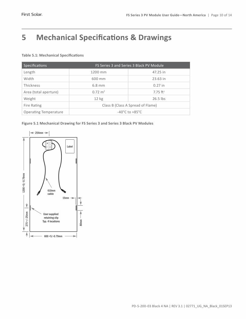
MountingoftheFSSeries3andSeries3BlackPVModuletoasuitablestructurecanbedonebyattachingthemoduledirectlytothestructureusingretainingclips(seeFigure5.1).
ThemoduleisconsideredtobeincompliancewithUL1703onlywhenthemoduleismountedinthemannerspecifiedbythemountinginstructionsspecifiedinFirstSolarApplicationNotePD-5-320NA.
Anymodulewithoutaframe(laminate)shallnotbeconsideredtocomplywiththerequirementsofUL1703unlessthemoduleismountedwithhardwarethathasbeentestedandevaluatedwiththemoduleunderthisstandardorbyafieldInspectioncertifyingthattheinstalledmodulecomplieswiththerequirementsofUL1703.TheFSSeries3andSeries3BlackPVmoduleisaframelesslaminateandisconsideredtobeincompliancewithUL1703onlywhenthemoduleismountedusingapprovedhardwareinthemannerspecifiedbythemountinginstructionsinFirstSolarApplicationNotePD-5-320 NA.
Additionalmountingsystemsmaybeapprovedforuse.RetainingclipdesignsmustmeetthetechnicalrequirementsspecifiedinFirstSolarApplicationNotePD-5-320,andmustbeapprovedforusebyFirstSolarpriortoinstallation.Themountingsystemdesignmustprovideadequatesupportfortheglasslaminatemoduletopreventdamagefromoccurringwhenthemoduleissubjectedtowindloadsof130km/h(80.8mph),withasafetyfactorof3forgustyconditions.Thelocationoftheclipsshallbealongthe1200mm(47.25in)lengthofthemoduleandthecenterpointoftheclipshallbelocatedbetween250mm(9.84in)and300mm(11.81in)fromthemoduleedge.SeeFigure5.1forallowedlocation.Rubbergasketmaterial,orequivalent,mustbeusedbetweenthemoduleandboththeclipandmountingstructuretoprovideadequateprotectionoftheglasslaminatemodule.Nodirectcontactofrigidstructuresispermittedagainstthesurfaceoredges of the glass laminate.
Allmountingstructuresmustprovideaflatplaneforthemodulestobemountedon,andmustnotcauseanytwistorstresstobeplacedonthemodule.
!
!
!
!

FS Series 3 PV Module User Guide—North America | Page 6 of 14
PD-5-200-03 Black 4 NA | REV 3.1 | 02771_UG_NA_Black_01SEP13
Modulesshouldnotbeinstalledinawaythatrestrictsaircirculationtothebacksideofthemodule.Modulesgenerateheatandrequireadequateairflowforcooling.
Installationlocationsandmodulesupportstructuresshouldbeselectedtoensuremodulesandconnectors(openormated)areneversubmersedinstandingwater.FirstSolarmodulesaretestedandcertifiedforapplicationsinvolvingpressuresfromsnow/ice/windupto2400Pa(50.13lb/ft2)whenmountedproperly.Snowdriftscouldresultinanonuniformloadingofthemoduleswhichexceedsthetestedpressure.Ifitisexpectedthatloadswillexceed2400Pa(50.13lb/ft2),itisrecommendedtoclearsnowfrommodules,andensurethatice/thaw/freezecyclesundersnowdriftsdonotresultinexcessivestressesonthe module.
Heavyconstructionandtrenchingshouldbecompletedpriortomoduleinstallationtominimizedebrisanddust.
Ensureanysoilbindingagentsorsaltsusedforon-sitedustcontroldonotspray,splash,ordriftontothesurfaceofthemodules.
TheULapproveddesignloadofFSSeries3andSeries3BlackPVModulesis30lb/ft2(1436Pa).
Maximumallowablepressureonmodulesmaynotexceed2400Pa(50.13lb/ft2)withoutadditionalmodulesupportthatmustbetestedandapprovedbyFirstSolar.
Forrooftopmounting,modulesmustbemountedoverafireresistantroofcoveringratedfortheapplication.Therecommendedminimumstandoffheightis3.25in(82.55mm).ModulesusedinULListedrooftopapplicationsmustbeinstalledwithapprovedmountingsystemsasspecifiedinFirstSolarApplicationNotePD-5-320NA.Ifalternatemountingmeansareemployed,thismayaffecttheListingfireclassratings.Thefireratingofthismoduleisvalidonlywhenmountedinthemannerspecifiedinthemechanicalmountinginstructions.
4.2 Location,AngleandTilt
Tomaximizeperformance,modulesshouldbelocatedinanareathatreceivesdirectsunlightfrommid-morningtomidafternoon(typically9:00a.m.to3:00p.m.).Installationmustavoidlocatingthemoduleswhereshadowsmaybecausedbybuildings,trees,etc.
PVperformancemodelingsoftwareshouldbeusedtodeterminetheoptimumorientationandtiltangleforeachlocation.
Fortiltedfree-fieldapplicationswherethereisrowtorowshading,itisrequiredtoinstallthemodulesinlandscapeorientation.PleaserefertoFirstSolarApplicationNotePD-5-425-03foradditionalinformation.
4.3 ModuleShadingConsiderations
TominimizetheriskofmoduleshadingdamagepleasefollowtheModuleShadingFieldGuidePD-5-366.InstancesofshadingthatwillleadtoavoidedwarrantyincludetheHighRisklisteditemsbelow.
High Risk (Prohibited) Shading
1. Restingoradheringslenderobjects(tools,brooms,clothing,wires,tape)onsunnysideofoperatingmodules,orwithininchesaboveoperatingmodules,especiallywhenshadoworientedparalleltocells,cancreatehighriskofundesirableshading.

FS Series 3 PV Module User Guide—North America | Page 7 of 14
PD-5-200-03 Black 4 NA | REV 3.1 | 02771_UG_NA_Black_01SEP13
2. Fixedobjectswithin~5-7feetaboveoperatingmodulesthatcastashadowoverthelongdimensionofthecellshouldbeavoided.Closeobjectslikeposts,ropes,signs,fences,orequipmentcanbegintoincreaseriskofpartialshadingoffullcellswhennearerthan~5-7feetfromthesunny-sideofoperatingmodule.
3. Workingcontinuouslywithoutstretchedarmsortoolsoveroperatingmodulescancreatehighriskofundesirableshading.
4. Asupportframeormountingmethodontheshortedge(s)ofmodulesthatfullyshadestheentirelengthofacell(eitherpartiallyorcompletely)cancreateahighriskofundesirableshading.
5. Cleaningapparatuses,includingcleaningrobotsandothermechanismsthattraversethemodulerepeatedlywhilethesystemisoperating(unlessevaluatedandapprovedbyFirstSolar).
4.4 ElectricalInterconnection
FirstSolarFSSeries3andSeries3BlackPVModulesarepre-configuredwithindustrystandardconnectorsthatare“touchproof”withalllivepartsprotectedagainstaccidentalcontactandprotectedagainstpolarityreversal.TheconnectorsareUVandweatherresistantfrom–40°Cto+90°C,andratedfor1000VDCand30A(minimum,beforederatingforambienttemperature).
Damaged wires, connectors, or junction boxes may cause ground faults, and associated electrical hazards, including electrical shock. To avoid these conditions:
• Protect unmated connectors from dust and moisture by using sealing caps (not provided, available from connector manufacturer).
• Limit module connectors to 10 or fewer plug cycles.
• Do not pull lead wires tight at any time. After installation, the connected wire must not be under stress or tension.
• Do not use junction box assembly or lead wire strain relief loops to secure excess wire or to bear weight in excess of a module’s own wire and mated connector pair.
• Connector bodies and cables should not be tightly secured at both ends to any mounting structure to allow for thermal expansion and contraction.
• Secure wire or connected components so that no loose wires or components are hanging within 1.5 feet (0.46m) of the ground in free field applications, and so that wire/components are hanging clear of roof coverings or pooled water in rooftop applications.
• Ensure connectors are fully mated.
• Ensure wire securement methods, such as use of cable ties, do not damage wire insulation. The minimum module lead wire bend radius is 5 times wire diameter. Observe minimum bend radius specifications on all other PV system wiring.
• Ensure wires are not in contact with sharp edges of the mounting structure to avoid abrading the wire sheath.
• Inspect and maintain wire management requirements over the life of the plant.
!

FS Series 3 PV Module User Guide—North America | Page 8 of 14
PD-5-200-03 Black 4 NA | REV 3.1 | 02771_UG_NA_Black_01SEP13
Modules with different FS Series numbers (i.e. FS 2 vs. FS 3) have significantly different electrical operating characteristics and should not be interconnected within the same inverter to prevent power output loss and voltage imbalance conditions that may create the risk of reverse current overload.
FSSeries3andSeries3Blackmodulesareelectricallycompatible,butmayvaryinmoduleconnectortype.Certaincertifyingbodiesmaynotcertifyinterconnectionofthesedifferentconnectortypes.Inthesecases,module-moduleandmodule-harnessconnectionsmusteitherbelikeforlikesuppliersoradaptercableconnectionswouldbeneeded.
Moduletomoduleandmoduletoharnessinterconnectionisadvisedtobedonebetweensamemanufacturerandtypeofconnectors.TheFirstSolarmodulewarrantyisnotaffectedbytheinterconnectionofdifferentsupplierconnectors,however,FirstSolarcannotguaranteethatdifferentconnectortypeswillbemateableineveryconnectioninstance.
Componentsusedtointerconnectthemodulesmustbecompatiblewiththeconnectors,andprovidepropersystemoperationandfaultprotectionasrequiredbyanyapplicablecodes.Fieldwiringmustberatedfor90°C,andbeofatypeapprovedforuseinaccordancewiththeNEC.
WhenconnectingFirstSolarFSSeries3and/orSeries3BlackPVModulesinaseriesstring,ensurethatthesystemdesignvoltagelimitisnotexceeded.For1000VDCapplications,thisistypicallyensuredbylimitingseriesstringsto15modulesorless.For600VDCapplications,thisistypicallyensuredbylimitingseriesstringsto9modulesorless.
FSSeries3andSeries3BlackPVModulesaredesignedforinterconnectionwithgrid-tiePVinverters.Foroff-gridapplications,modulesmustbecoupledwithmaximumpowerpointtracking(MPPT)chargecontrollersorotherwisemaintainedattheirmaximumpowerpoint.AllinvertersmustmeetthetechnicalrequirementsspecifiedinFirstSolarApplicationNotePD-5-310andmustbeapprovedformodulecompatibilitybyFirstSolarpriortoinstallation.Whenconnectingmodulesormodulestringsinseriesensureinverterratingsareappropriate.
Opencircuitexposuremayacceleratemoduleefficiencylossandshouldthereforebeminimized.FirstSolarrequiresthatmodulesnotbeoperatedinopencircuitconditionsformorethanninety(90)cumulativedaystoavoidapotentialreductionin energy output over the life of the modules.
Modulesmustnotbeoperatedundershortcircuitconditionsforextendeddurations.Shortcircuitoperationisnotanapprovedmitigationtechniqueforopencircuitexposure.
4.4.1 Grounding Method
PertherequirementsofUL1703,amodulewithexposedconductivepartsisconsideredtobeincompliancewithUL1703onlywhenitiselectricallygroundedinaccordancewiththeinstructionspresentedandtherequirementsoftheNationalElectrical Code.
FirstSolarFSSeries3andSeries3BlackPVModuleshavenoexposedconductivesurfacesanddonotrequireequipmentgroundingaslongasacliplengthof100mmforastandard4clipmountingisnotexceeded.IntheU.S.,themountingstructuremustbegroundedpertherequirementsoftheNEC,sections250and690.
FirstSolarrecommendsnegativepoleDCelectricalsystemgroundingforlargeutilityscalesystems.
!

FS Series 3 PV Module User Guide—North America | Page 9 of 14
PD-5-200-03 Black 4 NA | REV 3.1 | 02771_UG_NA_Black_01SEP13
4.4.2 Overcurrent Protection
FSSeries3andSeries3Blackmoduleshaveamaximumseriesfuseratingof3.5AasdefinedbyUL1703testmethods.
FSSeries3andSeries3Blackmoduleshaveamaximumovercurrentprotectionratingof3.5AasdefinedbyIEC61730testmethods.
PVsystemsshouldbedesignedtocomplywithandprovidemoduleovercurrentprotectionconsistentwithlocalcodesasappropriatefortheintendedapplicationclassofthesystem.
PleaserefertoFSApplicationNotePD-5-308foradditionalinformationonmoduleovercurrentprotection.
FS Series 3 PV Module User Guide—North America | Page 10 of 14
PD-5-200-03 Black 4 NA | REV 3.1 | 02771_UG_NA_Black_01SEP13
5 Mechanical Specifications & Drawings
Table 5.1: Mechanical Specifications
Specifications FS Series 3 and Series 3 Black PV Module
Length 1200 mm 47.25 in
Width 600 mm 23.63 in
Thickness 6.8 mm 0.27 in
Area(totalaperture) 0.72 m2 7.75ft2
Weight 12 kg 26.5lbs
FireRating ClassB(ClassASpreadofFlame)
OperatingTemperature -40°Cto+85°C
Figure 5.1 Mechanical Drawing for FS Series 3 and Series 3 Black PV Modules

FS Series 3 PV Module User Guide—North America | Page 11 of 14
PD-5-200-03 Black 4 NA | REV 3.1 | 02771_UG_NA_Black_01SEP13
6 Proper Operating Conditions
Theproperoperatingconditionrequirementslistedbelowmustbemaintained.
Important: Failure to maintain proper operating condition requirements for the modules will void the warranty (refer to First Solar FS Series Module Warranty Terms & Conditions PD-5-102).
Requirements:
• FirstSolarrequiresinstallerstousecommerciallyreasonableeffortstogrid-connectthemodulesassoonaspracticabletopreventopencircuitexposureortousemitigationtechniques(resistiveloadbanks)tomaintainconditionsequivalenttonormalloadedmaximumpowerpoint(MPP)operation.FirstSolarmustbenotifiedinwritingpriortoexceeding90daysofcumulativemoduleoperationinopencircuitconditions.Uponconclusionofopencircuitexposure,thisnotificationmustbesupplementedtoreporttotaltimeinopencircuitonaperinverterbasis.FailuretocompletethisnotificationinatimelymannermayvoidmodulewarrantycoverageattheelectionofFirstSolar.FirstSolarreservestherighttomodifymodulepoweroutputwarrantycoverageintheevent90dayopencircuit exposure is exceeded.
• Shortcircuitoperationispermittedonlyduringshortdurationsystemsafetytestingorinfailsafesystemstates.
• Allelectroniccomponentsthatareinterconnectedtomodulesmusthaveanoperatingvoltagewindowthatmatchesthemaximumpowerpointofthearray,andbecapableofoperatingthearrayatthemaximumpowerpointatalltimes.
• Allelectroniccomponentsthatareinterconnectedtomodulesmustberatedforthemaximumoperatingvoltageofthe array.
• Modulesmusthaveadequateventilationandairflowtopreventexcessiveoperatingtemperaturesabove85degreesC.
• Modulesmustnotbepartiallyshadedbyobstructionsattimesofhighirradiance(typicallybetween9:00amand3:00pm).Modulerow-to-rowshadinginlandscapeorientationisacceptable;Modulerow-to-rowshadinginportraitorientationisprohibited.
• Modulesmustnotbeusedinpositive-groundedorbi-polarsystems.
• Strainreliefcabletiesmustnotberemoved.
• Ifmodulecleaningisundertaken,modulesmustbecleanedonlywheninopencircuit–eitherdisconnectedfromload,orduringtimeswheninverteristurnedoffandotherwiseinaccordancewithPD-5-804“FSSeriesPVModuleCleaningGuidelines”.

FS Series 3 PV Module User Guide—North America | Page 12 of 14
PD-5-200-03 Black 4 NA | REV 3.1 | 02771_UG_NA_Black_01SEP13
7 Service
• Periodically,annuallyataminimum,inspectmodulesforanysignsofdamageorbrokenglass.
• Brokenmodulesshouldbereplacedimmediately.Ifbrokenmodulesarefound,placematerialintoaclosedcontainerforreturntoFirstSolarmodulerecyclingprogram.Pleasevisitwww.firstsolar.com/recyclingforfurtherdetailsontherecycling program.
• Checkthatallelectricalconnectionsaretightandcorrosionfree.
• Largeamountsofdustanddirtonthesurfaceofthemodulecanreducethepowerproduced.Naturalrainfallwilltypicallyremovemostdust.Shouldauxiliarycleaningberequired,pleasereferto“FSSeriesPVModuleCleaningGuidelines”(PD-5-804)foradditionalinformation.
ThemostcommoncausesoflowerthanexpectedPVsystempoweroutputare:
• Inverter failure
• Improperorfaultyfieldwiringorconnections
• Blownfusesortrippedcircuitbreakers
• Excessive amounts of dirt and dust on the modules
• Shadingofmodulesbytrees,poles,orbuildings
• Improperlycalibratedormalfunctioningmonitoringequipment
8 Warranty Terms & Conditions
Pleasereferto,“FirstSolarFSSeriesModuleWarrantyTerms&Conditions”(PD-5-102)forwarrantyterms,limitations,andproduct return policies.

FS Series 3 PV Module User Guide—North America | Page 13 of 14
PD-5-200-03 Black 4 NA | REV 3.1 | 02771_UG_NA_Black_01SEP13
9 Notice
ChangestocertaincomponentsofthemodulearecommonasFirstSolarcontinuouslystrivesforproductimprovements.Changesmaybearesultofcomponentimprovementsorchangesbyasupplier,orbyminordesignmodificationsinitiatedbyFirstSolar.Allproductswithinthesamemodelclassificationremainfunctionallyequivalentandfullycompatiblewithoneanother,eventhoughtheremaybeslightdifferences.Modificationsthatdonotimpactthefunctionalityoftheproductwilltypicallybemadewithoutcustomernotification.Internaltesting,andrevieworretestingbyacertifyingagency,willbecompletedbeforecomponentordesignchangesareintroducedintothemanufacturingprocess.
FirstSolarreservestherighttomakechangesinsolarmoduledesignand/orspecificationsatanytimewithoutnotice.Accordingly,thereaderiscautionedtoverifythatdatasheetsarecurrentbeforeplacingordersorfinalizingsystempermittingand/ordesign.InformationfurnishedbyFirstSolarisbelievedtobeaccurateandreliable.However,noresponsibilityisassumedbyFirstSolaroritssubsidiariesforitsuse;norforanyinfringementsofpatentsorotherrightsofthirdpartieswhichmayresultfromitsuse.NolicenseisgrantedbyimplicationorotherwiseunderanypatentorpatentrightsofFirstSolaroritssubsidiaries.
IntheeventofaconflictbetweenthismoduleUserGuideandtheinstructionsofoneofthesystemcomponentmanufacturers,thesystemcomponentinstructionsshouldprevail.
ForinformationregardingFirstSolaranditsproducts,pleasevisitwww.firstsolar.com.Fortechnicalsupport,[email protected].
Global
FirstSolar,Inc. P.O. Box 730 Toledo,OHUSA43697-0730
Tel: +1(602)414-9300 Fax: +1(602)414-9400 Web: www.firstsolar.com Email: [email protected]
FS Series 3 PV Module User Guide—North America | Page 14 of 14
PD-5-200-03 Black 4 NA | REV 3.1 | 02771_UG_NA_Black_01SEP13
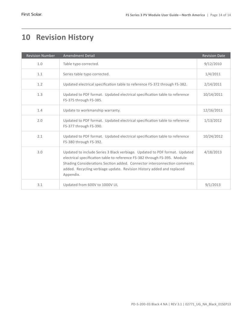
10 Revision History
RevisionNumber Amendment Detail Revision Date
1.0 Tabletypocorrected. 9/12/2010
1.1 Seriestabletypocorrected. 1/4/2011
1.2 UpdatedelectricalspecificationtabletoreferenceFS-372throughFS-382. 2/14/2011
1.3 UpdatedtoPDFformat.UpdatedelectricalspecificationtabletoreferenceFS-375 through FS-385.
10/14/2011
1.4 Updatetoworkmanshipwarranty. 12/16/2011
2.0 UpdatedtoPDFformat.UpdatedelectricalspecificationtabletoreferenceFS-377 through FS-390.
1/13/2012
2.1 UpdatedtoPDFformat.UpdatedelectricalspecificationtabletoreferenceFS-380 through FS-392.
10/24/2012
3.0 UpdatedtoincludeSeries3Blackverbiage.UpdatedtoPDFformat.UpdatedelectricalspecificationtabletoreferenceFS-382throughFS-395.ModuleShadingConsiderationsSectionadded.Connectorinterconnectioncommentsadded.Recyclingverbiageupdate.RevisionHistoryaddedandreplacedAppendix.
4/18/2013
3.1 Updated from 600V to 1000V UL 9/1/2013