Embed Size (px)
Citation preview

User Guide: Wireless Switch System © 2016 Harwil Corporation 16-01-18 Pic Page 1
User Guide
Wireless Switch System
HARWIL CORPORATION, 541 Kinetic Drive, Oxnard, CA 93030

User Guide: Wireless Switch System © 2016 Harwil Corporation 16-01-18 Pic Page 2
Section1 Before You Install and Use Your Equipment
1.1 Symbols & Safety Information
Listed below are the International Symbols used on the product, or in this manual.
Danger: Electric Shock Hazard
Warning: Refer To Documentation and User Guide
General Safety Guidelines
Follow all safety guidelines outlined in this guide and/or marked on the unit.
Never install or operate this product outside the specifications listed in this guide.
Never install and operate in flammable or explosive environments.
Install your unit in a location that is out of the reach of unauthorized personnel.
Always install additional disconnect and safety devices to provided added protection.
Never operate this product outside the environmental limits specified in this guide.
Electrical Safety Guidelines
Never attempt maintenance or service while power is connected.
Installation and all wiring should be done by a trained professional.
Note: Personnel entrusted with installation, setup and operation of this product must be suitably
qualified and trained. The required knowledge and experience can be gained via training courses
and appropriate on-the-job instruction. Personnel should have this user guide available to them at all
times when working with this product.
RF Safety Guidelines
Only operate this product with the antenna provided or listed in this guide.
Never operate this product where there will be people closer than 20 cm during normal use.
Never operate multiple switch transmitters within 20 cm or less from each other.
Never operate other RF transmitters within 20 cm or less of this product.

User Guide: Wireless Switch System © 2016 Harwil Corporation 16-01-18 Pic Page 3
1.2 Condition of Use
Your wireless switch system is not designed, intended or authorized for use in medical applications,
applications intended to sustain or support life, in any nuclear facilities or any other application
where the failure of the product could create a situation where catastrophic property damage,
personal injury or death may occur. In the event that the Customer purchases or uses this product for
any such unintended or unauthorized application, the Customer shall indemnify and hold harmless
Harwil Corporation and its officers, directors, employees, agents, affiliates, successors and assigns
against all claims, costs, damages and expenses (including reasonable attorneys' and expert witness'
fees) arising out of or in connection with, directly or indirectly, any claim for property damage,
personal injury or death associated with such unintended or unauthorized use, even if such claim
alleges that Harwil Corporation and its affiliates was negligent regarding the design or manufacture
of the subject product.
1.3 Unpacking
Unpack your product carefully and inspect for any shipping damage. Notify the carrier immediately if
you find damage.
The following items are included with your system:
Two Antennas
Switch Transmitter and Relay Receiver Units (Optional Battery Holder in Switch Unit.
This User Guide
Section 2 Introduction
2.1 Product Description
The Harwil Wireless Switch Transmitter/Receiver Set provides medium range, point-to-point, license-
free I/O communications to remote, or difficult to reach locations up to 1 mile in distance LOS (Line-
of-site) between the switch transmitter and relay receiver unit. The switch board is activated by any
dry-contact input. The receiver features dual control relays that can be configured for independent
operation or one relay can be latched for Pump Up/Pump Down operation.

User Guide: Wireless Switch System © 2016 Harwil Corporation 16-01-18 Pic Page 4
2.2 Switch Transmitter/ Relay Receiver Boards
Switch Transmitter Board – See Photo back of Catalog for correct Switch Positions
Figure 1. Switch Transmitter Board
1). RF Module – The RF Module facilitates communication between the transmitter and receiver boards.
2). Dip Switch 1 – Normal Position OFF – Controls sleep function of board (Set ON for Set Up Testing)
Dip Switch 2 – Normal Position ON – Status Light #3 (Set OFF to extend Battery Life)
Normal Positions are the LED ON Diagram above
3). RF Status LED – The “Status” LEDs blinks on/off during switching function to indicate the unit is active.
4). Switch #1 (SW1) Input – Connection for Switch #1. This input controls Relay #1 on the receiver board.
5). Switch #2 (SW2) Input - Connection for Switch #2. This input controls Relay #2 on the receiver board.
6). DC Power Connection – Connection to power unit with a hard-wired DC supply.
7). Battery Connection – Connection to power the unit by battery.

User Guide: Wireless Switch System © 2016 Harwil Corporation 16-01-18 Pic Page 5
Relay Receiver Board
Figure 2. Relay Receiver Board
1). RF Module – The RF Module facilitates communication between the transmitter and receiver boards.
2). Latch Function Select – Switch is used to select non-latching function “A”, or latching function “B”.
A: Normal Switch Functions = Latching OFF Dip Switch :1 ON – Dip Switch 2: OFF
B: Latching Switch Relay – Pump-Up or Pump Down using 2 level Switches
Latching ON = Dip Switch :1 OFF – Dip Switch 2: ON
2). Latch Function Select – Switch is used to select Latching, or non-latching function.
3). RF Status LED – The “Status” LEDs blinks on/off during switching function to indicate the unit is active.
4). Low Power LED – This LED will begin to illuminate as the battery voltage for the switch board gets low.
5). RF Signal Strength LEDs – These LEDs act as a signal strength meter that aids in system installation.
6). Relay #2 – Location of Relay #2
7). Relay #1 – Location of Relay #1
8). Relay #1 – Terminal block connection for Relay #1
9). Relay #2 – Terminal block connection for Relay #2
10). DC Power Input – Terminal block connection for DC power input.
11). AC Power Input – Terminal block connection for AC power input.
IMPORTANT: Jumper Wires in JP2&JP3 = 120VAC or Jumper Wires in JP1 only = 220VAC

User Guide: Wireless Switch System © 2016 Harwil Corporation 16-01-18 Pic Page 6
Section 3 Specifications
3.1 Specifications
GENERAL SPECIFICATIONS
Radio Frequency: 2.4 GHz, License Free, Spread Spectrum
RF Protocol: 802.15.4
Transmit/Receive Distance: Up to 1 Mile Line-of-sight (300’ Indoor/Urban)
Antennas: 7dbi Omni Directional (Supplied with units)
RF Input/output Impedance: 50 Ohms
Operating Temperature: -10 to 130 ºF (-23 to 54 ºC)
Transmitter/Receiver Code Matching: Factory Set
Wire Connections: Terminal Block, 12-18 AWG
SWITCH TRANSMITTER SPECIFICATIONS
Input Signal: Dry-contact Switch (2 Ea.)
RF Power Output: 63mW
RF Data Rate: 250 Kbps
OPERATING POWER
Hard Wired DC Supply: 9-24Vdc @ 300mA
Battery Power: See table in Section ??
RELAY RECEIVER SPECIFICATIONS
RF Receive Sensitivity: -100 dBm
OPERATING POWER
Hard Wired DC Supply: 15-24Vdc @ 750mA
Hard Wired AC Supply: 120 or 240VAC 50/60Hz @ 12 Watts (Factory Set)
CONTROL RELAYS
Relay 1: SPDT, 15A 120/240VAC
Relay 1 Function: Latching/Non-latching (User Selectable, See section ??)
Relay 2: SPDT, 10A 120/240VAC
Relay 2 Function: Non-latching
Note: Relay #2 is not available for use when Relay #1 is set for latching operation.

User Guide: Wireless Switch System © 2016 Harwil Corporation 16-01-18 Pic Page 7
3.2 Environmental Operating Conditions
This product has been designed to provide performance and durability over its life time. To keep this
product working correctly it should be handled with care and only operated within the following
recommended environmental operating conditions.
A ambient operating temperature range of -10 to130 ºF (-23 to 54 ºC)
A relative humidity of 0-90% Non-condensing
3.3 Regulatory Approvals, Location Use & Export Compliance
REGULATORY APPROVALS
Regulatory: FCC Part 15 (No license required)
FCC (USA): OUR-XBEEPRO
IC (Canada): 4214A-XBEEPRO
The enclosed device complies with Part 15 of the FCC Rules. Operation is subject to the following two
conditions: (i.) this device may not cause harmful interference and (ii.) this device must accept any
interference received, including interference that may cause undesired operation.
Statement of CE Conformity
Harwil Corporation is committed to compliance with the laws and regulations in each country into
which we ship our products. Please contact us to learn the current status of CE compliance for this
product.
Location Use
Standard models of this product are limited to the sale and use in North America only. Additional
models are available for use in Europe (EU), Australia, New Zealand and Japan. Please contact us for
model number and availability.
Export Compliance Policy
Customer shall not, directly or indirectly, export, re-export, transfer, furnish or ship products in violation
of any applicable export control laws or regulations of any country having jurisdiction over the
products, including any and all US law or US Government export controls. Customer agrees, at
Customer’s own expense, to comply with all applicable export laws and will, in accordance with the
indemnification provisions of these Terms and Conditions, indemnify, defend and hold Harwil
Corporation harmless from any claim against Harwil Corporation due to Customer’s violation or
alleged violation of any export laws.

User Guide: Wireless Switch System © 2016 Harwil Corporation 16-01-18 Pic Page 8
Section 4 Installation
4.1 General Guidance
Your Wireless Switch System must be installed and maintained as described in this guide to ensure
reliable safe operation. Confirm the voltage and current draw of your connected load to the relay
board is consistent with the design specifications of this product and your application will not exceed
the maximum load capacity listed.
4.2 Mounting and Area Environment
This product has been designed for indoor or outdoor use. Insure that the unit has sufficient area for
proper antenna positioning. See below.
************************* CAUTION *******************************
Never operate this product in areas where flammable liquids, gases or any other flammable
materials are, or might be present.
4.3 Antenna Installation & Positioning
Proper antenna installation and positioning is important and will allow you to achieve maximum
performance and distance between your switch transmitter and relay receiver unit. This will reduce
the possibility of a lost connection during operation.
Antenna Basics
When installing your switch transmitter and relay receiver it is important to install both units in such a
way as to optimize the position of both antennas within what’s known as the “Fresnel Zone”. A Fresnel
Zone can be thought of as a football shaped invisible tunnel between two antennas that provides an
optimum path for the RF signals between your switch transmitter and relay receiver.
Figure 3. The “Fresnel Zone”

User Guide: Wireless Switch System © 2016 Harwil Corporation 16-01-18 Pic Page 9
In order to achieve maximum distance, the path in which the RF signals travel must be free of all
obstructions. Obstacles in the path will decrease the transmit/receive distance. Also, if the antennas
are mounted too low to the ground, most of the Fresnel zone ends up being obstructed by the earth
resulting in significant reduction in transmit/receive distance. Your antennas should be mounted as
high off of the ground as possible.
NOTE:
It is important to understand that your application environment may change over time due to new
equipment, buildings or other RF equipment being installed. There can also be change within your
building such as new construction, etc. If new obstacles are added between your switch transmitter
and relay receiver you may need to move and reposition your antennas.
Connecting Your Antennas
Your Switch Transmitter/Relay Receiver has been shipped to you with standard antennas already
included. In some difficult installations you may wish to place a remote antenna farther away to
maximize transmission range to the relay receiver. A remote antenna kit option can be ordered that
include an antenna extension cable and antenna mounting bracket. Please note that very long
antenna extension cables will always add loss to the signal strength. The longer the cable the more
signal will be lost over the cable. Because of this the length of the cable should be kept as short as
possible. Use of any other antenna then what’s supplied with your system or what’s available as an
option may void FCC and IC regulatory compliance.
Horizontal Antenna Placement
If the antenna for you switch transmitter is mounted in a horizontal position you should mount your
relay receiver antenna in the same polarization.
Figure 4: Horizontal Antenna Example

User Guide: Wireless Switch System © 2016 Harwil Corporation 16-01-18 Pic Page 10
Vertical Antenna Placement
If your switch transmitter is mounted in a vertical position in your application you should mount your
relay receiver antenna so that the same polarization.
Figure 5. Vertical Antenna Example
4.4 RF Signal Strength LEDS
The switch transmitter board has three green LEDs near the bottom right side. These LEDs act as an RF
signal strength to aid during the installation process. The LEDs will illuminate as the RF signal between
the switch transmitter and relay receiver gets stronger.
(1) LED Illuminated – Good signal strength
(2) LEDs Illuminated – Very good signal strength
(3) LEDs illuminated – Maximum signal strength
Note: Signal strength LEDs provide aid during installation and positioning of your antennas. The LEDs
only illuminate always during normal operation. Each time a switching function occurs the LEDs will
illuminate and update their status. During sleep periods in between switching the LEDs will not be
illuminated.
Section 5 Powering Your Boards
5.1 Powering Your Boards
WARNING: Electrical Shock Hazard
All wiring should be done by a qualified suitably trained person.
CAUTION: Insure all control output connections are well insulated.
CAUTION: Additional fusing is recommended in series with relay board control
connections.

User Guide: Wireless Switch System © 2016 Harwil Corporation 16-01-18 Pic Page 11
5.2 Powering the Switch Transmitter Board
The Switch Transmitter Board has two different power connections. One that you can power with a
standard battery marked TB4, and one marked TB3 that you can hard-wire with a DC power supply.
Descriptions, figures and tables that follow provide guidance on what different power sources you
can use and how to connect them.
Battery Power Only Operation
The switch transmitter board can be by a primary cell battery alone. There are two different ways you
can connect and use a battery. Terminal block TB4 is for battery power from 2.7 - 4.5V DC, You can
also connect a 12 – 24V DC battery to the TB3 Terminal block. See diagrams below.
Connection for Battery Power Only Operation
Figure 6. For Battery Power of 2.7-4.5 Volts DC
CAUTION: NEVER CONNECT A VOLTAGE GREATER THAN 4.5V TO THE TB4 TERMINAL BLOCK OR YOU WILL
DAMAGE YOUR UNIT.
User Guide: Wireless Switch System © 2016 Harwil Corporation 16-01-18 Pic Page 12
Figure 7. For Battery Power of 12-24 Volts DC
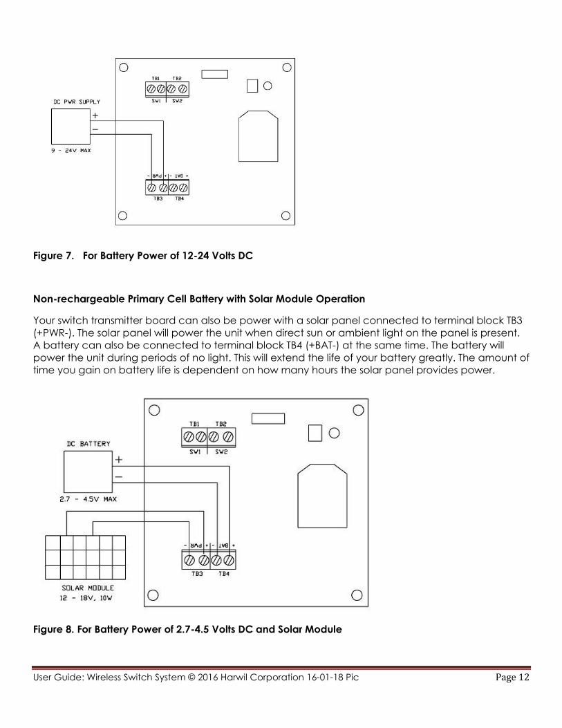
Non-rechargeable Primary Cell Battery with Solar Module Operation
Your switch transmitter board can also be power with a solar panel connected to terminal block TB3
(+PWR-). The solar panel will power the unit when direct sun or ambient light on the panel is present.
A battery can also be connected to terminal block TB4 (+BAT-) at the same time. The battery will
power the unit during periods of no light. This will extend the life of your battery greatly. The amount of
time you gain on battery life is dependent on how many hours the solar panel provides power.
Figure 8. For Battery Power of 2.7-4.5 Volts DC and Solar Module

User Guide: Wireless Switch System © 2016 Harwil Corporation 16-01-18 Pic Page 13
Rechargeable Battery with Solar Module Operation
Your switch transmitter board can also be powered with a 12V rechargeable battery, solar panel
and solar charge controller. The battery is connected to terminal block TB3 (+PWR-). The solar panel
and solar charge the control will re-charge the battery each day. This setup will provide
uninterrupted power to your switch transmitter for many years.
Figure 9. For 12V Rechargeable Battery and Solar Module
Battery Power Estimated Life (Battery Only)
The tables below provide an estimated life of your battery(s) during normal, ideal conditions. The
values provided are an estimate.
NOTE: Quality of the batteries, ambient temperature cycling and the number of switch operations
can effect these estimates greatly.
Battery(s) Connected to the +BAT– (TB4) input
Battery Example Battery 1-2 Switch
Changes/day
3-4 Switch
Changes/day
2 Ea. AA, Lithium, 1.5V Energizer L91 210 Days 135 Days
3 Ea. C, Alkaline, 1.5V Energizer Industrial EN93 375 Days 179 Days
1 Ea. C, Lithium, 3.6V XENO XL-145F 275 Days 155 Days
3 Ea. D, Alkaline, 1.5V Energizer Industrial EN95 510 Days 282 Days

User Guide: Wireless Switch System © 2016 Harwil Corporation 16-01-18 Pic Page 14
Battery Power Estimated Life (Battery used in conjunction with Solar Module (SM) option)
These tables provides the estimated life of your battery(s) during normal operation with the optional
Solar Module (SM) installed. The values provided are an estimate. Quality of the batteries, ambient
temperature cycling and the number of switch operations can effect these estimates.
Battery(s) Connected to the +BAT– (TB4) input and a Solar Module Connected to +PWR- (TB3) Input
Battery Example Battery 1-2 Switch
Changes/day
3-4 Switch
Changes/day
2 Ea. AA, Lithium, 1.5V w/SM Energizer L91 245 Days 161 Days
3 Ea. C, Alkaline, 1.5V w/SM Energizer Industrial EN93 425 Days 209 Days
1 Ea. C, Lithium, 3.6V w/SM XENO XL-145F 331 Days 186 Days
3 Ea. D, Alkaline, 1.5V w/SM Energizer Industrial EN95 585 Days 330 Days
Estimated Values are based on the Solar Module option (SM) receiving direct light a minimum of 4-5 hours/day.
************************** CAUTION ******************************
CONNECTING A POWER SOURCE ABOVE 4.2VDC TO THE +BAT– (TB1) INPUT OF YOUR SWITCH
TRANSMITTER BOARD WILL CAUSE DAMMAGE TO THE UNIT.
Using a 12V Battery Connected to the +PWR– (TB3) input
Battery Recommended Product 1-2 Switch
Changes/day
3-4 Switch
Changes/day
12V, 18Ah Battery Universal Battery – UB12180 250 Days 225 Days
12V, 26Ah Battery Universal Battery – UB12260 355 Days 315 Days
************************** CAUTION ******************************
NEVER CONNECT BOTH A BATTERY AND A HARD-WIRED POWER SUPPLY TO THE +PWR- (TB3) INPUT AT THE
SAME TIME. THIS WILL OVER CHARGE THE BATTERY AND CAUSE A SAFTEY HAZARD.
Powering the Switch Board with a Hard-wired DC Supply
The switch board can be powered by a hard-wired dc supply. When a hard-wired supply is used a
battery is not needed unless you want to have a battery backup in the event of power loss.
5.2 Powering the Relay Receiver Board
The Relay receiver board can be power by either AC or DC voltage. Never connect both AC and
DC power at the same time to power the board. There are two different models for AC voltage. The
unit must be factory configured for 120VAC or 240VAC. Any model of the Relay board can also be
powered by 15-24V DC.
NOTE: EVEN IF YOU POWER THE RELAY BOARD WITH DC POWER YOU CAN STILL CONNECT AC
VOLATAGE 120/240VAC TO THE RELAY CONTACTS TO CONTROL YOUR AC POWERED EQUIPMENT.
User Guide: Wireless Switch System © 2016 Harwil Corporation 16-01-18 Pic Page 15
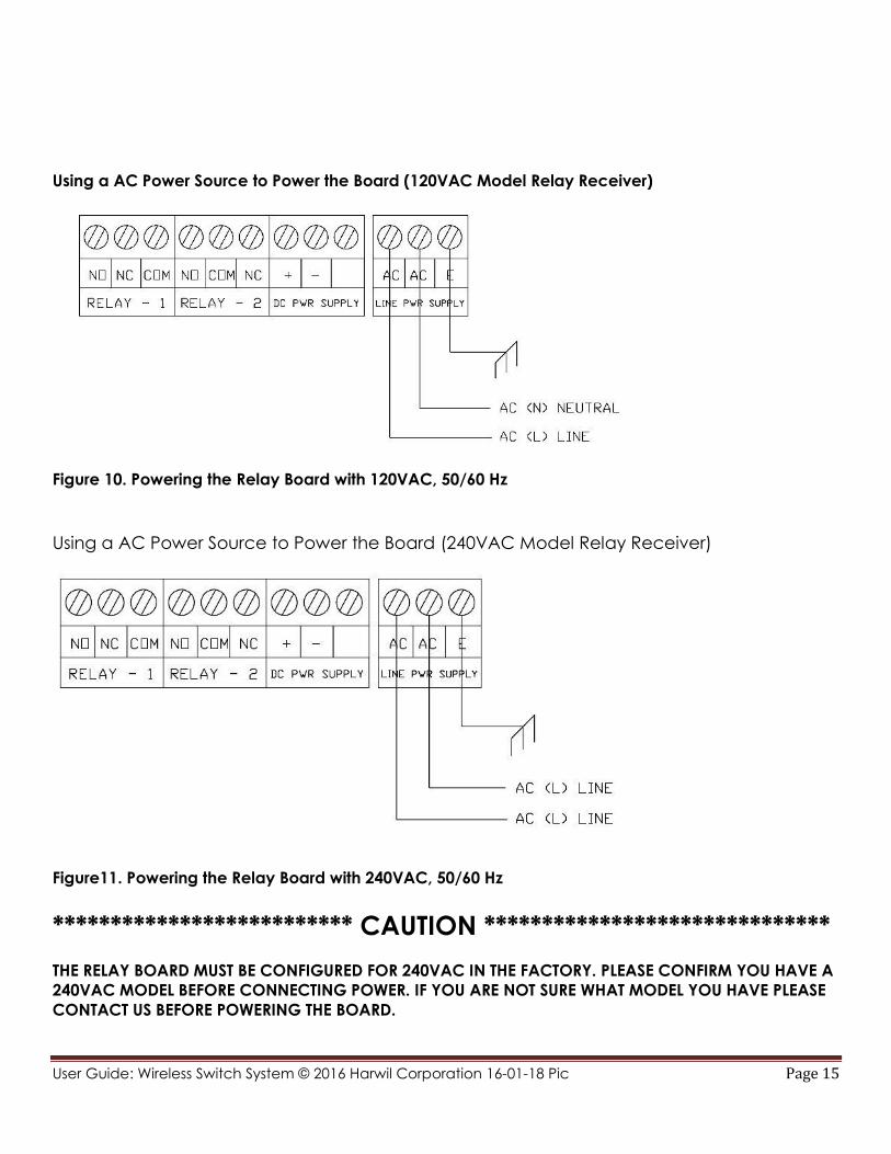
Using a AC Power Source to Power the Board (120VAC Model Relay Receiver)
Figure 10. Powering the Relay Board with 120VAC, 50/60 Hz
Using a AC Power Source to Power the Board (240VAC Model Relay Receiver)
Figure11. Powering the Relay Board with 240VAC, 50/60 Hz
************************** CAUTION ******************************
THE RELAY BOARD MUST BE CONFIGURED FOR 240VAC IN THE FACTORY. PLEASE CONFIRM YOU HAVE A
240VAC MODEL BEFORE CONNECTING POWER. IF YOU ARE NOT SURE WHAT MODEL YOU HAVE PLEASE
CONTACT US BEFORE POWERING THE BOARD.

User Guide: Wireless Switch System © 2016 Harwil Corporation 16-01-18 Pic Page 16
Using a DC Power Source to Power the Relay Board
Figure 12. Powering the Relay Board with 15 - 24V DC Power Supply
Section 6 Switch Transmitter Operation
6.1 Connecting switches to your transmitter
The inputs connected to the transmitter must be “dry-contact type. That means you do not need to
supply any power on the input. The input is a two wire connection that can be a simple mechanical
manual operated switch, a level or flow switch, or the contacts of a relay.
Figure 13. Switch Board - Switch Input Connection

User Guide: Wireless Switch System © 2016 Harwil Corporation 16-01-18 Pic Page 17
Section 7 Relay Receiver Operation
7.1 Connecting Your Equipment to the Relays
Each of the two relays on the board provide one set of SPDT contacts. The relays are marked with
“NO” for normally open, “NC” for normally closed, and “C” for the contact that’s common to both.
The capacity of each relays is listed on the specification page in this guide.
Figure 14. Relay Board - Relay Connections
7.2 Latching Function for Relay #1
Relay #1 can be latched to provide Pump up/ Pump down operation when two switches are used
on the switch transmitter board. See figure 1. For setting the latch function.
NOTE: WHEN THE BOARD IS CONFIFURED FOR LATCHING OPERATION RELAY #2 IS NOT AVAILABLE FOR
USE AND YOU SHOULD NEVER CONNECT WIRES TO THE CONTACTS FOR RELAY #2.

User Guide: Wireless Switch System © 2016 Harwil Corporation 16-01-18 Pic Page 18
Switch Board Photo (Normal Switch Positions)

User Guide: Wireless Switch System © 2016 Harwil Corporation 16-01-18 Pic Page 19
Relay Board Photo (Normal Switch Positions - Not Latching)


![SAP HowTo Guide - Unlocking User SAPStar [User Guide]](https://img.pdfslide.net/doc/110x75/544ac849b1af9f7c4f8b4bd1/sap-howto-guide-unlocking-user-sapstar-user-guide.jpg)


![User Guide...User. {{]}]} {}]}](https://img.pdfslide.net/doc/110x75/60918ca14327954d24291644/-user-guide-user-.jpg)