Embed Size (px)
Citation preview

User Guide
Datgel
Survey Tools gINT Add-In
DSVT-UG-001 - 1.04
March 2010

Disclaimer The information in this publication is subject to change without notice and does not represent a commitment on the part of Datgel Pty Ltd. The software described in this document is furnished under a license agreement or nondisclosure agreement. The software must be used or copied only in accordance with the terms of the agreement.
Every effort was made to ensure accuracy of this information. However, Datgel Pty Ltd makes no warranty as to the correctness of this information or the supplied files.
Printed in Australia. All rights reserved worldwide. No part of this publication may be reproduced in any form or by any means without the prior written consent of Datgel Pty Ltd. Comments are welcome and become the property of Datgel Pty Ltd.
All products mentioned are trademarks of the respective producers.
Copyright © Datgel Pty Ltd 2005-2010
Datgel Pty Ltd Suite 8, Level 1, The Hub 89 - 97 Jones Street Ultimo NSW 2007 Australia
Tel: +61 2 8202 8600 Fax: +61 2 8202 8606
Email: [email protected] Website: www.datgel.com

Survey Tools gINT Add-In Datgel User Guide i DSVT-UG-001 - 1.04- March 2010
Contents About the Product ................................................................................................................ ii
Support .............................................................................................................................................. ii System Requirements ....................................................................................................................... ii
gINT .............................................................................................................................................................. ii Hardware and Operating System .................................................................................................................. ii Required Windows Components ................................................................................................................... ii
Conventions and typography used in this guide ............................................................................... ii Field Colours ..................................................................................................................................... iii
1 Installation and Licensing ............................................................................................ 1 1.1 Installation Overview ............................................................................................................... 1 1.2 Package Contents .................................................................................................................. 1 1.3 Before Installation ................................................................................................................... 1 1.4 Install DLL Programs .............................................................................................................. 1 1.5 Merge gINT Library Objects ................................................................................................... 4 1.6 Merge gINT Project File Tables and Fields ............................................................................ 7 1.7 Validate License ..................................................................................................................... 9
2 Grid File Pre-processing Tool.................................................................................... 10 2.1 Usage .................................................................................................................................... 11
3 Set Elevation or Depth from Surface Tool ................................................................. 13 3.1 Usage .................................................................................................................................... 14 3.2 Setting Storage ..................................................................................................................... 14
4 Set Seabed Elevation Tool ........................................................................................ 16 4.1 Tables ................................................................................................................................... 16
4.1.1 Tide Table .................................................................................................................................. 16 4.1.2 Point Table ................................................................................................................................. 16
4.2 Usage .................................................................................................................................... 17 5 Set Coordinate Chainage Offset Tool ....................................................................... 18
5.1 Usage .................................................................................................................................... 19
Tables
Table 1 – Field Colours .............................................................................................................................. iii

Survey Tools gINT Add-In Datgel User Guide ii DSVT-UG-001 - 1.04- March 2010
About the Product The Datgel Survey Tools consist of a range of utilities for the processing and querying of 3D surfaces, alignments and tidal data. The four tools are:
Grid File Pre-processing Tool: Pre-processes surface files to produce perfect grids, slice up over sized grids, invert elevations and replace null values. .
Set Elevation or Depth from Surface Tool: Sets the depth or elevation for a range of table structures from 3D surfaces.
Set Seabed Elevation Tool: Calculates seabed elevation for each point based on water depth and tidal information.
Set Coordinate Chainage Offset Tool: Calculates the coordinates to/from chainage and offset based on alignment data.
You need to complete the installation procedure (see 1 Installation and Licensing on page 1) and activate (see Datgel Product Licensing System User Guide) before you can use the Survey Tools.
Support
12 months support and maintenance is included with the license purchase. For technical support please email [email protected] or call +61 2 8202 8600.
System Requirements
gINT
The product runs optimally using gINT 8.2.003 or higher, however it will run using gINT 8.1 or higher.
The product will run using gINT Logs, gINT Logs Plus, and gINT Professional.
Hardware and Operating System
Same system requirements as gINT 8.2, see: http://www.gintsoftware.com/products_requirements.html.
Required Windows Components
1. Windows Installer 3.1
2. .NET 3.5 Framework SP1
Conventions and typography used in this guide
Note: Tips and additional Information to help you.
> Used to indicate a series of menu commands.
e.g. Select File > Open.
| Used to indicate a gINT Application Group, Application, Table Group or Table , e.g. DATA DESIGN | Project Database
Bold Text Items you must select, command buttons, or items in a list.
e.g. Navigate to UTILITIES | Convert Projects (4th
tab).
Italics Emphasis Use to emphasize the importance of a point such as parameters.
e.g. Data Entry – Check Omit Must Save prompt when save is required

Survey Tools gINT Add-In Datgel User Guide iii DSVT-UG-001 - 1.04- March 2010
CAPITALS Names of keys on the keyboard. for example, SHIFT, CTRL, or ALT.
KEY+KEY Key combinations, for example CTRL+P, or ALT+F4.
Code Snippet Indicates a code snippet within a paragraph
Code sample Indicates a sample program codes inserted in user guide e.g.
public override string ToString ()
File name or path Used for formatting file name and paths e.g. di_lib.glb or
V:\10 gINT\Datgel Install Files\
Table_Name Database table name, e.g. POINT_TABLE.
Field_Name Database field name; e.g. PointID
Command line Command line, presented exactly as it must be entered e.g.
cdir
Field Colours
Each of the fields in the project tables have been coloured to improve the data entry process as indicated below in Table 1.
Table 1 – Field Colours
Field Colour Field Name and Explanation
Yellow gINT Key Field – mandatory data entry
Pastel Purple AGS Data – data associated with the AGS Data Interchange Format
Pastel Green Calculated Field – data is written to this field by Datgel’s code
Pastel Beige Data Entry Field – data should be entered into this field, or data in this field influences the calculation
Pastel Red Legacy Data Field – historic data entered here, is typically from an old database
Pastel Blue Output Option – used to control how data displays on a report
Pastel Orange Remark or Metadata Field – additional data associated with the primary information
Grey Read-only


Survey Tools gINT Add-In – Datgel User Guide 1 DSVT-UG-001 - 1.04- March 2010
1 Installation and Licensing
1.1 Installation Overview
There are four parts to the installation process:
Install DLL program;
Merge gINT library objects;
Merge gINT project table and fields to your project file and your data template;
Activate the product license.
The first three steps can be performed in any order and are described below. The license validation procedure must be done last and is described in the Datgel Product Licensing System User Guide.
1.2 Package Contents
Your software purchase may have come with the following contents:
Applications CD which normally has the following folders:
\Example Data Files \gINT Files
\Documentation
\Installation files
A hardware license key
1.3 Before Installation
A few basic preparations can help ensure an effortless installation.
Make sure that the computer where you plan to install the program meets the minimum hardware and software requirements.
Connect your PC to Internet before installation (must have a working Internet connection).
The Survey Tool requires that the Microsoft .net 3.5 framework is installed on the PC prior to the installation of the Tool. If your PC does not have the .net 3.5 framework installed, then it will be automatically downloaded and installed during the Tool installation process.
Log into the PC with Administrator privileges before starting installation.
It is recommended that you exit out of other applications that are running on your PC.
Close gINT before you start the installation.
Keep the serial number and license number handy.
1.4 Install DLL Programs
1. If you received an installation CD, then insert the CD and browse to the folder
\Installation Files
2. Double click the file named Setup.exe
3. Click Run to begin installation.
Follow the on screen instructions when installation begins.
4. Click Next on the Welcome to the Datgel Survey Tool Setup dialog.

Survey Tools gINT Add-In – Datgel User Guide 2 DSVT-UG-001 - 1.04- March 2010
5. Scroll and carefully read the License Agreement, and choose option I Agree, and click Next.
Alternatively choose I Do Not Agree and click Cancel if you disagree with the license agreement. The installation will stop and exit.
6. On the Select Installation Folder dialog, either accept the default folder (recommended) or select Browse to specify the folder where you want to install the Survey Tools Add-In.
Leave Everyone bulleted to indicate that anyone logged onto the PC can use the Survey Tool Add-In.
Click Next when ready.

Survey Tools gINT Add-In – Datgel User Guide 3 DSVT-UG-001 - 1.04- March 2010
OPTIONAL Click on Disk Cost to view the disk space statistics. Click OK when done.
7. Click Next to start installation.
8. Observe the progress bar to monitor installation progress.

Survey Tools gINT Add-In – Datgel User Guide 4 DSVT-UG-001 - 1.04- March 2010
9. Click Close when the Installation Complete dialog is displayed.
1.5 Merge gINT Library Objects
Note: If Steps Error! Reference source not found. to Error! Reference source not found. have been done by Datgel’s developers or done previously by you or a colleague, or you just wish to use the example files provided by Datgel, then proceed to Section Error! Reference source not found. Error! Reference source not found..
Proceed with the following steps to merge the gINT Library components into your Library file.
1. Make a backup copy of your existing library file. By default this is located at:
C:\Program Files\gINT\libraries\
2. Start gINT and open the library and project file you wish to use with Datgel Survey Tool gINT
Add-In.
The opened project and library files are displayed at the top of the gINT Window.

Survey Tools gINT Add-In – Datgel User Guide 5 DSVT-UG-001 - 1.04- March 2010
3. Select UTILITIES > Lib Merge/Copy.
4. Check the bullet that reads Merge from.
5. In the Source Library File pane, browse the installation CD for file
Datgel_Survey_Tools_lib_##.glb where ## is the version number.
6. Check the bullet that reads Select All.
7. Check the bullet that reads Query On Overwrite.
8. Click button to move all tables from the Available Source Tables pane on the left to the Tables to Merge/Copy pane on the right side.

Survey Tools gINT Add-In – Datgel User Guide 6 DSVT-UG-001 - 1.04- March 2010
9. Click Execute.
10. Click button to move the selected items (highlighted blue) from the Available Items pane to the Items to Process pane on the Add-Ins dialog.
11. Click OK to process selected items.
12. Repeat steps 10 and 11 for all other items.
Take care to read the overwrite dialog and click Yes if you wish to overwrite the file, ELSE click No.

Survey Tools gINT Add-In – Datgel User Guide 7 DSVT-UG-001 - 1.04- March 2010
This will merge in the Survey Tools Add-In menu item, gINT Rules modules, and library tables relevant for the use of the Survey Tools.
13. Click OK to finish the merge.
1.6 Merge gINT Project File Tables and Fields
1. Make a backup copy of your existing project file. By default this is located at:
C:\Program Files\gINT\projects\
2. Start gINT and open the library and project file you wish to use with Datgel Survey Tool.
3. Select DATA DESIGN | Project Database.
OPTIONAL If you get the message Use the File menu to select or create a database, then
select File > Open File > Open Project, browse to the location you have your project file
(.gpj) stored at, click on the project file name, and click Open.
4. Select File > Open File > Current Project… to open your current project file.
5. Select Tables > Import Multiple Tables... then browse the installation CD and select the file
Datge_Survey_Tools_##.gpj where ## is the version number.
6. Click Open.
7. Select the following tables to import, and click OK.
8. Select/check Additional Modules > Alignment Support
Note: If you have already checked Alignment Support ( ) under Additional Modules menu, then the gINT Alignment Coordinates and gINT Alignment tables will already exist
and will not show in the screen above.

Survey Tools gINT Add-In – Datgel User Guide 8 DSVT-UG-001 - 1.04- March 2010
9. Select the POINT table from the yellow drop down list.
10. Select Tables > Merge Fields from Other File... then browse the installation CD and select
the file D:\gINT Files\Datgel_Survey_Tools_##.gpj where ## is the version number
and assuming D: is your CD/DVD drive letter (replace with appropriate drive letter if not).
11. Click Open.
12. On the Available Tables dialog, select Point table, and click OK.
13. On the Fields to Merge dialog, select the 14 fields highlighted, and click OK to merge fields into the POINT table.

Survey Tools gINT Add-In – Datgel User Guide 9 DSVT-UG-001 - 1.04- March 2010
14. Click OK if you get the following dialog.
Note: The Tidal fields must exist with the said names for the code to work. The other fields are
optional or may have different names to those listed.
1.7 Validate License
After installation (and before using the Survey Tool Add-in), validate the user license as described in Chapter 3 of the Datgel Product Licensing System User Guide.
Note: You only need to activate this product when you run the Datgel Survey Tool in gINT 8 for the first time.

Survey Tools gINT Add-In – Datgel User Guide 10 DSVT-UG-001 - 1.04- March 2010
2 Grid File Pre-processing Tool The Grid File Pre-Processing Tool allows the user to:
Pre-process a grid surface file to fill in the null regions to form a perfect rectangular outline with no holes
Divide the source grid file into several smaller rectangular grid files to cope with larger surface files
Invert data, i.e. multiply Z by -1
To launch Grid File Pre-processing Tool gINT Add-In:
1. Be in gINT INPUT.
2. Select Add-Ins > Survey Tool > Surface File Pre Process.
On this screen:
Source file: The file path of the source XYZ grid file to be processed. Use the “Browse” button to browse to the file.
Target file: The file path where the output XYZ grid file(s) will be generated. Use “Browse” button to select browse to the file path.
File size: Displays the source file is in bytes and Megabytes.
Number of rows: Shows the number of rows in the source file.
Min (E, N, Z): Shows the minimum East, North and Elevation values from the source file.
Max (E, N, Z): This information shows the maximum East, North and Elevation values from the source file.
East spacing: This information shows the East spacing between each row record in the source file. Ensure the east value of the row records in the surface file are equally spaced before you start the grid file pre-processing process.

Survey Tools gINT Add-In – Datgel User Guide 11 DSVT-UG-001 - 1.04- March 2010
North spacing: This information shows the North spacing between each row in the source file. Please make sure the north value of the row records in the surface file are equally spaced before you start the grid file pre-processing process.
Statistics Button: Use this button to display source file statistics. This is not required but it is useful to know the file statistics in order to decide how the target files are divided. Note that the source file statistics will be calculated and be shown in the Statistics section at the end of the pre-processing process.
Invert elevation checkbox: Check the “Invert elevation” box to invert elevation in the target grid file, i.e. multiple the elevation by -1. This is required only if the elevation in the source gird file has the elevation inverted and this needs to be corrected before import into gINT.
Round E,N decimal places: Specify a value here to round all values to a number of decimal places. Rounding can correct inconsistent grid spacing if the difference is very small. Leave this blank if you wish to omit any rounding.
Null value to replace with 1E10: gINT recognised values greater than or equal to 1E10 to be Null values. If the source grid file uses a different value to represent a Null, then enter that value in the text box and the Tool will replace the value with 1E10.
Surface file grid dimensions (E x N): Enter the East Grid dimension and North Grid dimension to cut the grid files into equally spaced portions. You can use “File Size” information to determine the East and North Grid dimensions. For example, if the surface file grid dimension is 2 x 2, the source surface file will be cut into two rows and two columns, resulting into 4 files and will be named as <Target File Name>_GridX1_GridY1.xyz, <Target File Name>_GridX1_GridY2.xyz, <Target File Name>_GridX2_GridY1.xyz and <Target File Name>_GridX2_GridY2.xyz.
Start pre-processing at row: You can specify the starting row in the source file for the process. This is useful if the source surface file has header information. If the actual surface record starts at row 5 in the surface file, then enter “5” in this box.
Execute button: Pre-process the source grid file.
Delimiter: The character used to separate the X, Y and Z values. The most common types can be selected from the pick list provided, or type in the delimiter character in this field.
Grid Spacing: the spacing between one coordinate to an adjacent coordinate in the grid file. If the grid spacing is known, enter the values in both East and North fields, and the Tool will use these values when pre-processing. If one or both fields are left blank, then the Tool will automatically determine the grid spacing.
2.1 Usage
1. Select source grid file.
2. Select target grid file.
3. Click Statistics button to display source grid file statistics.
4. Check Invert Elevation option if the source xyz file has the elevation inverted. Otherwise uncheck it.
5. Enter a new null value to replace the default null value.
6. Enter surface file grid dimensions. You can determine the dimensions by looking at the size of the source file.
7. Enter the pre-process starting row in the source file. If there is no header information in the source file, then enter 1 as the starting row.
8. Select a delimiter from the pick list, or enter one in the field.

Survey Tools gINT Add-In – Datgel User Guide 12 DSVT-UG-001 - 1.04- March 2010
9. Enter the grid spacing for East and North, if known.
10. Click Execute button to pre-process the source file.
11. You can view the generated target files in the target file directory.

Survey Tools gINT Add-In – Datgel User Guide 13 DSVT-UG-001 - 1.04- March 2010
3 Set Elevation or Depth from Surface Tool
The Set Elevation or Depth from Surface Tool allows the user to set an elevation or depth field of a project table in gINT from values in a gINT surface based on the PointID's East and North.
Surfaces may be stored in the project file or externally in a gsf file.
To launch Set Elevation or Depth from Surface Tool:
1. Select the INPUT tab.
2. Select Add-Ins > Datgel Survey Tools > Set Elevation or Depth from Surface.
On this screen:
Surface ID column: Surface ID is used to uniquely identify each row. This field is coloured yellow, and similar to the yellow coloured fields in gINT, this field must have a value before executing or closing the form.
Surface Name column: The surface name used when inserting a new surface into a selected table with PointID and ItemKey as the keyset.
Surface File Name column: External or internal surface file name. You can enter the exact surface file name or use a wildcard in the surface file name. For example, if you have surface file named as S_01, S_02 and S_03, in this column you can enter “S*” to include all these surface files when defining the elevation.
Table column: A drop down list of all the PointID, PointID,Depth and PointID,ItemKey keyset tables in current gINT Project file. Certain columns are not applicable depending on the table selection. These fields will be automatically coloured grey and become un-editable when changing the table name column, or become available when an applicable table is selected.
Elevation Field column: A drop down list of all the fields from the selected table to select the field that you want to set the elevation to. This will update the elevation for all the holes on the point table that have East and North (Destination X and Y) data. If an Elevation field is specified, then the Depth field will be greyed out and become un-editable until the Elevation field value is cleared.

Survey Tools gINT Add-In – Datgel User Guide 14 DSVT-UG-001 - 1.04- March 2010
Depth Field column: Defines the field on the selected table where the Depth values will the written. The column has a drop down list of all the fields from the selected table. The depth is relative to the elevation of the PointID, and is calculated by subtracting the elevation of the surface file from the elevation of the PointID, which is defined on the POINT table. This will update the depth for all the PointIDs that have East and North (Destination X and Y) data. If a Depth Field is specified, then the Elevation Field will be greyed out and become un-editable until the Depth field value is cleared.
Override Field column: Defines the Boolean field on the selected table that defines if the depth or elevation has been defined manually, and hence not to be overridden by this command. A drop down list of all the fields from the selected table. Ensure the selected override elevation field is a Boolean / check box field. This field is optional.
Set column: Indicates whether to set the elevation or not. If “Set” is checked, depth or elevation will be updated after Execute button clicked.
Execute Button: Sets the surface elevation.
3.1 Usage
1. Enter values into Surface ID, Surface Name, Surface File Name, Table Name, Elevation Name or Depth Name, Override Field, and Set columns.
2. Click Execute button to start the process. An error log will be shown in a message window at the end of the process.
The log file display a message for each PointID. For example, if the East and North lay outside the surface areas, then an error message will be listed.
3. Click Save and Close on the main form to return to gINT INPUT.
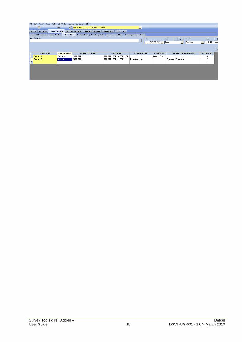
3.2 Setting Storage
The Set Surface Elevation Form is populated with data in DG_SURVEY_SET_ELEVATION_CONFIG table in the current gINT library file.
Survey Tools gINT Add-In – Datgel User Guide 15 DSVT-UG-001 - 1.04- March 2010

Survey Tools gINT Add-In – Datgel User Guide 16 DSVT-UG-001 - 1.04- March 2010
4 Set Seabed Elevation Tool Set Seabed Elevation Tool allows the user to calculate seabed elevation for each PointID based on water depth and tidal information. This will update all records on the POINT table that have tidal date/time and tidal water depth information.
To start Set Seabed Elevation Tool:
1. Select INPUT tab.
2. Select Add-Ins > Datgel Survey Tool > Set Seabed Elevation.
4.1 Tables
Explanations of the tables used in this gINT Add-In are listed below.
4.1.1 Tide Table
This table is stored in the project database. The keyset for this table is Date Time field. The Water Elevation field will be used when calculating the Elevation on the POINT table.
4.1.2 Point Table
The fields used in this Add-In are:
Tidal Water Depth: Stores each PointID’s Tidal Water Depth information.
Tidal Date Time: Stores each PointID’s Tidal Date Time information. This field is used by the Tool to get each PointID’s Tidal Water Elevation from the TIDE table.
Tidal Water Elevation: This field is used to store the tidal water elevation which is populated from TIDE table based on each PointID’s Tidal Date Time information.
Elevation: This field is used to store the calculated seabed elevation for each PointID.

Survey Tools gINT Add-In – Datgel User Guide 17 DSVT-UG-001 - 1.04- March 2010
4.2 Usage
The Elevation field on the POINT table is calculated using the add-in menu command Add-Ins > Datgel Survey Tool > Set Seabed Elevation. This will update all records on the POINT table that have Tidal Date Time, Tidal Water Depth information and corresponding Tidal data on the TIDE table. The user needs to manually enter each PointID’s Tidal Water Depth and Tidal Date Time information. Tidal Water Elevation field in POINT table will be updated from TIDE table based on each PointID’s Tidal Date Time information. Each PointID’s Elevation is calculated using the difference between each PointID’s Tidal Water Elevation and Tidal Water Depth values.
Survey Tools gINT Add-In – Datgel User Guide 18 DSVT-UG-001 - 1.04- March 2010
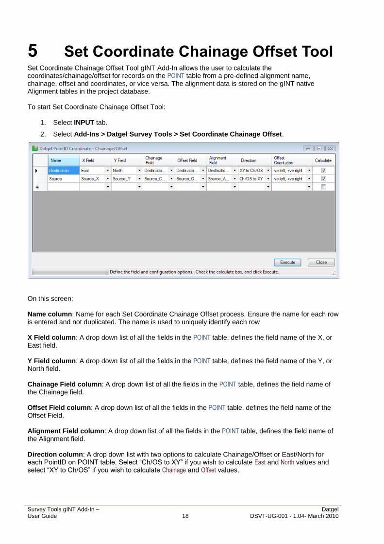
5 Set Coordinate Chainage Offset Tool Set Coordinate Chainage Offset Tool gINT Add-In allows the user to calculate the coordinates/chainage/offset for records on the POINT table from a pre-defined alignment name, chainage, offset and coordinates, or vice versa. The alignment data is stored on the gINT native Alignment tables in the project database.
To start Set Coordinate Chainage Offset Tool:
1. Select INPUT tab.
2. Select Add-Ins > Datgel Survey Tools > Set Coordinate Chainage Offset.
On this screen:
Name column: Name for each Set Coordinate Chainage Offset process. Ensure the name for each row is entered and not duplicated. The name is used to uniquely identify each row
X Field column: A drop down list of all the fields in the POINT table, defines the field name of the X, or East field.
Y Field column: A drop down list of all the fields in the POINT table, defines the field name of the Y, or North field.
Chainage Field column: A drop down list of all the fields in the POINT table, defines the field name of the Chainage field.
Offset Field column: A drop down list of all the fields in the POINT table, defines the field name of the Offset Field.
Alignment Field column: A drop down list of all the fields in the POINT table, defines the field name of the Alignment field.
Direction column: A drop down list with two options to calculate Chainage/Offset or East/North for each PointID on POINT table. Select “Ch/OS to XY” if you wish to calculate East and North values and select “XY to Ch/OS” if you wish to calculate Chainage and Offset values.
Survey Tools gINT Add-In – Datgel User Guide 19 DSVT-UG-001 - 1.04- March 2010
Offset Orientation column: A drop down list with two options to define offset orientation. Select “+ve left, -ve right” option if on the left of the chainage line is positive and select “-ve left, +ve right” option if on the left of the chainage line is negative.
Calculate column: This is used to indicate whether to calculate Coordinate Chainage Offset or not after “Calculate” button clicked.
Calculate Button: Start Set Coordinate Chainage Offset process for each PointID on the POINT table.
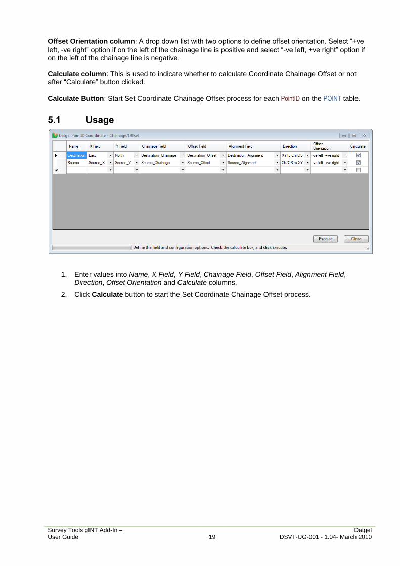
5.1 Usage
1. Enter values into Name, X Field, Y Field, Chainage Field, Offset Field, Alignment Field, Direction, Offset Orientation and Calculate columns.
2. Click Calculate button to start the Set Coordinate Chainage Offset process.