Embed Size (px)
Citation preview

Isothermal Technology Limited, Pine Grove, Southport, Merseyside, PR9 9AG, England Telephone: +44 (0)1704 543830 Fax: +44 (0)1704 544799 Email: [email protected] Website: www.isotech.co.uk
Pegasus 4000 Series 02-04/17
User Maintenance Manual
PEGASUS 4853 BASIC & SITE

2
Guarantee
ⓒIsothermal Technology Limited
This instrument has been manufactured to exacting standards and is guaranteed for twelve months against electrical break-down or mechanical failure caused through defective material or workmanship, provided the failure is not the result of misuse. In the event of failure covered by this guarantee, the instrument must be returned, carriage paid, to the supplier for examination and will be replaced or repaired at our option. FRAGILE CERAMIC AND/OR GLASS PARTS ARE NOT COVERED BY THIS GUARANTEE INTERFERENCE WITH OR FAILURE TO PROPERLY MAINTAIN THIS INSTRUMENT MAY INVALIDATE THIS GUARANTEE The company is always willing to give technical advice and assistance where appropriate. Equally, because of the programme of continual development and improvement we reserve the right to amend or alter characteristics and design without prior notice. This publication is for information only. This handbook contains information that has been reproduced with the kind permission of Eurotherm. Such data is subject to the following notice.
Isothermal Technology Limited Pine Grove, Southport, Merseyside, PR9 9AG, England
Telephone: +44 (0)1704 543830 / Fax: +44 (0)1704 544799 Email: [email protected] / Website: www.isotech.co.uk

3
Contents
1 UNPACKING AND INITIAL INSPECTION ......................................................................................... 5
2 BEFORE YOU USE THE EQUIPMENT ................................................................................................ 6
3 SUMMARY OF SYMBOLS .................................................................................................................... 7
4 ELECTRICITY SUPPLY ....................................................................................................................... 8
5 THE UNIT MUST BE EARTHED ................................................................................................. 9
6 EMC INFORMATION ................................................................................................................. 10
7 CAUTIONARY NOTE ................................................................................................................. 11
8 SAFETY WARNINGS ................................................................................................................ 12
8.1 ENVIRONMENTAL CONDITIONS ........................................................................................................................ 12 8.2 DO NOT MODIFY OR DISASSEMBLE ................................................................................................................. 12 8.3 BEWARE OF ELECTRICAL CONSIDERATIONS...................................................................................................... 12 8.4 BE CAREFUL WHERE IT IS USED ..................................................................................................................... 12 8.5 BE CAREFUL WITH EXTREMES OF TEMPERATURE .............................................................................................. 12 8.6 BE CAREFUL WITH INSERTS ........................................................................................................................... 12
9 CONSIDER THE ENVIRONMENT ..................................................................................................... 13
10 INTRODUCTION ............................................................................................................................. 14
10.1 COMPARISON CALIBRATION .......................................................................................................................... 14 10.2 BASIC OPERATION ....................................................................................................................................... 14 10.3 SITE OR SELF-CONTAINED CALIBRATORS ....................................................................................................... 14 10.4 EXTERNAL STANDARDS + BASIC ................................................................................................................... 15 10.5 ADVANCED CALIBRATORS .......................................................................................................................... 15
11 MODE OF OPERATION ................................................................................................................... 16
11.1 METAL BLOCK BATH .................................................................................................................................... 16 11.2 BLACKBODY SOURCE .................................................................................................................................... 16 11.3 FAST COOL DOWN PROBE (OPTION) ............................................................................................................. 16 11.4 ISOTECH BASIC DRY BLOCK INTERFACE ......................................................................................................... 17 11.5 ISOTECH SITE DRY BLOCK INTERFACE ........................................................................................................... 18
12 SPECIFICATION ............................................................................................................................. 19
13 PEGASUS BEST PERFORMANCE GRAPHS .................................................................................... 20
14 ASSEMBLING THE INSERT ................................................................................................... 21
15 INITIAL TESTING ........................................................................................................................... 22
16 FAST COOL DOWN PROBE (OPTION) .......................................................................................... 23
17 PEGASUS 4853 BASIC/SITE - MAINTENANCE ........................................................................... 24
17.1 THE BASIC WORKINGS OF THE PEGASUS 1200 .............................................................................................. 24 17.2 OPERATING PROCEDURES ............................................................................................................................. 24
18 CHECKING USING THE TEMPERATURE INDICATED ON THE CONTROLLER ........................... 25
19 CALIBRATION USING A STANDARD THERMOMETER WITH EXTERNAL INDICATION .......... 26
20 CALIBRATION USING A STANDARD THERMOMETER AND THE INTERNAL INDICATOR ...... 27

4
21 CALIBRATION USING THE INTERNAL INDICATOR TO READ A STANDARD AND UNKNOWN THERMOMETERS ................................................................................................................................. 28
22 USING THE INDICATOR TO MEASURE TEMPERATURES REMOTE FROM THE FURNACE ...... 29
23 OPERATING THE MODEL ............................................................................................................... 30
23.1 FRONT PANEL LAYOUT ................................................................................................................................. 30 23.1.1 The Temperature Controller ........................................................................................................... 30 23.1.2 Altering the Setpoint ....................................................................................................................... 30
23.2 CONTROLLER FEATURES ............................................................................................................................... 30 23.2.1 Setpoint Ramp Rate ........................................................................................................................ 30 23.2.2 Instrument Address ......................................................................................................................... 31
23.3 MONITORING THE CONTROLLER STATUS ....................................................................................................... 31 23.3.1 Units ................................................................................................................................................. 31
23.4 THE TEMPERATURE INDICATOR: SITE MODELS ONLY ...................................................................................... 32 23.5 CONNECTING TEMPERATURE SENSORS .......................................................................................................... 32
23.5.1 Platinum Resistance Thermometers, PRTs .................................................................................... 32 23.5.2 Input Connections ........................................................................................................................... 32 23.5.3 Connecting Thermocouples ............................................................................................................ 32 23.5.4 Setting the Input Type .................................................................................................................... 32
23.6 ENABLING/DISABLING CUSTOM CALIBRATION ................................................................................................ 33 23.7 INSTRUMENT ADDRESS ................................................................................................................................ 33 23.8 MONITORING THE INDICATOR STATUS .......................................................................................................... 34
23.8.1 Units ................................................................................................................................................. 34 23.9 INDICATOR OPERATION ............................................................................................................................... 34
24 CALIBRATION DATA EXAMPLE ..................................................................................................... 35
24.1 CONNECTING A 4-20MA CURRENT TRANSMITTER .......................................................................................... 35 24.2 USING THE CURRENT LOOP INTERFACE 935-06-161 WITH THE SITE MODEL .................................................... 37 24.3 TESTING THERMAL SWITCHES ...................................................................................................................... 38 24.4 PROCEDURE FOR THE REVERSAL OF THE POLARITY FOR THE SWITCH CONTACT FEATURE ..................................... 38 24.5 SELECTING INPUT TYPE ............................................................................................................................... 38
25 USING THE PC INTERFACE ........................................................................................................... 39
25.1 CONNECTIONS ............................................................................................................................................ 39 25.2 PROTOCOL .................................................................................................................................................. 39
26 CAL NOTEPAD ................................................................................................................................. 40
26.1 DEVELOPMENT ............................................................................................................................................ 40 26.2 ISOTECH I-CAL EASY LOG .......................................................................................................................... 41
27 DIAGNOSTIC ALARMS ................................................................................................................... 42
28 APPENDIX 1: TROUBLE SHOOTING ............................................................................................. 43
28.1.1 Large Temperature Difference ....................................................................................................... 43 28.1.2 Controller Lower Display Constantly Changes after setpoint change .......................................... 43 28.1.3 Cannot establish PC Communications ............................................................................................ 43
29 APPENDIX 2: INDICATOR CONFIGURATION (REFERENCE ONLY) .......................................... 44
30 ACCESSORIES ................................................................................................................................. 46

5
1 Unpacking And Initial Inspection Our Packing Department uses custom designed packaging to send out your unit, but as accidents can still happen in transit, you are advised, after unpacking the unit, to inspect it for any sign of shipping damage and confirm that your delivery is in accordance with the packing check list. If you find any damage or that part of the delivery is missing notify us or our agent and the carrier immediately. If the unit is damaged you should keep the packing for possible insurance assessment.

6
2 Before You Use The Equipment Please read the handbook and familiarise yourself with all warnings, hazards and safety information. Regularly inspect the equipment, accessories and electrical leads. Do not use if there is any sign of damage. Keep the equipment clean, only use a damp cloth. Do not use solvents or allows liquids to enter the case.

7
3 Summary of Symbols
ISO3864 – Caution, read the entire manual before use
IEC 417 – Caution, hot surface (risk of burn)
O Off
l On
Waste Electrical and Electronic Equipment (WEEE directive) symbol
Complies with European regulations (CE mark)
USB symbol
Ethernet RJ45 symbol
Risk of Electrical Shock
l O l O l RS422 Serial Port

8
4 Electricity Supply Before connecting to the electricity supply please familiarise yourself with the parts of the manual relevant to your model. Your unit's supply voltage requirement is specified on a label on the instrument along with the serial number. Only connect to a power supply matching the requirement stated on the equipment.

9
5 The Unit Must Be Earthed This equipment is a Class 1 Appliance and must be earthed (grounded). Use the supplied power cord and plug it directly into an AC outlet with a protective earth. If using an alternative cord ensure it is of adequate rating. If fitting a plug to the cable we have supplied the cable is colour coded as follows:
Colour Function
Green/yellow Earth (Ground)
Brown Live (line)
Blue Neutral
Do not use the equipment if it is not correctly earthed. If in doubt consult Isothermal Technology Ltd or a qualified electrician.

10
6 EMC Information This product meets the requirements of the European Directive on Electromagnetic Compatibility (EMC) 89/336/EEC as amended by EC Directive 92/31/EEC and the European Low Voltage Directive 73/25/EEC, amended by 93/68/EEC. To ensure emission compliance please ensure that connecting leads are fully screened. The product meets the susceptibility requirements of EN 50082-1, criterion B.

11
7 Cautionary Note Operators of this equipment should be adequately trained in the handling of hot and cold items. It is important the user has been trained about the selection and use of liquids over a wide temperature range. It is expected that personnel using this equipment will be competent with the management of apparatus which may be powered or under extremes of temperature and are able to appreciate the hazards which may be associated with and the precautions to be taken with, such equipment.

12
8 Safety Warnings
8.1 Environmental Conditions
Operating temperature: 5-40°C (41-122°F)
Relative Humidity: 5-80% - Non-condensing
8.2 Do Not Modify Or Disassemble Do not use the apparatus for jobs other than those for which it was designed, i.e. the calibration of thermometers There are no user serviceable parts inside. Do not dismantle or modify the apparatus. For repair information contact Isothermal Technology Ltd
For equipment with fans, the fan should kept free from dust build up; a soft brush or vacuum cleaner may be used on the external grill
8.3 Beware Of Electrical Considerations The equipment is for installation category II (transient voltages) and pollution degree II in accordance with IEC 664 at altitudes to 2000 metres Sensor Input Connection must never exceed 30V with reference to ground
Thermostat test inputs should be voltage free: isolate from any voltage source during test
8.4 Be Careful Where It Is Used The equipment is not for use in hazardous areas or in an environment close to flammable materials or gases The equipment must be used on a flat level surface, with adequate space around it for air flow and avoid blocking ventilation slots Ensure free space above the unit to avoid risk of burn or fire The equipment should only be used indoors Site in a way that allows access to the power switch, and to allow the cable to be disconnected
Avoid excessive heat, humidity, dust and vibration ensuring it will not be subjected to dripping or splashing liquids
8.5 Be Careful With Extremes Of Temperature In normal use the calibration volume, inserts and probes will become very hot and present a burn hazard
Do not remove inserts, probes or handle the equipment when it is hot or cold. Allow the equipment and accessories to reach a temperature between ambient and 70°C before switching off or storing the equipment in its case
Do not use the equipment outside its recommended temperature range Operating the equipment at extremes of temperature for extended periods may call for early replacement of the heating assembly Wear appropriate protective clothing
8.6 Be Careful With Inserts Only use inserts supplied with, or ordered specifically for, this model Do not handle inserts while they are very hot or cold Inserts for low temperature models may melt and cause a fire if used in high temperature models Only use Isotech inserts which are specially treated to avoid them from becoming stuck in the calibration volume Do not use powders, liquids or compounds in the insert; this may lead to the insert or probes becoming stuck

13
9 Consider The Environment The equipment should be recycled or disposed of in a proper way; following the Waste Electrical and Electronic Equipment (WEEE) directive

14
10 Introduction The purpose of the Pegasus 4853 models is to provide an adjustable isothermal enclosure for calibration purposes. It has been designed to be rugged and easily maintained. The isothermal enclosure consists of a fixed heater block into which an insert can be placed. Temperature sensors for calibration are placed in suitably drilled holes in the insert. The replaceable inserts enable a variety of items to be calibrated. Additionally there are accessories to allow the calibration of surface sensors and also infrared thermometers. The heater block houses a heater and the control sensor used by the temperature controller to sense the block temperature. There are two electrically driven fans in the unit. One runs continuously and cools the electronics in the instrument and the other is switched to cool the block when the set temperature is lower than the block temperature.
10.1 Comparison Calibration By definition, one compares industrial thermometers to a calibrated standard. There are three methods commonly used.
10.2 Basic Operation Using the controller as the “calibrated standard”. This method means that the complete bath is calibrated by comparing the controller reading to a calibrated standard placed in the bath. This is a common method but is unsafe since the control sensor is a) inaccessible b) in the wrong place to give correct temperature of the insert For these reasons it fails to satisfy ISO9000 and gives large uncertainties.
10.3 Site or Self-Contained Calibrators In these an indicator and external calibrated sensor are used to measure the temperature of the insert. This arrangement gives good results and traceability. To recalibrate however it does mean sending the whole calibrator back to the calibration laboratory. The calibrator is self-contained, self-sufficient and meets ISO9000 requirements.

15
10.4 External Standards + Basic Here a separate indicator and calibrated sensor are used to measure the inserts temperature. With a suitable indicator such as the Isotech milliK this gives the most accurate and reliable results, depending on the indicator. It means that the calibrator does not need calibrating; only the indicator and its calibrated sensor need re-calibration. One indicator may be used with a range of blocks. This method also meets ISO9000 requirements.
10.5 ADVANCED Calibrators The ADVANCED model includes an indicator with channels for both the test thermometers and an external calibrated sensor used to measure the temperature of the insert. This allows best practice calibration with established traceability and uncertainty. To recalibrate however, it does mean sending the whole calibrator back to the calibration laboratory. The calibrator is self-contained for reference and test probes, self-sufficient and meets ISO9000 requirements.

16
11 Mode Of Operation
11.1 Metal Block Bath The thermometers under test are placed into suitable holes in the metal insert. For the ADVANCED and Site models a calibrated reference probe should be placed into the insert and the actual temperature can be read from the temperature indicator. For the Basic models an external temperature indicator should be used. For traceable calibration the actual value of the insert temperature should be recorded along with the values from the sensors under test. Wait until the temperature indicated by the controller and the output of the thermometer are both stable (see specification for typical values) record three sets of readings over a period of about six minutes. Check that these readings are consistent and then calculate their average values. If the device has itself been calibrated, correct the average values accordingly.
11.2 Blackbody Source The Blackbody Target Kit (853-06-03) can be added for simple calibration on infrared thermometers. Place the target into the well with the supplied thermocouple fitted. For the ADVANCED and Site models the actual temperature from the thermocouple can be read from the temperature indicator. For the Basic models an external temperature indicator should be used. The test IR thermometers should be compared to this value.
11.3 Fast Cool Down Probe (Option) The fast cool down probe can be attached to a suitable air supply and then placed into the Pegasus 4853 insert for rapid cooling.
Take care when placing the probe into the hot block. Ensure the air supply is set to give an appropriate flow rate. Guard against setting so high that the probe may be blown from the insert.

17
11.4 Isotech Basic Dry block interface 1. Main supply voltage connection socket
This socket allow the Mains Voltage to be
applied to power up the equipment. Use
only the supplied lead or a suitably specified
IEC alternative. Confirm the supply voltage
using the ratings label on the rear of the
equipment.
2. Power On/Off switch
Once the Power lead is connected, this
switch will power up and down the
equipment
3. Fuse carrier and window showing fuse
rating
With the mains cable disconnected, the fuse
carrier can be removed for the inspection or
replacement of the fuse. The fuse rating is
displayed through the window.
4. Temperature Controller
Refer to Section 23 for details.
5. Magnetic stirrer speed adjuster
Manual adjustment of the Magnetic stirring speed (where fitted)
6. PC Serial interface
Enables connection to a PC. Refer to Section 25 for details.

18
11.5 Isotech Site Dry block interface
1. Main supply voltage connection socket
This socket allow the Mains Voltage to be
applied to power up the equipment. Use only
the supplied lead or a suitably specified IEC
alternative. Confirm the supply voltage using
the ratings label on the rear of the equipment.
2. Power On/Off switch
Once the Power lead is connected, this switch
will power up and down the equipment
3. Fuse carrier and window showing fuse
rating
With the mains cable disconnected, the fuse
carrier can be removed for the inspection or
replacement of the fuse. The fuse rating is
displayed through the window.
4. PRT input socket
These allow for the connection of external
Platinum resistance thermometers. Warning:
Do not connect any other form of input to
these sockets.
5. Thermocouple input socket
These allow for the connection of a range of Thermocouples to be connected. Warning: Do
not connect any other form of input to these sockets.
6. Temperature controller
Refer to Section 23 for details.
7. Magnetic stirrer speed adjuster
Manual adjustment of the Magnetic stirring speed (where fitted)
8. Temperature indicator
9. PC Serial interface
Enables connection to a PC. Refer to Section 25 for details.
10. Switch Contact (thermostat)

19
12 Specification
Model
Parameter Pegasus 4853 Basic/Site
Temperature Range 150°C to 1200°C
Stability ±0.1°C at 150°C ±0.2°C at 0°C
Display Resolution 0.01°C from 150°C to 999.99°C then 1°C: 0.01°C over PC Interface
Blackbody Source ±0.3°C
Surface Sensor Calibrator ±0.5°C
Cools from 1200°C to 800°C in 50 minutes (substantially reduced by the cooling adaptor)
Cools from 1200°C to 200°C in 180 minutes (substantially reduced by the cooling adaptor)
Heating Rate 25°C / minute
Best Performance See Graph (refer to Section 13)
Calibration volume 35.5mm diameter by 130mm deep
Standard Insert 4 x 8mm Pockets all 80mm deep + 50mm top insulator
Indicator units °C, °F, K
Power 115Vac or 230Vac 50/60Hz 800 Watts
Dimensions 384H (including handle) x 212W x 312Dmm
Weight 13kg

20
13 Pegasus Best Performance Graphs Uncertainty
Best uncertainty – using Pegasus 1200 with a TTI and a 935-14-14 calibrated system Site version uncertainty – Pegasus site using its built-in indicator at the time of calibration Heat Up/Cool Down
Ambient temperature at time of calibration 23°C A full evaluation of the Pegasus 1200 is available contact the factory for availability.

21
14 Assembling The Insert The insert is connected to EARTH (Ground) by a metal spike, see diagram. It is essential this connection is made. 1. Ensure furnace is cool. 2. Slide the long ceramic insulator down the furnace tube so that the tip of the spike
protrudes. (This can be checked by using a rule or similar). 3. Carefully lower the insert using the extractor tool. 4. Unscrew extractor tool. 5. Finally add the smaller top ceramic insulator. Insulators must be used as shown
22
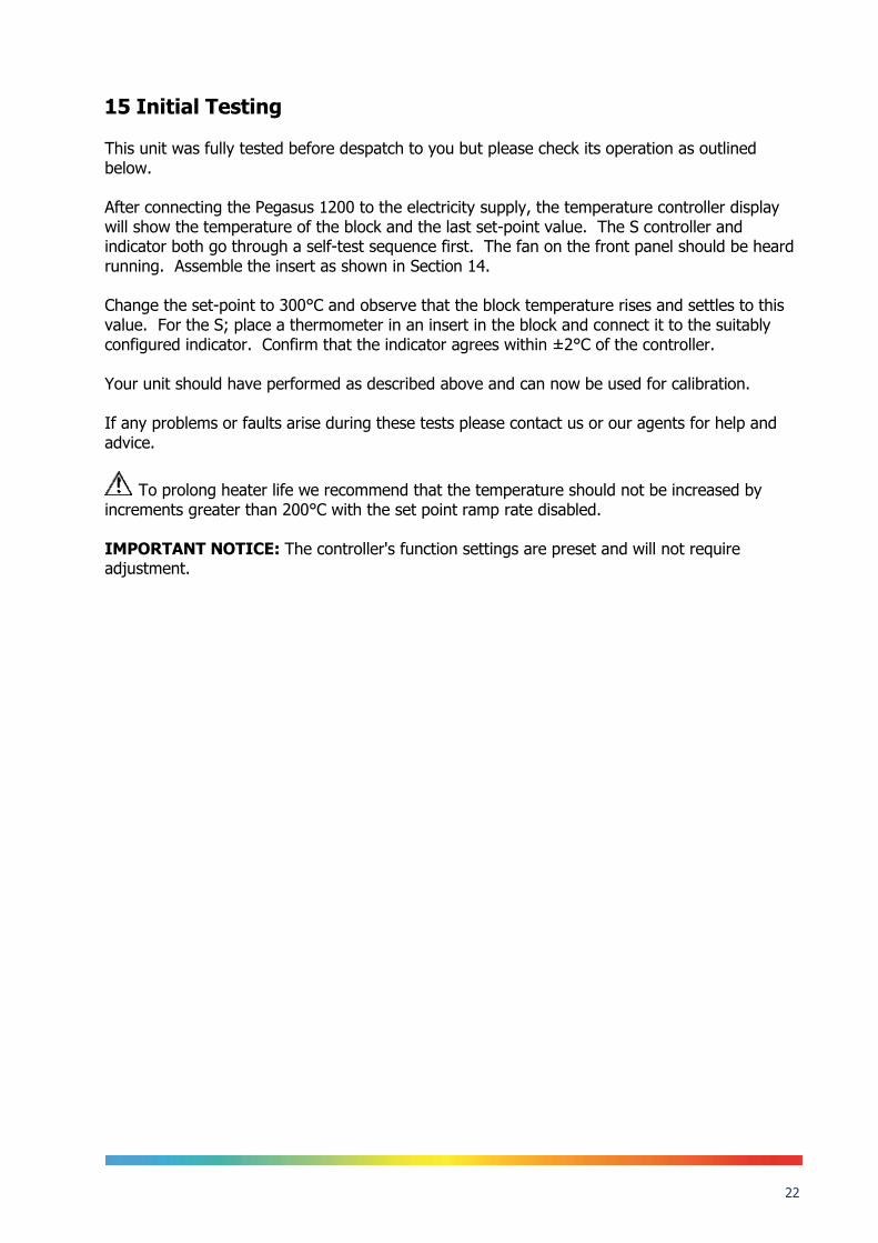
15 Initial Testing This unit was fully tested before despatch to you but please check its operation as outlined below. After connecting the Pegasus 1200 to the electricity supply, the temperature controller display will show the temperature of the block and the last set-point value. The S controller and indicator both go through a self-test sequence first. The fan on the front panel should be heard running. Assemble the insert as shown in Section 14. Change the set-point to 300°C and observe that the block temperature rises and settles to this value. For the S; place a thermometer in an insert in the block and connect it to the suitably configured indicator. Confirm that the indicator agrees within ±2°C of the controller. Your unit should have performed as described above and can now be used for calibration. If any problems or faults arise during these tests please contact us or our agents for help and advice.
To prolong heater life we recommend that the temperature should not be increased by increments greater than 200°C with the set point ramp rate disabled. IMPORTANT NOTICE: The controller's function settings are preset and will not require adjustment.

23
16 Fast Cool Down Probe (Option) The fast cool down probe can be attached to a suitable air supply and then placed into the Pegasus insert for rapid cooling.
Take care when placing the probe into the hot block. Ensure the air supply is set to give an appropriate flow rate. Guard against setting so high that the probe may be blown from the insert.

24
17 Pegasus 4853 Basic/Site - Maintenance Turn the electricity supply off before attempting any cleaning operation. The only moving part is the fan. It has sealed-for-life bearings. Depending on the environment in which it is used, periodic cleaning of the fan and the inside of the case is recommended. Cleaning may be accomplished by the use of a small dry paint brush. The instrument should be periodically checked to ensure it is in good order both mechanically and electrically.
17.1 The Basic Workings of the Pegasus 1200 The purpose of the Pegasus 1200 models is to provide an adjustable isothermal enclosure for calibration purposes. The isothermal enclosure consists of a small furnace into which an insert can be placed. Items for calibration are placed in suitably drilled holes in the insert. The replaceable inserts enable a variety of items to be calibrated. The furnace consists of a specially wound tube assembly. A control sensor is used by the temperature controller to sense the furnace temperature. To obtain and maintain a required temperature the controller varies the power to the heaters via a solid state relay. An internal fan runs continuously and cools the electronics in the instrument.
17.2 Operating Procedures The following operating procedures have been written for one of the two models as indicated by the Procedures heading. Please Note: no oils, greases or powders should be introduced into the Pegasus 4853 or its inserts.

25
18 Checking using the Temperature Indicated on the Controller 1. Remove the Pegasus 4853 from its case and visually inspect it for any damage it may have
sustained since it was last used. Insert the required metal insert into the furnace block using the tool supplied to avoid damage to the heater assembly.
2. Connect the Pegasus 4853 to a suitable power supply and set the controller to the required
temperature. 3. Place the thermometer for calibration into a suitable hole in the metal insert and wait for
the temperature to stabilise. 4. When the temperature indicated by the controller and the output of the thermometer are
both stable (see specification for typical values) record three sets of readings over a period of about six minutes. Check that these readings are consistent and then calculate their average values.
5. If the Pegasus 4853 has itself been calibrated, correct the average values accordingly. 6. Reset the controller and/or repeat the calibration for another thermometer. 7. When the calibration is complete, reset the controller to 0°C and wait until the unit has
cooled to below 600°C before moving the Pegasus 4853 to a new location. The Pegasus 4853 must be cooled below 100°C before it can be put back into its carrying case.
26
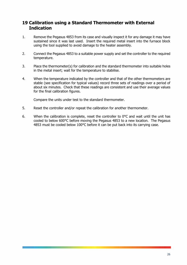
19 Calibration using a Standard Thermometer with External Indication
1. Remove the Pegasus 4853 from its case and visually inspect it for any damage it may have
sustained since it was last used. Insert the required metal insert into the furnace block using the tool supplied to avoid damage to the heater assembly.
2. Connect the Pegasus 4853 to a suitable power supply and set the controller to the required
temperature. 3. Place the thermometer(s) for calibration and the standard thermometer into suitable holes
in the metal insert; wait for the temperature to stabilise. 4. When the temperature indicated by the controller and that of the other thermometers are
stable (see specification for typical values) record three sets of readings over a period of about six minutes. Check that these readings are consistent and use their average values for the final calibration figures.
Compare the units under test to the standard thermometer.
5. Reset the controller and/or repeat the calibration for another thermometer. 6. When the calibration is complete, reset the controller to 0°C and wait until the unit has
cooled to below 600°C before moving the Pegasus 4853 to a new location. The Pegasus 4853 must be cooled below 100°C before it can be put back into its carrying case.

27
20 Calibration using a standard thermometer and the internal indicator
1. Remove the Pegasus 4853 from its case and visually inspect it for any damage it may
have sustained since it was last used. Insert the required metal insert into the furnace block using the tool supplied to avoid damage to the heater assembly.
2. Connect the Pegasus 4853 to a suitable power supply and set the controller to the
required temperature. 3. Place the thermometer(s) for calibration into a suitable insert(s) in the metal block and
wait for the temperature to stabilise, connect the standard thermometer to the indicator.
Ensure the indicator is configured for the correct sensor and where applicable the calibration data has been entered and user calibration enable – refer to Section 23.
4. When the temperature indicated by the controller and that of the other thermometers
are stable (see specification for typical values) record three sets of readings over a period of about six minutes. Check that these readings are consistent and use their average values for the final calibration figures.
5. Compare the units under test to the value from the in-built indicator. 6. If the Pegasus 4853 has been calibrated, correct the figures accordingly. 7. Reset the controller and/or repeat the calibration for another thermometer. 8. When the calibration is complete, reset the controller to 0°C and wait until the unit has
cooled to below 600°C before moving the Pegasus 4853 to a new location. The Pegasus 4853 must be cooled to below 100°C before it can be put back into its carrying case.

28
21 Calibration using the internal indicator to read a standard and unknown thermometers
1. Remove the Pegasus 4853 from its case and visually inspect it for any damage it may have
sustained since it was last used. Insert the required metal insert into the furnace block using the tool supplied to avoid damage to the heater assembly.
2. Connect the Pegasus 4853 to a suitable power supply and set the controller to the required
temperature. 3. Place the thermometer(s) for calibration and the standard thermometer into suitable holes
in the metal insert; wait for the temperature to stabilise. 4. When the temperature indicated by the controller and the standard are stable (see
specification for typical values) record the reading of the standard. Connect the thermometer under test, in place of the standard, to the indicator and re-reconfigure the indicator for the new sensor type as necessary if user calibration is enable for the standard it will need to be turned off or modified for the unit under test – refer to Section 23. Record the temperature of the thermometer under test. For security reconnect the standard thermometer, reconfigure the indicator and make sure the temperature has not changed from the first reading.
5. If the Pegasus 4853 has itself been calibrated, correct the average values accordingly. 6. Reset the controller and/or repeat the calibration for another thermometer. 7. When the calibration is complete, reset the controller to 0°C and wait until the unit has
cooled to below 600°C before moving the Pegasus 4853 to a new location. The Pegasus 4853 must be cooled to below 100°C before it can be put back into its carrying case.

29
22 Using the indicator to measure temperatures remote from the furnace
1. Remove the Pegasus 4853 from its case and visually inspect it for any damage it may
have sustained since it was last used. Insert the required metal insert into the furnace block using the tool supplied to avoid damage to the heater assembly.
2. Connect the Pegasus 4853 to a suitable power supply and set the controller to either 0°C
if the furnace is not to be used or to the required temperature if it is going to be used to calibrate thermometers.
3. If the standard thermometer is going to be used to measure a temperature other than
the metal block, reconfigure and set the user calibration of the indicator accordingly. Connect the standard thermometer to the indicator which will now display its temperature.
4. If the indicator is going to be used to measure the temperature of a remote
thermometer, reconfigure and set the user calibration of the indicator to correspond to that type of thermometer, connect the thermometer to the indicator and the corresponding temperature will be displayed. Refer to Section 23 for details of user calibration.
5. If the Pegasus 4853 has itself been calibrated, correct the average values accordingly. 6. Reset the controller and/or repeat the calibration for another thermometer. 7. When the calibration is complete, reset the controller to 0°C and wait until the unit has
cooled to below 600°C before moving the Pegasus 4853 to a new location. The Pegasus 4853 must be cooled to below 100°C before it can be put back into its carrying case.

30
23 Operating The Model
23.1 Front Panel Layout
23.1.1 The Temperature Controller The controller has a dual display, the upper display indicates the nominal block temperature, and the lower display indicates the desired temperature or setpoint.
23.1.2 Altering the Setpoint To change the setpoint of the controller simply use the UP and DOWN keys to raise and lower the setpoint to the required value. The lower display changes to indicate the new setpoint.
23.2 Controller Features
23.2.1 Setpoint Ramp Rate By default the Dry Blocks are configured to heat and cool as quickly as possible. There may be some calibration applications where it is advantageous to limit the heating or cooling rate. An example might be when testing bimetallic thermostats; by forcing the Dry Block to heat at a controlled rate it is easier to determine the temperature at which the thermostat changes state. The Dry Block can have its heating rate limited with the Setpoint Ramp Rate feature. This feature is accessed from the Scroll key. Depress the key until the display shows, SP.RAT The upper display will show the current value, and is adjustable from OFF to 999.9. The units are °C/min and are adjustable via the UP/DOWN keys. When the SP.RAT is active the lower setpoint display will now automatically update with the current value, known as the working setpoint. The setpoint can be seen by pressing either the UP and DOWN key. The Setpoint ramp rate operates when the bath is heating and cooling.

31
23.2.2 Instrument Address The controller has a configurable "address" which is used for PC communications. Each instrument has an address; this allows several instruments to be connected in parallel on the same communications bus. The default value is 1. This address would only need to be changed if more than one Dry Block is connected to the same PC port. To check the Address value press the scroll key until the lower display indicates, ADDR The upper display will show the current value that can be modified with the UP and DOWN keys.
23.3 Monitoring The Controller Status A row of beacons indicate the controllers status as follows, OP1 Heat Output OP2 Cool Output (only for models which operate below 0°C) REM This beacon indicates activity on the PC interface For models fitted with cool down fans, such as the Calisto and Jupiter, the lower display will alternate between the setpoint and the message, cooling to temperature. This message is not an error but is showing that the cooling fan is operating. It will automatically switch off when the temperature is within 5°C of the setpoint.
23.3.1 Units Momentary pressing of the Scroll key will show the controller units °C or °F.

32
23.4 The Temperature Indicator: Site Models Only The Site models include an electronic temperature indicator. The indicator can be configured for the desired sensor type, and for custom calibration data. The customer calibration data can be set ON or OFF.
23.5 Connecting Temperature Sensors
23.5.1 Platinum Resistance Thermometers, PRTs Set the input type to suit from either the front panel of the Isotech Config Software utility. PRTs can be connected to Inputs P1 and P2. When connecting a PRT ensure the corresponding thermocouple input is not used, that is if connecting a PRT to Input P1 then Input T1 must not be used, is if connecting a PRT to Input P2 then Input T2 must not be used.
23.5.2 Input Connections The five pin cable plug to suit PRTs is part number 935-16-107. These are readily available, suppliers include RS Components (Part Number 129-8573) and Farnell (Part Number 112-2585). With three wire PRT connections ensure identical lead resistance in all three legs of the connection by using the same length and gauge of cables.
23.5.3 Connecting Thermocouples Set the input type to suit from either the front panel of the Isotech Config Software utility. Thermocouples can be connected to Inputs T1, T2 and T3. When connecting a thermocouple ensure the corresponding PRT input is not used, that is if connecting a thermocouple to Input T1 then Input P1 must not be used, is if connecting a thermocouple to Input T2 then Input P2 must not be used. Input connectors are the industry standard “miniature thermocouple plugs”.
23.5.4 Setting the Input Type A 100 Ohm resistance thermometer can be connected to the PRT Connector or a thermocouple may be connected to the miniature TC Connector. Ensure that only a PRT or a TC is connected at any one time. If a PRT and TC are connected simultaneously the indicator will read in error. Check that any sensor placed into the equipment is suitable for the temperature range. Sensors can be damaged if taken outside their normal operating limits.

33
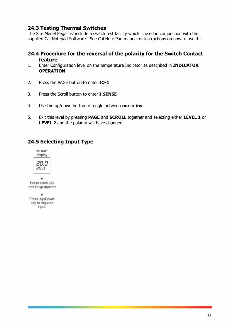
The desired sensor type is easily set, press the Scroll key until the lower display indicates, In.Typ The upper display will show the current set sensor type, J.tc J thermocouple K.tc K thermocouple L.tc L thermocouple r.tc R thermocouple (Pt/Pt13%Rh) b.tc B thermocouple (Pt30%Rh/Pt6%Rh) n.tc N thermocouple t.tc T thermocouple S.tc S thermocouple (Pt/Pt10%Rh) PL.2 PL 2 thermocouple rtd 100 Ohm platinum resistance thermometer. T012 E thermocouple Again the value can be modified with the UP and DOWN keys.
23.6 Enabling/Disabling Custom Calibration Custom calibration allows the indicator to be programmed to suit a particular temperature sensor. This allows the indicator to automatically show the true temperature, without having to manually apply a correction. When the Custom or User Calibration is active the indicator will show the REM beacon lit continuously. The use of User calibration can make a significant difference to the accuracy of the instrument, and this REM beacon provides a clear and continuous indication of the calibration status. Isotech will configure and set user calibration when the Dry Block is ordered with a temperature sensor. To alter the calibration status press the Scroll key until the lower display shows, UCAL The upper display will indicate either, ON for user calibration Or OFF for factory calibration of the indicator Use the UP and DOWN keys to toggle between the two values. When calibrating an unknown sensor against a calibrated probe it may be necessary to switch the calibration off for the unknown, and on for the calibrated probe.
23.7 Instrument Address Like the controller, the indicator has a configurable "address" which is used for PC communications. Each instrument has an address; this allows several instruments to be connected in parallel on the same communications bus. The default value is 2 (The controller defaults to 1).

34
This address would only need to be changed if more than one Dry Block is connected to the same PC port. To check the Address value press the scroll key until the lower display indicates, ADDR The upper display will show the current value that can be modified with the UP and DOWN keys.
23.8 Monitoring The Indicator Status For the indicator the REM beacon is lit continuously when the user calibration is active, the REM beacon flashes when the PC communications port is active.
23.8.1 Units Momentary pressing of the Scroll key will show the controller units °C or °F.
23.9 Indicator Operation The indicator can be configured with up to five custom calibration points; the points contain "data pairs". First the temperature (point) and secondly the Error (offset) at this temperature point. Isotech Dry Block calibration certificates will show the values to suit a particular sensor. These values can be inspected, and modified with the following procedure, Hold the PAGE key down until the display indicates, CONF GOTO then 0 CODE Set the Code to 2 with the UP key The display reads, CONF Press the Page Key until the controller shows CAL Now use the Scroll key to examine the data pairs. The values Pnt 1- Pnt 5 and Ofs 1 to Ofs 5 can be modified with the UP and DOWN keys. To exit this mode hold the Page key until the top display shows, CONF GOTO And then set the upper display to Lev 1. While in this mode take care not to modify other parameters.
35
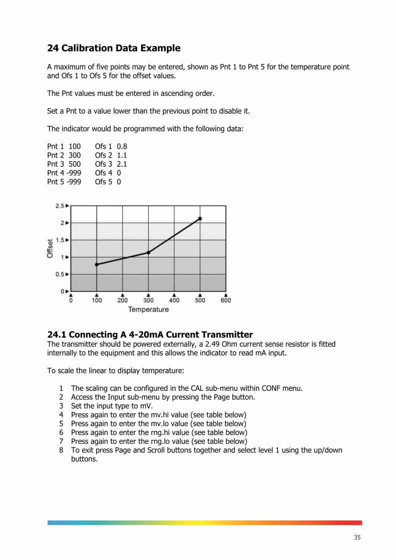
24 Calibration Data Example A maximum of five points may be entered, shown as Pnt 1 to Pnt 5 for the temperature point and Ofs 1 to Ofs 5 for the offset values. The Pnt values must be entered in ascending order. Set a Pnt to a value lower than the previous point to disable it. The indicator would be programmed with the following data: Pnt 1 100 Ofs 1 0.8 Pnt 2 300 Ofs 2 1.1 Pnt 3 500 Ofs 3 2.1 Pnt 4 -999 Ofs 4 0 Pnt 5 -999 Ofs 5 0
24.1 Connecting A 4-20mA Current Transmitter The transmitter should be powered externally, a 2.49 Ohm current sense resistor is fitted internally to the equipment and this allows the indicator to read mA input. To scale the linear to display temperature:
1 The scaling can be configured in the CAL sub-menu within CONF menu. 2 Access the Input sub-menu by pressing the Page button. 3 Set the input type to mV. 4 Press again to enter the mv.hi value (see table below) 5 Press again to enter the mv.lo value (see table below) 6 Press again to enter the rng.hi value (see table below) 7 Press again to enter the rng.lo value (see table below) 8 To exit press Page and Scroll buttons together and select level 1 using the up/down
buttons.

36

37
24.2 Using the Current Loop Interface 935-06-161 with the Site model
Connect the Transmitter to the equipment as shown in the above image. Note: do not connect 935-06-161 via the PRT socket. The Current Loop interface has built in resistance and does not require the internal resistance of the equipment. Connect via the Thermocouple socket only.
38
24.3 Testing Thermal Switches The Site Model Pegasus’ include a switch test facility which is used in conjunction with the supplied Cal Notepad Software. See Cal Note Pad manual or instructions on how to use this.
24.4 Procedure for the reversal of the polarity for the Switch Contact feature
1. Enter Configuration level on the temperature Indicator as described in INDICATOR
OPERATION
2. Press the PAGE button to enter IO-1
3. Press the Scroll button to enter I.SENSE
4. Use the up/down button to toggle between nor or inv
5. Exit this level by pressing PAGE and SCROLL together and selecting either LEVEL 1 or
LEVEL 2 and the polarity will have changed.
24.5 Selecting Input Type

39
25 Using The PC Interface The 4000 series models include an RS422 PC interface and a special converter cable that allows use with a standard RS232 port. When using the bath with an RS232 port it is essential that this converter cable is used. Replacement cables are available from Isotech, part number ISO-232-432. A further lead is available as an option, Part Number ISO-422-422 lead which permits up to 5 instruments to be daisy chained together. The benefit of this approach is that a number of calibration baths may be connected together in a "daisy chain" configuration - and then linked to a single RS232, see diagram.
Note: The RS 422 standard specifies a maximum lead length of 1200M (4000ft). A true RS422 port will be required to realise such lead lengths. The Isotech conversion leads are suitable for maximum combined lead lengths of 10M that is adequate for most applications.
25.1 Connections For RS232 use simply connect the Isotech cable. RS422 Connections Pin Connection 4 Tx+ A 5 Tx- B 8 Rx+ A 9 Rx- B 1 Common
25.2 Protocol The instruments use the "Modbus Protocol" If required, e.g. for writing custom software the technical details are available from our Document Library at www.isotech.co.uk

40
26 Cal Notepad Cal Notepad can be used can be used to log and display values from the Dry Blocks and an optional temperature indicator such as the milliK or TTI-10. The software requires Windows 9X, XP, a minimum of 5Mb of free hard drive space and free serial ports for the instruments to be connected.
26.1 Development Cal Notepad was developed by Isothermal Technology using LabVIEW from National Instruments. The license details are shown on the download page and in the Cal Notepad manual.
41
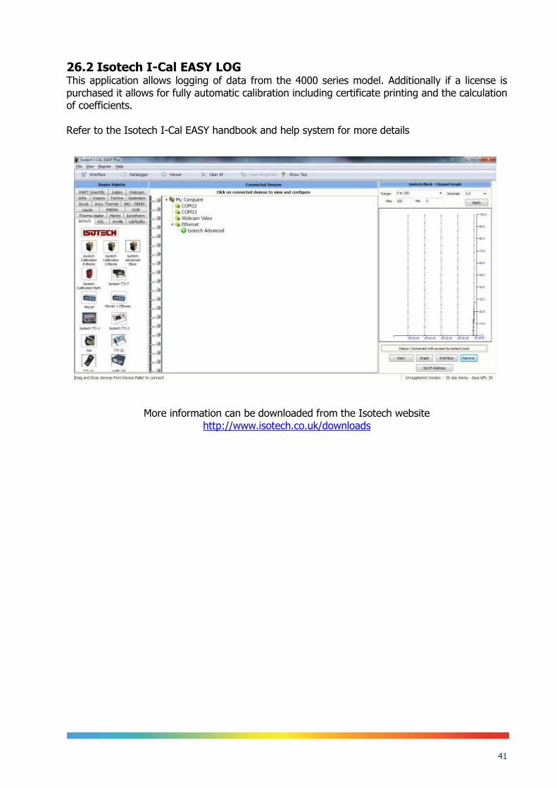
26.2 Isotech I-Cal EASY LOG This application allows logging of data from the 4000 series model. Additionally if a license is purchased it allows for fully automatic calibration including certificate printing and the calculation of coefficients. Refer to the Isotech I-Cal EASY handbook and help system for more details
More information can be downloaded from the Isotech website http://www.isotech.co.uk/downloads

42
27 Diagnostic Alarms Diagnostic alarms indicate a possible fault within the controller or connected devices.
Display shows
What it means What to do about it
E.Conf A change made to a parameter takes a finite time to be entered. If the power to the controller is turned off before the change has been entered then this alarm will occur. Do not turn the power off to the controller while ConF is flashing
Enter configuration mode then return to the required operating mode. It may be necessary to re-enter the parameter change since it will not have been entered in the previous configuration.
E.CaL Calibration error Re-instate Factory calibration, refer to Isotech
E2.Er EEPROM error Return to Isotech for repair
EE.Er Non-vol memory error Note the error and contact Isotech.
E.Lin Invalid input type. This refers to custom linearisation which may not have been applied correctly or may have been corrupted.
Go to the INPUT list in configuration level and set a valid thermocouple or input type
Emod IO1, OP2, or OP3 has been changed If this has been field changed by the installation of a new board, enter config level, then exit back to operator level. If the message occurs at any other time return to factory for repair.
Additional Information;
1. If the input is too high HHHHH will be displayed. 2. If the input is too low LLLLL will be displayed.

43
28 Appendix 1: Trouble Shooting
28.1.1 Large Temperature Difference Ensure the top and bottom ceramic insulators are in place – refer to Section 14 Ensure that all thermocouples are at the same depth.
28.1.2 Controller Lower Display Constantly Changes after setpoint change This is normal procedure.
28.1.3 Cannot establish PC Communications For RS232 you must use the Isotech adaptor cable. Ensure the addresses of the controller and indicator match those set in Cal Notepad. Ensure each controller and indicator are set to a unique address. Refer to ‘Using the PC Interface’ section and the Cal Notepad manual for further details.

44
29 Appendix 2: Indicator Configuration (Reference Only)
Config.INST Name Description Value
unit Instrument Units `C (0)
dEcP Decimal Places in Display NN.NN
CtrL Control Type PID (0)
Act Control Action REV (0)
COOL Cooling Type LIN (0)
PwrF Power Feedback Enable OFF (0)
Pdtr Manual/Auto Transfer PD Control
NO (0)
FoP Forced Output Enable NO (0)
Sbrt Sensor Break Type SB.OP (0)
rnGH Process Value High Limit 670
rnGL Process Value Low Limit 0.00
Config.IP Name Description Value
inPt Linearisation Type RTD
CJC CJC Type (EXT)
imP Sensor break impedance AUTO (1)
Config.CAL Name Description Value
UCAL User Calibration Enable YES (1)
Pnt1 User Cal Point 1 0
Pnt5 User Cal Point 5 -99.00
OFS1 User Cal Offset 1 0.00
Pnt2 User Cal Point 2 -99
OFS2 User Cal Offset 2 0.00
Pnt3 User Cal Point 3 -99
OFS3 User Cal Offset 3 0.00
Pnt4 User Cal Point 4 -99.00
OFS4 User Cal Offset 4 0.00
OFS5 User Cal Offset 5 -99.00 Note: User Cal values are unique to each instrument. If available set values to those from calibration certificate
45
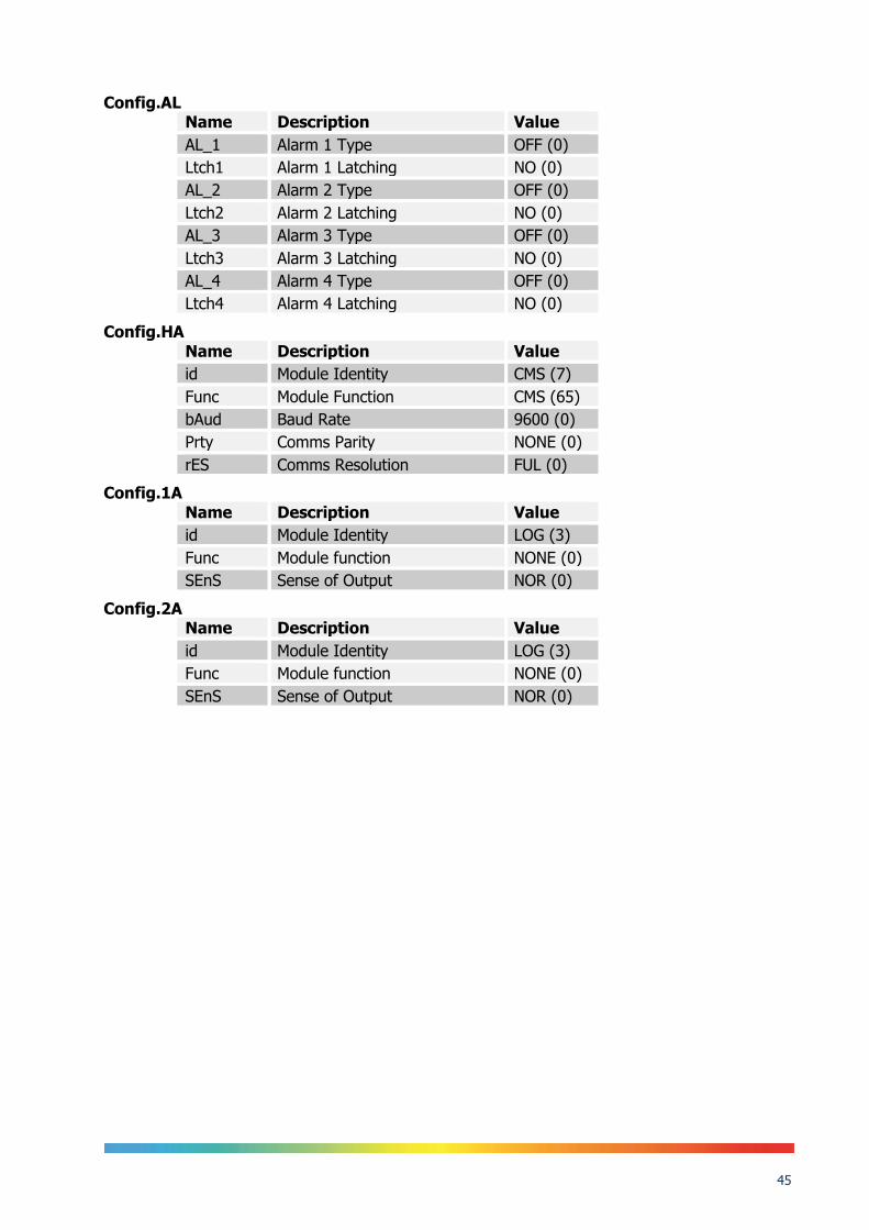
Config.AL Name Description Value
AL_1 Alarm 1 Type OFF (0)
Ltch1 Alarm 1 Latching NO (0)
AL_2 Alarm 2 Type OFF (0)
Ltch2 Alarm 2 Latching NO (0)
AL_3 Alarm 3 Type OFF (0)
Ltch3 Alarm 3 Latching NO (0)
AL_4 Alarm 4 Type OFF (0)
Ltch4 Alarm 4 Latching NO (0)
Config.HA Name Description Value
id Module Identity CMS (7)
Func Module Function CMS (65)
bAud Baud Rate 9600 (0)
Prty Comms Parity NONE (0)
rES Comms Resolution FUL (0)
Config.1A Name Description Value
id Module Identity LOG (3)
Func Module function NONE (0)
SEnS Sense of Output NOR (0)
Config.2A Name Description Value
id Module Identity LOG (3)
Func Module function NONE (0)
SEnS Sense of Output NOR (0)

46
30 Accessories Metal Block Bath Standard Metal Block Insert 4 x 8mm
853-06-01
Blank Dry Block Insert 853-06-02 Blackbody Use Blackbody Target Kit 853-06-03
Probes Standard Probe for On-Site Model 935-14-91
Current Loop Interface 935-06-161
Carrying Case 931-22-111