Embed Size (px)
Citation preview

User Maintenance Manual/Handbook
Issue 2.01
Software version 3.0.0+
Firmware version 3.0.0+
Isothermal Technology Limited, Pine Grove, Southport, PR9 9AG, EnglandIsothermal Technology Limited, Pine Grove, Southport, PR9 9AG, EnglandIsothermal Technology Limited, Pine Grove, Southport, PR9 9AG, EnglandIsothermal Technology Limited, Pine Grove, Southport, PR9 9AG, England
Tel: +44 (0)1704 543830 Fax: +44 (0)1704 544799 Internet: Tel: +44 (0)1704 543830 Fax: +44 (0)1704 544799 Internet: Tel: +44 (0)1704 543830 Fax: +44 (0)1704 544799 Internet: Tel: +44 (0)1704 543830 Fax: +44 (0)1704 544799 Internet: www.isotech.co.ukwww.isotech.co.ukwww.isotech.co.ukwww.isotech.co.uk
EEEE----mail: mail: mail: mail: [email protected]@[email protected]@isotech.co.uk
The company is always willing to give technical advice and assistance where appropriate. Equally,
because of the programme of continual development and improvement we reserve the right to amend
or alter characteristics and design without prior notice. This publication is for information only.
© Isothermal Technology Page 2 of 125 923 milliK manual - issue: 3.00
Contents
1 Introduction ........................................................................................................................ 6
1.1 Unpacking ................................................................................................................... 6
1.2 Safety ........................................................................................................................... 6
2 Getting Started ................................................................................................................... 9
2.1 A Quick Tour of Your milliK ................................................................................... 10
2.2 Driving your milliK ................................................................................................... 12
2.2.1 The ‘Graph’ Window ......................................................................................... 13
2.2.2 The ‘Numeric’ Window ..................................................................................... 13
2.2.3 The ‘Settings’ Window ...................................................................................... 14
2.2.4 The ‘Instrument’ Window.................................................................................. 16
2.3 Battery Operation ...................................................................................................... 17
3 Detailed Description by Function .................................................................................... 18
3.1 Using a PRT/SPRT with milliK ................................................................................ 18
3.1.1 Configuring milliK to measure a PRT/SPRT .................................................... 19
3.1.2 Determining Self-Heating of a PRT/SPRT ........................................................ 21
3.1.3 Using 3 or 4 Wire Measurement ........................................................................ 21
3.2 Using a Thermistor with milliK ................................................................................ 23
3.2.1 Configuring milliK to Measure Temperature with a Thermistor....................... 24
3.3 Using a Thermocouple with milliK ........................................................................... 25
3.3.1 Using Internal Reference Junction Compensation ............................................. 26
3.3.2 Using External Reference Junction Compensation............................................ 26
3.3.3 Using an Ice-Point for the Reference Junction .................................................. 27
3.3.4 Configuring milliK to Measure a Thermocouple............................................... 28
3.4 Using a 4-20mA Transmitter with milliK ................................................................. 30
3.4.1 Configuring milliK to Measure a 4-20mA Transmitter ..................................... 31
3.5 Measuring the Difference Between Two Channels................................................... 32
3.6 Changing Graph Scales ............................................................................................. 32
3.7 Using Rolling Statistics ............................................................................................. 33
3.8 Logging Results to a File .......................................................................................... 34
3.8.1 Transferring Logged Data to a PC ..................................................................... 36
3.8.2 File Format for Logged Data ............................................................................. 36
3.8.3 Clearing Logged Data from Internal Memory ................................................... 37
3.9 Using the Thermometer Database ............................................................................. 38
3.9.1 Creating a New Thermometer Entry .................................................................. 38
3.9.2 Using a PRT with IEC60751 (2008) Conversion .............................................. 40
3.9.3 Using a PRT with Callendar Van Dusen Conversion ........................................ 41
3.9.4 Using a PRT with ITS90 Conversion ................................................................ 42
3.9.5 Using a Thermocouple with Calibration Coefficients / Data Pairs.................... 43
3.9.6 Using a Thermistor with the Steinhart-Hart Polynomial ................................... 44
3.9.7 Using a Thermistor with Polynomial Temperature Conversion ........................ 45
3.9.8 Using a 4-20mA Transmitter with Linear Conversion ...................................... 46
3.10 Updating the Software ........................................................................................... 47
3.11 Using and Changing Passwords ............................................................................ 47
3.11.1 Recovering a Lost Password .............................................................................. 48
3.12 Controlling Temperature Sources with milliK ...................................................... 49
3.12.1 Creating a Temperature Profile .......................................................................... 51
4 Connecting Thermometers to milliK ............................................................................... 53
4.1 Connecting PRTs/SPRTs to milliK ........................................................................... 53
4.2 Connecting Thermistors to milliK............................................................................. 54
© Isothermal Technology Page 3 of 125 923 milliK manual - issue: 3.00
4.3 Connecting Thermocouples to milliK ....................................................................... 55
4.4 Connecting 4-20mA Transmitters to milliK ............................................................. 56
5 Calibration........................................................................................................................ 57
5.1 Standards Required for Calibration ........................................................................... 58
5.1.1 Making a 4-Terminal Short-Circuit ................................................................... 58
5.1.2 Making a 0mV Source in a Thermocouple Connector ...................................... 59
5.2 Checking the Calibration ........................................................................................... 59
5.2.1 PRT/SPRT Resistance Range ............................................................................ 60
5.2.2 Thermistor Resistance Range (500kΩ) – Span Check ...................................... 61
5.2.3 Thermocouple Voltage Range – Zero Check ..................................................... 62
5.2.4 Thermocouple Voltage Range – Span Check .................................................... 63
5.2.5 4-20mA Transmitter Range – Zero and Span Check ......................................... 63
5.2.6 Reference Junction Compensation Accuracy .................................................... 64
5.3 Adjusting the Calibration .......................................................................................... 66
5.3.1 Starting the Calibration Adjustment Feature ..................................................... 66
5.3.2 Adjusting SPRT (115Ω) Resistance Range ....................................................... 67
5.3.3 Adjusting PRT (460Ω) Resistance Range ......................................................... 68
5.3.4 Adjusting Thermistor (500kΩ) Resistance Range ............................................. 68
5.3.5 Adjusting Zero Voltage Offsets ......................................................................... 69
5.3.6 Adjusting Voltage Gain ..................................................................................... 69
5.3.7 Adjusting 4-20mA Transmitter Range............................................................... 70
5.3.8 Adjusting the RJC Sensor Calibration ............................................................... 71
5.4 Exporting Calibration information ............................................................................ 72
6 Maintenance and Cleaning ............................................................................................... 73
7 Interfacing to milliK ........................................................................................................ 74
7.1 Isotech Software ........................................................................................................ 74
7.2 RS232 Interface ......................................................................................................... 74
7.2.1 Establishing an RS232 Connection .................................................................... 75
7.3 Ethernet Interface ...................................................................................................... 78
7.3.1 Establishing an Ethernet Connection ................................................................. 78
7.3.1 Using SCPI Commands with the Ethernet Connection ..................................... 80
7.3.2 Using Remote Desktop Access .......................................................................... 81
8 SCPI Command Set ......................................................................................................... 83
8.1 Command Terminators .............................................................................................. 83
8.2 SCPI Command Structure ......................................................................................... 83
8.3 SCPI Numeric Suffices ............................................................................................. 84
8.4 Parameters ................................................................................................................. 84
8.5 Units .......................................................................................................................... 85
8.6 Making Measurements Using SCPI Commands ....................................................... 85
8.6.1 Measuring Resistance using SCPI Commands .................................................. 86
8.6.2 Measuring Voltage (with optional RJC) using SCPI Commands ...................... 86
8.6.3 Measuring Current using SCPI Commands ....................................................... 88
8.6.4 Measuring Temperature using SCPI Commands ............................................... 88
8.6.5 SCPI Commands ................................................................................................ 94
8.6.6 Command: *IDN? .............................................................................................. 96
8.6.7 Command [MILLik:]REMote ............................................................................ 96
8.6.8 Command [MILLik:]LOCal .............................................................................. 97
8.6.9 Command SENSe:FUNCtion[:ON] ................................................................... 98
8.6.10 Command SENSe:FUNCtion[:ON]? ................................................................. 98
8.6.11 Command SENSe:CHANnel ............................................................................. 98

© Isothermal Technology Page 4 of 125 923 milliK manual - issue: 3.00
8.6.12 Command SENSe:CHANnel? ........................................................................... 98
8.6.13 Command SENSe[:RESistance]:RANGe[:UPPer] ............................................ 99
8.6.14 Command SENSe[:RESistance:]RANGe[:UPPer]? .......................................... 99
8.6.15 Command SENSe:RESistance:WIRes............................................................... 99
8.6.16 Command SENSe:RESistance:WIRes? ........................................................... 100
8.6.17 Command SENSe:CURRent ........................................................................... 100
8.6.18 Command SENSe:CURRent? .......................................................................... 100
8.6.19 Command SENSe:PROBe ............................................................................... 101
8.6.20 Command SENSe:PROBe? ............................................................................. 101
8.6.21 Command SENSe:INITs .................................................................................. 101
8.6.22 Command SENSe:UNITs? .............................................................................. 102
8.6.23 Command SENSe:RJC .................................................................................... 102
8.6.24 Command SENSe:RJC?................................................................................... 102
8.6.25 Command INITiate[:IMMediate][:ALL] ......................................................... 102
8.6.26 Command FETCh[:SCALar]? ......................................................................... 103
8.6.27 Command READ[:SCALar]? .......................................................................... 103
8.6.28 Command MEASure[:SCALar]:TEMPerature<channel#>? ........................... 103
8.6.29 Command MEASure[:SCALar]:VOLTage[:DC]<channel#>? ....................... 104
8.6.30 Command MEASure[:SCALar]:RESistance<channel#> ................................ 105
8.6.31 Command MEASure[:SCALar]:CURRent? .................................................... 105
8.6.32 Command MEASure[:SCALar]:RJC? ............................................................. 106
8.6.33 Command PROBe:UNLock............................................................................. 106
8.6.34 Command PROBe:LOCK ................................................................................ 106
8.6.35 Command PROBe:COUNt? ............................................................................ 106
8.6.36 Command PROBe:NAMe<probe#> ................................................................ 106
8.6.37 Command PROBe:NAMe<probe#>? .............................................................. 107
8.6.38 Command PROBe:TYPe<probe#> .................................................................. 107
8.6.39 Command PROBe:TYPe<probe#>? ................................................................ 107
8.6.40 Command PROBe:MANufacturer<probe#> ................................................... 107
8.6.41 Command PROBe:MANufacturer<probe#>? ................................................. 108
8.6.42 Command PROBe:MODel<probe#> ............................................................... 108
8.6.43 Command PROBe:MODel<probe#>? ............................................................. 108
8.6.44 Command PROBe:SERial<probe#> ................................................................ 108
8.6.45 Command PROBe:SERial<probe#>? .............................................................. 108
8.6.46 Command PROBe:DATe<probe#> ................................................................. 109
8.6.47 Command PROBe:DATe<probe#>? ............................................................... 109
8.6.48 Command PROBe:MINimum<probe#> .......................................................... 109
8.6.49 Command PROBe:MINimum<probe#>? ........................................................ 109
8.6.50 Command PROBe:MAXimum<probe#> ........................................................ 110
8.6.51 Command PROBe:MAXimum<probe#>? ...................................................... 110
8.6.52 Command PROBe:WIRes<probe#> ................................................................ 110
8.6.53 Command PROBe:WIRes<probe#>? .............................................................. 111
8.6.54 Command PROBe:CONVersion<probe#> ...................................................... 111
8.6.55 Command PROBe:CONVersion<probe#>? .................................................... 112
8.6.56 Command PROBe:COEFficient<probe#> ...................................................... 112
8.6.57 Command PROBe:COEFficient<probe#>? ..................................................... 113
8.6.58 Command PROBe:CVD:FORM ...................................................................... 113
8.6.59 Command PROBe:CVD:FORM? .................................................................... 114
8.6.60 Command PROBe:ITS90:FORM<probe#> .................................................... 114
8.6.61 Command PROBe:ITS90:FORM<probe#>? ................................................... 114
© Isothermal Technology Page 5 of 125 923 milliK manual - issue: 3.00
8.6.62 Command PROBe:CREate .............................................................................. 114
8.6.63 Command PROBe:DELete<probe#> .............................................................. 115
8.6.64 Command PROBe:FIND? ............................................................................... 115
8.6.65 Command CALibrate:UNLock ........................................................................ 115
8.6.66 Command CALibrate:LOCK ........................................................................... 115
8.6.67 Command CALibrate:RESistance:GAIN ........................................................ 116
8.6.68 Command CALibrate:RESistance:GAIN? ...................................................... 116
8.6.69 Command CALibrate:VOLTage:OFFSet<channel#> ..................................... 116
8.6.70 Command CALibrate:VOLTage:OFFset<channel>? ...................................... 117
8.6.71 Command CALibrate:VOLTage:GAIN .......................................................... 117
8.6.72 Command CALibrate:VOLTage:GAIN? ......................................................... 117
8.6.73 Command CALibrate:CURRent:GAIN ........................................................... 118
8.6.74 Command CALibrate:CURRent:GAIN? ......................................................... 118
8.6.75 Command CALibrate:RJC:OFFSet ................................................................. 118
8.6.76 Command CALibrate:RJC:OFFSet? ............................................................... 119
8.6.77 Command CALibrate:IDENtification .............................................................. 119
8.6.78 Command CALibrate:IDENtification? ............................................................ 119
8.6.79 Command CALibrate:IDENtification:LAST? ................................................. 119
8.6.80 Command CALibrate:PASSword .................................................................... 120
8.6.81 Command CALibrate:VALid? ......................................................................... 120
9 Specification .................................................................................................................. 121
10 Approvals ....................................................................................................................... 124
10.1 CE Declaration .................................................................................................... 124
10.2 FCC Statement ..................................................................................................... 124
10.3 Standards Applied................................................................................................ 125
11 Revision History ............................................................................................................ 125
© Isothermal Technology Page 6 of 125 923 milliK manual - issue: 3.00
1 Introduction
The milliK precision thermometer provides a complete measurement and control interface for
users wishing to make high accuracy temperature measurements or calibrate thermometers. It
supports a wide range of thermometer types including 25Ω SPRTs, 100Ω PRTs, thermistors,
thermocouples and 4-20mA transmitters (self-powered and loop-powered) and can control
Isotech temperature sources, sequencing through a programmable list of temperature set
points whilst logging data to internal memory or a USB drive.
The milliK sets new measurement standards in its class (<±5ppm for SPRTs/PRTs, <±2µV
for thermocouples, <±50ppm for thermistors and <±0.01% for current transmitters). The
Windows™ CE operating system provides a simple and intuitive user interface and with a
wide range of interfaces (USB, RS232, ethernet) allows the user to access the comprehensive
features of the milliK. A USB keyboard and mouse can be plugged into the milliK to make
control and data entry with the milliK as simple as using a laptop PC.
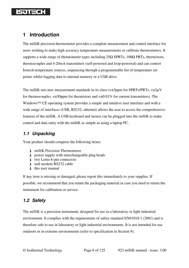
1.1 Unpacking
Your product should comprise the following items:
milliK Precision Thermometer
power supply with interchangeable plug heads
two Lemo 6-pin connectors
null modem RS232 cable
this user manual
If any item is missing or damaged, please report this immediately to your supplier. If
possible, we recommend that you retain the packaging material in case you need to return the
instrument for calibration or service.
1.2 Safety
The milliK is a precision instrument, designed for use in a laboratory or light industrial
environment. It complies with the requirements of safety standard EN61010-1 (2001) and is
therefore safe to use in laboratory or light industrial environments. It is not intended for use
outdoors or in extreme environments (refer to specification in Section 9).
© Isothermal Technology Page 7 of 125 923 milliK manual - issue: 3.00
!
The milliK is likely to be connected to thermometer sensors in use and the user should take
care to ensure that the complete system is safe. For example, metal sheathed thermometers
may be connected to the milliK and then placed in a furnace powered from a 230V electrical
supply. Single fault conditions in such a furnace could lead to the thermometer wires and the
front terminals of the milliK, to which they are connected, becoming electrically live and
therefore a hazard to the user. Suitable precautions should be taken, such as using an isolating
transformer in the supply to such a furnace. If you require further advice on safety issues,
please contact Isothermal Technology or one of our appointed distributors - we have
extensive experience of thermometry and can provide advice and equipment to help you.
Retain these instructions. Use only as specified in these operating instructions or the intrinsic
protection may be impaired.
Please observe the following safety precautions:
Do not use your milliK if it is damaged
Only connect the power supply to an electrical supply that conforms to the
specification given on its rating plate
This equipment is for indoor use within an ambient temperature range of 0°C to 40°C
with maximum relative humidity of 95%
This equipment is for use in moderate climates only. NEVER use the equipment in
damp or wet conditions
Avoid excessive heat, humidity, dust & vibration
Do not place liquid filled containers on the equipment
Do not use where the equipment (or any associated accessories) may be subjected to
dripping or splashing liquids
Ensure all cables and wires are routed safely to avoid tripping: also, to avoid sharp
bends and pinches
Clean only with a damp cloth. Do not wet or allow moisture to penetrate the
equipment. Do not use solvents; see section 6 for details of cleaning procedure
The product should be subjected to regular in-service inspections as required by local
regulations; a yearly interval is suggested
Do not apply earth test currents to any terminals nor to the shrouds of the USB,
RS232, or ethernet connectors
The product is designed to comply with EN 61010-1 and can be flash tested. It is
fitted with radio frequency interference suppressors. Therefore, it is recommended
that only a D.C. test be performed. Performing flash tests repeatedly can damage
insulation
This equipment contains no user-serviceable parts. Refer all repairs to qualified
service personnel. Contact Isothermal Technology or one of our appointed distributors
for details of approved service outlets
The power supply has been approved to the following safety standards:
UL60950-1, 2nd Edition: 2007-03-27
CSA C22.2 No. 60950-1-07, 2nd Edition: 2007-03

© Isothermal Technology Page 8 of 125 923 milliK manual - issue: 3.00
EN 60950-1: 2006 including A11
BS EN60950-1: 2006
AS/NZS60950-1: 2003 including amendments 1, 2 and 3
© Isothermal Technology Page 9 of 125 923 milliK manual - issue: 3.00
2 Getting Started
The power supply operates from any standard AC electrical supply (90-264V RMS at 47-
63Hz), so unless your supply is unusual you can simply connect the power supply to a
suitable electrical outlet.
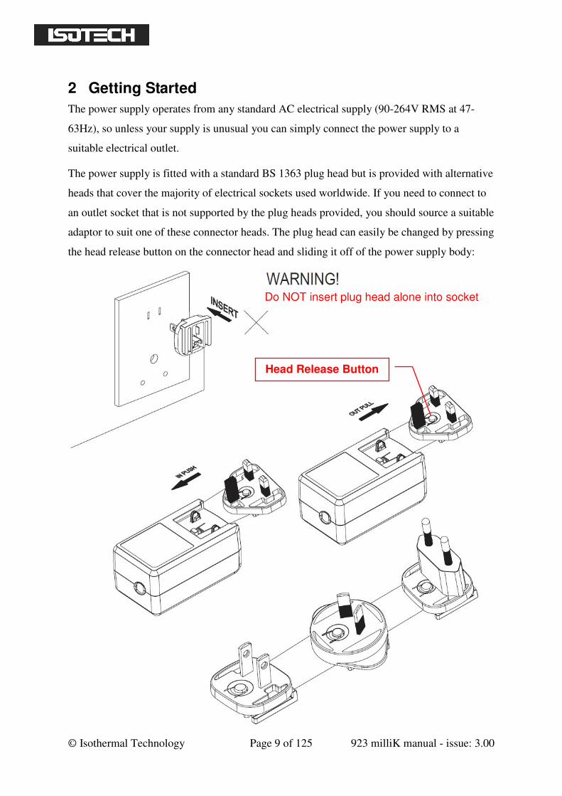
The power supply is fitted with a standard BS 1363 plug head but is provided with alternative
heads that cover the majority of electrical sockets used worldwide. If you need to connect to
an outlet socket that is not supported by the plug heads provided, you should source a suitable
adaptor to suit one of these connector heads. The plug head can easily be changed by pressing
the head release button on the connector head and sliding it off of the power supply body:
Head Release Button
Do NOT insert plug head alone into socket

© Isothermal Technology Page 10 of 125 923 milliK manual - issue: 3.00
Plug the DC connector from the power supply into the “DC Power” socket on the rear of the
milliK. Press the on/off button on the front panel to turn on your milliK. The milliK will load
the operating system and software (25s) and then restore itself to the settings used when it
was de-powered. This manual provides comprehensive details on using your milliK. In
addition video tutorials are available on the Isotech website (see video tab at
www.isotech.co.uk/precision-thermometers/instruments/instruments/millik-precision-
thermometer).
2.1 A Quick Tour of Your milliK
On the front of your milliK you will find two sets of connectors (Lemo 6-pin circular
connectors for SPRTs/PRTs/thermistors and miniature thermocouple connectors) for
channels 1 and 2. On the rear of your milliK you will find the 4mm sockets for channel 3
(used exclusively for 4-20mA transmitters).
Colour
LCD
Up/Down/
Left/Right/
Enter keys
Context
Sensitive
Function
Keys
Channel 1
Lemo
Connector
Channel 1
Miniature
Thermocouple
Connector
Channel 2
Lemo
Connector
Channel 2
Miniature
Thermocouple
Connector
On/Off
Button
Tilt
Feet
© Isothermal Technology Page 11 of 125 923 milliK manual - issue: 3.00
The milliK is controlled using the ←←←← →→→→ ↑↑↑↑ ↓↓↓↓ ↵↵↵↵ (left/right/up/down/enter) key cluster and the
4 function keys located below the display. The ←←←← →→→→ ↑↑↑↑ ↓↓↓↓ keys are used to navigate between
items on the screen and the ↵↵↵↵ key is used to select or toggle the highlighted item. The
function keys select the context sensitive function displayed above each key. The milliK will
display soft keyboards when required so that all features of the milliK can be accessed using
these keys. You can also connect a keyboard and/or mouse to the USB port (rear panel) and
use these to control the milliK. The function keys below the display are mapped to keys F1-
F4 on the keyboard so that you can control the milliK completely using a USB keyboard.
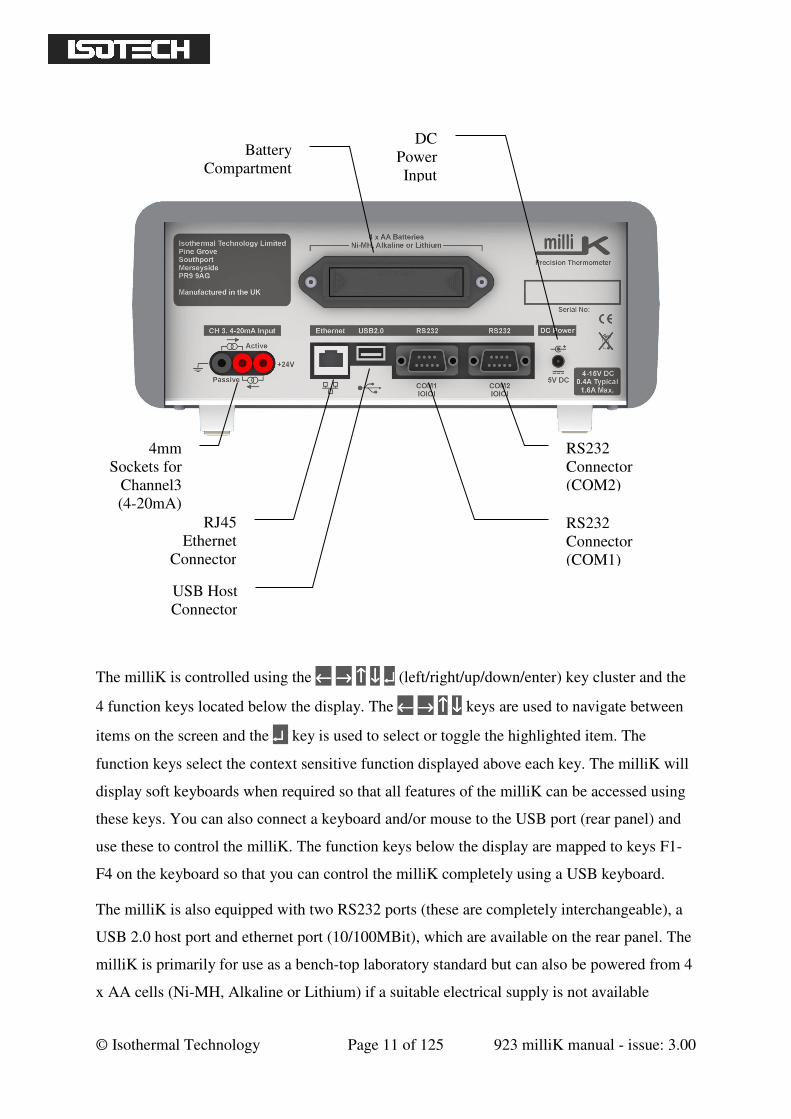
The milliK is also equipped with two RS232 ports (these are completely interchangeable), a
USB 2.0 host port and ethernet port (10/100MBit), which are available on the rear panel. The
milliK is primarily for use as a bench-top laboratory standard but can also be powered from 4
x AA cells (Ni-MH, Alkaline or Lithium) if a suitable electrical supply is not available
Battery
Compartment
DC
Power
Input
RJ45
Ethernet
Connector
USB Host
Connector
RS232
Connector
(COM1)
RS232
Connector
(COM2)
4mm
Sockets for
Channel3
(4-20mA)
© Isothermal Technology Page 12 of 125 923 milliK manual - issue: 3.00
(typical rechargeable Ni-MH cells provide > 4 hours operating life). The battery compartment
is located on the rear panel.
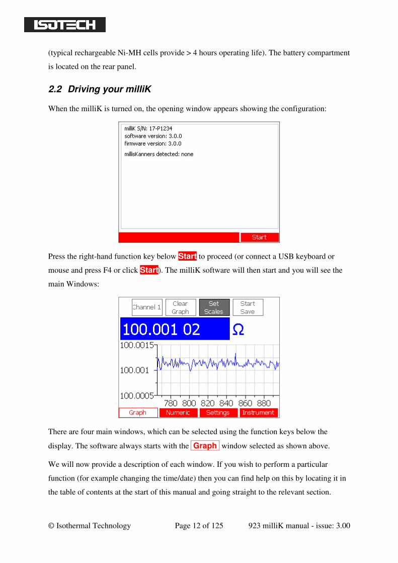
2.2 Driving your milliK
When the milliK is turned on, the opening window appears showing the configuration:
Press the right-hand function key below Start to proceed (or connect a USB keyboard or
mouse and press F4 or click Start). The milliK software will then start and you will see the
main Windows:
There are four main windows, which can be selected using the function keys below the
display. The software always starts with the Graph window selected as shown above.
We will now provide a description of each window. If you wish to perform a particular
function (for example changing the time/date) then you can find help on this by locating it in
the table of contents at the start of this manual and going straight to the relevant section.
© Isothermal Technology Page 13 of 125 923 milliK manual - issue: 3.00
2.2.1 The ‘Graph’ Window
In the Graph window you can view a single channel (or the difference between any
channel and Channel 1) in graphical and numerical form. Functions available from within this
window are:
Select which channel (or the difference between which channel and channel 1) to
view
Clear the graph
Set the scales for the graph (automatic scaling available for vertical axis)
Start/stop logging of data to internal or external (USB drive) memory
Use the ←←←←→→→→ keys to select from the buttons displayed at the top of the screen and press the ↵↵↵↵
key to activate that function (for example, to clear the statistics). To change which channel is
displayed (or to select a difference) use the ←←←←→→→→ keys to select the right-hand button and
either use the ↑↑↑↑↓↓↓↓ keys to sequence through the channels or press the ↵↵↵↵ key to open a window
containing a list of all the available channels. Only channels that are enabled (in the ‘Settings’
window) appear, so if only one channel is enabled this button has no effect.
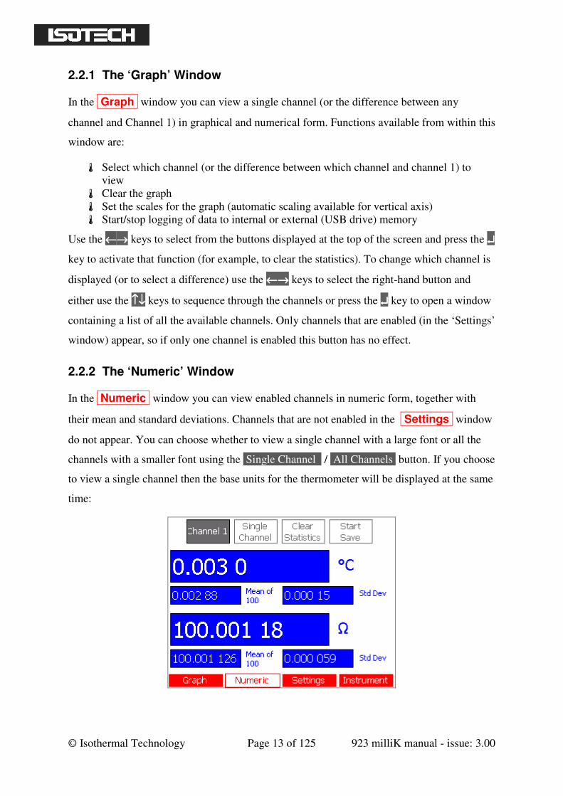
2.2.2 The ‘Numeric’ Window
In the Numeric window you can view enabled channels in numeric form, together with
their mean and standard deviations. Channels that are not enabled in the Settings window
do not appear. You can choose whether to view a single channel with a large font or all the
channels with a smaller font using the Single Channel / All Channels button. If you choose
to view a single channel then the base units for the thermometer will be displayed at the same
time:
© Isothermal Technology Page 14 of 125 923 milliK manual - issue: 3.00
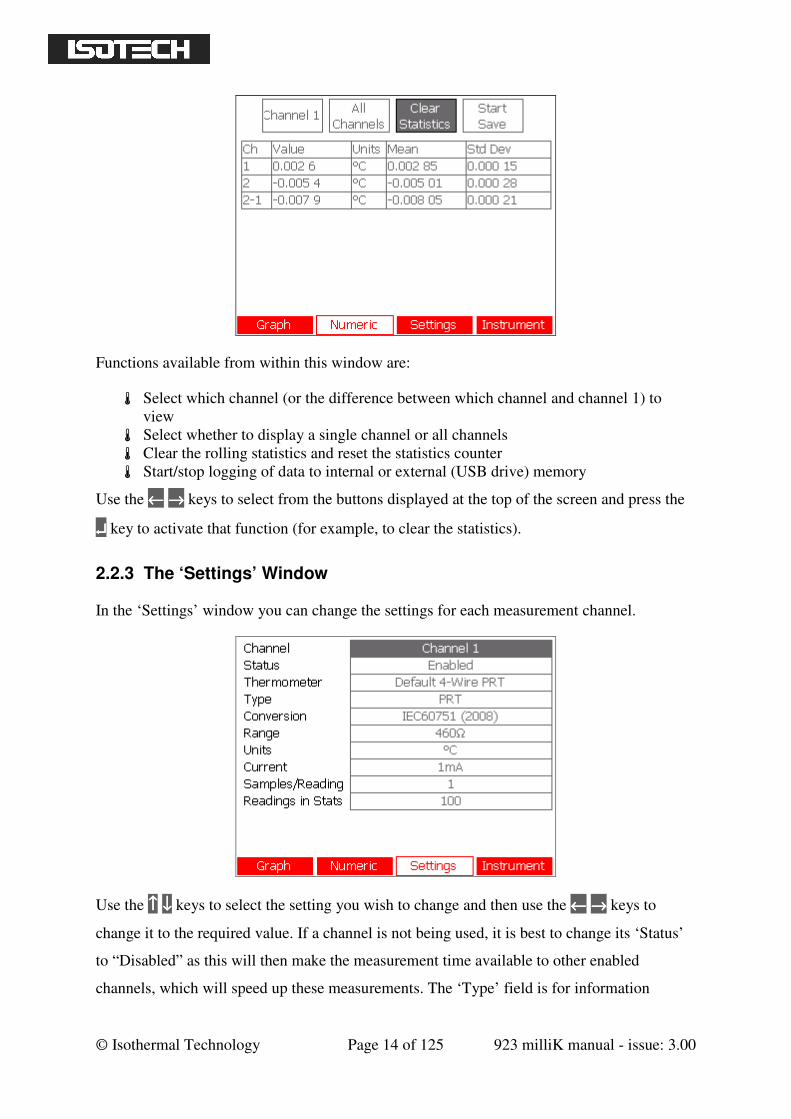
Functions available from within this window are:
Select which channel (or the difference between which channel and channel 1) to
view
Select whether to display a single channel or all channels
Clear the rolling statistics and reset the statistics counter
Start/stop logging of data to internal or external (USB drive) memory
Use the ←←←← →→→→ keys to select from the buttons displayed at the top of the screen and press the
↵↵↵↵ key to activate that function (for example, to clear the statistics).
2.2.3 The ‘Settings’ Window
In the ‘Settings’ window you can change the settings for each measurement channel.
Use the ↑↑↑↑ ↓↓↓↓ keys to select the setting you wish to change and then use the ←←←← →→→→ keys to
change it to the required value. If a channel is not being used, it is best to change its ‘Status’
to “Disabled” as this will then make the measurement time available to other enabled
channels, which will speed up these measurements. The ‘Type’ field is for information
© Isothermal Technology Page 15 of 125 923 milliK manual - issue: 3.00
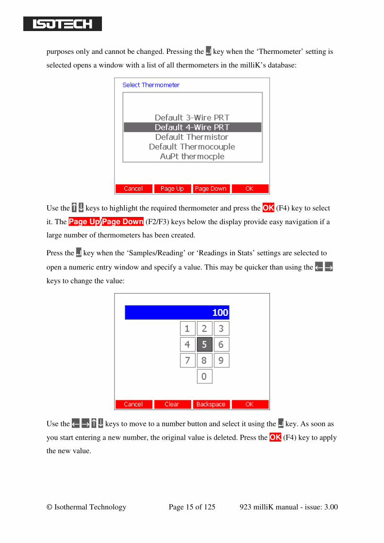
purposes only and cannot be changed. Pressing the ↵↵↵↵ key when the ‘Thermometer’ setting is
selected opens a window with a list of all thermometers in the milliK’s database:
Use the ↑↑↑↑ ↓↓↓↓ keys to highlight the required thermometer and press the OK (F4) key to select
it. The Page Up/Page Down (F2/F3) keys below the display provide easy navigation if a
large number of thermometers has been created.
Press the ↵↵↵↵ key when the ‘Samples/Reading’ or ‘Readings in Stats’ settings are selected to
open a numeric entry window and specify a value. This may be quicker than using the ←←←← →→→→
keys to change the value:
Use the ←←←← →→→→ ↑↑↑↑ ↓↓↓↓ keys to move to a number button and select it using the ↵↵↵↵ key. As soon as
you start entering a new number, the original value is deleted. Press the OK (F4) key to apply
the new value.
© Isothermal Technology Page 16 of 125 923 milliK manual - issue: 3.00
The ‘Samples/Reading’ setting is initially set to 1 but can be increased to a maximum of 100.
This will cause the milliK to take the specified number of samples for each reading and will
reduce the noise at the expense of slower measurement speed.
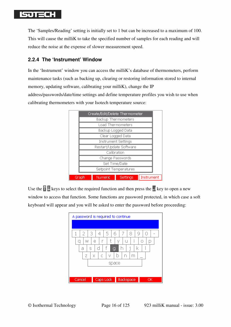
2.2.4 The ‘Instrument’ Window
In the ‘Instrument’ window you can access the milliK’s database of thermometers, perform
maintenance tasks (such as backing up, clearing or restoring information stored to internal
memory, updating software, calibrating your milliK), change the IP
address/passwords/date/time settings and define temperature profiles you wish to use when
calibrating thermometers with your Isotech temperature source:
Use the ↑↑↑↑ ↓↓↓↓ keys to select the required function and then press the ↵↵↵↵ key to open a new
window to access that function. Some functions are password protected, in which case a soft
keyboard will appear and you will be asked to enter the password before proceeding:

© Isothermal Technology Page 17 of 125 923 milliK manual - issue: 3.00
Use the ←←←← →→→→ ↑↑↑↑ ↓↓↓↓ keys to move to a button and select it using the ↵↵↵↵ key. Press OK to enter
the password. A separate password is provided to protect the calibration of the milliK. Both
passwords are initially set to “1234” but should be changed prior to use in order to ensure the
security of measurements made using your milliK (see section 3.11). A password recovery
process is available if you forget your password, please contact Isothermal Technology or its
approved distributor for assistance if required (see section 3.11.1).
2.3 Battery Operation
The milliK is primarily intended for use as an AC powered, bench-top instrument and is
supplied with a universal power supply for this purpose. However, it may also be powered
from batteries (not supplied) so that it can be used where an AC electrical supply is not
available.
The battery compartment is located on the rear panel. To gain access, squeeze the tabs on the
sides of the battery drawer and slide it out. The battery compartment accepts four AA size
cells.
The milliK can use primary (alkaline or lithium) cells or rechargeable (NiMH) cells. Lithium
cells provide the longest battery life (>6 hours), but are expensive and are not rechargeable.
Rechargeable NiMH cells provide good battery life (> 4 hours) and being rechargeable offer
low running costs, they are therefore the recommended solution for users wishing to use the
battery powered option. Alkaline cells can be used, but they provide limited operating life;
tests have shown that alkaline cells offer half the operating life of NiMH cells with the same
quoted capacity (mAh) because they have a higher output impedance during discharge
(leading to a lower output voltage).
© Isothermal Technology Page 18 of 125 923 milliK manual - issue: 3.00
3 Detailed Description by Function
This section describes all the features available on the milliK by function. If you wish to learn
how to do something with your milliK use the table of contents on page 2 onwards to look up
the appropriate section.
3.1 Using a PRT/SPRT with milliK
The milliK can measure the resistance of PRTs and SPRTs. It can convert measurements
from resistance to temperature units (K, °C or °F) so that you can make precise temperature
measurements or calibrate other thermometers from a reference standard.
The milliK provides two resistance measurement ranges which are optimised for PRTs and
SPRTs:
• 0-115Ω: optimised for 25.5Ω SPRTs
• 0-460Ω: optimised for 100Ω PRTS
The milliK will measure 25.5Ω SPRTs on the 460Ω range, but better measurement
uncertainty is achieved by using the 115Ω range. The sense current for both ranges is 1mA
(or 1.428mA).
Connect your PRTs/SPRTs to either of the Lemo 6-pin circular connectors on the front panel
(see section 4.1 for pin-out and connection details). Ensure that the miniature thermocouple
connector for the same channel is unused (since it is connected in parallel with the Lemo
connector). Isotech can (optionally) supply thermometers fitted with a suitable Lemo
connector. Your milliK is supplied with two Lemo connectors for you to use with your own
PRT/SPRT (or thermistor). The part number for this connector is:
Lemo part number: FGG.1B.306.CLAD62Z
Additional connectors are readily available internationally from Farnell Electronics and can
be ordered via their website www.farnell.com (Farnell stock code 3817325).
Channels 1 and 2 are not isolated from each other, but are isolated from Channel 3 and from
the digital interfaces in order to optimise immunity to external noise sources.
© Isothermal Technology Page 19 of 125 923 milliK manual - issue: 3.00
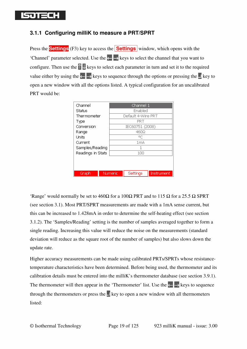
3.1.1 Configuring milliK to measure a PRT/SPRT
Press the Settings (F3) key to access the Settings window, which opens with the
‘Channel’ parameter selected. Use the ←←←← →→→→ keys to select the channel that you want to
configure. Then use the ↑↑↑↑ ↓↓↓↓ keys to select each parameter in turn and set it to the required
value either by using the ←←←← →→→→ keys to sequence through the options or pressing the ↵↵↵↵ key to
open a new window with all the options listed. A typical configuration for an uncalibrated
PRT would be:
‘Range’ would normally be set to 460Ω for a 100Ω PRT and to 115 Ω for a 25.5 Ω SPRT
(see section 3.1). Most PRT/SPRT measurements are made with a 1mA sense current, but
this can be increased to 1.428mA in order to determine the self-heating effect (see section
3.1.2). The ‘Samples/Reading’ setting is the number of samples averaged together to form a
single reading. Increasing this value will reduce the noise on the measurements (standard
deviation will reduce as the square root of the number of samples) but also slows down the
update rate.
Higher accuracy measurements can be made using calibrated PRTs/SPRTs whose resistance-
temperature characteristics have been determined. Before being used, the thermometer and its
calibration details must be entered into the milliK’s thermometer database (see section 3.9.1).
The thermometer will then appear in the ‘Thermometer’ list. Use the ←←←← →→→→ keys to sequence
through the thermometers or press the ↵↵↵↵ key to open a new window with all thermometers
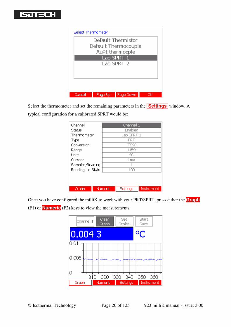
listed:
© Isothermal Technology Page 20 of 125 923 milliK manual - issue: 3.00
Select the thermometer and set the remaining parameters in the Settings window. A
typical configuration for a calibrated SPRT would be:
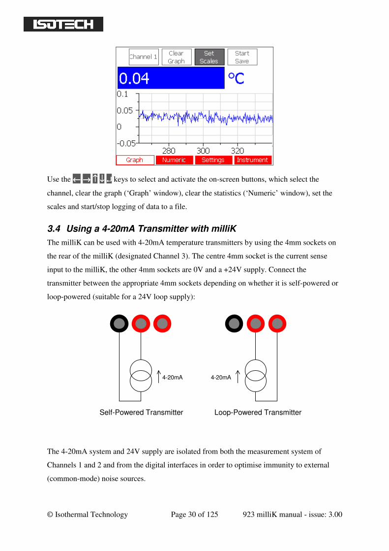
Once you have configured the milliK to work with your PRT/SPRT, press either the Graph
(F1) or Numeric (F2) keys to view the measurements:
© Isothermal Technology Page 21 of 125 923 milliK manual - issue: 3.00
Use the ←←←← →→→→ ↑↑↑↑ ↓↓↓↓ ↵↵↵↵ keys to navigate between and select the on-screen buttons, which select
the channel, clear the graph (‘Graph’ window), clear the statistics (‘Numeric’ window), set
the scales or start/stop logging of data to a file.
3.1.2 Determining Self-Heating of a PRT/SPRT
The normal sense current used by the milliK for PRTs/SPRTs is 1mA. This current causes a
small amount of self-heating in the thermometer (typically 1 to 3mK). Provided that the
thermometer is calibrated and used at the same current, this leads to negligible uncertainty in
the measurement.
In some special applications the self-heating effect is a significant source of measurement
uncertainty and it may be necessary to determine the amount of self-heating in the
thermometer. This is easily achieved by varying the sense current and observing the change
in indicated temperature. The milliK provides a feature that allows the sense current to be
increased by a factor of 1.428 ( mA), which increases the power dissipated by a factor
of two (since power is proportional to current squared). The change in indicated reading
caused by this change is then a direct measure of the self-heating effect at the normal 1mA
sense current (if the self-heating effect at 1mA is δT, then the self-heating at mA is 2δT
and the difference between the two readings is 2δT - δT i.e. δT). Subtracting the change (δT)
from the value at 1mA gives the resistance without any self-heating.
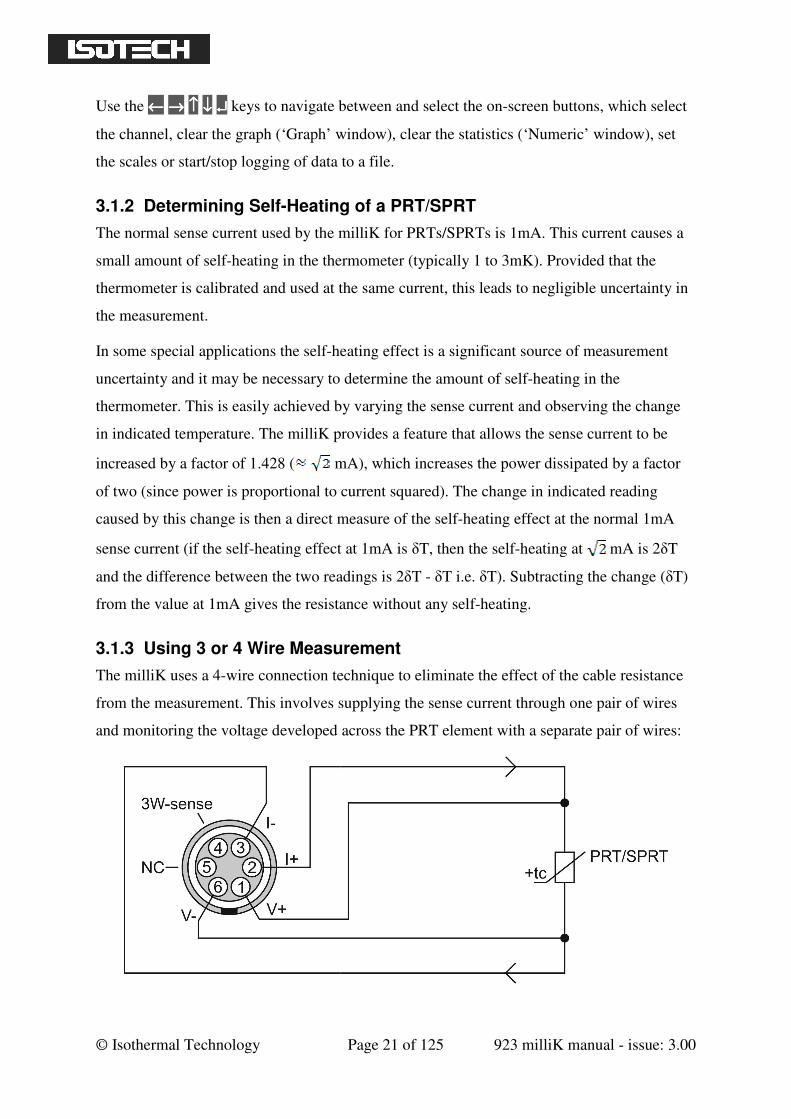
3.1.3 Using 3 or 4 Wire Measurement
The milliK uses a 4-wire connection technique to eliminate the effect of the cable resistance
from the measurement. This involves supplying the sense current through one pair of wires
and monitoring the voltage developed across the PRT element with a separate pair of wires:
© Isothermal Technology Page 22 of 125 923 milliK manual - issue: 3.00
Since the current along the voltage sense wires is effectively zero, the milliK is able to
measure the resistance of the PRT element without being affected by the resistance of the
wires.
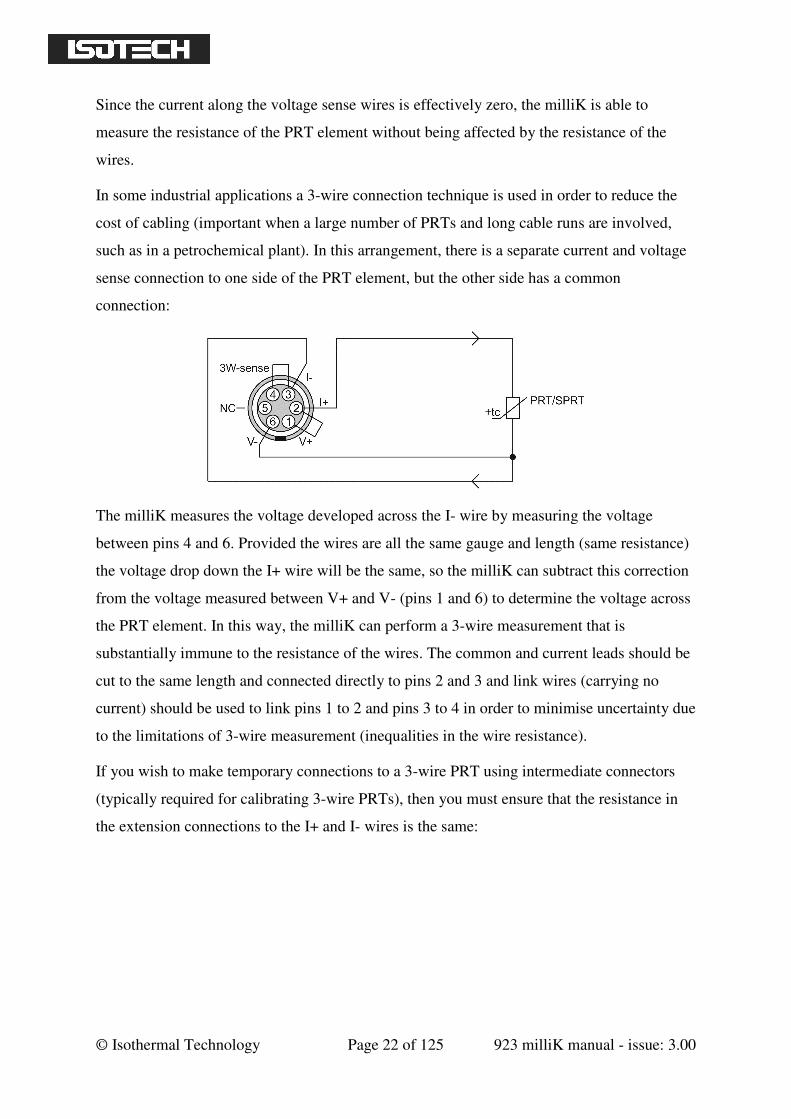
In some industrial applications a 3-wire connection technique is used in order to reduce the
cost of cabling (important when a large number of PRTs and long cable runs are involved,
such as in a petrochemical plant). In this arrangement, there is a separate current and voltage
sense connection to one side of the PRT element, but the other side has a common
connection:
The milliK measures the voltage developed across the I- wire by measuring the voltage
between pins 4 and 6. Provided the wires are all the same gauge and length (same resistance)
the voltage drop down the I+ wire will be the same, so the milliK can subtract this correction
from the voltage measured between V+ and V- (pins 1 and 6) to determine the voltage across
the PRT element. In this way, the milliK can perform a 3-wire measurement that is
substantially immune to the resistance of the wires. The common and current leads should be
cut to the same length and connected directly to pins 2 and 3 and link wires (carrying no
current) should be used to link pins 1 to 2 and pins 3 to 4 in order to minimise uncertainty due
to the limitations of 3-wire measurement (inequalities in the wire resistance).
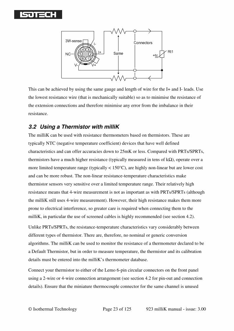
If you wish to make temporary connections to a 3-wire PRT using intermediate connectors
(typically required for calibrating 3-wire PRTs), then you must ensure that the resistance in
the extension connections to the I+ and I- wires is the same:
© Isothermal Technology Page 23 of 125 923 milliK manual - issue: 3.00
This can be achieved by using the same gauge and length of wire for the I+ and I- leads. Use
the lowest resistance wire (that is mechanically suitable) so as to minimise the resistance of
the extension connections and therefore minimise any error from the imbalance in their
resistance.
3.2 Using a Thermistor with milliK
The milliK can be used with resistance thermometers based on thermistors. These are
typically NTC (negative temperature coefficient) devices that have well defined
characteristics and can offer accuracies down to 25mK or less. Compared with PRTs/SPRTs,
thermistors have a much higher resistance (typically measured in tens of kΩ), operate over a
more limited temperature range (typically < 150°C), are highly non-linear but are lower cost
and can be more robust. The non-linear resistance-temperature characteristics make
thermistor sensors very sensitive over a limited temperature range. Their relatively high
resistance means that 4-wire measurement is not as important as with PRTs/SPRTs (although
the milliK still uses 4-wire measurement). However, their high resistance makes them more
prone to electrical interference, so greater care is required when connecting them to the
milliK, in particular the use of screened cables is highly recommended (see section 4.2).
Unlike PRTs/SPRTs, the resistance-temperature characteristics vary considerably between
different types of thermistor. There are, therefore, no nominal or generic conversion
algorithms. The milliK can be used to monitor the resistance of a thermometer declared to be
a Default Thermistor, but in order to measure temperature, the thermistor and its calibration
details must be entered into the milliK’s thermometer database.
Connect your thermistor to either of the Lemo 6-pin circular connectors on the front panel
using a 2-wire or 4-wire connection arrangement (see section 4.2 for pin-out and connection
details). Ensure that the miniature thermocouple connector for the same channel is unused
© Isothermal Technology Page 24 of 125 923 milliK manual - issue: 3.00
(since it is connected in parallel with the Lemo connector). Your milliK is supplied with two
Lemo connectors for you to use with thermistors. The part number for this connector is:
Lemo part number: FGG.1B.306.CLAD62Z
Additional connectors are readily available internationally from Farnell Electronics and can
be ordered via their website www.farnell.com (Farnell stock code 3817325).
Channels 1 and 2 are not isolated from each other, but are isolated from Channel 3 and from
the digital interfaces in order to optimise immunity to external noise sources.
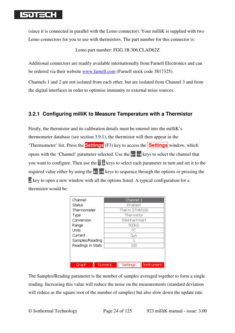
3.2.1 Configuring milliK to Measure Temperature with a Thermistor
Firstly, the thermistor and its calibration details must be entered into the milliK’s
thermometer database (see section 3.9.1), the thermistor will then appear in the
‘Thermometer’ list. Press the Settings (F3) key to access the Settings window, which
opens with the ‘Channel’ parameter selected. Use the ←←←← →→→→ keys to select the channel that
you want to configure. Then use the ↑↑↑↑ ↓↓↓↓ keys to select each parameter in turn and set it to the
required value either by using the ←←←← →→→→ keys to sequence through the options or pressing the
↵↵↵↵ key to open a new window with all the options listed. A typical configuration for a
thermistor would be:
The Samples/Reading parameter is the number of samples averaged together to form a single
reading. Increasing this value will reduce the noise on the measurements (standard deviation
will reduce as the square root of the number of samples) but also slow down the update rate.
© Isothermal Technology Page 25 of 125 923 milliK manual - issue: 3.00
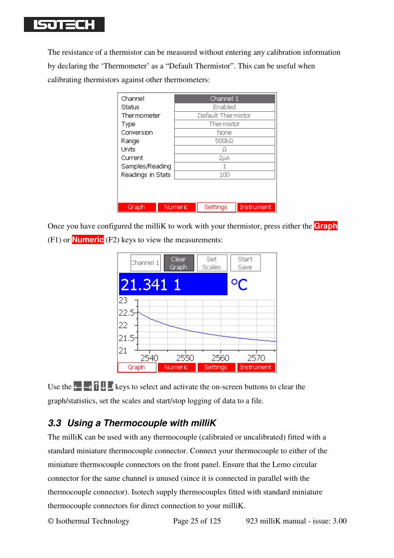
The resistance of a thermistor can be measured without entering any calibration information
by declaring the ‘Thermometer’ as a “Default Thermistor”. This can be useful when
calibrating thermistors against other thermometers:
Once you have configured the milliK to work with your thermistor, press either the Graph
(F1) or Numeric (F2) keys to view the measurements:
Use the ←←←← →→→→ ↑↑↑↑ ↓↓↓↓ ↵↵↵↵ keys to select and activate the on-screen buttons to clear the
graph/statistics, set the scales and start/stop logging of data to a file.
3.3 Using a Thermocouple with milliK
The milliK can be used with any thermocouple (calibrated or uncalibrated) fitted with a
standard miniature thermocouple connector. Connect your thermocouple to either of the
miniature thermocouple connectors on the front panel. Ensure that the Lemo circular
connector for the same channel is unused (since it is connected in parallel with the
thermocouple connector). Isotech supply thermocouples fitted with standard miniature
thermocouple connectors for direct connection to your milliK.
© Isothermal Technology Page 26 of 125 923 milliK manual - issue: 3.00
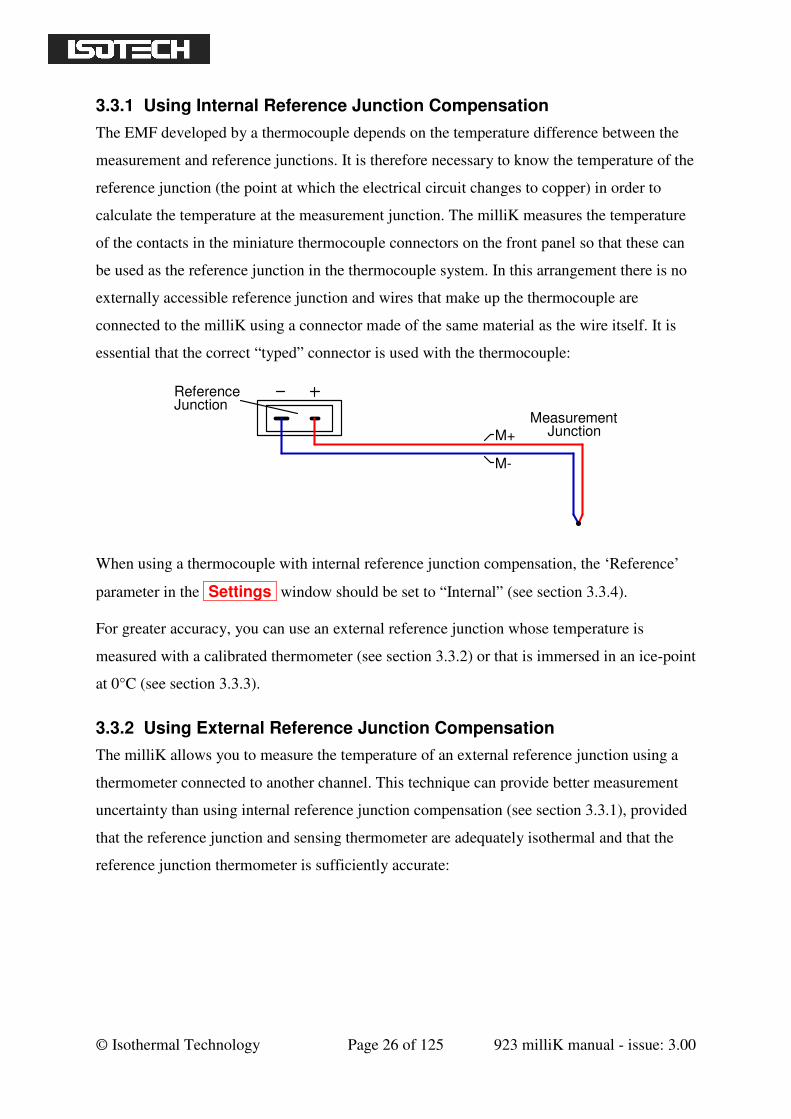
3.3.1 Using Internal Reference Junction Compensation
The EMF developed by a thermocouple depends on the temperature difference between the
measurement and reference junctions. It is therefore necessary to know the temperature of the
reference junction (the point at which the electrical circuit changes to copper) in order to
calculate the temperature at the measurement junction. The milliK measures the temperature
of the contacts in the miniature thermocouple connectors on the front panel so that these can
be used as the reference junction in the thermocouple system. In this arrangement there is no
externally accessible reference junction and wires that make up the thermocouple are
connected to the milliK using a connector made of the same material as the wire itself. It is
essential that the correct “typed” connector is used with the thermocouple:
Reference
MeasurementJunction
JunctionM+
M-
When using a thermocouple with internal reference junction compensation, the ‘Reference’
parameter in the Settings window should be set to “Internal” (see section 3.3.4).
For greater accuracy, you can use an external reference junction whose temperature is
measured with a calibrated thermometer (see section 3.3.2) or that is immersed in an ice-point
at 0°C (see section 3.3.3).
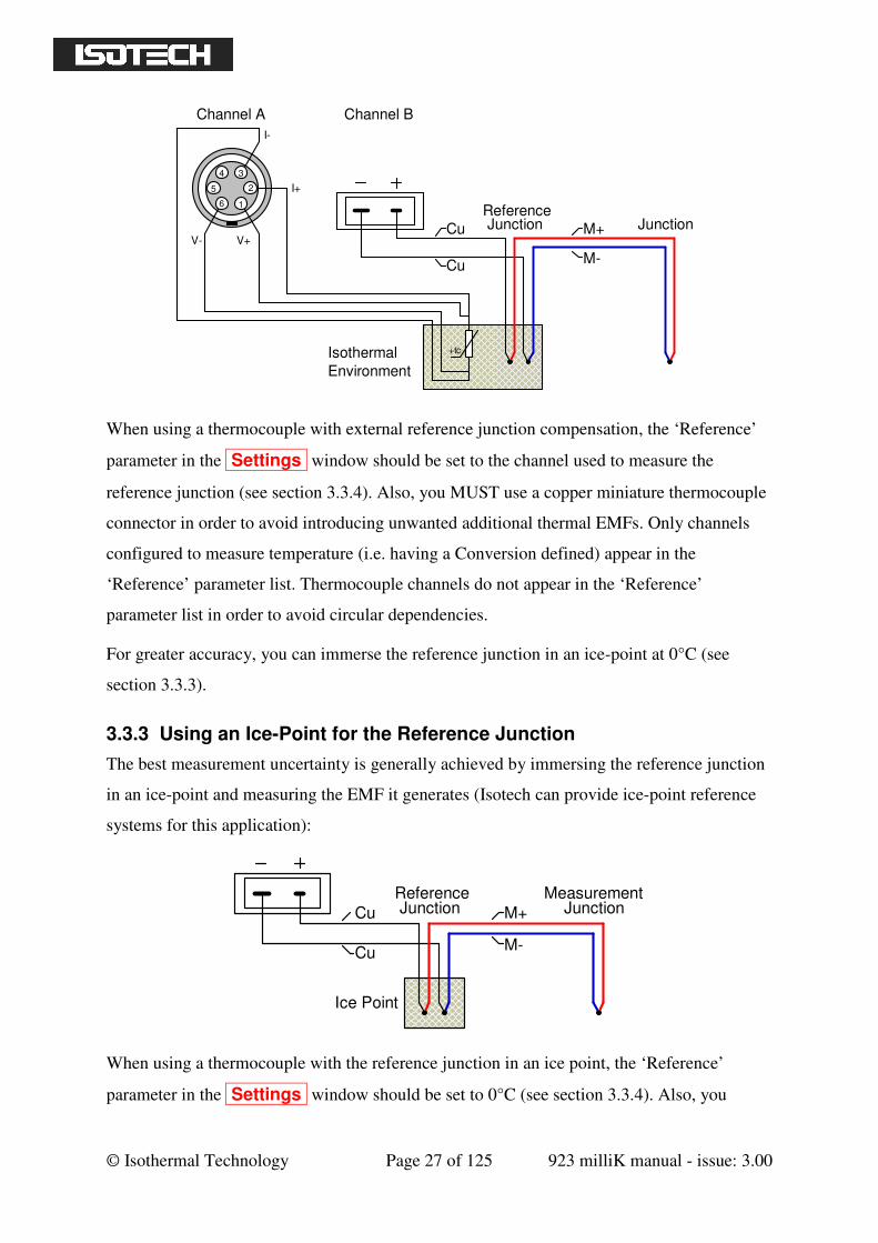
3.3.2 Using External Reference Junction Compensation
The milliK allows you to measure the temperature of an external reference junction using a
thermometer connected to another channel. This technique can provide better measurement
uncertainty than using internal reference junction compensation (see section 3.3.1), provided
that the reference junction and sensing thermometer are adequately isothermal and that the
reference junction thermometer is sufficiently accurate:
© Isothermal Technology Page 27 of 125 923 milliK manual - issue: 3.00
ReferenceJunction JunctionCu
Cu
M+
M-
+tc
4
5
6 1
2
I-
V+V-
3
I+
Isothermal
Environment
Channel A Channel B
When using a thermocouple with external reference junction compensation, the ‘Reference’
parameter in the Settings window should be set to the channel used to measure the
reference junction (see section 3.3.4). Also, you MUST use a copper miniature thermocouple
connector in order to avoid introducing unwanted additional thermal EMFs. Only channels
configured to measure temperature (i.e. having a Conversion defined) appear in the
‘Reference’ parameter list. Thermocouple channels do not appear in the ‘Reference’
parameter list in order to avoid circular dependencies.
For greater accuracy, you can immerse the reference junction in an ice-point at 0°C (see
section 3.3.3).
3.3.3 Using an Ice-Point for the Reference Junction
The best measurement uncertainty is generally achieved by immersing the reference junction
in an ice-point and measuring the EMF it generates (Isotech can provide ice-point reference
systems for this application):
Reference MeasurementJunction Junction
Ice Point
Cu
Cu
M+
M-
When using a thermocouple with the reference junction in an ice point, the ‘Reference’
parameter in the Settings window should be set to 0°C (see section 3.3.4). Also, you
© Isothermal Technology Page 28 of 125 923 milliK manual - issue: 3.00
MUST use a copper miniature thermocouple connector in order to avoid introducing
unwanted additional thermal EMFs.
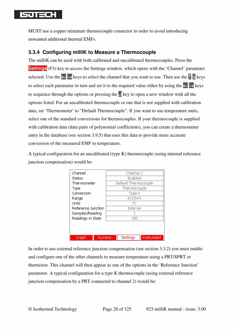
3.3.4 Configuring milliK to Measure a Thermocouple
The milliK can be used with both calibrated and uncalibrated thermocouples. Press the
Settings (F3) key to access the Settings window, which opens with the ‘Channel’ parameter
selected. Use the ←←←← →→→→ keys to select the channel that you want to use. Then use the ↑↑↑↑ ↓↓↓↓ keys
to select each parameter in turn and set it to the required value either by using the ←←←← →→→→ keys
to sequence through the options or pressing the ↵↵↵↵ key to open a new window with all the
options listed. For an uncalibrated thermocouple or one that is not supplied with calibration
data, set ‘Thermometer’ to “Default Thermocouple”. If you want to use temperature units,
select one of the standard conversions for thermocouples. If your thermocouple is supplied
with calibration data (data pairs of polynomial coefficients), you can create a thermometer
entry in the database (see section 3.9.5) that uses this data to provide more accurate
conversion of the measured EMF to temperature.
A typical configuration for an uncalibrated (type K) thermocouple (using internal reference
junction compensation) would be:
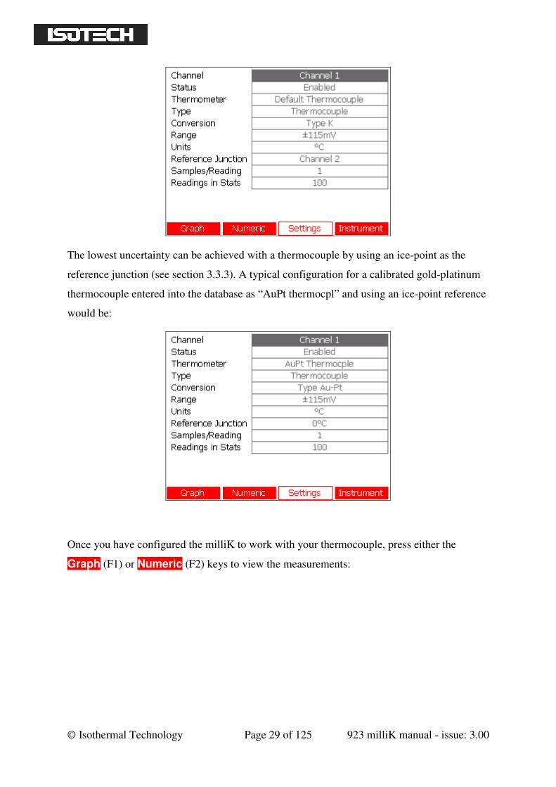
In order to use external reference junction compensation (see section 3.3.2) you must enable
and configure one of the other channels to measure temperature using a PRT/SPRT or
thermistor. This channel will then appear as one of the options in the ‘Reference Junction’
parameter. A typical configuration for a type K thermocouple (using external reference
junction compensation by a PRT connected to channel 2) would be:
© Isothermal Technology Page 29 of 125 923 milliK manual - issue: 3.00
The lowest uncertainty can be achieved with a thermocouple by using an ice-point as the
reference junction (see section 3.3.3). A typical configuration for a calibrated gold-platinum
thermocouple entered into the database as “AuPt thermocpl” and using an ice-point reference
would be:
Once you have configured the milliK to work with your thermocouple, press either the
Graph (F1) or Numeric (F2) keys to view the measurements:
© Isothermal Technology Page 30 of 125 923 milliK manual - issue: 3.00
Use the ←←←← →→→→ ↑↑↑↑ ↓↓↓↓ ↵↵↵↵ keys to select and activate the on-screen buttons, which select the
channel, clear the graph (‘Graph’ window), clear the statistics (‘Numeric’ window), set the
scales and start/stop logging of data to a file.
3.4 Using a 4-20mA Transmitter with milliK
The milliK can be used with 4-20mA temperature transmitters by using the 4mm sockets on
the rear of the milliK (designated Channel 3). The centre 4mm socket is the current sense
input to the milliK, the other 4mm sockets are 0V and a +24V supply. Connect the
transmitter between the appropriate 4mm sockets depending on whether it is self-powered or
loop-powered (suitable for a 24V loop supply):
4-20mA 4-20mA
Self-Powered Transmitter Loop-Powered Transmitter
The 4-20mA system and 24V supply are isolated from both the measurement system of
Channels 1 and 2 and from the digital interfaces in order to optimise immunity to external
(common-mode) noise sources.
© Isothermal Technology Page 31 of 125 923 milliK manual - issue: 3.00
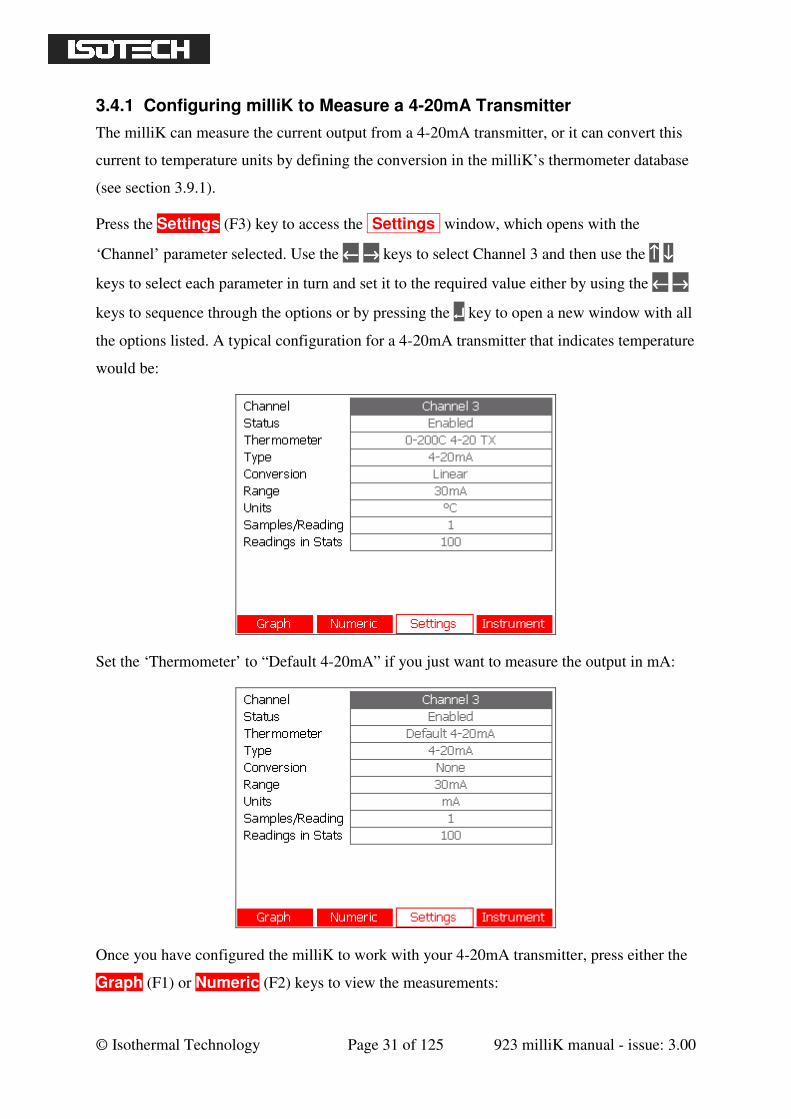
3.4.1 Configuring milliK to Measure a 4-20mA Transmitter
The milliK can measure the current output from a 4-20mA transmitter, or it can convert this
current to temperature units by defining the conversion in the milliK’s thermometer database
(see section 3.9.1).
Press the Settings (F3) key to access the Settings window, which opens with the
‘Channel’ parameter selected. Use the ←←←← →→→→ keys to select Channel 3 and then use the ↑↑↑↑ ↓↓↓↓
keys to select each parameter in turn and set it to the required value either by using the ←←←← →→→→
keys to sequence through the options or by pressing the ↵↵↵↵ key to open a new window with all
the options listed. A typical configuration for a 4-20mA transmitter that indicates temperature
would be:
Set the ‘Thermometer’ to “Default 4-20mA” if you just want to measure the output in mA:
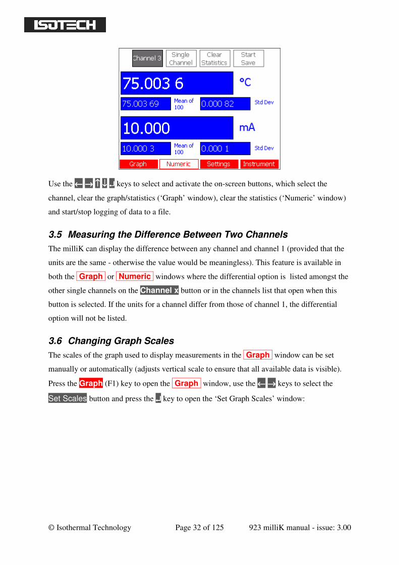
Once you have configured the milliK to work with your 4-20mA transmitter, press either the
Graph (F1) or Numeric (F2) keys to view the measurements:
© Isothermal Technology Page 32 of 125 923 milliK manual - issue: 3.00
Use the ←←←← →→→→ ↑↑↑↑ ↓↓↓↓ ↵↵↵↵ keys to select and activate the on-screen buttons, which select the
channel, clear the graph/statistics (‘Graph’ window), clear the statistics (‘Numeric’ window)
and start/stop logging of data to a file.
3.5 Measuring the Difference Between Two Channels
The milliK can display the difference between any channel and channel 1 (provided that the
units are the same - otherwise the value would be meaningless). This feature is available in
both the Graph or Numeric windows where the differential option is listed amongst the
other single channels on the Channel x button or in the channels list that open when this
button is selected. If the units for a channel differ from those of channel 1, the differential
option will not be listed.
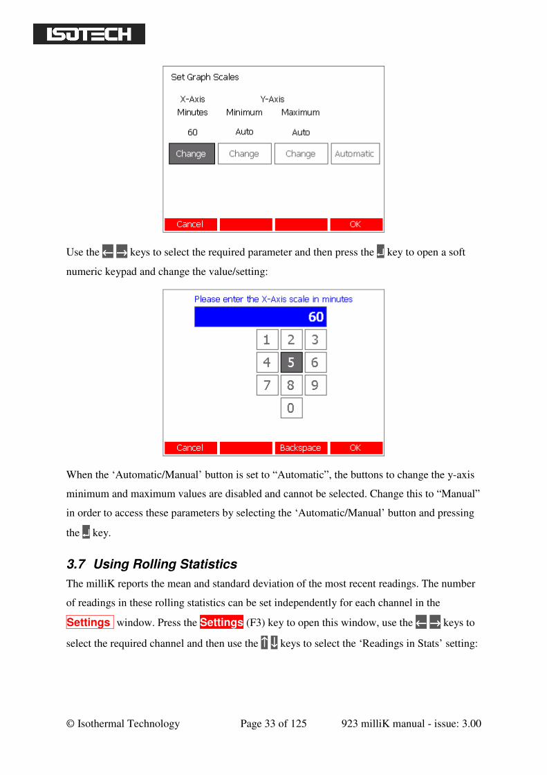
3.6 Changing Graph Scales
The scales of the graph used to display measurements in the Graph window can be set
manually or automatically (adjusts vertical scale to ensure that all available data is visible).
Press the Graph (F1) key to open the Graph window, use the ←←←← →→→→ keys to select the
Set Scales button and press the ↵↵↵↵ key to open the ‘Set Graph Scales’ window:
© Isothermal Technology Page 33 of 125 923 milliK manual - issue: 3.00
Use the ←←←← →→→→ keys to select the required parameter and then press the ↵↵↵↵ key to open a soft
numeric keypad and change the value/setting:
When the ‘Automatic/Manual’ button is set to “Automatic”, the buttons to change the y-axis
minimum and maximum values are disabled and cannot be selected. Change this to “Manual”
in order to access these parameters by selecting the ‘Automatic/Manual’ button and pressing
the ↵↵↵↵ key.
3.7 Using Rolling Statistics
The milliK reports the mean and standard deviation of the most recent readings. The number
of readings in these rolling statistics can be set independently for each channel in the
Settings window. Press the Settings (F3) key to open this window, use the ←←←← →→→→ keys to
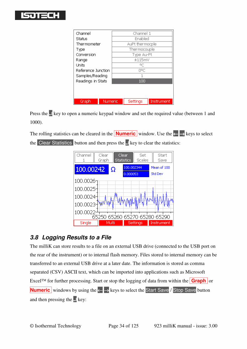
select the required channel and then use the ↑↑↑↑ ↓↓↓↓ keys to select the ‘Readings in Stats’ setting:
© Isothermal Technology Page 34 of 125 923 milliK manual - issue: 3.00
Press the ↵↵↵↵ key to open a numeric keypad window and set the required value (between 1 and
1000).
The rolling statistics can be cleared in the Numeric window. Use the ←←←← →→→→ keys to select
the Clear Statistics button and then press the ↵↵↵↵ key to clear the statistics:
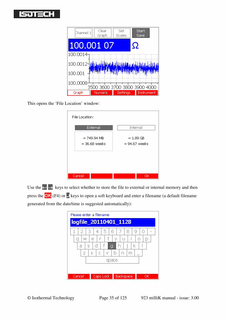
3.8 Logging Results to a File
The milliK can store results to a file on an external USB drive (connected to the USB port on
the rear of the instrument) or to internal flash memory. Files stored to internal memory can be
transferred to an external USB drive at a later date. The information is stored as comma
separated (CSV) ASCII text, which can be imported into applications such as Microsoft
Excel™ for further processing. Start or stop the logging of data from within the Graph or
Numeric windows by using the ←←←← →→→→ keys to select the Start Save / Stop Save button
and then pressing the ↵↵↵↵ key:
© Isothermal Technology Page 35 of 125 923 milliK manual - issue: 3.00
This opens the ‘File Location’ window:
Use the ←←←← →→→→ keys to select whether to store the file to external or internal memory and then
press the OK (F4) or ↵↵↵↵ keys to open a soft keyboard and enter a filename (a default filename
generated from the date/time is suggested automatically):
© Isothermal Technology Page 36 of 125 923 milliK manual - issue: 3.00
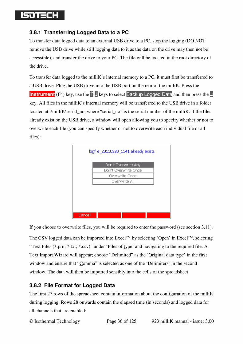
3.8.1 Transferring Logged Data to a PC
To transfer data logged data to an external USB drive to a PC, stop the logging (DO NOT
remove the USB drive while still logging data to it as the data on the drive may then not be
accessible), and transfer the drive to your PC. The file will be located in the root directory of
the drive.
To transfer data logged to the milliK’s internal memory to a PC, it must first be transferred to
a USB drive. Plug the USB drive into the USB port on the rear of the milliK. Press the
Instrument (F4) key, use the ↑↑↑↑ ↓↓↓↓ keys to select Backup Logged Data and then press the ↵↵↵↵
key. All files in the milliK’s internal memory will be transferred to the USB drive in a folder
located at :\milliK\serial_no, where “serial_no” is the serial number of the milliK. If the files
already exist on the USB drive, a window will open allowing you to specify whether or not to
overwrite each file (you can specify whether or not to overwrite each individual file or all
files):
If you choose to overwrite files, you will be required to enter the password (see section 3.11).
The CSV logged data can be imported into Excel™ by selecting ‘Open’ in Excel™, selecting
“Text Files (*.prn; *.txt; *.csv)” under ‘Files of type’ and navigating to the required file. A
Text Import Wizard will appear; choose “Delimited” as the ‘Original data type’ in the first
window and ensure that “Comma” is selected as one of the ‘Delimiters’ in the second
window. The data will then be imported sensibly into the cells of the spreadsheet.
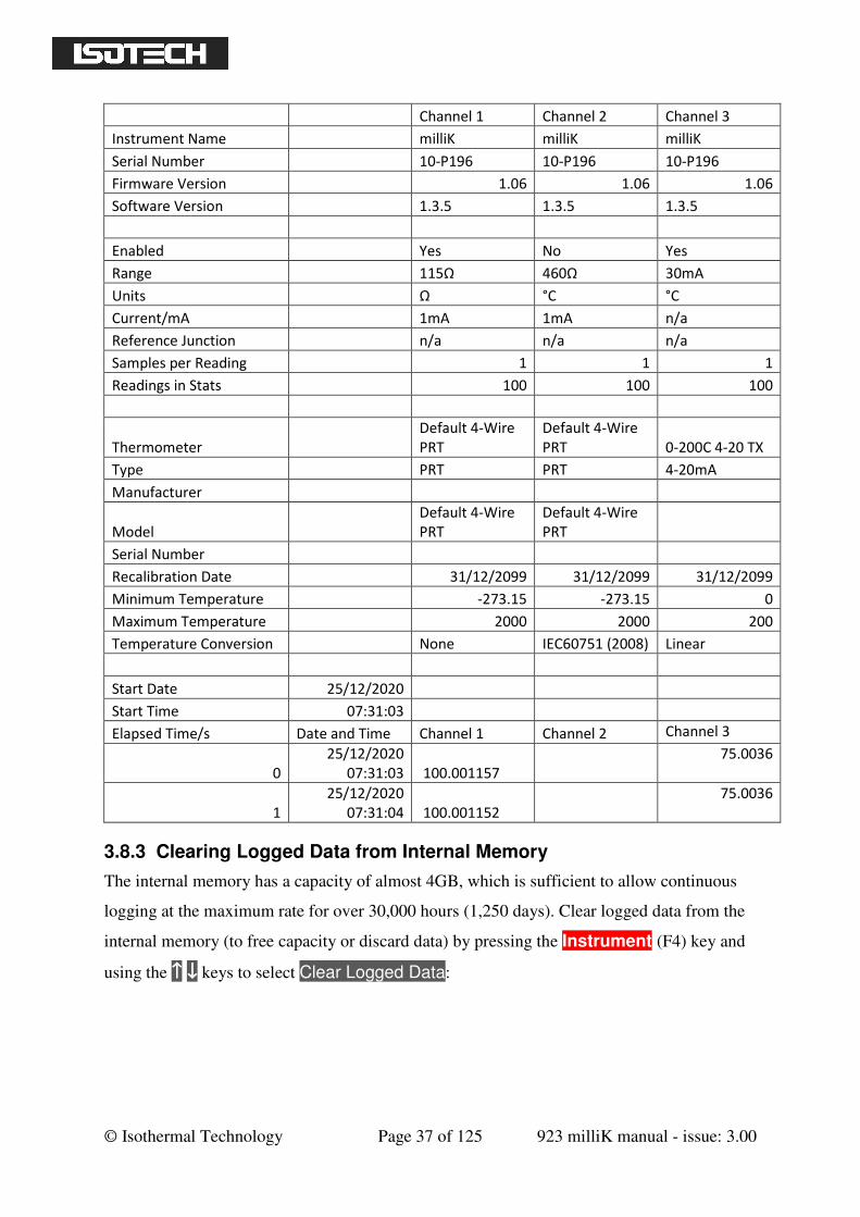
3.8.2 File Format for Logged Data
The first 27 rows of the spreadsheet contain information about the configuration of the milliK
during logging. Rows 28 onwards contain the elapsed time (in seconds) and logged data for
all channels that are enabled:
© Isothermal Technology Page 37 of 125 923 milliK manual - issue: 3.00
Channel 1 Channel 2 Channel 3
Instrument Name milliK milliK milliK
Serial Number 10-P196 10-P196 10-P196
Firmware Version 1.06 1.06 1.06
Software Version 1.3.5 1.3.5 1.3.5
Enabled Yes No Yes
Range 115Ω 460Ω 30mA
Units Ω °C °C
Current/mA 1mA 1mA n/a
Reference Junction n/a n/a n/a
Samples per Reading 1 1 1
Readings in Stats 100 100 100
Thermometer
Default 4-Wire
PRT
Default 4-Wire
PRT 0-200C 4-20 TX
Type PRT PRT 4-20mA
Manufacturer
Model
Default 4-Wire
PRT
Default 4-Wire
PRT
Serial Number
Recalibration Date 31/12/2099 31/12/2099 31/12/2099
Minimum Temperature -273.15 -273.15 0
Maximum Temperature 2000 2000 200
Temperature Conversion None IEC60751 (2008) Linear
Start Date 25/12/2020
Start Time 07:31:03
Elapsed Time/s Date and Time Channel 1 Channel 2 Channel 3
0
25/12/2020
07:31:03 100.001157
75.0036
1
25/12/2020
07:31:04 100.001152
75.0036
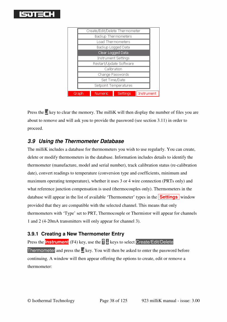
3.8.3 Clearing Logged Data from Internal Memory
The internal memory has a capacity of almost 4GB, which is sufficient to allow continuous
logging at the maximum rate for over 30,000 hours (1,250 days). Clear logged data from the
internal memory (to free capacity or discard data) by pressing the Instrument (F4) key and
using the ↑↑↑↑ ↓↓↓↓ keys to select Clear Logged Data:
© Isothermal Technology Page 38 of 125 923 milliK manual - issue: 3.00
Press the ↵↵↵↵ key to clear the memory. The milliK will then display the number of files you are
about to remove and will ask you to provide the password (see section 3.11) in order to
proceed.
3.9 Using the Thermometer Database
The milliK includes a database for thermometers you wish to use regularly. You can create,
delete or modify thermometers in the database. Information includes details to identify the
thermometer (manufacture, model and serial number), track calibration status (re-calibration
date), convert readings to temperature (conversion type and coefficients, minimum and
maximum operating temperature), whether it uses 3 or 4 wire connection (PRTs only) and
what reference junction compensation is used (thermocouples only). Thermometers in the
database will appear in the list of available ‘Thermometer’ types in the Settings window
provided that they are compatible with the selected channel. This means that only
thermometers with ‘Type’ set to PRT, Thermocouple or Thermistor will appear for channels
1 and 2 (4-20mA transmitters will only appear for channel 3).
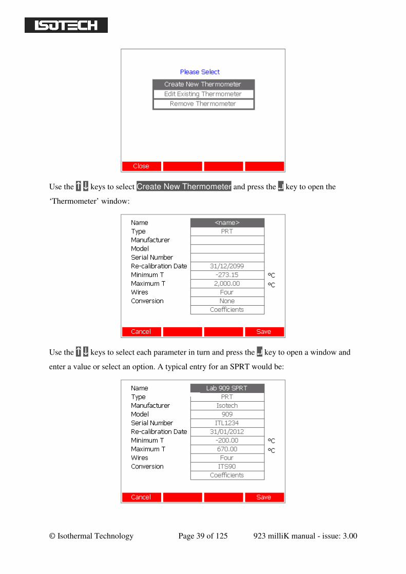
3.9.1 Creating a New Thermometer Entry
Press the Instrument (F4) key, use the ↑↑↑↑ ↓↓↓↓ keys to select Create/Edit/Delete
Thermometer and press the ↵↵↵↵ key. You will then be asked to enter the password before
continuing. A window will then appear offering the options to create, edit or remove a
thermometer:
© Isothermal Technology Page 39 of 125 923 milliK manual - issue: 3.00
Use the ↑↑↑↑ ↓↓↓↓ keys to select Create New Thermometer and press the ↵↵↵↵ key to open the
‘Thermometer’ window:
Use the ↑↑↑↑ ↓↓↓↓ keys to select each parameter in turn and press the ↵↵↵↵ key to open a window and
enter a value or select an option. A typical entry for an SPRT would be:
© Isothermal Technology Page 40 of 125 923 milliK manual - issue: 3.00
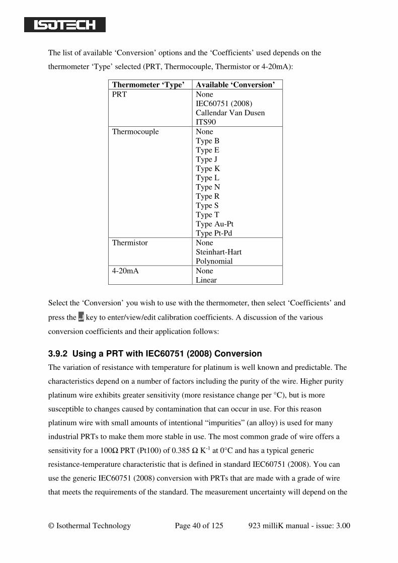
The list of available ‘Conversion’ options and the ‘Coefficients’ used depends on the
thermometer ‘Type’ selected (PRT, Thermocouple, Thermistor or 4-20mA):
Thermometer ‘Type’ Available ‘Conversion’
PRT None
IEC60751 (2008)
Callendar Van Dusen
ITS90
Thermocouple None
Type B
Type E
Type J
Type K
Type L
Type N
Type R
Type S
Type T
Type Au-Pt
Type Pt-Pd
Thermistor None
Steinhart-Hart
Polynomial
4-20mA None
Linear
Select the ‘Conversion’ you wish to use with the thermometer, then select ‘Coefficients’ and
press the ↵↵↵↵ key to enter/view/edit calibration coefficients. A discussion of the various
conversion coefficients and their application follows:
3.9.2 Using a PRT with IEC60751 (2008) Conversion
The variation of resistance with temperature for platinum is well known and predictable. The
characteristics depend on a number of factors including the purity of the wire. Higher purity
platinum wire exhibits greater sensitivity (more resistance change per °C), but is more
susceptible to changes caused by contamination that can occur in use. For this reason
platinum wire with small amounts of intentional “impurities” (an alloy) is used for many
industrial PRTs to make them more stable in use. The most common grade of wire offers a
sensitivity for a 100Ω PRT (Pt100) of 0.385 Ω K-1 at 0°C and has a typical generic
resistance-temperature characteristic that is defined in standard IEC60751 (2008). You can
use the generic IEC60751 (2008) conversion with PRTs that are made with a grade of wire
that meets the requirements of the standard. The measurement uncertainty will depend on the
© Isothermal Technology Page 41 of 125 923 milliK manual - issue: 3.00
class of thermometer and its temperature and can vary from ±0.15°C (Class A Pt100 at 0°C)
to ±4.6°C (Class B Pt100 at 850°C).
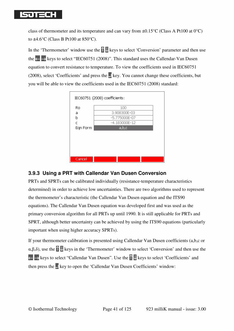
In the ‘Thermometer’ window use the ↑↑↑↑ ↓↓↓↓ keys to select ‘Conversion’ parameter and then use
the ←←←← →→→→ keys to select “IEC60751 (2008)”. This standard uses the Callendar-Van Dusen
equation to convert resistance to temperature. To view the coefficients used in IEC60751
(2008), select ‘Coefficients’ and press the ↵↵↵↵ key. You cannot change these coefficients, but
you will be able to view the coefficients used in the IEC60751 (2008) standard:
3.9.3 Using a PRT with Callendar Van Dusen Conversion
PRTs and SPRTs can be calibrated individually (resistance-temperature characteristics
determined) in order to achieve low uncertainties. There are two algorithms used to represent
the thermometer’s characteristic (the Callendar Van Dusen equation and the ITS90
equations). The Callendar Van Dusen equation was developed first and was used as the
primary conversion algorithm for all PRTs up until 1990. It is still applicable for PRTs and
SPRT, although better uncertainty can be achieved by using the ITS90 equations (particularly
important when using higher accuracy SPRTs).
If your thermometer calibration is presented using Callendar Van Dusen coefficients (a,b,c or
α,β,δ), use the ↑↑↑↑ ↓↓↓↓ keys in the ‘Thermometer’ window to select ‘Conversion’ and then use the
←←←← →→→→ keys to select “Callendar Van Dusen”. Use the ↑↑↑↑ ↓↓↓↓ keys to select ‘Coefficients’ and
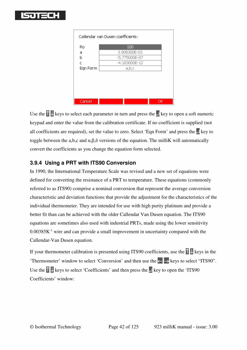
then press the ↵↵↵↵ key to open the ‘Callendar Van Dusen Coefficients’ window:
© Isothermal Technology Page 42 of 125 923 milliK manual - issue: 3.00
Use the ↑↑↑↑ ↓↓↓↓ keys to select each parameter in turn and press the ↵↵↵↵ key to open a soft numeric
keypad and enter the value from the calibration certificate. If no coefficient is supplied (not
all coefficients are required), set the value to zero. Select ‘Eqn Form’ and press the ↵↵↵↵ key to
toggle between the a,b,c and α,β,δ versions of the equation. The milliK will automatically
convert the coefficients as you change the equation form selected.
3.9.4 Using a PRT with ITS90 Conversion
In 1990, the International Temperature Scale was revised and a new set of equations were
defined for converting the resistance of a PRT to temperature. These equations (commonly
referred to as ITS90) comprise a nominal conversion that represent the average conversion
characteristic and deviation functions that provide the adjustment for the characteristics of the
individual thermometer. They are intended for use with high purity platinum and provide a
better fit than can be achieved with the older Callendar Van Dusen equation. The ITS90
equations are sometimes also used with industrial PRTs, made using the lower sensitivity
0.00385K-1 wire and can provide a small improvement in uncertainty compared with the
Callendar-Van Dusen equation.
If your thermometer calibration is presented using ITS90 coefficients, use the ↑↑↑↑ ↓↓↓↓ keys in the
‘Thermometer’ window to select ‘Conversion’ and then use the ←←←← →→→→ keys to select “ITS90”.
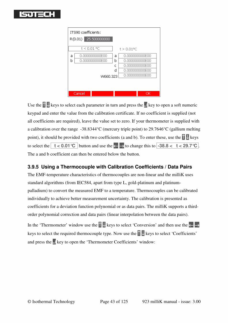
Use the ↑↑↑↑ ↓↓↓↓ keys to select ‘Coefficients’ and then press the ↵↵↵↵ key to open the ‘ITS90
Coefficients’ window:
© Isothermal Technology Page 43 of 125 923 milliK manual - issue: 3.00
Use the ↑↑↑↑ ↓↓↓↓ keys to select each parameter in turn and press the ↵↵↵↵ key to open a soft numeric
keypad and enter the value from the calibration certificate. If no coefficient is supplied (not
all coefficients are required), leave the value set to zero. If your thermometer is supplied with
a calibration over the range -38.8344°C (mercury triple point) to 29.7646°C (gallium melting
point), it should be provided with two coefficients (a and b). To enter these, use the ↑↑↑↑ ↓↓↓↓ keys
to select the t < 0.01°C button and use the ←←←← →→→→ to change this to -38.8 < t < 29.7°C .
The a and b coefficient can then be entered below the button.
3.9.5 Using a Thermocouple with Calibration Coefficients / Data Pairs
The EMF-temperature characteristics of thermocouples are non-linear and the milliK uses
standard algorithms (from IEC584, apart from type L, gold-platinum and platinum-
palladium) to convert the measured EMF to a temperature. Thermocouples can be calibrated
individually to achieve better measurement uncertainty. The calibration is presented as
coefficients for a deviation function polynomial or as data pairs. The milliK supports a third-
order polynomial correction and data pairs (linear interpolation between the data pairs).
In the ‘Thermometer’ window use the ↑↑↑↑ ↓↓↓↓ keys to select ‘Conversion’ and then use the ←←←← →→→→
keys to select the required thermocouple type. Now use the ↑↑↑↑ ↓↓↓↓ keys to select ‘Coefficients’
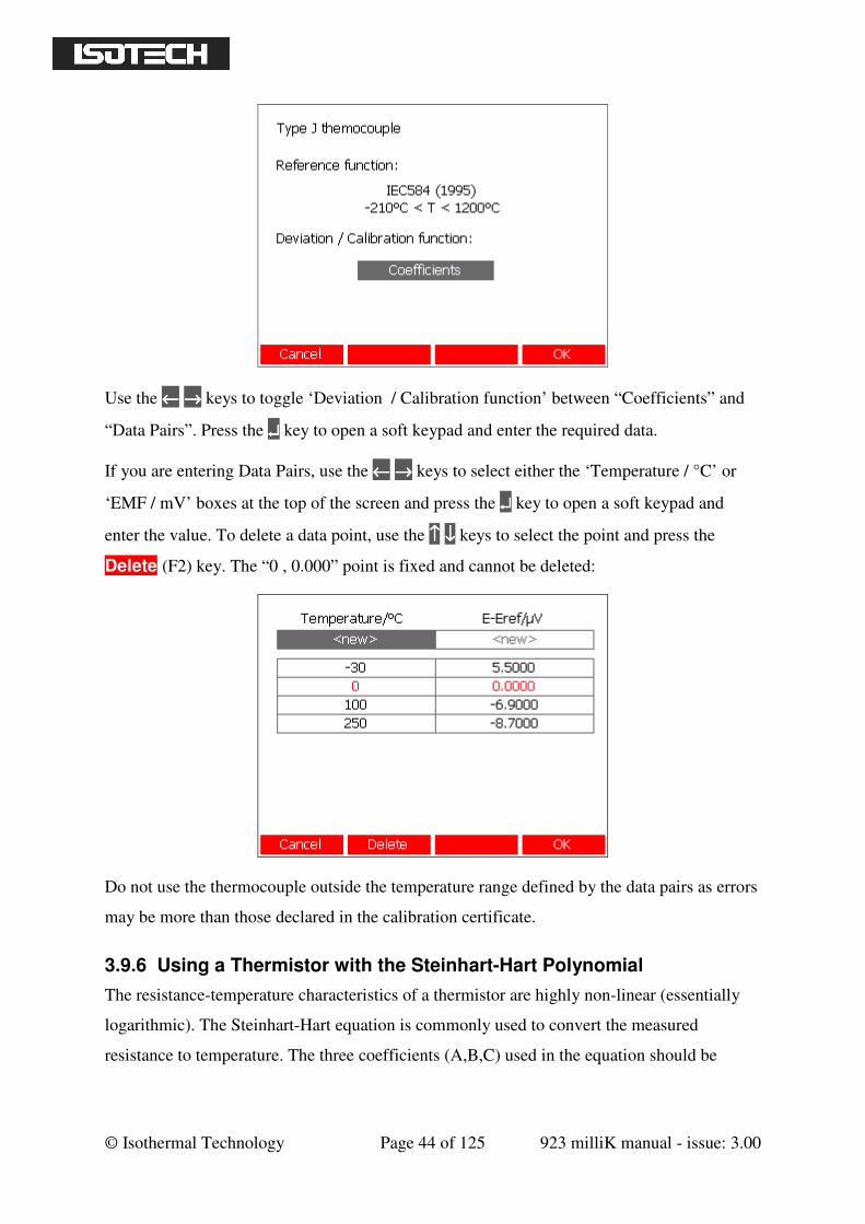
and press the ↵↵↵↵ key to open the ‘Thermometer Coefficients’ window:
© Isothermal Technology Page 44 of 125 923 milliK manual - issue: 3.00
Use the ←←←← →→→→ keys to toggle ‘Deviation / Calibration function’ between “Coefficients” and
“Data Pairs”. Press the ↵↵↵↵ key to open a soft keypad and enter the required data.
If you are entering Data Pairs, use the ←←←← →→→→ keys to select either the ‘Temperature / °C’ or
‘EMF / mV’ boxes at the top of the screen and press the ↵↵↵↵ key to open a soft keypad and
enter the value. To delete a data point, use the ↑↑↑↑ ↓↓↓↓ keys to select the point and press the
Delete (F2) key. The “0 , 0.000” point is fixed and cannot be deleted:
Do not use the thermocouple outside the temperature range defined by the data pairs as errors
may be more than those declared in the calibration certificate.
3.9.6 Using a Thermistor with the Steinhart-Hart Polynomial
The resistance-temperature characteristics of a thermistor are highly non-linear (essentially
logarithmic). The Steinhart-Hart equation is commonly used to convert the measured
resistance to temperature. The three coefficients (A,B,C) used in the equation should be
© Isothermal Technology Page 45 of 125 923 milliK manual - issue: 3.00
specified for the thermometer you are using (there is no generic characteristic for
thermistors).
Use the ↑↑↑↑ ↓↓↓↓ keys in the ‘Thermometer’ window to select ‘Conversion’ and then use the ←←←← →→→→
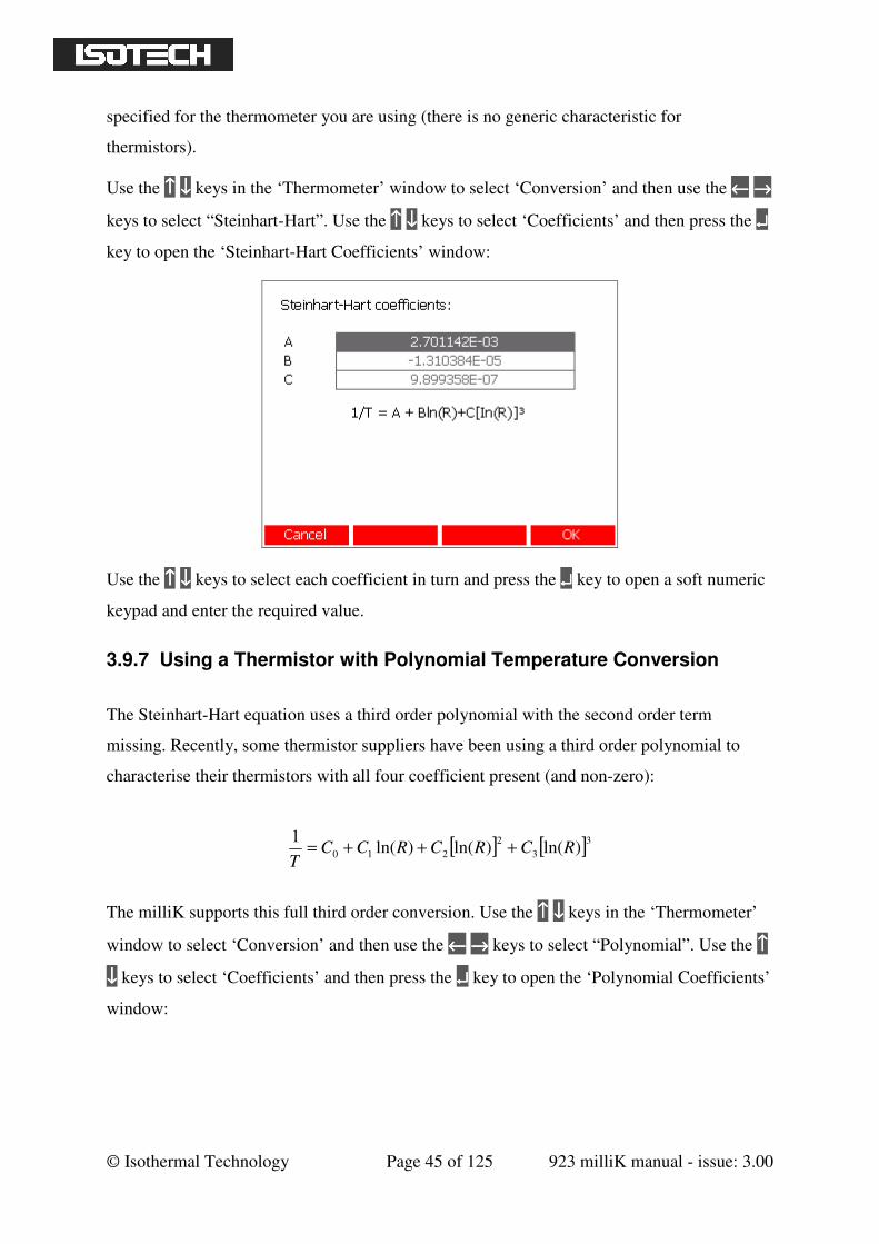
keys to select “Steinhart-Hart”. Use the ↑↑↑↑ ↓↓↓↓ keys to select ‘Coefficients’ and then press the ↵↵↵↵
key to open the ‘Steinhart-Hart Coefficients’ window:
Use the ↑↑↑↑ ↓↓↓↓ keys to select each coefficient in turn and press the ↵↵↵↵ key to open a soft numeric
keypad and enter the required value.
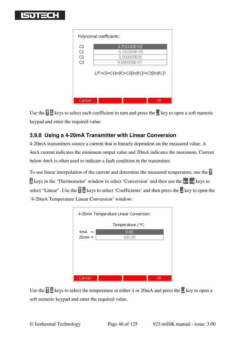
3.9.7 Using a Thermistor with Polynomial Temperature Conversion
The Steinhart-Hart equation uses a third order polynomial with the second order term
missing. Recently, some thermistor suppliers have been using a third order polynomial to
characterise their thermistors with all four coefficient present (and non-zero):
[ ] [ ]3
3
2
210 )ln()ln()ln(1
RCRCRCCT
+++=
The milliK supports this full third order conversion. Use the ↑↑↑↑ ↓↓↓↓ keys in the ‘Thermometer’
window to select ‘Conversion’ and then use the ←←←← →→→→ keys to select “Polynomial”. Use the ↑↑↑↑
↓↓↓↓ keys to select ‘Coefficients’ and then press the ↵↵↵↵ key to open the ‘Polynomial Coefficients’
window:
© Isothermal Technology Page 46 of 125 923 milliK manual - issue: 3.00
Use the ↑↑↑↑ ↓↓↓↓ keys to select each coefficient in turn and press the ↵↵↵↵ key to open a soft numeric
keypad and enter the required value.
3.9.8 Using a 4-20mA Transmitter with Linear Conversion
4-20mA transmitters source a current that is linearly dependent on the measured value. A
4mA current indicates the minimum output value and 20mA indicates the maximum. Current
below 4mA is often used to indicate a fault condition in the transmitter.
To use linear interpolation of the current and determine the measured temperature, use the ↑↑↑↑
↓↓↓↓ keys in the ‘Thermometer’ window to select ‘Conversion’ and then use the ←←←← →→→→ keys to
select “Linear”. Use the ↑↑↑↑ ↓↓↓↓ keys to select ‘Coefficients’ and then press the ↵↵↵↵ key to open the
‘4-20mA Temperature Linear Conversion’ window:
Use the ↑↑↑↑ ↓↓↓↓ keys to select the temperature at either 4 or 20mA and press the ↵↵↵↵ key to open a
soft numeric keypad and enter the required value.
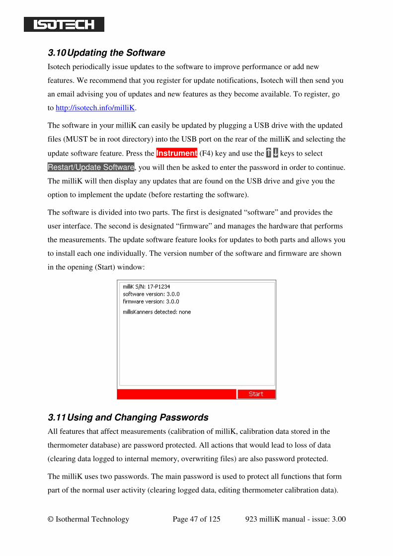
© Isothermal Technology Page 47 of 125 923 milliK manual - issue: 3.00
3.10 Updating the Software
Isotech periodically issue updates to the software to improve performance or add new
features. We recommend that you register for update notifications, Isotech will then send you
an email advising you of updates and new features as they become available. To register, go
to http://isotech.info/milliK.
The software in your milliK can easily be updated by plugging a USB drive with the updated
files (MUST be in root directory) into the USB port on the rear of the milliK and selecting the
update software feature. Press the Instrument (F4) key and use the ↑↑↑↑ ↓↓↓↓ keys to select
Restart/Update Software, you will then be asked to enter the password in order to continue.
The milliK will then display any updates that are found on the USB drive and give you the
option to implement the update (before restarting the software).
The software is divided into two parts. The first is designated “software” and provides the
user interface. The second is designated “firmware” and manages the hardware that performs
the measurements. The update software feature looks for updates to both parts and allows you
to install each one individually. The version number of the software and firmware are shown
in the opening (Start) window:
3.11 Using and Changing Passwords
All features that affect measurements (calibration of milliK, calibration data stored in the
thermometer database) are password protected. All actions that would lead to loss of data
(clearing data logged to internal memory, overwriting files) are also password protected.
The milliK uses two passwords. The main password is used to protect all functions that form
part of the normal user activity (clearing logged data, editing thermometer calibration data).
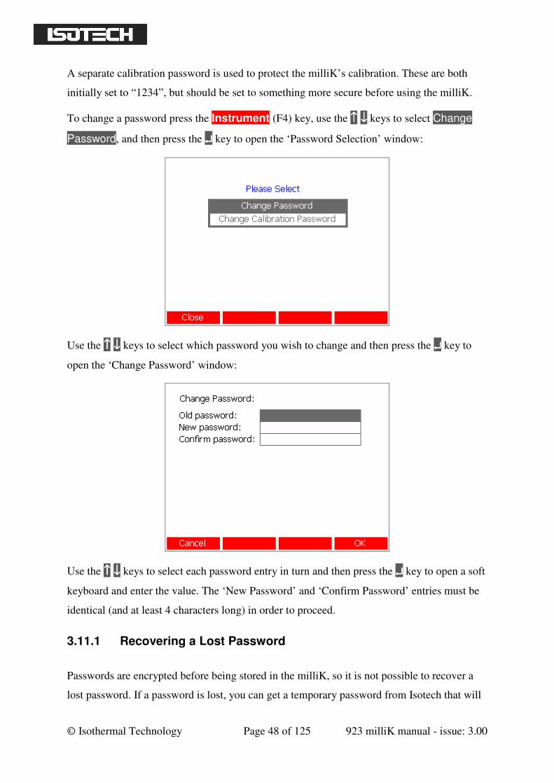
© Isothermal Technology Page 48 of 125 923 milliK manual - issue: 3.00
A separate calibration password is used to protect the milliK’s calibration. These are both
initially set to “1234”, but should be set to something more secure before using the milliK.
To change a password press the Instrument (F4) key, use the ↑↑↑↑ ↓↓↓↓ keys to select Change
Password, and then press the ↵↵↵↵ key to open the ‘Password Selection’ window:
Use the ↑↑↑↑ ↓↓↓↓ keys to select which password you wish to change and then press the ↵↵↵↵ key to
open the ‘Change Password’ window:
Use the ↑↑↑↑ ↓↓↓↓ keys to select each password entry in turn and then press the ↵↵↵↵ key to open a soft
keyboard and enter the value. The ‘New Password’ and ‘Confirm Password’ entries must be
identical (and at least 4 characters long) in order to proceed.
3.11.1 Recovering a Lost Password
Passwords are encrypted before being stored in the milliK, so it is not possible to recover a
lost password. If a password is lost, you can get a temporary password from Isotech that will
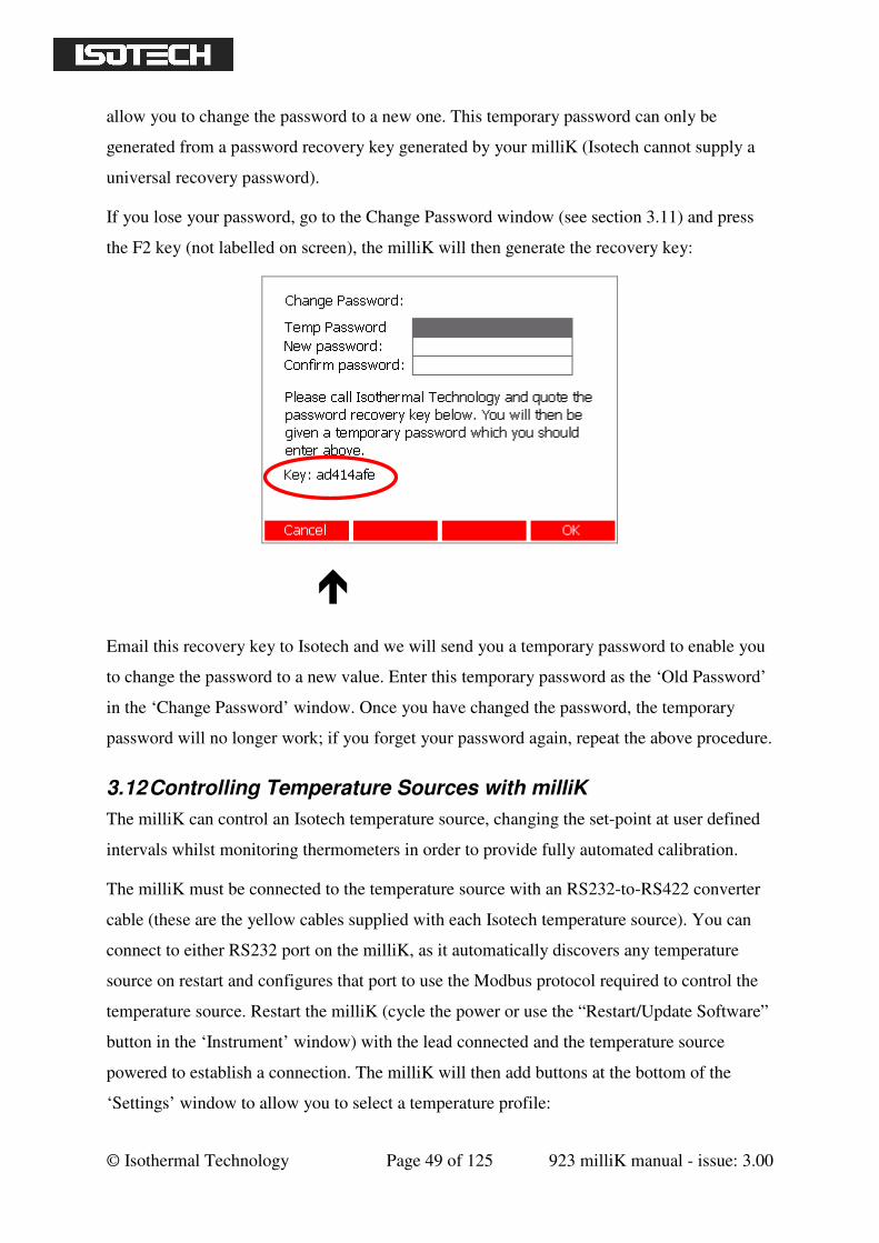
© Isothermal Technology Page 49 of 125 923 milliK manual - issue: 3.00
allow you to change the password to a new one. This temporary password can only be
generated from a password recovery key generated by your milliK (Isotech cannot supply a
universal recovery password).
If you lose your password, go to the Change Password window (see section 3.11) and press
the F2 key (not labelled on screen), the milliK will then generate the recovery key:
Email this recovery key to Isotech and we will send you a temporary password to enable you
to change the password to a new value. Enter this temporary password as the ‘Old Password’
in the ‘Change Password’ window. Once you have changed the password, the temporary
password will no longer work; if you forget your password again, repeat the above procedure.
3.12 Controlling Temperature Sources with milliK
The milliK can control an Isotech temperature source, changing the set-point at user defined
intervals whilst monitoring thermometers in order to provide fully automated calibration.
The milliK must be connected to the temperature source with an RS232-to-RS422 converter
cable (these are the yellow cables supplied with each Isotech temperature source). You can
connect to either RS232 port on the milliK, as it automatically discovers any temperature
source on restart and configures that port to use the Modbus protocol required to control the
temperature source. Restart the milliK (cycle the power or use the “Restart/Update Software”
button in the ‘Instrument’ window) with the lead connected and the temperature source
powered to establish a connection. The milliK will then add buttons at the bottom of the
‘Settings’ window to allow you to select a temperature profile:
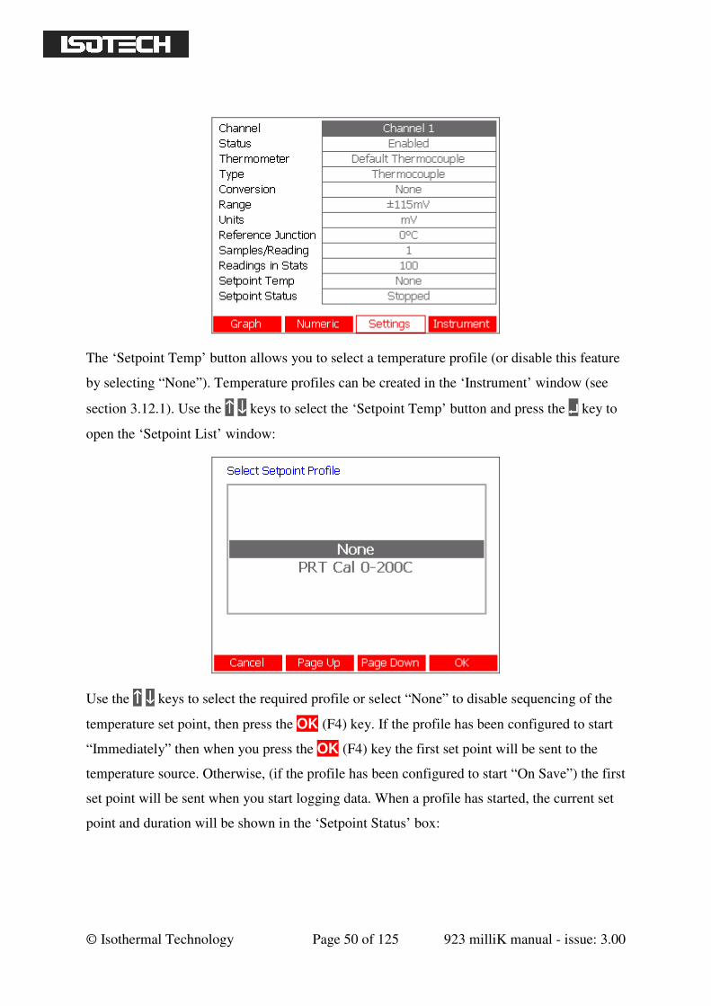
© Isothermal Technology Page 50 of 125 923 milliK manual - issue: 3.00
The ‘Setpoint Temp’ button allows you to select a temperature profile (or disable this feature
by selecting “None”). Temperature profiles can be created in the ‘Instrument’ window (see
section 3.12.1). Use the ↑↑↑↑ ↓↓↓↓ keys to select the ‘Setpoint Temp’ button and press the ↵↵↵↵ key to
open the ‘Setpoint List’ window:
Use the ↑↑↑↑ ↓↓↓↓ keys to select the required profile or select “None” to disable sequencing of the
temperature set point, then press the OK (F4) key. If the profile has been configured to start
“Immediately” then when you press the OK (F4) key the first set point will be sent to the
temperature source. Otherwise, (if the profile has been configured to start “On Save”) the first
set point will be sent when you start logging data. When a profile has started, the current set
point and duration will be shown in the ‘Setpoint Status’ box:
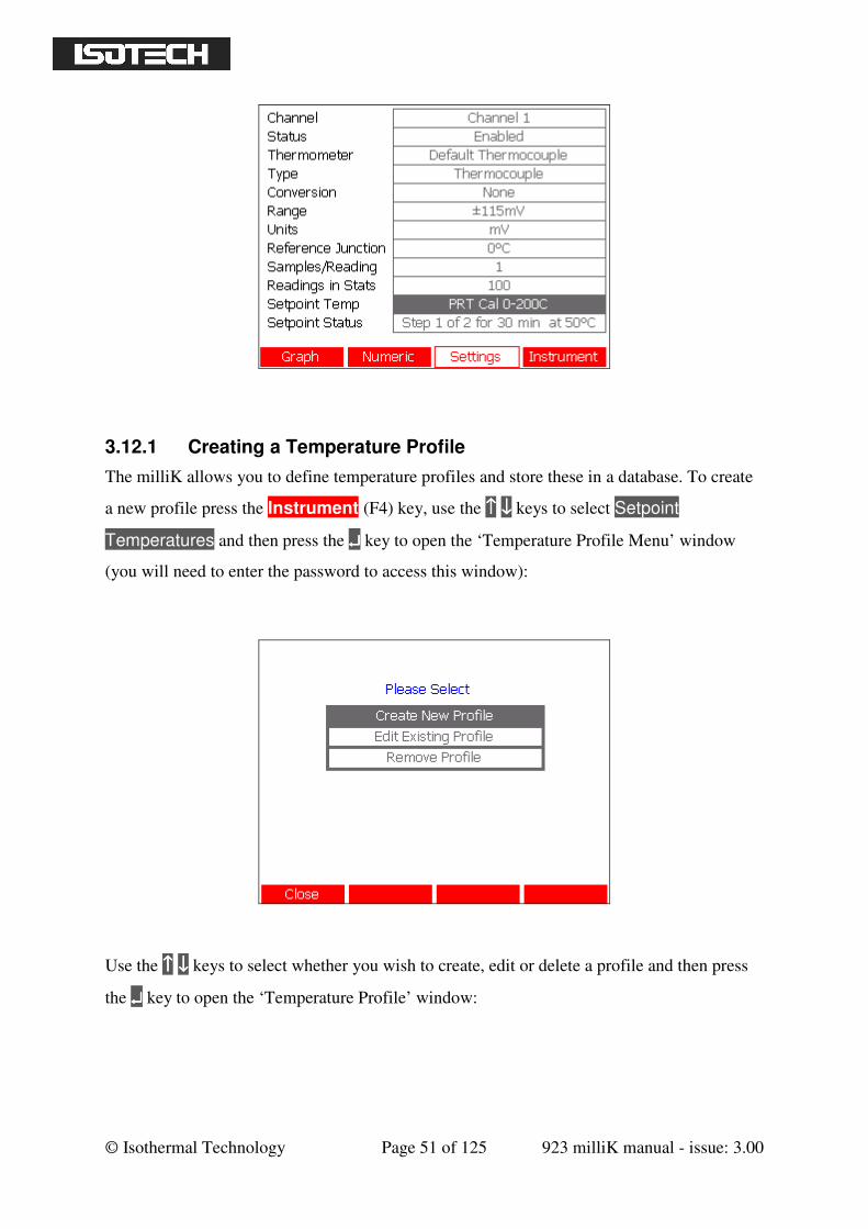
© Isothermal Technology Page 51 of 125 923 milliK manual - issue: 3.00
3.12.1 Creating a Temperature Profile
The milliK allows you to define temperature profiles and store these in a database. To create
a new profile press the Instrument (F4) key, use the ↑↑↑↑ ↓↓↓↓ keys to select Setpoint
Temperatures and then press the ↵↵↵↵ key to open the ‘Temperature Profile Menu’ window
(you will need to enter the password to access this window):
Use the ↑↑↑↑ ↓↓↓↓ keys to select whether you wish to create, edit or delete a profile and then press
the ↵↵↵↵ key to open the ‘Temperature Profile’ window:
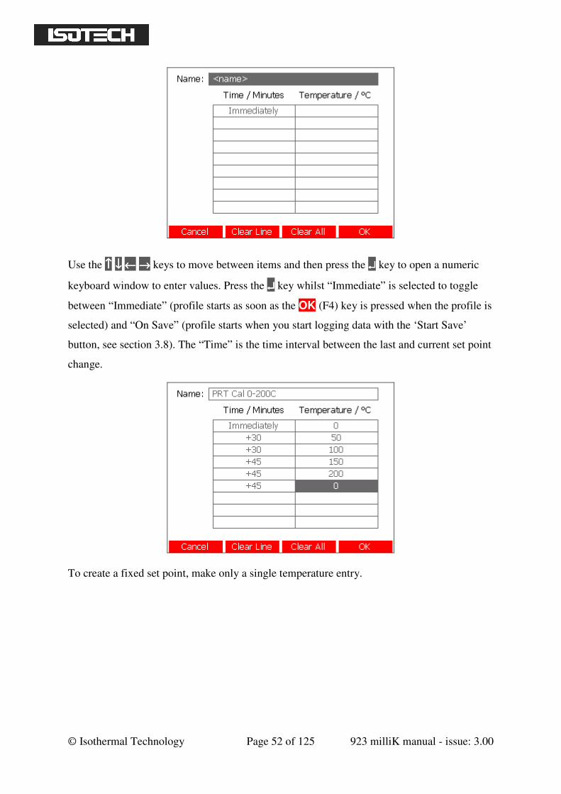
© Isothermal Technology Page 52 of 125 923 milliK manual - issue: 3.00
Use the ↑↑↑↑ ↓↓↓↓ ←←←← →→→→ keys to move between items and then press the ↵↵↵↵ key to open a numeric
keyboard window to enter values. Press the ↵↵↵↵ key whilst “Immediate” is selected to toggle
between “Immediate” (profile starts as soon as the OK (F4) key is pressed when the profile is
selected) and “On Save” (profile starts when you start logging data with the ‘Start Save’
button, see section 3.8). The “Time” is the time interval between the last and current set point
change.
To create a fixed set point, make only a single temperature entry.
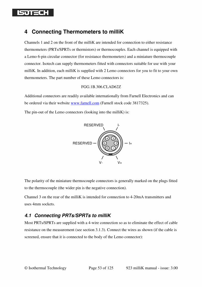
© Isothermal Technology Page 53 of 125 923 milliK manual - issue: 3.00
4 Connecting Thermometers to milliK
Channels 1 and 2 on the front of the milliK are intended for connection to either resistance
thermometers (PRTs/SPRTs or thermistors) or thermocouples. Each channel is equipped with
a Lemo 6-pin circular connector (for resistance thermometers) and a miniature thermocouple
connector. Isotech can supply thermometers fitted with connectors suitable for use with your
milliK. In addition, each milliK is supplied with 2 Lemo connectors for you to fit to your own
thermometers. The part number of these Lemo connectors is:
FGG.1B.306.CLAD62Z
Additional connectors are readily available internationally from Farnell Electronics and can
be ordered via their website www.farnell.com (Farnell stock code 3817325).
The pin-out of the Lemo connectors (looking into the milliK) is:
4
5
6 1
2
I-
I+
V+V-
RESERVED
RESERVED
3
The polarity of the miniature thermocouple connectors is generally marked on the plugs fitted
to the thermocouple (the wider pin is the negative connection).
Channel 3 on the rear of the milliK is intended for connection to 4-20mA transmitters and
uses 4mm sockets.
4.1 Connecting PRTs/SPRTs to milliK
Most PRTs/SPRTs are supplied with a 4-wire connection so as to eliminate the effect of cable
resistance on the measurement (see section 3.1.3). Connect the wires as shown (if the cable is
screened, ensure that it is connected to the body of the Lemo connector):
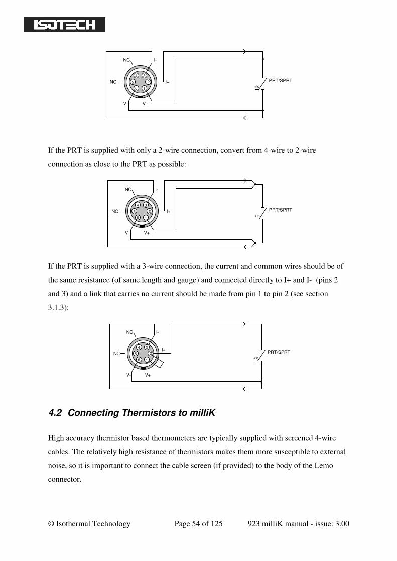
© Isothermal Technology Page 54 of 125 923 milliK manual - issue: 3.00
4
5
6 1
2
I-
I+
V+V-
3
+tc
PRT/SPRTNC
NC
If the PRT is supplied with only a 2-wire connection, convert from 4-wire to 2-wire
connection as close to the PRT as possible:
4
5
6 1
2
I-
I+
V+V-
3
+tc
PRT/SPRTNC
NC
If the PRT is supplied with a 3-wire connection, the current and common wires should be of
the same resistance (of same length and gauge) and connected directly to I+ and I- (pins 2
and 3) and a link that carries no current should be made from pin 1 to pin 2 (see section
3.1.3):
4
5
6 1
2
I-
I+
V+V-
3
+tc
PRT/SPRTNC
NC
4.2 Connecting Thermistors to milliK
High accuracy thermistor based thermometers are typically supplied with screened 4-wire
cables. The relatively high resistance of thermistors makes them more susceptible to external
noise, so it is important to connect the cable screen (if provided) to the body of the Lemo
connector.
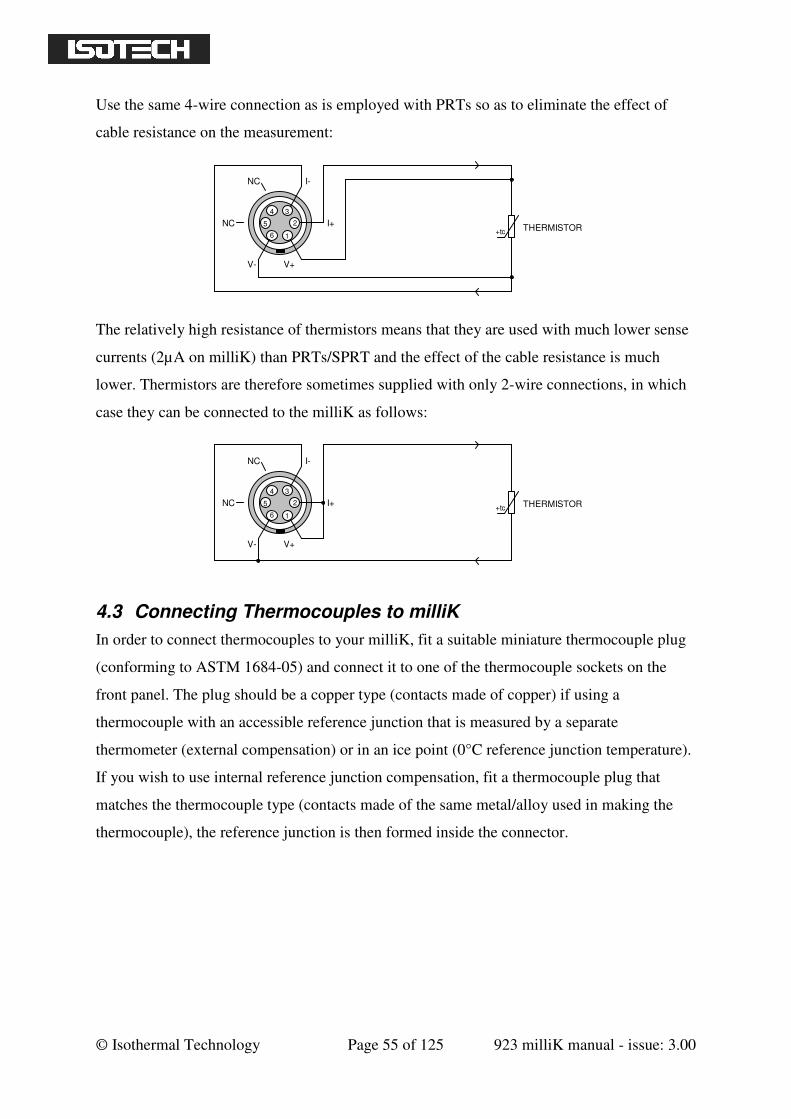
© Isothermal Technology Page 55 of 125 923 milliK manual - issue: 3.00
Use the same 4-wire connection as is employed with PRTs so as to eliminate the effect of
cable resistance on the measurement:
4
5
6 1
2
I-
I+
V+V-
3
+tc THERMISTORNC
NC
The relatively high resistance of thermistors means that they are used with much lower sense
currents (2µA on milliK) than PRTs/SPRT and the effect of the cable resistance is much
lower. Thermistors are therefore sometimes supplied with only 2-wire connections, in which
case they can be connected to the milliK as follows:
4
5
6 1
2
I-
I+
V+V-
3
+tc THERMISTORNC
NC
4.3 Connecting Thermocouples to milliK
In order to connect thermocouples to your milliK, fit a suitable miniature thermocouple plug
(conforming to ASTM 1684-05) and connect it to one of the thermocouple sockets on the
front panel. The plug should be a copper type (contacts made of copper) if using a
thermocouple with an accessible reference junction that is measured by a separate
thermometer (external compensation) or in an ice point (0°C reference junction temperature).
If you wish to use internal reference junction compensation, fit a thermocouple plug that
matches the thermocouple type (contacts made of the same metal/alloy used in making the
thermocouple), the reference junction is then formed inside the connector.
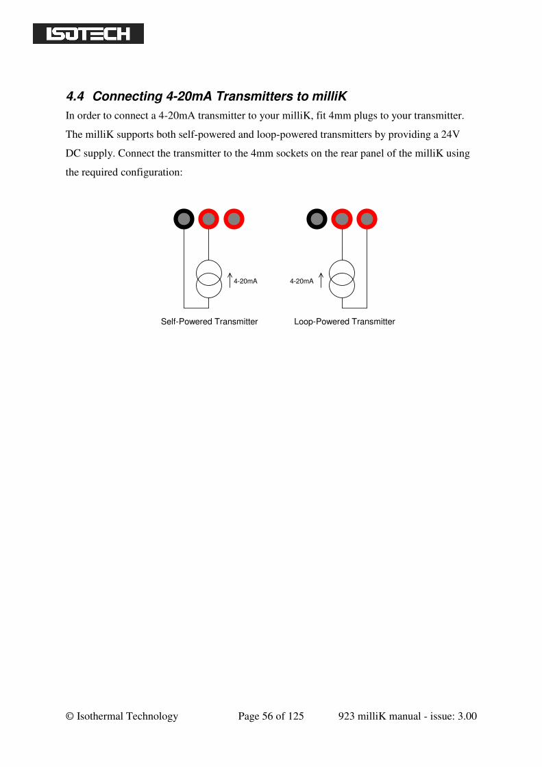
© Isothermal Technology Page 56 of 125 923 milliK manual - issue: 3.00
4.4 Connecting 4-20mA Transmitters to milliK
In order to connect a 4-20mA transmitter to your milliK, fit 4mm plugs to your transmitter.
The milliK supports both self-powered and loop-powered transmitters by providing a 24V
DC supply. Connect the transmitter to the 4mm sockets on the rear panel of the milliK using
the required configuration:
4-20mA 4-20mA
Self-Powered Transmitter Loop-Powered Transmitter
© Isothermal Technology Page 57 of 125 923 milliK manual - issue: 3.00
5 Calibration
The calibration of your milliK can be checked by applying standards to the inputs and noting
the indicated readings.
The milliK includes calibration software that allows you to adjust its calibration. The process
involves attaching suitable standards to the inputs and entering the values of these standards,
the calibration software then monitors the measured values and applies any required
corrections. The calibration data is stored in an internal comma-separated variable (CSV) file
that includes the whole calibration history (time/date stamped) back to its original factory
calibration. The calibration file can be exported to a USB drive so that it can be read (for
example, by importing it into Microsoft Excel™). The calibration software requires you to
enter additional information (such as model/serial numbers of the standards used) in order to
document the calibration history of your milliK.
Typically, a calibration process will involve measuring the pre-adjustment calibration of the
milliK, then making any necessary calibration adjustments and finally checking the
calibration after adjustment. The calibration should be checked or adjusted in a temperature
controlled environment between 19 and 25°C. The milliK should be powered up (press the
Start key (F4) in the opening screen to ensure that the measurement system is initialised and
running) and left to stabilise in the calibration environment for at least 3 hours before
checking or adjusting its calibration.
All of the adjustment is implemented in software (there are no adjustment potentiometers
inside the milliK so as to maximise reliability and provide adjustment that does not drift with
time or temperature). The milliK provides the following software adjustments:
Gain adjustment for the 115Ω range
Gain adjustment for the 460Ω range
Gain adjustment for the 500k Ω range
Voltage offset adjustment for Channel 1
Voltage offset adjustment for Channel 2
Gain adjustment for the 115mV range
Gain adjustment for the 30mA (4-20mA input) range
Offset adjustment for the internal reference junction sensor
The gain adjustments are common to all channels. There are no zero adjustments for the
resistance ranges since the zero readings are more than adequate (by design) without the need
for any adjustment.
© Isothermal Technology Page 58 of 125 923 milliK manual - issue: 3.00
5.1 Standards Required for Calibration
The following standards are recommended for checking or adjusting the calibration:
A 4-terminal short circuit (see section 5.1.1 for details of how to make one)
A calibrated 100Ω resistor of suitable quality.
A calibrated 400Ω resistor of suitable quality
A calibrated 500kΩ resistor of suitable quality
A 0mV short-circuit connected to a miniature thermocouple plug (see section 5.1.2 for
details of how to make one)
A 10mA precision current reference, such as the Metron Designs I-REF2. This is used
to calibrate the 4-20mA input, but it can also be used in calibrating the 115mV input
by connecting it to a calibrated 10Ω resistor of suitable quality to generate a nominal
100mV calibration signal. A 100mV signal source can be used to check and adjust the
voltage measurement system, but since we are trying to calibrate at the <1µV level,
suitable calibration sources are expensive. Since you already need a 10mA source to
calibrate the 4-20mA input, using a calibrated 10Ω resistor to generate the signal
offers a reliable and inexpensive solution.
A calibrated 10Ω resistor for use with the 10mA source to generate a 100mV signal
A thermocouple of adequate quality. A type T thermocouple is suitable since it has a
high sensitivity near ambient temperatures and is readily available.
All the calibrated resistors used should be either a Wilkins resistance standard or a high
stability foil resistor such as a hermetically sealed Vishay Z-foil resistor (or the H series for
the 10Ω resistor). The resistors should be maintained in a stable temperature environment
(such as a silicone oil bath) whose temperature is near to the resistor’s calibration temperature
and that is monitored so that compensation can be applied for its temperature coefficient of
resistance (TCR).
5.1.1 Making a 4-Terminal Short-Circuit
A 4-terminal short circuit is a connection that measures as 0Ω when measured as a 4-terminal
resistance. It can be fabricated using standard copper wire by shorting together the current
connections and the voltage connections separately and then linking together these two short-
circuits with a single connection:
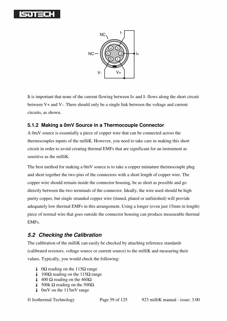
© Isothermal Technology Page 59 of 125 923 milliK manual - issue: 3.00
4
5
6 1
2
I-
I+
V+V-
3
NC
NC
It is important that none of the current flowing between I+ and I- flows along the short circuit
between V+ and V-. There should only be a single link between the voltage and current
circuits, as shown.
5.1.2 Making a 0mV Source in a Thermocouple Connector
A 0mV source is essentially a piece of copper wire that can be connected across the
thermocouples inputs of the milliK. However, you need to take care in making this short
circuit in order to avoid creating thermal EMFs that are significant for an instrument as
sensitive as the milliK.
The best method for making a 0mV source is to take a copper miniature thermocouple plug
and short together the two pins of the connectors with a short length of copper wire. The
copper wire should remain inside the connector housing, be as short as possible and go
directly between the two terminals of the connector. Ideally, the wire used should be high
purity copper, but single stranded copper wire (tinned, plated or unfinished) will provide
adequately low thermal EMFs in this arrangement. Using a longer (even just 15mm in length)
piece of normal wire that goes outside the connector housing can produce measurable thermal
EMFs.
5.2 Checking the Calibration
The calibration of the milliK can easily be checked by attaching reference standards
(calibrated resistors, voltage source or current source) to the milliK and measuring their
values. Typically, you would check the following:
0Ω reading on the 115Ω range
100Ω reading on the 115Ω range
400 Ω reading on the 460Ω
500k Ω reading on the 500Ω
0mV on the 115mV range
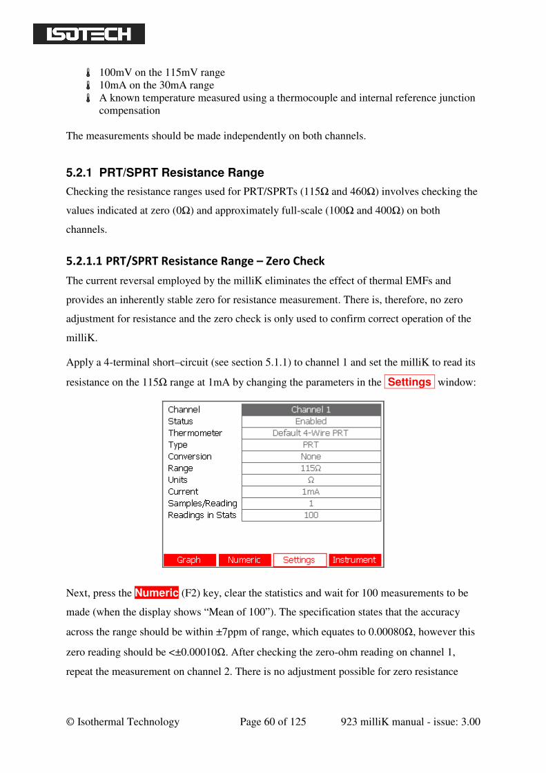
© Isothermal Technology Page 60 of 125 923 milliK manual - issue: 3.00
100mV on the 115mV range
10mA on the 30mA range
A known temperature measured using a thermocouple and internal reference junction
compensation
The measurements should be made independently on both channels.
5.2.1 PRT/SPRT Resistance Range
Checking the resistance ranges used for PRT/SPRTs (115Ω and 460Ω) involves checking the
values indicated at zero (0Ω) and approximately full-scale (100Ω and 400Ω) on both
channels.
5.2.1.1 PRT/SPRT Resistance Range – Zero Check
The current reversal employed by the milliK eliminates the effect of thermal EMFs and
provides an inherently stable zero for resistance measurement. There is, therefore, no zero
adjustment for resistance and the zero check is only used to confirm correct operation of the
milliK.
Apply a 4-terminal short–circuit (see section 5.1.1) to channel 1 and set the milliK to read its
resistance on the 115Ω range at 1mA by changing the parameters in the Settings window:
Next, press the Numeric (F2) key, clear the statistics and wait for 100 measurements to be
made (when the display shows “Mean of 100”). The specification states that the accuracy
across the range should be within ±7ppm of range, which equates to 0.00080Ω, however this
zero reading should be <±0.00010Ω. After checking the zero-ohm reading on channel 1,
repeat the measurement on channel 2. There is no adjustment possible for zero resistance
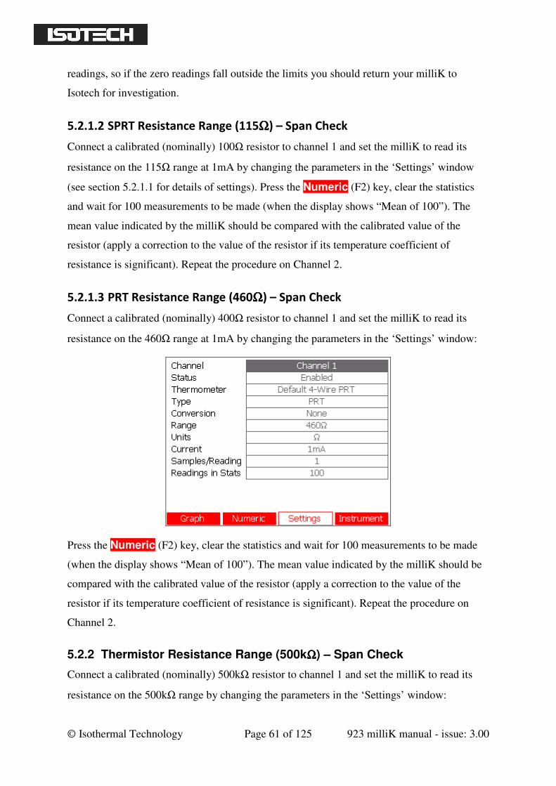
© Isothermal Technology Page 61 of 125 923 milliK manual - issue: 3.00
readings, so if the zero readings fall outside the limits you should return your milliK to
Isotech for investigation.
5.2.1.2 SPRT Resistance Range (115ΩΩΩΩ) – Span Check
Connect a calibrated (nominally) 100Ω resistor to channel 1 and set the milliK to read its
resistance on the 115Ω range at 1mA by changing the parameters in the ‘Settings’ window
(see section 5.2.1.1 for details of settings). Press the Numeric (F2) key, clear the statistics
and wait for 100 measurements to be made (when the display shows “Mean of 100”). The
mean value indicated by the milliK should be compared with the calibrated value of the
resistor (apply a correction to the value of the resistor if its temperature coefficient of
resistance is significant). Repeat the procedure on Channel 2.
5.2.1.3 PRT Resistance Range (460ΩΩΩΩ) – Span Check
Connect a calibrated (nominally) 400Ω resistor to channel 1 and set the milliK to read its
resistance on the 460Ω range at 1mA by changing the parameters in the ‘Settings’ window:
Press the Numeric (F2) key, clear the statistics and wait for 100 measurements to be made
(when the display shows “Mean of 100”). The mean value indicated by the milliK should be
compared with the calibrated value of the resistor (apply a correction to the value of the
resistor if its temperature coefficient of resistance is significant). Repeat the procedure on
Channel 2.
5.2.2 Thermistor Resistance Range (500kΩΩΩΩ) – Span Check
Connect a calibrated (nominally) 500kΩ resistor to channel 1 and set the milliK to read its
resistance on the 500kΩ range by changing the parameters in the ‘Settings’ window:
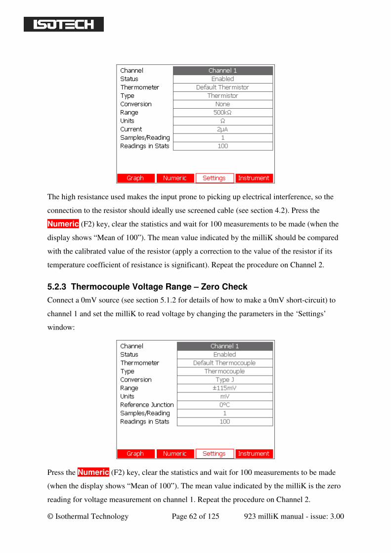
© Isothermal Technology Page 62 of 125 923 milliK manual - issue: 3.00
The high resistance used makes the input prone to picking up electrical interference, so the
connection to the resistor should ideally use screened cable (see section 4.2). Press the
Numeric (F2) key, clear the statistics and wait for 100 measurements to be made (when the
display shows “Mean of 100”). The mean value indicated by the milliK should be compared
with the calibrated value of the resistor (apply a correction to the value of the resistor if its
temperature coefficient of resistance is significant). Repeat the procedure on Channel 2.
5.2.3 Thermocouple Voltage Range – Zero Check
Connect a 0mV source (see section 5.1.2 for details of how to make a 0mV short-circuit) to
channel 1 and set the milliK to read voltage by changing the parameters in the ‘Settings’
window:
Press the Numeric (F2) key, clear the statistics and wait for 100 measurements to be made
(when the display shows “Mean of 100”). The mean value indicated by the milliK is the zero
reading for voltage measurement on channel 1. Repeat the procedure on Channel 2.
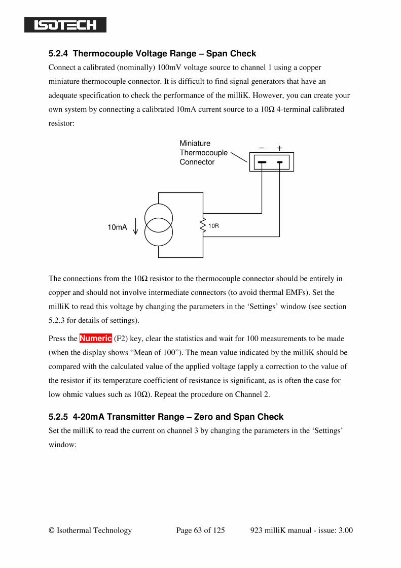
© Isothermal Technology Page 63 of 125 923 milliK manual - issue: 3.00
5.2.4 Thermocouple Voltage Range – Span Check
Connect a calibrated (nominally) 100mV voltage source to channel 1 using a copper
miniature thermocouple connector. It is difficult to find signal generators that have an
adequate specification to check the performance of the milliK. However, you can create your
own system by connecting a calibrated 10mA current source to a 10Ω 4-terminal calibrated
resistor:
Thermocouple
Connector
10R10mA
Miniature
The connections from the 10Ω resistor to the thermocouple connector should be entirely in
copper and should not involve intermediate connectors (to avoid thermal EMFs). Set the
milliK to read this voltage by changing the parameters in the ‘Settings’ window (see section
5.2.3 for details of settings).
Press the Numeric (F2) key, clear the statistics and wait for 100 measurements to be made
(when the display shows “Mean of 100”). The mean value indicated by the milliK should be
compared with the calculated value of the applied voltage (apply a correction to the value of
the resistor if its temperature coefficient of resistance is significant, as is often the case for
low ohmic values such as 10Ω). Repeat the procedure on Channel 2.
5.2.5 4-20mA Transmitter Range – Zero and Span Check
Set the milliK to read the current on channel 3 by changing the parameters in the ‘Settings’
window:
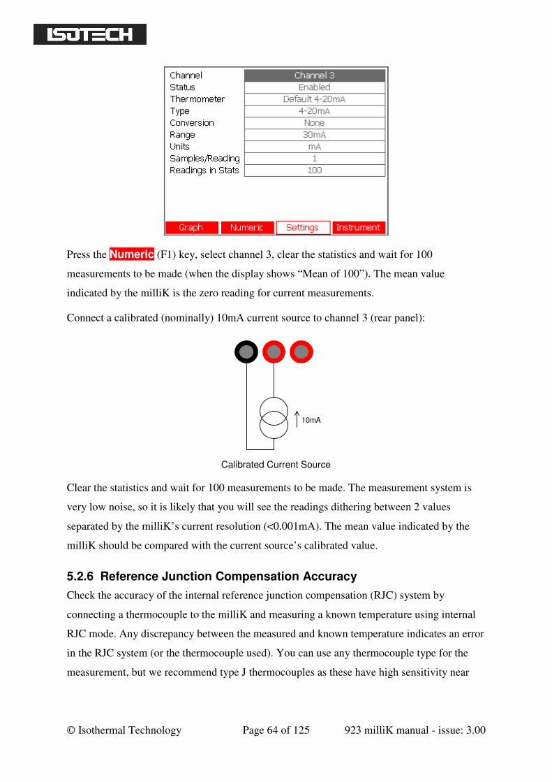
© Isothermal Technology Page 64 of 125 923 milliK manual - issue: 3.00
Press the Numeric (F1) key, select channel 3, clear the statistics and wait for 100
measurements to be made (when the display shows “Mean of 100”). The mean value
indicated by the milliK is the zero reading for current measurements.
Connect a calibrated (nominally) 10mA current source to channel 3 (rear panel):
10mA
Calibrated Current Source
Clear the statistics and wait for 100 measurements to be made. The measurement system is
very low noise, so it is likely that you will see the readings dithering between 2 values
separated by the milliK’s current resolution (<0.001mA). The mean value indicated by the
milliK should be compared with the current source’s calibrated value.
5.2.6 Reference Junction Compensation Accuracy
Check the accuracy of the internal reference junction compensation (RJC) system by
connecting a thermocouple to the milliK and measuring a known temperature using internal
RJC mode. Any discrepancy between the measured and known temperature indicates an error
in the RJC system (or the thermocouple used). You can use any thermocouple type for the
measurement, but we recommend type J thermocouples as these have high sensitivity near
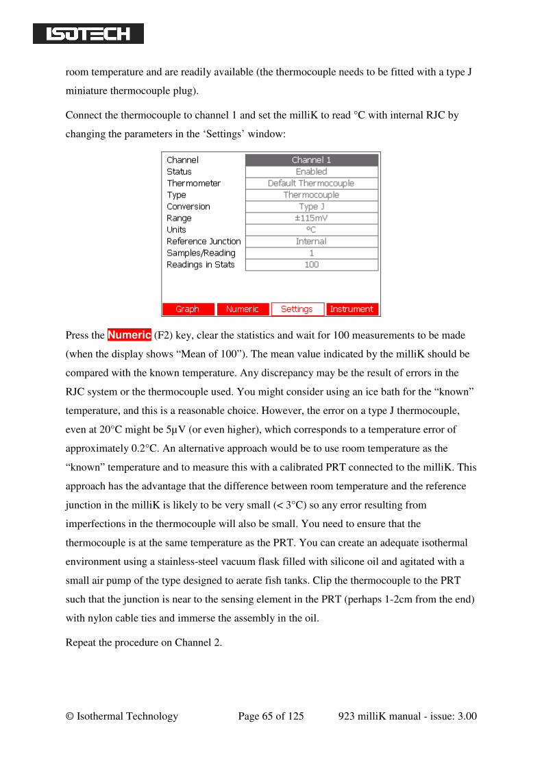
© Isothermal Technology Page 65 of 125 923 milliK manual - issue: 3.00
room temperature and are readily available (the thermocouple needs to be fitted with a type J
miniature thermocouple plug).
Connect the thermocouple to channel 1 and set the milliK to read °C with internal RJC by
changing the parameters in the ‘Settings’ window:
Press the Numeric (F2) key, clear the statistics and wait for 100 measurements to be made
(when the display shows “Mean of 100”). The mean value indicated by the milliK should be
compared with the known temperature. Any discrepancy may be the result of errors in the
RJC system or the thermocouple used. You might consider using an ice bath for the “known”
temperature, and this is a reasonable choice. However, the error on a type J thermocouple,
even at 20°C might be 5µV (or even higher), which corresponds to a temperature error of
approximately 0.2°C. An alternative approach would be to use room temperature as the
“known” temperature and to measure this with a calibrated PRT connected to the milliK. This
approach has the advantage that the difference between room temperature and the reference
junction in the milliK is likely to be very small (< 3°C) so any error resulting from
imperfections in the thermocouple will also be small. You need to ensure that the
thermocouple is at the same temperature as the PRT. You can create an adequate isothermal
environment using a stainless-steel vacuum flask filled with silicone oil and agitated with a
small air pump of the type designed to aerate fish tanks. Clip the thermocouple to the PRT
such that the junction is near to the sensing element in the PRT (perhaps 1-2cm from the end)
with nylon cable ties and immerse the assembly in the oil.
Repeat the procedure on Channel 2.
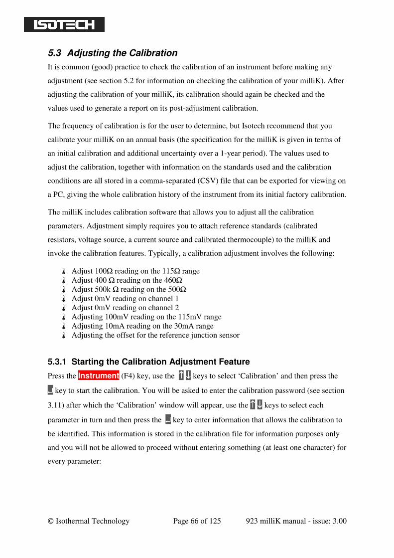
© Isothermal Technology Page 66 of 125 923 milliK manual - issue: 3.00
5.3 Adjusting the Calibration
It is common (good) practice to check the calibration of an instrument before making any
adjustment (see section 5.2 for information on checking the calibration of your milliK). After
adjusting the calibration of your milliK, its calibration should again be checked and the
values used to generate a report on its post-adjustment calibration.
The frequency of calibration is for the user to determine, but Isotech recommend that you
calibrate your milliK on an annual basis (the specification for the milliK is given in terms of
an initial calibration and additional uncertainty over a 1-year period). The values used to
adjust the calibration, together with information on the standards used and the calibration
conditions are all stored in a comma-separated (CSV) file that can be exported for viewing on
a PC, giving the whole calibration history of the instrument from its initial factory calibration.
The milliK includes calibration software that allows you to adjust all the calibration
parameters. Adjustment simply requires you to attach reference standards (calibrated
resistors, voltage source, a current source and calibrated thermocouple) to the milliK and
invoke the calibration features. Typically, a calibration adjustment involves the following:
Adjust 100Ω reading on the 115Ω range
Adjust 400 Ω reading on the 460Ω
Adjust 500k Ω reading on the 500Ω
Adjust 0mV reading on channel 1
Adjust 0mV reading on channel 2
Adjusting 100mV reading on the 115mV range
Adjusting 10mA reading on the 30mA range
Adjusting the offset for the reference junction sensor
5.3.1 Starting the Calibration Adjustment Feature
Press the Instrument (F4) key, use the ↑↑↑↑ ↓↓↓↓ keys to select ‘Calibration’ and then press the
↵↵↵↵ key to start the calibration. You will be asked to enter the calibration password (see section
3.11) after which the ‘Calibration’ window will appear, use the ↑↑↑↑ ↓↓↓↓ keys to select each
parameter in turn and then press the ↵↵↵↵ key to enter information that allows the calibration to
be identified. This information is stored in the calibration file for information purposes only
and you will not be allowed to proceed without entering something (at least one character) for
every parameter:
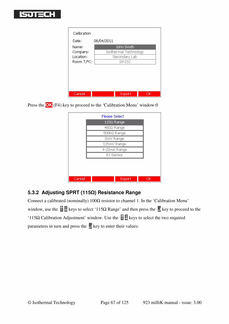
© Isothermal Technology Page 67 of 125 923 milliK manual - issue: 3.00
Press the OK (F4) key to proceed to the ‘Calibration Menu’ window:0
5.3.2 Adjusting SPRT (115Ω) Resistance Range
Connect a calibrated (nominally) 100Ω resistor to channel 1. In the ‘Calibration Menu’
window, use the ↑↑↑↑ ↓↓↓↓ keys to select ‘115Ω Range’ and then press the ↵↵↵↵ key to proceed to the
‘115Ω Calibration Adjustment’ window. Use the ↑↑↑↑ ↓↓↓↓ keys to select the two required
parameters in turn and press the ↵↵↵↵ key to enter their values:
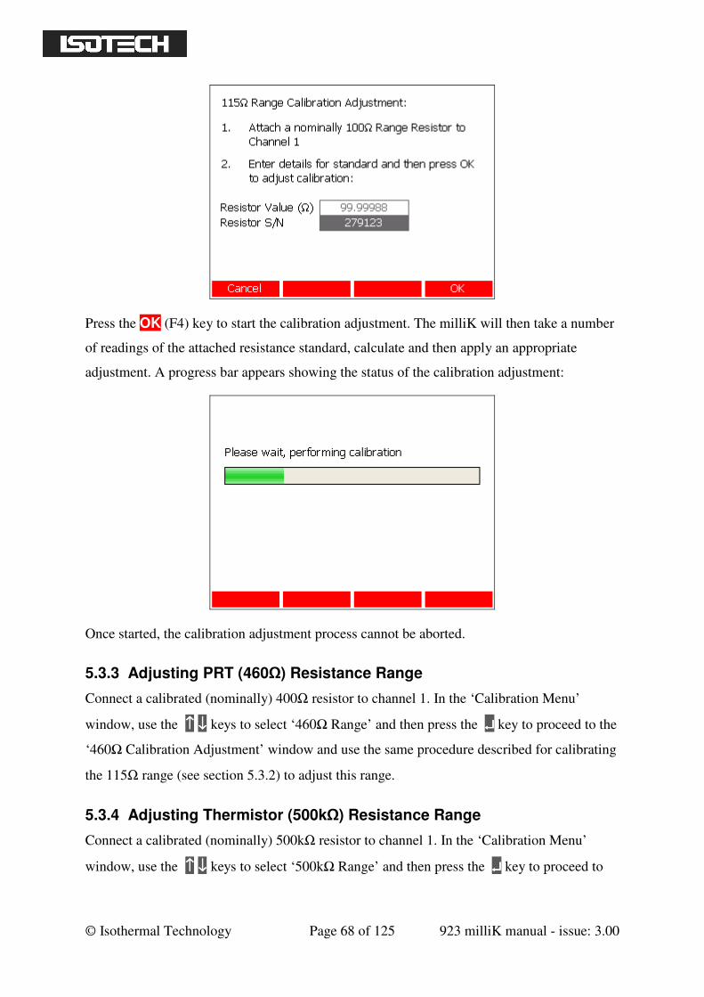
© Isothermal Technology Page 68 of 125 923 milliK manual - issue: 3.00
Press the OK (F4) key to start the calibration adjustment. The milliK will then take a number
of readings of the attached resistance standard, calculate and then apply an appropriate
adjustment. A progress bar appears showing the status of the calibration adjustment:
Once started, the calibration adjustment process cannot be aborted.
5.3.3 Adjusting PRT (460Ω) Resistance Range
Connect a calibrated (nominally) 400Ω resistor to channel 1. In the ‘Calibration Menu’
window, use the ↑↑↑↑ ↓↓↓↓ keys to select ‘460Ω Range’ and then press the ↵↵↵↵ key to proceed to the
‘460Ω Calibration Adjustment’ window and use the same procedure described for calibrating
the 115Ω range (see section 5.3.2) to adjust this range.
5.3.4 Adjusting Thermistor (500kΩ) Resistance Range
Connect a calibrated (nominally) 500kΩ resistor to channel 1. In the ‘Calibration Menu’
window, use the ↑↑↑↑ ↓↓↓↓ keys to select ‘500kΩ Range’ and then press the ↵↵↵↵ key to proceed to
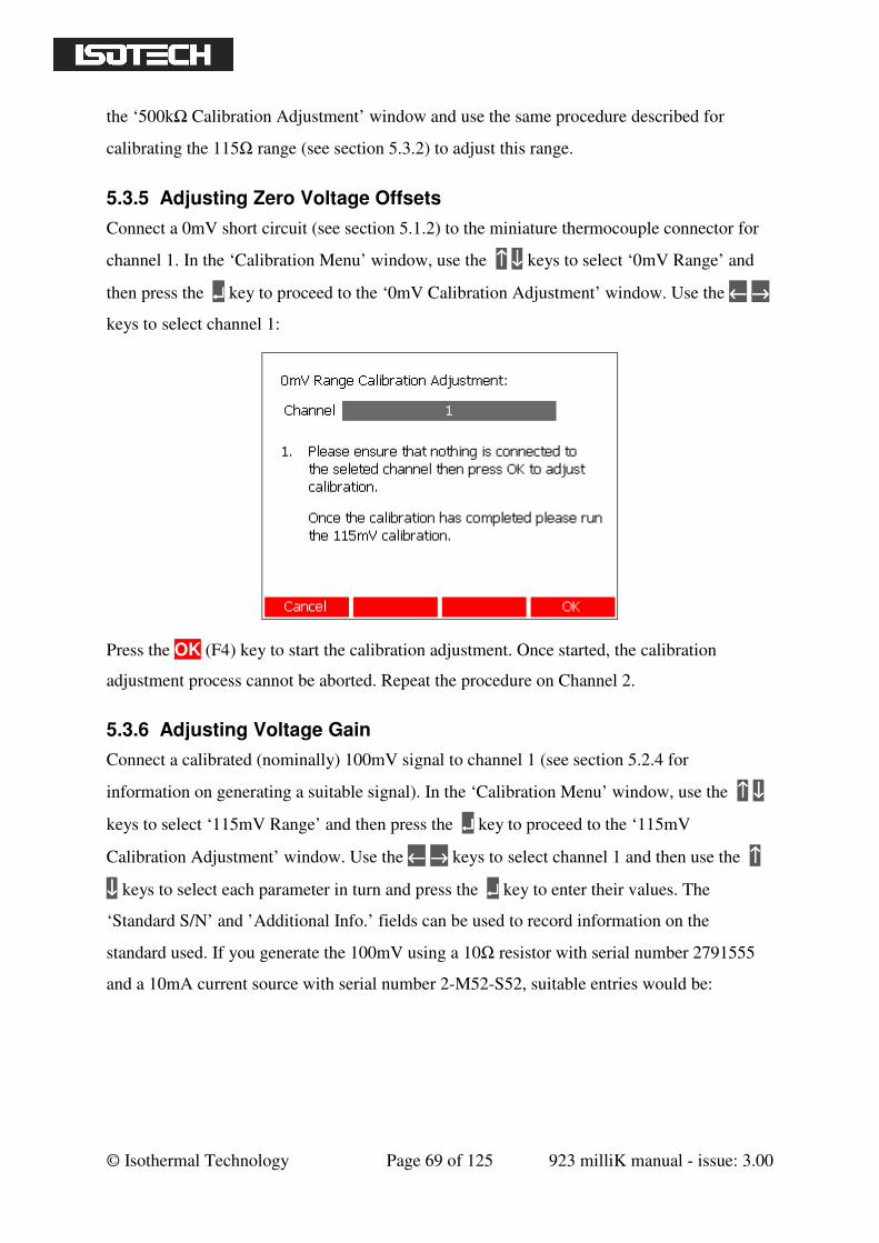
© Isothermal Technology Page 69 of 125 923 milliK manual - issue: 3.00
the ‘500kΩ Calibration Adjustment’ window and use the same procedure described for
calibrating the 115Ω range (see section 5.3.2) to adjust this range.
5.3.5 Adjusting Zero Voltage Offsets
Connect a 0mV short circuit (see section 5.1.2) to the miniature thermocouple connector for
channel 1. In the ‘Calibration Menu’ window, use the ↑↑↑↑ ↓↓↓↓ keys to select ‘0mV Range’ and
then press the ↵↵↵↵ key to proceed to the ‘0mV Calibration Adjustment’ window. Use the ←←←← →→→→
keys to select channel 1:
Press the OK (F4) key to start the calibration adjustment. Once started, the calibration
adjustment process cannot be aborted. Repeat the procedure on Channel 2.
5.3.6 Adjusting Voltage Gain
Connect a calibrated (nominally) 100mV signal to channel 1 (see section 5.2.4 for
information on generating a suitable signal). In the ‘Calibration Menu’ window, use the ↑↑↑↑ ↓↓↓↓
keys to select ‘115mV Range’ and then press the ↵↵↵↵ key to proceed to the ‘115mV
Calibration Adjustment’ window. Use the ←←←← →→→→ keys to select channel 1 and then use the ↑↑↑↑
↓↓↓↓ keys to select each parameter in turn and press the ↵↵↵↵ key to enter their values. The
‘Standard S/N’ and ’Additional Info.’ fields can be used to record information on the
standard used. If you generate the 100mV using a 10Ω resistor with serial number 2791555
and a 10mA current source with serial number 2-M52-S52, suitable entries would be:
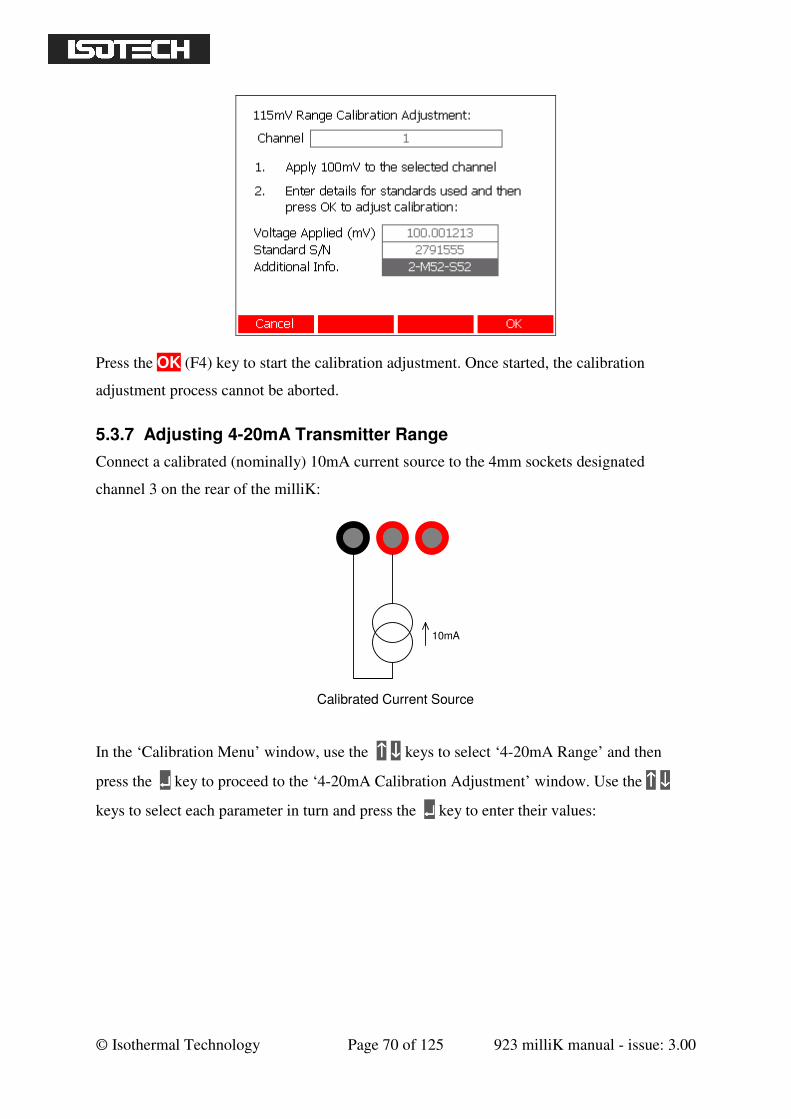
© Isothermal Technology Page 70 of 125 923 milliK manual - issue: 3.00
Press the OK (F4) key to start the calibration adjustment. Once started, the calibration
adjustment process cannot be aborted.
5.3.7 Adjusting 4-20mA Transmitter Range
Connect a calibrated (nominally) 10mA current source to the 4mm sockets designated
channel 3 on the rear of the milliK:
10mA
Calibrated Current Source
In the ‘Calibration Menu’ window, use the ↑↑↑↑ ↓↓↓↓ keys to select ‘4-20mA Range’ and then
press the ↵↵↵↵ key to proceed to the ‘4-20mA Calibration Adjustment’ window. Use the ↑↑↑↑ ↓↓↓↓
keys to select each parameter in turn and press the ↵↵↵↵ key to enter their values:
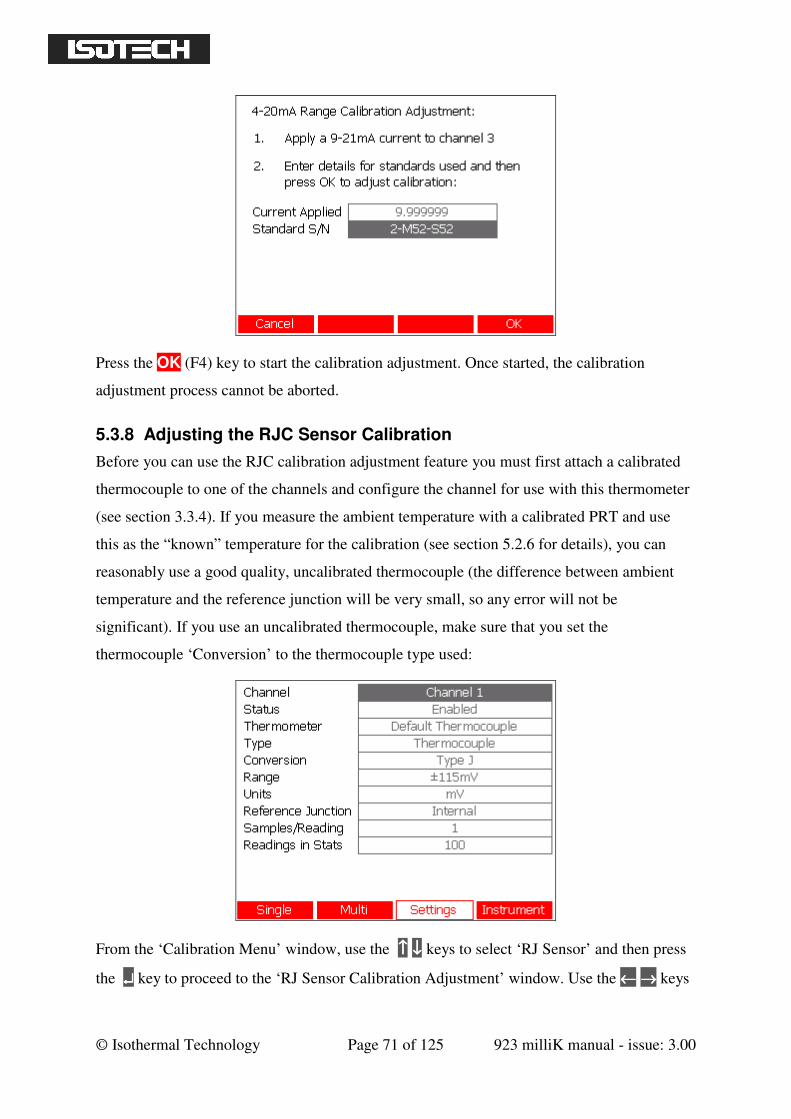
© Isothermal Technology Page 71 of 125 923 milliK manual - issue: 3.00
Press the OK (F4) key to start the calibration adjustment. Once started, the calibration
adjustment process cannot be aborted.
5.3.8 Adjusting the RJC Sensor Calibration
Before you can use the RJC calibration adjustment feature you must first attach a calibrated
thermocouple to one of the channels and configure the channel for use with this thermometer
(see section 3.3.4). If you measure the ambient temperature with a calibrated PRT and use
this as the “known” temperature for the calibration (see section 5.2.6 for details), you can
reasonably use a good quality, uncalibrated thermocouple (the difference between ambient
temperature and the reference junction will be very small, so any error will not be
significant). If you use an uncalibrated thermocouple, make sure that you set the
thermocouple ‘Conversion’ to the thermocouple type used:
From the ‘Calibration Menu’ window, use the ↑↑↑↑ ↓↓↓↓ keys to select ‘RJ Sensor’ and then press
the ↵↵↵↵ key to proceed to the ‘RJ Sensor Calibration Adjustment’ window. Use the ←←←← →→→→ keys
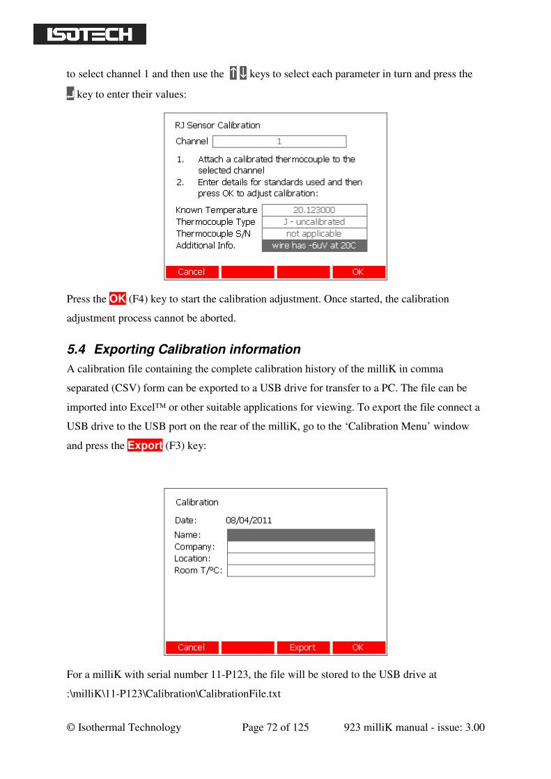
© Isothermal Technology Page 72 of 125 923 milliK manual - issue: 3.00
to select channel 1 and then use the ↑↑↑↑ ↓↓↓↓ keys to select each parameter in turn and press the
↵↵↵↵ key to enter their values:
Press the OK (F4) key to start the calibration adjustment. Once started, the calibration
adjustment process cannot be aborted.
5.4 Exporting Calibration information
A calibration file containing the complete calibration history of the milliK in comma
separated (CSV) form can be exported to a USB drive for transfer to a PC. The file can be
imported into Excel™ or other suitable applications for viewing. To export the file connect a
USB drive to the USB port on the rear of the milliK, go to the ‘Calibration Menu’ window
and press the Export (F3) key:
For a milliK with serial number 11-P123, the file will be stored to the USB drive at
:\milliK\11-P123\Calibration\CalibrationFile.txt

© Isothermal Technology Page 73 of 125 923 milliK manual - issue: 3.00
6 Maintenance and Cleaning
Your milliK is a precision electronic instrument intended for indoor use in a laboratory,
office or light industrial environment. Nonetheless, it has been designed to be as robust as is
practical and will provide many years of service, provided it is properly maintained.
The screen, touch panel and case can be cleaned with a damp (not wet) cloth. Use either a
proprietary screen cleaner (suitable for PC flat panel displays) or water and a little mild liquid
soap on a lint-free cloth to clean your milliK. Dry the screen and touch panel immediately
after cleaning with a lint-free cloth. Never use abrasive cleaners (such as ‘cream’ cleaners) or
solvents on your milliK.
Miniature thermocouple plugs are of variable quality and lower quality versions can cause
wear to the contacts in your milliK. If you feel that the thermocouple sockets on your milliK
are becoming stiff, you can apply a small amount of contact lubricant (Electrolube CG53A is
suitable: available internationally from Farnell Electronics via their website www.farnell.com
under Farnell stock code 725602) onto the blades of a thermocouple plug and insert into the
milliK thermocouple sockets several times.
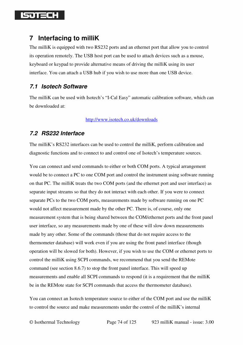
© Isothermal Technology Page 74 of 125 923 milliK manual - issue: 3.00
7 Interfacing to milliK
The milliK is equipped with two RS232 ports and an ethernet port that allow you to control
its operation remotely. The USB host port can be used to attach devices such as a mouse,
keyboard or keypad to provide alternative means of driving the milliK using its user
interface. You can attach a USB hub if you wish to use more than one USB device.
7.1 Isotech Software
The milliK can be used with Isotech’s “I-Cal Easy” automatic calibration software, which can
be downloaded at:
http://www.isotech.co.uk/downloads
7.2 RS232 Interface
The milliK’s RS232 interfaces can be used to control the milliK, perform calibration and
diagnostic functions and to connect to and control one of Isotech’s temperature sources.
You can connect and send commands to either or both COM ports. A typical arrangement
would be to connect a PC to one COM port and control the instrument using software running
on that PC. The milliK treats the two COM ports (and the ethernet port and user interface) as
separate input streams so that they do not interact with each other. If you were to connect
separate PCs to the two COM ports, measurements made by software running on one PC
would not affect measurement made by the other PC. There is, of course, only one
measurement system that is being shared between the COM/ethernet ports and the front panel
user interface, so any measurements made by one of these will slow down measurements
made by any other. Some of the commands (those that do not require access to the
thermometer database) will work even if you are using the front panel interface (though
operation will be slowed for both). However, if you wish to use the COM or ethernet ports to
control the milliK using SCPI commands, we recommend that you send the REMote
command (see section 8.6.7) to stop the front panel interface. This will speed up
measurements and enable all SCPI commands to respond (it is a requirement that the milliK
be in the REMote state for SCPI commands that access the thermometer database).
You can connect an Isotech temperature source to either of the COM port and use the milliK
to control the source and make measurements under the control of the milliK’s internal
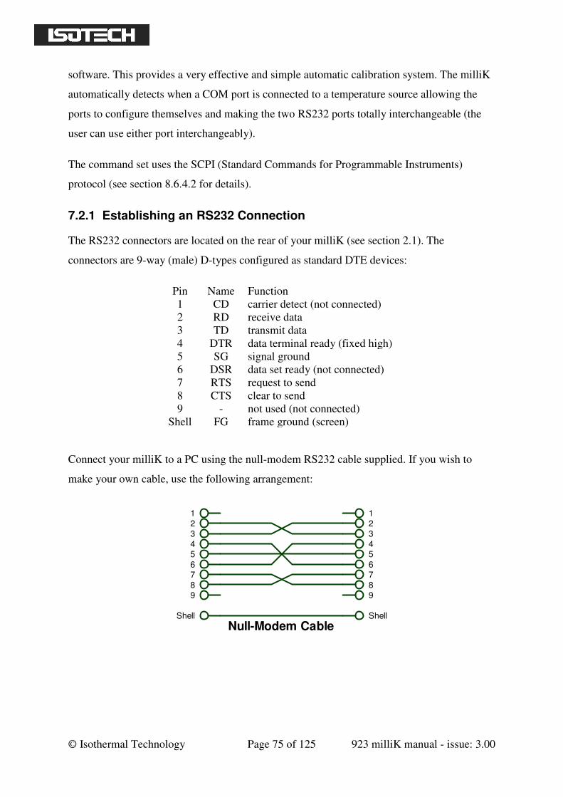
© Isothermal Technology Page 75 of 125 923 milliK manual - issue: 3.00
software. This provides a very effective and simple automatic calibration system. The milliK
automatically detects when a COM port is connected to a temperature source allowing the
ports to configure themselves and making the two RS232 ports totally interchangeable (the
user can use either port interchangeably).
The command set uses the SCPI (Standard Commands for Programmable Instruments)
protocol (see section 8.6.4.2 for details).
7.2.1 Establishing an RS232 Connection
The RS232 connectors are located on the rear of your milliK (see section 2.1). The
connectors are 9-way (male) D-types configured as standard DTE devices:
Pin Name Function
1 CD carrier detect (not connected)
2 RD receive data
3 TD transmit data
4 DTR data terminal ready (fixed high)
5 SG signal ground
6 DSR data set ready (not connected)
7 RTS request to send
8 CTS clear to send
9 - not used (not connected)
Shell FG frame ground (screen)
Connect your milliK to a PC using the null-modem RS232 cable supplied. If you wish to
make your own cable, use the following arrangement:
1
2
3
4
5
6
7
8
9
Shell
1
2
3
4
5
6
7
8
Shell
9
Null-Modem Cable
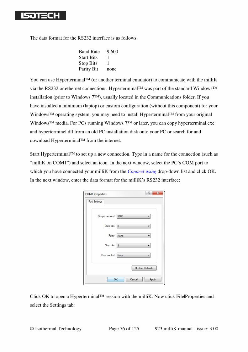
© Isothermal Technology Page 76 of 125 923 milliK manual - issue: 3.00
The data format for the RS232 interface is as follows:
Baud Rate 9,600
Start Bits 1
Stop Bits 1
Parity Bit none
You can use Hyperterminal™ (or another terminal emulator) to communicate with the milliK
via the RS232 or ethernet connections. Hyperterminal™ was part of the standard Windows™
installation (prior to Windows 7™), usually located in the Communications folder. If you
have installed a minimum (laptop) or custom configuration (without this component) for your
Windows™ operating system, you may need to install Hyperterminal™ from your original
Windows™ media. For PCs running Windows 7™ or later, you can copy hyperterminal.exe
and hyperterminel.dll from an old PC installation disk onto your PC or search for and
download Hyperterminal™ from the internet.
Start Hyperterminal™ to set up a new connection. Type in a name for the connection (such as
“milliK on COM1”) and select an icon. In the next window, select the PC’s COM port to
which you have connected your milliK from the Connect using drop-down list and click OK.
In the next window, enter the data format for the milliK’s RS232 interface:
Click OK to open a Hyperterminal™ session with the milliK. Now click File|Properties and
select the Settings tab:
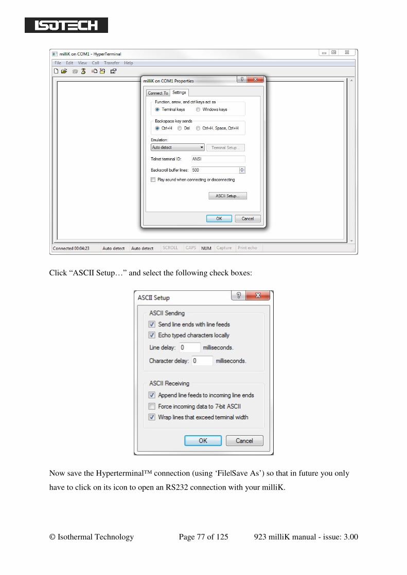
© Isothermal Technology Page 77 of 125 923 milliK manual - issue: 3.00
Click “ASCII Setup…” and select the following check boxes:
Now save the Hyperterminal™ connection (using ‘File|Save As’) so that in future you only
have to click on its icon to open an RS232 connection with your milliK.
© Isothermal Technology Page 78 of 125 923 milliK manual - issue: 3.00
Type *IDN? into Hyperterminal™ (terminate the command by pressing the carriage return or
Enter keys), the milliK should then respond with a string in the form:
Isothermal Technology, milliK,12-P3456,3.0.0
This confirms that you have successfully established an RS232 connection with your milliK.
7.3 Ethernet Interface
The milliK’s ethernet interface can be used to control the milliK and perform calibration and
diagnostic functions. The milliK treats the ethernet port, the two COM ports and the user
interface as separate input streams so that they do not interact with each other. If you were to
connect separate PCs to the ethernet port and one of the COM ports, then measurements
made by software running on one PC would not affect measurements made by the other PC.
There is, of course, only one measurement system that is being shared between the
ethernet/COM ports and the front panel user interface, so any measurements made by one of
these will slow down measurements made by any other. Some of the commands (those that
do not require access to the thermometer database) will work even if you are using the front
panel interface (though operation will be slowed for both). However, if you wish to use the
ethernet or COM ports to control the milliK using SCPI commands, we recommend that you
send the REMote command (see section 8.6.7) to stop the front panel interface. This will
speed up measurements and enable all SCPI commands to respond (it is a requirement that
the milliK be in the REMote state for SCPI commands that access the thermometer database
to respond).
There are two ways to use the ethernet interface; you can use a remote desktop facility to
control the milliK using the PC’s keyboard and mouse or you can send SCPI commands to
the milliK in the same way as using the RS232 interfaces (see section 7.1). The command set
uses the SCPI (Standard Commands for Programmable Instruments) protocol (see section
8.6.4.2 for details). These two ways of controlling the milliK using the ethernet interface can
be used at the same time.
7.3.1 Establishing an Ethernet Connection
The ethernet connector (standard RJ45) is located on the rear of your milliK (see section 2.1).
Connect this to your LAN (Local Area Network) using a standard RJ45 patch lead.
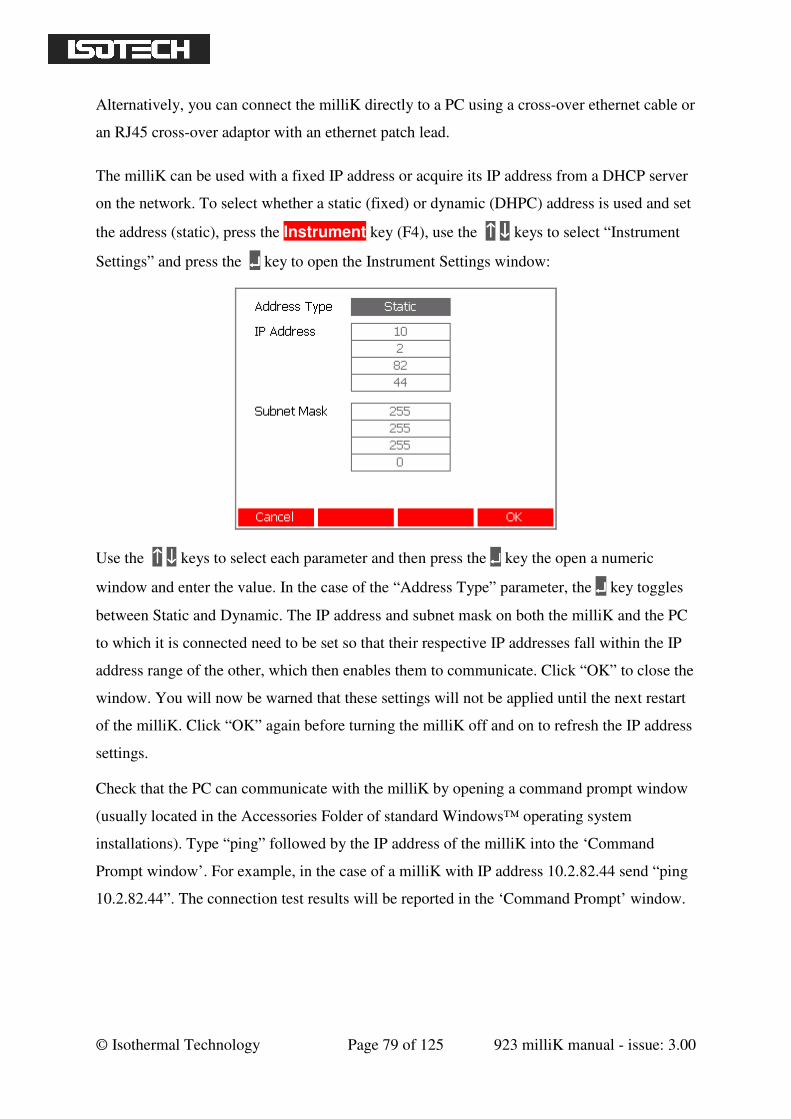
© Isothermal Technology Page 79 of 125 923 milliK manual - issue: 3.00
Alternatively, you can connect the milliK directly to a PC using a cross-over ethernet cable or
an RJ45 cross-over adaptor with an ethernet patch lead.
The milliK can be used with a fixed IP address or acquire its IP address from a DHCP server
on the network. To select whether a static (fixed) or dynamic (DHPC) address is used and set
the address (static), press the Instrument key (F4), use the ↑↑↑↑ ↓↓↓↓ keys to select “Instrument
Settings” and press the ↵↵↵↵ key to open the Instrument Settings window:
Use the ↑↑↑↑ ↓↓↓↓ keys to select each parameter and then press the ↵↵↵↵ key the open a numeric
window and enter the value. In the case of the “Address Type” parameter, the ↵↵↵↵ key toggles
between Static and Dynamic. The IP address and subnet mask on both the milliK and the PC
to which it is connected need to be set so that their respective IP addresses fall within the IP
address range of the other, which then enables them to communicate. Click “OK” to close the
window. You will now be warned that these settings will not be applied until the next restart
of the milliK. Click “OK” again before turning the milliK off and on to refresh the IP address
settings.
Check that the PC can communicate with the milliK by opening a command prompt window
(usually located in the Accessories Folder of standard Windows™ operating system
installations). Type “ping” followed by the IP address of the milliK into the ‘Command
Prompt window’. For example, in the case of a milliK with IP address 10.2.82.44 send “ping
10.2.82.44”. The connection test results will be reported in the ‘Command Prompt’ window.
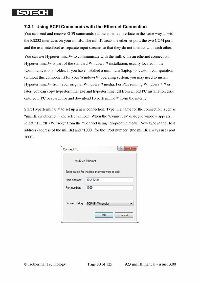
© Isothermal Technology Page 80 of 125 923 milliK manual - issue: 3.00
7.3.1 Using SCPI Commands with the Ethernet Connection
You can send and receive SCPI commands via the ethernet interface in the same way as with
the RS232 interfaces on your milliK. The milliK treats the ethernet port, the two COM ports
and the user interface) as separate input streams so that they do not interact with each other.
You can use Hyperterminal™ to communicate with the milliK via an ethernet connection.
Hyperterminal™ is part of the standard Windows™ installation, usually located in the
‘Communications’ folder. If you have installed a minimum (laptop) or custom configuration
(without this component) for your Windows™ operating system, you may need to install
Hyperterminal™ from your original Windows™ media. For PCs running Windows 7™ or
later, you can copy hyperterminal.exe and hyperterminel.dll from an old PC installation disk
onto your PC or search for and download Hyperterminal™ from the internet.
Start Hyperterminal™ to set up a new connection. Type in a name for the connection (such as
“milliK via ethernet”) and select an icon. When the ‘Connect to’ dialogue window appears,
select “TCP/IP (Winsoc)” from the “Connect using” drop-down menu. Now type in the Host
address (address of the milliK) and “1000” for the ‘Port number’ (the milliK always uses port
1000):
.
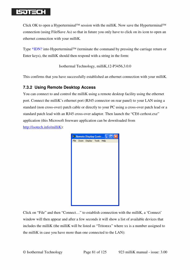
© Isothermal Technology Page 81 of 125 923 milliK manual - issue: 3.00
Click OK to open a Hyperterminal™ session with the milliK. Now save the Hyperterminal™
connection (using File|Save As) so that in future you only have to click on its icon to open an
ethernet connection with your milliK.
Type *IDN? into Hyperterminal™ (terminate the command by pressing the carriage return or
Enter keys), the milliK should then respond with a string in the form:
Isothermal Technology, milliK,12-P3456,3.0.0
This confirms that you have successfully established an ethernet connection with your milliK.
7.3.2 Using Remote Desktop Access
You can connect to and control the milliK using a remote desktop facility using the ethernet
port. Connect the milliK’s ethernet port (RJ45 connector on rear panel) to your LAN using a
standard (non cross-over) patch cable or directly to your PC using a cross-over patch lead or a
standard patch lead with an RJ45 cross-over adaptor. Then launch the “CE6 cerhost.exe”
application (this Microsoft freeware application can be downloaded from
http://isotech.info/milliK):
Click on “File” and then “Connect…” to establish connection with the milliK, a ‘Connect’
window will then appear and after a few seconds it will show a list of available devices that
includes the milliK (the milliK will be listed as “Tritonxx” where xx is a number assigned to
the milliK in case you have more than one connected to the LAN):
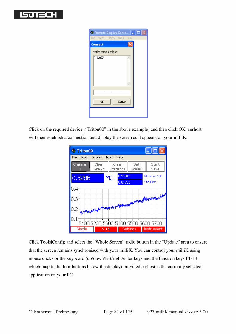
© Isothermal Technology Page 82 of 125 923 milliK manual - issue: 3.00
Click on the required device (“Triton00” in the above example) and then click OK, cerhost
will then establish a connection and display the screen as it appears on your milliK:
Click Tools|Config and select the “Whole Screen” radio button in the “Update” area to ensure
that the screen remains synchronised with your milliK. You can control your milliK using
mouse clicks or the keyboard (up/down/left/right/enter keys and the function keys F1-F4,
which map to the four buttons below the display) provided cerhost is the currently selected
application on your PC.
© Isothermal Technology Page 83 of 125 923 milliK manual - issue: 3.00
8 SCPI Command Set
The command format and protocol used by the milliK is based on the SCPI (Standard
Commands for Programmable Instruments) standard. This was developed to provide a
consistent command language for all types of programmable instruments. The objective was
to reduce the development time required by users of these instruments by providing a
consistent programming environment through the use of defined messages, instrument
responses and data formats. Further information on SCPI can be obtained from the SCPI
Consortium (http://www.scpiconsortium.org).
8.1 Command Terminators
SCPI commands are ASCII (American Standard Code for Information Interchange) character
strings and should be terminated with a Carriage Return character (ASCII character 13).
Responses from the milliK are always terminated by a Carriage Return character.
8.2 SCPI Command Structure
Commands are arranged in a hierarchical tree, similar to directory trees used in PCs. SCPI
uses a defined notation to represent the command tree structure. Each node in the tree
structure is a command keyword with keywords being separated by colons (:). To simplify
the description of the SCPI commands, the notation represents levels in the tree using
horizontal indentations with the root node being the left most column. For example, the
milliK includes the following command structure:
SENSe
:FUNCtion
:CHANnel
:RESistance
:RANGe
:RANGe?
READ?
CALibrate
:VOLTage:GAIN
:VOLTage:GAIN?
A valid command is formed by following the tree structure from a root node until a node is
reached with no further nodes below it, for example in the above command tree we may use:
SENSe:RESistance:RANGe
© Isothermal Technology Page 84 of 125 923 milliK manual - issue: 3.00
Keywords can be shortened to the first four letters (or 3 if the last letter is a vowel). To
indicate this, the notation uses upper-case to indicate required letters and lower-case to
indicate optional letters (NB: all commands are case-insensitive). For example, valid forms of
the above command include:
Sense:Resistance:Range
SENS:RES:RANG
Sense:resistance:RAnG
To shorten the commands, default (optional) keywords are enclosed in square brackets and
may be omitted. For example, in the case of the command:
MEASure[:SCALar]:VOLTage:[DC]?
Valid forms of this command include:
MEAS:VOLT?
MEASURE:SCALAR:VOLTAGE:DC?
8.3 SCPI Numeric Suffices
In order to support multiple input channels, commands can include numeric suffices. These
are represented by a hash (#) in the command notation, for example:
MEASure:VOLTage<channel#>?
In order to measure the voltage on channel 2, the command used would be:
MEAS:VOLT2?
8.4 Parameters
If a command requires parameter(s), these follow the command and are separated from it by a
space. If more than one parameter is required, each parameter is separated by a comma (,).
For example, the command to measure resistance on channel 1 using a range up to 100 ohm
at the normal 1mA sense current using a 4-wire technique is:
MEAS:RES1? 100,NORM,4
© Isothermal Technology Page 85 of 125 923 milliK manual - issue: 3.00
8.5 Units
Numeric parameters may optionally include units (if you omit units, the milliK assumes
appropriate default units). The only units required for milliK are ohms (which are indicated
by ‘R’, ‘r’, or OHM) and volts (indicated by ‘V’ or ‘v’).
The standard multiplying prefixes may also be used to indicate decimal multiples or fractions.
For example, the following are all equivalent:
CAL:VOLT:OFFS1 2E3uV
CAL:VOLT:OFFS1 2 (note: default units are mV)
CAL:VOLT:OFFS1 0.002V
The following prefixes are available:
prefix name factor
U or u micro 10-6
M or m milli 10-3 (cannot be used with ohms, see note below)
K or k kilo 10+3
Note: The SCPI standard does not permit the use of ‘M’ or ‘m’ as a prefix for ohms to
indicate milli-ohms since the M or MA prefix is used to indicate mega-ohms.
8.6 Making Measurements Using SCPI Commands
The milliK’s measurement system can be controlled by SCPI commands from the ethernet
port or either of the RS232 ports. The software makes no distinction between commands
received on any port and will process these in the order in which they are received. If a
response is expected, it will always be sent to the port on which the initiating command was
received.
There is no direct interference between measurements made using the front panel user
interface and measurements requested using SCPI commands. However, measurements take
some time to complete so there may be a delay in responses to SCPI commands if
measurements are being made via the front panel user interface. To avoid unnecessary delays
in responses to SCPI commands, you can stop all measurements requested via the front panel
user interface. To do this, send the SCPI command “REMote” on any port.
© Isothermal Technology Page 86 of 125 923 milliK manual - issue: 3.00
8.6.1 Measuring Resistance using SCPI Commands
In order to measure the resistance of a PRT, you need to:
select the measurement channel
set the milliK to measure resistance
select the measurement range
set the sense current (normal or root2 current)
select 3 or 4-wire measurement
initiate the measurement
collect the result
To use channel 1 to make a 4-wire resistance measurement on a 100Ω PRT up to a maximum
resistance of 200Ω using the normal (1mA) sense current, send the following command
sequence:
SENSe:CHANnel 1
SENSe:FUNCtion RESistance
SENSe:RESistance:RANGe 200
SENSe:CURRent NORMal
SENSe:WIRes 4
INITiate
FETCh?
The milliK will then report the measured resistance, for example “1.19986619E+002”. The
commands INIT and FETCH? can be replaced by the single command READ?. To repeat the
measurement using the same settings, send READ?. To make 10 measurements with the same
settings send READ? 10 (note: the milliK returns all 10 measurements in a burst at the end of
the measurement sequence).
The following command performs a single measurement with the same settings:
MEASure:RESistance1? 200,NORMal,4
8.6.2 Measuring Voltage (with optional RJC) using SCPI Commands
In order to measure the voltage from a thermocouple with (optional) reference junction
compensation (using the connector contact temperature determined by the milliK’s internal
reference junction sensor) the milliK must be in REMote mode (see section 8.6.7) and you
need to:
ensure the milliK is in REMote mode
select the measurement channel
set the milliK to measure voltage
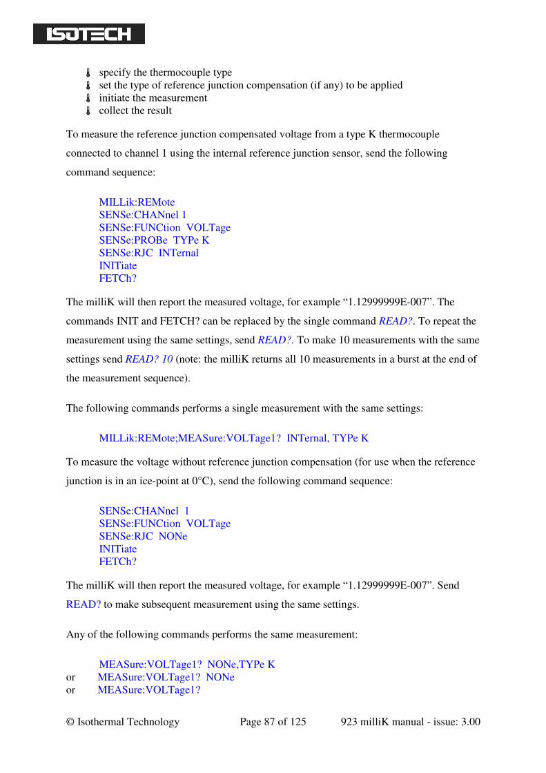
© Isothermal Technology Page 87 of 125 923 milliK manual - issue: 3.00
specify the thermocouple type
set the type of reference junction compensation (if any) to be applied
initiate the measurement
collect the result
To measure the reference junction compensated voltage from a type K thermocouple
connected to channel 1 using the internal reference junction sensor, send the following
command sequence:
MILLik:REMote
SENSe:CHANnel 1
SENSe:FUNCtion VOLTage
SENSe:PROBe TYPe K
SENSe:RJC INTernal
INITiate
FETCh?
The milliK will then report the measured voltage, for example “1.12999999E-007”. The
commands INIT and FETCH? can be replaced by the single command READ?. To repeat the
measurement using the same settings, send READ?. To make 10 measurements with the same
settings send READ? 10 (note: the milliK returns all 10 measurements in a burst at the end of
the measurement sequence).
The following commands performs a single measurement with the same settings:
MILLik:REMote;MEASure:VOLTage1? INTernal, TYPe K
To measure the voltage without reference junction compensation (for use when the reference
junction is in an ice-point at 0°C), send the following command sequence:
SENSe:CHANnel 1
SENSe:FUNCtion VOLTage
SENSe:RJC NONe
INITiate
FETCh?
The milliK will then report the measured voltage, for example “1.12999999E-007”. Send
READ? to make subsequent measurement using the same settings.
Any of the following commands performs the same measurement:
MEASure:VOLTage1? NONe,TYPe K
or MEASure:VOLTage1? NONe
or MEASure:VOLTage1?
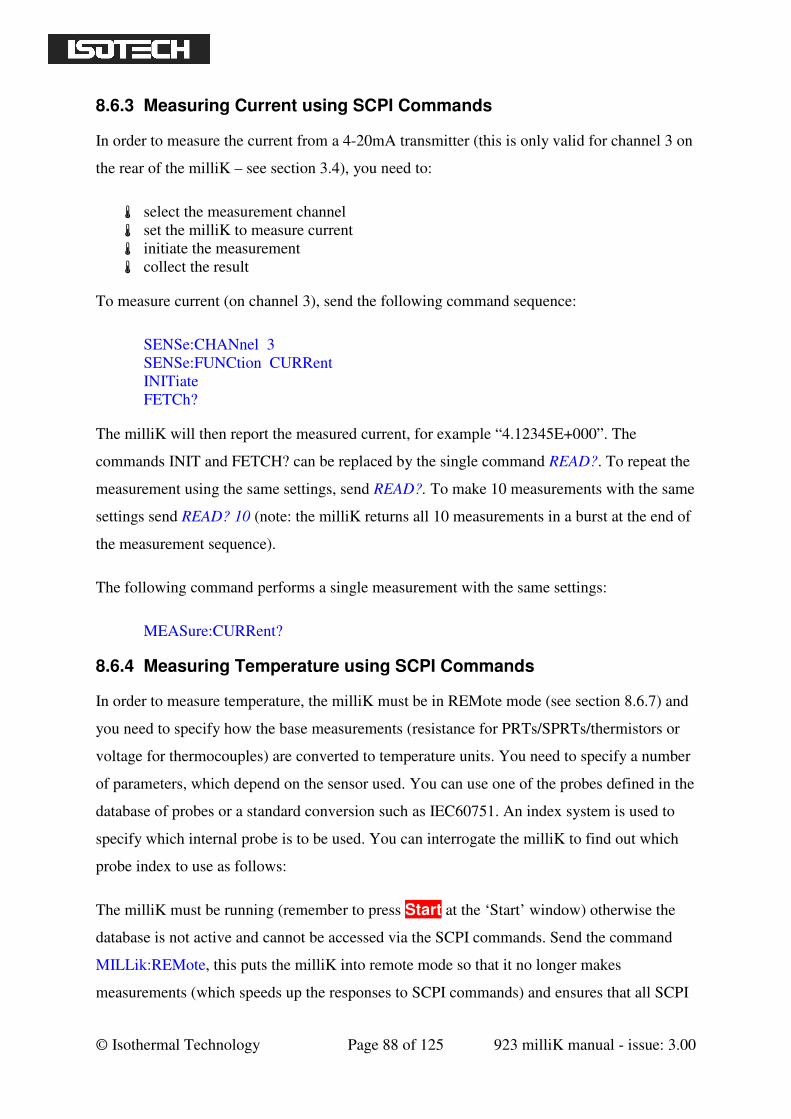
© Isothermal Technology Page 88 of 125 923 milliK manual - issue: 3.00
8.6.3 Measuring Current using SCPI Commands
In order to measure the current from a 4-20mA transmitter (this is only valid for channel 3 on
the rear of the milliK – see section 3.4), you need to:
select the measurement channel
set the milliK to measure current
initiate the measurement
collect the result
To measure current (on channel 3), send the following command sequence:
SENSe:CHANnel 3
SENSe:FUNCtion CURRent
INITiate
FETCh?
The milliK will then report the measured current, for example “4.12345E+000”. The
commands INIT and FETCH? can be replaced by the single command READ?. To repeat the
measurement using the same settings, send READ?. To make 10 measurements with the same
settings send READ? 10 (note: the milliK returns all 10 measurements in a burst at the end of
the measurement sequence).
The following command performs a single measurement with the same settings:
MEASure:CURRent?
8.6.4 Measuring Temperature using SCPI Commands
In order to measure temperature, the milliK must be in REMote mode (see section 8.6.7) and
you need to specify how the base measurements (resistance for PRTs/SPRTs/thermistors or
voltage for thermocouples) are converted to temperature units. You need to specify a number
of parameters, which depend on the sensor used. You can use one of the probes defined in the
database of probes or a standard conversion such as IEC60751. An index system is used to
specify which internal probe is to be used. You can interrogate the milliK to find out which
probe index to use as follows:
The milliK must be running (remember to press Start at the ‘Start’ window) otherwise the
database is not active and cannot be accessed via the SCPI commands. Send the command
MILLik:REMote, this puts the milliK into remote mode so that it no longer makes
measurements (which speeds up the responses to SCPI commands) and ensures that all SCPI
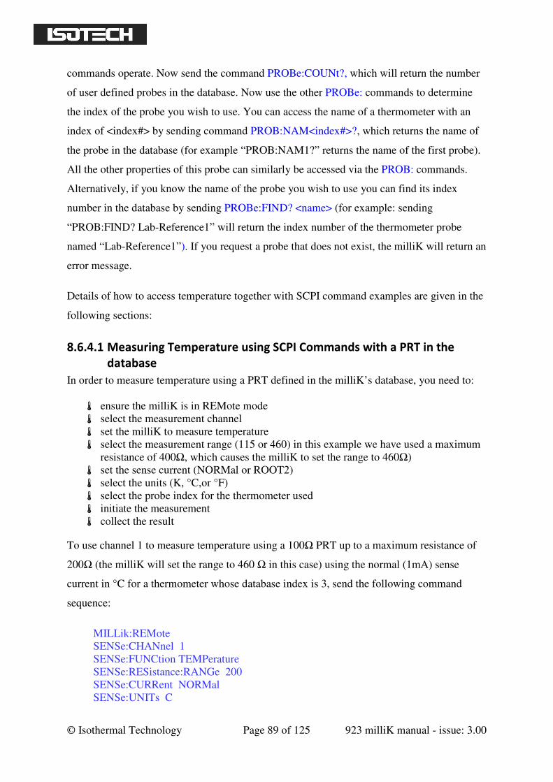
© Isothermal Technology Page 89 of 125 923 milliK manual - issue: 3.00
commands operate. Now send the command PROBe:COUNt?, which will return the number
of user defined probes in the database. Now use the other PROBe: commands to determine
the index of the probe you wish to use. You can access the name of a thermometer with an
index of <index#> by sending command PROB:NAM<index#>?, which returns the name of
the probe in the database (for example “PROB:NAM1?” returns the name of the first probe).
All the other properties of this probe can similarly be accessed via the PROB: commands.
Alternatively, if you know the name of the probe you wish to use you can find its index
number in the database by sending PROBe:FIND? <name> (for example: sending
“PROB:FIND? Lab-Reference1” will return the index number of the thermometer probe
named “Lab-Reference1”). If you request a probe that does not exist, the milliK will return an
error message.
Details of how to access temperature together with SCPI command examples are given in the
following sections:
8.6.4.1 Measuring Temperature using SCPI Commands with a PRT in the
database
In order to measure temperature using a PRT defined in the milliK’s database, you need to:
ensure the milliK is in REMote mode
select the measurement channel
set the milliK to measure temperature
select the measurement range (115 or 460) in this example we have used a maximum
resistance of 400Ω, which causes the milliK to set the range to 460Ω)
set the sense current (NORMal or ROOT2)
select the units (K, °C,or °F)
select the probe index for the thermometer used
initiate the measurement
collect the result
To use channel 1 to measure temperature using a 100Ω PRT up to a maximum resistance of
200Ω (the milliK will set the range to 460 Ω in this case) using the normal (1mA) sense
current in °C for a thermometer whose database index is 3, send the following command
sequence:
MILLik:REMote
SENSe:CHANnel 1
SENSe:FUNCtion TEMPerature
SENSe:RESistance:RANGe 200
SENSe:CURRent NORMal
SENSe:UNITs C
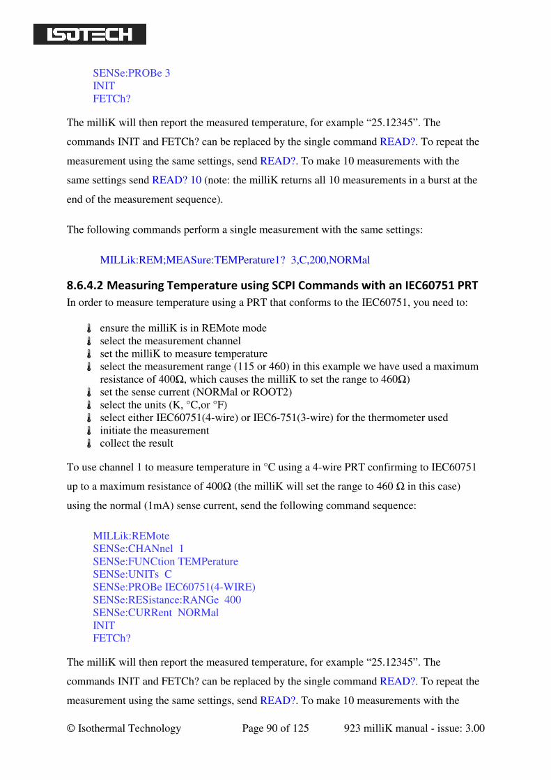
© Isothermal Technology Page 90 of 125 923 milliK manual - issue: 3.00
SENSe:PROBe 3
INIT
FETCh?
The milliK will then report the measured temperature, for example “25.12345”. The
commands INIT and FETCh? can be replaced by the single command READ?. To repeat the
measurement using the same settings, send READ?. To make 10 measurements with the
same settings send READ? 10 (note: the milliK returns all 10 measurements in a burst at the
end of the measurement sequence).
The following commands perform a single measurement with the same settings:
MILLik:REM;MEASure:TEMPerature1? 3,C,200,NORMal
8.6.4.2 Measuring Temperature using SCPI Commands with an IEC60751 PRT
In order to measure temperature using a PRT that conforms to the IEC60751, you need to:
ensure the milliK is in REMote mode
select the measurement channel
set the milliK to measure temperature
select the measurement range (115 or 460) in this example we have used a maximum
resistance of 400Ω, which causes the milliK to set the range to 460Ω)
set the sense current (NORMal or ROOT2)
select the units (K, °C,or °F)
select either IEC60751(4-wire) or IEC6-751(3-wire) for the thermometer used
initiate the measurement
collect the result
To use channel 1 to measure temperature in °C using a 4-wire PRT confirming to IEC60751
up to a maximum resistance of 400Ω (the milliK will set the range to 460 Ω in this case)
using the normal (1mA) sense current, send the following command sequence:
MILLik:REMote
SENSe:CHANnel 1
SENSe:FUNCtion TEMPerature
SENSe:UNITs C
SENSe:PROBe IEC60751(4-WIRE)
SENSe:RESistance:RANGe 400
SENSe:CURRent NORMal
INIT
FETCh?
The milliK will then report the measured temperature, for example “25.12345”. The
commands INIT and FETCh? can be replaced by the single command READ?. To repeat the
measurement using the same settings, send READ?. To make 10 measurements with the
© Isothermal Technology Page 91 of 125 923 milliK manual - issue: 3.00
same settings send READ? 10 (note: the milliK returns all 10 measurements in a burst at the
end of the measurement sequence).
The following commands perform a single measurement with the same settings:
MILLik:REM;MEASure:TEMPerature1? IEC60751(4-WIRE),C,400,NORMal
8.6.4.3 Measuring Temperature using SCPI Commands with a Thermocouple
in the database
In order to measure temperature using a thermocouple defined in the milliK’s database, you
need to:
ensure the milliK is in REMote mode
select the measurement channel
set the milliK to measure temperature
select the units (K, °C,or °F)
select the probe index for the thermometer used
select the reference junction compensation to be used (NONe or INTernal))
initiate the measurement
collect the result
To use channel 2 to measure temperature in °C using a thermocouple in the database whose
database index is 5 using internal reference junction compensation, send the following
command sequence:
MILLik:REMote
SENSe:CHANnel 2
SENSe:FUNCtion TEMPerature
SENSe:UNITs C
SENSe:PROBe 5
SENSe:RJC INTernal
INIT
FETCh?
The milliK will then report the measured temperature, for example “21.23456”. The
commands INIT and FETCh? can be replaced by the single command READ?. To repeat the
measurement using the same settings, send READ?. To make 10 measurements with the
same settings send READ? 10 (note: the milliK returns all 10 measurements in a burst at the
end of the measurement sequence).
The following commands perform a single measurement with the same settings:
MILLik:REM;MEASure:TEMPerature2? 5,C,INTernal
© Isothermal Technology Page 92 of 125 923 milliK manual - issue: 3.00
8.6.4.4 Measuring Temperature using SCPI Commands with an IEC584 Typed
Thermocouple
In order to measure temperature using a thermocouple that conforms to one of the “types”
defined in standard IEC584, you need to:
ensure the milliK is in REMote mode
select the measurement channel
set the milliK to measure temperature
select the units (K, °C,or °F)
select the reference junction compensation to be used (NONe or INTernal))
select the type of thermocouple used
initiate the measurement
collect the result
To use channel 2 to measure temperature in °C using a type K thermocouple using no
reference junction compensation (ice point reference junction), send the following command
sequence:
MILLik:REMote
SENSe:CHANnel 2
SENSe:FUNCtion TEMPerature
SENSe:UNITs C
SENSe:PROBe TYPe K
SENSe:RJC NONe
INIT
FETCh?
The milliK will then report the measured temperature, for example “20.12345”. The
commands INIT and FETCh? can be replaced by the single command READ?. To repeat the
measurement using the same settings, send READ?. To make 10 measurements with the
same settings send READ? 10 (note: the milliK returns all 10 measurements in a burst at the
end of the measurement sequence).
The following commands perform a single measurement with the same settings:
MILLik:REM;MEASure:TEMPerature2? TYPe K,C,NONe
8.6.4.5 Measuring Temperature using SCPI Commands with a Thermistor in
the database
In order to measure temperature using a thermistor defined in the milliK’s database, you need
to:
© Isothermal Technology Page 93 of 125 923 milliK manual - issue: 3.00
ensure the milliK is in REMote mode
select the measurement channel
set the milliK to measure temperature
select the units (K, °C,or °F)
select the probe index for the thermometer used
initiate the measurement
collect the result
To use channel 1 to measure temperature in °C using a thermistor in the database whose
database index is 6, send the following command sequence:
MILLik:REMote
SENSe:CHANNel 1
SENSe:FUNCtion TEMPerature
SENSe:UNITs C
SENSe:PROBe 6
INIT
FETCh?
The milliK will then report the measured temperature, for example “20.12345”. The
commands INIT and FETCh? can be replaced by the single command READ?. To repeat the
measurement using the same settings, send READ?. To make 10 measurements with the
same settings send READ? 10 (note: the milliK returns all 10 measurements in a burst at the
end of the measurement sequence).
The following commands perform a single measurement with the same settings:
MILLik:REM;MEASure:TEMPerature1? 6,C
8.6.4.6 Measuring Temperature using SCPI Commands with a 4-20mA
Transmitter in the database
In order to measure temperature using a 4-20mA transmitter defined in the milliK’s database,
you need to:
ensure the milliK is in REMote mode
select the measurement channel (this must be channel 3)
set the milliK to measure temperature
select the units (K, °C,or °F)
select the probe index for the thermometer used
initiate the measurement
collect the result
© Isothermal Technology Page 94 of 125 923 milliK manual - issue: 3.00
To use channel 3 to measure temperature in °F using a 4-20mA transmitter in the database
whose database index is 9, send the following command sequence:
MILLik:REMote
SENSe:CHANNel 3
SENSe:FUNCtion TEMPerature
SENSe:UNITs F
SENSe:PROBe 9
INIT
FETCh?
The milliK will then report the measured temperature, for example “20.12345”. The
commands INIT and FETCh? can be replaced by the single command READ?. To repeat the
measurement using the same settings, send READ?. To make 10 measurements with the
same settings send READ? 10 (note: the milliK returns all 10 measurements in a burst at the
end of the measurement sequence).
The following commands perform a single measurement with the same settings:
MILLik:REM;MEASure:TEMPerature3? 9,C
8.6.5 SCPI Commands
The milliK supports the following commands:
*IDN?
REMote
LOCal
SENSe
:FUNCtion[:ON] <function>
:FUNCtion[:ON]?
:CHANnel <channel>
:CHANnel?
[:RESistance]
:RANGe[:UPPer] <range>
:RANGe[:UPPer]?
:WIRes <wires>
:WIRes?
:CURRent <current>
:CURRent?
:PROBe <probe>
:PROBe?
:UNITs <units>
:UNITs?
:RJC
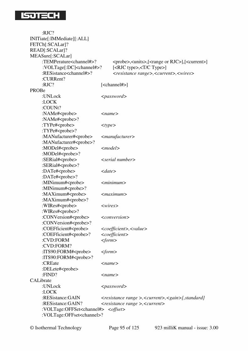
© Isothermal Technology Page 95 of 125 923 milliK manual - issue: 3.00
:RJC?
INITiate[:IMMediate][:ALL]
FETCh[:SCALar]?
READ[:SCALar]?
MEASure[:SCALar]
:TEMPerature<channel#>? <probe>,<units>,[<range or RJC>],[<current>]
:VOLTage[:DC]<channel#>? [<RJC type>,<T/C Type>]
:RESistance<channel#>? <resistance range>,<current>,<wires>
:CURRent?
:RJC? [<channel#>]
PROBe
:UNL ock <password>
:LOCK
:COUNt?
:NAMe#<probe> <name>
:NAMe#<probe>?
:TYPe#<probe> <type>
:TYPe#<probe>?
:MANufacturer#<probe> <manufacturer>
:MANufacturer#<probe>?
:MODel#<probe> <model>
:MODel#<probe>?
:SERial#<probe> <serial number>
:SERial#<probe>?
:DATe#<probe> <date>
:DATe#<probe>?
:MINimum#<probe> <minimum>
:MINimum#<probe>?
:MAXimum#<probe> <maximum>
:MAXimum#<probe>?
:WIRes#<probe> <wires>
:WIRes#<probe>?
:CONVersion#<probe> <conversion>
:CONVersion#<probe>?
:COEFficient#<probe> <coefficient>,<value>
:COEFficient#<probe>? <coefficient>
:CVD:FORM <form>
:CVD:FORM?
:ITS90:FORM#<probe> <form>
:ITS90:FORM#<probe>?
:CREate <name>
:DELete#<probe>
:FIND? <name>
CALibrate
:UNLock <password>
:LOCK
:RESistance:GAIN <resistance range >,<current>,<gain>[,standard]
:RESistance:GAIN? <resistance range >,<current>
:VOLTage:OFFSet<channel#> <offset>
:VOLTage:OFFset<channel>?
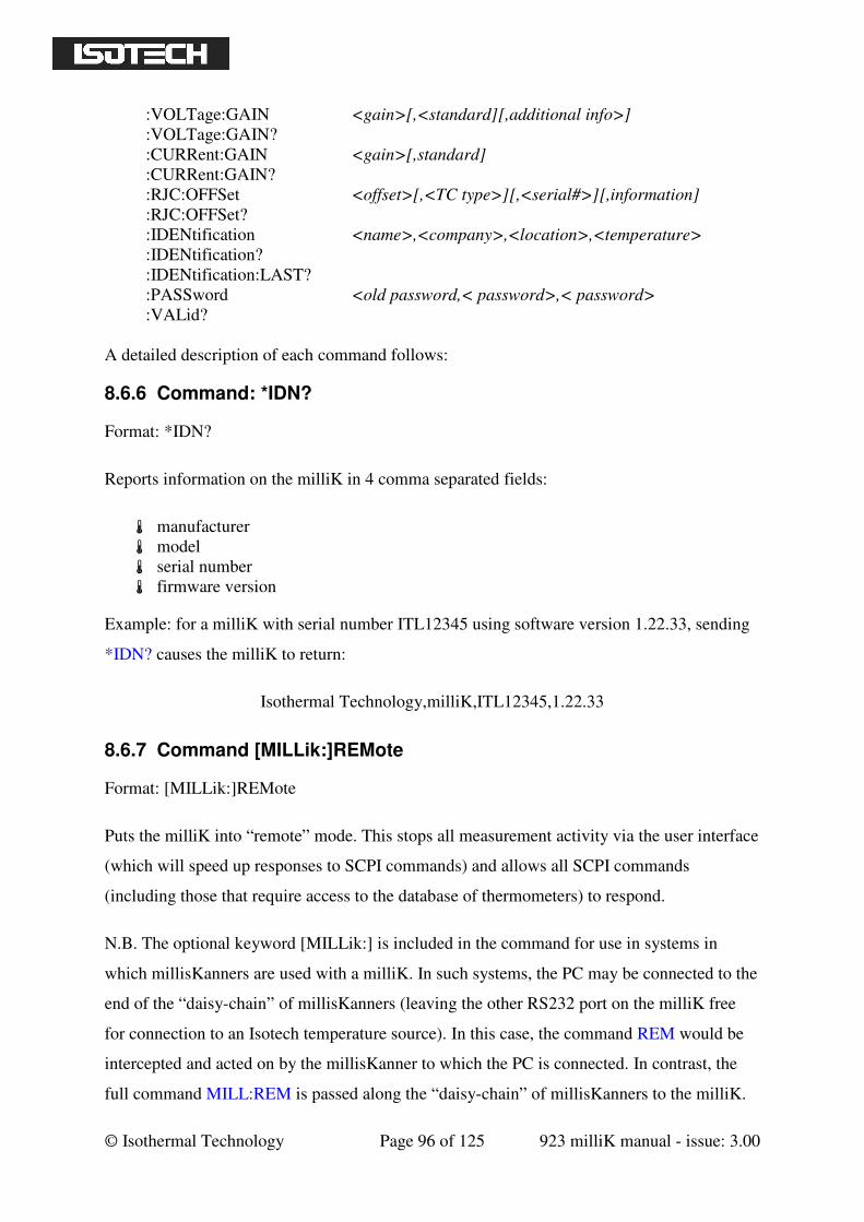
© Isothermal Technology Page 96 of 125 923 milliK manual - issue: 3.00
:VOLTage:GAIN <gain>[,<standard][,additional info>]
:VOLTage:GAIN?
:CURRent:GAIN <gain>[,standard]
:CURRent:GAIN?
:RJC:OFFSet <offset>[,<TC type>][,<serial#>][,information]
:RJC:OFFSet?
:IDENtification <name>,<company>,<location>,<temperature>
:IDENtification?
:IDENtification:LAST?
:PASSword <old password,< password>,< password>
:VALid?
A detailed description of each command follows:
8.6.6 Command: *IDN?
Format: *IDN?
Reports information on the milliK in 4 comma separated fields:
manufacturer
model
serial number
firmware version
Example: for a milliK with serial number ITL12345 using software version 1.22.33, sending
*IDN? causes the milliK to return:
Isothermal Technology,milliK,ITL12345,1.22.33
8.6.7 Command [MILLik:]REMote
Format: [MILLik:]REMote
Puts the milliK into “remote” mode. This stops all measurement activity via the user interface
(which will speed up responses to SCPI commands) and allows all SCPI commands
(including those that require access to the database of thermometers) to respond.
N.B. The optional keyword [MILLik:] is included in the command for use in systems in
which millisKanners are used with a milliK. In such systems, the PC may be connected to the
end of the “daisy-chain” of millisKanners (leaving the other RS232 port on the milliK free
for connection to an Isotech temperature source). In this case, the command REM would be
intercepted and acted on by the millisKanner to which the PC is connected. In contrast, the
full command MILL:REM is passed along the “daisy-chain” of millisKanners to the milliK.
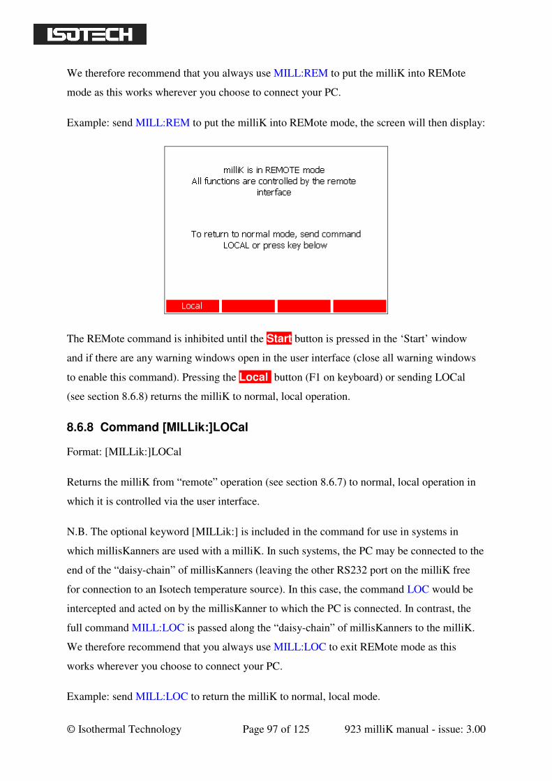
© Isothermal Technology Page 97 of 125 923 milliK manual - issue: 3.00
We therefore recommend that you always use MILL:REM to put the milliK into REMote
mode as this works wherever you choose to connect your PC.
Example: send MILL:REM to put the milliK into REMote mode, the screen will then display:
The REMote command is inhibited until the Start button is pressed in the ‘Start’ window
and if there are any warning windows open in the user interface (close all warning windows
to enable this command). Pressing the Local button (F1 on keyboard) or sending LOCal
(see section 8.6.8) returns the milliK to normal, local operation.
8.6.8 Command [MILLik:]LOCal
Format: [MILLik:]LOCal
Returns the milliK from “remote” operation (see section 8.6.7) to normal, local operation in
which it is controlled via the user interface.
N.B. The optional keyword [MILLik:] is included in the command for use in systems in
which millisKanners are used with a milliK. In such systems, the PC may be connected to the
end of the “daisy-chain” of millisKanners (leaving the other RS232 port on the milliK free
for connection to an Isotech temperature source). In this case, the command LOC would be
intercepted and acted on by the millisKanner to which the PC is connected. In contrast, the
full command MILL:LOC is passed along the “daisy-chain” of millisKanners to the milliK.
We therefore recommend that you always use MILL:LOC to exit REMote mode as this
works wherever you choose to connect your PC.
Example: send MILL:LOC to return the milliK to normal, local mode.
© Isothermal Technology Page 98 of 125 923 milliK manual - issue: 3.00
8.6.9 Command SENSe:FUNCtion[:ON]
Format: SENSe:FUNCtion[:ON] <function>
Selects the measurement function. The parameter <function> must be one of the following
valid SCPI parameters:
TEMPerature
RESistance
VOLTage[:DC]
CURRent
Example: send SENS:FUNC TEMP to set the milliK to measure temperature.
8.6.10 Command SENSe:FUNCtion[:ON]?
Format: SENSe:FUNCtion?
Reports the present measurement function (TEMPERATURE, RESISTANCE, VOLTAGE or
CURRENT).
Example: a milliK set to measure voltage will respond to SENS:FUNC? with “VOLTAGE”.
8.6.11 Command SENSe:CHANnel
Format: SENSe:CHANnel <channel>
Selects the channel for the next measurement. The channels on the front panel are numbered
1 and 2. The 4-20mA input on the rear panel is numbered 3. The channel is not actually
connected to the measurement system until a measurement is started using either the INITiate
or READ? commands.
Example: send SENS:CHAN 2 to select channel 2 for the next measurement.
8.6.12 Command SENSe:CHANnel?
Format: SENSe:CHANnel?
Reports the channel selected for the next measurement. The channels on the front panel are
numbered 1 and 2. The 4-20mA input on the rear panel is numbered 3.
© Isothermal Technology Page 99 of 125 923 milliK manual - issue: 3.00
Example: a milliK set to measure channel 1 on the next measurement will respond to
SENS:CHAN? by returning “1”.
8.6.13 Command SENSe[:RESistance]:RANGe[:UPPer]
Format: SENSe[:RESistance]:RANGe[:UPPer] < range>
Sets the <range> for the next resistance measurement. The 3 resistance ranges available on
the milliK are:
resistance range = 0 - 115Ω
resistance range = 0 - 460Ω
resistance range = 0 - 500kΩ
The resistance range specified should be the highest resistance expected for the thermometer.
Example: send SENS:RANG 390 to set the milliK to measure a PRT that has a resistance of
390Ω at its highest operating temperature. The milliK will then set the range to 0-460 Ω since
this is the most sensitive range that can accommodate the requested maximum resistance.
8.6.14 Command SENSe[:RESistance:]RANGe[:UPPer]?
Format: SENSe[:RESistance]:RANGe[:UPPer]?
Reports the range for the next resistance measurement.
Example: a milliK that has had its resistance range set to 0-460Ω by sending SENS:RANG
390 (see section 8.6.13) would respond to the command SENS:RANG? by returning “460”.
8.6.15 Command SENSe:RESistance:WIRes
Format: SENSe:RESistance:WIRes <wires>
Determines whether the next resistance measurement on a PRT/SPRT will be made using 3
or 4-wire resistance measurement technique (see section 3.1.3 for details on 3 and 4-wire
measurements). The parameter <wires> must be 3 or 4, otherwise the command will be
ignored and an error message will be returned.
Example: send: SENS:RES:WIR 3 to select 3-wire measurement for the next resistance
measurement.
© Isothermal Technology Page 100 of 125 923 milliK manual - issue: 3.00
Note: This parameter is not required (and is ignored) when making a temperature
measurement using a PRT since the 3 or 4 wire setting is defined either in the database for the
selected thermometer or when the generic thermometer is specified (using “IEC60751(3-
wire)” or IEC60751(4-wire)”).
8.6.16 Command SENSe:RESistance:WIRes?
Format: SENSe:RESistance:WIRes?
Reports whether 3 or 4-wire measurement is selected for the next resistance measurement on
a PRT/SPRT.
Example: a milliK that has been set to make a 4-wire resistance measurement will respond to
the command SENS:RES:WIR? by returning “4”.
8.6.17 Command SENSe:CURRent
Format: SENSe:CURRent <current>
Determines whether the normal (1mA) or root2 (1.428mA) current is used for the next
resistance measurement on a PRT/SPRT. Changing the current to root2 allows the self-
heating effect to be determined for a PRT/SPRT (see section 3.1.2 for details). This command
affects the sense current used to measure PRTs/SPRTs (0-115Ω and 0-460Ω ranges), it does
not affect the sense current used to measured thermistors (fixed at 2µA). The current is not
changed until a measurement is started using with either the INITiate or READ? commands.
The parameter <current> may be NORMal or ROOT2, the command will be ignored and an
error message returned if any other parameter is used.
Example: send SENS:CURR NORM to set the sense current for the next resistance
measurement to the normal current (1mA).
8.6.18 Command SENSe:CURRent?
Format: SENSe:CURRent?
Reports the current that will be used for the next resistance measurement.
Example: a milliK that has been set to normal current and one of the PRT ranges (0-115 Ω or
0-460Ω) will respond to the command SENS:CURR? with: “1.00000E-003” (i.e. 1mA).
© Isothermal Technology Page 101 of 125 923 milliK manual - issue: 3.00
8.6.19 Command SENSe:PROBe
Format: SENSe:PROBe <probe>
Specifies the thermometer probe to be used in the next a measurement of temperature (see
sections 8.6.4.1 to 8.6.4.6), <probe> can be either an index to a thermometer in the milliK’s
database or a standard thermometer type, such as:
NONe
IEC60751(3-WIRE)
IEC60751(4-WIRE)
TYPe B
TYPe E
TYPe J
TYPe K
TYPe L
TYPe N
TYPe R
TYPe S
TYPe T
TYPe AU-PT
TYPe PT-PD
Examples: send SENS:PROB 2 to select the second probe in the milliK’s database for use in
a temperature measurement. Send SENS:PROB TYP K To select a type K thermocouple for
use in a temperature measurement.
8.6.20 Command SENSe:PROBe?
Format: SENSe:PROBe?
Reports the thermometer probe to be used in the next a measurement of temperature (see
sections 8.6.4.1 to 8.6.4.6). this will be either an index to a thermometer in the milliK’s
database or a standard thermometer type (see section 8.6.19).
Example: a milliK set to measure temperature using a type N thermometer will respond to the
command SENS:PROB? by returning “Type N”.
8.6.21 Command SENSe:INITs
Format: SENSe:UNITs <units>
Specifies the units (Kelvin, Celsius or Fahrenheit) for subsequent temperature measurements.
The parameter <units> must be one of the following: K, C or F.
© Isothermal Technology Page 102 of 125 923 milliK manual - issue: 3.00
Example: send SENS:UNIT C To select temperature measurements in degrees Celsius.
8.6.22 Command SENSe:UNITs?
Format: SENSe:UNITs?
Reports the units (K, C or F) used for temperature measurements.
Example: a milliK set to measure temperature in °C will respond to the command
SENS:UNIT? by returning “C”.
8.6.23 Command SENSe:RJC
Format: SENSe:RJC <rjc>
Specifies the type of reference junction compensation used in making subsequent temperature
or voltage measurements made with any thermocouple. The parameter <rjc> must be one of
the following SCPI parameters: NONe or INTernal.
Example: send SENS:RJC INT to select internal reference junction compensation (using the
milliK’s internal reference junction sensor) for measurements with thermocouples.
8.6.24 Command SENSe:RJC?
Format: SENSe:RJC?
Reports the type of reference junction compensation used in making temperature or voltage
measurements with thermocouple.
Example: a milliK set to use internal reference junction compensation with thermocouples
will respond to the command SENS:RJC? by returning “Internal”.
8.6.25 Command INITiate[:IMMediate][:ALL]
Format: INITiate[:IMMediate][:ALL]
Initiates a measurement using the conditions defined by previous SENSe commands. The
measurement is made immediately, but not reported.
Example: send INIT to initiate a (voltage) measurement that has been defined with SENSe
commands (such as SENS:CHAN 1 ; SENS:FUNC volt ; SENS:RJC None ; SENS:PROB
NONe).
© Isothermal Technology Page 103 of 125 923 milliK manual - issue: 3.00
8.6.26 Command FETCh[:SCALar]?
Format: FETCh[:SCALar]?
Reports the result of the last measurement made.
Example: a milliK that has made a measurement on channel 1 using the commands shown in
the example in section 8.6.25 will respond to FETC? with a value in the form: “0.00154514”.
8.6.27 Command READ[:SCALar]?
Format: READ[:SCALar]? [<readings>]
Initiates and reports a measurement using the conditions defined by previous SENSe
commands. This is equivalent to INIT followed by FETCh?. The optional parameter
following READ? specifies the number of times the measurement is to be repeated. The
command makes all the measurements and then returns them in one burst at the end of the
sequence (rather than as they are made).
Example: a milliK that has been configured to make a voltage measurement using SENSe
commands (such as SENS:CHAN 1 ; SENS:FUNC volt ; SENS:RJC None ; SENS:PROB
NONe) will respond to READ? with a value in the form: “0.00154514”.
8.6.28 Command MEASure[:SCALar]:TEMPerature<channel#>?
Format: MEASure[:SCALar]:TEMPerature [:DC]<channel#>? <probe>,<units>[,<Range
or RJC>,<Current>]
Initiates and reports a measurement of temperature on <channel#> (note that there is no gap
between the command and the channel number as this command makes use of the numeric
suffices feature of SCPI described in section 8.3) using thermometer <probe> in units of
<units>. The parameter <probe> can be either an index to a thermometer in the milliK’s
database or a standard thermometer type, such as:
NONe
IEC60751(3-WIRE)
IEC60751(4-WIRE)
TYPe B
TYPe E
TYPe J
TYPe K
TYPe L
© Isothermal Technology Page 104 of 125 923 milliK manual - issue: 3.00
TYPe N
TYPe R
TYPe S
TYPe T
TYPe AU-PT
TYPe PT-PD
Parameters 3 and 4 after the command depend on the type of thermometer. For PRTs,
parameter 3 specifies the maximum resistance of the thermometer used and the sense current
to be used (NORMal or ROOT2 for 1mA and 1.428mA). For thermocouples, parameter 3
specifies what reference junction compensation is to be used for both temperature and voltage
measurements and parameter 4 is not used. For thermistors, parameters 3 and 4 are not used.
Examples:
Send MEAS:TEMP1? 3,C,200,Normal to use channel 1 to measure temperature in °C with
the third thermometer (a PRT) in the database, up to a maximum resistance of 200Ω with
normal (1mA) sense current.
Send MEAS:TEMP1? IEC60751(4-wire),C,400,NORM to use channel 1 to measure
temperature in °C with an 4-wire PRT that confirms to standard IEC60751(2008), up to a
maximum resistance of 400Ω with normal (1mA) sense current.
Send MEAS:TEMP2? 5,F,INT to use channel 2 to measure temperature in °F with the fifth
thermometer (a thermocouple) in the database using internal reference junction
compensation.
Send MEAS:TEMP2? TYPE N,F,NON to use channel 2 to measure temperature in °F with
the type N thermocouple using no reference junction compensation.
To repeat the measurement using the same settings send READ? or INIT;FETCh?
8.6.29 Command MEASure[:SCALar]:VOLTage[:DC]<channel#>?
Format: MEASure[:SCALar]:VOLTage[:DC]<channel#>? [<RJC>,<Thermocouple Type>]
Initiates and reports a voltage measurement on <channel#> (note that there is no gap between
the command and the channel number as this command makes use of the numeric suffices
feature of SCPI described in section 8.3). The reported value is in volts. The optional
parameters (<RJC> and <Thermocouple Type>) provide the facility to apply reference
© Isothermal Technology Page 105 of 125 923 milliK manual - issue: 3.00
junction compensation to the measured voltage. If these parameters are absent, no
compensation is applied and the reference junction is then assumed to be 0°C.
This command is equivalent to SENSe:FUNCtion VOLTage, SENSe:CHANnel <channel>,
SENSe:RJC <RJC>, SENSe:PROBe <Thermocouple Type> and READ?
Examples:
Send MEAS:VOLT2? to use channel 2 to measure the voltage from a thermocouple (without
any reference junction compensation).
Send MEAS:VOLT2? Int,Type J to use channel 2 to measure the voltage and apply reference
junction compensation for a type J thermocouple using the milliK’s internal reference
junction temperature sensor.
8.6.30 Command MEASure[:SCALar]:RESistance<channel#>
Format: MEASure[:SCALar]:RESistance<channel#>? < range>,<current>,<wires>
Initiates and reports a resistance measurement on <channel#> using resistance < range> with
sense <current> and 3 or 4 wires measurement defined by <wires> (note that there is no gap
between the command and the channel number as this command makes use of the numeric
suffices feature of SCPI described in section 8.3). The reported value is in ohms. This
command is equivalent to SENS:FUNC RES, SENS:CHAN <channel>, SENS:RES:RANG
< range>, SENS:WIR <wires> and READ?
Example: send MEAS:RES1? 390,root2,4 to measure the resistance of a PRT on channel 1
that has a maximum operating resistance of 390Ω with root2 sense current using a 4-wire
technique.
8.6.31 Command MEASure[:SCALar]:CURRent?
Format: MEASure[:SCALar]:CURRent?
Initiates and reports a current measurement on channel 3 (4-20mA input on rear panel). The
reported value is in milli-amps. This command is equivalent to SENS:FUNC CURR,
SENS:CHAN 3, and READ?
Example: send MEAS:CURR? to make a current measurement on channel 3.
© Isothermal Technology Page 106 of 125 923 milliK manual - issue: 3.00
8.6.32 Command MEASure[:SCALar]:RJC?
Format: MEASure[:SCALar]:RJC? <channel>
Initiates and reports a measurement of the internal reference junction temperature (used with
thermocouples for reference junction compensation) of the specified <channel>. The
reported value is in °C. If the specified channel does not exist, the milliK returns “channel not
found”.
Example: send MEAS:RJC? 1 to measure the temperature of channel 1’s thermocouple
reference junction.
8.6.33 Command PROBe:UNLock
Format: PROBe:UNLock <password>
Unlocks the probe database to allow thermometer entries to be created, edited and deleted.
Example: send PROB:UNL 1234 to unlock the probe database (with the factory default
password).
8.6.34 Command PROBe:LOCK
Format: PROBe:LOCK
Locks the probe database to prevent thermometer entries being created, edited and deleted.
Example: send PROB:LOCK to lock the probe database.
8.6.35 Command PROBe:COUNt?
Format: PROBe:COUNt?
Returns the number of thermometer probes in the database.
Example: send PROB:COUN? to request the number of probes in the database.
8.6.36 Command PROBe:NAMe<probe#>
Format: PROBe:NAMe<probe#> <name>
Sets the ‘Name’ field in the database for probe index <probe#> to <name>.
© Isothermal Technology Page 107 of 125 923 milliK manual - issue: 3.00
Example: send PROB:NAM3 my third probe to set the ‘Name’ field of the third probe in the
database to “my third probe”.
8.6.37 Command PROBe:NAMe<probe#>?
Format: PROBe:NAMe<probe#>?
Returns the ‘Name’ field in the database for probe index <probe#>.
Example: send PROB:NAM4? to request the ‘Name’ of the fourth probe in the database.
8.6.38 Command PROBe:TYPe<probe#>
Format: PROBe:TYPe<probe#> <type>
Sets the ‘Type’ field in the database for probe index <probe#> to <type>. The parameter
<type> must be one of:
PRT
THERMOcouple
THERMistor
4-20MA
Example: send PROB:TYP3 PRT to set the ‘Type’ field of the third probe in the database to
‘PRT’.
8.6.39 Command PROBe:TYPe<probe#>?
Format: PROBe:TYPe<probe#>?
Returns the ‘Type’ field in the database for probe index <probe#>. The returned string will be
“PRT”, “Thermocouple”, “Thermistor” or “4-20mA”.
Example: send PROB:TYP4? to request the ‘Type’ of the fourth probe in the database.
8.6.40 Command PROBe:MANufacturer<probe#>
Format: PROBe:MANufacturer<probe#> <manufacturer>
Sets the ‘Manufacturer’ field in the database for probe index <probe#> to <manufacturer>.
© Isothermal Technology Page 108 of 125 923 milliK manual - issue: 3.00
Example: send PROB:MAN3 Isothermal Technology to set the ‘Manufacturer’ field of the
third probe in the database to “Isothermal Technology”.
8.6.41 Command PROBe:MANufacturer<probe#>?
Format: PROBe:MANufacturer<probe#>?
Returns the ‘Manufacturer’ field in the database for probe index <probe#>.
Example: send PROB:MAN4? to request the ‘Manufacturer’ of the fourth probe in the
database.
8.6.42 Command PROBe:MODel<probe#>
Format: PROBe: MODel<probe#> <model>
Sets the ‘Model’ field in the database for probe index <probe#> to <model>.
Example: send PROB:MODE3 96178 to set the ‘Model’ field of the third probe in the
database to “96178”.
8.6.43 Command PROBe:MODel<probe#>?
Format: PROBe:MODel<probe#>?
Returns the ‘Model’ field in the database for probe index <probe#>.
Example: send PROB:MOD4? to request the ‘Model’ of the fourth probe in the database.
8.6.44 Command PROBe:SERial<probe#>
Format: PROBe:SERial<probe#> <serial number>
Sets the ‘Serial Number’ field in the database for probe index <probe#> to <serial number>.
Example: send PROB:SER3 35583 to set the ‘Serial Number’ field of the third probe in the
database to “35583”.
8.6.45 Command PROBe:SERial<probe#>?
Format: PROBe:SERial<probe#>?
© Isothermal Technology Page 109 of 125 923 milliK manual - issue: 3.00
Returns the ‘Serial Number’ field in the database for probe index <probe#>.
Example: send PROB:SER4? to request the ‘Serial Number’ of the fourth probe in the
database.
8.6.46 Command PROBe:DATe<probe#>
Format: PROBe:DATe<probe#> <date>
Sets the ‘Re-calibration Date’ field in the database for probe index <probe#> to <date >. The
format of the date must be “dd/mm/yyyy” (leading zeros in the day or month may be
omitted).
Example: send PROB:DAT3 21/4/2020 to set the ‘Re-calibration Date’ field of the third
probe in the database to “21/04/2020” (25th April 2020).
8.6.47 Command PROBe:DATe<probe#>?
Format: PROBe:DATe<probe#>?
Returns the ‘Re-calibration Date’ field in the database for probe index <probe#>. The format
is always “dd/mm/yyyy”.
Example: send PROB:DAT4? to request the ‘Re-calibration Date’ of the fourth probe in the
database.
8.6.48 Command PROBe:MINimum<probe#>
Format: PROBe:MINimum<probe#> <minimum>
Sets the ‘Min Temperature’ field in the database for probe index <probe#> to <minimum >,
where the temperature units are °C.
Example: send PROB:MIN3 -40 to set the ‘Min Temperature’ field of the third probe in the
database to -40°C.
8.6.49 Command PROBe:MINimum<probe#>?
Format: PROBe:MINimum<probe#>?
© Isothermal Technology Page 110 of 125 923 milliK manual - issue: 3.00
Returns the ‘Min Temperature’ field in the database for probe index <probe#>. The
temperature units are °C.
Example: send PROB:MIN4? to request the ‘Min Temperature’ field of the fourth probe in
the database.
8.6.50 Command PROBe:MAXimum<probe#>
Format: PROBe:MAXimum<probe#> <maximum>
Sets the ‘Max Temperature’ field in the database for probe index <probe#> to <maximum >,
where the temperature units are °C.
Example: send PROB:MAX3 -40 to set the ‘Max Temperature’ field of the third probe in the
database to -40°C.
8.6.51 Command PROBe:MAXimum<probe#>?
Format: PROBe:MAXimum<probe#>?
Returns the ‘Max Temperature’ field in the database for probe index <probe#>. The
temperature units are °C.
Example: send PROB:MAX4? to request the ‘Max Temperature’ field of the fourth probe in
the database.
8.6.52 Command PROBe:WIRes<probe#>
Format: PROBe:WIRes<probe#> <wires>
Sets the ‘Wires’ field in the database for probe index <probe#> to <wires >, where wires
must be either 3 or 4. This field only applies to PRTs and the “Type” field for the
thermometer must be set to ‘PRT’ (using PROB:TYP<probe#> PRT) before using this
command (otherwise an error will be reported).
Example: send PROB:WIR3 4 to set the ‘Wires’ field of the third probe in the database
(must be a PRT) to 4.
© Isothermal Technology Page 111 of 125 923 milliK manual - issue: 3.00
8.6.53 Command PROBe:WIRes<probe#>?
Format: PROBe:WIRes<probe#>?
Returns the ‘Wires’ field in the database for probe index <probe#>. The returned value will
be 3, 4 or N/A (if the thermometer is not a PRT).
Example: send PROB:WIR4? to request the ‘Wires’ field of the fourth probe in the database,
8.6.54 Command PROBe:CONVersion<probe#>
Format: PROBe:CONVersion<probe#> <conversion>
Sets the ‘Conversion’ field in the database for probe index <probe#> to <conversion>, where
conversion must be one of:
<conversion> Probe Type
IEC60751(2008) PRT
CallendarVanDusen PRT
ITS90 PRT
TYPe B Thermocouple
TYPe E Thermocouple
TYPe J Thermocouple
TYPe K Thermocouple
TYPe L Thermocouple
TYPe N Thermocouple
TYPe R Thermocouple
TYPe S Thermocouple
TYPe T Thermocouple
TYPe AU-PT Thermocouple
TYPe PT-PD Thermocouple
Steinhart-Hart Thermistor
POLYnomial Thermistor
LINear 4-20mA
NONe
The conversion must be applicable to the probe type of the thermometer (see table above),
which is determined by the “Type” field in the database and must be set (using
PROB:TYP<probe#> <type>) before using this command (otherwise an error will be
reported).
© Isothermal Technology Page 112 of 125 923 milliK manual - issue: 3.00
Example: send PROB:CONV3 CVD to set the ‘Conversion’ field of the third probe in the
database (a PRT) to CallendarVanDusen.
8.6.55 Command PROBe:CONVersion<probe#>?
Format: PROBe:CONVersion<probe#>?
Returns the ‘Conversion’ field in the database for probe index <probe#>. The returned value
will be one of:
IEC60751
Callendar-Van Dusen (2008)
ITS90
Type B
Type E
Type J
Type K
Type L
Type N
Type R
Type S
Type T
Type Au-Pt
Type Pt-Pd
Steinhart-Hart
Polynomial
Linear
None
Example: send PROB:CONV4? to request the ‘Conversion’ field of the fourth probe in the
database.
8.6.56 Command PROBe:COEFficient<probe#>
Format: PROBe:COEFficient<probe#> <coefficient#>,<value>
Sets the specified ‘coefficient#’ in the database for probe index <probe#> to <value>. The
<coefficient> field specifies which coefficient to set and depends on the ‘Conversion’ (and
therefore the ‘Type’) field of the thermometer:
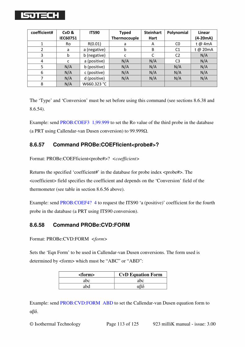
© Isothermal Technology Page 113 of 125 923 milliK manual - issue: 3.00
coefficient# CvD &
IEC60751
ITS90 Typed
Thermocouple
Steinhart
Hart
Polynomial Linear
(4-20mA)
1 Ro R(0.01) a A C0 t @ 4mA
2 a a (negative) b B C1 t @ 20mA
3 b b (negative) c C C2 N/A
4 c a (positive) N/A N/A C3 N/A
5 N/A b (positive) N/A N/A N/A N/A
6 N/A c (positive) N/A N/A N/A N/A
7 N/A d (positive) N/A N/A N/A N/A
8 N/A W660.323 °C
The ‘Type’ and ‘Conversion’ must be set before using this command (see sections 8.6.38 and
8.6.54).
Example: send PROB:COEF3 1,99.999 to set the Ro value of the third probe in the database
(a PRT using Callendar-van Dusen conversion) to 99.999Ω.
8.6.57 Command PROBe:COEFficient<probe#>?
Format: PROBe:COEFficient<probe#>? <coefficient>
Returns the specified ‘coefficient#’ in the database for probe index <probe#>. The
<coefficient> field specifies the coefficient and depends on the ‘Conversion’ field of the
thermometer (see table in section 8.6.56 above).
Example: send PROB:COEF4? 4 to request the ITS90 ‘a (positive)’ coefficient for the fourth
probe in the database (a PRT using ITS90 conversion).
8.6.58 Command PROBe:CVD:FORM
Format: PROBe:CVD:FORM <form>
Sets the ‘Eqn Form’ to be used in Callendar-van Dusen conversions. The form used is
determined by <form> which must be “ABC” or “ABD”:
<form> CvD Equation Form
abc abc
abd αβδ
Example: send PROB:CVD:FORM ABD to set the Callendar-van Dusen equation form to
αβδ.
© Isothermal Technology Page 114 of 125 923 milliK manual - issue: 3.00
8.6.59 Command PROBe:CVD:FORM?
Format: PROBe:CVD:FORM?
Returns the form of the Callendar-van Dusen equation used. The returned value will be either
“abc” or “abd”.
Example: send PROB:CVD:FORM? to request the form of the Callendar-Van Dusen
equation used.
8.6.60 Command PROBe:ITS90:FORM<probe#>
Format: PROBe:ITS90:FORM<probe#> <form>
For the thermometer with probe index <probe>, sets whether the ‘a (negative)’ and ‘b
(negative)’ coefficients (those in the left-hand column of the ITS90 coefficient window) are
used with the ITS90 deviation function equation for below the WTP (water triple-point) or
the deviation function for the mercury to gallium range. The equation used is determine by
the <form> parameter, which must be either “T<WPT” or “HG<T<GA”.
Example: send PROB:ITS90:FORM3 T<WTP to set the ‘a’ and ‘b’ negative coefficients to
be used with the deviation function for temperature below the WTP for the third probe in the
database.
8.6.61 Command PROBe:ITS90:FORM<probe#>?
Format: PROBe:ITS90:FORM<probe#>?
Returns the deviation function used with the ITS90 ‘a’ and ‘b’ negative coefficients for the
thermometer with probe index <probe> in the database. The returned value will be either
“T<WTP” or “Hg<T<Ga”.
Example: send PROB:ITS90:FORM4? to request the ITS90 deviation function form to be
used with the ‘a’ and ‘b’ negative coefficients for the fourth thermometer in the database.
8.6.62 Command PROBe:CREate
Format: PROBe:CREate <name>
© Isothermal Technology Page 115 of 125 923 milliK manual - issue: 3.00
Creates a new entry at the end of the thermometer database with name <name>.
Example: send PROB:CRE my new probe to create a new thermometer in the database called
“my new probe”.
8.6.63 Command PROBe:DELete<probe#>
Format: PROBe:DELete<probe#>
Deletes the probe in the database with index <probe>. N.B. after a probe is deleted from the
database, the database is re-indexed and the order of the probes is indeterminate. The order of
the probes can, of course, be re-determined using PROBe:NAMe<probe>? command (see
section 8.6.37).
Example: send PROB:DEL5 to delete the fifth probe in the database.
8.6.64 Command PROBe:FIND?
Format: PROBe:FIND? <name>
Findss the database index number for a probe with the field ‘Name’ set to <name>.
Example: send PROB:FIND? SPRT-1 to find the index number of the thermometer named
“SPRT-1”.
8.6.65 Command CALibrate:UNLock
Format: CALibrate:UNLock <password>
Unlocks the milliK to allow calibration adjustment. The milliK always powers up in the
locked state. Calibration can be re-locked by cycling the power to the milliK or using
CAL:LOCK (see section 8.6.66).
Example: send CAL:UNL 1234 to unlock (enable) the calibration adjustment on a milliK
with the default password (“1234”).
8.6.66 Command CALibrate:LOCK
Format: CALibrate:LOCK
Locks the milliK to prevent calibration adjustment.
© Isothermal Technology Page 116 of 125 923 milliK manual - issue: 3.00
Example: send CAL:LOCK to lock the calibration of a milliK after adjustment.
8.6.67 Command CALibrate:RESistance:GAIN
Format: CALibrate:RESistance:GAIN <range>,<current>,<gain>,[<standard>]
Sets the resistance measurement <gain> for the specified resistance <range> and <current>
with the option to specify the <standard> used. Gains outside the range 0.99 to 1.01 are
ignored. The optional <standard> parameter is a string that is stored in the calibration
database file (which can be exported to a USB flash drive: see section 5.4) and can be used to
identify the calibration standard used. Typically, it would be used to identify the serial
number of the standard. The <current> can be specified as either NORMal or ROOT2.
Example: for a milliK that has been found to require a resistance gain of 1.001234 for the
resistance range 0-460Ω with normal (1mA) sense current by using a resistance standard with
serial number xyz1956, the gain can be set using:
CAL:RES:GAIN 460,NORM,1.001234,SN_xyz1956
or CAL:RES:GAIN 460,NORM,1.001234
8.6.68 Command CALibrate:RESistance:GAIN?
Format: CALibrate:RESistance:GAIN? <range>,<current>
Reports the resistance measurement gain for the specified resistance <range> and
<current>. The <current> can be specified as either NORMal or ROOT2. The milliK will
accept gains for the thermistor range (500kΩ) with root2 current, but this is not used
(thermistors measurements are always made with a 2µA sense current)
Example: send CAL:RES:GAIN? 115,NORM to read the resistance gain for the 115Ω range
with normal (1mA) sense current.
8.6.69 Command CALibrate:VOLTage:OFFSet<channel#>
Format: CALibrate:VOLTage:OFFSet<channel#> <offset>
Sets the <offset> added to voltage measurements made on <channel>. The default units for
the offset are milli-volts. Offsets outside the range ±10µV are ignored.
Example: to apply (add) an offset of 2µV (0.002mV) to voltage measurements made on
channel 1, use:
© Isothermal Technology Page 117 of 125 923 milliK manual - issue: 3.00
CAL:VOLT:OFFS1 0.002
or CAL:VOLT:OFFS1 2uV
8.6.70 Command CALibrate:VOLTage:OFFset<channel>?
Format: CALibrate:VOLTage:OFFSet<channel#>?
Reports the <offset> added to voltage measurements made on <channel> in volts.
Example: a milliK with a +1µV offset added to voltage measurement made on channel 1 will
respond to CAL:VOLT:OFFS1? with: “0.00000100”
8.6.71 Command CALibrate:VOLTage:GAIN
Format: CALibrate:VOLTage:GAIN <gain>[,<standard>][,<additional info>]
Sets the <gain> used for voltage measurements. Gains outside the range 0.98 to 1.02 are
ignored. The optional <standard> and <additional info> parameters are strings that are
stored in the calibration database file (which can be exported to a USB flash drive: see
section 5.4) to provide information about this calibration. Typically <standard> would be
used to identify the serial number of the voltage standard used. The <additional info>
parameter is provided so store an additional serial number in case two standards are used
(precise low voltages are often realised by using a calibrated reference resistor together with a
current source).
Example: for a milliK that has been found to require a voltage gain of 1.001234 by using a
standard resistor with serial number xyz1956 and a current source with serial number
abc9960, set the gain using:
CAL:VOLT:GAIN 1.001234,SN_xyz1956,SN_abc9960
or CAL:VOLT:GAIN 1.001234
8.6.72 Command CALibrate:VOLTage:GAIN?
Format: CALibrate:VOLTage:GAIN?
Reports the voltage measurement gain.
Example: a milliK with a voltage gain set to 1.001234 will respond to CAL:VOLT:GAIN?
with “1.001234”
© Isothermal Technology Page 118 of 125 923 milliK manual - issue: 3.00
8.6.73 Command CALibrate:CURRent:GAIN
Format: CALibrate:CURRent:GAIN <gain>[,<standard>]
Sets the <gain> used for current measurements. Gains outside the range 0.98 to 1.02 are
ignored. The optional <standard> parameter is a string that is stored in the calibration
database file (which can be exported to a USB flash drive: see section 5.4) to provide
information about this calibration. Typically, it would be used to identify the serial number of
the standard used. Example: for a milliK that has been found to require a current gain of
1.001234 by using a reference standard with serial number xyz1956, set the gain using:
CAL:CURR:GAIN 1.001234,SN_xyz1956
or CAL:VOLT:GAIN 1.001234
8.6.74 Command CALibrate:CURRent:GAIN?
Format: CALibrate:CURRent:GAIN?
Reports the current measurement gain.
Example: a milliK with a current gain set to 1.001234 will respond to CAL:CURR:GAIN?
with “1.001234”
8.6.75 Command CALibrate:RJC:OFFSet
Format: CALibrate:RJC:OFFSet <offset>[,<TC type>][,<serial#>][,<info>]
Sets the <offset> (in °C) added to measurements of thermocouple reference junction
temperatures. Offsets outside the range ±10°C are ignored. The optional parameters are
strings that are stored in the calibration database file (which can be exported to a USB flash
drive: see section 5.4) to provide information about this calibration. Typically, these would be
used to store information on the thermocouple type used in the calibration, the serial number
of this thermocouple and additional information such as the serial number of the temperature
source used.
Example: to apply (add) an offset of 0.05°C to the reference junction measurements
determine by using a type N thermocouple with serial number xyz1956 in a liquid bath with
serial number abc9960 use:
CAL:RJC:OFFS 0.05,type_N,xyz1956,abc9960
© Isothermal Technology Page 119 of 125 923 milliK manual - issue: 3.00
or CAL:RJC:OFFS 0.05
8.6.76 Command CALibrate:RJC:OFFSet?
Format: CALibrate:RJC:OFFSet?
Reports the <offset> (in °C) added to measurements made by the reference junction sensor
used for reference junction compensation.
Example: a milliK with +0.1°C added to reference junction temperature measurements will
respond to CAL:RJC:OFFS? with: “0.1”.
8.6.77 Command CALibrate:IDENtification
Format: CALibrate:IDENtification <name>,<company>,<location>,<temperature>
Sets identification information used to “stamp” any calibrations that are made after this
command (until the milliK is restarted or the command is resent). This information would
typically be used to store information on the calibration technician, the calibration
organisation and environment.
Example: for calibrations made by John Smith at Isotech at Isotech’s primary standards
laboratory operating at 20°C ± 1°C, send CAL:IDEN JSmith,Isotech,Primary_Lab,19-20C
8.6.78 Command CALibrate:IDENtification?
Format: CALibrate:IDENtification?
Reports the calibration information that will be used to “stamp” subsequent calibrations.
Example: a milliK that has been set to stamp calibrations using the information shown in
section 8.6.77 would respond to CAL:IDEN? with: “JSmith,Isotech,Primary_Lab,19-20C”
8.6.79 Command CALibrate:IDENtification:LAST?
Format: CALibrate:IDENtification:LAST?
Reports the calibration information for the last calibration made to the milliK.
Example: for a milliK that had been calibrated by Joe Bloggs of Metrosol in their secondary
laboratory at 20°C ±2°C and had not had any calibration adjustment applied since, the
response to CAL:IDEN? might be “JBloggs,Metrosol,Secondary_Lab,18-22C”

© Isothermal Technology Page 120 of 125 923 milliK manual - issue: 3.00
8.6.80 Command CALibrate:PASSword
Format: CALibrate:PASSword <old password>,<password>,<password>
Changes the password used to lock (protect) the calibration of the milliK’s measurement
system. This is initially set to “1234”, but should be changed before using the milliK for any
critical or traceable measurement or calibration work. The new password must be at least 4
characters in length and must be typed in identically twice in order to effect the change.
Example: send CAL:PASS 1234,ABCD,ABCD to change the password from 1234 to ABCD.
8.6.81 Command CALibrate:VALid?
Format: CALibrate:VALid?
Reports whether the calibration information loaded from the milliK’s database is valid. If it is
not valid, it will provide an error code that should be reported to Isotech when requesting
technical support.
Example: a correctly calibrated milliK will respond to CAL:VAL? with “Calibration Okay”.
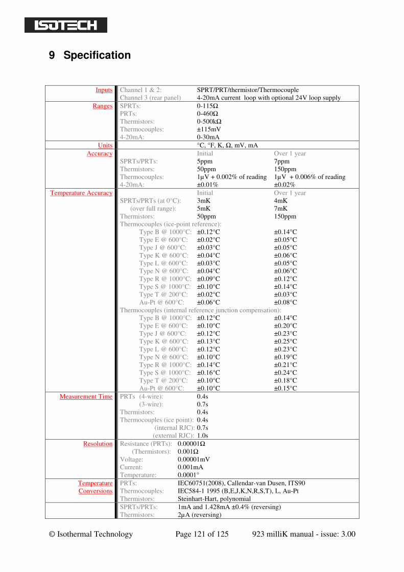
© Isothermal Technology Page 121 of 125 923 milliK manual - issue: 3.00
9 Specification
Inputs Channel 1 & 2: SPRT/PRT/thermistor/Thermocouple
Channel 3 (rear panel) 4-20mA current loop with optional 24V loop supply
Ranges SPRTs: 0-115Ω
PRTs: 0-460Ω
Thermistors: 0-500kΩ
Thermocouples: ±115mV
4-20mA: 0-30mA
Units °C, °F, K, Ω, mV, mA
Accuracy Initial Over 1 year
SPRTs/PRTs: 5ppm 7ppm
Thermistors: 50ppm 150ppm
Thermocouples: 1µV + 0.002% of reading 1µV + 0.006% of reading
4-20mA: ±0.01% ±0.02%
Temperature Accuracy Initial Over 1 year
SPRTs/PRTs (at 0°C): 3mK 4mK
(over full range): 5mK 7mK
Thermistors: 50ppm 150ppm
Thermocouples (ice-point reference):
Type B @ 1000°C: ±0.12°C ±0.14°C
Type E @ 600°C: ±0.02°C ±0.05°C
Type J @ 600°C: ±0.03°C ±0.05°C
Type K @ 600°C: ±0.04°C ±0.06°C
Type L @ 600°C: ±0.03°C ±0.05°C
Type N @ 600°C: ±0.04°C ±0.06°C
Type R @ 1000°C: ±0.09°C ±0.12°C
Type S @ 1000°C: ±0.10°C ±0.14°C
Type T @ 200°C: ±0.02°C ±0.03°C
Au-Pt @ 600°C: ±0.06°C ±0.08°C
Thermocouples (internal reference junction compensation):
Type B @ 1000°C: ±0.12°C ±0.14°C
Type E @ 600°C: ±0.10°C ±0.20°C
Type J @ 600°C: ±0.12°C ±0.23°C
Type K @ 600°C: ±0.13°C ±0.25°C
Type L @ 600°C: ±0.12°C ±0.23°C
Type N @ 600°C: ±0.10°C ±0.19°C
Type R @ 1000°C: ±0.14°C ±0.21°C
Type S @ 1000°C: ±0.16°C ±0.24°C
Type T @ 200°C: ±0.10°C ±0.18°C
Au-Pt @ 600°C: ±0.10°C ±0.15°C
Measurement Time PRTs (4-wire): 0.4s
(3-wire): 0.7s
Thermistors: 0.4s
Thermocouples (ice point): 0.4s
(internal RJC): 0.7s
(external RJC): 1.0s
Resolution Resistance (PRTs): 0.00001Ω
(Thermistors): 0.001Ω
Voltage: 0.00001mV
Current: 0.001mA
Temperature: 0.0001°
Temperature
Conversions
PRTs: IEC60751(2008), Callendar-van Dusen, ITS90
Thermocouples: IEC584-1 1995 (B,E,J,K,N,R,S,T), L, Au-Pt
Thermistors: Steinhart-Hart, polynomial
SPRTs/PRTs: 1mA and 1.428mA ±0.4% (reversing)
Thermistors: 2µA (reversing)
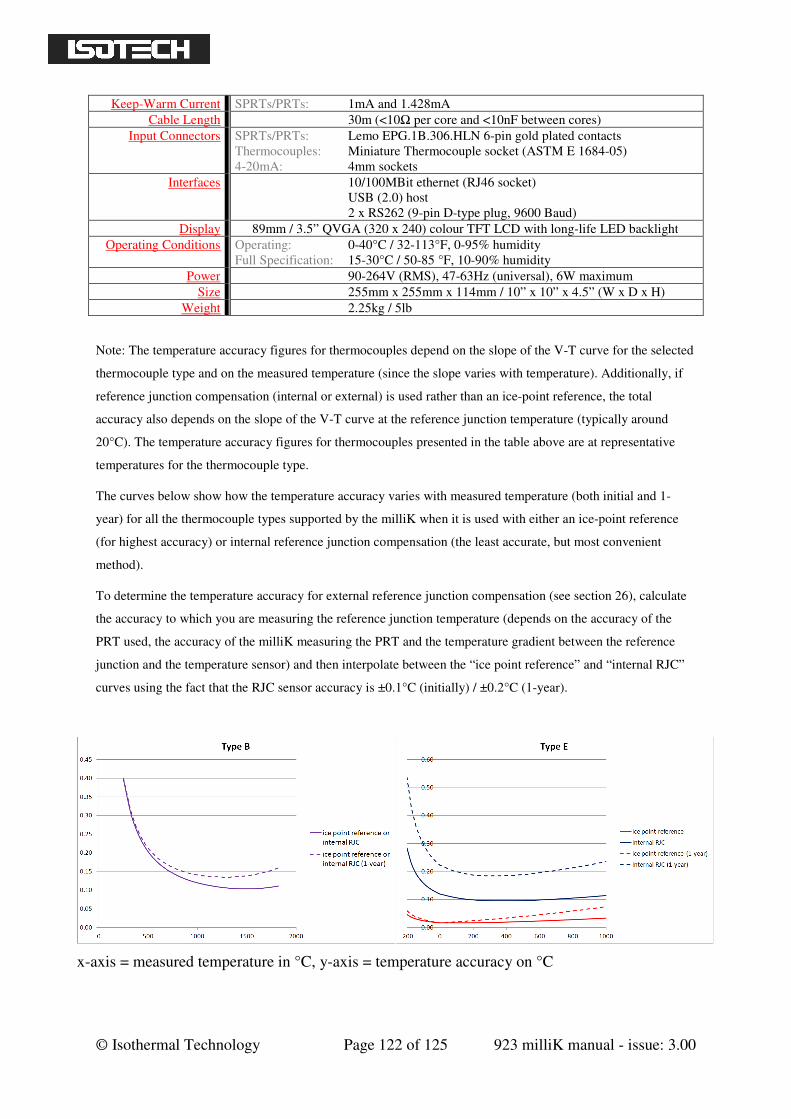
© Isothermal Technology Page 122 of 125 923 milliK manual - issue: 3.00
Keep-Warm Current SPRTs/PRTs: 1mA and 1.428mA
Cable Length 30m (<10Ω per core and <10nF between cores)
Input Connectors SPRTs/PRTs: Lemo EPG.1B.306.HLN 6-pin gold plated contacts
Thermocouples: Miniature Thermocouple socket (ASTM E 1684-05)
4-20mA: 4mm sockets
Interfaces 10/100MBit ethernet (RJ46 socket)
USB (2.0) host
2 x RS262 (9-pin D-type plug, 9600 Baud)
Display 89mm / 3.5” QVGA (320 x 240) colour TFT LCD with long-life LED backlight
Operating Conditions Operating: 0-40°C / 32-113°F, 0-95% humidity
Full Specification: 15-30°C / 50-85 °F, 10-90% humidity
Power 90-264V (RMS), 47-63Hz (universal), 6W maximum
Size 255mm x 255mm x 114mm / 10” x 10” x 4.5” (W x D x H)
Weight 2.25kg / 5lb
Note: The temperature accuracy figures for thermocouples depend on the slope of the V-T curve for the selected
thermocouple type and on the measured temperature (since the slope varies with temperature). Additionally, if
reference junction compensation (internal or external) is used rather than an ice-point reference, the total
accuracy also depends on the slope of the V-T curve at the reference junction temperature (typically around
20°C). The temperature accuracy figures for thermocouples presented in the table above are at representative
temperatures for the thermocouple type.
The curves below show how the temperature accuracy varies with measured temperature (both initial and 1-
year) for all the thermocouple types supported by the milliK when it is used with either an ice-point reference
(for highest accuracy) or internal reference junction compensation (the least accurate, but most convenient
method).
To determine the temperature accuracy for external reference junction compensation (see section 26), calculate
the accuracy to which you are measuring the reference junction temperature (depends on the accuracy of the
PRT used, the accuracy of the milliK measuring the PRT and the temperature gradient between the reference
junction and the temperature sensor) and then interpolate between the “ice point reference” and “internal RJC”
curves using the fact that the RJC sensor accuracy is ±0.1°C (initially) / ±0.2°C (1-year).
x-axis = measured temperature in °C, y-axis = temperature accuracy on °C
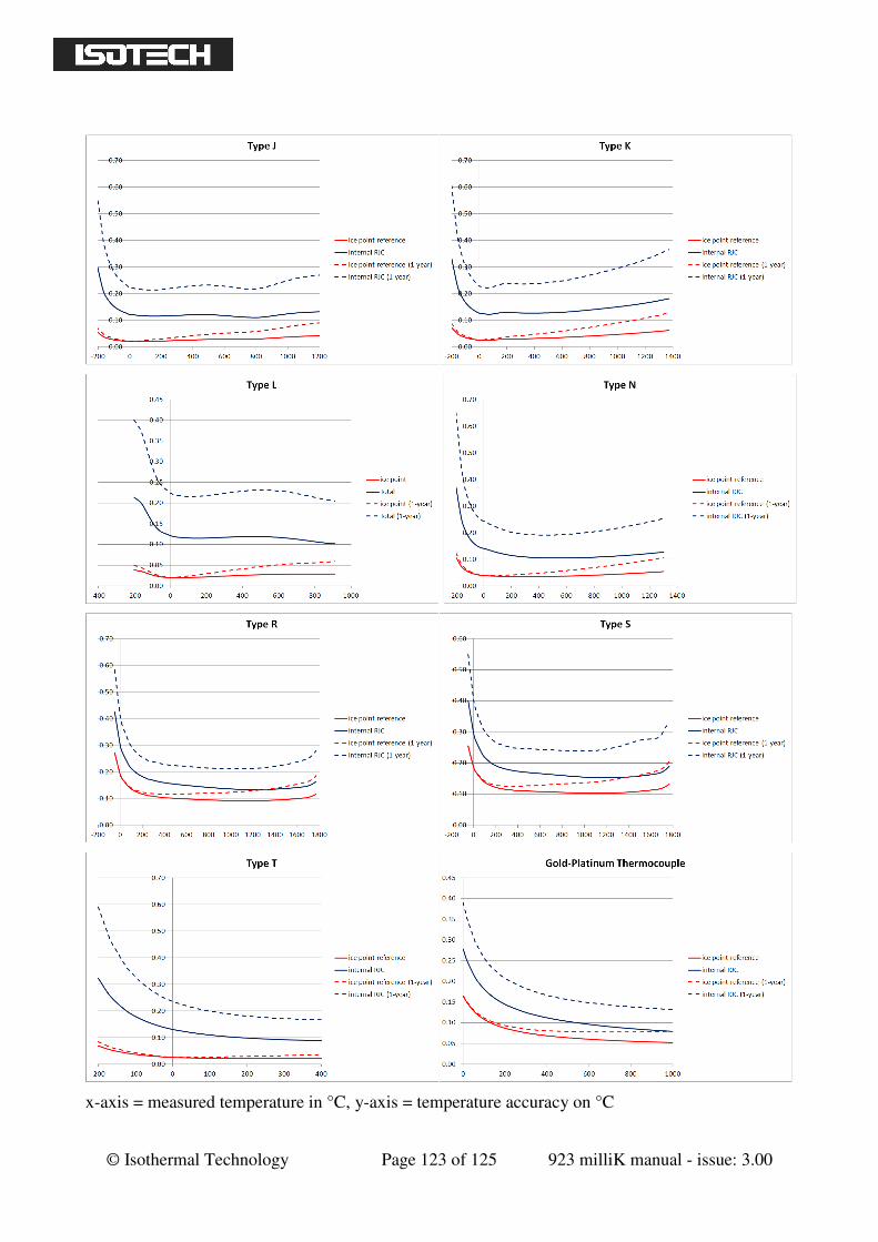
© Isothermal Technology Page 123 of 125 923 milliK manual - issue: 3.00
x-axis = measured temperature in °C, y-axis = temperature accuracy on °C

© Isothermal Technology Page 124 of 125 923 milliK manual - issue: 3.00
10 Approvals
The milliK has been verified as complying with the regulatory requirements of the EU and
FCC for electromagnetic compatibility and safety (EU only).
10.1 CE Declaration
European Community Electromagnetic Compatibility Directive (89/336)
European Community Low Voltage Directive (93/68)
The milliK Precision Thermometer manufactured by Isothermal Technology Limited of Pine
Grove, Southport, Merseyside, PR9 9AG, United Kingdom conforms to the requirements of
the European Community Electromagnetic Compatibility Directive (89/336) and of the
European Community Low Voltage Directive (93/68).
10.2 FCC Statement
This equipment has been tested and found to comply with the limits for a Class A digital
device, pursuant to part 15 of the FCC Rules. These limits are designed to provide reasonable
protection against harmful interference when the equipment is operated in a commercial
environment. This equipment generates and can radiate radio frequency energy and, if not
installed and used in accordance with the instruction manual, may cause harmful interference
to radio communications. Operation of this equipment in a residential area may cause harmful
interference, in which case the user will be required to correct the interference at his own
expense. Changes or modifications to this equipment not expressly approved by Isothermal
Technology could degrade EMC performance and void the user’s authority to operate the
equipment.
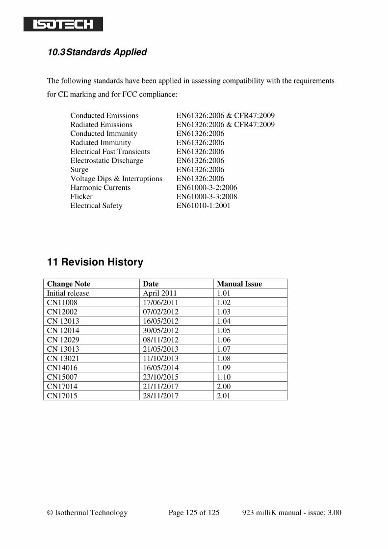
© Isothermal Technology Page 125 of 125 923 milliK manual - issue: 3.00
10.3 Standards Applied
The following standards have been applied in assessing compatibility with the requirements
for CE marking and for FCC compliance:
Conducted Emissions EN61326:2006 & CFR47:2009
Radiated Emissions EN61326:2006 & CFR47:2009
Conducted Immunity EN61326:2006
Radiated Immunity EN61326:2006
Electrical Fast Transients EN61326:2006
Electrostatic Discharge EN61326:2006
Surge EN61326:2006
Voltage Dips & Interruptions EN61326:2006
Harmonic Currents EN61000-3-2:2006
Flicker EN61000-3-3:2008
Electrical Safety EN61010-1:2001
11 Revision History
Change Note Date Manual Issue
Initial release April 2011 1.01
CN11008 17/06/2011 1.02
CN12002 07/02/2012 1.03
CN 12013 16/05/2012 1.04
CN 12014 30/05/2012 1.05
CN 12029 08/11/2012 1.06
CN 13013 21/05/2013 1.07
CN 13021 11/10/2013 1.08
CN14016 16/05/2014 1.09
CN15007 23/10/2015 1.10
CN17014 21/11/2017 2.00
CN17015 28/11/2017 2.01