Embed Size (px)
Citation preview

XinjeXinjeXinjeXinje ElectronicElectronicElectronicElectronic Co.,Co.,Co.,Co., Ltd.Ltd.Ltd.Ltd.
DS2DS2DS2DS2 SeriesSeriesSeriesSeries ServoServoServoServo DriverDriverDriverDriver
UserUserUserUser ManualManualManualManual
Serial No. SC01 20090706
1.0

DS2DS2DS2DS2 SeriesSeriesSeriesSeries ServoServoServoServo DriverDriverDriverDriverUserUserUserUser ManualManualManualManual
SafetySafetySafetySafety PrecautionsPrecautionsPrecautionsPrecautionsContentContentContentContentPrefacePrefacePrefacePreface————————————————————————————————————————————————————————————————CheckingCheckingCheckingChecking ProductProductProductProduct andandandand PartPartPartPart NamesNamesNamesNames————————————————————————————————————————————————————————————————InstallationInstallationInstallationInstallation————————————————————————————————————————————————————————————————WiringWiringWiringWiring————————————————————————————————————————————————————————————————ParameterParameterParameterParameter SettingsSettingsSettingsSettings andandandand FunctionsFunctionsFunctionsFunctions————————————————————————————————————————————————————————————————UseUseUseUse DigitalDigitalDigitalDigital PanelPanelPanelPanel————————————————————————————————————————————————————————————————RatingsRatingsRatingsRatings andandandand CharacteristicsCharacteristicsCharacteristicsCharacteristics————————————————————————————————————————————————————————————————AlarmAlarmAlarmAlarm InformationInformationInformationInformation————————————————————————————————————————————————————————————————

AllAllAllAll copyrightscopyrightscopyrightscopyrights reservedreservedreservedreserved bybybyby XinjeXinjeXinjeXinje ElectronicElectronicElectronicElectronic Co.,Co.,Co.,Co., Ltd.Ltd.Ltd.Ltd.
Any copying, transferring or any other usage is pro hibited. Otherwise Xinje will have the right topursue legal responsibilities. All rights including patent and pemission of modules and designs arereserved.
January,January,January,January, 2010201020102010

a
The following defines the symbols used in this manual to indicate varying degrees ofsafety precautions and to identify the corresponding level of hazard inherent to each.Failure to follow precautions provided in this manual can result in serious, possibly evenfatal, injury, and/or damage to the persons, products, or related equipment and systems.
���� CheckingCheckingCheckingChecking ProductsProductsProductsProducts uponuponuponupon DeliveryDeliveryDeliveryDelivery
���� InstallationInstallationInstallationInstallation
���� WiringWiringWiringWiring
CAUTIONCAUTIONCAUTIONCAUTION Indicates a potentially hazardous situation, which, if not heeded,could result in death or serious injury
WARNINGWARNINGWARNINGWARNING Indicates a potentially hazardous situation, which, if not avoided,may result in minor or moderate injury.
CAUTIONCAUTIONCAUTIONCAUTION
1. DO NOT install any driver which is damaged, lack of accessories or not the same withthe model ordered.
Doing so may result in electric shock.
WARNINGWARNINGWARNINGWARNING
1. Cut off external power supply before installation.Not doing so may result in electric shock.
CAUTIONCAUTIONCAUTIONCAUTION
1. Always use the servomotor and servo amplifier in one of the specified combinations.Never use the products in an environment subject to water, corrosive gases,inflammable gases, or combustibles.Doing so may result in electric shock, fire or malfunction.
2. DO NOT touch any metallic part.Doing so may result in malfunction.
WARNINGWARNINGWARNINGWARNING
1. Cut off external power supply before wiring.Not doing so may result in electric shock.
2.Connect AC power supply to the corresponding terminals.Faulty wiring may result in fire.
Be sure to review this section carefully before use this product. In precondition ofsecurity, wire the product correctly.
SafetySafetySafetySafety PrecautionsPrecautionsPrecautionsPrecautions

b
���� OperationOperationOperationOperation
CAUTIONCAUTIONCAUTIONCAUTION
1. Do not connect a three-phase power supply to the U, V, or W output terminals.Doing so may result in injury or fire.
2. Use 2mm2 wire to grounding the groud terminals.Not doing so may result in electric shock.
3. Securely fasten the power supply terminal screws and motor output terminal screws.Not doing so may result in fire.
WARNINGWARNINGWARNINGWARNING
1. Never touch any rotating motor parts while the motor is running.Doing so may result in injury.
2. DO NOT touch the inside the driver.Doing so may result in electric shock.
3. Do not remove the panel cover while the power is ON.Doing so may result in electric shock.
4. Do not touch terminals for five minutes after the power has been turned OFF.Residual voltage may cause electric shock.
CAUTIONCAUTIONCAUTIONCAUTION
1. Conduct trial operation on the servomotor alone with the motor shaft disconnected frommachine to avoid any unexpected accidents.
Not doing so may result in injury.2. Before starting operation with a machine connected, change the settings to match theparameters of the machine.
Starting operation without matching the proper settings may cause the machine to runout of control or malfunction.3. Before starting operation with a machine connected, make sure that an emergency stopcan be applied at any time.
Not doing so may result in injury.4. Do not touch the heat sinks during operation.
Not doing so may result in burns due to high temperatures.5. Do not attempt to change wiring while the power is ON.
Doing so may result in electric shock or injury

Content
i
ContentContentContentContent
Preface.......................................................................................I
Constitution of This Manual...............................................................I
Intended User.............................................................................I
How to Fetch This Manual...................................................................I
1 Checking Product and Part Names..............................................................1
1-1.Checking Products on Delivery.........................................................1
1-1-1. Servomotors.....................................................................1
1-1-2.Servo Drivers...................................................................2
1-2.Product Part Names....................................................................2
1-2-1.Servomotors.....................................................................2
1-2-2.Servo Drivers...................................................................2
2 Installation.................................................................................5
2-1.Servomotor............................................................................5
2-1-1.Storage Temperature.............................................................5
2-1-2.Installation Site...............................................................5
2-1-3.Alignment.......................................................................5
2-1-4.Orientation.....................................................................6
2-1-5.Handling Oil and Water..........................................................6
2-1-6.Cable Stress....................................................................6
2-2.Servo Drivers.........................................................................6
2-2-1.Storage Conditions..............................................................6
2-2-2.Installation Site...............................................................6
2-2-3.Orientation.....................................................................7
2-2-4.Installation....................................................................7
3 Wiring.......................................................................................9
3-1.Main Circuit Wiring...................................................................9
3-1-1.Names and Descriptions of Main Circuit Terminal.................................9
3-1-2.Typical Wiring Example.........................................................10
3-1-3.Winding Terminals On Servomotor................................................10
3-2.I/O Signals..........................................................................10
3-2-1.Layout Of CN0/CN1 Terminals....................................................10
3-2-2.CN0 and CN1 Signal Names and Functions.........................................11
3-2-3.I/O Signal Names and Functions.................................................11
3-2-4.Interface Circuits.............................................................12
3-3.Wiring Encoders......................................................................13
3-3-1.Encoder Connections............................................................13
3-3-2.CN2 Encoder Connector Terminal Layout..........................................13
3-4.Examples Of Standard Connections.....................................................14
3-4-1.Position Control Mode..........................................................14
3-5.Communication Port...................................................................15
3-5-1.Serial Port 1(COM1)............................................................15
3-5-2.Serial Port 2(COM2)............................................................16
3-6.Regenerative Resistor................................................................16
4 Parameter Settings and Functions............................................................18
4-1.List Of Parameters...................................................................18
4-1-1.Functions P0...................................................................18
4-1-2.Control Parameters P1..........................................................19
4-1-3.Position Control Parameter P2..................................................19
4-1-4.Speed Control Parameter P3.....................................................20
4-1-5.Torque Control Parameter P4....................................................20
4-1-6.Signal Settings P5.............................................................20
4-1-7.Modbus Address.................................................................23
4-2.Settings According to Equipment Characteristics......................................25
4-2-1.Switching Rotation Direction...................................................25
4-2-2.Overtravel Limit(P-OT & N-OT)..................................................25
4-2-3.Servo OFF Stop Mode............................................................27
4-2-4.Torque Limit...................................................................27
4-2-5.Internal Speed Limit In Torque Control.........................................28
4-2-6.Holding Brake (BK).............................................................28

Content
ii
4-3.Settings According to Host Controller................................................31
4-3-1.Speed Reference................................................................31
4-3-2.Position Reference.............................................................31
4-3-3.I/O Signals....................................................................33
4-3-4.Electronic Gear................................................................34
4-3-5.Digital Reference Speed Control................................................36
4-3-6.Torque Control.................................................................38
4-3-7.Encoder Z Signal Output........................................................38
4-4.Setting Up the Servo Driver..........................................................39
4-4-1.Indicating Control Mode........................................................39
4-4-2.Input Signal Assignment........................................................40
4-4-3.Output Signal Assignment.......................................................40
4-4-4.Jog Speed......................................................................41
4-5.Setting Stop Functions...............................................................41
4-5-1.Zero Clamp (/ZCLAMP)...........................................................41
4-6.IO Signals Control...................................................................42
4-6-1.Alarm Output (/ALM)............................................................42
4-6-2.Servo ON Input (S-ON)..........................................................43
4-6-3.Positioning Completed Output (/COIN)...........................................43
4-6-4.Speed Coincidence Output (/V-CMP)..............................................45
4-6-5.Rotation Detection Output (/TGON)..............................................45
4-6-6.Servo Ready Output (/S-RDY)....................................................46
4-6-7.Near Output (/NEAR)............................................................47
4-6-8.Warning Output (WARN)..........................................................48
4-7.Smooth Operation.....................................................................49
4-7-1.Smoothing......................................................................49
4-7-2.Soft Start Function............................................................50
4-8.Gain Adjustments.....................................................................50
4-8-1.Servo Gain Parameters..........................................................50
4-8-2.Using Proportional Control (/P-CON)...........................................51
4-8-3.Gain Selection (/G-SEL)........................................................52
5 Using Digital Panel.........................................................................53
5-1.Basic Operation......................................................................53
5-1-1.Functions Of Digital Panel.....................................................53
5-1-2.Basic Mode Selection...........................................................53
5-2.Status Display Mode..................................................................54
5-3.Monitor Mode.........................................................................56
5-4.Auxiliary Function...................................................................57
5-4-1.Check System Infomation........................................................58
5-4-2.Auxiliary Run Mode.............................................................58
5-4-3. Set Motor Code.................................................................59
5-4-4.Check Alarm Information........................................................59
5-4-5.Reset Parameters To Default....................................................60
5-4-6.External Communication.........................................................60
5-5.Parameter Setting....................................................................60
5-6.Alarm................................................................................61
6 Ratings and Characteristics.................................................................62
6-1.Servomotors..........................................................................62
6-1-1.Servomotor Ratings and Specifications..........................................62
6-1-2.Torque-Speed Feature...........................................................63
6-1-3.Servomotors Dimensions.........................................................63
6-2.Servo Drivers........................................................................67
6-2-1.Ratings........................................................................67
6-2-2.Specifications.................................................................67
6-2-3.Servo Drivers Dimensions.......................................................68
7 Alarm Information...........................................................................71

Content
iii

Preface
I
PrefacePrefacePrefacePreface
CCCConstitutiononstitutiononstitutiononstitution ofofofof TTTThishishishis MMMManualanualanualanual
This manual is divided into 7 chapters.
1. Checking Product and Part Names
This chapter describes the procedure for checking products upon delivery as well as namesfor product parts.
2. Installation
This chapter describes precautions for servomotor and servo driver installation.
3. Wiring
This chapter describes the procedure used to connect DS2 Series products to peripheraldevices and gives typical examples of main circuit wiring as well as I/O signalconnections.
4. Parameter Settings and Functions
This chapter describes the procedure for setting and applying parameters.
5. Use Digital Panel
This chapter describes the basic operation of the digital panel and the features it offers.
6. Ratings and Characteristics
This chapter provides the ratings, torque-speed characteristics diagrams, and dimensionaldrawings of the DS2 series servo drives and MS series servomotors.
7. Alarm Information
This chapter describes the alarm information of DS2 series servo drivers.
IntendedIntendedIntendedIntended UserUserUserUser
This manual is intended for the following users.
� Those designing DS2 Series servodrive systems.
� Those installing or wiring DS2 Series servodrives.
� Those performing trial operation or adjustments of DS2 Series servodrives.
� Those maintaining or inspecting DS2 Series servodrives.
HHHHowowowow totototo AAAAcquirecquirecquirecquireTTTThishishishis MMMManualanualanualanual
1.Electrical Manual(1) Log on Xinje official website www.thinget.com or www.xinje.com to download.(2) Acquire this manual on a CD from an authorized distributor.
This chapter describes the constitution of this manual, the intended user, and how toacquire this manual.
PrefacePrefacePrefacePreface

Preface
II

1 Checking Product and Part Names
1
1111CheckingCheckingCheckingChecking ProductProductProductProduct andandandand PartPartPartPartNamesNamesNamesNamesThis chapter describes the procedure for checking products upon delivery as well as namesfor product parts.
1-11-11-11-1.CheckingCheckingCheckingChecking ProductsProductsProductsProducts onononon DeliveryDeliveryDeliveryDelivery
Use the following checklist when products are delivered.
If any of the above are faulty or incorrect, contact Xinje or an authorized distributor.
1-1-1.1-1-1.1-1-1.1-1-1. ServomotorsServomotorsServomotorsServomotors���� ExternalExternalExternalExternal AppearanceAppearanceAppearanceAppearance
� NameplateNameplateNameplateNameplate
MS -80 ST - M 02430 A Z- 2 0P7CapacityRated Voltage
BrakeShaft SpecificationsPerformance Specifications
Feedback ComponentSinewave Motors
Base SizeMotor Series Name
Base Size: 60, 80, 110, 130;Feedback Component: M(Optical incremental encoder);Performance Specifications: the first 3 decimals indicate the rated torque, and the last 2decimals indicate the rated speed.
01330: Rated Torque1.27N.m, Rated Speed 3000rpm02430: Rated Torque 2.4N·m, Rated Speed 3000rpm;
InitialInitialInitialInitial InspectioInspectioInspectioInspectionnnn CommentsCommentsCommentsCommentsAre the delivered products theones that were ordered?
Check the model numbers marked on the nameplatesof the servomotor and servo driver.
Does the servomotor shaft rotatesmoothly?
The servomotor shaft is normal if it can be turnedsmoothly by hand. Servomotors with brakes,however,cannot be turned manually.
Is there any damage? Check the overall appearance, and check for damageor scratches that may have occurred during shipping.
Are there any loose screws? Check screws for looseness using a screwdriver.
Is the motor code the same withthe code in driver?
Check the motor code marked on the nameplates ofthe servomotor and the parameter F0-00 on the servodriver.

1 Checking Product and Part Names
2
04025: Rated Torque 4.0N·m, Rated Speed 2500rpm;04030: Rated Torque 4.0N·m, Rated Speed 3000rpm;05030: Rated Torque 5.0N·m, Rated Speed 3000rpm;06025: Rated Torque 6.0N·m, Rated Speed 2500rpm;10015: Rated Torque 10.0N·m, Rated Speed 1500rpm;
Shaft Specifications: A - With No Key; B - With A KeyBrake: Null - None; Z - With a DC99V BrakeRated Voltage: 2 - 220V; 4 - 380VCapacity: 0P4-0.4kW; 0P7-0.75kW; 1P5-1.5kW; 2P0 - 2.0kW
1-1-21-1-21-1-21-1-2.ServoServoServoServo DriversDriversDriversDrivers���� ExternalExternalExternalExternal AppearanceAppearanceAppearanceAppearance
���� NameplateNameplateNameplateNameplate
DS2 – 2 0P7
Capacity0P4: 0.4kW; 0P7: 0.75kW; 1P5: 1.5kW
Series Name Rated Voltage2: 220V; 4: 380V
1-21-21-21-2.ProductProductProductProduct PartPartPartPart NamesNamesNamesNames
1-2-11-2-11-2-11-2-1.ServomotorsServomotorsServomotorsServomotors
1-2-21-2-21-2-21-2-2.ServoServoServoServo DriversDriversDriversDrivers���� DS2-20P4DS2-20P4DS2-20P4DS2-20P4,,,, DS2-20P7DS2-20P7DS2-20P7DS2-20P7
DS2-20P4DS2-20P7
DS2-21P5

1 Checking Product and Part Names
3
���� DS2-21P5DS2-21P5DS2-21P5DS2-21P5

1 Checking Product and Part Names
4

2 Installation
5
2222 InstallationInstallationInstallationInstallationThis chapter describes precautions for servomotor and servo driver installation.
2-12-12-12-1.SSSServomotorervomotorervomotorervomotor
MS series servomotors can be installed either horizontally or vertically. The service life ofthe servomotor can be shortened or unexpected problems might occur if it is installedincorrectly or in an inappropriate location. Follow these installation instructions carefully.
2-1-12-1-12-1-12-1-1.StorageStorageStorageStorage TemperatureTemperatureTemperatureTemperatureStore the servomotor within -20~+60℃ as long as it is stored with the power cabledisconnected.
2-1-22-1-22-1-22-1-2.InstallationInstallationInstallationInstallation SiteSiteSiteSiteMS series servomotors are designed for indoor use. Install the servomotor in environmentsthat satisfy the following conditions.
� Free of corrosive or explosive gases.� Well-ventilated and free of dust and moisture.� Ambient temperature of 0° to 50°C.� Relative humidity (r.h.) of 20 to 80% with no condensation.� Accessible for inspection and cleaning.
2-1-32-1-32-1-32-1-3.AlignmentAlignmentAlignmentAlignmentAlign the shaft of the servomotor with the shaft of the equipment, and then couple theshafts. Install the servomotor so that alignment accuracy falls within the following range.
CAUTIONCAUTIONCAUTIONCAUTION
1.The end of the motor shaft is coated with anti-corrosive paint. Before installing,carefully remove all of the paint using a cloth moistened with paint thinner.
2.Avoid getting thinner on other parts of the servomotor.

2 Installation
6
Note:Note:Note:Note: (1) Vibration, which will damage the bearings, will occur if the shafts are notproperly aligned.
(2) When installing the coupling, prevent direct impact to the shaft. This candamage the encoder mounted on the opposite end.
2-1-42-1-42-1-42-1-4.OrientationOrientationOrientationOrientationMS series servomotors can be installed either horizontally or vertically.
2-1-52-1-52-1-52-1-5.HandlingHandlingHandlingHandling OilOilOilOil andandandandWaterWaterWaterWaterInstall a protective cover over the servomotor if it is used in a location that is subject towater or oil mist. Also use a servomotor with an oil seal when needed to seal the through-shaft section.
2-1-62-1-62-1-62-1-6.CableCableCableCable StressStressStressStressMake sure that the power lines are free from bends and tension. Be especially careful towire signal line cables so that they are not subject to stress because the core wires are verythin, measuring only 0.2 to 0.3mm2.
2-22-22-22-2.ServoServoServoServo DriversDriversDriversDriversThe DS2 series servo drivers are base-mounted servo drivers. Incorrect installation willcause problems. Follow the installation instructions below
2-2-12-2-12-2-12-2-1.StorageStorageStorageStorage ConditionsConditionsConditionsConditions
Store the servo driver within -20~+85℃, as long as it is stored with the power cabledisconnected.
2-2-22-2-22-2-22-2-2.InstallationInstallationInstallationInstallation SiteSiteSiteSiteThe following precautions apply to the installation site.
SituatioSituatioSituatioSituationnnn IIIInstallationnstallationnstallationnstallation PrecautionPrecautionPrecautionPrecautionInstallation in aControl Panel
Design the control panel size, unit layout, and cooling method sothe temperature around the servo drivers does not exceed 50°C.

2 Installation
7
2-2-32-2-32-2-32-2-3.OrientationOrientationOrientationOrientationInstall the servo driver perpendicular to the wall as shown in the figure. The servo drivermust be oriented this way because it is designed to be cooled by natural convection or by acooling fan.
2-2-42-2-42-2-42-2-4.InstallationInstallationInstallationInstallationFollow the procedure below to install multiple servo drivers side by side in a control panel.
Installation Near aHeating Unit
Minimize heat radiated from the heating unit as well as anytemperature rise caused by natural convection so the temperaturearound the servo drivers does not exceed 50°C.
Installation Near aSource of Vibration
Install a vibration isolator beneath the servo driver to avoidsubjecting it to vibration.
Installation at a SiteExposed to CorrosiveGas
Corrosive gas does not have an immediate effect on the servodrivers, but will eventually cause electronic components andterminals to malfunction. Take appropriate action to avoidcorrosive gas.
Other Situations Do not install the servo driver in hot and humid locations orlocations subject to excessive dust or iron powder in the air.
2 Installation
8
���� ServoServoServoServo DriverDriverDriverDriver OrientationOrientationOrientationOrientation
Install the servo driver perpendicular to the wall so the front panel containing connectorsfaces outward.
���� CoolingCoolingCoolingCooling
As shown in the figure above, allow sufficient space around each servo driver for coolingby cooling fans or natural convection.
���� Side-by-sideSide-by-sideSide-by-sideSide-by-side InstallationInstallationInstallationInstallation
When installing servo drivers side by side as shown in the figure above, allow at least10mm between and at least 50mm above and below each servo driver. Install cooling fansabove the servo drivers to avoid excessive temperature rise and to maintain eventemperature inside the control panel.
���� EnvironmentalEnvironmentalEnvironmentalEnvironmental ConditionsConditionsConditionsConditions inininin thethethethe ControlControlControlControl PanelPanelPanelPanel
� Ambient Temperature: 0~50℃� Humidity: 90%RH or less� Vibration: 4.9m/s2� Condensation and Freezing: None� Ambient Temperature for Long-term Reliability: 45°C maximum

3 Wiring
9
3333WiringWiringWiringWiringThis chapter describes the procedure used to connect DS2 Series products to peripheraldevices and gives typical examples of main circuit wiring as well as I/O signalconnections.
3-13-13-13-1.MainMainMainMain CircuitCircuitCircuitCircuit WiringWiringWiringWiring
This section shows typical examples of main circuit wiring for DS2 Series servo products,functions of main circuit terminals, and the power ON sequence.Observe the following precautions when wiring.
3-1-13-1-13-1-13-1-1.NamesNamesNamesNames andandandand DescriptionsDescriptionsDescriptionsDescriptions ofofofof MainMainMainMain CircuitCircuitCircuitCircuit TerminalTerminalTerminalTerminalThe following table gives the names and a description of main circuit terminals on DS2-20P4、DS2-20P7 from the top down.
The following table gives the names and a description of main circuit terminals on DS2-21P5 from the top down.
Caution
1. Do not bundle or run power and signal lines together in the same duct. Keep powerand signal lines separated by at least 11.81in(30cm)
2. Use twisted pair wires or multi-core shielded-pair wires for signal and encoder(PG)feedback lines.The maximum length is 118.11in(3m) for reference input lines and is 787.40in(20m)for encoder(PG) feedback lines.
3. Do not touch the power terminals for 5 minutes after turning power OFF because highvoltage may still remain in the servo amplifier.Please make sure to check the wiring after the CHARGE light is going off.
4. Avoid frequently turning power ON and OFF. Do not turn power ON or OFF morethan once per minute.Since the servo amplifier has a capacitor in the power supply, a high charging currentflows for 0.2s when power is turned ON. Frequently turning power ON and OFFcauses main power devices like capacitors and fuses to deteriorate, resulting inunexpected problems.
Symbol Name DescryptionP+、PB External regenerative
resistor terminalConnect an external regenerative resistor between P+and PB.
U、V、W Servomotorconnection terminal
Connects to the Servomotor.
Ground terminal Connects to the motor ground terminal.L、N Main circuit AC input
terminalSingle-phase 200~240V, 50/60Hz
Ground terminal Connects to the power supply ground terminal.
Symbol Name Descryption1、 2 DC reactor terminal
connection for powersupply harmonicwave countermeasure
Normally short 1 and 2.If a countermeasure against power supply harmonicwaves is needed, connect a DC reactor between 1and 2.

3 Wiring
10
3-1-23-1-23-1-23-1-2.TypicalTypicalTypicalTypical WiringWiringWiringWiring ExampleExampleExampleExample
FIL
NL CN2
M
PG
UVW
P+PB
Connect an external regenerative resistor
Servo Drive
1MCCB
1MCCB:circuit - breaker
FIL:filter for disturbance signal
3-1-33-1-33-1-33-1-3.WindingWindingWindingWinding TerminalsTerminalsTerminalsTerminals OnOnOnOn ServomotorServomotorServomotorServomotor
3-23-23-23-2.I/OI/OI/OI/O SignalsSignalsSignalsSignals
This section describes I/O signals for the DS2 series servo driver.
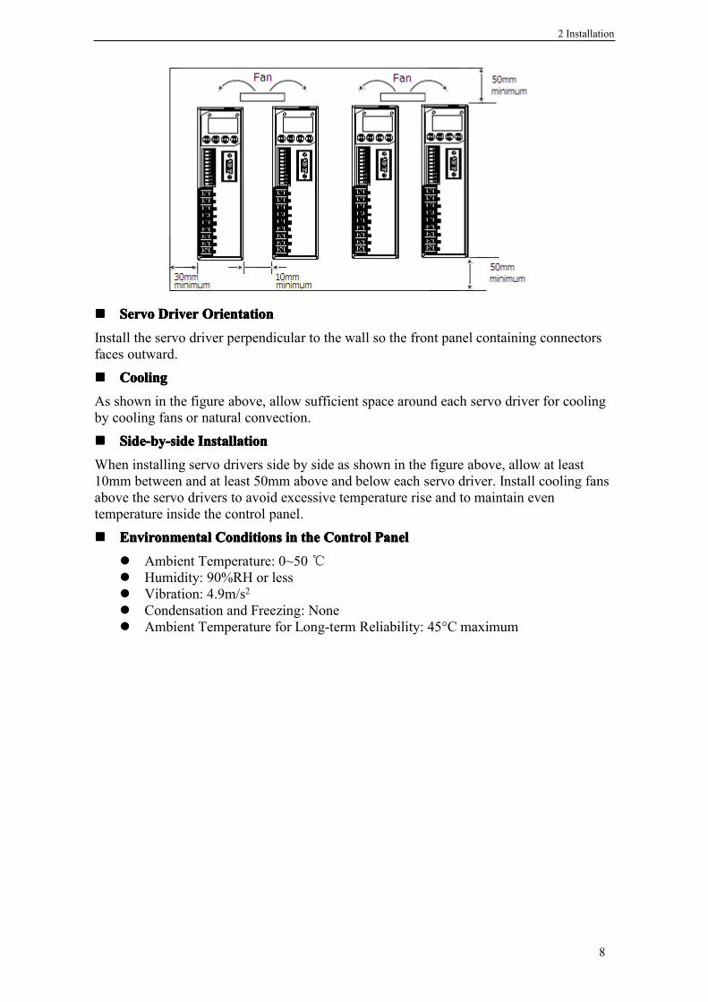
3-2-13-2-13-2-13-2-1.LayoutLayoutLayoutLayout OfOfOfOf CN0/CN1CN0/CN1CN0/CN1CN0/CN1 TerminalsTerminalsTerminalsTerminals
L、N Main circuit AC inputterminal
Single-phase 200~240V, 50/60Hz
Ground terminal Connects to the motor ground terminal.U、V、W Servomotor
connection terminalConnects to the Servomotor.
Ground terminal Connects to the power supply ground terminal.P+、PB External regenerative
resistor terminalConnect an external regenerative resistor between P+and PB.
Symbol 60、80 Series 130 SeriesPE 4 1U 1 2V 3 3W 2 4
DS2-20P4 and DS2-20P7series DS2-21P5 series
Layout of CN1 terminals Layout of CN0 terminals Layout of CN1 terminals
3 Wiring
11
3-2-23-2-23-2-23-2-2.CN0CN0CN0CN0 andandandand CN1CN1CN1CN1 SignalSignalSignalSignal NamesNamesNamesNames andandandand FunctionsFunctionsFunctionsFunctions���� CN0CN0CN0CN0 SignalSignalSignalSignal NamesNamesNamesNames andandandand FunctionsFunctionsFunctionsFunctions
���� CN1CN1CN1CN1 SignalSignalSignalSignal NamesNamesNamesNames andandandand FunctionsFunctionsFunctionsFunctions(1) DS2-20P4 and DS2-20P7
(2) DS2-21P5
3-2-33-2-33-2-33-2-3.I/OI/OI/OI/O SignalSignalSignalSignal NamesNamesNamesNames andandandand FunctionsFunctionsFunctionsFunctionsThe following section describes servo driver I/O signal names and functions.
���� InputInputInputInput SignalsSignalsSignalsSignals
No Symbol Descryption No Symbol Descryption
1 SO1 Output Singal Terminal 1 4 COM Output SingalGround
2 SO2 Output Singal Terminal 2 5 A RS485 +3 SO3 Output Singal Terminal 3 6 B RS485 -
No Symbol Descryption No Symbol Descryption
1 A RS485 + 6 SI2 Input SingalTerminal 2
2 B RS485 - 7 +24V +24V Used ByInput Signals
3 PULS Quadrature Pulse A, Or PulseSignal 8 SO1 Output Singal
Terminal 1
4 SIGN Quadrature Pulse B, Or SignSignal 9 SO2 Output Singal
Terminal 2
5 SI1 Input Singal Terminal 1 10 COM Output SingalGround
No Symbol Descryption No Symbol Descryption
1 PULS Quadrature Pulse A, Or PulseSignal 5 SI2 Input Singal
Terminal 2
2 SIGN Quadrature Pulse B, Or SignSignal 6 SI3 Input Singal
Terminal 3
3 V+ +24V For PULS and SIGN 7 SI4 Input SingalTerminal 4
4 SI1 Input Singal Terminal 1 8 +24V +24V For InputSignals
Class Name Functions ReferenceDigital Input SI1~SI4 Multi-functions Input Terminals 4-1-6、4-4-2
Pulse Input PULS P2-00=1: Quadrature Pulse AP2-00=2: Pulse Signal 4-3-2

3 Wiring
12
���� OutputOutputOutputOutput SignalsSignalsSignalsSignals
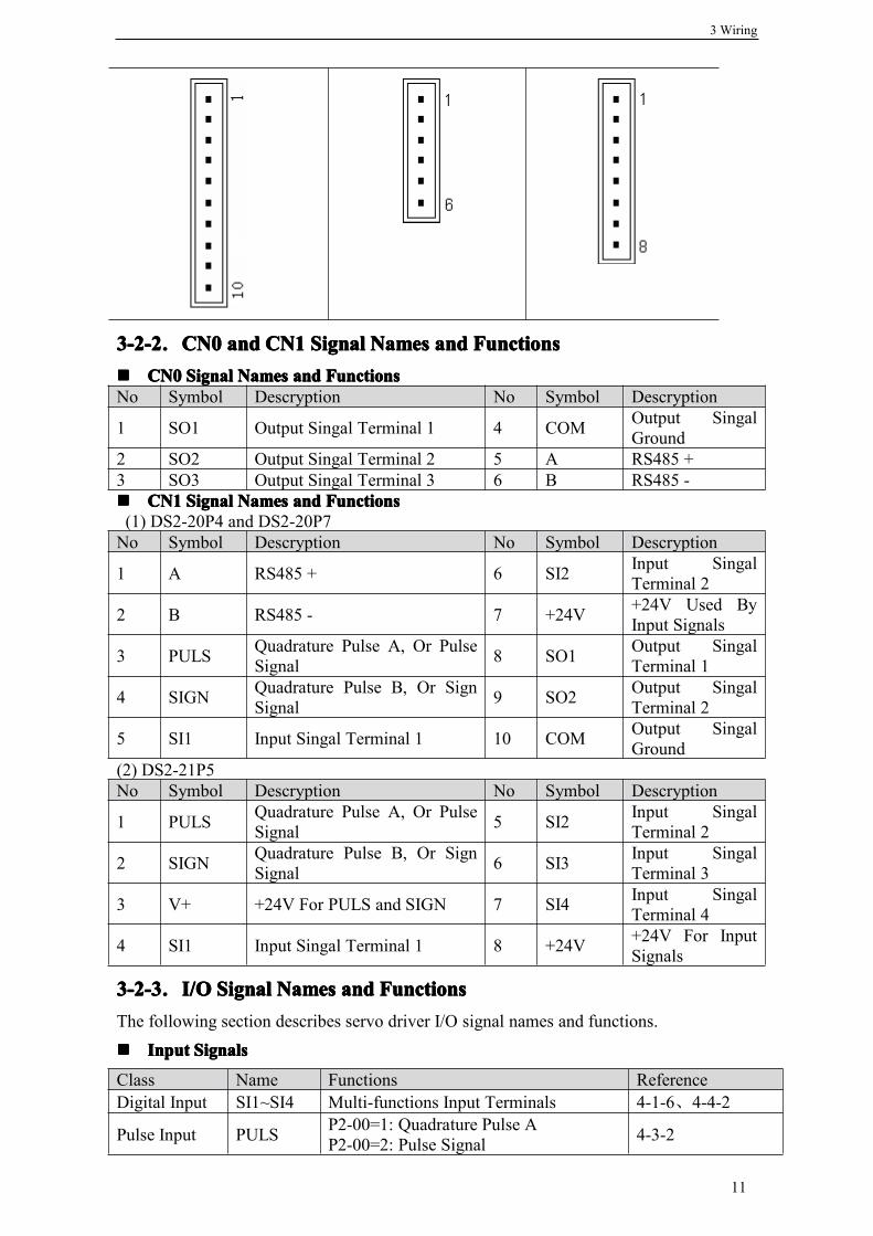
3-2-43-2-43-2-43-2-4.InterfaceInterfaceInterfaceInterface CircuitsCircuitsCircuitsCircuitsThis section shows examples of servo driver I/O signal connection to the host controller.
���� InterfaceInterfaceInterfaceInterface forforforfor ReferenceReferenceReferenceReference InputInputInputInput CircuitsCircuitsCircuitsCircuits
ReferenceReferenceReferenceReference PositionPositionPositionPosition InputInputInputInput CircuitCircuitCircuitCircuit
An output circuit for the reference position signal at the host controller can only beopen-collector type.
� open-collector type(External power supply)
���� InputInputInputInput SignalsSignalsSignalsSignals CircuitCircuitCircuitCircuit InterfaceInterfaceInterfaceInterface
The input signals circuit interface connects through a relay or open-collector transistorcircuit. Select a low-current relay, otherwise a faulty contact will result.
���� OutputOutputOutputOutput SignalsSignalsSignalsSignals CircuitCircuitCircuitCircuit InterfaceInterfaceInterfaceInterface
Output signal terminals of servo driver can only be connected to an open-collector outputcircuit. Please refer to the host controller to connect output signals.
ConnectConnectConnectConnect totototo aaaa photocouplerphotocouplerphotocouplerphotocoupler ConnectConnectConnectConnect totototo aaaa relayrelayrelayrelay
SIGN P2-00=1: Quadrature Pulse BP2-00=2: Sign Signal 4-3-2
Class Name Functions ReferenceDigital Output SO1~SO3 Multi-functions Output Terminals 3-2-4、4-1-6、4-4-3

3 Wiring
13
Note: The maximum allowable voltage and current capacities for open-collector circuitsare:
Voltage: DC30VCurrent: 50mA
3-33-33-33-3.WiringWiringWiringWiring EncodersEncodersEncodersEncoders
The following sections describe the procedure for wiring a servo driver to the encoder.
3-3-13-3-13-3-13-3-1.EncoderEncoderEncoderEncoder ConnectionsConnectionsConnectionsConnectionsThe following diagrams show the wiring of the encoder output from the motor to CN2 ofthe servo driver. This applies to only incremental encoders.
3-3-23-3-23-3-23-3-2.CN2CN2CN2CN2 EncoderEncoderEncoderEncoder ConnectorConnectorConnectorConnector TerminalTerminalTerminalTerminal LayoutLayoutLayoutLayout���� CN2CN2CN2CN2 ConnectorConnectorConnectorConnector TerminalTerminalTerminalTerminal LayoutLayoutLayoutLayout
The following diagrams show the layout of CN2 connector(facing the soler pin).

3 Wiring
14
���� CN2CN2CN2CN2 ConnectorConnectorConnectorConnector TerminalTerminalTerminalTerminal DescriptionDescriptionDescriptionDescription
3-43-43-43-4.ExamplesExamplesExamplesExamples OfOfOfOf StandardStandardStandardStandard ConnectionsConnectionsConnectionsConnections
The following diagrams show examples of standard servo driver connections byspecifications and type of control.The I/O signals used on input and output terminals are assigned by default. Thisassignment could be changed in various conditions. Please refer to 4-1-6.
3-4-13-4-13-4-13-4-1.PositionPositionPositionPosition ControlControlControlControlModeModeModeMode� DS2-20P4 and DS2-20P7
alarm output
DS2-20P7
7
6
5
4
3
3.3KΩ/SIGN
/PULS
/ALM-RST
+24VIN
/S-ON
PE
FIL
10
9
8COIN
ALM
COM
N
LCN2
PEWVU
M
PG
UVW
A
B
1
2
P+
PB
CN1
single-phase AC 220V(50/60Hz)
regnerative resistor
for signal :connect shield to ground ;for drive:leave shield in space
positioning completed
user define
be sure to properly prepare the end of the shielded wire
� DS2-21P5
DriverSide
Encoder Side On MotorName Driver
Side
Encoder Side On MotorName60 and 80
series110 and 130
series60 and 80series
110 and 130series
1 9 4 A+ 2 4 5 B+3 7 6 Z+ 4 6 10 U+5 11 12 W+ 6 13 7 A-7 14 8 B- 8 5 9 Z-9 8 13 U- 10 15 15 W-11 1 1 Shield 12 3 3 GND13 2 2 5V 14 10 11 V+15 12 14 V-

3 Wiring
15
WVU
PG
M
UVW
single-phase AC 220V(50/60Hz)
be sure to properly prepare the end of the shielded wire
PE
CN2
1
2
L
N
P+
PB
S-RDY
COM
ALM
COIN1
2
3
4
user define
FIL
PE
/S-ON
+24VIN
/ALM-RST
/P-OT
/N-OT
/PULS
/SIGN positioning completed
alarm output
ready
3.3KΩ
1
2
4
5
6
7
8
5
6
DS2-21P5
Vcc +24VIN
3.3KΩ
3
regnerative resistor
for signal :connect shield to ground ;for drive:leave shield in space
CN0
CN1
B
A
3-53-53-53-5.CommunicationCommunicationCommunicationCommunication PortPortPortPort
3-5-13-5-13-5-13-5-1.SerialSerialSerialSerial PortPortPortPort 1(1(1(1(COM1COM1COM1COM1))))COM1 supports RS232, and is often used to connected with PC for debugging. Beforedoing this, “F5-00” on the panel should be switched to “C-OUT”, and the panel will beinvalidated. On leaving this status, use the panel to exit, and PC disconnect from servodriver. Please refer to 5-4-6.Communication parameters of COM1 is fixed:Baudrate: 19200bps; Data bits: 8 bits; Stop bits: 1 bit; Parity: even parity; Modbus stationnumber: 1.� DS2-20P4 and DS2-20P7 has a trapeziform terminal with 5 pins.
1 5
NNNNote:ote:ote:ote: Please plug COM1 with special connector from Xinje.
� DS2-21P5 has a DB8 terminal.
Number Name Description1 TXD RS232 TXD2 RXD RS232 RXD3 GND RS232 GND

3 Wiring
16
3-5-23-5-23-5-23-5-2.SerialSerialSerialSerial PortPortPortPort 2(COM2)2(COM2)2(COM2)2(COM2)COM2 supports RS485 and is placed to “A” and “B” terminals on CN0(DS2-21P5) orCN1(DS2-20P4 and DS2-20P7). It bases on Modbus-RTU protocol. Please refer to 3-2-1.
Communication parameters of COM2 can be set by P0-04.
Modbus station number can be set freely, depending on the following parameter.
NNNNote:ote:ote:ote: Parameters above will take effect after power on.
3-63-63-63-6.RegenerativeRegenerativeRegenerativeRegenerative ResistorResistorResistorResistor
When the servomotor operates in generator mode, power is returned to the servo driverside. This is called regenerative power. The regenerative power is absorbed by chargingthe smoothing capacitor, but when the capacitor’s charging limit is exceeded, theregenerative power needs to be reduced by the regenerative resistor.The servomotor is driven in regeneration (generator) mode in the following conditions:
� While decelerating to a stop during acceleration/deceleration operation.� With a load on the vertical axis.� During continuous operation with the servomotor driven from the load side (negative
load).
Connecting Regenerative Resistors
ParameterNumber
Name Default Setting Range
P0-04.0 Baudrate 6 0: 3001: 6002: 12003: 24004: 48005: 96006: 192007: 384008: 576009: 115200
P0-04.1 Data Bits 0 0: 8bitsP0-04.2 Stop Bits 2 0: 2bits. 2: 1bitP0-04.3 Parity 2 0: No Parity. 1: Odd Parity. 2: Even Parity
ParameterNumber Name Unit Default Setting Range
P0-03 Modbus Station Number - 1 1~255
Number Name Description2 UPGRADE Self Upgrade4 RXD RS232 RXD5 TXD RS232 TXD8 GND RS232 GND

3 Wiring
17
Note:Note:Note:Note: Adequate cooling must be provided for regenerative resistors because they reachvery high temperatures. Also use heat-resistant, non-flammable wire and make sure thatthe wiring does not come into contact with the resistors.
Note:Note:Note:Note: The Recommended Power means that the value may be suitable to most applications.Nervertheless, in some special conditions, actual power could be more or less than therecommended value, so the rated power should be flexible to actual temperature of theregenerative resistor.
Motor Model RecommendedResistance
RecommendedPower
MinimumResistance
MS-60ST-M01330□□-20P4 50Ω 100W 40ΩMS-80ST-M02430□□-20P7 50Ω 100W 40ΩMS-110ST-M06030□□-21P5 50Ω 100W 40ΩMS-130ST-M10015□□-21P5 50Ω 300W 40Ω
Connect an external regenerativeresistor between P+ and PB.

4 Parameter Settings and Functions
18
4444ParameterParameterParameterParameter SettingsSettingsSettingsSettings andandandand FunctionsFunctionsFunctionsFunctionsThis chapter describes the procedure for setting and applying parameters.
4-14-14-14-1.ListListListList OfOfOfOf ParametersParametersParametersParameters
Time of taking effect: “○” Re-enable servo driver“●” Restart servo driver“√” Be effective at any time
A hex parameter has a prefix “n.” denoting this parameter is a hex value.Composing of a parameter: PX-XX= n.×× ××
PX-XX. H PX-XX.L
4444----1-11-11-11-1.FunctionsFunctionsFunctionsFunctions P0P0P0P0
Modbus Address: 0x0000~0x00FFP0-
Name Unit DefaultSetting
SettingRange
Time ofTakingEffect
Reference
00 Main Mode - 0 0 ○ 4-4-101 Sub Mode 1
0: Idle1: Torque (Digital Reference)2: Torque (Analog Reference)3: Speed (Digital Reference)4: Speed (Analog Reference)5: Position (Digital Reference)6: Position (Pulse Reference)7: Speed (Pulse Reference)
- 0 0~7 ○ 4-4-1
02 Sub Mode 20~7 Same as above
- 0 0~7 ○ 4-4-1
03 Modbus station number ofCOM2
- 1 1~255 ● 3-5-2
04 Communication parameters ofCOM2
- n.2206 n.0000~n.2209
● 3-5-2
05 Rotation Direction - 0 0, 1 ● 4-2-106 06.L: Servo OFF Stop Mode
DS2 series servo driver is fixedwith “Coasts the servomotor toa stop”.
- 2 0~2 ● 4-2-2
06.H: Overtravel Stop Mode0~1: Coasts the servomotor to astop.2: Decelerates the servomotor toa stop at the preset torque, andthen locks the servomotor inZero Clamp Mode. Torquesetting: P4-06 Emergency StopTorque.3: Decelerates the servomotor to
- 2 0~3 ● 4-2-3

4 Parameter Settings and Functions
19
4-1-24-1-24-1-24-1-2.ControlControlControlControl ParametersParametersParametersParameters P1P1P1P1
Modbus Address: 0x0100~0x01FF
4-1-34-1-34-1-34-1-3.PositionPositionPositionPosition ControlControlControlControl ParameterParameterParameterParameter P2P2P2P2
Modbus Address: 0x0200~0x02FF
a stop at the preset torque, andputs the servomotor in coaststatus. Torque setting: P4-06Emergency Stop Torque.
07 T-REF AssignmentNot available to DS2 seriesservo driver.
- 0 0~3 ○
08 V-REF AssignmentNot available to DS2 seriesservo driver.
- 0 0, 1 ○
P1- Name Unit DefaultSetting
SettingRange
Time ofTakingEffect
Reference
00 Speed Loop Gain 1Hz 100 1~5000 √ 4-8-101 Speed Loop Integral Time
Contant0.1ms 400 1~5000 √ 4-8-1
02 Position Loop Gain 1/s 30 1~2000 √ 4-8-103 Reserved04 2nd Speed Loop Gain 1Hz 150 1~5000 √ 4-8-305 2nd Speed Loop Integral
Time Contant0.1ms 100 1~5000 √ 4-8-3
06 2nd Position Loop Gain 1/s 80 1~2000 √ 4-8-307 Reserved08 Reserved09 Position Loop Feed Forward 1% 0 0~100 √ 4-3-210 Position Loop Feed Forward
Filter Time Contant0.01ms 0 0~65535 √
P2- Name Unit DefaultSetting
SettingRange
Time ofTakingEffect
Reference
00 Input Pulse Form - 2 1, 2 ● 4-3-201 Position Reference Filter
Type- 0 0, 1 ● 4-7-1
02 Electronic Gear Ratio(Numerator)
- 1 1~65535 ○ 4-3-4
03 Electronic Gear Ratio(Denominator)
- 1 1~65535 ○ 4-3-4
04 Position Reference FilterTime Contant
ms 0 0~100 ● 4-7-1
05 Reserved06 Pulse Frequency On Rated
Speed100Hz 5000 1~10000 ○ 4-3-1
07 Pulse Filter Time Contant OfSpeed Control
0.1ms 20 0~1000 √ 4-3-1

4 Parameter Settings and Functions
20
4-1-44-1-44-1-44-1-4.SpeedSpeedSpeedSpeed ControlControlControlControl ParameterParameterParameterParameter P3P3P3P3
Modbus Address: 0x0300~0x03FF
4-1-54-1-54-1-54-1-5.TorqueTorqueTorqueTorque ControlControlControlControl ParameterParameterParameterParameter P4P4P4P4
Modbus Address: 0x0400~0x04FF
4-1-64-1-64-1-64-1-6.SignalSignalSignalSignal SettingsSettingsSettingsSettings P5P5P5P5
Modbus Address: 0x0500~0x05FF
P3- Name Unit DefaultSetting
Setting Range Time ofTakingEffect
Reference
00 Input Voltage OnRated Speed
0.01V 1000 150~3000 ○ 4-3-1
01 Speed 1 rpm 100 -5000~+5000 √ 4-3-502 Speed 2 rpm 200 -5000~+5000 √ 4-3-503 Speed 3 rpm 300 -5000~+5000 √ 4-3-504 JOG Speed rpm 100 0~1000 √ 4-4-405 Acceleration Time ms 0 0~65535 ○ 4-3-506 Deceleration Time ms 0 0~65535 ○ 4-3-507 Speed Reference
Filter TimeConstant
0.01ms 0 0~65535 ○
08 Speed FeedbackFilter TimeConstant
0.01ms 20 0~65535 ○
09 Maximum SpeedLimit
rpm Rated Speed3000: 4000Rated Speed1500: 2000
0~5000 ○
P4- Name Unit DefaultSetting
SettingRange
TimeofTakingEffect
Reference
00 Input Voltage On RatedTorque
0.01V 1000 150~3000 ○ 4-3-6
01 Torque Reference FilterTime Constant
0.01ms 0 0~65535 ○
02 Forward Torque Limit 1% 300 0~300 √ 4-2-403 Reverse Torque Limit 1% 300 0~300 √ 4-2-404 Forward External Torque
Limit1% 100 0~300 √ 4-2-4
05 Reverse External TorqueLimit
1% 100 0~300 √ 4-2-4
06 Emergency Stop Torque 1% 300 0~300 ○ 4-2-207 Speed Limit during Torque
Controlrpm 2000 0~5000 ○ 4-2-5
08 Reserved09 Torque Digital Reference 1% 0 -300~300 √ 4-3-6
P5- Name Unit DefaultSetting
SettingRange
Timeof Taki
Reference

4 Parameter Settings and Functions
21
ngEffect
00 Positioning Completed Width/COIN
refunit
7 0~250 ○ 4-6-3
01 Zero Clamp Speed Level/ZCLAMP
rpm 10 0~300 ○ 4-5-2
02 Rotation Detection Speed Level/TGON
rpm 20 1~1000 ○ 4-6-5
03 Speed Coincidence Signal OutputWidth/V-CMP
rpm 10 1~250 ○ 4-6-4
04 Positioning Nearing Signal Width/NEAR
refunit
50 0~10000 ○ 4-6-7
05 Position Error Overflow Level 256refunit
1000 0~65535 ○ 4-8-1
06 Delay Time from Brake Output toServo OFF
1ms 0 0~500 ○ 4-2-6
07 Brake Output Speed Limit rpm 100 0~5000 ○ 4-2-608 Brake Output Time Limit 1ms 500 10~1000 ○ 4-2-609 Input Terminal Filter Time 5ms 0 0~100 √10 /S-ON
Servo Onn.0000: Signal is fixed to “OFF”.n.0001: Input from SI1.n.0002: Input from SI2.n.0003: Input from SI3.n.0004: Input from SI4.n.0010: Signal is fixed to “ON”n.0011: Input from SI1, reversed.n.0012: Input from SI2, reversed.n.0013: Input from SI3, reversed.n.0014: Input from SI4, reversed.
- n.0001 n.0000~n.0012※1
● 4-6-2
11 /P-CONProportional ControlSame As Above
- n.0000 n.0000~n.0012※1
● 4-8-2
12 /P-OTForward ProhibitedSame As Above
- n.0000※3
n.0000~n.0012※1
● 4-2-2
13 /N-OTReverse ProhibitedSame As Above
- n.0000※4
n.0000~n.0012※1
● 4-2-2
14 /ALM-RSTAlarm ResetSame As Above
- n.0000 n.0000~n.0012※1
● 4-6-1
15 /P-CLForward External Torque LimitSame As Above
- n.0000 n.0000~n.0012※1
● 4-2-4
16 /N-CLReverse External Torque LimitSame As Above
- n.0000 n.0000~n.0012※1
● 4-2-4
17 /SPD-D - n.0000 n.0000~ ● 4-3-5

4 Parameter Settings and Functions
22
Digital Reference Speed SelectionSame As Above
n.0012※1
18 /SPD-ADigital Reference Speed SelectionSame As Above
- n.0000 n.0000~n.0012※1
● 4-3-5
19 /SPD-BDigital Reference Speed SelectionSame As Above
- n.0000 n.0000~n.0012※1
● 4-3-5
20 /C-SELControl Mode SelectionSame As Above
- n.0000 n.0000~n.0012※1
● 4-4-1
21 /ZCLAMPZero ClampSame As Above
- n.0000 n.0000~n.0012※1
● 4-5-2
22 /INHIBITPulse InhibitSame As Above
n.0000 n.0000~n.0012※1
●
23 /G-SELGain SelectionSame As Above
- n.0000 n.0000~n.0012※1
● 4-8-3
24 /CLRPulse Error ClearSame As Above
- n.0000 n.0000~n.0012※1
● 4-3-2
25 Reserved26 Reserved27 Reserved28 /COIN
Positioning Completedn.0000: Do not output.n.0001: Output to SO1.n.0002: Output to SO2.n.0003: Output to SO3.n.0011: Output to SO1, reversed.n.0012: Output to SO2, reversed.n.0013: Output to SO3, reversed.
- n.0001 n.0000~n.0012※2
● 4-6-3
29 /V-CMPSpeed CoincidenceSame As Above
- n.0000 n.0000~n.0012※2
● 4-6-4
30 /TGONRotation DetectionSame As Above
- n.0000 n.0000~n.0012※2
● 4-6-5
31 /S-RDYServo ReadySame As Above
- n.0000※5
n.0000~n.0012※2
● 4-6-6
32 /CLTTorque Limit ReachedSame As Above
- n.0000 n.0000~n.0012※2
● 4-2-4
33 /VLTSpeed Limit ReachedSame As Above
- n.0000 n.0000~n.0012※2
● 4-2-5
34 /BK - n.0000 n.0000~ ● 4-2-6

4 Parameter Settings and Functions
23
※1: Setting range of DS2-21P5 is “n.0000~n.0014”.※2: Setting range of DS2-21P5 is “n.0000~n.0013”.※3: Default setting of DS2-21P5 is “n.0013”.※4: Default setting of DS2-21P5 is “n.0014”.※5: Default setting of DS2-21P5 is “n.0003”.
4-1-74-1-74-1-74-1-7.ModbusModbusModbusModbus AddressAddressAddressAddress
All of the Modbus address are presented in hex.
���� ParameterParameterParameterParameter AddressAddressAddressAddress
BrakeSame As Above
n.0012※2
35 /WARNWarnSame As Above
- n.0000 n.0000~n.0012※2
● 4-6-8
36 /NEARPositioning NearingSame As Above
- n.0000 n.0000~n.0012※2
● 4-6-7
37 /ALMAlarmSame As Above
- n.0002 n.0000~n.0012※2
● 4-6-1
38 /ZEncoder Z SignalSame As Above
n.0000 n.0000~n.0012※2
● 4-3-7
ParameterNumber
ModbusAddress
ParameterNumber
ModbusAddress
ParameterNumber
ModbusAddress
ParameterNumber
ModbusAddress
P0-00 0x0000 P1-00 0x0100 P2-00 0x0200 P3-00 0x0300P0-01 0x0001 P1-01 0x0101 P2-01 0x0201 P3-01 0x0301P0-02 0x0002 P1-02 0x0102 P2-02 0x0202 P3-02 0x0302P0-03 0x0003 P1-03 0x0103 P2-03 0x0203 P3-03 0x0303P0-04 0x0004 P1-04 0x0104 P2-04 0x0204 P3-04 0x0304P0-05 0x0005 P1-05 0x0105 P2-05 0x0205 P3-05 0x0305P0-06 0x0006 P1-06 0x0106 P2-06 0x0206 P3-06 0x0306P0-07 0x0007 P1-07 0x0107 P2-07 0x0207 P3-07 0x0307P0-08 0x0008 P1-08 0x0108 P3-08 0x0308
P1-09 0x0109 P3-09 0x0309P1-10 0x010A
ParameterNumber
ModbusAddress
ParameterNumber
ModbusAddress
ParameterNumber
ModbusAddress
ParameterNumber
ModbusAddress
P4-00 0x0400 P5-00 0x0500 P5-13 0x050D P5-26 0x051AP4-01 0x0401 P5-01 0x0501 P5-14 0x050E P5-27 0x051BP4-02 0x0402 P5-02 0x0502 P5-15 0x050F P5-28 0x051CP4-03 0x0403 P5-03 0x0503 P5-16 0x0510 P5-29 0x051DP4-04 0x0404 P5-04 0x0504 P5-17 0x0511 P5-30 0x051EP4-05 0x0405 P5-05 0x0505 P5-18 0x0512 P5-31 0x051FP4-06 0x0406 P5-06 0x0506 P5-19 0x0513 P5-32 0x0520P4-07 0x0407 P5-07 0x0507 P5-20 0x0514 P5-33 0x0521P4-08 0x0408 P5-08 0x0508 P5-21 0x0515 P5-34 0x0522P4-09 0x0409 P5-09 0x0509 P5-22 0x0516 P5-35 0x0523

4 Parameter Settings and Functions
24
���� MonitorMonitorMonitorMonitor AddressAddressAddressAddress
���� InputInputInputInput SignalsSignalsSignalsSignals
���� OutputOutputOutputOutput SignalsSignalsSignalsSignals
P5-10 0x050A P5-23 0x0517 P5-36 0x0524P5-11 0x050B P5-24 0x0518 P5-37 0x0525P5-12 0x050C P5-25 0x0519 P5-38 0x0526
Description ModbusAddress Description Modbus
AddressCurrent Speed 0x0700 Current Alarm Code 0x0716Speed Reference 0x0701 Current Warn Code 0x0717Torque Reference 0x0702 Alarm/Warn Code Histroy 1 0x0718Angle(Mechenical Angle) 0x0703 U Current when Alarm raised 0x0719Angle(Electrical Angle) 0x0704 V Current when Alarm raised 0x071ADC Voltage 0x0705 DC Voltage when Alarm raised 0x071BTemperature 0x0706 Temperature when Alarm raised 0x071CInput Pulse Speed 0x0707 Speed when Alarm raised 0x071DPulse Error(Low Word) 0x0708 Torque when Alarm raised 0x071EPulse Error(High Word) 0x0709 V-REF when Alarm raised 0x071FPosition In One Circle (LowWord) 0x070A T-REF when Alarm raised 0x0720
Position In One Circle (HighWord) 0x070B Alarm/Warn Code Histroy 2 0x0728
Pulse Input(Low Word) 0x070C Alarm/Warn Code Histroy 3 0x0729Pulse Input(High Word) 0x070D Alarm/Warn Code Histroy 4 0x072APulse Feedback(Low Word) 0x070E Alarm/Warn Code Histroy 5 0x072BPulse Feedback(High Word) 0x070F Alarm/Warn Code Histroy 6 0x072CTotal Position(Low Word) 0x0710 Alarm/Warn Code Histroy 7 0x072DTotal Position(High Word) 0x0711Current Current 0x0712V-REF Voltage 0x0713T-REF Voltage 0x0714
Description Modbus Address Description Modbus Address/S-ON 0x0800 /SPD-A 0x0808/P-CON 0x0801 /SPD-B 0x0809/P-OT 0x0802 /C-SE 0x080A/N-OT 0x0803 /ZCLAMP 0x080B/ALM-RST 0x0804 Undefined 0x080C/P-CL 0x0805 /G-SEL 0x080D/N-CL 0x0806 /CLR 0x080E/SPD-D 0x0807
Description Modbus Address Description Modbus Address/COIN 0x0812 /BK 0x0818/V-CMP 0x0813 /WARN 0x0819/TGON 0x0814 /NEAR 0x081A/S-RDY 0x0815 /ALM 0x081B/CLT 0x0816 /Z 0x081C/VLT 0x0817

4 Parameter Settings and Functions
25
4-24-24-24-2.SettingsSettingsSettingsSettings AccordingAccordingAccordingAccording totototo EEEEquipmentquipmentquipmentquipment CharacteristicsCharacteristicsCharacteristicsCharacteristics
This section describes the procedure for setting parameters according to the dimensionsand performance characteristics of the equipment used.
4-2-14-2-14-2-14-2-1.SwitchingSwitchingSwitchingSwitching RotationRotationRotationRotation DirectionDirectionDirectionDirectionThe servo amplifier has a Reverse Rotation Mode that reverses the direction of servomotorrotation without rewiring. Forward rotation in the standard setting is defined ascounterclockwise as viewed from the load.
With the Reverse Rotation Mode, the direction of servomotor rotation can be reversedwithout changing other parameters. Only the direction of shaft motion is reversed.
���� SettingSettingSettingSetting ReverseReverseReverseReverse RotationRotationRotationRotation ModeModeModeMode
Use the parameter P0-05 to reverse the rotation direction.
Note:Note:Note:Note: This parameter could not take effect until restart servo driver.
4-2-24-2-24-2-24-2-2.OvertravelOvertravelOvertravelOvertravel LimitLimitLimitLimit((((P-OTP-OTP-OTP-OT&&&&N-OTN-OTN-OTN-OT))))The overtravel limit function forces movable equipment parts to stop if they exceed theallowable range of motion.
���� UsingUsingUsingUsing thethethethe OvertravelOvertravelOvertravelOvertravel FunctionFunctionFunctionFunction
To use the overtravel function, connect the overtravel limit switch input signal terminalsshown below to the servo driver CN1 connector.
Connect limit switches as shown below to prevent damage to the devices during linearmotion.
Standard Setting Reverse Rotation Mode
ForwardReference
ReverseReference
Parameter Name Unit SettingRange
DefaultSetting
P0-05 Rotation Direction - 0, 1 0
P0-05 Description
0 Forward rotation is defined as counterclockwise (CCW)rotation as viewed from the load. (Standard Setting)
1 Forward rotation is defined as clockwise(CW) rotation asviewed from the load.
(Reverse RotationMode)
Input Signal Name Control Mode/POT Forward Prohibited Speed, Torque and Position Control/NOT Reverse Prohibited Speed, Torque and Position Control

4 Parameter Settings and Functions
26
���� Enabling/DisablingEnabling/DisablingEnabling/DisablingEnabling/Disabling OvertravelOvertravelOvertravelOvertravel FunctionFunctionFunctionFunction
Set the following parameters to specify whether input signals are used for overtravel or not.DS2-20P4 and DS2-20P7 is set to “not used”; DS2-21P5 is set to “used”.
※1: Setting range of DS2-21P5 is “n.0000~n.0014”.※2: Default setting of DS2-21P5 is “n.0013”.※3: Default setting of DS2-21P5 is “n.0014”.
NNNNote:ote:ote:ote: There would be superfluous pulse after stopped by overtravel function. Use clearsignal(/CLR) to clear the pulse error.
���� StopStopStopStopModeModeModeMode forforforfor OvertravelOvertravelOvertravelOvertravel
Set the following parameters to specify the Overtravel Stop Mode when P-OT and N-OTinput signals are used.
Parameter Description Unit SettingRange
DefaultSetting
P5-12
Always prohibit: P5-12 is set to n.0010, meansalways pohibit forward running. It is rarely used.Always not prohibit: P5-12 is set to n.0000,which means always allow running forward.Input from terminal: The last number of P5-12 isthe terminal that input P-OT signal. The nextnumber indicates if the signal is reversed, and “1”indicates the signal is reversed.
-n.0000~n.0012
※1
n.0000※2
P5-13
Always prohibit: P5-13 is set to n.0010, meansalways pohibit forward running. It is rarely used.Always not prohibit: P5-13 is set to n.0000,which means always allow running forward.Input from terminal: The last number of P5-13 isthe terminal that input P-OT signal. The nextnumber indicates if the signal is reversed, and “1”indicates the signal is reversed.
-n.0000~n.0012
※1
n.0000※3
Parameter Name Unit SettingRange
DefaultSetting
P0-06.H Overtravel Stop Mode - 0~3 2
Setting Of P0-06.H Description
0 Coasts the servomotor to a stop.1 Coasts the servomotor to a stop.
2 Decelerates the servomotor to a stop at the preset torque, and then locksthe servomotor in Zero Clamp Mode.

4 Parameter Settings and Functions
27
NNNNote:ote:ote:ote:
(1) When the overtravel signal becomes effective, servomotor is forced OFF if OvertravelStop Mode is set to “0” and “1”, or motor is not forced OFF before it is stopped ifOvertravel Stop Mode is set to “2”, or motor is not forced OFF until /S-ON is OFF ifOvertravel Stop Mode is set to “3”.
(2) Servomotor stopping is qualified by rotation detection speed(Unit: rpm).
4-2-34-2-34-2-34-2-3.ServoServoServoServo OFFOFFOFFOFF StopStopStopStopModeModeModeModeDS2 series servo driver turn motor off under following condition:� The Servo ON input signal (/S-ON) is OFF.� A alarm is raised.� Power is turned OFF.
Whatever P0-06.L is set, DS2 series servo driver always coasts the servomotor to a stop
4-2-44-2-44-2-44-2-4.TorqueTorqueTorqueTorque LimitLimitLimitLimitTorque limit function is enabled when servo driver is in either Position Mode or SpeedMode.If current torque exceeds the limit, /CLT signal is set to “ON”.Use the parameter P5-32 to select which terminal will output the /CLT signal.
Servo driver has 2 functions to limit torque as followed:� Internal Torque Limit� External Torque Limit
���� InternalInternalInternalInternal TorqueTorqueTorqueTorque LimitLimitLimitLimit(Maximum(Maximum(Maximum(Maximum TorqueTorqueTorqueTorque ForForForFor Output)Output)Output)Output)
Internal Torque Limit function is used to limit the maximun torque by parameter whenrunning in common.
These settings are effective as long as servo being on (enabled). The unit is a percentage tothe rated torque of a motor.
If torque limit is set higher than the maximum torque of the servomotor, the maximumtorque of the servomotor is the limit.
Torque setting: P4-06 Emergency Stop Torque.
3Decelerates the servomotor to a stop at the preset torque, and puts theservomotor in coast status.Torque setting: P4-06 Emergency Stop Torque.
Parameter Description Unit SettingRange
DefaultSetting
P0-06.L Servo OFF Stop Mode - 0~2 2
Signal Signal Status Reverse Or Not Terminal Status Description
/CLT(P5-32)
ONDirect Output On between SO and COM Exceed
limitReverse Output Off between SO and COM
OFFDirect Output On between SO and COM
NormalReverse Output Off between SO and COM
Parameter Name Unit SettingRange
DefaultSetting Control Mode
P4-02 Forward Torque Limit 1% 0~300 300 Position Control,Speed Control
P4-03 Reverse Torque Limit 1% 0~300 300 Position Control,Speed Control

4 Parameter Settings and Functions
28
The default setting is 300, which means 300% of rated torque.
NNNNote:ote:ote:ote: (1) If P4-02 or P4-03 is set much smaller, insufficient torque will be output whenaccelerating or decelerating.
(2) Maximum torque limit percentage may be different from various motors.
���� ExternalExternalExternalExternal TorqueTorqueTorqueTorque LimitLimitLimitLimit(Limit(Limit(Limit(Limit TorqueTorqueTorqueTorque ByByByBy Signal)Signal)Signal)Signal)
External torque limit function is used to limit the torque when motor moves into specifiedstate, i.e, forcing stop and robot holding pieces.Setting a torque percentage and then inputting a signal will take this function into effect.
NNNNote:ote:ote:ote: The unit is a percentage to the rated torque of a motor.
4-2-54-2-54-2-54-2-5.InternalInternalInternalInternal SpeedSpeedSpeedSpeed LimitLimitLimitLimit InInInIn TorqueTorqueTorqueTorque ControlControlControlControlInternal speed limit function is enabled in only torque control mode.If current speed exceeds the limit, the /VLT signal is set to “ON”.
/VLT signal assignment can be modified by indicating the given parameter.
Default setting is n.0000, and /VLT doesn’t assigned to any output terminal. Please referto 4-3-3 to see how to set the signal assignment.
※1: Default setting of DS2-21P5 is “n.0013”.
���� InternalInternalInternalInternal SpeedSpeedSpeedSpeed LimitLimitLimitLimit LevelLevelLevelLevel
4-2-64-2-64-2-64-2-6.HoldingHoldingHoldingHolding BrakeBrakeBrakeBrake ((((BKBKBKBK))))The holding brake is used when a servo driver controls a vertical axis. In other words, aservomotor with brake prevents the movable part from shifting due to the force of gravitywhen system power goes OFF.
Parameter Name Unit SettingRange
DefaultSetting Control Mode
P4-04 Forward ExternalTorque Limit 1% 0~300 100 Position Control, Speed
Control
P4-05 Reverse ExternalTorque Limit 1% 0~300 100 Position Control, Speed
Control
Signal Output Status Reverse Or Not Terminal Status Description
/VLTON
Direct Output On between SO and COM ExceedlimitReverse Output Off between SO and COM
OFFDirect Output On between SO and COM
NormalReverse Output Off between SO and COM
Parameter Name Unit Setting Range DefaultSetting
P5-33 Speed Limit ReachedAssignment - n.0000~n.0012※1 n.0000
Parameter Name Unit SettingRange
DefaultSetting
ControlMode
P4-07 Speed Limit duringTorque Control rpm 0~5000 2000 Torque
Control

4 Parameter Settings and Functions
29
���� WiringWiringWiringWiring ExampleExampleExampleExample
Use the servo output signal /BK and the brake power supply to form a brake ON/OFFcircuit. The following diagram shows a standard wiring example.
Note:Note:Note:Note: For 110 and 130 series motors, voltage between L1 and L2 is AC220V, besides, for60 and 80 series motors it is AC48V.
In the diagram above, the /BK signal is assigned to SO1, and the parameter P5-34 must beset to n.0011.
This output signal controls the brake when using a servomotor with a brake and does nothave to be connected when using a servomotor without a brake.
���� BrakeBrakeBrakeBrake OutputOutputOutputOutput TimingTimingTimingTiming (After(After(After(After MotorMotorMotorMotor IsIsIsIs Stopped)Stopped)Stopped)Stopped)
If the equipment moves slightly due to gravity when the brake is applied, set the followingparameter to adjust brake ON timing.
Signal Status Control Mode/BK Brake Output Position Control, Speed Control and Torque Control
Signal Output Status Reverse Or Not Terminal Status Description
/BKON
Direct Output On between SO and COM Brake On(Brake)Reverse Output Off between SO and COM
OFFDirect Output On between SO and COM Brake OFF
(Release)Reverse Output Off between SO and COM
Parameter Name Unit SettingRange
DefaultSetting Control Mode
P5-06 Delay Time from 1ms 0~500 0 Position Control, Speed Con
The brake built into the MS series servomotorwith brakes is a de-energization brake, which isused only to hold and cannot be used forbraking. Use the holding brake only to hold astopped motor. Brake torque is about 120% ofthe rated motor torque.

4 Parameter Settings and Functions
30
This parameter is used to set the output time from the brake control signal /BK until theservo OFF operation (servomotor output stop).
With the standard setting, the servo is turned OFF when the /BK signal (brake operation)is active. The equipment may move slightly due to gravity depending on equipmentconfiguration and brake characteristics. If this happens, use this parameter to delay servoOFF timing.This setting sets the brake ON timing when the servomotor is stopped.
���� BrakeBrakeBrakeBrake OutputOutputOutputOutput TimingTimingTimingTiming (When(When(When(When MotorMotorMotorMotor IsIsIsIs Rotating)Rotating)Rotating)Rotating)
Set the following parameters to adjust brake ON timing so the holding brake is appliedwhen the servo driver stops a rotating motor.
Set the brake timing used when input signal /S-ON is turned OFF or when an alarm occursduring motor operation.
Brake ON timing when the servomotor stops must be adjusted properly becauseservomotor brakes are designed for holding position not for decelerating. Adjust theparameter settings while observing equipment operation.
The /BK signal is ON under either of the following conditions:1. Motor speed drops below the setting at P5-07 after servo OFF.2. The time set at P5-08 has elapsed since servo OFF.
The actual speed used will be the maximum speed even if P5-07 is set higher than the
Brake Output toServo OFF trol and Torque Control
Parameter Name Unit SettingRange
DefaultSetting Control Mode
P5-07 Brake OutputSpeed Limit
rpm 0~5000 100 Position Control, SpeedControl and Torque Control
P5-08 Brake Output TimeLimit
1ms 10~1000 500 Position Control, SpeedControl and Torque Control

4 Parameter Settings and Functions
31
maximum speed.
4-34-34-34-3.SettingsSettingsSettingsSettings AccordingAccordingAccordingAccording totototo HostHostHostHost ControllerControllerControllerController
4-3-14-3-14-3-14-3-1.SpeedSpeedSpeedSpeed ReferenceReferenceReferenceReferenceInput the speed reference using the input signal Speed Reference Input. Since this signalhas various uses, set the optimum reference input for the system created.
���� FrequencyFrequencyFrequencyFrequency OfOfOfOf InputInputInputInput PulsePulsePulsePulse ReferenceReferenceReferenceReference
Speed reference is in direct proportion to the frequency of input pulse string, and thereference is independent of the total number of the pulse string.The circuit is the same as the circuit of position reference. The reference pulse form can beselected from “Quadrature Pulse Signal” and “Sign & Pulse Signal”.Set the following parameter to indicate input pulse form.
Set reference pulse form input to the servo driver from the host controller.
Set the following parameter to adjust the gain of frequency of input pulse.
Set the following parameter to adjust the filter time contant of frequency of input pulse.
4-3-24-3-24-3-24-3-2.PositionPositionPositionPosition ReferenceReferenceReferenceReferenceThe “Quadrature Pulse Signal” and “Sign & Pulse Signal” are used for the positionreference. Since this signal can be used in different ways, set the optimum reference inputfor the system created.
���� ReferenceReferenceReferenceReference PulsePulsePulsePulse InputInputInputInput CircuitCircuitCircuitCircuitPositioning is controlled by inputting a reference pulse for a move.
Parameter Name Unit SettingRange
DefaultSetting
Control Mode
P2-00 Input Pulse Form - 1, 2 2 Position Control,Speed Control
Parameter Setting Input Pulse FormP2-00 1 Quadrature Pulse Signal (multiplied 4)
2 Sign & Pulse Signal
Parameter Name Unit SettingRange
DefaultSetting
ControlMode
P2-06 Pulse Frequency On Rated Speed 100Hz 1~10000 5000 SpeedControl
Parameter Name Unit SettingRange
DefaultSetting
ControlMode
P2-07 Pulse Filter Time ContantOf Speed Control
0.1ms 0~1000 20 SpeedControl

4 Parameter Settings and Functions
32
Note:Note:Note:Note: The following table shows the signal logic for an open-collector output.
���� SelectingSelectingSelectingSelecting aaaa ReferenceReferenceReferenceReference PulsePulsePulsePulse FormFormFormForm
Set the following parameter to indicate input pulse form.
Set reference pulse form input to the servo driver from the host controller.
Diagram of “Quadrature Pulse Signal (multiplied 4)”
Reference Pulse Input Signal Timing
���� PulsePulsePulsePulse ErrorErrorErrorError ClearClearClearClear InputInputInputInput /CLR/CLR/CLR/CLR
Tr1, Tr2 = ON Equivalent to low-level inputTr1, Tr2 = OFF Equivalent to high-level input
Parameter Name Unit SettingRange
DefaultSetting
Control Mode
P2-00 Input Pulse Form - 1, 2 2 Position Control,Speed Control
Parameter Setting Input Pulse FormP2-00 1 Quadrature Pulse Signal (multiplied 4)
2 Sign & Pulse Signal
Reference Pulse Form Electrical Specifications Remarks
Sign+Pulse Input(SIGN+PULS Signal)Maximum referencefrequency:Differential: 500kbpsOpen-collector: 200kbps°
t1, t2 ≤ 0.1μst3, t7 ≤ 0.1μst4, t5, t6 > 3μsτ≥ 2.5μs(τ/T) × 100 = 40%~60%
SIGNHigh=ForwardreferenceLow=Reverse reference
Quadrature Pulse SignalMaximum referencefrequency:Differential: 500kbpsOpen-collector: 200kbps
t1, t2 ≤ 0.1μsτ≥ 2.5μs(τ/T) × 100 = 40%~60%
A leads B ahead at 90°:Forward referenceB leads A ahead at 90°:Reverse reference

4 Parameter Settings and Functions
33
The error clear signal /CLR clears the error counter of servo driver, and the positionreference is set to current position.
���� ControlControlControlControl DiagramDiagramDiagramDiagram
4-3-34-3-34-3-34-3-3.I/OI/OI/OI/O SignalsSignalsSignalsSignalsI/O signals are used to control servo driver operation. Connect these signal terminals asrequired.
���� InputInputInputInput SignalSignalSignalSignal ConnectionsConnectionsConnectionsConnections
Connect the input signals as shown below.
Note:Note:Note:Note:(1) Provide a separate external I/O power supply; the servo driver does not have aninternal 24V power supply.External power supply specifications: 24V ±1 VDC, 300mA minimum(2) Recommend that using the same type of external power supply as that used for outputcircuits.
���� OutOutOutOutputputputput SignalSignalSignalSignal ConnectionsConnectionsConnectionsConnections
Connect the output signals as shown in the following figure.
Signal Input Description Control Mode+24V +24V External power supply Position Control, Speed Control and
Torque Control
4 Parameter Settings and Functions
34
Note:Note:Note:Note:(1) Provide a separate external I/O power supply; the servo driver does not have aninternal 24V power supply.External power supply specifications: 24V ±1 VDC, 300mA minimum
(2) Recommend that using the same type of external power supply as that used for outputcircuits.
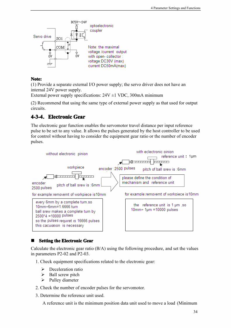
4-3-44-3-44-3-44-3-4.ElectronicElectronicElectronicElectronic GearGearGearGearThe electronic gear function enables the servomotor travel distance per input referencepulse to be set to any value. It allows the pulses generated by the host controller to be usedfor control without having to consider the equipment gear ratio or the number of encoderpulses.
���� SettingSettingSettingSetting thethethethe ElectronicElectronicElectronicElectronic GearGearGearGear
Calculate the electronic gear ratio (B/A) using the following procedure, and set the valuesin parameters P2-02 and P2-03.
1. Check equipment specifications related to the electronic gear:
� Deceleration ratio� Ball screw pitch� Pulley diameter
2. Check the number of encoder pulses for the servomotor.
3. Determine the reference unit used.
A reference unit is the minimum position data unit used to move a load (Minimum

4 Parameter Settings and Functions
35
unit of reference from the host controller).� Reference unit can be 0.1in or 0.01in or 0.01mm or 0.001mm, etc.� A reference unit of one pulse moves the load by one reference unit.� When the reference unit is 1µm, if a reference of 50000 units is input, the load
moves 50mm (1.97in)(50000 × 0.001mm = 50mm).
4. Determine the load travel distance per load shaft revolution in reference units.
Travel distance per load shaft revolution= Travel distance per load shaft revolution / Reference Unit
When the ball screw pitch is 0.20in (5mm) and the reference unit is 0.00004in (0.001mm),travel distance per load shaft revolution is 0.20/0.00004 = 5000(reference units).
5. Electronic gear ratio is given as: (B/A)
If the gear ratio of the motor and the load shaft is given as: (m/n)where m is the rotation of the motor and n is the rotation of the load shaft,
Note:Note:Note:Note:Make sure the electronic gear ratio satisfies the following condition:
The servo driver will not work properly if the electronic gear ratio exceeds thisrange. In that case, modify either the load configuration or the reference unit.
6. Set the parameters.
Reduce the electronic gear ratio to the lower terms so that both A and B are integerssmaller than 65535, then set A and B in the respective parameters:
���� ElectronicElectronicElectronicElectronic GearGearGearGear SettingSettingSettingSetting ExamplesExamplesExamplesExamples
The following examples show electronic gear settings for different load mechanisms.
((((1111)))) BallBallBallBall ScrewsScrewsScrewsScrews
Ball Screw Disc Table Belt and Pulley
Parameter Name Unit SettingRange
DefaultSetting
Control Mode
P2-02 Electronic Gear Ratio(Numerator) - 1~65535 1 Position Control
P2-03 Electronic Gear Ratio(Denominator) - 1~65535 1 Position Control

4 Parameter Settings and Functions
36
((((2222)))) CircularCircularCircularCircular TablesTablesTablesTables
((((3333)))) BeltsBeltsBeltsBelts andandandand PulleysPulleysPulleysPulleys
4-3-54-3-54-3-54-3-5.DigitalDigitalDigitalDigital ReferenceReferenceReferenceReference SpeedSpeedSpeedSpeed ControlControlControlControlThis function provides a method for easy speed control. It allows the user to initially setthree different motor speeds with parameters, and then select one of the speeds externallyusing a input signal.
���� UsingUsingUsingUsing DigitalDigitalDigitalDigital ReferenceReferenceReferenceReference SpeedSpeedSpeedSpeed ControlControlControlControl
Parameter P2-02 10000P2-03 6000
Parameter P2-02 30000P2-03 3600
Parameter P2-02 20000P2-03 15700

4 Parameter Settings and Functions
37
Follow steps 1 to 3 below to use digital reference speed control.
1. Set digital reference speed control as shown below.
Meanings for the following signals change when the digital reference speed control is used.
Note:Note:Note:Note: 0: OFF, 1: ON
2. Set the motor speeds with the following parameters.
If the setting is higher than the maximum motor speed of the servomotor, then theservomotor will rotate at its maximum speed.Speed selection input signals /SPD-A and /SPD-B and the rotation direction selectionsignal /SPD-D enable the servomotor to run at the preset speeds.
3. Set the soft start time.
The servo driver internal speed reference controls speed by applying this acceleration anddeceleration setting.Smooth speed control can be performed by entering a progressive speed reference or usingcontact input speed control. Set each constant to 0 for normal speed control or positioncontrol.Set each parameter to the following time intervals.� P3-05: Time interval from when the servomotor accelerates from 0 to rated speed.� P3-06: Time interval from when the servomotor decelerates from rated speed to 0.
The following example shows operation by digital reference speed control. Using the softstart function reduces physical shock when the speed is changing.
Parameter Name SettingRange
DefaultSetting Setting
P0-00 Main Mode 0 0 0P0-01 Sub Mode 1 0~7 0 3: Speed (Digital Reference)P0-02 Sub Mode 2 0~7 0
Sub Mode Description Input Signal
Speed(DigitalReference)
Using DigitalReference SpeedControl
/SPD-D /SPD-A /SPD-B Speed Reference
Direction0: Forward1: Reverse
0 0 00 1 V-REF1 (P3-01)1 1 V-REF2 (P3-02)1 0 V-REF3 (P3-03)
Parameter Name Unit SettingRange
DefaultSetting
ControlMode
P3-01 Speed 1 (V-REF1)Digital Reference Speed Control rpm -5000~+5000 100 Speed
Control
P3-02 Speed 2 (V-REF2)Digital Reference Speed Control rpm -5000~+5000 200 Speed
Control
P3-03 Speed 3 (V-REF3)Digital Reference Speed Control rpm -5000~+5000 300 Speed
Control
Parameter Name Unit SettingRange
DefaultSetting
Control Mode
P3-05 Acceleration Time ms 0~65535 0 Speed ControlP3-06 Deceleration Time ms 0~65535 0 Speed Control

4 Parameter Settings and Functions
38
4-3-64-3-64-3-64-3-6.TorqueTorqueTorqueTorque ControlControlControlControlDS2 series servo driver can control torque in Torque(Digital Reference) Control Mode.Set the following parameter to select the torque(digital reference) control.
1. Control torque according to the digital reference.
2. Speed limit during torque control.
4-3-74-3-74-3-74-3-7.EncoderEncoderEncoderEncoder ZZZZ SignalSignalSignalSignal OutputOutputOutputOutputEncoder Z signal can be output in DS2 series servo driver. Set the following parameter toenable the output function.
※1: Default setting of DS2-21P5 is “n.0013”.
Z signal outputs as a single pulse. The width of the pulse is about 1.5ms regardless of thespeed of the motor.
Parameter Name Setting Range Default Setting SettingP0-00 Main Mode 0 0 0P0-01 Sub Mode 1 0~7 0 1: Torque(Digital
Reference)P0-02 Sub Mode 2 0~7 0
Parameter Name Unit SettingRange
Default Setting
P4-09 Torque Digital Reference 1% -300~300 0
Parameter Name Unit SettingRange
Default Setting
P4-07 Speed Limit during Torque Control rpm 0~5000 2000
Parameter Name Unit Setting Range DefaultSetting
P5-38 Encoder Z Signal Assignment - n.0000~n.0012※1 n.0000

4 Parameter Settings and Functions
39
Origin Signal On Encoder Z
When P5-38=n.0001Wave On SO1
When P5-38=n.0011Wave On SO1
1ms~2msTypical 1.5ms
4-44-44-44-4.SettingSettingSettingSetting UpUpUpUp thethethethe ServoServoServoServo DriverDriverDriverDriver
This section describes the procedure for setting parameters to operate the DS series servodriver.
4-4-14-4-14-4-14-4-1.IndicatingIndicatingIndicatingIndicating ControlControlControlControl ModeModeModeMode2 sub modes stand for 2 control modes, changing with input signal /C-SEL.Sub mode 1 is selected when /C-SEL is OFF, whereas sub mode 2 is selected when /C-SEL is ON.
Input signal /C-SEL can be input from any input terminal by setting the followingparameter.
Default setting is n.0000 and is fixed to OFF.
Assign /C-SEL to any of the input terminals to enable change control mode function.
Please refer to 4-4-2(Input Signal Assignment) to know more about setting this parameter.※1: Setting range of DS2-21P5 is “n.0000~n.0014”.
Set the following parameters to change the control mode.
Description of Control Modes
0: Idle
Parameter Name Unit SettingRange
DefaultSetting
Control Mode
P5-20 Control ModeSelection -
n.0000~n.0012※1
n.0000 Position Control, SpeedControl and Torque Control
Parameter Name Unit Setting Range Default SettingP0-00 Main Mode - 0 0P0-01 Sub Mode 1 - 0~7 0P0-02 Sub Mode 2 - 0~7 0
Main Mode Sub Mode 1 Sub Mode 2
0: Normal
0: Idle 0: Idle1: Torque (Digital Reference) 1: Torque (Digital Reference)2: Torque (Analog Reference) 2: Torque (Analog Reference)3: Speed (Digital Reference) 3: Speed (Digital Reference)4: Speed (Analog Reference) 4: Speed (Analog Reference)5: Position (Digital Reference) 5: Position (Digital Reference)6: Position (Pulse Reference) 6: Position (Pulse Reference)7: Speed (Pulse Reference) 7: Speed (Pulse Reference)

4 Parameter Settings and Functions
40
Idle mode. Enable the motor but keep still.
1: Torque (Digital Reference)
Digital reference Torque Control. Please refer to 4-3-6 ”Torque Control”.
2: Torque (Analog Reference)
Analog reference Torque Control. DS2 series doesn’t have this mode.
3: Speed (Digital Reference)
Digital Reference Speed Control. It allows the user to initially set three differentmotor speeds with parameters, and then select one of the speeds externally using a inputsignal. Please refer to 4-3-5 ” Digital Reference Torque Control”.
4: Speed (Analog Reference)
Analog Reference Speed Control. DS2 series doesn’t have this mode.
5: Position (Digital Reference)
Digital Reference Position Control. It is still in construct.
6: Position (Pulse Reference)
Pulse Reference Position Control. Please refer to 4-3-2 “Position Reference”.
7: Speed (Pulse Reference)
Pulse Frequency Reference Speed Control. Speed reference is in direct proportion tothe frequency of input pulse string, and the reference is independent of the total number ofthe pulse string. Please refer to 4-3-1 “Speed Reference”.
Note: Do not set sub mode to 2 (Torque (Analog Reference)) or 4 (Speed (AnalogReference)) for DS2 series servo driver cannot receive analog reference.
4-4-24-4-24-4-24-4-2.InputInputInputInput SignalSignalSignalSignal AssignmentAssignmentAssignmentAssignmentDescriptionDescriptionDescriptionDescription forforforfor inputinputinputinput signalsignalsignalsignal assignmentassignmentassignmentassignmentEvery signal assignment parameter is composed of 4 part(from MSB to LSB):
Input Terminal (SI1~SI4)
Reverse Signal Or Not: 0 Not Reversed;
1: ReversedNNNNote:ote:ote:ote:For example, when P5-12 is set to n.0013, the /POT signal is input from SI3 terminal andit is reversed, which means when the SI3=24V or not connected, /POT = ON and theforward revolving is prohibited; when the SI3=0V, /POT = OFF and the forward revolvingis allowed.If two different signals are assigned to the same termianl, both signals are controlled byone terminal.
4-4-34-4-34-4-34-4-3.OutOutOutOutputputputput SignalSignalSignalSignal AssignmentAssignmentAssignmentAssignmentDescriptionDescriptionDescriptionDescription forforforfor outputoutputoutputoutput signalsignalsignalsignal assignmentassignmentassignmentassignmentEvery signal assignment parameter is composed of 4 part(from MSB to LSB):
3 12 0

4 Parameter Settings and Functions
41
Output Terminal (SO1~SO4)
Reverse Signal Or Not: 0 Not Reversed;
1: Reversed
Note:Note:Note:Note:
(1) Signals are output with OR logic when multiple signals are assigned to the same outputterminal(/Z is special).(2) When /Z signal is assigned to a terminal with other ordinary signals, /Z signal will takeentire possession of that terminal, and other signals assigned to the same terminal cannotbe output correctly.
4-4-44-4-44-4-44-4-4.JogJogJogJog SpeedSpeedSpeedSpeedUse the following parameter to modify speed when operating the servomotor from thepanel or by software.
If the setting is higher than the maximum motor speed of the servomotor, then theservomotor will rotate at its maximum speed.
4-54-54-54-5.SettingSettingSettingSetting StopStopStopStop FunctionsFunctionsFunctionsFunctions
This section describes the procedure used to stop the servomotor properly.
4-5-14-5-14-5-14-5-1.ZeroZeroZeroZero ClampClampClampClamp (/ZCLAMP)(/ZCLAMP)(/ZCLAMP)(/ZCLAMP)���� ZeroZeroZeroZero ClampClampClampClamp FunctionFunctionFunctionFunction
The zero clamp function is used for systems where the host controller does not form aposition loop for the speed reference input. In other words, this function is used to stopand lock the servomotor even when the input voltage of speed reference is not 0. Aninternal position loop is temporarily formed to clamp the servomotor within one pulsewhen the zero clamp function is turned ON. Even if the servomotor is forcibly rotated byexternal force, it will still return to the zero clamp position.
���� ParameterParameterParameterParameter SettingSettingSettingSetting
Set the following parameter so that the input signal /ZCLAMP can be used to enable ordisable the zero clamp function.
Default setting is n.0000 and is fixed to OFF.Assign /ZClamp to any of the input terminals to enable Zero Clamp Function.Please refer to 4-4-2(Input Signal Assignment) to know more about setting this parameter.※1: Setting range of DS2-21P5 is “n.0000~n.0014”.Zero clamp is performed when all the following conditions are satisfied:� Speed control is selected (Sub Mode=3 or 4)� /ZCLAMP=ON。� Speed reference drops below the setting level of P5-01.
Parameter Name Unit Setting Range Default SettingP3-04 Jog Speed rpm 0~1000 100
Parameter Name Unit Setting Range DefaultSetting
ControlMode
P5-21 Zero Clamp - n.0000~n.0012※1 n.0000 SpeedControl
3 12 0

4 Parameter Settings and Functions
42
4-64-64-64-6.IOIOIOIO SignalsSignalsSignalsSignals ControlControlControlControl
This section describes the procedure for using I/O signals of the servo driver.
4-6-14-6-14-6-14-6-1.AlarmAlarmAlarmAlarmOutputOutputOutputOutput (/ALM)(/ALM)(/ALM)(/ALM)The basic procedure for connecting alarm output signals is described below.
An external I/O power supply must be provided by the user separately because there is nointernal 24V power supply in the servo driver.
/ALM is set to ON when a servo driver alarm is raised.
Form an external circuit so this alarm output (ALM) turns OFF the servo driver.
Set the following parameter so that the output signal /ALM can be used to output to anyoutput terminal.
Signal Description Control Mode/ALM Alarm Output Position Control, Speed Control and Torque Control
Signal Signal Status Reversed Or Not Terminal Status Description
/ALMON
Direct Output On between SO and COMAlarm State
Reverse Output Off between SO and COM
OFFDirect Output On between SO and COM
Normal StateReverse Output Off between SO and COM
Parameter Name Unit Setting Range Default SettingP5-37 Alarm Signal Assignment - n.0000~n.0012※1 n.0002

4 Parameter Settings and Functions
43
Default setting is n.0002 and is output between SO2 and COM.
Please refer to 4-4-3(Output Signal Assignment) to know more about setting thisparameter.※1: Setting range of DS2-21P5 is “n.0000~n.0013”.
When a servo alarm (/ALM) raised, eliminate the cause of the alarm and set the /ALM-RST input signal to ON to reset the alarm.
The alarm reset signal is used to reset a servo alarm.Alarms can also be reset using a panel or digital operator.
4-6-24-6-24-6-24-6-2.ServoServoServoServo ONONONON InputInputInputInput (S-ON)(S-ON)(S-ON)(S-ON)There are two method to input Servo On signal, 1, input from a terminal, 2, automaticallyservo on after power on.
���� InputInputInputInput FromFromFromFrom TerminalTerminalTerminalTerminal
The basic use and wiring procedure for the Servo ON (/S-ON) input signal is describedbelow. Use this signal to forcibly turn OFF the servomotor from the host controller.
Do not use the Servo ON (/S-ON) signal to start or stop the motor. Always use an inputreference signal to start or stop the servomotor.
���� AAAAutomaticallyutomaticallyutomaticallyutomatically SSSServoervoervoervo OOOOnnnn AAAAfterfterfterfter PPPPowerowerowerower OOOOnnnn(Not(Not(Not(Not UseUseUseUse /S-ON/S-ON/S-ON/S-ON Signal)Signal)Signal)Signal)
Set the parameter P5-10 to n.0010 to make servo driver automatically servo on after poweron. Please refer to 4-1-6.
4-6-34-6-34-6-34-6-3.PositioningPositioningPositioningPositioning CompletedCompletedCompletedCompleted OutputOutputOutputOutput (/(/(/(/COINCOINCOINCOIN))))The basic use and wiring procedure for the positioning completed (/COIN) outputSignal is described below. This signal is output to indicate that servomotor positioning iscompleted.
Signal Description Control Mode/ALM-RST Alarm Reset Position Control, Speed Control and Torque Control
Signal Description Control Mode/S-ON Servo On Position Control, Speed Control and Torque Control

4 Parameter Settings and Functions
44
This signal indicates that servomotor movement has completed a positioning. The hostcontroller uses the signal as an interlock to confirm that positioning is completed.
Set the following parameter so that the output signal /COIN can be used to output to anyoutput terminal.
Default setting is n.0001 and is output between SO1 and COM.
Please refer to 4-4-3(Output Signal Assignment) to know more about setting thisparameter.※1: Setting range of DS2-21P5 is “n.0000~n.0013”.
The following parameter is used to set the number of error pulses and to adjust the outputwidth of the positioning completed signal.
When in position control mode and the error between position reference and actualposition drops below the level indicated by P5-00, output signal /COIN is turned to ON,which means the positioning is completed. Default setting of P5-00 is 7 ref units. /COIN isfixed to OFF in speed control and torque control.
Signal Description Control Mode/COIN Positioning Completed Position Control
Signal Signal Status Reversed Or Not Terminal Status Description
/COINON
Direct Output On between SO and COM PositioningCompletedReverse Output Off between SO and COM
OFFDirect Output On between SO and COM
In PositioningReverse Output Off between SO and COM
Parameter Name Unit Setting Range Default Setting
P5-28 /COIN Signal Assignment -n.0000~n.0012※1 n.0001
Parameter Name Unit SettingRange
DefaultSetting Control Mode
P5-00 PositioningCompleted Width
refunit 0~250 7 Position Control

4 Parameter Settings and Functions
45
4-6-44-6-44-6-44-6-4.SpeedSpeedSpeedSpeed CoincidenceCoincidenceCoincidenceCoincidence OutputOutputOutputOutput (/(/(/(/V-CMPV-CMPV-CMPV-CMP))))The basic use and wiring procedures for the speed coincidence (/V-CMP) output signal,used to indicate a match with the speed reference, are described below. The host controlleruses the signal as an interlock.
Set the following parameter so that the output signal /V-CMP can be used to output to anyoutput terminal.
Default setting is n.0000 and is not output to terminal.Please refer to 4-4-3(Output Signal Assignment) to know more about setting thisparameter.※1: Setting range of DS2-21P5 is “n.0000~n.0013”.
The following parameter is used to set the number of error pulses and to adjust the outputwidth of the speed coincidence signal.
When in speed control and the error between speed reference and speed feedback dropsbelow the level indicated by P5-03, output signal /V-CMP is turned to ON, which meansthe current speed matches the speed reference.
4-6-54-6-54-6-54-6-5.RotationRotationRotationRotation DetectionDetectionDetectionDetection OutputOutputOutputOutput (/(/(/(/TGONTGONTGONTGON))))The basic use and wiring procedures for the Rotation Detection (/TGON) output signal aredescribed below. The signal can be activated to indicate that the servomotor is currentlyoperating. It is used as an external interlock.
Signal Description Control Mode/V-CMP Speed Coincidence Output Speed Control
Signal Signal Status Reversed Or Not Terminal Status Description
/V-CMPON
Direct Output On between SO and COM SpeedcoincidesReverse Output Off between SO and COM
OFFDirect Output On between SO and COM Speed does
not coincideReverse Output Off between SO and COM
Parameter Name Unit Setting Range Default SettingP5-29 /V-CMP Signal Assignment - n.0000~n.0012※1 n.0000
Parameter Name Unit Setting Range Default Setting
P5-03 Speed Coincidence SignalOutput Width rpm 1~250 10

4 Parameter Settings and Functions
46
Parameter: P5-02 (Rotation Detection Speed Level)
Set the following parameter so that the output signal /TGON can be used to output to anyoutput terminal.
Default setting is n.0000 and is not output to terminal.Please refer to 4-4-3(Output Signal Assignment) to know more about setting thisparameter.※1: Setting range of DS2-21P5 is “n.0000~n.0013”.
The following parameter is used to set the number of error pulses and to adjust the outputwidth of the rotation detection signal.
If speed exeeds the level indicated by P5-02, /TGON signal is turned to ON, which meansthe motor is rotating.
4-6-64-6-64-6-64-6-6.ServoServoServoServo ReadyReadyReadyReady OutputOutputOutputOutput (/(/(/(/S-RDYS-RDYS-RDYS-RDY))))The basic use and wiring procedures for the Servo Ready (/S-RDY) output signal aredescribed belowServo Ready means there are no servo alarms and the main circuit power supply is turnedON.
Signal Description Control Mode
/TGON Rotation Detection Output Position Control, Speed Control andTorque Control
Signal Signal Status Reversed Or Not Terminal Status Description
/TGONON
Direct Output On between SO and COM Motor isoperatingReverse Output Off between SO and COM
OFFDirect Output On between SO and COM Motor is not
operatingReverse Output Off between SO and COM
Parameter Name Unit Setting Range Default SettingP5-30 /TGON Signal Assignment - n.0000~n.0012※1 n.0000
Parameter Name Unit Setting Range Default SettingP5-02 Rotation Detection Speed Level rpm 1~1000 20

4 Parameter Settings and Functions
47
This signal indicates that the servo driver has completed all preparations and is ready toreceive the Servo ON signal.
Set the following parameter so that the output signal /TGON can be used to output to anyoutput terminal.
For DS2-20P4 and DS2-20P7, default setting is n.0000 and is not output to terminal.For DS2-21P5, default setting is n.0003 and is output between SO3 and COM.Please refer to 4-4-3(Output Signal Assignment) to know more about setting thisparameter.※1: Setting range of DS2-21P5 is “n.0000~n.0013”.
4-6-74-6-74-6-74-6-7.NearNearNearNear OutputOutputOutputOutput (/(/(/(/NEARNEARNEARNEAR))))The basic use and wiring procedures for the near (/NEAR) output signal are describedbelow. The signal is generally output together with the positioning completed signal(/COIN), and it is used to indicate the servomotor is close to completing positioning.
The host controller can use the /NEAR signal to prepare the next motion sequence before
Signal Description Control Mode
/S-RDY Servo Ready Output Position Control, Speed Control and TorqueControl
Signal Signal Status Reversed Or Not Terminal Status Description
/S-RDYON
Direct Output On between SO and COM Servo isreadyReverse Output Off between SO and COM
OFFDirect Output On between SO and COM Servo is not
readyReverse Output Off between SO and COM
Parameter Name Unit Setting Range Default SettingP5-31 /S-RDY Signal Assignment - n.0000~n.0012※1 n.0000
Signal Description Control Mode/NEAR Near Output Position Control

4 Parameter Settings and Functions
48
receiving the positioning completed signal. This reduces the time required to complete thedesired motion profile.
Set the following parameter so that the output signal /NEAR can be used to output to anyoutput terminal.
Default setting is n.0000 and is not output to terminal.Please refer to 4-4-3(Output Signal Assignment) to know more about setting thisparameter.
※1: Setting range of DS2-21P5 is “n.0000~n.0013”.
The following parameter is used to set the number of error pulses and to adjust the outputwidth of the positioning nearing signal.
Generally set the near signal width higher than the positioning completed width. Pleaserefer to 4-6-3 “Positioning Completed Output (/COIN)”.
4-6-84-6-84-6-84-6-8.WarningWarningWarningWarning OutputOutputOutputOutput ((((WARNWARNWARNWARN))))The basic use and wiring procedure for the warning (/WARN) output signal are givenbelow.When the servomotor is overloading, /WARN signal is turned to ON. If it is stilloverloading for a definite time, alram is raised and /ALARM signal is turned to ON.
Signal Signal Status Reversed Or Not Terminal Status Description
/NEAR
ONDirect Output On between SO and COM Near to the
positionreferenceReverse Output Off between SO and COM
OFFDirect Output On between SO and COM Not near to
the positionreferenceReverse Output Off between SO and COM
Parameter Name Unit Setting Range Default SettingP5-36 /NEAR Signal Assignment - n.0000~n.0012※1 n.0000
Parameter Name Unit Setting Range Default Setting
P5-04 Positioning NearingSignal Width ref unit 0~10000 50

4 Parameter Settings and Functions
49
Set the following parameter so that the output signal /WARN can be used to output to anyoutput terminal.
Default setting is n.0000 and is not output to terminal.Please refer to 4-4-3(Output Signal Assignment) to know more about setting thisparameter.
※1: Setting range of DS2-21P5 is “n.0000~n.0013”.
4-74-74-74-7.SmoothSmoothSmoothSmooth OperationOperationOperationOperation
This section provides technical information on the smooth operation of servomotors.
4-7-14-7-14-7-14-7-1.SmoothingSmoothingSmoothingSmoothingThe smoothing function applies a filter inside the servo driver to a constant-frequencyreference input so that acceleration and deceleration can be as constant as possible. To usethis function, set the following parameters.Use the following parameter to set the type of filter to be applied.
Either an acceleration/deceleration or average movement filter can be selected.
The time constant and time for these filters are set in the following parameters.
Signal Description Control Mode/WARN Warning Output Position Control, Speed Control and Torque Control
Signal Signal Status Reversed Or Not Terminal Status Description
/WARNON
Direct Output On between SO and COMWarning
Reverse Output Off between SO and COM
OFFDirect Output On between SO and COM
NormalReverse Output Off between SO and COM
Parameter Name Unit Setting Range Default SettingP5-35 /WARN Signal Assignment - n.0000~n.0012※1 n.0000
Parameter Name Unit Setting Range Default Setting Control Mode
P2-01 Position ReferenceFilter Type - 0, 1 0 Position
Control
Setting Description0 Enables acceleration/deceleration filter.1 Enables average movement filter.
Parameter Name Unit SettingRange
DefaultSetting
ControlMode
P2-04 Position Reference FilterTime Contant ms 0~100 0 Position
Control

4 Parameter Settings and Functions
50
Position reference filter is effective to both position control(Pulse Reference) and speedcontrol(Pulse Reference).
4-7-24-7-24-7-24-7-2.SoftSoftSoftSoft StartStartStartStart FunctionFunctionFunctionFunctionThe soft start function adjusts progressive speed reference input inside the servo driver sothat acceleration and deceleration can be as constant as possible. To use this function, setthe following parameters.
In the servo driver, a speed reference is re-calculated by the acceleration or decelerationvalue set in P3-05 or P3-06 to provide speed control.The soft start function enables smooth speed control when progressive speed referencesare input or when Digital Reference Speed Control is used. Set both P3-05 and P3-06 to“0” for normal speed control.
Set these parameters as follows:• P3-05: Time interval from when the servomotor accelerates from 0 to rated speed.• P3-06: Time interval from when the servomotor decelerates from rated speed to 0.
4-84-84-84-8.GainGainGainGain AdjustmentsAdjustmentsAdjustmentsAdjustments
This section describes information on the basic rules of gain adjustments in the servodriver, adjustment methods in a variety of cases, and reference set values.
4-8-14-8-14-8-14-8-1.ServoServoServoServo GainGainGainGain ParametersParametersParametersParameters���� SettingSettingSettingSetting SpeedSpeedSpeedSpeed LLLLoopoopoopoop GGGGainainainain
Set the following speed loop related parameters as required.
The higher the speed loop gain, or the smaller the speed loop integral time constant value,the faster the speed control response will be. There is, however, a certain limit dependingon machine characteristics.
Parameter Name Unit Setting Range Default Setting Control ModeP3-05 Acceleration Time ms 0~65535 0 Speed ControlP3-06 Deceleration Time ms 0~65535 0 Speed Control
Parameter Name Unit SettingRange
DefaultSetting Control Mode
P1-00 Speed Loop Gain Hz 1~500 100 Position Control,Speed Control
P1-01 Speed Loop IntegralTime Contant 0.1ms 1~5000 400 Position Control,
Speed Control

4 Parameter Settings and Functions
51
���� SettingSettingSettingSetting PositionPositionPositionPosition LoopLoopLoopLoop GainGainGainGain
Set the following position loop-related parameter as required.
The higher the position loop gain, the smaller the position control error will be. There is,however, a certain limit depending on machine characteristics.
Set in this parameter the error pulse level at which a position error pulse overflow alarm israised.
When Position Error Overflow Level is set to 0, the alarm is never raised.
If the machine permits only a small position loop gain value to be set in P1-02, anoverflow alarm may arise during high speed operation. In this case, increase the value setin this parameter to avoid unnecessary alarms.
4-8-24-8-24-8-24-8-2.UsingUsingUsingUsing ProportionalProportionalProportionalProportional ControlControlControlControl (/(/(/(/P-CONP-CONP-CONP-CON))))Input signal /P-CON serves as a PI/P control changeover switch.PI control: Proportional/integral control.P control: Proportional control.
���� MethodsMethodsMethodsMethods forforforfor UsingUsingUsingUsing ProportionalProportionalProportionalProportional ControlControlControlControl
Set the following parameter so that the input signal /P-CON can be used to proportionalcontrol.
Default setting is n.0000 and is fixed to OFF.
Parameter Name Unit SettingRange
DefaultSetting Control Mode
P1-02 Position Loop Gain 1/s 1~2000 30 Position Control
Parameter Name Unit SettingRange
DefaultSetting Control Mode
P5-05 Position ErrorOverflow Level 256 ref units 0~65535 1000 Speed Control
Parameter Name Unit Setting Range DefaultSetting Control Mode
P5-11 /P-CON SignalAssignment -
n.0000~n.0012※1 n.0000 Position Control,
Speed Control
This gain setting is also valid for zero clamp operation.

4 Parameter Settings and Functions
52
Assign /P-CON to any of the input terminals to use proportional control.Please refer to 4-4-2(Input Signal Assignment) to know more about setting this parameter.
Proportional control can be used in the following two ways.1, When operation is performed by sending speed references from the host controller tothe servo driver, the host controller can selectively use P control mode for particularconditions only. This method can suppress overshooting and shorten setting time.2, If PI control mode is used when the speed reference has a reference offset, the motormay rotate at a very slow speed and fail to stop even if 0 is specified as a speed reference.In this case, use P control mode to stop the motor.
4-8-34-8-34-8-34-8-3.GainGainGainGain SelectionSelectionSelectionSelection (/(/(/(/G-SELG-SELG-SELG-SEL))))Gain selection is a function that can switch gain during the motor is running.For example, if gain needs to be changed when motor is stopped, set different gain groupand use a external signal to select the group of gain.
Set the following parameter so that the input signal /G-SEL can be used to select gain.
Default setting is n.0000 and is fixed to OFF.Assign /G-SEL to any of the input terminals to select gain.Please refer to 4-4-2(Input Signal Assignment) to know more about setting this parameter.
The first group of gain is selected when /G-SEL is OFF, and the second group of gain isselected when /G-SEL is ON.
Parameter Name Unit Setting Range DefaultSetting Control Mode
P5-23 /G-SEL SignalAssignment - n.0000~n.0012※1 n.0000 Position Control,
Speed Control
/G-SEL Signal OFF ONSpeed Loop Gain P1-00 is selected. P1-04 is selected.Speed Loop Integral Time Contant P1-01 is selected. P1-05 is selected.Position Loop Gain P1-02 is selected. P1-06 is selected.

5 Using Digital Panel
53
5555 UsingUsingUsingUsing DigitalDigitalDigitalDigital PanelPanelPanelPanelThis chapter describes the basic operation of the digital panel and the features it offers. Allparameter settings and motor operations can be executed by simple, convenient operations.Operate the digital panel as you read through this chapter.
5-15-15-15-1.BasicBasicBasicBasic OperationOperationOperationOperation
This section provides information on the basic operation of the digital panel for settingoperating conditions.
5-1-15-1-15-1-15-1-1.FunctionsFunctionsFunctionsFunctions OfOfOfOf DigitalDigitalDigitalDigital PanelPanelPanelPanelThe digital panel can be used for parameter settings, operating references, and statusdisplays.
� 5 7Seg-LEDs: Displaying parameter settings, status or alarm.� Power LED POWER: The LED is on when the servo driver is powered on.� Charge LED CHARGE: The LED is on when the main circiut is powered on. When
the power of main circiut is off, electric charge still remains in the capacitors, and atthis time DO NOT touch servo driver.
This section provides information on the keys and their functions available from the initialdisplays.
5-1-25-1-25-1-25-1-2.BasicBasicBasicBasic ModeModeModeMode SelectionSelectionSelectionSelectionThe basic mode selection of the digital panel is used for indicating the status of the servodriver in operation and setting a variety of parameters and operation references.The status display, auxiliary function, parameter setting, and monitor modes are the basicmodes. As shown below, the mode is selected in the following order by pressing the key.
Key Name FunctionSTATUS/ESC Press: Status switch, status return
INC Press: Increase the value; Press and hold: Increase the valuecontinuously
DEC Press: Decrease the value; Press and hold: Decrease the valuecontinuously
ENTER Press: Shift the editing digit; Press and hold: Enter a status, Enter
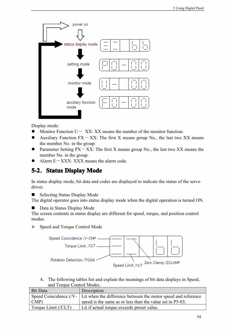
5 Using Digital Panel
54
Display mode:� Monitor Function U- XX: XX means the number of the monitor function.� Auxiliary Function FX-XX: The first X means group No., the last two XX means
the member No. in the group.� Parameter Setting PX-XX: The first X means group No., the last two XX means the
member No. in the group.� Alarm E-XXX: XXX means the alarm code.
5-25-25-25-2.StatusStatusStatusStatus DisplayDisplayDisplayDisplay ModeModeModeMode
In status display mode, bit data and codes are displayed to indicate the status of the servodriver.
� Selecting Status Display ModeThe digital operator goes into status display mode when the digital operation is turned ON.
� Data in Status Display ModeThe screen contents in status display are different for speed, torque, and position controlmodes.
� Speed and Torque Control Mode
A. The following tables list and explain the meanings of bit data displays in Speed,and Torque Control Modes.
Bit Data DescriptionSpeed Coincidence (/V-CMP)
Lit when the difference between the motor speed and referencespeed is the same as or less than the value set in P5-03.
Torque Limit (/CLT) Lit if actual torque exceeds preset value.

5 Using Digital Panel
55
B. The following tables list and explain the meanings of code displays in Speed, andTorque Control Modes.
� Position Control Mode
A. The following tables list and explain the meanings of bit data displays in Speed,and Torque Control Modes.
B. The following tables list and explain the meanings of code displays in Speed, andTorque Control Modes.
Forward Torque Limit: P4-02Reverse Torque Limit: P4-03
Rotation Detection(/TGON)
Lit if speed exeeds the level indicated by P5-02.Rotation Detection Speed Level: P5-02(Unit: rpm)
Zero Clamp(/ZCLAMP) Lit if /ZCLAMP signal is ON.
Speed Limit (/VLT) Lit if actual speed exceeds preset value.Speed Limit during Torque Control: P4-07
Code DescrptionStandbyServo OFF (motor power OFF)
RunServo ON (motor power ON)
Forward Run ProhibitedP-OT is OFF. Please refer to 4-2-2 “Overtravel Limit”
Reverse Run ProhibitedN-OT is OFF. Please refer to 4-2-2 “Overtravel Limit”
Bit Data DescriptionPositioningCompleted (/COIN)
Lit if error between position reference and actualmotor position is below the value set in P5-00.
Near (/NEAR) Lit if error between position reference and actualmotor position is below the value set in P5-04.
Rotation Detection(/TGON)
Lit if speed exeeds the level indicated by P5-02.Rotation Detection Speed Level: P5-02(Unit: rpm)
Code DescrptionStandbyServo OFF (motor power OFF)
RunServo ON (motor power ON)
Forward Run ProhibitedP-OT is OFF. Please refer to 4-2-2 “Overtravel

5 Using Digital Panel
56
5-35-35-35-3.MonitorMonitorMonitorMonitor ModeModeModeMode
The Monitor Mode can be used for monitoring the reference values, I/O signal status, andservo driver internal status.The monitor mode can be set during motor operation.
���� UsingUsingUsingUsing thethethethe MonitorMonitorMonitorMonitor ModeModeModeMode
The example below shows how to display 0, the contents of monitor number U-16.1. Press the STATUS/ESC key to select the monitor mode.
2. Press the INC or DEC key to select the monitor number U-16, and then press and holdENTER to enter the monitor mode..
3. The value 0 is now displayed.
This completes the example procedure for displaying 0, the contents of monitor numberU-16.4. Press STATUS/ESC key to return to the monitor number display
���� ContentsContentsContentsContents ofofofof MonitorMonitorMonitorMonitor ModeModeModeMode DisplayDisplayDisplayDisplay
Limit”Reverse Run ProhibitedN-OT is OFF. Please refer to 4-2-2“Overtravel Limit”
Number Monitor Display UnitU-00 Actual speed rpmU-01 Speed reference rpmU-02 Internal torque reference %U-03 Rotate angle (mechenism angle) 0.1°U-04 Rotate angle (electrical angle) 0.1°U-05 DC voltage VU-06 Module temperature 0.1℃U-07 Input reference pulse speed rpmU-08 Pulse error (0000~9999)*1 ref unitU-09 (0000~9999)*9999U-10 Rotate angle
(encoder pulse)(0000~9999)*1 encoder
pulseU-11 (0000~9999)*9999U-12 Input reference
pulse counter(0000~9999)*1 ref unitU-13 (0000~9999)*9999
U-14 Feedback referencepulse counter
(0000~9999)*1 ref unitU-15 (0000~9999)*9999U-16 Current position
(Accumulated)(0000~9999)*1 encoder
pulseU-17 (0000~9999)*9999U-18 Current 0.1AU-19 Analog input V-REF 0.01VU-20 Analog input T-REF 0.01VU-21 I/O signals statusU-22 I/O terminals status

5 Using Digital Panel
57
���� U-21U-21U-21U-21 displaysdisplaysdisplaysdisplays I/OI/OI/OI/O signalssignalssignalssignals statusstatusstatusstatus
The following diagram describes the input and output signals status displayed in U-21.
Diagram 1 Diagram 2
In diagram 1, LED4 and LED5 stand for input signals status, and LED1 and LED2 standfor output signals status. In diagram 2 there shows the segment No. of each LED.
� Input signals status
� Output signals status
���� U-22U-22U-22U-22 displaysdisplaysdisplaysdisplays I/OI/OI/OI/O terminalsterminalsterminalsterminals statusstatusstatusstatus。
The following diagram describes the input and output terminals status displayed in U-22.
Diagram 1 Diagram 2
In diagram 1, LED5 stands for input signals status, and LED2 stands for output signalsstatus. In diagram 2 there shows the segment No. of each LED.
Segment Description Segment DescriptionLED4_0 /SPD-A LED5_0 /S-ONLED4_1 /SPD-B LED5_1 /P-CONLED4_2 /C-SEL LED5_2 /P-OTLED4_3 /ZCLAMP LED5_3 /N-OTLED4_4 /INHIBIT LED5_4 /ALM-RSTLED4_5 /G-SEL LED5_5 /P-CLLED4_6 /CLR LED5_6 /N-CL
LED5_7 /SPD-D
Segment Description Segment DescriptionLED1_0 /NEAR LED2_0 /COINLED1_1 /ALM LED2_1 /V-CMPLED1_2 /Z LED2_2 /TGON
LED2_3 /S-RDYLED2_4 /CLTLED2_5 /VLTLED2_6 /BKLED2_7 /WARN
Input terminals Output terminalsSegment Description Segment DescriptionLED5_0 Input status on SI1 LED2_0 Output status on SO1LED5_1 Input status on SI2 LED2_1 Output status on SO2LED5_2 Input status on SI3 LED2_2 Output status on SO3LED5_3 Input status on SI4

5 Using Digital Panel
58
5-45-45-45-4.AAAAuxiliaryuxiliaryuxiliaryuxiliary FFFFunctionunctionunctionunction
This section describes how to apply the basic operations using the digital panel to run andadjust the servo driver.
5-4-15-4-15-4-15-4-1.CheckCheckCheckCheck SystemSystemSystemSystem InfomationInfomationInfomationInfomationPress the STATUS/ESC key to select the auxiliary function mode. Set the group No. to 0to check system information. Press INC or DEC key to select different member No., andpress and hold ENTER key to check current information. Press STATUS/ESC key toreturn.
The following table describes the meaning of each member No.
5-4-25-4-25-4-25-4-2.AAAAuxiliaryuxiliaryuxiliaryuxiliary RunRunRunRunModeModeModeModePress the STATUS/ESC key to select the auxiliary function mode. Set the group No. to 1to auxiliary run mode. Press INC or DEC key to select different member No., and pressand hold ENTER key to use current function. Press STATUS/ESC key to return.
1.1.1.1. JogJogJogJog (F1-00)(F1-00)(F1-00)(F1-00)
MMMMakeakeakeake suresuresuresure thatthatthatthat thethethethe motormotormotormotor shaftshaftshaftshaft isisisis detacheddetacheddetacheddetached fromfromfromfrommachinemachinemachinemachine beforebeforebeforebefore jogging!jogging!jogging!jogging!Press ENTER key to power on the motor (servo on). After doing this, press and hold INCkey for forward jogging, or DEC key for reverse jogging. Press STATUS/ESC key topower off the motor (servo off), and press STATUS/ESC key again to return.
4 different states are displayed in jogging.
2.2.2.2. TrialTrialTrialTrial OperationOperationOperationOperation (F1-01)(F1-01)(F1-01)(F1-01)
MMMMakeakeakeake suresuresuresure thatthatthatthat thethethethe motormotormotormotor shaftshaftshaftshaft isisisis detacheddetacheddetacheddetached fromfromfromfrommachinemachinemachinemachine beforebeforebeforebefore trialtrialtrialtrial operation!operation!operation!operation!
When servo driver is connected with non-oriented encoder line or power line, trialoperation must be run first to ensure that the encoder line or power line is connectedexactly correct.Set the display value to 1, and press and hold ENTER key to enter trial operation mode.There the panle displays:
Group No. DescriptionF0-** Checking system informationF1-** Auxiliary run modeF2-00 Setting motor codeF3-** Checking alarm informationF4-00 Reset parameters to defaultF5-00 External communication
Member No. Description Member No. DescriptionF0-00 Motor Code F0-01 Servo SeriesF0-02 Servo Model F0-03 Prod Date: YearF0-04 Prod Date: Month F0-05 Prod Date: DayF0-06 Software Version F0-07 Hardware Version
State Panel Display State Panel Display
Idle ForwardJogging
ServoON
ReverseJogging

5 Using Digital Panel
59
If correctly wired, the motor would rotate in 5 seconds in forward direction (fixed tocounter-clockwise), otherwise the motor would shock or viberate, raising an alarm forworse. In this case the power must be switched off immedietely and check the wiringagain.Press STATUS/ESC key to return.
3.3.3.3. CurrentCurrentCurrentCurrent OffsetOffsetOffsetOffset Auto-AdjustmentAuto-AdjustmentAuto-AdjustmentAuto-Adjustment (F1-02)(F1-02)(F1-02)(F1-02)
After the servo driver is updated to latest software version, or the motor does not revolvesmoothly after a long time run, a current offset auto-adjustment is recommended.Select F1-02 and enter current offset auto-adjustment function, and the panel displays“rEF” .Press ENTER key to start current offset auto-adjustment, and the panel displays blinking“rEF”.About 5 seconds later auto-adjustment is finished, and the panel displays “donE” toinform that the function is already executed out.Press STATUS/ESC key to return.
4.4.4.4. SpeedSpeedSpeedSpeed ReferenceReferenceReferenceReference Auto-AdjustmentAuto-AdjustmentAuto-AdjustmentAuto-Adjustment (F1-03)(F1-03)(F1-03)(F1-03)
Select F1-03 and enter speed reference auto-adjustment function, and the panel displays“rEF_o” .Press ENTER key to start speed reference auto-adjustment, and the panel displaysblinking “rEF_o”.About 1 second later auto-adjustment is finished, and the panel displays “donE” to informthat the function is already executed out.Press STATUS/ESC key to return.
5.5.5.5. TorqueTorqueTorqueTorque ReferenceReferenceReferenceReference Auto-AdjustmentAuto-AdjustmentAuto-AdjustmentAuto-Adjustment (F1-04)(F1-04)(F1-04)(F1-04)
Select F1-04 and enter torque reference auto-adjustment function, and the panel displays“rEF_o” .Press ENTER key to start torque reference auto-adjustment, and the panel displaysblinking “rEF_o”.About 1 second later auto-adjustment is finished, and the panel displays “donE” to informthat the function is already executed out.Press STATUS/ESC key to return.
6.6.6.6. ForceForceForceForce ServoServoServoServo OnOnOnOn (F1-05)(F1-05)(F1-05)(F1-05)
0: Force servo on function is disabled.1: Force servo on function is enabled.
5-4-3.5-4-3.5-4-3.5-4-3. SetSetSetSet MotorMotorMotorMotor CodeCodeCodeCodeSet group No. to 2 in auxiliary function and enter setting motor code function.One servo drive can be suitable to more than one servo motor with close power classesprinted on the nameplate of each motor. When user need to change a motor, please refer tothe Quick Guide to ensure the needed motor is supported by the driver.
The following steps show how to set motor code.1. Press STATUS/ESC key to select Auxiliary Function.2. Press INC or DEC key to set group No. to 2, and press ENTER key.3. Press and hold ENTER key to display current motor code.4. Press INC, DEC or ENTER key to modify the value displayed on the panel to select theneeded motor code and press and hold ENTER key to confirm.5. Restart servo driver to make this function effective.

5 Using Digital Panel
60
5-4-45-4-45-4-45-4-4.CheckCheckCheckCheck AlarmAlarmAlarmAlarm InformationInformationInformationInformationSet group No. to 2 in auxiliary function and enter checking alarm information function.The following steps show how to check alarm information.1. Press STATUS/ESC key to select Auxiliary Function.2. Press INC or DEC key to set group No. to 3, and press ENTER key.3. Press INC, DEC or ENTER key to modify the value displayed on the panel to select themember No..4. Press and hold ENTER key to display corresponding alarm information..
※1: F3-00=0 indicates that there is no alarm.※2: F3-01=0 indicates that there is no warn.
5-4-55-4-55-4-55-4-5.ResetResetResetReset ParametersParametersParametersParameters ToToToTo DefaultDefaultDefaultDefaultThe following steps show how to reset parameters to default.1. Press STATUS/ESC key to select Auxiliary Function.2. Press INC or DEC key to set group No. to 3, and press ENTER key.3. Press and hold ENTER key, and the panel displays “0” and is blinking.4. Set the value to 1. Press and hold ENTER key to confirm.5. Restart the driver and the parameters are all reset to default.
5-4-65-4-65-4-65-4-6.ExternalExternalExternalExternal CommunicationCommunicationCommunicationCommunicationSelect F5-00 to run External communication function in auxiliary function, and the paneldisplays “c-out” meaning the driver is ready to be controlled by host controller, andCOM1 is selected communicating with host controller. At this time the panel is disabledand host controller(mostly a PC) is used to debugging the servo driver. PressSTATUS/ESC key to return and panel recovers from “c-out” to monitoring.
5-55-55-55-5.PPPParameterarameterarameterarameter SSSSettingettingettingetting
The following steps show how to change a parameter.The parameter settings can be used to change parameter data. Check the permitted rangeof the parameters in 4-1 before changing the data.The example below shows how to change parameter P3-09 from 2000 to 3000.1. Press the STATUS/ESC key to select the parameter setting mode.
Member No. Description UnitF3-00 Current alarm code※1F3-01 Current warn code※2F3-02 Alarm/warn code 1 when alarm raisedF3-03 U phase current when alarm raised AF3-04 V phase current when alarm raised AF3-05 DC voltage when alarm raised VF3-06 IGBT temperature when alarm raised ℃F3-07 Speed when alarm raised rpmF3-08 Internal torque reference when alarm raised %
F3-09 V-REF when alarm raised VF3-10 T-REF when alarm raised VF3-11 Alarm/warn code 2 when alarm raisedF3-12 Alarm/warn code 3 when alarm raisedF3-13 Alarm/warn code 4 when alarm raisedF3-14 Alarm/warn code 5 when alarm raisedF3-15 Alarm/warn code 6 when alarm raisedF3-16 Alarm/warn code 7 when alarm raised

5 Using Digital Panel
61
2. At this time the second LED is blinking, and press INC or DEC key to set the group No.to 3. Press ENTER key to confirm.
3. At this time the last LED is blinking, and press INC or DEC key to set the member No.to 9. Press and hold ENTER key to confirm.
4. At this time the panel displays the value in P3-09, and the last decimal “0” is blinking.Press ENTER to left shift the blinking decimal. Press INC, DEC or ENTER key to modifythe value to 3000, and press and hold ENTER to confirm.
The parameter in P3-09 in changed from 2000 to 3000.Repeat steps 2 to 4 to change the setting again.5. Press STATUS/ESC key to return and change group No. or member No..
5-65-65-65-6.AlarmAlarmAlarmAlarm
Alarm mode is switched automatically when an alarm is raised in servo driver, and analarm code is displayed in form of “E-XXX”. If there is no alarm in servo driver, thealarm mode is not available to display. If there is one or more alarms, press ENTER key toreset the alarm. The servo alarm will be reset if power supply is turned OFFNote: If an alarm is ON, reset the alarm after eliminating the cause of the alarm first.

6 Ratings and Characteristics
62
6666 RatingsRatingsRatingsRatings andandandand CharacteristicsCharacteristicsCharacteristicsCharacteristicsThis chapter provides the ratings, torque-speed characteristics diagrams, and dimensionaldrawings of the DS2 series servo drives and MS series servomotors.
6-16-16-16-1.ServomotorsServomotorsServomotorsServomotors
This section describes ratings, specifications, and dimensional drawings of theservomotors. Refer to this section for selecting an appropriate servo drive.
6-1-16-1-16-1-16-1-1.ServomotorServomotorServomotorServomotor RatingsRatingsRatingsRatings andandandand SpecificationsSpecificationsSpecificationsSpecifications
� 60 and 80 Series Servomotors Winding Connector
� 60 and 80 Series Servomotors Encoder Connector
� 110 and 130 Series Servomotors Winding Connector
� 110 and 130 Series Servomotors Encoder Connector
Voltage 220V
Model MS-60ST-M01330□□-20P4
80ST-M02430□□-20P7
110ST-M06030□□-21P5
130ST-M10015□□-21P5
Motor Code 0004 0011 0034 0044Rated Capacity (kW) 0.4 0.75 1.5 1.5Rated Current (A) 2.5 3.0 6.0 6.0Rated Speed (rpm) 3000 3000 3000 1500Rated Torque (N·m) 1.27 2.39 6 10Peak Torque (N·m) 3.8 7.1 18 25CEMF Contant (V/krpm) 28 48 61 103Torque Constant (N·m/A) 0.5 0.8 1.0 1.67Moment of Inertia (Kg·m2) 0.30×10⁻⁴ 0.24×10⁻³ 0.76×10⁻³ 1.94×10⁻³
Winding Resistance (Ω) 3.49 2.88 0.776 1.34Winding Inductance (mH) 8.47 6.4 2.68 5.07Inductive Time Constant(ms) 2.4 2.22 3.45 3.78
Weight (Kg) 1.33 2.86 6.7 11.5Encoder Line (PPR) 2500Pole Pairs 4Insulation Class Class B(130℃) Class F(155℃)Enclosure IP64 IP65
AmbientTemperature 0℃~40℃ -20℃~+50℃Humidity Relative Humidity (r.h.) <90% with no condensation.
Motor WindingWinding Name U V W PENumber 1 3 2 4
Name 5V 0V B+ Z- U+ Z+ U- A+ V+ W+ V- A- B- W- PENumber 2 3 4 5 6 7 8 9 10 11 12 13 14 15 1
Motor WindingWinding Name U V W PENumber 2 3 4 1

6 Ratings and Characteristics
63
6-1-26-1-26-1-26-1-2.TorqueTorqueTorqueTorque----SpeedSpeedSpeedSpeed FeatureFeatureFeatureFeatureMS-60ST-M01330MS-60ST-M01330MS-60ST-M01330MS-60ST-M01330□□□□□□□□-20P4-20P4-20P4-20P4 MS-80ST-M02430MS-80ST-M02430MS-80ST-M02430MS-80ST-M02430□□□□□□□□-20P7-20P7-20P7-20P7
MS-110ST-M06030MS-110ST-M06030MS-110ST-M06030MS-110ST-M06030□□□□□□□□-21P5-21P5-21P5-21P5 MS-130ST-M10015MS-130ST-M10015MS-130ST-M10015MS-130ST-M10015□□□□□□□□-21P5-21P5-21P5-21P5
6-1-36-1-36-1-36-1-3.ServomotorsServomotorsServomotorsServomotors DimensionsDimensionsDimensionsDimensions���� DimensionsDimensionsDimensionsDimensions ofofofof 60606060 SeriesSeriesSeriesSeries ServomotorsServomotorsServomotorsServomotors (Unit:(Unit:(Unit:(Unit: mmmmmmmm))))
Name 5V 0V A+ B+ Z+ A- B- Z- U+ V+ W+ U- V- W- PENumber 2 3 4 5 6 7 8 9 10 11 12 13 14 15 1

6 Ratings and Characteristics
64
���� DimensionsDimensionsDimensionsDimensions ofofofof 60606060 SeriesSeriesSeriesSeries ServomotorsServomotorsServomotorsServomotors withwithwithwith BrakeBrakeBrakeBrake (Unit:(Unit:(Unit:(Unit: mmmmmmmm))))
���� DimensionsDimensionsDimensionsDimensions ofofofof 88880000 SeriesSeriesSeriesSeries ServomotorsServomotorsServomotorsServomotors (Unit:(Unit:(Unit:(Unit: mmmmmmmm))))
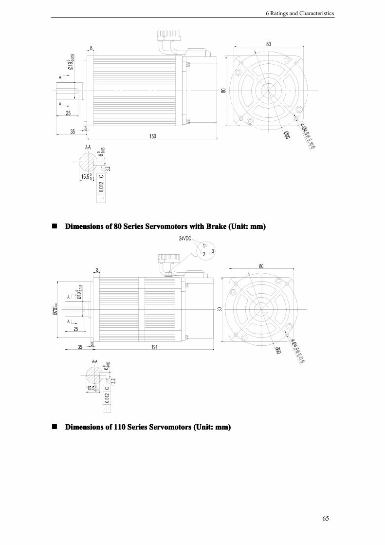
6 Ratings and Characteristics
65
���� DimensionsDimensionsDimensionsDimensions ofofofof 88880000 SeriesSeriesSeriesSeries ServomotorsServomotorsServomotorsServomotors withwithwithwith BrakeBrakeBrakeBrake (Unit:(Unit:(Unit:(Unit: mmmmmmmm))))
���� DimensionsDimensionsDimensionsDimensions ofofofof 111111110000 SeriesSeriesSeriesSeries ServomotorsServomotorsServomotorsServomotors (Unit:(Unit:(Unit:(Unit: mmmmmmmm))))

6 Ratings and Characteristics
66
���� DimensionsDimensionsDimensionsDimensions ofofofof 111111110000 SeriesSeriesSeriesSeries ServomotorsServomotorsServomotorsServomotors withwithwithwith BrakeBrakeBrakeBrake (Unit:(Unit:(Unit:(Unit: mmmmmmmm))))
���� DimensionsDimensionsDimensionsDimensions ofofofof 131313130000 SeriesSeriesSeriesSeries ServomotorsServomotorsServomotorsServomotors (Unit:(Unit:(Unit:(Unit: mmmmmmmm))))
���� DimensionsDimensionsDimensionsDimensions ofofofof 131313130000 SeriesSeriesSeriesSeries ServomotorsServomotorsServomotorsServomotors withwithwithwith BrakeBrakeBrakeBrake (Unit:(Unit:(Unit:(Unit: mmmmmmmm))))

6 Ratings and Characteristics
67
6-26-26-26-2.ServoServoServoServo DriversDriversDriversDrivers
This section describes ratings, specifications, and dimensional drawings of the servodrivers.
6-2-16-2-16-2-16-2-1.RatingsRatingsRatingsRatings
6-2-26-2-26-2-26-2-2.SpecificationsSpecificationsSpecificationsSpecifications
Servo Driver Model DS2-20P4 DS2-20P7 DS2-21P5
MotorModel MS-60ST-
M01330□□-20P4MS-80ST-M02430□□-20P7
MS-110ST-M06030□□-21P5MS-130ST-M10015□□-21P5
Speed(rpm) Rated 3000/Max 4000 Rated 1500/ Max2000
Encoder Standard: 2500 lines increamental decoderMax Motor Capacitor[kW] 0.4 0.75 1.5Continuous Output Current [Arms] 2.5 3 6
Maximum Output Current [Arms] 7.5 9 18
Power Supply Single Phase AC200~240V, 50/60HzControl Single phase full-wave rectification IPM-PWM (sinewave driven)
Condit-ions
Ambient /StorageTemperature 0~+50℃/-20~+85℃
Ambient / StorageHumidity Below 90%RH(with no condensation)
Vibration/ShockResistance 4.9m/s2 / 19.6m/s2
Configuration Base mounted
Servo Driver Model DS2-20P4 DS2-20P7 DS2-21P5
SpeedandTorqueControlModes
Performance
Speed Control Range1:4000(The lowest speed of the speedcontrol range is the point just before themotor stops under full-load condition.)
SpeedRegulation
LoadRegulation
0~100% load: 0.01% maximum (at ratedspeed)
VoltageRegulation Rated Voltage ±10%: 0% (at rated speed)
TemperatureRegulation 25 ± 25°C: ±0.1% max.(at rated speed)
Frequency Characteristics 250Hz (JL≤JM)

6 Ratings and Characteristics
68
6-2-36-2-36-2-36-2-3.ServoServoServoServo DriversDriversDriversDrivers DimensionsDimensionsDimensionsDimensions���� DS2-20P4DS2-20P4DS2-20P4DS2-20P4 andandandand DS2-20P7DS2-20P7DS2-20P7DS2-20P7 (Unit:(Unit:(Unit:(Unit: mmmmmmmm))))
Soft Start Time Setting 0~65535ms(Can be set individually foracceleration and deceleration)
Input Reference RS485
PositionControlModes
PerformanceFeedforward 0~100% (setting resolution: 1%)Positioning Completed WidthSetting
0~250 reference units (setting resolution:1 reference unit)
InputRefernce
PulseReference
Type Sign + pulse, Quadrature PulseForm Open collector(+24V level)Frequency 200kbps
Control Signal Clear Signa (/CLR)
Input /OutputSignals
Position Output None
Input Signal
Input Terminals 2 4
Signals Assignment
/S-ON、/P-CON、/P-OT、/N-OT、/ALM-RST、/PCL、/NCL、/SPD-D、/SPD-A、
/SPD-B、/C-SEL、/ZCLAMP、/CLR、/G-SEL
OutputSignal
Output Terminals 2 3
Signals Assignment/COIN、/V-CMP、/TGON、/S-RDY、/CLT、
/VLT、/BK、/WARN、/NEAR、/ALM、/Z
InternalFunctions
Dynamic Brake(DB) NoneRegeneration External regenerative resistor
Overtravel Stop Deceleration or free run to a stop at P-OTor N-OT
Electronic Gear 0.01≤B/A≤100
Protection
Program error, parameters error,overvoltage, undervoltage,overtemperature, overspeed, analog inputerror, position error overflow, output shortcirciut, current error, encoder loss,encoder error, overload, undervoltage inrun, saveing parameters error, etc.
LED Display Charge, Power, five 7-segment LEDs(built-in digital operator functions)
Communica-tions
COM1
ConnectedDevices RS232, connected to PC
ParametersBaudrate:19200, Data Bits:8, Stop Bits:1,Protocol:Modubs-RTUSlave, ModbusStation:1
Functions Debug Online
COM2
ConnectedDevices
RS485, connected to PLC, HMI or otherhost controller and PC
Parameters Configurable, Protocol:Modubs-RTUSlave, Modbus Station: Configurable
Functions
Status display, parameter setting, monitordisplay, alarm trace-back display, JOG andauto-tuning operations, speed, torquereference signal, and other drawingfunctions.

6 Ratings and Characteristics
69
���� DS2-21P5DS2-21P5DS2-21P5DS2-21P5 (Unit:(Unit:(Unit:(Unit: mmmmmmmm))))75
186
67
178
180,5+1
+2R
ST
UV
WPB
P+
POWER CHARGE
STA/ESC INC DEC ENTER
180,5

6 Ratings and Characteristics
70
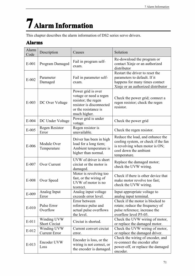
7 Alarm Information
71
7777AlarmAlarmAlarmAlarm InformationInformationInformationInformationThis chapter describes the alarm information of DS2 series servo drivers.
AlarmsAlarmsAlarmsAlarmsAlarmCode Description Causes Solution
E-001 Program Damaged Fail in program self-exam.
Re-download the program orcontact Xinje or an authorizeddistributor
E-002 ParameterDamaged
Fail in parameter self-exam.
Restart the driver to reset theparameters to default. If ithappens for many times contactXinje or an authorized distributor
E-003 DC Over Voltage
Power grid is overvotage or need a regenresistor; the regenresistor is disconnectedor the resistance ismuch higher.
Check the power grid; connect aregen resistor; check the regenresistor.
E-004 DC Under Voltage Power grid is undervotage. Check the power grid
E-005 Regen ResistorError
Regen resistor isunavailable. Check the regen resistor.
E-006 Module OverTemperature
Driver has been in highload for a long tiem;Ambient temperature ishigher than normal.
Reduce the load, and enhance thecooling system, or check if the fanis revolving when motor is ON;cool down the ambienttemperature.
E-007 Over CurrentUVW of driver is shortcirciut or the motor isdamaged.
Replace the damaged motor;check the UVW wiring.
E-008 Over Speed
Motor is revolving toofast, or the wiring ofUVW of motor is notcorrect.
Check if there is other device thatmake motor revolve too fast;check the UVW wiring.
E-009 Analog InputError
Analog input voltageexceeds error level.
Input appropriate voltage toanalog input terminal.
E-010 Pulse ErrorOverflow
Error betweenreference pulse andactual pulse overflowsthe level.
Check if the motor is blocked torotate; reduce the frequency ofpulse reference; increase theoverflow level P5-05.
E-011 Winding UVWShort Circiut Circiut is shorted. Check the UVW wiring of motor,
or replace the damaged motor.
E-012 Winding UVWCurrent Error
Current convert circiuterror.
Check the UVW wiring of motor,or replace the damaged driver.
E-013 Encoder UVWLoss
Encoder is loss, or thewiring is not correct, orthe encoder is damaged.
Check the wiring of encoder, andre-connect the encoder afterpower-off, or replace the damagedencoder.

7 Alarm Information
72
E-014 Encoder ABZLoss
Encoder is loss, or thewiring is not correct, orthe encoder is damaged.
Check the wiring of encoder, andre-connect the encoder afterpower-off, or replace the damagedencoder.
E-015 Speed FeedbackError
The wiring is notcorrect, or the encoderis interfered.
Check the wiring of encoder, orshield the encoder wire.
E-016 Overload Overload time exceedsthe level.
Reduce the time of overload, orreplace with a bigger motor
E-017 Under Voltagewhen running
DC voltage is too lowwhen running.
Restart the driver and wait for theDC to be balanced.
E-018 Erase Error DC voltage is too lowto erase the parameters. Restart the driver.
E-031 Motor Code ErrorThe code indicated inF2-00 does not suitablefor the driver.
Re-enter the motor code in F2-00.
E-032 Initialise Error System chip isdamaged.
Contact Xinje or an authorizeddistributor.

73
NoteNoteNoteNote


XinjeXinjeXinjeXinje ElectronicElectronicElectronicElectronic Co.,Co.,Co.,Co., Ltd.Ltd.Ltd.Ltd.
4th Floor Building 7,OriginalityIndustry park, LiyuanDevelopment Zone, Wuxi City,Jiangsu Province 214072
Tel: (510) 85166657
Fax: (510) 85111290