Embed Size (px)
Citation preview

FPC915
DIESEL ENGINE FIRE PUMP CONTROLLER
USER MANUAL
ZHENGZHOU SMARTGEN TECHNOLOGY CO.,LTD.

Chinese trademark
English trademark
SmartGen — make your generator smart
SmartGen Technology Co., Ltd
No. 28 Jinsuo Road
Zhengzhou City
P. R. China
Tel: 0086-371-67988888
0086-371-67981888
0086-371-67991553
0086-371-67992951
0086-371-67981000 (overseas)
Fax: 0086-371-67992952
Web: www.smartgen.com.cn
www.smartgen.cn
Email: [email protected]
All rights reserved. No part of this publication may be reproduced in any material form (including
photocopying or storing in any medium by electronic means or other) without the written permission of
the copyright holder.
SmartGen Technology reserves the right to change the contents of this document without prior notice.
Software Version
Date Version Content
2015-12-10 1.0 Original release.
2017-08-08 1.1 Change the colour of mask to red colour.

FPC915 Diesel Engine Fire Pump Controller User Manual
FPC915 Diesel Engine Fire Pump Controller Version 1.1 2017-08-08 Page 3 of 48
CONTENT
1 OVERVIEW .......................................................................................................................................... 5
2 PERFORMANCE AND CHARACTERISTICS ...................................................................................... 6
3 SPECIFICATION ................................................................................................................................... 7
4 OPERATION ......................................................................................................................................... 8
4.1 INDICATOR LIGHT .................................................................................................................. 8
4.2 PUSHBUTTONS ...................................................................................................................... 9
4.3 LCD DISPLAY ........................................................................................................................ 10
4.3.1 MAIN DISPLAY ..................................................................................................................... 10
4.3.2 USER MENU AND PARAMETERS SETTING MENU .......................................................... 11
4.4 AUTO START/STOP OPERATION ........................................................................................ 14
4.4.1 AUTOMATIC START/STOP CONDITIONS .......................................................................... 14
4.4.2 AUTOMATIC START SEQUENCE ....................................................................................... 14
4.4.3 AUTOMATIC STOP SEQUENCE ......................................................................................... 14
4.5 MANUAL START/STOP OPERATION ................................................................................... 15
5 PROTECTION .................................................................................................................................... 16
5.1 WARNINGS ............................................................................................................................ 16
5.2 SHUTDOWN ALARM ............................................................................................................. 18
5.3 INDICATION ........................................................................................................................... 19
6 CONNECTIONS ................................................................................................................................. 20
7 DEFINITION AND RANGE OF PARAMETERS ................................................................................. 23
7.1 PARAMETER CONTENTS AND RANGE (FORM 1) ............................................................ 23
7.2 PROGRAMMABLE OUTPUT ................................................................................................ 29
7.2.1 PROGRAMMABLE OUTPUT 1-5 (FORM 2) ........................................................................ 29
7.2.2 CUSTOM PERIOD OUTPUT ............................................................................................... 32
7.2.3 CUSTOM COMBINED OUTPUT .......................................................................................... 33
7.3 DEFINED CONTENTS OF CONFIGURABLE INPUT PORTS (ALL ACTIVE WHEN
CONNECT TO GRAND (B-))(FORM3) ............................................................................................. 34
7.4 SELECTION OF SENSORS (FORM4) .................................................................................. 35
7.5 CONDITIONS OF CRANK DINSCONNECT SELECTION (FORM5) ................................... 36
7.6 MAINTENANCE (FORM 6) .................................................................................................... 37
8 SENSOR SELECT .............................................................................................................................. 38
9 TYPICAL APPLICATION ..................................................................................................................... 39
10 INSTALLATION ................................................................................................................................... 40
11 CONNECTIONS OF CONTROLLER WITH J1939 ENGINE ............................................................. 41
11.1 CUMMINS ISB/ISBE .............................................................................................................. 41
11.2 CUMMINS QSL9 .................................................................................................................... 41
11.3 CUMMINS QSM11 ................................................................................................................. 41
11.4 CUMMINS QSX15-CM570 .................................................................................................... 42
11.5 CUMMINS GCS-MODBUS .................................................................................................... 42
11.6 CUMMINS QSM11 ................................................................................................................. 42

FPC915 Diesel Engine Fire Pump Controller User Manual
FPC915 Diesel Engine Fire Pump Controller Version 1.1 2017-08-08 Page 4 of 48
11.7 CUMMINS QSZ13 .................................................................................................................. 43
11.8 DETROIT DIESEL DDEC III / IV ............................................................................................ 43
11.9 DEUTZ EMR2 ........................................................................................................................ 43
11.10 JOHN DEERE ........................................................................................................................ 44
11.11 MTU MDEC ............................................................................................................................ 44
11.12 MTU ADEC(SMART MODULE) ............................................................................................. 44
11.13 MTU ADEC(SAM MODULE) .................................................................................................. 45
11.14 PERKINS ................................................................................................................................ 45
11.15 SCANIA .................................................................................................................................. 45
11.16 VOLVO EDC3 ......................................................................................................................... 45
11.17 VOLVO EDC4 ......................................................................................................................... 46
11.18 VOLVO-EMS2 ........................................................................................................................ 46
11.19 YUCHAI .................................................................................................................................. 47
11.20 WEICHAI ................................................................................................................................ 47
12 USB ..................................................................................................................................................... 47
13 FAULT FINDING ................................................................................................................................. 48

FPC915 Diesel Engine Fire Pump Controller User Manual
FPC915 Diesel Engine Fire Pump Controller Version 1.1 2017-08-08 Page 5 of 48
1 OVERVIEW
FPC915 Diesel Driven Fire Pump Controller is designed for fire pump systems which controlled by
engine. It allows automatic start/stop, data measurement, alarm protection functions. CANBUS (SAE
J1939) interface enables the controller to communicate with various engine which fitted with J1939
interface.
FPC915 Diesel Driven Fire Pump Controller fit with LCD display, optional languages interface
(including English, Chinese or other languages); simultaneously the exact parameters of pump unit
and engine are indicated by the LCD display on the front panel and the controller is reliable and easy
to use. adopt powerful 32-bit ARM microprocessor technology with precision parameters measuring,
fixed value adjustment, time setting and set value adjusting and etc. The majority of parameters can
be configured from front panel and all the parameters can be set using PC (via USB port). It can be
widely used in a number of pump control systems with compact structure, simple connections and high
reliability.

FPC915 Diesel Engine Fire Pump Controller User Manual
FPC915 Diesel Engine Fire Pump Controller Version 1.1 2017-08-08 Page 6 of 48
2 PERFORMANCE AND CHARACTERISTICS
480x272 pixel, 4.3 inches coloured TFT-LCD with backlight, multilingual interface (including English,
Chinese or other languages) which can be chosen at the site, making commissioning convenient
for factory personnel.
Improved LCD wear-resistance and scratch resistance due to hard screen acrylic.
Silicon panel and pushbuttons for better operation in high/low temperature environment.
RS485 communication port enabling remote control, remote measuring, remote communication via
ModBus protocol.
Equipped with CANBUS port and can communicate with J1939 genset. Not only can you
monitoring frequently-used data (such as water temperature, oil pressure, engine speed, fuel
consumption and so on) of ECU machine, but also control start, stop, simultaneously expand
module viaCANBUS port.
Discharge pressure curve and flow curve are user-defined.
Multiple analog sensors; sensors can switch between resistor type and current type using jumper.
More kinds of curves of temperature, oil pressure, fuel level can be used directly and users can
define the sensor curves by themselves.
Precision measure and display parameters about Engine and pump unit; e.g. engine high water
temperature, low oil pressure, over speed, high water pressure, low water pressure, over flow and
other kinds of fault indication and protection function..
All output ports are relay-out;
Parameter setting: parameters can be modified and stored in internal FLASH memory and cannot be
lost even in case of power outage; most of them can be adjusted using front panel of the controller
and all of them can be modified using PC via USB port.
Multiple crank disconnect conditions (speed sensor, oil pressure) are optional;
Widely power supply range DC(8~35)V, suitable to different starting battery voltage environment;
Event log, real-time clock, scheduled start & stop pump unit (can be set as start pump unit once a
day/week/month whether with load or not);
Accumulative total run time A and B. Users can reset it as 0 and re-accumulative the value which
make convenience to users to count the total value as their wish.
Can control engine heater, cooler and fuel pump.
With maintenance function. Actions can be set when maintenance time out;
All parameters used digital adjustment, instead of conventional analog modulation with normal
potentiometer, more reliability and stability;
Waterproof security level IP55 due to rubber seal installed between the controller enclosure and
panel fascia;
Metal fixing clips enable perfect performance in high temperature environment;
Modular design, anti-flaming ABS plastic enclosure, pluggable connection terminals and embedded
installation way; compact structure with easy mounting.

FPC915 Diesel Engine Fire Pump Controller User Manual
FPC915 Diesel Engine Fire Pump Controller Version 1.1 2017-08-08 Page 7 of 48
3 SPECIFICATION
Items Contents
Working Voltage DC8.0V to 35.0V, Continuous Power Supply.
Overall Consumption <4W(Standby mode: ≤2W)
Speed Sensor Voltage 1.0 to 24V(effective value)
Speed Sensor Frequency 10000Hz (max)
Start Relay Output 16Amp DC28V power supply
Fuel Relay Output 16Amp DC28V power supply
Active Relay Output 7Amp DC28V power supply
Voltage Free Relay Output 7Amp AC250V voltage free output
Analog Sensor 5 fixed sensor, 2 configurable sensor
Overall Dimensions 237 mm x 172 mm x 45 mm
Panel Cutout 214mm x 160mm
Working Condition Temperature: (-25~+70)°C Humidity: (20~93)%RH
Storage Condition Temperature: (-25~+70)°C
Protection Level IP55 Gasket
Weight 0.95kg

FPC915 Diesel Engine Fire Pump Controller User Manual
FPC915 Diesel Engine Fire Pump Controller Version 1.1 2017-08-08 Page 8 of 48
4 OPERATION
4.1 INDICATOR LIGHT
Note: Selected indicators description:
Warning indicator and Alarm indicator:
Alarm Type Warning Indicator Alarm Indicator
Warning Slow flashing Slow flashing
Shutdown Alarm Off Fast flashing
Running indicator: illuminated from crank successful to ETS while off during other periods.

FPC915 Diesel Engine Fire Pump Controller User Manual
FPC915 Diesel Engine Fire Pump Controller Version 1.1 2017-08-08 Page 9 of 48
4.2 PUSHBUTTONS
Icon Name Description
Stop
Stop running pump unit in Auto/Manual mode; Reset alarm in stop
mode; Lamp test (press at least 3 seconds); During stopping process,
press this button again to stop pump unit immediately.
Start 1
Press this button to start gensets via start battery in Manual mode;
after start, starting motor divorced while loose this button.
Start 2
Press this button to start gensets via control battery in Manual mode;
after start, starting motor divorced while loose this button.
Mute Alarming sound off.
Test Control magnetic valve to open in Auto mode.
Home Shortcut to return to the main screen.
Event Log Look over pipeline pressure logs.
Up/Increase 1. Screen scroll
2. Up cursor and increase value in setting menu.
Down/Decrease 1. Screen scroll
2. Down cursor and increase value in setting menu.
Left 1. Screen scroll;
2. Left move cursor in setting menu.
Right 1. Screen scroll
2. Right move cursor in setting menu.
Set/Confirm
1. Enter into “help” interface;
2. Pressing and holding for more than 3 seconds enters parameter
configuration menu.
Exit
1. Returns to the main menu;
2. In settings menu returns to the previous menu.
WARNING: Default password is 00318, user can change it in case of others change the
advanced parameters setting. Please clearly remember the password after changing. If you forget it,
please contact Smartgen services and send all information in the controller page of “ABOUT” to us.

FPC915 Diesel Engine Fire Pump Controller User Manual
FPC915 Diesel Engine Fire Pump Controller Version 1.1 2017-08-08 Page 10 of 48
4.3 LCD DISPLAY
4.3.1 Main Display
Main screen is divided into left and right separate viewing areas, use to select a viewing area;
the selected area is marked with in its upper left corner. Both viewing areas show pages; use
to scroll the pages and to scroll the screen.
★Home, including as below,
1# and 2# battery charge status, simulated header, controller modes (manual, auto, shut), engine
status and start status, accumulated run time, real-time clock.
★Engine, including as below,
Engine status, engine temperature, engine oil pressure, fuel level, battery1 voltage, battery2 voltage,
charger voltage, accumulated run time, accumulated start times.
NOTE: If connected with J1939 engine via CANBUS port, this page also includes: coolant
pressure, coolant level, fuel temperature, fuel pressure, inlet temperature, exhaust temperature, turbo
pressure, fuel consumption, total fuel consumption and so on. (Different engine with different
parameters)
★Pump Unit:
Discharge pressure, pipeline pressure, pump flow, pump head, config. sensor 1~ 2 (can be set as
temperature sensor, pressure sensor or level sensor)
Formula:Pump Head = (Discharge pressure - Static Pressure)/0.0098.
Pump flow is calculated according to relation curve of discharge pressure and flow; the relation curve
should be set by users according to the actual usage.
★Alarm:
Display all warnings, shutdown alarms.
NOTE: For ECU alarms and shutdown alarms, if the alarm information is displayed, check engine
according to it, otherwise, please check the manual of generator according to SPN alarm code.
★Event log
Records all start/stop events (shutdown alarm, trip shutdown alarm, manual/auto start or stop) and the
real time when alarm occurs.
★Others, including,
Time and Date, maintenance due time, input/output ports status.
★About, including,
Issue time of software and hardware version, product PD number.
★Status, including as below,
Engine speed, pipe network pressure, engine status.
Indicator Status
Green Normal status; No alarm
Yellow Warning alarm occurs.
Red Shutdown alarm occurs.

FPC915 Diesel Engine Fire Pump Controller User Manual
FPC915 Diesel Engine Fire Pump Controller Version 1.1 2017-08-08 Page 11 of 48
Example:
Engine Pump
Manual Mode
Noramal Running
Discharge Pressure
1.0MPa 10bar 145psi
Engine Temp
85℃ 185℉
Config Sensor1
45℃ 113℉
Oil Pressure
465kPa 4.65bar
67.4psi
Config Sensor2
465kPa 4.65bar 67.4psi
Pipe Pressure
1.0MPa 10bar 145psi Fuel Level
1500rpm 1.0MPa Normal Running
Engine Pump
Fuel Level
100%
Pipe Network Pressure
1.0MPa 10bar 145psi
Battery Voltage 1
27.6V
Pump Flow
200m³/h
Battery Voltage 2
27.6V
Pump Head
102m
Charger Voltage
28.5V
1500rpm 1.0MPa Emergency Stop
4.3.2 User Menu And Parameters Setting Menu
Press to enter into user menu;
★Parameter
After entering the correct password (factory default password is 00318), you can enter into parameter
settings interface.
★Language
Selectable Chinese, English and others.
★Commissioning
Commissioning can be chosen. Commission duration of runs can be set.
★Clear users’ accumulation
Can clear User Accumulated Run A, User Accumulated Run B, Engine Accumulated Run time and
Accumulated Start times.
Parameter setting including as following,
★Timer settings
★Engine settings
★Analog sensor settings (Engine temperature, engine oil pressure, fuel level, config. 1~2, pipe
network pressure)
★Input port settings

FPC915 Diesel Engine Fire Pump Controller User Manual
FPC915 Diesel Engine Fire Pump Controller Version 1.1 2017-08-08 Page 12 of 48
★Output port settings
★Expansion output module
★Module settings
★Scheduling and maintenance settings
Example
Return >Start Delay
>Stop Delay
>Preheat Delay
>Cranking Time
> Crank Rest Time
> Safety On Time
> Start Idle Time
> Warming Up Time
> Cooling Time
> Stop Idle Time
> ETS Hold Time
Form1: Use to scroll settings,
to enter settings (form2), to exit
settings menu.
Timers >
Engine
Temp. Sensor
OP Sensor
Level Sensor
Config Sensor 1 Config
Sensor 2
Pipe Pressure
Discharge Press
Digit Inputs
Return > Start Delay Form 2: Use to scroll settings
(form 3), to enter settings (form 4),
to return to previous menu. (form 1).
Timers > >Stop Delay
>Preheat Delay
>Cranking Time
>Crank Rest Time
>Safety On Time
>Start Idle Time
>Warming Up Time
>Cooling Time
>Stop Idle Time
> ETS Hold Time
Engine
Temp. Sensor
OP Sensor
Level Sensor
Config Sensor 1 Config
Sensor 2
Pipe Pressure
Discharge Press
Digit Inputs
Return >Start Delay
>Stop Delay
>Preheat Delay
Form 3: Use to scroll settings,
to enter settings (form4), to return
to previous menu. (form 1).
Timers >
Engine
Temp. Sensor
OP Sensor
Level Sensor
Config Sensor 1 Config
Sensor 2
Pipe Pressure
Discharge Press
Digit Inputs
>Cranking Time
>Crank Rest Time
>Safety On Time
>Start Idle Time
>Warming Up Time
>Cooling Time
>Stop Idle Time
>ETS Hold Time

FPC915 Diesel Engine Fire Pump Controller User Manual
FPC915 Diesel Engine Fire Pump Controller Version 1.1 2017-08-08 Page 13 of 48
> Start Delay
> Stop Delay
> Preheat Delay
Form 4:Press to enter settings (form
5), to return to previous menu. (form
6).
00008
>Cranking Time
>Crank Rest Time
> Safety On Time
> Start Idle Time
> Warming Up Time
> Cooling Time
> Stop Idle Time
> ETS Hold Time
> Start Delay
> Stop Delay
> Preheat Delay
00008 Form5: Press to change cursor
position, are used for
changing cursor value, Confirm
setting (form 4), exit setting (form 4).
>Cranking Time
>Crank Rest Time
> Safety On Time
> Start Idle Time
> Warming Up Time
> Cooling Time
> Stop Idle Time
> ETS Hold Time
> Start Delay
> Stop Delay
> Preheat Delay
00008
Form 6: are used for
changing the setting contents.
Confirm setting (form 4), to return to
previous menu. (form 1).
> Cranking Time
> Crank Rest Time
> Safety On Time
> Start Idle Time
> Warming Up Time
> Cooling Time
> Stop Idle Time
> ETS Hold Time
> Wait Stop Time
NOTE: Pressing can exit setting directly during setting.

FPC915 Diesel Engine Fire Pump Controller User Manual
FPC915 Diesel Engine Fire Pump Controller Version 1.1 2017-08-08 Page 14 of 48
4.4 AUTO START/STOP OPERATION
When auto mode is active, auto mode will be displayed on LCD to confirm the operation.
4.4.1 Automatic Start/Stop Conditions
1) When Pipe Pressure is lower than set value, start automatically; when pipe pressure arrives set
value, stop automatically;
2) When Remote Auto Start (always close) open, start automatically (only transfer to OFF mode can
stop);
3) When Deluge Valve Start (always close) open, start automatically (only transfer to OFF mode can
stop);
4) When Remote Manual Start (always open) close, start automatically (only transfer to OFF mode
can stop);
5) Scheduled Start; Over Time Start; stop after operation for the set time.
6) Test Start, start after pressed the TEST button, stop after the operation for the set time, or press
the STOP button, or stop in OFF mode.
Note: After Auto Start, a, b, c, d only can overspeed alarm stop, the others only can overspeed
alarm but not stop; e, f other alarm stop can occur when in operation which make Pipe Pressure lower
to start by connecting to test magnetic valve.
4.4.2 Automatic Start Sequence
7) When satisified the auto start conditions, “Start Delay” timer is initiated.
8) When start delay is over, preheat relay energizes (if configured), “preheat delay XX s” information
will be displayed on LCD;
9) After the above delay, the Fuel Relay is energized, and then one second later, the Start Relay is
engaged. The engine is cranked for a pre-set time. If the pump unit fails to fire during this cranking
attempt then the fuel relay and start relay are disengaged for the pre-set rest period; “crank rest
time” begins and wait for the next crank attempt.
10) Should this start sequence continue beyond the set number of attempts, the start sequence will be
terminated, the Fail to Start fault will be displayed on LCD.
11) In case of successful crank attempt, the “Safety On” timer is activated, allowing Low Oil Pressure,
High Temperature, Under speed and Charge Alternator Failure inputs to stabilize without
triggering the fault. As soon as this delay is over, “start idle” delay is initiated (if configured).
12) During “start idle” delay, under speed alarm is inhibited. When this delay is over, “warming up”
delay is initiated (if configured).
13) After the “warming up” delay, pump unit will enter into Normal Running status.
4.4.3 Automatic Stop Sequence
1) When satisified the stop conditions, “Stop Delay” timer is initiated (if alarm stop, please go to step
4).
2) Once this “stop delay” has expired, the “Cooling Delay” is then initiated. Then the “Stop Idle” delay
is initiated.
3) During “Stop Idle” Delay (if configured), idle relay is energized.
4) “ETS Solenoid Hold” begins, ETS relay is energized while fuel relay is de-energized.
5) "Fail to Stop Delay" begins, complete stop is detected automatically.
6) Pump unit is placed into its “After stop time” after its complete stop. Otherwise, fail to stop alarm is
initiated and the corresponding alarm information is displayed on LCD (If pump unit stopped
successfully after “Failed to Stop” alarm, it will enter “After stop time” and remove alarm).
7) Pump unit is placed into its standby mode after its “After stop time”.

FPC915 Diesel Engine Fire Pump Controller User Manual
FPC915 Diesel Engine Fire Pump Controller Version 1.1 2017-08-08 Page 15 of 48
4.5 MANUAL START/STOP OPERATION
When manual mode is active, manual mode will be displayed on LCD to confirm the operation.
1) Manual Start: Press Start1 or Start 2 button to start the unit. Loose the button
after start, and unit accelerates to high-speed running automatically. When press Start1, the unit is
started via battery1; when press Start2, the unit is started via battery2.
With high temperature, low oil pressure and over speed during pump unit running, controller can
protect it to stop quickly (Please refer to No.2~7 of Auto start operation for detail procedures) Start
time is only 1 time. If start failed, fail alarm will be initiated.
2) MANUAL STOP: Press can stop the running pump unit. (Please refer to No.2~7 of Auto
stop operation for detail procedures).
If auto start condition is satisfied before shutdown, then it cannot shutdown. If shutdown is still
needed, you can transfer the controller into OFF mode.

FPC915 Diesel Engine Fire Pump Controller User Manual
FPC915 Diesel Engine Fire Pump Controller Version 1.1 2017-08-08 Page 16 of 48
5 PROTECTION
5.1 WARNINGS
Warnings are not shutdown alarms and do not affect the operation of the genset. Warning does not
lead to shutdown, and when warning condition is no longer present, warning alarm will be cleared
automatically. Warning types are as follows:
No. Type Description
1 Over Speed When the controller detects that the engine speed has exceeded the
pre-set value, it will initiate a warning alarm.
2 Under Speed When the controller detects that the engine speed has fallen below the
pre-set value, it will initiate a warning alarm.
3 Loss of Speed Signal When the controller detects that the engine speed is 0 and the action
select “Warn”, it will initiate a warning alarm.
4 Fail To Stop After “fail to stop” delay, if unit is not stop completely, it will initiate a
warning alarm.
5 Charge Alt Fail When the controller detects that charger voltage has fallen below the
pre-set value, it will initiate a warning alarm.
6 Battery 1 Over Voltage When the controller detects that battery 1 voltage has exceeded the
pre-set value, it will initiate a warning alarm.
7 Battery 1 Under
Voltage
When the controller detects that battery 1 voltage has fallen below the
pre-set value, it will initiate a warning alarm.
8 Maintenance Due When maintenance countdown time is 0 and the action select “Warn”,
it will initiate a warning alarm.
9 ECU Warn If an error message is received from ECU via J1939, it will initiate a
warning alarm.
10 Temperature Sensor
Open Circuit
When the controller detects that the temperature sensor is open circuit
and the action select “Warn”, it will initiate a warning alarm.
11 High Temperature When the controller detects that engine temperature has exceeded
the pre-set value, it will initiate a warning alarm.
12 Low Temperature When the controller detects that engine temperature has fallen below
the pre-set value, it will initiate a warning alarm.
13 Oil Pressure Open
Circuit
When the controller detects that the oil pressure sensor is open circuit
and the action select “Warn”, it will initiate a warning alarm.
14 Low Oil Pressure When the controller detects that the oil pressure has fallen below the
pre-set value, it will initiate a warning alarm.
15 Level Sensor Open When the controller detects that the level sensor is open circuit and
the action select “Warn”, it will initiate a warning alarm.
16 Low Fuel Level When the controller detects that the fuel level has fallen below the
pre-set value, it will initiate a warning alarm.
17 Flexible Sensor 1~2
Open
When the controller detects that the sensor is open circuit and the
action select “Warn”, it will initiate a warning alarm.
18 Flexible Sensor 1~2
High
When the controller detects the sensor value is higher than the max.
set value, it will initiate a warning alarm.
19 Flexible Sensor 1~2
Low
When the controller detects the sensor value is lower than the min. set
value, it will initiate a warning alarm.

FPC915 Diesel Engine Fire Pump Controller User Manual
FPC915 Diesel Engine Fire Pump Controller Version 1.1 2017-08-08 Page 17 of 48
No. Type Description
20 Digital Input 1~8 Warn When the action of digital input port select “Warn” and active, it will
initiate a warning alarm.
21 Battery 2 Over Voltage When the controller detects that battery 2 voltage has exceeded the
pre-set value, it will initiate a warning alarm.
22 Battery 2 Under
Voltage
When the controller detects that battery 2 voltage has fallen below the
pre-set value, it will initiate a warning alarm.
23 Pipe Pressure Sensor
Open
When the controller detects that the pipe pressure sensor is open
circuit and the action select “Warn”, it will initiate a warning alarm.
24 Pipe Pressure Sensor
High
When the controller detects the sensor value is higher than the max.
set value, it will initiate a warning alarm.
25 Pipe Pressure Sensor
Low
When the controller detects the sensor value is lower than the min. set
value, it will initiate a warning alarm.
26 Discharge Pressure
Sensor Open
When the controller detects that the discharge pressure sensor is
open circuit and the action select “Warn”, it will initiate a warning
alarm.
27 Discharge Pressure
Sensor High
When the controller detects the sensor value is higher than the max.
set value, it will initiate a warning alarm.
28 Discharge Pressure
Sensor Low
When the controller detects the sensor value is lower than the min. set
value, it will initiate a warning alarm.
29 Over Flow Warn When the controller detects the flow value is higher than the max. set
value, it will initiate a warning alarm.
30 End Of The Mandate When the mandate time has expired and the action select “Warn”, it
will initiate a warning alarm.
31 Output-Mod Com Fail When the expansion module which is circumscribed by CAN port
communication fails, it will initiate a warning alarm.
32 Charger1 AC Fail When the charger1 detects utility failure, it will initiate a warning alarm.
33 Charger2 AC Fail When the charger2 detects utility failure, it will initiate a warning alarm.
34 Charger1 Com. Fail When the controller cannot communicate with charger1 normally, it will
initiate a warning alarm.
35 Charger2 Com. Fail When the controller cannot communicate with charger2 normally, it will
initiate a warning alarm.
36 Charger1 Charging
Fail
When the charger1 cannot charge the battery normally, it will initiate a
warning alarm.
37 Charger2 Charging
Fail
When the charger2 cannot charge the battery normally, it will initiate a
warning alarm.
38 Low Suction When low suction is active, it will initiate a warning alarm.
39 Water Reservoir Low When water reservoir low is active, it will initiate a warning alarm.
40 Water Reservoir
Empty When water reservoir empty is active, it will initiate a warning alarm.
FPC915 Diesel Engine Fire Pump Controller User Manual
FPC915 Diesel Engine Fire Pump Controller Version 1.1 2017-08-08 Page 18 of 48
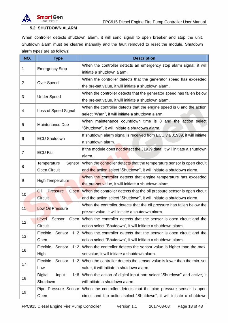
5.2 SHUTDOWN ALARM
When controller detects shutdown alarm, it will send signal to open breaker and stop the unit.
Shutdown alarm must be cleared manually and the fault removed to reset the module. Shutdown
alarm types are as follows:
NO. Type Description
1 Emergency Stop When the controller detects an emergency stop alarm signal, it will
initiate a shutdown alarm.
2 Over Speed When the controller detects that the generator speed has exceeded
the pre-set value, it will initiate a shutdown alarm.
3 Under Speed When the controller detects that the generator speed has fallen below
the pre-set value, it will initiate a shutdown alarm.
4 Loss of Speed Signal When the controller detects that the engine speed is 0 and the action
select “Warn”, it will initiate a shutdown alarm.
5 Maintenance Due When maintenance countdown time is 0 and the action select
“Shutdown”, it will initiate a shutdown alarm.
6 ECU Shutdown If shutdown alarm signal is received from ECU via J1939, it will initiate
a shutdown alarm.
7 ECU Fail If the module does not detect the J1939 data, it will initiate a shutdown
alarm.
8 Temperature Sensor
Open Circuit
When the controller detects that the temperature sensor is open circuit
and the action select “Shutdown”, it will initiate a shutdown alarm.
9 High Temperature When the controller detects that engine temperature has exceeded
the pre-set value, it will initiate a shutdown alarm.
10 Oil Pressure Open
Circuit
When the controller detects that the oil pressure sensor is open circuit
and the action select “Shutdown”, it will initiate a shutdown alarm.
11 Low Oil Pressure When the controller detects that the oil pressure has fallen below the
pre-set value, it will initiate a shutdown alarm.
12 Level Sensor Open
Circuit
When the controller detects that the sensor is open circuit and the
action select “Shutdown”, it will initiate a shutdown alarm.
13 Flexible Sensor 1~2
Open
When the controller detects that the sensor is open circuit and the
action select “Shutdown”, it will initiate a shutdown alarm.
16 Flexible Sensor 1~2
High
When the controller detects the sensor value is higher than the max.
set value, it will initiate a shutdown alarm.
17 Flexible Sensor 1~2
Low
When the controller detects the sensor value is lower than the min. set
value, it will initiate a shutdown alarm.
18 Digital Input 1~8
Shutdown
When the action of digital input port select “Shutdown” and active, it
will initiate a shutdown alarm.
19 Pipe Pressure Sensor
Open
When the controller detects that the pipe pressure sensor is open
circuit and the action select “Shutdown”, it will initiate a shutdown

FPC915 Diesel Engine Fire Pump Controller User Manual
FPC915 Diesel Engine Fire Pump Controller Version 1.1 2017-08-08 Page 19 of 48
NO. Type Description
alarm.
20 Pipe Pressure Sensor
High
When the controller detects the sensor value is higher than the max.
set value, it will initiate a shutdown alarm.
21 Pipe Pressure Sensor
Low
When the controller detects the sensor value is lower than the min. set
value, it will initiate a shutdown alarm.
22 Discharge Pressure
Sensor Open
When the controller detects that the discharge pressure sensor is
open circuit and the action select “Shutdown”, it will initiate a shutdown
alarm.
23 Discharge Pressure
Sensor High
When the controller detects the sensor value is higher than the max.
set value, it will initiate a shutdown alarm.
24 Discharge Pressure
Sensor Low
When the controller detects the sensor value is lower than the min. set
value, it will initiate a shutdown alarm.
25 Over Flow Shutdown When the controller detects the flow value is higher than the max. set
value, it will initiate a shutdown alarm.
26 Output-Mod Com Fail When the controller’s communication with expansion module fails, it
will initiate a warning alarm.
5.3 INDICATION
On initiation of the indication alarm the controller does not perform any action, and the alarm
information will be displayed on Alarm page.
Indication alarm types are as follows:
No. Type Description
1 Maintain Over Time When maintenance countdown time is 0 and the action select
“Indication”, it will initiate a indication alarm.
2 Digital Input 1~8 When the action of digital input port select “Indication” and active, it
will initiate a indication alarm.

FPC915 Diesel Engine Fire Pump Controller User Manual
FPC915 Diesel Engine Fire Pump Controller Version 1.1 2017-08-08 Page 20 of 48
6 CONNECTIONS
FPC915 controller back panel is shown below:
Description of terminal connections:
Pin Function Cable Size Description
1 B- 2.5mm2 Connected with negative of starter battery.
2 B+ 2.5mm2
Connected with positive of starter battery. If wire length is
over 30m, better to double wires in parallel. Max. 20A fuse is
recommended.
3 Emergency Stop 2.5mm2 Connected with B+ power supply via emergency stop button.
4 Fuel Relay Output 1.5mm2 B+ power is supplied by terminal 3, rated 16A
5 Start Relay1 Output 1.5mm2
B+ power is supplied by terminal 3,
rated 16A
Control the starter via
battery1.
6 Start Relay2 Output 1.5mm2
B+ power is supplied by terminal 3,
rated 16A
Control the starter via
battery1.
7 SV Output 1.5mm2 B+ power is supplied by terminal 2, rated 7A
8 ETS Output 1.5mm2 B+ power is supplied by terminal 2, rated 7A
9 Aux. Output 1 1.5mm2
B+ power is supplied by terminal 2,
rated 7A Details see form 2
10 Aux. Output 2 1.5mm2
B+ power is supplied by terminal 2,
rated 7A

FPC915 Diesel Engine Fire Pump Controller User Manual
FPC915 Diesel Engine Fire Pump Controller Version 1.1 2017-08-08 Page 21 of 48
Pin Function Cable Size Description
11 Aux. Output 3 1.5mm2
B+ power is supplied by terminal 2,
rated 7A
12 Charger(D+) 1.0mm2
Connected with charger starter’s D+ (WL) terminals. Being
hang up If there is no this terminal.
13 Aux. Input 1 1.0mm2 Ground connected is active (B-)
Details see form 3 14 Aux. Input 2 1.0mm
2 Ground connected is active (B-)
15 Aux. Input 3 1.0mm2 Ground connected is active (B-)
16 Aux. Input 4 1.0mm2 Ground connected is active (B-)
17 Oil Pressure Low 1.0mm2 Ground connected is active (B-)
18 Water Temp. High 1.0mm2 Ground connected is active (B
19 Remote Auto Start 1.0mm2 Ground connected is inactive (B-), but hanging.
20 Remote Manu Start 1.0mm2 Ground connected is active (B-)
21 Deluge Valve Start 1.0mm2 Ground connected is inactive (B-), but hanging.
22 Common GND(B-) 1.0mm2 (B-) has already connected innerly.
23 Engine Run 1.0mm2
Connection to positive (B+) is active. 24 Over Speed 1.0mm
2
25 Magnetic Pickup
GND / (B-) has already connected with ground innerly.
26 Engine Magnetic
Pickup 2 0.5mm
2
Connected with Engine Speed Sensor, shielding line is
recommended. (B-) has already connected with speed sensor
innerly. 27 Engine Magnetic
Pickup 1
28 Aux. Input 5 1.0mm2 Ground connected is active (B-)
29
Engine Trouble 1.5mm2
Normally close output, rated 7A Output when overspeed shutdown, failed to start, oil pressure low and water temperature high shutdown alarms
30 Public points of relay
31 Normally open output, rated 7A
32
Engine Run 1.5mm2
Normally close output, rated 7A Output when genset
runs 33 Public points of relay
34 Normally open output, rated 7A
35
Non Auto Alarm 1.5mm2
Normally close output, rated 7A Output when controller
is in manual/OFF mode 36 Public points of relay
37 Normally open output, rated 7A
38
Controller Trouble 1.5mm2
Normally close output, rated 7A Output when common
alarms 39 Public points of relay
40 Normally open output, rated 7A
41 Aux. Input 6 1.0mm2 Ground connected is active (B-)
42 Aux. Input 7 1.0mm2 Ground connected is active (B-)

FPC915 Diesel Engine Fire Pump Controller User Manual
FPC915 Diesel Engine Fire Pump Controller Version 1.1 2017-08-08 Page 22 of 48
Pin Function Cable Size Description
43 Aux. Input8 1.0mm2 Ground connected is active (B-)
44 Common GND(B-) 1.0mm2 (B-) has already connected innerly.
45 ECU CAN L 0.5mm2 Impedance-120Ω shielding wire is recommended, its
single-end earthed. 120Ω matched resistance has already
connected internally.
46 ECU CAN H 0.5mm2
47 ECU CAN COM /
48 Oil pressure sensor 1.0mm2 Connected to oil pressure sensor
49 Temperature sensor 1.0mm2 Connected to temperature sensor
50 Fuel level sensor 1.0mm2 Connected to fuel level sensor
51 Sensor COM 1 1.0mm2 Public terminal of sensor, (B-) has already connected.
52 Discharge Pressure
Sensor 1.0mm
2
Pump sensor
53 Pipe Pressure
Sensor 1.0mm
2
54 Aux. sensor 1 1.0mm2 Spare sensor of pump unit
Details see form 4 55 Sensor COM 2 1.0mm2
Public terminal of sensor, (B-) has
already connected.
56 Aux. sensor 2 1.0mm2 Spare sensor of pump unit
57 Auto Position 1.0mm2 Connected to panel electric lock, chose the work mode for
controller. 58 Hand Position 1.0mm2
59 Lockout Input 1.0mm2
The genset won’t auto start if the genset didn’t start when
lockout input is active.
60 Common (B-) 1.0mm2 (B-) has already connected innerly.
61 RS485 / Impedance-120Ω shielding wire is recommended, its
single-end earthed. 62 RS485+ 0.5mm
2
63 RS485- 0.5mm2
NOTE: USB ports in controller rear panel are programmable parameter ports, user can directly
configure controller via PC in stop mode.

FPC915 Diesel Engine Fire Pump Controller User Manual
FPC915 Diesel Engine Fire Pump Controller Version 1.1 2017-08-08 Page 23 of 48
7 DEFINITION AND RANGE OF PARAMETERS
7.1 PARAMETER CONTENTS AND RANGE (FORM 1)
No. Items Parameter Default Description
Timer Setting
1 Start Delay (0-3600)s 1 Time from remote start signal is active to start the
pump unit.
2 Return Delay (0-3600)s 1 Time from remote stop signal is deactivated to
stop the pump unit.
3 Preheat Delay (0-3600)s 0 Time of pre-powering heat plug before starter is
powered up.
4 Cranking Time (3-60)s 8 Time of starter power up
5 Crank Rest Time (3-60)s 10 The waiting time before second power up when
engine start fail.
6 Safety On Delay (0-3600)s 10
Alarms for low oil pressure, high temperature,
under speed, under frequency/voltage, charge
fail are inactive.
7 Start Idle Time (0-3600)s 0 Idle running time of the pump unit when starting.
8 Warming Up Time (0-3600)s 10 Warming time between the pump unit take load
and high speed running.
9 Cooling Time (0-3600)s 0 Radiating time before stop the pump unit, after it
unloads.
10 Stop Idle Time (0-3600)s 0 Idle running time when pump unit stop.
11 ETS Hold Hold (0-3600)s 20 Stop electromagnet’s power on time when pump
unit is stopping.
12 Fail to Stop Delay (0-3600)s 0
Time between ending of pump unit idle delay and
stopped when “ETS time” is set as 0;
Time between ending of ETS hold delay and
stopped when “ETS Hold output time” is not 0.
13 After Stop Time (0-3600)s 0 Time between pump unit stopped and standby.
Engine Setting
1 Engine Type (0-39) 0
Default: Conventional genset (not J1939)
When connected to J1939 engine, choose the
corresponding type.
2 Flywheel Teeth (10-300) 118
Tooth number of the engine, for judging of starter
separation conditions and inspecting of engine
speed. See the following Installation Instruction.
3 Rated Speed (0-6000)r/min 1500 Offer standard to judge over/under/loading
speed.
4 Loss of Speed
Signal (0-3600)s 5
Time from detecting speed is 0 to confirm the
action.
5 Loss of Speed
Action (0-1) 0 0:Warn; 1:Shutdown
6 Over Speed
Shutdown (0-200)% 114%
Setting value is percentage of rated speed and
delay value can be set.

FPC915 Diesel Engine Fire Pump Controller User Manual
FPC915 Diesel Engine Fire Pump Controller Version 1.1 2017-08-08 Page 24 of 48
No. Items Parameter Default Description
7 Under Speed
Shutdown (0-200)% 80%
8 Over Speed Warn (0-200)% 110% Setting value is percentage of rated speed. Delay
value and return value can be set. 9 Under Speed
Warn (0-200)% 86%
10 Battery 1 Rated
Voltage (0-60.0)V 24.0
Standard for detecting over/under voltage of
battery.
11 Battery 1 Over
Volts (0-200)% 120%
Setting value is percentage of rated voltage of
battery. Delay value & return value can be set. 12
Battery 1 Under
Volts (0-200)% 85%
13 Battery 2 Rated
Voltage (0-60.0)V 24.0
Standard for detecting over/under voltage of
battery.
14 Battery 2 Over
Volts (0-200)% 120%
Setting value is percentage of rated voltage of
battery. Delay value & return value can be set. 15
Battery 2 Under
Volts (0-200)% 85%
16 Charge Alt Fail (0-60.0)V 8.0 In normal running, when charger D+(WL) voltage
under this value, charge failure alarms.
17 Start Attempts (1-10) times 3
Max. Crank times of crank attempts. When reach
this number, controller will send start failure
signal.
18 Crank Disconnect (0-6) 2
See form 5.
There are 3 conditions of disconnecting starter
with engine. Each condition can be used alone
and simultaneously to separating the start motor
and genset as soon as possible.
19 Disconnect
Engine Speed (0-1000)% 24%
Setting value is percentage of rated speed.
When engine speed is higher than the set value,
starter will be disconnected. See the following
Installation Instruction.
20 Disconnect OP (0-1000)kPa 200
When generator oil pressure is higher than the
set value, starter will be disconnected. See the
following Installation Instruction.
Module Setting
1 Module Address (1-254) 1 Controller’s address during remote sensing.
2 Stop Bits (0-1) 0 0: 2 stop bits; 1: 1 stop bit
3 Language (0-2) 0 0: Simplified Chinese 1: English
2: Others
4 Password (0-65535) 00318 For entering advanced parameters setting.
5 Time and Date User set
Scheduling And Maintenance Setting
1 Scheduled Run (0-1) 0 0: Disable;1: Enable
2 Scheduled Not (0-1) 0 0: Disable;1: Enable

FPC915 Diesel Engine Fire Pump Controller User Manual
FPC915 Diesel Engine Fire Pump Controller Version 1.1 2017-08-08 Page 25 of 48
No. Items Parameter Default Description
Run
3 Maintenance 1 (0-1) 0 0: Disable;1: Enable
Users can set maintenance time, maintenance
due action, prealarm A, prealarm B, timer mode
and reset maintenance alarm. If maintenance
due alarm occurs, users can reset maintenance
alarm to remove it.
4 Maintenance 2 (0-1) 0
5 Maintenance 3 (0-1) 0
6 Maintenance 4 (0-1) 0
7 Maintenance 5 (0-1) 0
Analog Sensors Setting
Temperature Sensor
1 Curve Type (0-15) 7 SGX. See form 5.
2 Open Action (0-2) 0 0: Warn; 1: Shutdown; 2: No action
3 High Temp.
Shutdown (0~300)ºC 98
Shutdown when external sensor temperature is
higher than this value. Detecting only after safety
delay is over. The delay value can be set.
4 High Temp. Warn (0~300)ºC 95
Warn when external sensor temperature is
higher than this value. Detecting only after safety
delay is over. The delay value and return value
can be set.
5 Low Temp. Warn (0-1) 0 0: Disable;1: Enable
6 Custom Curve Users should set the corresponding curve when
select resistor curve type or current curve type.
Oil Pressure Sensor
1 Curve Type (0-15) 7 SGX. See form 5.
2 Open Action (0-2) 0 0: Warn; 1: Shutdown; 2: No action
3 Low OP Shutdown (0-1000)kPa 103
Shutdown when external oil pressure is lower
than this value. Detecting only after safety delay
is over. The delay value can be set.
4 Low OP Warn (0-1000)kPa 124
Warn when external oil pressure is higher than
this value. Detecting only after safety delay is
over. The delay value and return value can be
set.
5 Custom Curve Users should set the corresponding curve when
select resistor curve type or current curve type.
Liquid Level Sensor
1 Curve Type (0-15) 4 SGH. See form 5.
2 Open Action (0-2) 0 0:Warn; 1:Shutdown; 2:No action
3 Low Level Warn (0-1000)% 10
Warn when external level is lower than this value.
It is detecting all the time. The delay value and
return value can be set.
4 Custom Curve Users should set the corresponding curve when
select resistor curve type or current curve type.
Flexible Sensor 1~2
1 Flexible Sensor
Setting (0-1) 0
0: Disable ; 1: Enable (can be set as
temperature/oil pressure/liquid lever sensor)

FPC915 Diesel Engine Fire Pump Controller User Manual
FPC915 Diesel Engine Fire Pump Controller Version 1.1 2017-08-08 Page 26 of 48
No. Items Parameter Default Description
2 Curve Type Depends on sensor type.
3 Open Action (0-2) 0 0:Warn; 1:Shutdown; 2:No action
4 High Shutdown (0-9000) 100
Shutdown when external sensor value is higher
than this value. The delay value and “warn
enable” can be set.
5 Low Shutdown (0-9000) 10
Shutdown when external sensor value is lower
than this value. The delay value and “warn
enable” can be set.
6 High Warn (0-9000) 90
Warn when external sensor value is higher than
this value. The delay value, “warn enable” and
return value can be set.
7 Low Warn (0-9000) 20
Warn when external sensor value is lower than
this value. The delay value, “warn enable” and
return value can be set.
8 Custom Curve Users should set the corresponding curve when
select resistor curve type or current curve type.
Pipe Pressure Sensor
1 Curve Type (0-15) 2
2 Open Action (0-2) 1 0:Warn; 1:Shutdown; 2:No action
3 Over Stop (0-9000) 1000
Shutdown when external sensor value is over
this value. The delay value and “warn enable”
can be set.
4 Under Start (0-9000) 600
Shutdown when external sensor value is under
this value. The delay value and “warn enable”
can be set.
5 Over Warn (0-9000) 1200
Warn when external sensor value is over this
value. The delay value, “warn enable” and return
value can be set.
6 Under Warn (0-9000) 200
Warn when external sensor value is under this
value. The delay value, “warn enable” and return
value can be set.
7 Custom Curve Users should set the corresponding curve when
select resistor curve type or current curve type.
Discharge Pressure Sensor
1 Curve Type (0-15) 2
2 Open Action (0-2) 1 0:Warn; 1:Shutdown; 2:No action
3 High Shutdown (0-9000)% 80
Shutdown when external sensor value is higher
than this value. The delay value and “warn
enable” can be set.
4 Low Shutdown (0-9000)% 50
Shutdown when external sensor value is lower
than this value. The delay value and “warn
enable” can be set.
5 High Warn (0-9000)% 110 Warn when external sensor value is higher than
this value. The delay value, “warn enable” and
FPC915 Diesel Engine Fire Pump Controller User Manual
FPC915 Diesel Engine Fire Pump Controller Version 1.1 2017-08-08 Page 27 of 48
No. Items Parameter Default Description
return value can be set.
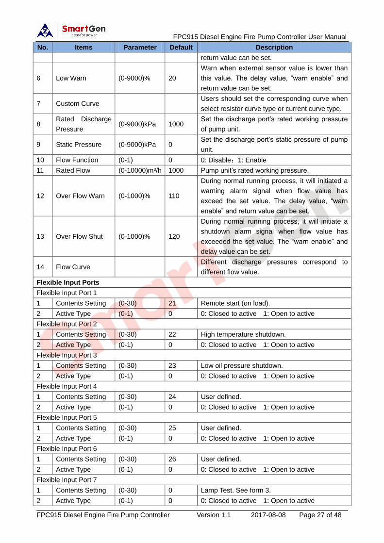
6 Low Warn (0-9000)% 20
Warn when external sensor value is lower than
this value. The delay value, “warn enable” and
return value can be set.
7 Custom Curve Users should set the corresponding curve when
select resistor curve type or current curve type.
8 Rated Discharge
Pressure (0-9000)kPa 1000
Set the discharge port’s rated working pressure
of pump unit.
9 Static Pressure (0-9000)kPa 0 Set the discharge port’s static pressure of pump
unit.
10 Flow Function (0-1) 0 0: Disable;1: Enable
11 Rated Flow (0-10000)m³/h 1000 Pump unit’s rated working pressure.
12 Over Flow Warn (0-1000)% 110
During normal running process, it will initiated a
warning alarm signal when flow value has
exceed the set value. The delay value, “warn
enable” and return value can be set.
13 Over Flow Shut (0-1000)% 120
During normal running process, it will initiate a
shutdown alarm signal when flow value has
exceeded the set value. The “warn enable” and
delay value can be set.
14 Flow Curve Different discharge pressures correspond to
different flow value.
Flexible Input Ports
Flexible Input Port 1
1 Contents Setting (0-30) 21 Remote start (on load).
2 Active Type (0-1) 0 0: Closed to active 1: Open to active
Flexible Input Port 2
1 Contents Setting (0-30) 22 High temperature shutdown.
2 Active Type (0-1) 0 0: Closed to active 1: Open to active
Flexible Input Port 3
1 Contents Setting (0-30) 23 Low oil pressure shutdown.
2 Active Type (0-1) 0 0: Closed to active 1: Open to active
Flexible Input Port 4
1 Contents Setting (0-30) 24 User defined.
2 Active Type (0-1) 0 0: Closed to active 1: Open to active
Flexible Input Port 5
1 Contents Setting (0-30) 25 User defined.
2 Active Type (0-1) 0 0: Closed to active 1: Open to active
Flexible Input Port 6
1 Contents Setting (0-30) 26 User defined.
2 Active Type (0-1) 0 0: Closed to active 1: Open to active
Flexible Input Port 7
1 Contents Setting (0-30) 0 Lamp Test. See form 3.
2 Active Type (0-1) 0 0: Closed to active 1: Open to active

FPC915 Diesel Engine Fire Pump Controller User Manual
FPC915 Diesel Engine Fire Pump Controller Version 1.1 2017-08-08 Page 28 of 48
No. Items Parameter Default Description
3 Arming (0-3) 2 0: From safety on 1: From starting
2: Always 3:Never
4 Active Actions (0-4) 2 0: Warn; 1: Shutdown; 2: Indication
5 Active Delay (0-20.0)s 2.0 Time from detecting active to confirm.
6 Description User defined.
Flexible Input Port 8
1 Contents Setting (0-30) 0 User defined. See form 3.
2 Active Type (0-1) 0 0: Closed to active 1: Open to active
3 Arming (0-3) 0 0: From safety on 1: From starting
2: Always 3:Never
4 Active Actions (0-4) 0 0: Warn; 1: Shutdown; 2: Indication
5 Active Delay (0-20.0)s 2.0 Time from detecting active to confirm.
6 Description User defined.
Flexible Output Ports
Flexible Output Port 1
1 Contents Setting (0-239) 1 User defined period output (default output is in
preheating) See form 4.
2 Active Type (0-1) 0 0:Normally open; 1:Normally close
Flexible Output Port 2
1 Contents Setting (0-239) 35 Idle speed control. See form 4.
2 Active Type (0-1) 0 0:Normally open; 1:Normally close
Flexible Output Port 3
1 Contents Setting (0-239) 29 Reserved. See form 4.
2 Active Type (0-1) 0 0:Normally open; 1:Normally close

FPC915 Diesel Engine Fire Pump Controller User Manual
FPC915 Diesel Engine Fire Pump Controller Version 1.1 2017-08-08 Page 29 of 48
7.2 PROGRAMMABLE OUTPUT
7.2.1 Programmable Output 1-5 (Form 2)
No. Type Description
0 Not Used
1 Custom Period 1
Details of function description please see the following.
2 Custom Period 2
3 Custom Period 3
4 Custom Period 4
5 Custom Period 5
6 Custom Period 6
7 Custom Combined 1
8 Custom Combined 2
9 Custom Combined 3
10 Custom Combined 4
11 Custom Combined 5
12 Custom Combined 6
13 Reserved
14 Reserved
15 Reserved
16 Start Relay B Start via battery2. Action in genset starting and disconnect
when genset start completely.
17 Air Flap Control Action when over speed shutdown and emergence stop. It can
close the air inflow to stop the engine as soon as possible.
18 Audible Alarm
Action when warning or shutdown occurs. Can be connected
annunciator externally. When “alarm mute” input port is active,
the alarm will be prohibit.
19 Louver Control Action in genset starting and disconnect when genset stopped
completely.
20 Fuel Pump Control It is controlled by fuel pump of level sensor’s limited threshold.
21 Heater Control It is controlled by heating of temperature sensor’s limited
threshold.
22 Cooler Control It is controlled by cooler of temperature sensor’s limited
threshold.
23 Fuel Pre-supply Actions in period of cranking to safety run.
24 Reserved
25 Pre-Lubricate Actions in period of pre-heating to safety run.
26 Remote PC Output This port is controlled by RS485 communication (PC).
27 Reserved
28 Reserved
29 Reserved
30 Reserved
31 Reserved
32 Reserved

FPC915 Diesel Engine Fire Pump Controller User Manual
FPC915 Diesel Engine Fire Pump Controller Version 1.1 2017-08-08 Page 30 of 48
33 Crank RelayA Start via battery1. Action in genset starting and disconnect
when genset start completely.
34 Fuel Relay Action when genset is starting and disconnect when stop is
completed.
35 Idle Control
Used for engine which has idles. Close before starting and
open in warming up delay; Close during stopping idle process
and open when stop is completed.
36 Speed Raise Relay Action in warming up delay and be controlled by GOV in normal
running process.
37 Speed Drop Relay Action between the period from “stop idle” to “failed to stop”
and be controlled by GOV in normal running process.
38 Energise to Stop Used for engines with ETS electromagnet. Close when stop
idle is over and open when pre-set “ETS delay” is over.
39 Speed Drop Pulse Active 0.1s when controller enter into stop idle, used for control
part of ECU dropping to idle speed (temporary reserved).
40 ECU Stop Suitable for engines which fitted with ECU; used for control
ECU stop.
41 ECU Power Supply Suitable for engines which fitted with ECU; used for control
ECU power supply.
42 Speed Raise Pulse
Active 0.1s when controller enters into warming up delay; used
for control part of ECU raising to normal speed (temporary
reserved).
43 Crank Success Close when detects a successful start signal.
44 Reserved
45 Reserved
46 Reserved
47 Reserved
48 Common Alarm Action when pump unit common warning, common shutdown
alarm.
49 Reserved
50 Common Shutdown Action when common shutdown alarm.
51 Reserved
52 Common Warn Alarm Action when common warning alarm.
53 Reserved
54 Battery 1 High Volt Action when battery 1 over voltage warning alarm.
55 Battery 1 Low Volt Action when battery 1 low voltage warning alarm.
56 Charge Alt Fail Action when charge failure warning alarms.
57 Reserved
58 Reserved
59 Reserved
60 ECU Warn Indicate ECU sends a warning signal.
61 ECU Shutdown Indicate ECU sends a shutdown signal.
62 ECU COM Fail Indicate controller cannot communicate with ECU.
63 Reserved
64 Reserved

FPC915 Diesel Engine Fire Pump Controller User Manual
FPC915 Diesel Engine Fire Pump Controller Version 1.1 2017-08-08 Page 31 of 48
65 Reserved
66 Reserved
67 Reserved
68 Reserved
69 Aux Input 1 Active Action when input port 1 is active.
70 Aux Input 2 Active Action when input port 2 is active.
71 Aux Input 3 Active Action when input port 3 is active.
72 Aux Input 4 Active Action when input port 4 is active.
73 Aux Input 5 Active Action when input port 5 is active.
74 Aux Input 6 Active Action when input port 6 is active.
75 Aux Input 7 Active Action when input port 7 is active.
76 Aux Input 8 Active Action when input port 8 is active.
77~96 Reserved
97 Battery 2 High Volt Action when battery 2 over voltage warning alarm.
98 Battery 2 Low Volt Action when battery 2 low voltage warning alarm.
99 Emergency Stop Action when emergency stop alarm.
100 Fail To Start Action when failed start alarm.
101 Fail To Stop Action when failed stop alarm.
102 Under Speed Warn Action when under speed alarm.
103 Under Speed Shutdown Action when under speed shuts down.
104 Over Speed Warn Action when over speed warning.
105 Over Speed Shutdown Action when over speed shutdown alarm.
106~138 Reserved
139 Engine H Temp Warn Action when high temperature warning.
140 Engine L Temp Warn Action when low temperature warning.
141 Engine HT Shutdown Action when hi-temperature Shutdown alarm.
142 Reserved
143 Engine Low OP Warn Action when low oil pressure warning.
144 Eng LOP Shutdown Action when low oil pressure shutdown.
145 OP Sensor Open Action when oil pressure sensor is open circuit.
146 Reserved
147 Low Level Warn Action when low oil level warning.
148 Over Flow Shutdown Action when low oil pressure shutdown.
149 Over Flow Warn Action when low oil pressure warning.
150 Config 1 High Warn
151 Config 1 Low Warn
152 Config 1 High Shut
153 Config 1 Low Shut
154 Config 2 High Warn
155 Config 2 Low Warn
156 Config 2 High Shut
157 Config 2 Low Shut
158 Reserved
159 Reserved

FPC915 Diesel Engine Fire Pump Controller User Manual
FPC915 Diesel Engine Fire Pump Controller Version 1.1 2017-08-08 Page 32 of 48
160 Reserved
161 Reserved
162 Reserved
163 Reserved
164 Reserved
165 Reserved
166 Reserved
167 Reserved
168 Reserved
169 Reserved
170 Pipe Press High Warn
171 Pipe Press Low Warn
172 Reserved
173 Reserved
174 Discharge High Warn
175 Discharge Low Warn
176 Discharge High Shut
177 Discharge Low Shut
178~229 Reserved
230 In OFF Mode Action in stop mode.
231 In Manual Mode Action in Manual mode.
232 Reserved
233 In Auto Mode Action in Auto mode.
234~239 Reserved
7.2.2 Custom Period Output
Defined Period output is composed by 2 parts, period output S1 and condition output S2.
While S1 and S2 are TRUE synchronously, OUTPUT;
While S1 or S2 is FALSE, NOT OUTPUT.
Period output S1, can set pump unit’s one or more period output freely, can set the delayed time and
output time after enter into period.
Condition output S2; can set as any conditions in output ports.
NOTE: when delay time and output time both are 0 in period output S1, it is TRUE in this period.
Example,
Output period: start
Delay output time: 2s
Output time: 3s
Condition output contents: output port 1 is active
Close when condition output active/inactive: close when active (disconnect when inactive);
Output port 1 active, after enter “starts time” and delay 2s, this defined period output is outputting, after 3s,
stop outputting;
Output port 1 inactive, defined output period is not outputting

FPC915 Diesel Engine Fire Pump Controller User Manual
FPC915 Diesel Engine Fire Pump Controller Version 1.1 2017-08-08 Page 33 of 48
7.2.3 Custom Combined Output
Defined combination output is composed by 3 parts, condition output S1/S2 and condition output S3.
S1 or S2 is TRUE, while S3 is TRUE, Defined combination output is outputting;
S1 and S2 are FALSE, or S3 is FALSE, Defined combination output is not outputting.
NOTE: S1, S2, S3 can be set as any contents except for “defined combination output” in the output
setting.
NOTE: 3 parts of defined combination output (S1, S2, S3) couldn’t include or recursively include
themselves.
Example,
Contents of probably condition output S1: output port 1 is active;
Close when probably condition output S1 is active /inactive: close when active (disconnect when inactive);
Contents of probably condition output S2, output port 2 is active;
Close when probably condition output S2 is active /inactive: close when active (disconnect when inactive);
Contents of probably condition output S3: output port 3 is active;
Close when probably condition output S3 is active /inactive: close when active (disconnect when inactive);
When input port 1 active or input port 2 active, if input port 3 is active, Defined combination output is
outputting; If input port 3 inactive, Defined combination output is not outputting;
When input port 1 inactive and input port 2 inactive, whatever input port 3 is active or not, Defined
combination output is not outputting.

FPC915 Diesel Engine Fire Pump Controller User Manual
FPC915 Diesel Engine Fire Pump Controller Version 1.1 2017-08-08 Page 34 of 48
7.3 DEFINED CONTENTS OF CONFIGURABLE INPUT PORTS (ALL ACTIVE
WHEN CONNECT TO GRAND (B-))(FORM3)
No. Type Description
0 Users Configured
Including following functions,
Indication: indicate only, not warning or shutdown.
Warning: warn only, not shutdown.
Shutdown: alarm and shutdown immediately
Never: input inactive.
Always: input is active all the time.
From crank: detecting as soon as start.
From safety on: detecting after safety on run delay.
1 Reserved
2 Alarm Mute Can prohibit “Audible Alarm” output when input is active.
3 Alarm Reset Can reset shutdown alarm when input is active.
4 Reserved
5 Lamp Test All LED indicators are illuminating when input is active.
6 Reserved
7 Reserved
8 Idle Speed Active Under speed protection is inactive.
9 Reserved
10 Reserved
11 Scheduled Run Inhibit In Auto mode, inhibit pump unit scheduled run when input is active.
12 Reserved
13 Reserved
14 Instrument Mode All inputs are inhibited in this mode.
15 Reset Maintenance The controller will set maintenance time and date to default when input
is active.
16 Reserved
17 Reserved
18 Reserved
19 Reserved
20 Reserved
21 Low Suction Low suction alarm input.
22 Water Reservoir Low Water reservoir low alarm input.
23 Water Reserv. Empty Water reservoir empty alarm input.
24 Low Pump Room
Temp Low pump room temp alarm input.
25 Low Fuel Level Low fuel level alarm input.
26 High Fuel Level High fuel level alarm input.
27 Reserved
28 Reserved
29 Reserved
30 Reserved

FPC915 Diesel Engine Fire Pump Controller User Manual
FPC915 Diesel Engine Fire Pump Controller Version 1.1 2017-08-08 Page 35 of 48
7.4 SELECTION OF SENSORS (FORM4)
No. Type Description Remark
1 Temperature Sensor
0 Not used
1 Custom Res Curve
2 Custom 4-20mA curve
3 VDO
4 CURTIS
5 VOLVO-EC
6 DATCON
7 SGX
8 SGD
9 SGH
10 PT100
11~15 Reserved
Defined resistance’s range is
(0~6)KΩ, default is SGX sensor.
2 Pressure Sensor
0 Not used
1 Custom Res Curve
2 Custom 4-20mA curve
3 VDO 10bar
4 CURTIS
5 VOLVO-EC
6 DATCON 10bar
7 SGX
8 SGD
9 SGH
10~15 Reserved
Defined resistance’s range is
(0~6)KΩ, default is SGX sensor.
3 Fuel Level Sensor
0 Not used
1 Custom Res Curve
2 Custom 4-20mA curve
3 SGD
4 SGH
5~15 Reserved
Defined resistance’s range is
(0~6)KΩ, default is SGH sensor.
Note: User should take the controller apart to change the jumper hat from resistor side to current
side if your pump unit fitted with 4~20mA sensor.

FPC915 Diesel Engine Fire Pump Controller User Manual
FPC915 Diesel Engine Fire Pump Controller Version 1.1 2017-08-08 Page 36 of 48
7.5 CONDITIONS OF CRANK DINSCONNECT SELECTION (FORM5)
No. Setting description
0 AUX.IN
1 Speed
2 Speed + AUX.IN
3 Oil Pressure
4 OP + AUX.IN
5 OP + Speed
6 OP + Speed + AUX.IN
NOTE:
1) There are 3 conditions to make starter disconnected with engine. Auxiliary input, engine speed
and oil pressure both can be used separately. We recommend that oil pressure should be using
with engine speed together, in order to make the starter motor is separated with engine
immediately and can check crank disconnect exactly.
2) Engine speed is the magnetic equipment which be installed in starter for detecting flywheel teeth.
3) When set as engine speed, must ensure that the number of flywheel teeth is as same as setting,
otherwise, “over speed shutdown” or “under speed shutdown” may be caused.
4) If pump unit without engine speed sensor, please don’t select corresponding items, otherwise,
“start fail” or “loss speed signal” maybe caused.
5) If genset without oil pressure sensor, please don’t select corresponding items.

FPC915 Diesel Engine Fire Pump Controller User Manual
FPC915 Diesel Engine Fire Pump Controller Version 1.1 2017-08-08 Page 37 of 48
7.6 MAINTENANCE (FORM 6)
Items Content Description
Enable Select 0:Disable; 1:Enable Used for setting the current maintenance
function.
Maintenance Interval (0-30000)h The time interval between two maintenance.
Maintenance Due
0:No Action;
1:Warn;
2:Shutdown;
3:Indication.
They are the alarm action types when the
maintenance time is due.
Prealarm A (0-30000)h Maintenance remaining time
Prealarm A Action
0:No Action;
1:Warn;
2:Shutdown;
3:Indication.
They are the alarm action types when the
maintenance remaining time is left prealarm
A time only.
Prealarm B (0-30000)h Maintenance remaining time
Prealarm B Action
0:No Action;
1:Warn;
2:Shutdown;
3:Indication.
They are the alarm action types when the
maintenance remaining time is left prealarm
B time only.
Timer Mode 0:Running Time;
1:Real Time Clock The maintenance timer mode
Reset Maintenance
Alarm
Reset maintenance alarm when the
maintenance time is due.
Description The maintenance name are user-set. E.g.
Change oil
CAUTION: Please change the controller parameters when generator is in standby mode only (e. g.
Crank disconnect conditions selection, digital input, digital output, various delay), otherwise, shutdown
and other abnormal conditions may occurs.
NOTE: Maximum set value must be over minimum set value in case that the condition of too high
as well as too low will happen.
NOTE: When setting the warning alarm, please set the correct return value; otherwise, maybe
there is abnormal alarm. When setting the maximum value, the return value must less than set value;
When setting the minimum value, the return value must over than set value.
NOTE: Digital input could not be set as same items; otherwise, there are abnormal functions.
However, the digital output can be set as same items.

FPC915 Diesel Engine Fire Pump Controller User Manual
FPC915 Diesel Engine Fire Pump Controller Version 1.1 2017-08-08 Page 38 of 48
8 SENSOR SELECT
1) When reselect sensors, the sensor curve will be transferred into the standard value. For example, if
temperature sensor is SGX (120°C resistor type), its sensor curve is SGX (120°C resistor type); if
select the SGD (120°C resistor type), the temperature sensor curve is SGD curve.
2) When there is difference between standard sensor curves and using sensor, user can adjust it in
“curve type”.
3) When input the sensor curve, X value (resistor) must be input from small to large, otherwise,
mistake occurs.
4) If select sensor type as “None”, sensor curve is not working and LCD does not display the sensor
information.
5) If there is alarm switch only for the select sensor, user must set the sensor as “None”, otherwise,
maybe shutdown or warning occurs.
6) The headmost or backmost values in the vertical coordinates can be set as same as below,
Common unit conversion table
N/m2 (pa) kgf/cm
2 bar (p/in
2.psi)
1Pa 1 1.02x10⁻⁵
1x10⁻⁵
1.45x10⁻⁴
1kgf/cm2 9.8x10
4 1 0.98 14.2
1bar 1x10⁵ 1.02 1 14.5
1psi 6.89x10³ 7.03x10
-2 6.89x10
-2 1

FPC915 Diesel Engine Fire Pump Controller User Manual
FPC915 Diesel Engine Fire Pump Controller Version 1.1 2017-08-08 Page 39 of 48
9 TYPICAL APPLICATION

FPC915 Diesel Engine Fire Pump Controller User Manual
FPC915 Diesel Engine Fire Pump Controller Version 1.1 2017-08-08 Page 40 of 48
10 INSTALLATION
Controller is panel built-in design; it is fixed by clips when installed.
1) Battery Voltage Input
NOTE: FPC915 controller can suit for widely range of battery voltage DC(8~35)V. Negative of
battery must be connected with the engine shell soundly. The diameter of wire which from power
supply to battery must be over 2.5mm2. If floating charge configured, please firstly connect output
wires of charger to battery’s positive and negative directly, then, connect wires from battery’s positive
and negative to controller’s corresponding input ports in order to prevent charge disturbing the
controller’s normal working.
2) Speed Sensor Input
NOTE: Speed sensor is the magnetic equipment which be installed in starter and for detecting
flywheel teeth. Its connection wires to controller should apply for 2 cores shielding line. The shielding
layer should connect to shielding GND terminal in controller while another side is hanging in air. The
else two signal wires are connected to MP1 and MP2 terminals, moreover, MP2 has already
connected to B- innerly. The output voltage of speed sensor should be within AC(1~24)V (effective
value) during the full speed. AC12V is recommended (in rated speed). When install the speed sensor,
let the sensor is spun to contacting flywheel first, then, port out 1/3 lap, and lock the nuts of sensor at
last.
3) Output And Expansion Relay
NOTE: All outputs of controller are relay contact output type. If need to expand the relays,
please add freewheel diode to both ends of expand relay’s coils (when coils of relay has DC current)
or, add resistance-capacitance return circuit (when coils of relay has AC current), in order to prevent
disturbance to controller or others equipment.
CUT OUT

FPC915 Diesel Engine Fire Pump Controller User Manual
FPC915 Diesel Engine Fire Pump Controller Version 1.1 2017-08-08 Page 41 of 48
11 CONNECTIONS OF CONTROLLER WITH J1939 ENGINE
11.1 CUMMINS ISB/ISBE
Terminals of controller Connector B Remark
Fuel relay output 39
Start relay output - Connect with starter coil directly
Auxiliary output port 1
Expand 30A relay,
battery voltage of
01,07,12,13 is supplied
by relay
ECU power
Terminals of controller Connector B Remark
Fuel relay output 39
Start relay output - Connect with starter coil directly
Auxiliary output port 1
Expand 30A relay,
battery voltage of
01,07,12,13 is supplied
by relay
ECU power
Engine type: Cummins ISB
11.2 CUMMINS QSL9
Suitable for CM850 engine control mode
Terminals of controller 50 pins connector Remark
Fuel relay output 39
Start relay output - Connect to starter coil directly
Terminals of controller 50 pins connector Remark
Fuel relay output 39
Start relay output - Connect to starter coil directly
Terminals of controller 9 pins connector Remark
Engine type: Cummins-CM850
11.3 CUMMINS QSM11
It is suitable for CM570 engine control module. Engine type is QSM11 G1, QSM11 G2.
Terminals of controller C1 connector Remark
Fuel relay output 5&8 Outside expand relay, when fuel output, making
port 5 and port 8 of C1 be connected
Start relay output - Connect to starter coil directly
Terminals of controller C1 connector Remark
Fuel relay output 5&8 Outside expand relay, when fuel output, making
port 5 and port 8 of C1 be connected
Start relay output - Connect to starter coil directly
Terminals of controller 3 pins data link
connector Remark
Engine type: Cummins ISB

FPC915 Diesel Engine Fire Pump Controller User Manual
FPC915 Diesel Engine Fire Pump Controller Version 1.1 2017-08-08 Page 42 of 48
11.4 CUMMINS QSX15-CM570
It is suitable for CM570 engine control module. Engine type is QSX15.
Terminals of controller 50 pins connector Remark
Fuel relay output 38 Oil spout switch
Start relay output - Connect to starter coil directly
Terminals of controller 50 pins connector Remark
Fuel relay output 38 Oil spout switch
Start relay output - Connect to starter coil directly
Terminals of controller 9 pins connector Remark
Engine type: Cummins QSX15-CM570
11.5 CUMMINS GCS-MODBUS
It is suitable for GCS engine control module. Use RS485-MODBUS to read information of engine. Engine
types are QSX15, QST30, QSK23 / 45/60/78 and so on.
Terminals of controller D-SUB connector 06 Remark
Fuel relay output 5&8 Outside expand relay, when fuel output, making
port 05 and 08 of the connector 06 be connected.
Start relay output - Connect to starter coil directly
Terminals of controller D-SUB connector 06 Remark
Fuel relay output 5&8 Outside expand relay, when fuel output, making
port 05 and 08 of the connector 06 be connected.
Start relay output - Connect to starter coil directly
Terminals of controller D-SUB connector 06 Remark
Engine type: Cummins QSK-MODBUS, Cummins QST-MODBUS, Cummins QSX-MODBUS
11.6 CUMMINS QSM11
Terminals of controller OEM connector of
engine Remark
Fuel relay output 38
Start relay output - Connect with starter coil directly
CAN GND - CAN communication shielding line(connect with
controller’s this terminal only)
CAN(H) 46 Impedance 120Ω connecting line is
recommended.
CAN(L) 37 Impedance 120Ω connecting line is
recommended.
Engine type: common J1939

FPC915 Diesel Engine Fire Pump Controller User Manual
FPC915 Diesel Engine Fire Pump Controller Version 1.1 2017-08-08 Page 43 of 48
11.7 CUMMINS QSZ13
Terminals of controller OEM connector of engine Remark
Fuel relay output 45
Start relay output - Connect to starter coil directly
Programmable output 1 16&41
Setting to idle speed control, normally open
output. Making 16 connect to 41 during
high-speed running of controller via external
expansion relay.
Programmable output 2 19&41
Setting to pulse raise speed control, normally
open output. Making 19 connect with 41 for 0.1s
during high-speed warming of controller via
external expansion relay.
CAN GND - CAN communication shielding line(connect with
controller’s this terminal only)
CAN(H) 1 Impedance 120Ω connecting line is
recommended.
CAN(L) 21 Impedance 120Ω connecting line is
recommended.
Engine type: QSZ13, speed regulation can be implemented.
11.8 DETROIT DIESEL DDEC III / IV
Terminals of controller CAN port of engine Remark
Fuel relay output
Expand 30A relay,
battery voltage of ECU is
supplied by relay
Start relay output - Connect to starter coil directly
CAN GND - CAN communication shielding line (connect with
controller’s terminal only)
CAN(H) CAN(H) Impedance 120Ω connecting line is
recommended.
CAN(L) CAN(L) Impedance 120Ω connecting line is
recommended.
Engine type: Common J1939
11.9 DEUTZ EMR2
Terminals of controller F connector Remark
Fuel relay output
Expand 30A relay,
battery voltage of 14 is
supplied by relay. Fuse is
16A.
Start relay output - Connect to starter coil directly
- 1 Connect to battery negative pole
CAN GND - CAN communication shielding line(connect with
controller’s terminal only)
CAN(H) 12 Impedance 120Ω connecting line is
recommended.
CAN(L) 13 Impedance 120Ω connecting line is
recommended.
Engine type: VolvoEDC4

FPC915 Diesel Engine Fire Pump Controller User Manual
FPC915 Diesel Engine Fire Pump Controller Version 1.1 2017-08-08 Page 44 of 48
11.10 JOHN DEERE
Terminals of controller 21 pins connector Remark
Fuel relay output G,J
Start relay output D
CAN GND - CAN communication shielding line(connect with
controller’s terminal only)
CAN(H) V Impedance 120Ω connecting line is
recommended.
CAN(L) U Impedance 120Ω connecting line is
recommended.
Engine type: John Deere
11.11 MTU MDEC
Suitable for MTU engines, 2000 series, 4000series
Terminals of controller X1 connector Remark
Fuel relay output BE1
Start relay output BE9
CAN GND E CAN communication shielding line(connect with
one terminal only)
CAN(H) G Impedance 120Ω connecting line is
recommended.
CAN(L) F Impedance 120Ω connecting line is
recommended.
Engine type: MTU-MDEC-303
11.12 MTU ADEC(SMART MODULE)
It is suitable for MTU engine with ADEC (ECU8) and SMART module.
Terminals of controller ADEC (X1port) Remark
Fuel relay output X1 10 X1 Terminal 9 Connected to negative of battery
Start relay output X1 34 X1 Terminal 33 Connected to negative of battery
Terminals of controller SMART (X4 port) Remark
CAN GND X4 3 CAN communication shielding line(connect to
controller’s this terminal only)
CAN(H) X4 1 Impedance 120Ω connecting line is
recommended.
CAN(L) X4 2 Impedance 120Ω connecting line is
recommended.
Engine type: MTU-ADEC

FPC915 Diesel Engine Fire Pump Controller User Manual
FPC915 Diesel Engine Fire Pump Controller Version 1.1 2017-08-08 Page 45 of 48
11.13 MTU ADEC(SAM MODULE)
It is suitable for MTU engine with ADEC (ECU7) and SAM module.
Terminals of controller ADEC (X1port) Remark
Fuel relay output X1 43 X1 Terminal 28 Connected to negative of battery
Start relay output X1 37 X1 Terminal 22 Connected to negative of battery
Terminals of controller ADEC (X1port) Remark
Fuel relay output X1 43 X1 Terminal 28 Connected to negative of battery
Start relay output X1 37 X1 Terminal 22 Connected to negative of battery
Terminals of controller SAM (X23 port) Remark
Engine type: Common J1939
11.14 PERKINS
It is suitable for ADEM3/ ADEM4 engine control module. Engine type is 2306, 2506, 1106, and 2806.
Terminals of controller Connector Remark
Fuel relay output 1,10,15,33,34
Start relay output - Connect to starter coil directly
CAN GND - CAN communication shielding line(connect with
controller’s terminal only)
CAN(H) 31 Impedance 120Ω connecting line is
recommended.
CAN(L) 32 Impedance 120Ω connecting line is
recommended.
Engine type: Perkins
11.15 SCANIA
It is suitable for S6 engine control module. Engine type is DC9, DC12, and DC16.
Terminals of controller B1 connector Remark
Fuel relay output 3
Start relay output - Connect to starter coil directly
CAN GND - CAN communication shielding line(connect with
controller’s terminal only)
CAN(H) 9 Impedance 120Ω connecting line is
recommended.
CAN(L) 10 Impedance 120Ω connecting line is
recommended.
Engine type: Scania
11.16 VOLVO EDC3
Suitable engine control mode is TAD1240, TAD1241, and TAD1242.
Terminals of controller “Stand alone” connector Remark
Fuel relay output H
Start relay output E
Programmable output 1 P ECU power supply
Terminals of controller “Stand alone” connector Remark
Fuel relay output H
Start relay output E
Programmable output 1 P ECU power supply
Engine type: Volvo
NOTE: When this type is selected, preheating time should be set to at least 3 seconds.

FPC915 Diesel Engine Fire Pump Controller User Manual
FPC915 Diesel Engine Fire Pump Controller Version 1.1 2017-08-08 Page 46 of 48
11.17 VOLVO EDC4
Suitable engine types are TD520, TAD520 (optional), TD720, TAD720 (optional), TAD721, TAD722, and
TAD732.
Terminals of controller Connector Remark
Fuel relay output
Expanded 30A relay, and
relay offers battery
voltage for terminal14.
Fuse is 16A
Start relay output - Connect to starter coil directly
1 Connected to negative of battery
CAN GND - CAN communication shielding line(connect with
controller’s terminal only)
CAN(H) 12 Impedance 120Ω connecting line is
recommended.
CAN(L) 13 Impedance 120Ω connecting line is
recommended.
Engine type: VolvoEDC4
11.18 VOLVO-EMS2
Volvo Engine types are TAD734, TAD940, TAD941, TAD1640, TAD1641, and TAD1642.
Terminals of controller Engine’s CAN port Remark
Programmable output 1 6 ECU stop
Set programmable output 1 as “ECU stop”
Programmable output 2 5 ECU power
Set programmable output 2 as “ECU power”
3 Negative power
4 Positive power
CAN GND - CAN communication shielding line(connect with
controller’s terminal only)
CAN(H) 1(Hi) Impedance 120Ω connecting line is
recommended.
CAN(L) 2(Lo) Impedance 120Ω connecting line is
recommended.
Engine type: Volvo-EMS2, speed regulation can be implemented.
NOTE: When this type is selected, preheating time should be set to at least 3 seconds.

FPC915 Diesel Engine Fire Pump Controller User Manual
FPC915 Diesel Engine Fire Pump Controller Version 1.1 2017-08-08 Page 47 of 48
11.19 YUCHAI
It is suitable for BOSCH common rail pump engine.
Terminals of controller Engine 42 pins port Remark
Fuel relay output 1.40 Connect to engine ignition lock
Start relay output - Connect to starter coil directly
CAN GND - CAN communication shielding line(connect with
controller’s this terminal only)
CAN(H) 1.35 Impedance 120Ω connecting line is
recommended.
CAN(L) 1.34 Impedance 120Ω connecting line is
recommended.
Terminals of controller Engine 42 pins port Remark
Fuel relay output 1.40 Connect to engine ignition lock
Start relay output - Connect to starter coil directly
Engine type: BOSCH, speed regulation can be implemented.
11.20 WEICHAI
It is suitable for Weichai BOSCH common rail pump engine.
Terminals of controller Engine port Remark
Fuel relay output 1.40 Connect to engine ignition lock
Start relay output 1.61
CAN GND - CAN communication shielding line(connect to
the controller at this end only)
CAN(H) 1.35 Impedance 120Ω connecting line is
recommended.
CAN(L) 1.34 Impedance 120Ω connecting line is
recommended.
Engine type: GTSC1, speed regulation can be implemented.
NOTE: If there is any question about connection between controller and ECU communication,
please feel free to contact Smartgen’s service.
12 USB
Users can set the controller’s parameters and monitor the controller’s status via USB port using the
test software which provided by Smatgen company. USB port is active in stop mode only while at other
times it couldn’t be detected by PC.

FPC915 Diesel Engine Fire Pump Controller User Manual
FPC915 Diesel Engine Fire Pump Controller Version 1.1 2017-08-08 Page 48 of 48
13 FAULT FINDING
Symptoms Possible Solutions
Controller no response with
power.
Check starting batteries;
Check controller connection wirings;
Check DC fuse.
Genset shutdown Check the water/cylinder temperature is too high or not;
Check DC fuse.
Controller emergency stop
Check emergence stop button is correct or not;
Check whether the positive of starting battery is connected with the
emergency stop input;
Check whether the circuit is open.
Low oil pressure alarm after
crank disconnect Check the oil pressure sensor and its connections.
High water temp. alarm after
crank disconnect Check the temperature sensor and its connections.
Shutdown Alarm in running
Check related switch and its connections according to the information
on LCD;
Check programmable inputs.
Crank not disconnect
Check fuel oil circuit and its connections;
Check starting batteries;
Check speed sensor and its connections;
Refer to engine manual.
Starter no response Check starter connections;
Check starting batteries.
RS485 COM Fail
Check connections;
Check setting of COM port is correct or not;
Check RS485’s connections of A and B is reverse connect or not;
Check RS485 transfer model whether damage or not;
Check communication port of PC whether damage.
ECU COM Fail
Check connections of CAN high and low polarity;
Check if correctly connected of 120Ω resister;
Check if engine type is correct;
Check if connections from controller to engine and outputs setting are
correct.
ECU Warning or Shutdown
Get information from LCD of alarm page;
If there is detailed alarm, check engine according to description. If not,
please refer to engine manual according to SPN alarm code.
_________________________________