Embed Size (px)
Citation preview
CONVERSION KIT
Please read through carefully before beginning your conversion
User ManualDillenger Street Legal Electric Bike Kit - Samsung Power
English
2
SAFETY
PLEASE NOTE
Mechanical Safety Check:Routinely check the condition of your bike. Make sure no fasteners have come loose. Perform a visual inspection of the whole bicycle before every ride. Make sure tyres are correctly inflated within the range given on the tyre sidewall. Check your brakes for proper operation.
Your First Ride:Be sure to pick an area away from cars, other cyclists, obstacles or other hazards to become familiar with the controls, features and performance of your new electric bike.
We highly recommend the purchase of the Dillenger hub motor conversion kit. It will make your installation and ongoing maintenance much easier. This can be purchased online.
Thank you for purchasing your new Dillenger conversion kit! We know you’ll love it, and with some care it should last for a very long time. Please read through this manual carefully before operating the kit.
THANK YOU
3
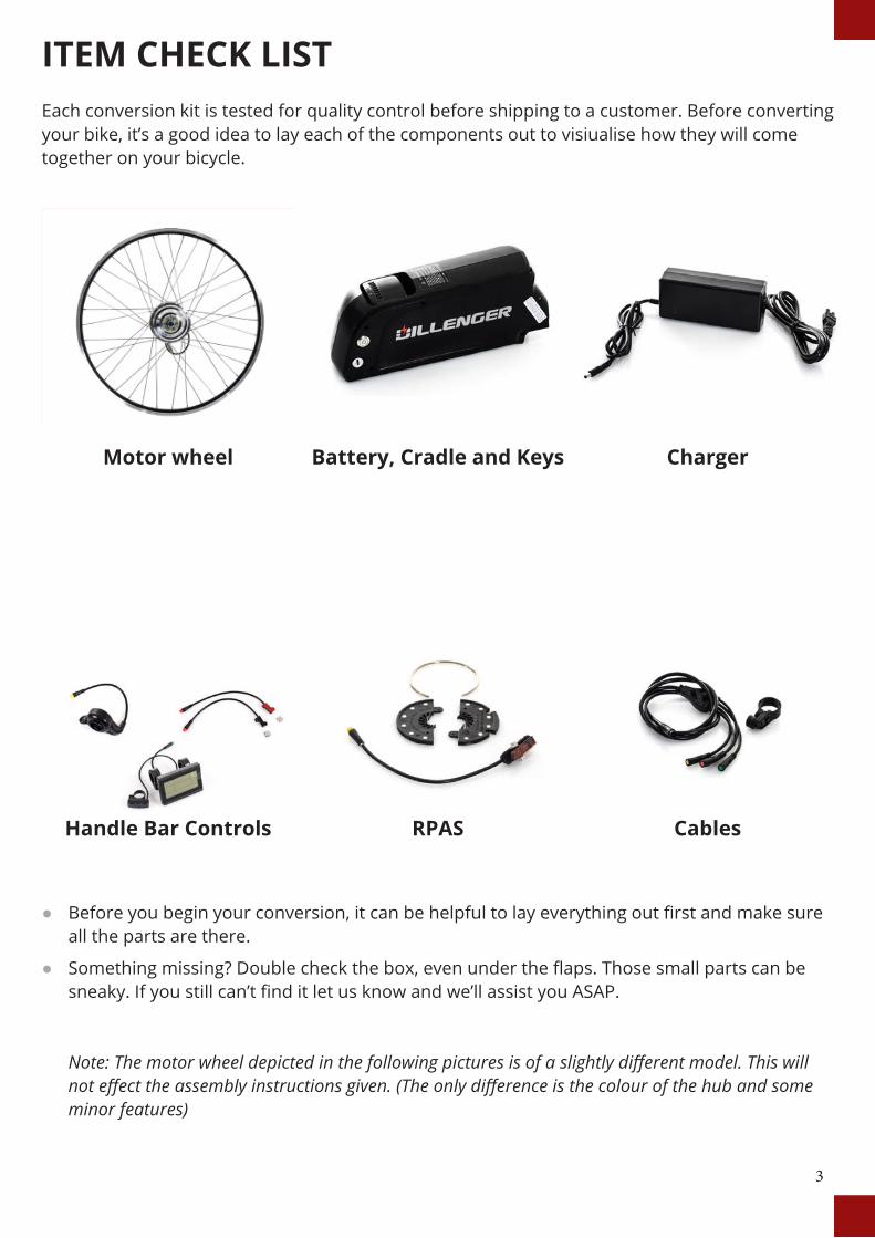
ITEM CHECK LISTEach conversion kit is tested for quality control before shipping to a customer. Before converting your bike, it’s a good idea to lay each of the components out to visiualise how they will come together on your bicycle.
● Before you begin your conversion, it can be helpful to lay everything out first and make sure all the parts are there.
● Something missing? Double check the box, even under the flaps. Those small parts can be sneaky. If you still can’t find it let us know and we’ll assist you ASAP. Note: The motor wheel depicted in the following pictures is of a slightly different model. This will not effect the assembly instructions given. (The only difference is the colour of the hub and some minor features)
Motor wheel
Handle Bar Controls
Battery, Cradle and Keys
RPAS
Charger
Cables
4
Contents
Item check list 3
Install overview 5
Installation process 6
Wheel Install 7
Battery Cradle Installation 8
Handlebar Controls 9
Display 9
Display Continued... 10
Thumb Throttle 11
E-Brake Sensors 12
Removable Pedal Assist Sensor (RPAS) 13
RPAS Continued... 14
Wiring Install 14
Tidy Up 15
Battery Operation 16
Charging 17
Maintenance and Care 18
Trouble Shooting 19
Trouble Shooting Continued... 20
Specifications 23
Contact us 24
5
INSTALL OVERVIEW
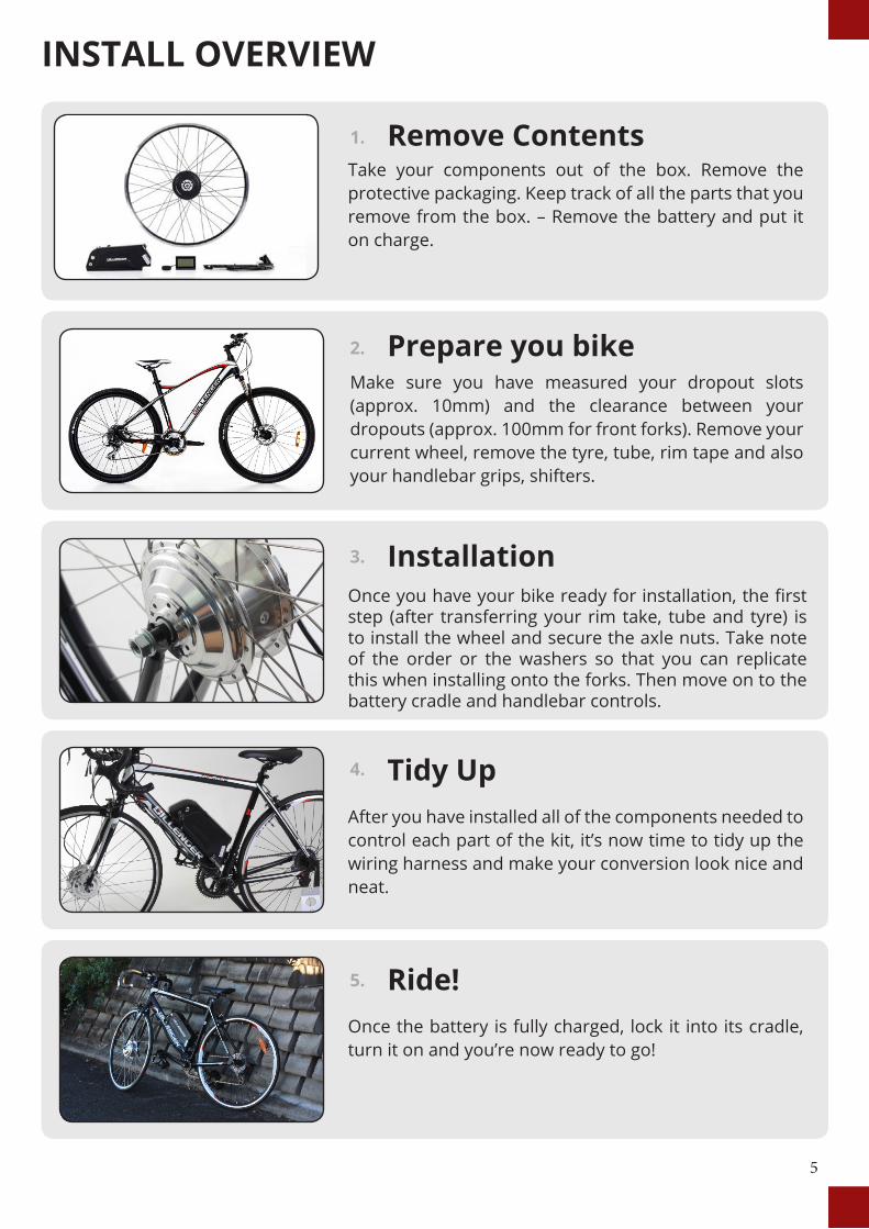
Remove ContentsTake your components out of the box. Remove the protective packaging. Keep track of all the parts that you remove from the box. – Remove the battery and put it on charge.
1.
InstallationOnce you have your bike ready for installation, the first step (after transferring your rim take, tube and tyre) is to install the wheel and secure the axle nuts. Take note of the order or the washers so that you can replicate this when installing onto the forks. Then move on to the battery cradle and handlebar controls.
3.
Ride!Once the battery is fully charged, lock it into its cradle, turn it on and you’re now ready to go!
5.
Prepare you bikeMake sure you have measured your dropout slots (approx. 10mm) and the clearance between your dropouts (approx. 100mm for front forks). Remove your current wheel, remove the tyre, tube, rim tape and also your handlebar grips, shifters.
2.
Tidy UpAfter you have installed all of the components needed to control each part of the kit, it’s now time to tidy up the wiring harness and make your conversion look nice and neat.
4.
6
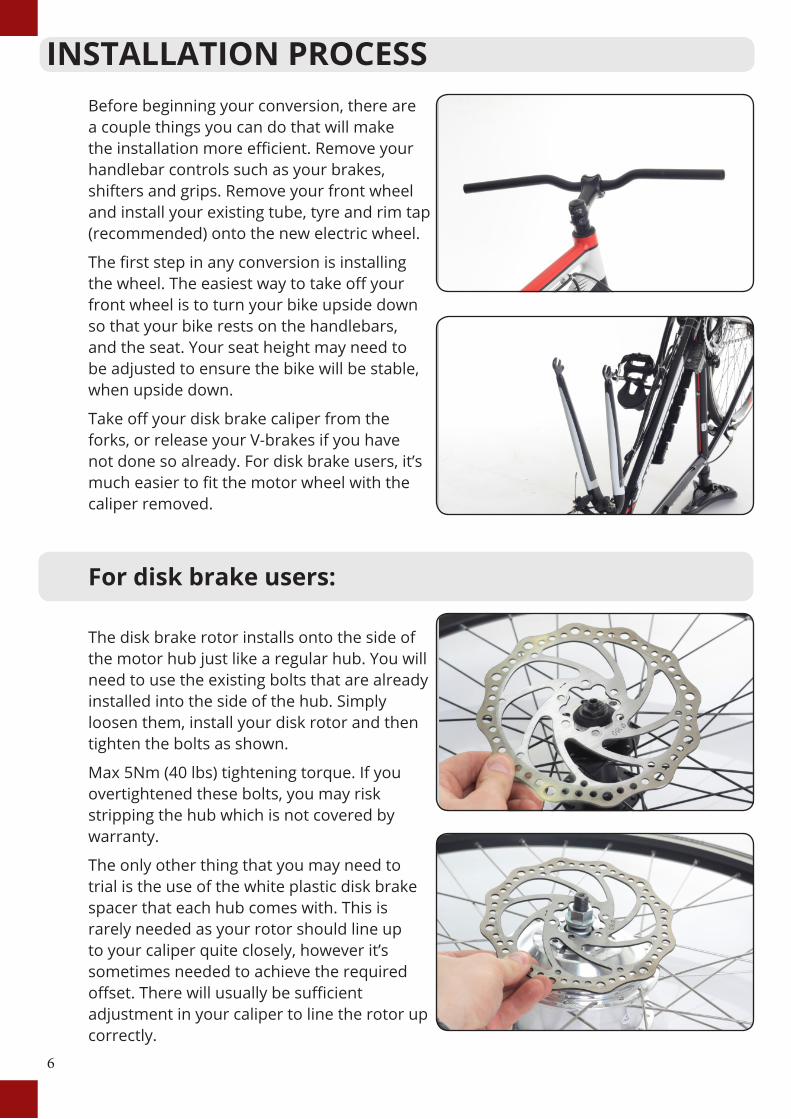
INSTALLATION PROCESSBefore beginning your conversion, there are a couple things you can do that will make the installation more efficient. Remove your handlebar controls such as your brakes, shifters and grips. Remove your front wheel and install your existing tube, tyre and rim tap (recommended) onto the new electric wheel.
The first step in any conversion is installing the wheel. The easiest way to take off your front wheel is to turn your bike upside down so that your bike rests on the handlebars, and the seat. Your seat height may need to be adjusted to ensure the bike will be stable, when upside down.
Take off your disk brake caliper from the forks, or release your V-brakes if you have not done so already. For disk brake users, it’s much easier to fit the motor wheel with the caliper removed.
For disk brake users:
The disk brake rotor installs onto the side of the motor hub just like a regular hub. You will need to use the existing bolts that are already installed into the side of the hub. Simply loosen them, install your disk rotor and then tighten the bolts as shown.
Max 5Nm (40 lbs) tightening torque. If you overtightened these bolts, you may risk stripping the hub which is not covered by warranty.
The only other thing that you may need to trial is the use of the white plastic disk brake spacer that each hub comes with. This is rarely needed as your rotor should line up to your caliper quite closely, however it’s sometimes needed to achieve the required offset. There will usually be sufficient adjustment in your caliper to line the rotor up correctly.
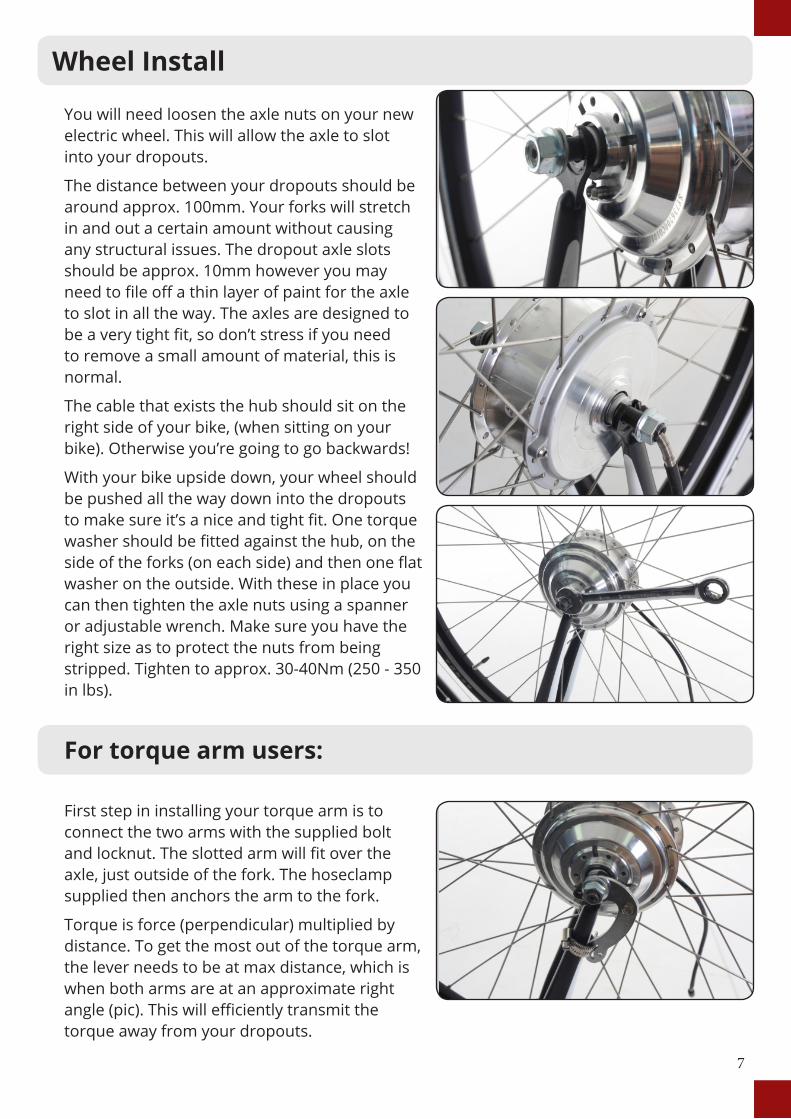
You will need loosen the axle nuts on your new electric wheel. This will allow the axle to slot into your dropouts.
The distance between your dropouts should be around approx. 100mm. Your forks will stretch in and out a certain amount without causing any structural issues. The dropout axle slots should be approx. 10mm however you may need to file off a thin layer of paint for the axle to slot in all the way. The axles are designed to be a very tight fit, so don’t stress if you need to remove a small amount of material, this is normal.
The cable that exists the hub should sit on the right side of your bike, (when sitting on your bike). Otherwise you’re going to go backwards!
With your bike upside down, your wheel should be pushed all the way down into the dropouts to make sure it’s a nice and tight fit. One torque washer should be fitted against the hub, on the side of the forks (on each side) and then one flat washer on the outside. With these in place you can then tighten the axle nuts using a spanner or adjustable wrench. Make sure you have the right size as to protect the nuts from being stripped. Tighten to approx. 30-40Nm (250 - 350 in lbs).
For torque arm users:
First step in installing your torque arm is to connect the two arms with the supplied bolt and locknut. The slotted arm will fit over the axle, just outside of the fork. The hoseclamp supplied then anchors the arm to the fork.
Torque is force (perpendicular) multiplied by distance. To get the most out of the torque arm, the lever needs to be at max distance, which is when both arms are at an approximate right angle (pic). This will efficiently transmit the torque away from your dropouts.
7
Wheel Install
You will need loosen the axle nuts on your new electric wheel. This will allow the axle to slot into your dropouts.
The distance between your dropouts should be around approx. 100mm. Your forks will stretch in and out a certain amount without causing any structural issues. The dropout axle slots should be approx. 10mm however you may need to file off a thin layer of paint for the axle to slot in all the way. The axles are designed to be a very tight fit, so don’t stress if you need to remove a small amount of material, this is normal.
The cable that exists the hub should sit on the right side of your bike, (when sitting on your bike). Otherwise you’re going to go backwards!
With your bike upside down, your wheel should be pushed all the way down into the dropouts to make sure it’s a nice and tight fit. One torque washer should be fitted against the hub, on the side of the forks (on each side) and then one flat washer on the outside. With these in place you can then tighten the axle nuts using a spanner or adjustable wrench. Make sure you have the right size as to protect the nuts from being stripped. Tighten to approx. 30-40Nm (250 - 350 in lbs).
For torque arm users:
First step in installing your torque arm is to connect the two arms with the supplied bolt and locknut. The slotted arm will fit over the axle, just outside of the fork. The hoseclamp supplied then anchors the arm to the fork.
Torque is force (perpendicular) multiplied by distance. To get the most out of the torque arm, the lever needs to be at max distance, which is when both arms are at an approximate right angle (pic). This will efficiently transmit the torque away from your dropouts.
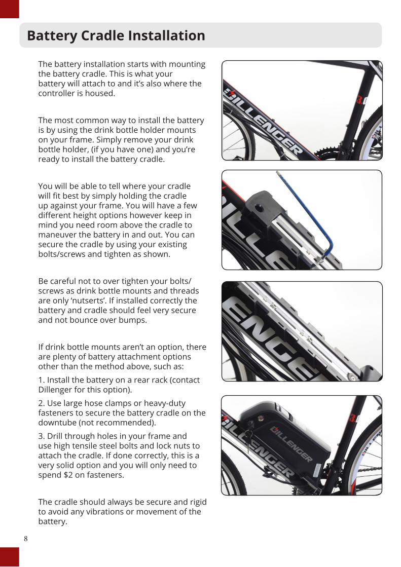
The battery installation starts with mounting the battery cradle. This is what your battery will attach to and it’s also where the controller is housed.
The most common way to install the battery is by using the drink bottle holder mounts on your frame. Simply remove your drink bottle holder, (if you have one) and you’re ready to install the battery cradle.
You will be able to tell where your cradle will fit best by simply holding the cradle up against your frame. You will have a few different height options however keep in mind you need room above the cradle to maneuver the battery in and out. You can secure the cradle by using your existing bolts/screws and tighten as shown.
Be careful not to over tighten your bolts/screws as drink bottle mounts and threads are only ‘nutserts’. If installed correctly the battery and cradle should feel very secure and not bounce over bumps.
If drink bottle mounts aren’t an option, there are plenty of battery attachment options other than the method above, such as:
1. Install the battery on a rear rack (contact Dillenger for this option).
2. Use large hose clamps or heavy-duty fasteners to secure the battery cradle on the downtube (not recommended).
3. Drill through holes in your frame and use high tensile steel bolts and lock nuts to attach the cradle. If done correctly, this is a very solid option and you will only need to spend $2 on fasteners.
The cradle should always be secure and rigid to avoid any vibrations or movement of the battery.
8
Battery Cradle Installation
9
Handlebar Controls
Display
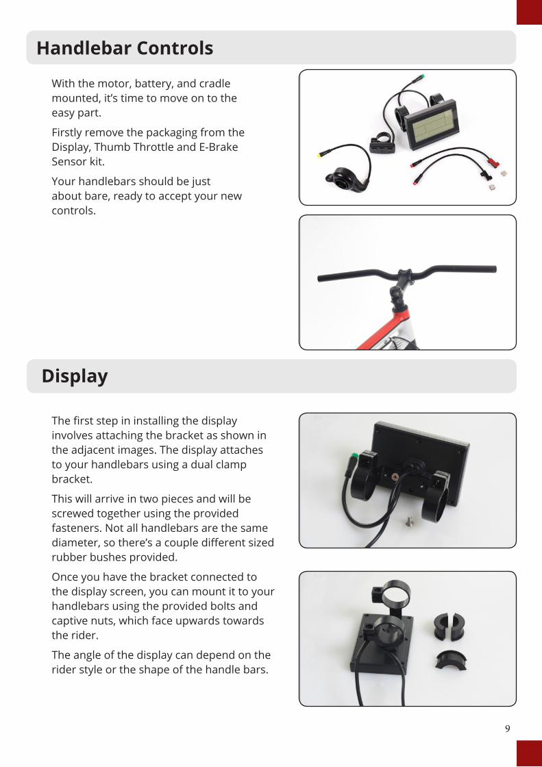
With the motor, battery, and cradle mounted, it’s time to move on to the easy part.
Firstly remove the packaging from the Display, Thumb Throttle and E-Brake Sensor kit.
Your handlebars should be just about bare, ready to accept your new controls.
The first step in installing the display involves attaching the bracket as shown in the adjacent images. The display attaches to your handlebars using a dual clamp bracket.
This will arrive in two pieces and will be screwed together using the provided fasteners. Not all handlebars are the same diameter, so there’s a couple different sized rubber bushes provided.
Once you have the bracket connected to the display screen, you can mount it to your handlebars using the provided bolts and captive nuts, which face upwards towards the rider.
The angle of the display can depend on the rider style or the shape of the handle bars.
10
Display Continued...
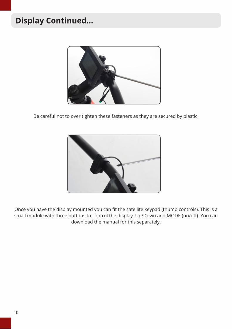
Be careful not to over tighten these fasteners as they are secured by plastic.
Once you have the display mounted you can fit the satellite keypad (thumb controls). This is a small module with three buttons to control the display. Up/Down and MODE (on/off). You can
download the manual for this separately.
11
Thumb Throttle Install
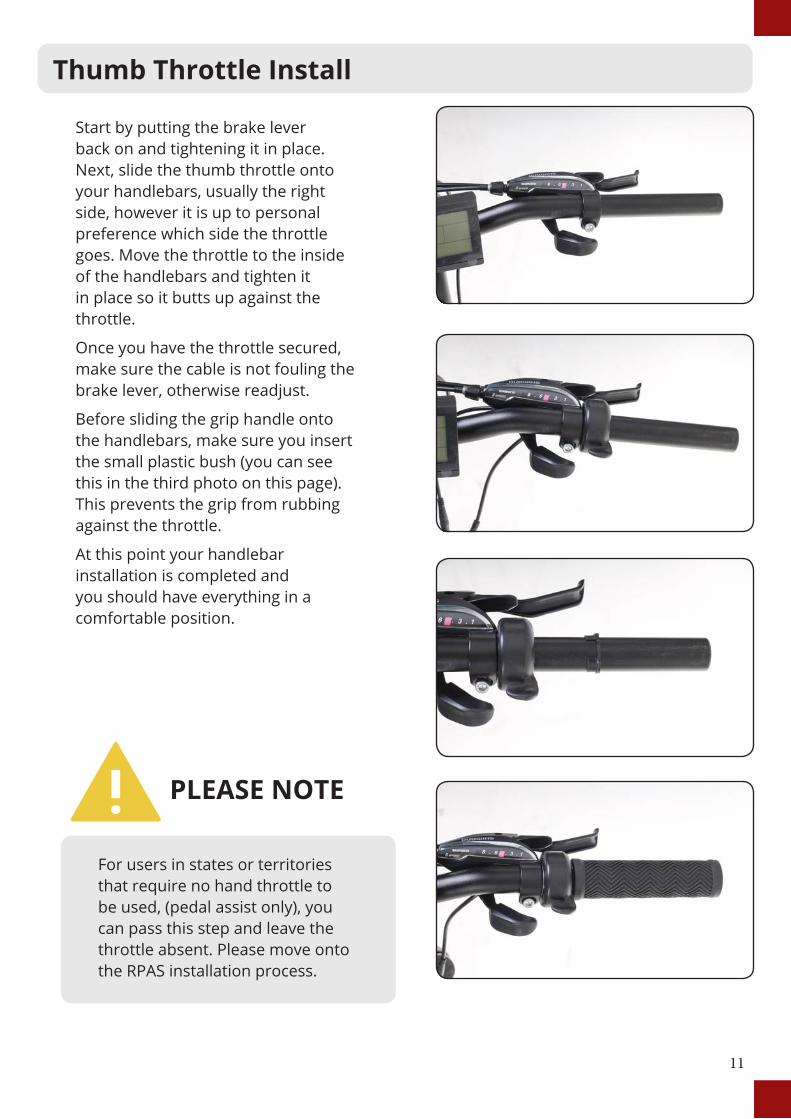
Start by putting the brake lever back on and tightening it in place. Next, slide the thumb throttle onto your handlebars, usually the right side, however it is up to personal preference which side the throttle goes. Move the throttle to the inside of the handlebars and tighten it in place so it butts up against the throttle.
Once you have the throttle secured, make sure the cable is not fouling the brake lever, otherwise readjust.
Before sliding the grip handle onto the handlebars, make sure you insert the small plastic bush (you can see this in the third photo on this page). This prevents the grip from rubbing against the throttle.
At this point your handlebar installation is completed and you should have everything in a comfortable position.
For users in states or territories that require no hand throttle to be used, (pedal assist only), you can pass this step and leave the throttle absent. Please move onto the RPAS installation process.
PLEASE NOTE
12
E-Brakes Sensors Install
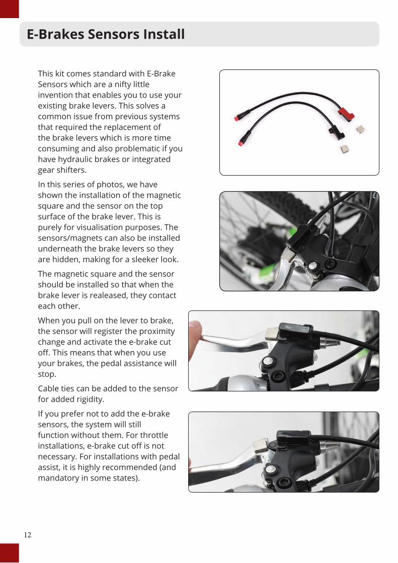
This kit comes standard with E-Brake Sensors which are a nifty little invention that enables you to use your existing brake levers. This solves a common issue from previous systems that required the replacement of the brake levers which is more time consuming and also problematic if you have hydraulic brakes or integrated gear shifters.
In this series of photos, we have shown the installation of the magnetic square and the sensor on the top surface of the brake lever. This is purely for visualisation purposes. The sensors/magnets can also be installed underneath the brake levers so they are hidden, making for a sleeker look.
The magnetic square and the sensor should be installed so that when the brake lever is realeased, they contact each other.
When you pull on the lever to brake, the sensor will register the proximity change and activate the e-brake cut off. This means that when you use your brakes, the pedal assistance will stop.
Cable ties can be added to the sensor for added rigidity.
If you prefer not to add the e-brake sensors, the system will still function without them. For throttle installations, e-brake cut off is not necessary. For installations with pedal assist, it is highly recommended (and mandatory in some states).

13
Removable Pedal Assist Sensor (RPAS)
The purpose of the pedal assist sensor is to generate a signal from the rotation of the crank that the controller processes to know that you’re pedaling and want some power!
How does this work? Magnets on the disk generate a changing magnetic field or a ‘hall effect’ and this is picked up by the hall effect sensor which transmits a signal to the controller. The pedal assist is the primary function of an electric bike and the level of assistance is adjustable on the handlebar LCD.
1. The sensor will need to line up very closely (under 5mm) to the RPAS disk.
2. Be sure to have the “working side” text facing the sensor. The RPAS is directional, so when you pedal backwards, the motor won’t engage (that would be dangerous and annoying!)
3. With the two halves of the disk mated together you can mount the silver circlip onto the disk, without jamming your fingers in the process (ideal, but not always possible).
4. When fitting the hall effect cadence sensor, the adhesive section is only there to hold it in place while you secure the sensor with cable ties provided.
Normally this step would involve the removal of the crank which can be quite complicated. Thanks to Dillenger’s innovative RPAS, this step is now a breeze!
To begin, have a look at the black plastic magnet wheel and the way the two halves join together. When you snap them together on the crank axle, (on your bike) you will then need to fit the steel circlip around the outside groove.
14
RPAS Continued...
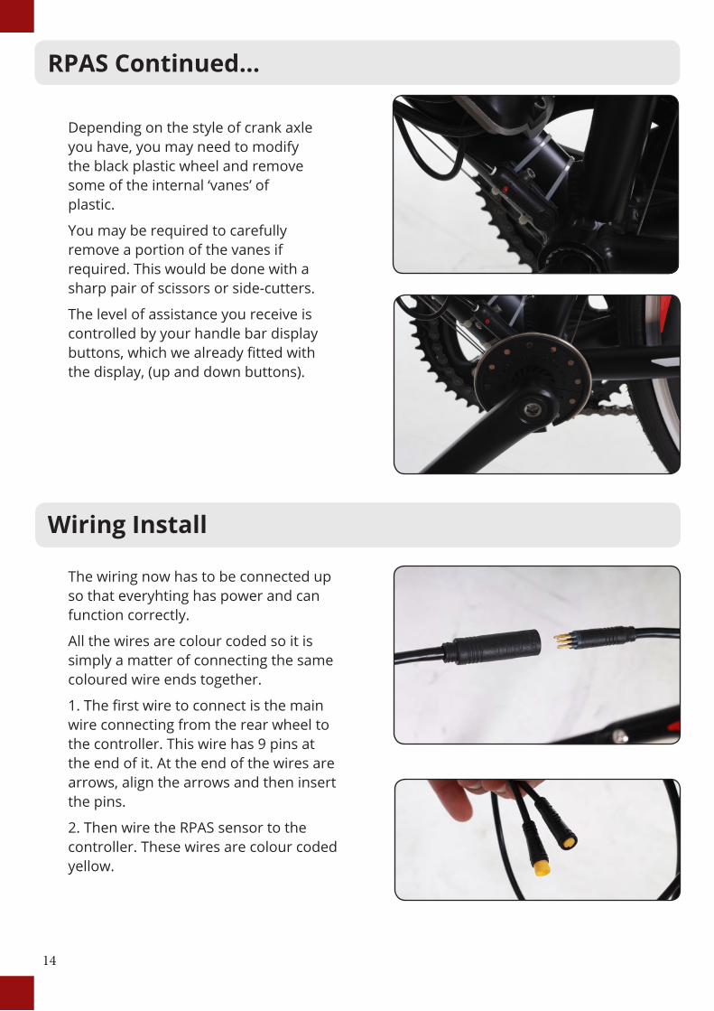
Depending on the style of crank axle you have, you may need to modify the black plastic wheel and remove some of the internal ‘vanes’ of plastic.
You may be required to carefully remove a portion of the vanes if required. This would be done with a sharp pair of scissors or side-cutters.
The level of assistance you receive is controlled by your handle bar display buttons, which we already fitted with the display, (up and down buttons).
Wiring Install
The wiring now has to be connected up so that everyhting has power and can function correctly.
All the wires are colour coded so it is simply a matter of connecting the same coloured wire ends together.
1. The first wire to connect is the main wire connecting from the rear wheel to the controller. This wire has 9 pins at the end of it. At the end of the wires are arrows, align the arrows and then insert the pins.
2. Then wire the RPAS sensor to the controller. These wires are colour coded yellow.
15
Tidy Up
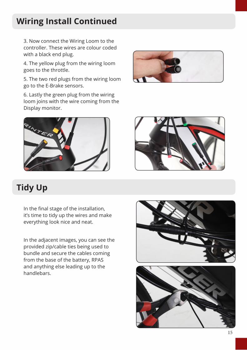
In the final stage of the installation, it’s time to tidy up the wires and make everything look nice and neat.
In the adjacent images, you can see the provided zip/cable ties being used to bundle and secure the cables coming from the base of the battery, RPAS and anything else leading up to the handlebars.
Wiring Install Continued
3. Now connect the Wiring Loom to the controller. These wires are colour coded with a black end plug.
4. The yellow plug from the wiring loom goes to the throttle.
5. The two red plugs from the wiring loom go to the E-Brake sensors.
6. Lastly the green plug from the wiring loom joins with the wire coming from the Display monitor.
16
Battery Operation
PLEASE NOTEEven with the battery locked in and turned off, the bike should be locked using a high quality bike lock.
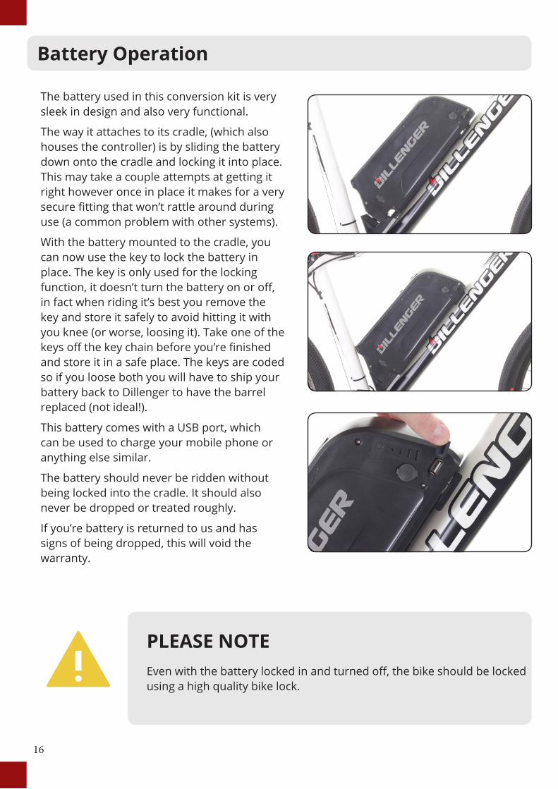
The battery used in this conversion kit is very sleek in design and also very functional.
The way it attaches to its cradle, (which also houses the controller) is by sliding the battery down onto the cradle and locking it into place. This may take a couple attempts at getting it right however once in place it makes for a very secure fitting that won’t rattle around during use (a common problem with other systems).
With the battery mounted to the cradle, you can now use the key to lock the battery in place. The key is only used for the locking function, it doesn’t turn the battery on or off, in fact when riding it’s best you remove the key and store it safely to avoid hitting it with you knee (or worse, loosing it). Take one of the keys off the key chain before you’re finished and store it in a safe place. The keys are coded so if you loose both you will have to ship your battery back to Dillenger to have the barrel replaced (not ideal!).
This battery comes with a USB port, which can be used to charge your mobile phone or anything else similar.
The battery should never be ridden without being locked into the cradle. It should also never be dropped or treated roughly.
If you’re battery is returned to us and has signs of being dropped, this will void the warranty.
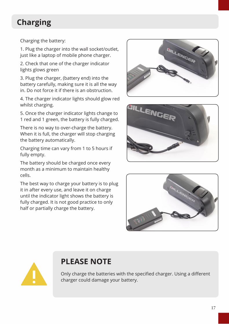
Charging the battery:
1. Plug the charger into the wall socket/outlet, just like a laptop of mobile phone charger.
2. Check that one of the charger indicator lights glows green
3. Plug the charger, (battery end) into the battery carefully, making sure it is all the way in. Do not force it if there is an obstruction.
4. The charger indicator lights should glow red whilst charging.
5. Once the charger indicator lights change to 1 red and 1 green, the battery is fully charged.
There is no way to over-charge the battery. When it is full, the charger will stop charging the battery automatically.
Charging time can vary from 1 to 5 hours if fully empty.
The battery should be charged once every month as a minimum to maintain healthy cells.
The best way to charge your battery is to plug it in after every use, and leave it on charge until the indicator light shows the battery is fully charged. It is not good practice to only half or partially charge the battery.
17
Charging
PLEASE NOTEOnly charge the batteries with the specified charger. Using a different charger could damage your battery.
Charging the battery:
1. Plug the charger into the wall socket/outlet, just like a laptop of mobile phone charger.
2. Check that one of the charger indicator lights glows green
3. Plug the charger, (battery end) into the battery carefully, making sure it is all the way in. Do not force it if there is an obstruction.
4. The charger indicator lights should glow red whilst charging.
5. Once the charger indicator lights change to 1 red and 1 green, the battery is fully charged.
There is no way to over-charge the battery. When it is full, the charger will stop charging the battery automatically.
Charging time can vary from 1 to 5 hours if fully empty.
The battery should be charged once every month as a minimum to maintain healthy cells.
The best way to charge your battery is to plug it in after every use, and leave it on charge until the indicator light shows the battery is fully charged. It is not good practice to only half or partially charge the battery.
18
Maintenance and Care
PLEASE NOTEAny modifications to your conversion kit that aren’t part of this manual will void your warranty.
Keep your bike clean! There’s nothing worse than having to work on a dirty bike...
Also keep in mind the usual bike maintenance like tyre pressures, brake pads, etc...
The motor in this kit is a sealed unit and requires no maintenance during its design life.
Lastly (just to reiterate) it’s important that you charge the battery at least once every month to ensure the battery maintains a safe storage level.
A little extra maintenance is required over and above a normal bicycle.
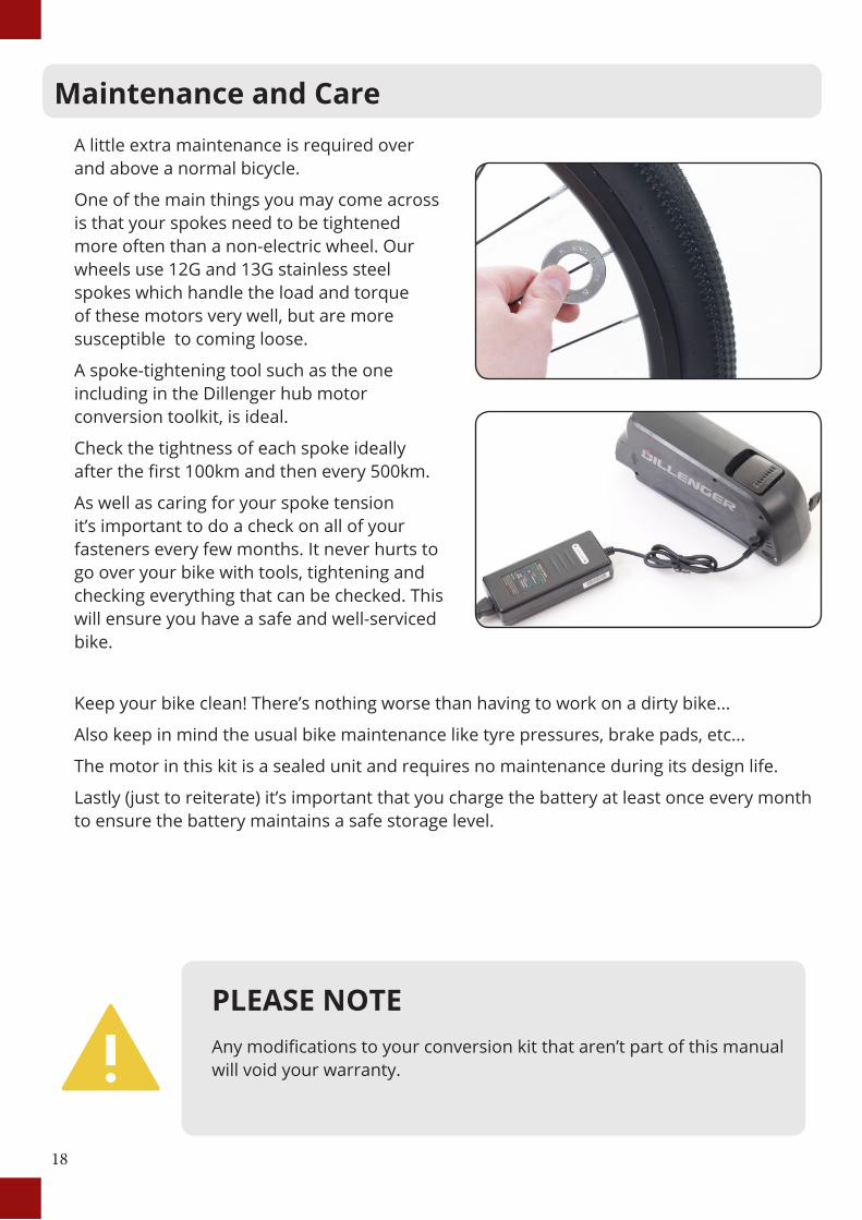
One of the main things you may come across is that your spokes need to be tightened more often than a non-electric wheel. Our wheels use 12G and 13G stainless steel spokes which handle the load and torque of these motors very well, but are more susceptible to coming loose.
A spoke-tightening tool such as the one including in the Dillenger hub motor conversion toolkit, is ideal.
Check the tightness of each spoke ideally after the first 100km and then every 500km.
As well as caring for your spoke tension it’s important to do a check on all of your fasteners every few months. It never hurts to go over your bike with tools, tightening and checking everything that can be checked. This will ensure you have a safe and well-serviced bike.
19
Trouble Shooting
Fault Solution
Display turns on, but motor does not Activate
Check the motor plug from the controller. This is a very stiff connection and will not work unless the plug is all the way in to the indicator line. The twisting of the handlebars can sometimes cause the plug to pull out slightly if there is not enough slack in the motor cable.
Motor runs backwards Remove the motor from the forks and switch the direction.
Motor feels like it has something caught inside or some kind of brake on inside
Remove the disk brake bolts completely and see if this remedies the issue. If the disk brake bolts are too long, they will go too far into the housing and fowl against the internals.
A high pitched rattling noise can be heard when accelerating
The vibration of the motor is very small, but at this frequency it can do some odd things to the other components on the bike if they are loose. For example a loose spoke or even a bolt on your rear rack. If something is just a little bit loose, sometimes this can reverberate and make a harsh high pitch rattling sound. Nothing is broken or wrong, you just have to identify the loose part!
Rim has a buckle or spokes coming loose all the time
We would recommend a competent wheel builder to fix any major spoke tension issues, however there are some really good youtube tutorials on how to adjust spoke tension.
Spokes has snapped or missing
Dillenger stocks spare spokes for very reasonable prices, just check out our spares section online and you can find the right type and length for your kit.
Dillenger’s troubleshooting advice will take you through a logical way to diagnose any issues that may arise during installation and use.
Before commencing troubleshooting, disconnect all components. Do not short cut this process. There are countless times a loose plug has caused grief. By disconnecting all the plugs and then reconnecting just the crucial components, this will solve any loose plug issue.
Go through one by one plugging in the other components (such as the PAS or the e-brake handles) to see if any of these are the cause of the problem. In this basic state you may discover the culprit quickly.
20
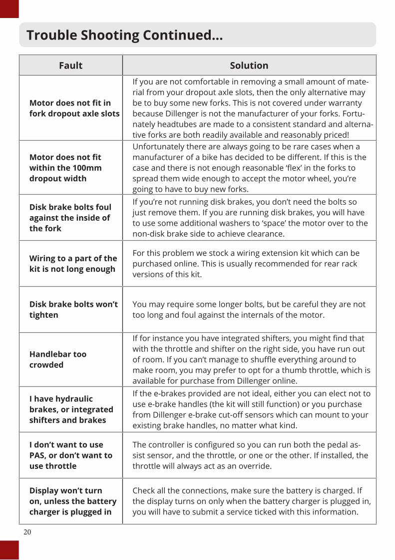
Trouble Shooting Continued...
Fault Solution
Motor does not fit in fork dropout axle slots
If you are not comfortable in removing a small amount of mate-rial from your dropout axle slots, then the only alternative may be to buy some new forks. This is not covered under warranty because Dillenger is not the manufacturer of your forks. Fortu-nately headtubes are made to a consistent standard and alterna-tive forks are both readily available and reasonably priced!
Motor does not fit within the 100mm dropout width
Unfortunately there are always going to be rare cases when a manufacturer of a bike has decided to be different. If this is the case and there is not enough reasonable ‘flex’ in the forks to spread them wide enough to accept the motor wheel, you’re going to have to buy new forks.
Disk brake bolts foul against the inside of the fork
If you’re not running disk brakes, you don’t need the bolts so just remove them. If you are running disk brakes, you will have to use some additional washers to ‘space’ the motor over to the non-disk brake side to achieve clearance.
Wiring to a part of the kit is not long enough
For this problem we stock a wiring extension kit which can be purchased online. This is usually recommended for rear rack versions of this kit.
Disk brake bolts won’t tighten
You may require some longer bolts, but be careful they are not too long and foul against the internals of the motor.
Handlebar too crowded
If for instance you have integrated shifters, you might find that with the throttle and shifter on the right side, you have run out of room. If you can’t manage to shuffle everything around to make room, you may prefer to opt for a thumb throttle, which is available for purchase from Dillenger online.
I have hydraulic brakes, or integrated shifters and brakes
If the e-brakes provided are not ideal, either you can elect not to use e-brake handles (the kit will still function) or you purchase from Dillenger e-brake cut-off sensors which can mount to your existing brake handles, no matter what kind.
I don’t want to use PAS, or don’t want to use throttle
The controller is configured so you can run both the pedal as-sist sensor, and the throttle, or one or the other. If installed, the throttle will always act as an override.
Display won’t turn on, unless the battery charger is plugged in
Check all the connections, make sure the battery is charged. If the display turns on only when the battery charger is plugged in, you will have to submit a service ticked with this information.
21
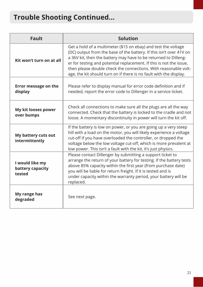
Fault Solution
Kit won’t turn on at all
Get a hold of a multimeter ($15 on ebay) and test the voltage (DC) output from the base of the battery. If this isn’t over 41V on a 36V kit, then the battery may have to be returned to Dilleng-er for testing and potential replacement. If this is not the issue, then please double check the connections. With reasonable volt-age, the kit should turn on if there is no fault with the display.
Error message on the display
Please refer to display manual for error code definition and if needed, report the error code to Dillenger in a service ticket.
My kit looses power over bumps
Check all connections to make sure all the plugs are all the way connected. Check that the battery is locked to the cradle and not loose. A momentary discontinuity in power will turn the kit off.
My battery cuts out intermittently
If the battery is low on power, or you are going up a very steep hill with a load on the motor, you will likely experience a voltage cut-off if you have overloaded the controller, or dropped the voltage below the low voltage cut-off, which is more prevalent at low power. This isn’t a fault with the kit, it’s just physics.
I would like my battery capacity tested
Please contact Dillenger by submitting a support ticket toarrange the return of your battery for testing. If the battery tests above 85% capacity within the first year (from purchase date) you will be liable for return freight. If it is tested and is under capacity within the warranty period, your battery will be replaced.
My range has degraded See next page.
Trouble Shooting Continued...
22
Range extension:
If you’re not getting the approximate quoted range out of your e-bike system, take the following steps:
1. Pedal assist sensor
If you haven’t installed the pedal assist sensor, you might not get the required range out of your kit. The pedal assist modes only work for pedal assist input, not throttle. If you use the throttle on low levels of pedal assist, this will not make any difference. Pedal assist levels are only for pedal assist. The throttle is great fun to use, but even moderate use of the throttle, with pedaling, is still going to burn through the juice a lot faster than on a low-medium pedal assist setting.
2. Battery indicator lights – full charge. The LED and LCD battery level displays are a basic indication of battery charge, but they are based on voltage which is variable and not a true indication of battery capacity. The only accurate indication of a full charge, is having charged the battery and the battery charger lights glowing green to indicate that the battery is fully charged.
3. LED/LCD indicator light – running low
Some customers find that the LED/LCD charge indicator can lead them astray in terms of how far the bike will go on low power. You don’t risk damaging the system by riding all the way to the controller low voltage cutoff. Keep riding on pedal assist even after the last battery indicator bar starts blinking.
4. Hills/riding style/other factors
a. The ranges quoted are from real world testing, with some hills and some flat areas. If your commute involves a lot of hills, that’s going to impact on the range of the kit. 1,000W kits are especially susceptible to being drained a lot more on hills (more than 250’s anyway). If you need to purchase a second charger to charge the battery at half way, or if you need an additional battery, they will be available for purchase online.
5. General tips
• Make sure the wheels are running free (rubbing brakes can halve your range quite easily)
• Keep the battery topped up between uses
• Make sure the tyre pressures are at optimum
• Pedal harder when taking off and select the right gear for assisting up hills
If you would like to submit a Dillenger service ticket, please go to this URL:
https://dillenger.zendesk.com/hc/en-us/requests/new
Trouble Shooting Continued...
23
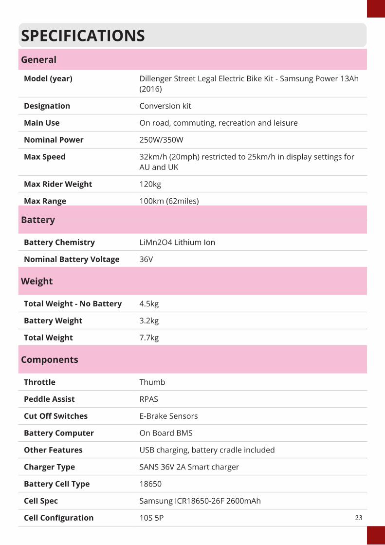
SPECIFICATIONS
Battery
Battery Chemistry LiMn2O4 Lithium Ion
Nominal Battery Voltage 36V
General
Model (year) Dillenger Street Legal Electric Bike Kit - Samsung Power 13Ah (2016)
Designation Conversion kit
Main Use On road, commuting, recreation and leisure
Nominal Power 250W/350W
Max Speed 32km/h (20mph) restricted to 25km/h in display settings for AU and UK
Max Rider Weight 120kg
Max Range 100km (62miles)
Weight
Total Weight - No Battery 4.5kg
Battery Weight 3.2kg
Total Weight 7.7kg
Components
Throttle Thumb
Peddle Assist RPAS
Cut Off Switches E-Brake Sensors
Battery Computer On Board BMS
Other Features USB charging, battery cradle included
Charger Type SANS 36V 2A Smart charger
Battery Cell Type 18650
Cell Spec Samsung ICR18650-26F 2600mAh
Cell Configuration 10S 5P

24
CONTACT US
Dillenger Head Office3/13 Olympic CircuitSouthportQLD 4215AUSTRALIATel.: +617 5532 9235dillenger.zendesk.comwww.dillengerelectricbikes.com
© Dillenger 2016