Embed Size (px)
Citation preview

User ManualV2.0
Ecliptech Innovations Pty. Ltd

1 2
INTRODUCTION ...................................................................................................... 2
BASIC FEATURES ................................................................................................... 3
Calibration Value ...................................................................................... 3
Setting Your Shift-Points .......................................................................... 4
Display Mode ........................................................................................... 5
Automatic Battery Voltage Indication ........................................................ 6
ADVANCED FEATURES ........................................................................................... 7
Brightness Control ................................................................................... 7
RPM Step Size ......................................................................................... 8
Running In Battery Mode ......................................................................... 9
Battery Voltage Calibration ....................................................................... 9
ADVANCED SETTINGS MENU ............................................................................... 10
Startup Display ...................................................................................... 11
Cruise Mode Timer ................................................................................. 12
RPM Hysteresis ...................................................................................... 13
Over Voltage Warning ............................................................................. 14
Sensitivity .............................................................................................. 15
RPM Input Delay .................................................................................... 16
Engine Stall Alert ................................................................................... 17
Temperature Protection .......................................................................... 18
System Reset ........................................................................................ 18
Shift-I™ is a progressive gear shift and RPM range gauge. The seven lights are used to display a section of your RPM, the first light turning on at your programmed low RPM point, and depending on the display mode, all lights flashing at your programmed high RPM point.
Typically the low RPM is set where the torque starts to kick in, and the high RPM point is set at the shift point. The example dyno chart below illustrates useful RPM set-points. Straight line gear shifting can become more consistent, not only from the flashing display indicating when to shift, but the progressive increase allows the driver to anticipate the shift.
Knowing the optimal RPM range can be particularly useful for both circuit and street driving. It can indicate if your entry RPM is below the start of the power curve, and also indicates if your RPM is getting too high to accelerate out of the turn or make a pass cleanly without a gear change.
The Shift-I can be used to optimize launch control by keeping the RPM in the ideal range. Break out of old habits by fine tuning for optimal RPM set-points; form better driving habits and control.
Why seven lights? In your peripheral vision you can instantly and easily recognize how many of the seven lights are on. With more lights, concentration is required.
POW
ER h
p
TORQUE lb.ft
RPM
EXAMPLE DYNO CHART Shift Point First Light
Index Introduction
3 4
Calibration Value
The RPM signal varies between different vehicle models and ignition systems. A “Calibration” setting is used to match the Shift-I with your vehicle. Using the correct setting is VERY important, as many of the functions are dependent on the RPM value. Most functions are locked out if the RPM is above 2,200!
The easiest way to determine the correct calibration setting is simply to try it! The unit is delivered with a calibration value of 0.5 and set for the lights to turn on at what the Shift-I believes is 1,000, 2,000, 3,000 RPM etc…
Start the engine and increase the RPM slowly to check if the first light comes on near 1,000 RPM, the second at 2,000 RPM, third at 3,000 RPM etc. If the first light does indeed come on or near 1,000 RPM, then the default calibration value is correct. Keep in mind that many tachos are not accurate.
If the lights turn on too soon, then the calibration value must be increased.If they turn on too late, then it must be decreased.
Changing the Calibration: With the ignition off, press and hold both buttons, turn ignition on and then release. If it is the first time you have entered this mode, you will see the first light flashing, indicating 0.5. Press up or down to change the calibration. Press both buttons to save the change. You can re-enter the calibration mode to verify your setting.
1 light flashing à Calibration = 0.5
Setting Your Shift-Points
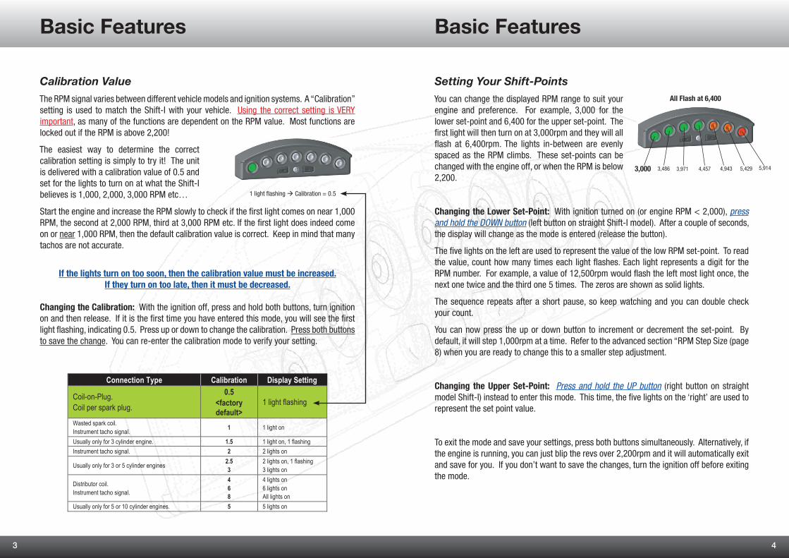
You can change the displayed RPM range to suit your engine and preference. For example, 3,000 for the lower set-point and 6,400 for the upper set-point. The first light will then turn on at 3,000rpm and they will all flash at 6,400rpm. The lights in-between are evenly spaced as the RPM climbs. These set-points can be changed with the engine off, or when the RPM is below 2,200.
Changing the Lower Set-Point: With ignition turned on (or engine RPM < 2,000), press and hold the DOWN button (left button on straight Shift-I model). After a couple of seconds, the display will change as the mode is entered (release the button).
The five lights on the left are used to represent the value of the low RPM set-point. To read the value, count how many times each light flashes. Each light represents a digit for the RPM number. For example, a value of 12,500rpm would flash the left most light once, the next one twice and the third one 5 times. The zeros are shown as solid lights.
The sequence repeats after a short pause, so keep watching and you can double check your count.
You can now press the up or down button to increment or decrement the set-point. By default, it will step 1,000rpm at a time. Refer to the advanced section “RPM Step Size (page 8) when you are ready to change this to a smaller step adjustment.
Changing the Upper Set-Point: Press and hold the UP button (right button on straight model Shift-I) instead to enter this mode. This time, the five lights on the ‘right’ are used to represent the set point value.
To exit the mode and save your settings, press both buttons simultaneously. Alternatively, if the engine is running, you can just blip the revs over 2,200rpm and it will automatically exit and save for you. If you don’t want to save the changes, turn the ignition off before exiting the mode.
5,914
All Flash at 6,400
3,000 5,4294,9434,4573,9713,486
Connection Type Calibration Display Setting
Coil-on-Plug. Coil per spark plug.
0.5 <factory default>
1 light flashing
Wasted spark coil. Instrument tacho signal. 1 1 light on
Usually only for 3 cylinder engine. 1.5 1 light on, 1 flashing Instrument tacho signal. 2 2 lights on
Usually only for 3 or 5 cylinder engines 2.5 3
2 lights on, 1 flashing 3 lights on
Distributor coil. Instrument tacho signal.
4 6 8
4 lights on 6 lights on All lights on
Usually only for 5 or 10 cylinder engines. 5 5 lights on
Basic Features Basic Features

5 6
Display Mode
Shift-I™ has 12 display modes to choose from, based around 5 categories…
Mode .............. DescriptionOff ................... Display is turned off.Cumulative ...... The lights turn on and stay on as the RPM increases.Dot ................. Only one light on at a time.Shift Only ......... Lights flash at shift point only.Special ............ High contrast, suitable for staging and high performance engines.
There are variations to some of these modes, whereby at the upper RPM set-point the display will flash the last light or all lights.
You can cycle through these modes by using the up and down buttons. The display will demonstrate the selected mode with a quick animation, and then automatically save your selection.
…IMPORTANT…
If the RPM is above 2,200, any button press will toggle the display on/off.
The display mode used is personal preference; however the cumulative and high contrast modes are often the preferred choice.
If you cycle down to the first display mode, you will see a very quick animation of the lights turning off. This mode keeps the display off.
You should never operate this product while driving and/or when it is not safe to do so.
Automatic Battery Voltage Indication
Shift-I™ also provides a battery voltage indication. This feature is an aid to evaluating the conidition of the battery and detecting problems with the vehicles ignition voltage regulation.
The seven lights represent 9 to 15 volts. The first light on the left will turn on when the voltage is 9 or greater, the second light 10 volts or greater etc…
The battery voltage is displayed when ignition is turned on. You can adjust/disable this, see page 11.
With the engine off, a battery in good condition and well charged will typically register ~12.5V. However, this is dependent on many factors, such as the temperature of the battery and if it is supplying current (such as to headlights).
Assuming a battery voltage of 12.5V, four of the lights will be on. As you start the engine, the starter motor draws a lot of current from the battery and its voltage will temporarily drop. Gauging the health of a battery can be done while it’s under cranking load. Typically while cranking there will be a 1 or 2 volts drop, which you will see on the display. If the battery is not in good condition, and/or low on charge, you will notice the voltage dropping further.
Once the engine is started, it will typically generate ~13-14.5V at idle and possibly up to ~15V at higher RPMs. Refer to your vehicles specifications for more accurate expectations. Higher voltages may indicate a failure of the charging circuit, and prolonged exposure may cause damage to the vehicles electrics and battery.
The battery voltage display is for general use only, and used only to assist fault detection and diagnosis. The accuracy of the indicated voltage may not be accurate, and the voltage registered at the Shift-I™ may be different to the actual voltage at the battery.
Please refer to the advanced section for more detailed information about how this feature is calibrated (page 9). This mode will automatically exit ~3 seconds after an attempt to start the engine is made, or if either button is pressed.
Voltage Scale
Ignition On
Engine Running
>14V>13V>12V
>12V
>14V
>9V >15V>11V>10V
Low Battery Voltage
>16V if flashing
Basic Features Basic Features

7 8
Brightness Control
The brightness of the lights changes with the ambient light to maintain optimum visibility. When dark, they go dim, when light they go bright. However, you can customize how bright they are in various conditions.
Adjusting the Brightness: Ensure ignition is on and press both buttons at once. If you are in another mode, such as adjusting RPM set-points or battery watch, you must first exit those modes. On entering the mode, all 7 lights will turn on. Use the up and down buttons to change the brightness. Each time an adjustment is made, the display will blink, except if it is already at the minimum or maximum brightness setting. Press and hold a button to adjust quickly.
To exit the mode and save the changes, press both buttons at once. Alternatively, if no further adjustment is made for 4 seconds, the Shift-I™ will automatically save your current settings and exit.
Shift-I™ maintains an intelligent brightness map, which translates the ambient light to your preferences in display brightness. When you set the brightness, you are setting the brightness for a particular ambient light. So if the sun is shining bright and you adjust the brightness, it won’t affect adjustments you previously made when it was dark.
This feature can be used to set the display to full brightness all the time, or perhaps the lowest level in the dark and only ½ brightness at daylight. You cannot however set the display to be brighter in the dark than it is in the light. Shift-I™ will automatically adjust the map to maintain this rule. When adjusting the brightness, avoid obscuring the light sensor while pressing the buttons. Doing so can cause an unexpected adjustment.
NOTE:
The brightness of the display should be checked in all light conditions to ensure it does not blind or obscure your view before use. Do not expect the unit to transition between dark and light areas quickly, such as going through an unlit tunnel on a bright day. The brightness level will take a few seconds to adjust to the light conditions, which is also dependent on its location and the ambient light reaching the light sensor. Other vehicles headlights can also trick the light sensor, and therefore its placement should be appropriately selected. Disconnect the unit if any malfunction occurs or is suspected.
Light Sensor
RPM Step SizeWith the default setting, the upper and lower RPM set-points are incremented or decremented in 1,000rpm steps. Once you have the display RPM range set close, reduce the step size so you can fine tune further.
Available RPM Step Sizes4,0002,0001,00050025010050
Changing the RPM Step Size: To change the step size, press and hold the up button and turn ignition on. The display will show the step size in the same format as setting your lower shift point. Press up or down to change the step size. To save the new setting and exit, press both buttons simultaneously. If you don’t want to save changes, turn ignition off when safe to do so.
If the step size is set too small, it becomes time consuming to change the upper and lower RPM set-points. For engines with a lower redline <10,000rpm, 100rpm is a good practical setting. For example, for commuting you may set the RPM range at 2,600 to 5,700rpm, however for racing on the track a more useful setting may be 3,500rpm to 6,300rpm.
The step size can be changed without affecting your current upper and lower RPM set-points. However, when you increment or decrement a set-point, it will automatically align to the next multiple. For example, if you have your upper set-point at 6,250rpm, and then set the step size to 100rpm, the next increment will go the next highest multiple, 6,300rpm.
Changing the step size does NOT affect the accuracy.
(default)
Advanced Features Advanced Features
9 10
Running In Battery Mode
This feature enables battery voltage to be continuously monitored, instead of RPM. To enter this mode, press and hold the down button (left on straight model Shift-I) and turn ignition on. To exit the mode, either press a button or turn ignition off when safe to do so.
The 7 lights represent 9 to 15V, as shown on page 6. In addition, if the voltage goes above 16V the light on the far right will flash immediately, or if the voltage goes below 9V, the light on the far left will flash immediately. This mode may be useful to see how the charging and regulation circuitry is functioning. This feature is particularly useful at catching intermittent problems.
Battery Voltage Calibration
The ignition voltage supplied to the Shift-I™ unit may be lower than the actual voltage at the battery. This is often the case when the same ignition circuit also powers something like the headlights, where large currents cause larger voltage drops in the wires. The “Battery Voltage Calibration” can be used to offset the difference.
Calibration allows for correcting up to ±2.0V, in 0.1V intervals. To perform the calibration, you will need a voltage meter. With ignition on, measure the voltage at the battery and at the Shift-I™. As an example, you may get 12.5V and 12.1V respectively. This example has a 0.4V drop.
Use the following method to adjust the calibration..1. Enter Running in Battery Mode described above (hold the down button and turn
ignition on).2. First, reset the calibration to zero by pressing and holding both buttons until you
see a quick flash of the lights, then release. 3. To add a 0.1V offset, press & hold the up button until you see a quick flash of the
lights, then release. To subtract 0.1V, use the down button instead.4. Repeat step 3 until the desired offset is reached. In the previous example, with a
0.4V drop you would add four 0.1V offsets.5. To save the results, momentarily press either button. If you don’t want to save the
setting, turn ignition off (when safe to do so).
Incorrect adjustment could result in the over voltage warning being triggered falsely.
Advanced Settings Menu
The advanced settings have been made available for those feeling the need to tweak!
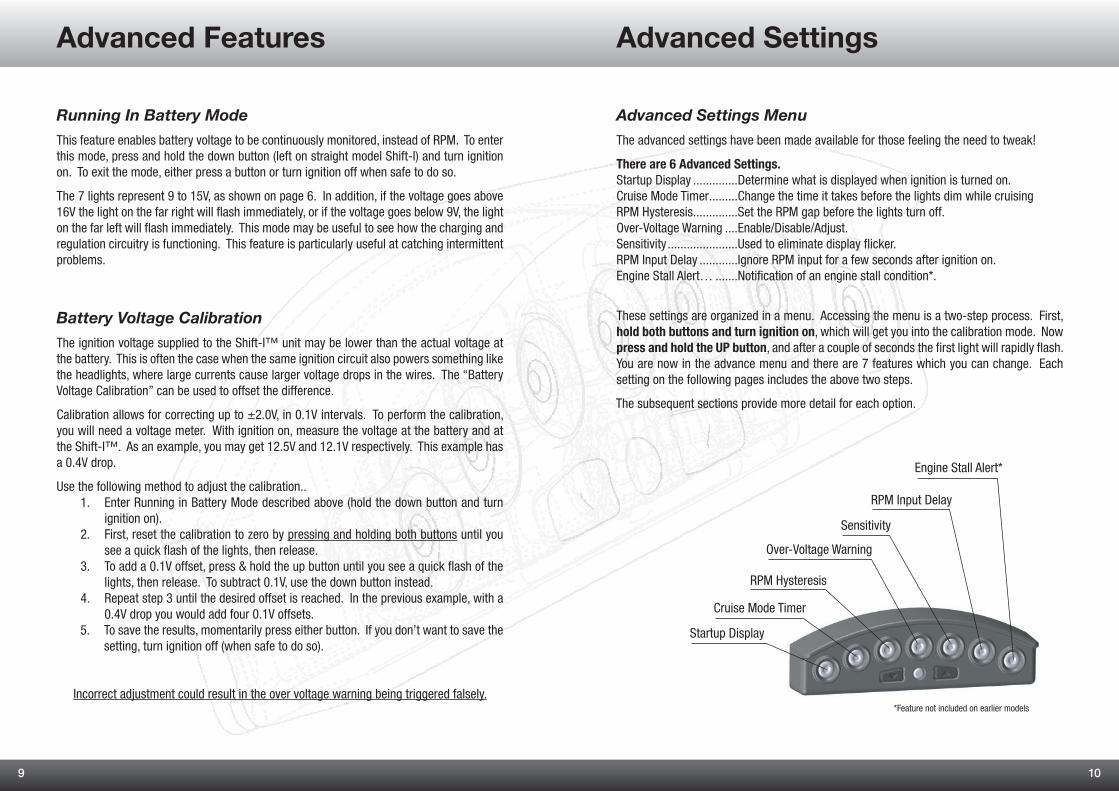
There are 6 Advanced Settings.Startup Display ..............Determine what is displayed when ignition is turned on.Cruise Mode Timer .........Change the time it takes before the lights dim while cruisingRPM Hysteresis ..............Set the RPM gap before the lights turn off.Over-Voltage Warning ....Enable/Disable/Adjust.Sensitivity ......................Used to eliminate display flicker.RPM Input Delay ............Ignore RPM input for a few seconds after ignition on.Engine Stall Alert… .......Notification of an engine stall condition*.
These settings are organized in a menu. Accessing the menu is a two-step process. First, hold both buttons and turn ignition on, which will get you into the calibration mode. Now press and hold the UP button, and after a couple of seconds the first light will rapidly flash. You are now in the advance menu and there are 7 features which you can change. Each setting on the following pages includes the above two steps.
The subsequent sections provide more detail for each option.
Sensitivity
Cruise Mode Timer
RPM Hysteresis
Over-Voltage Warning
RPM Input Delay
Engine Stall Alert*
Startup Display
*Feature not included on earlier models
Advanced Features Advanced Settings

11 12
Startup Display
1. Press both buttons and turn ignition on.2. Press and hold up button until the first light
flashes rapidly.3. Press the down button once to enter the startup
display options.
Press the up button to cycle through the options below, and press down to select the one you want.
Startup Display = Off
When ignition is turned on, the display will stay blank.
Startup Display = Shift Sequence
When ignition is turned on, the display will show the shift light sequence.
Startup Display = Shift Sequence then Battery
When ignition is turned on, the display will show the shift light sequence, then show battery voltage shortly after. When the engine first cranks, the battery voltage display will turn off ~3 seconds later.
Startup Display = Battery then Shift Sequence
When ignition is turned on, the display will show the battery voltage. When the engine first cranks, the battery voltage display will turn off 3 seconds later and then show the RPM shift sequence.
Cruise Mode Dimming
If the RPM has remained relatively steady for 1 minute, the display will automatically dim. The primary reason for including this feature is to prevent becoming accustomed to the lights (desensitized) during periods of cruising. When this feature activates, the display will slowly dim and you may not even notice it has happened. It will stay dim even with relative minor changes in RPM. However, when a significant change in RPM is detected, the display will immediately return to the original brightness.
You can adjust the time before cruise mode activates.
1. Press both buttons and turn ignition on.2. Press and hold the up button until the first light
flashes rapidly.3. Press the up button once, and the second light
should be flashing4. Press the down button to enter the Cruise Mode Timer options.
Press the up button to cycle through the options below, and press down to select the one you want.
Cruise Mode = 30 Seconds If the RPM is steady for 30 seconds, the display will dim.
Cruise Mode = 45 Seconds
Cruise Mode = 60 Seconds
Cruise Mode = 90 Seconds
Cruise Mode = 120 Seconds
Advanced Settings Advanced Settings

13 14
RPM Hysteresis
RPM hysteresis prevents flickering when the RPM is hovering around the turn on point for a light. For example, if the first light is programmed to turn on a 3,000rpm and the engine RPM is fluttering around that same point, then normally the light would flicker. With RPM hysteresis, a light may turn on at 3,000rpm, but it won’t turn off until the RPM drops a bit more, for example 2,750rpm.
1. Press both buttons and turn ignition on.2. Press and hold up button until the first light
flashes rapidly.3. Press the up button twice, and the third light
should be flashing4. Press the down button to enter the RPM Hysteresis options.
Press the up button to cycle through the options below, and press down to select the one you want.
RPM Hysteresis = Off
RPM Hysteresis = 6.25%For example, first light turns on at 1,000rpm, second light turns on at 2,000rpm, then the second light will turn off at 1937rpm
RPM Hysteresis = 12.5%
RPM Hysteresis = 25%
RPM Hysteresis = 50%
RPM Hysteresis = Auto (default)350rpm or 25%, whichever is smaller.
Over Voltage Alert
If the voltage registered at Shift-I™ exceeds 16V for more than 3 seconds, an over voltage warning is displayed. When this occurs, the display mode is overridden, and the two lights on the far right are flashed. This will still occur if the display is in the off mode. After 1 minute, this warning light will continue although the brightness will automatically dim. Normal operation is restored if the voltage falls back below 16V.
This feature will not be triggered if the voltage does not continuously remain above 16V for 3 seconds. It is also dependent on the accuracy of the “Battery Voltage Calibration”. To detect intermittent voltage fluctuations, use the “Running in Battery Mode”.
If this alert does activate, treat it seriously. When the ignition is operating above 16V, light bulbs will eventually fail, the battery will boil and there is additional risk to all electronics.
You can change the voltage alert value, or disable the feature.
1. Press both buttons and turn ignition on.2. Press and hold up button until the first light flashes rapidly.3. Press the up button three times, and the fourth light should be flashing4. Press the down button once to enter the Over Voltage Warning options.
Press the up button to cycle through the options below, and press down to select the one you want.
Over Voltage Warning = Off
Over Voltage Warning when > 15.5V
Over Voltage Warning when > 16.0V (default)
Over Voltage Warning when > 16.5V
Advanced Settings Advanced Settings
Over voltage alert!

15 16
RPM Input DelayWhen enabled, this feature will ignore the RPM input for a number of seconds after ignition is turned on. This is useful workaround for vehicles where the tacho sweeps at ignition on, and this is generated from the ECU (not a function in the instrument). Without this feature, the Shift-I assume the engine was started.
1. Press both buttons and turn ignition on.2. Press and hold up button until the first light
flashes rapidly.3. Press the up button five times, and the sixth
light should be flashing4. Press the down button to enter the RPM Input Delay options.
Press the up button to cycle through the options below, and press down to select the one you want.
No Delay (default)
3 Second Delay
4 Second Delay
5 Second Delay
6 Second Delay
Sensitivity
If you experience display flickering or the engine RPM is not being detected, then this setting should be adjusted. A lower sensitivity setting will more aggressively filter out electrical noise. A higher sensitivity setting may be needed if RPM is not being registered (due to the signal pulses being quite narrow).
1. Press both buttons and turn ignition on.2. Press and hold the up button until the first light
flashes rapidly.3. Press the up button four times, and the fifth
light should be flashing4. Press the down button once to enter the Sensitivity options.
Press the up button to cycle through the options below, and press down to select the one you want.
There are seven sensitivity setting, from minimum to maximum.
Sensitivity = Minimum
Reduce the sensitivity if the display flickers.
Sensitivity = Maximum
Increase the sensitivity if the RPM is not being detected properly.
The default setting is 4 and is appropriate for the majority of vehicles.
Lower Sensitivity SettingsTypically 3 is the lowest setting needed to filter out electrical noise. In some cases, going too low on the sensitivity may cause the RPM signal itself to be filtered out! This may only happen at the top end of the engines RPM.
Higher Sensitivity SettingsUsing a sensitivity of up to 6 is not uncommon. It’s quite rare to hear of any installation where a setting of 7 is required.
Advanced Settings Advanced Settings

17 18
Engine Stall AlertThis feature is useful for scenarios where the engine has stalled at the start line, or an excursion off track has resulted in a stalled engine. The alert gives prompt stall indication in the heat of the moment, to facilitate quick recovery.
1. Press both buttons and turn ignition on.2. Press and hold up button until the first light
flashes rapidly.3. Press the up button six times, and the last light
should be flashing.4. Press the down button once to enter the Engine Stall Alert options.
Off (default)
Engine Stall Alert On
Feature not included on earlier models.
This feature is not suited to RPM connections to fuel injector outputs.No fueling during deceleration would be interpreted as a stalled engine.
Temperature Protection
If the Shift-I™ is operated in a hot environment, it will automatically protect itself by dimming the display. It will automatically re-enable when the temperature is reduced. This is for protection only, and under normal operation this would never be observed.
System Reset
Performing a system reset will safely restore ALL factory default settings. To perform the reset, turn ignition off, press and keep held both buttons, turn ignition on and around four seconds later a rapid flashing sequence will acknowledge the reset is complete.
Tech Support
Ecliptech provides prompt technical support via the website www.ecliptech.com.auPlease make sure to provide accurate details, so we can provide accurate advice.
Warranty
The Shift-I units are very robust and reliable units. 24 month warranty from date of purchase is provided on manufacturing defects, which is void if the product is opened, disassembled, visibly damaged, or inappropriately used.
DISCLAIMER:
This product may not be suitable or safe for road use. The owner accepts ALL responsibility for its use and installation. The product must not be used if malfunction occurs, a suspected malfunction occurs and/or not configured correctly. If inappropriately placed, the headlights from another vehicle could cause the brightness to increase. It must not be used where it could obstruct the view of the operator or impair vision. The owner/driver must test before use in all ambient light conditions to ensure any malfunction or display mode, such as all lights on at maximum brightness, does not impair the ability to safely operate the vehicle. The button controls must not be used while operating the vehicle. The product must be appropriately fused, or connected to an existing appropriately fused circuit. This product must not be used for medical purposes.
Only use if safe to do so and at your own risk.
Advanced Settings Advanced Settings

INCLUDES:
User Manual
Installation and Quick Start Guide
Vinyl Backed Shift-I Logo Sticker.
Adhesive Mounting Pads
INSTALLATION:
Only 3 wires to connect.
Ground, Ignition and RPM!
www.ecliptech.com.au
Outstanding compatibility!5V/12V pulse or square wave RPM signals (instrument tacho signals and aftermarket ECU tacho outputs). Supports
connections to the low-voltage side of an ignition coil, wasted spark, late model coil-on-plug technology (modern vehicles) and even fuel injector outputs. No need for amplifiers or filters. It does not matter if your vehicle uses CAN bus.
Some capacitor-discharge / magneto (two strokes) and old (electrically noisy) distributors are not compatible.
Disclaimer: By using this product, you accept the following terms & conditions. This product may not be suitable or safe for road usage. The owner accepts ALL responsibility for its use & installation. The product must not be used if malfunction occurs or a suspected
malfunction occurs. If inappropriately placed, the headlights from another vehicle could cause the brightness to increase unexpectedly. It must not be used where it could obstruct, hinder or impair the view of the operator. Only use if safe to do so and at your own risk.
24 month warranty from date of purchase.