Embed Size (px)
Citation preview

USER MANUAL
FOR
HYDRAULIC FOLDING CRANE
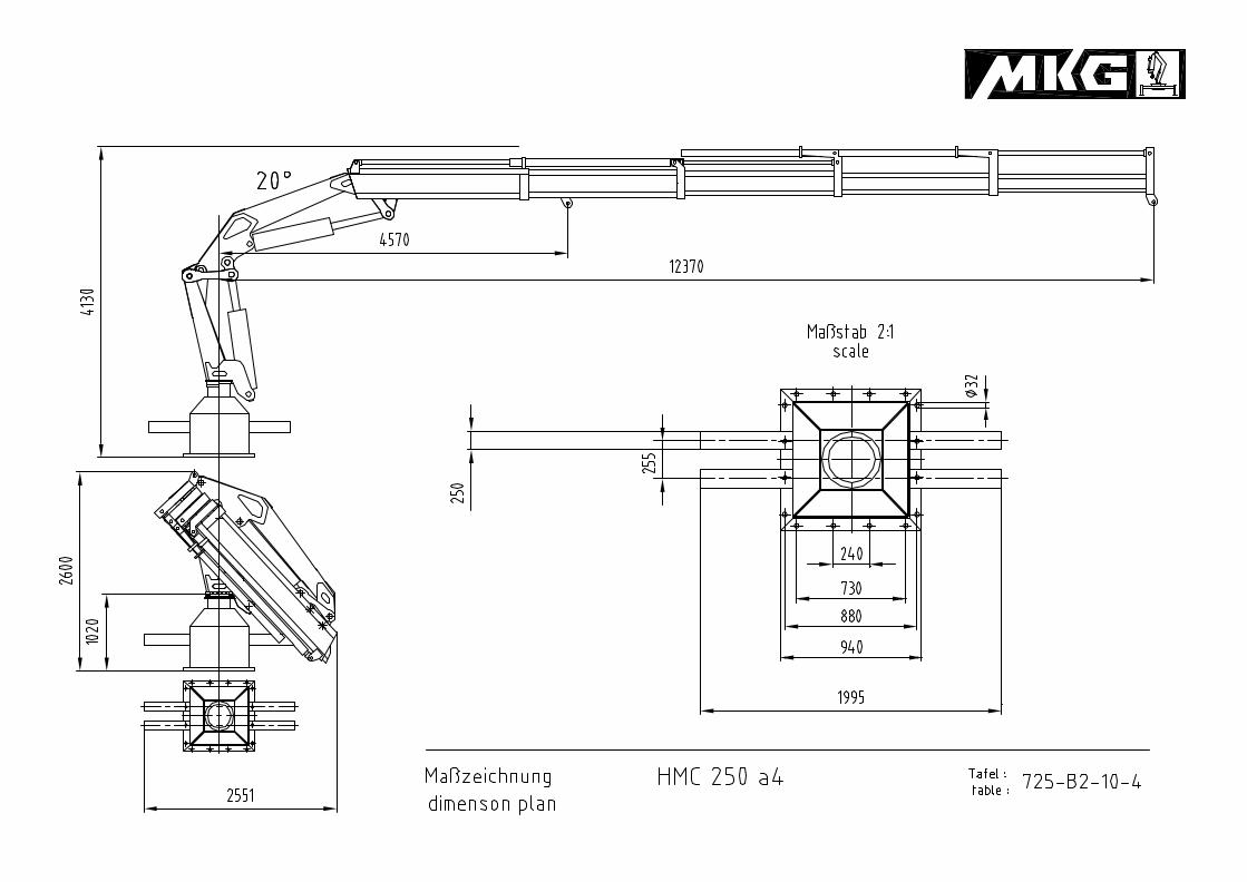
HMC 250 a4.
Postboks 30, N-4097 Sola Skvadronveien 24, N-4050 Sola
Tlf. +47 51 64 81 50 - Fax +47 51 65 76 06 E-mail: [email protected]
www.kl-offshore.no
K.LUND Offshore as
Table of contents
Preface page 1.1
Chapter 1 Accident prevention page 1.2
directions for prevention of accidents page 1.3
distances to power transmission line page 1.4
directions to product liability page 1.5
Chapter 2 Description of cranestructuredetails page 2.1-2.4
Chapter 3 Control units page 3.1
Chapter 4 Operation page 4.1
safety devices page 4.3
Chapter 5 Maintenance of cranedirections of maintenance page 5.1
maintenance and lubrication points page 5.2
lubricants page 5.3-5.5
Chapter 6 Failures and their causes page 6.1
electric symbols
Mounting instruction
K.LUND Offshore as
Preface
Your crane represents a high investment and should only be operated by trained personal to ensurea trouble-free operation at all times.
This manual contains directions in regards to the performance of the crane as well as safety atwork, correct operation and maintenance. You shall receive the best performance of your crane ifyou follow these instructions carefully.
All descriptions and illustrations are without any obligation and we reserve the right to alter oramend any data or illustration without further notice.This manual is considered for your particular crane only and will not be changed and/ocextended incase of any technical modification on this model.
ICEl ... _
1.1
K.LUND Offshore as
Chapter 1 Accident prevention
This operation manual should have been studied carefully before starting to operate the crane.
The crane operator must be acquainted with al controls of the crane as well as all functions andsafety devices.
Any {lrecaution sticks must be l?laced at well sighted locations at the crane. The national rules forprevention of accidents must be followed strictly.
Attachments: winch etc.
When crane is equipped with an attachment then the operation manual ofthe particularmanufacturer is valid.
1.2
K.LUND Offshore as
Directions for preventation of accidents!
ATTENTION!
It is strictly forbidden to stay within the slewing range of the crane, regardless whether thecrane is slewing with or without load. Prohibitive fences should be arranged to preventanybody to enter the slewing range of the crane.
Bulk goods may only be handled by the crane if secured by nets or any other suitable means ofprotection.
Bulk goods handled by fork lift attachment on the crane hook should be secured very carefullyand may only be off-loaded after the crane has come to a complete stop.
ATTENTION!
Never use any damaged slings or ropes to secure the load as this may lead to serious accidents.
ATTENTION!
It is necessary to switch off the hydraulic pump. Otherwise an excessive amount of oil willbuild-up a high pressure by too high motor speeds.
ATTENTION!
The loading capacity is not allowed to be increased by any measures as for instance thehanging up and subsequent release ofbad measurable loads. The crane vehicle could tilt overor unusual uncontrolled movements and deformations can be appear.
ATTENTION!
In case of damaged seals at overpressure valves and/or overload protection devices onlyauthorised persons may start the crane after having set the correct pressures.
The crane operator signs responsible for untouched seals on the saftey systems ofthe crane.
1.3
K.LUND Offshore as
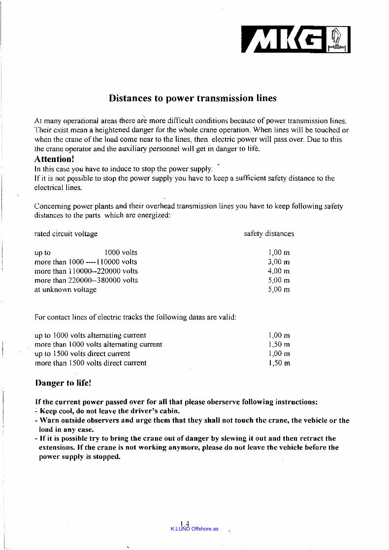
Distances to power transmission lines
At many operational areas there are more difficult conditions because of power transmission lines.Their exist mean a heightened danger for the whole crane operation. When lines will be touched orwhen the crane of the load come near to the lines, then electric power will pass over. Due to thisthe crane operator and the auxiliary personnel will get in danger to lite.
Attention!In this case you have to induce to stop the power supply.If it is not pQssible to stop the power supply you have to keep a sut1icient safety distance to theelectrical lines.
Concerning power plants and their overhead transmission lines you have to keep following safetydistances to the parts which are energized:
rated circuit voltage
up to 1000 voltsmore than 1000 ----110000 voltsmore than 110000--220000 voltsmore than 220000--380000 voltsat unknown voltage
For contact lines of electric tracks the following datas are valid:
up to 1000 volts alternating currentmore than 1000 volts alternating currentup to 1500 volts direct currentmore than 1500 volts direct current
Danger to life!
safety distances
1,00 m3,00 m
4,00 m5,00 m
5,00 m
1,00 m1,50m1,00 m1,50 m
If the current power passed over for all that please oberserve following instructions:- Keep cool, do not leave the driver's cabin.- Warn outside observers and urge them that they shall not touch the crane, the vehicle or the
load in any case.- If it is possible try to bring the crane out of danger by slewing it out and then retract the
extensions. If the crane is not working anymore, please do not leave the vehicle before thepower supply is stopped.
1.4
K.LUND Offshore as
1
Directions to product liability
In regard to the liability of a manufacturer for his products we like to point out:
Every manufacturer is liable for his product.
MKG Maschinen- und Kranbau GmbH excludes any liability for damages caused by subsequentmodifications of their product and/or unauthorised use of components supplied by othermanufacturers which have not been approved by MKG.
MKG is not responsible for damages caused by incorrect installation of their cranes includingunsuitable foundations and/or fixing materials. Any claims must be rejected in case the,generalrules of international engineering standard have not been followed.
1.5
A-A ( 1 : 20 )
B-B ( 1 : 10 )
1
1
2
2
3
3
4
4
5
5
6
6
A A
B B
C C
D D
Gewicht:
963,51 kg
Werkstoff:
Norm:
-
Zeichnungs-Nr.:
Maßstab:1:20
Rahmen mit U-bau HMC 250
-
Artikel-Nr. :
A3
Blatt
Witmer
04.06.2008
Schutzvermerk nach ISO 16016 beachten!
Allgemein-
toleranzen:
ISO 2768-mK
Name
Gezeichnet
MMMMKKKKGGGG MMMMaaaasssscccchhhhiiiinnnneeeennnn---- uuuunnnndddd KKKKrrrraaaannnnbbbbaaaauuuu GGGGmmmmbbbbHHHHDDDDaaaaiiiimmmmlllleeeerrrr ---- BBBBeeeennnnzzzz ---- SSSSttttrrrraaaaßßßßeeee 6666
DDDD---- 44449999666666661111 GGGGaaaarrrrrrrreeeellll
Kontrolliert
Norm
Datum
NameDatumÄnderungenStatus
DIN/EN -
ENG-003656.iam
A
A
B B
140
40
0
Unterbau
105
0
80
160
190
0
1400
160
180
0
120
39
2
1 21
2
860
260888
888
n32
828
1010
K.LUND Offshore as
Chapter 2
03
Description of components
04
01,02
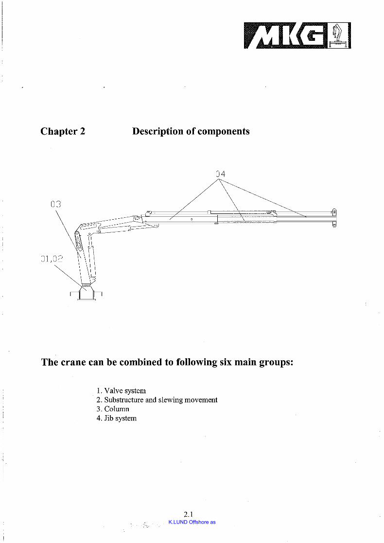
The crane can be combined to following six main groups:
1. Valve system2. Substructure and slewing movement3. Colunm4. Jib system
2.1
K.LUND Offshore as
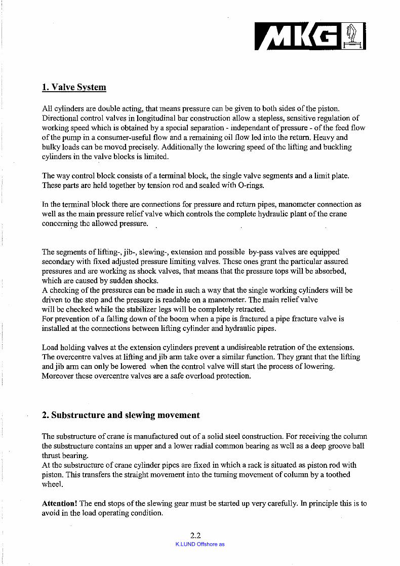
1. Valve System
All cylinders are double acting, that means pressure can be given to both sides of the piston.Directional control valves in longitudinal bar construction allow a stepless, sensitive regulation ofworking speed which is obtained by a special separation - independant ofpressure - of the feed flowofthe pump in a consumer-useful flow and a remaining oil flow led into the return. Heavy andbulky loads can be moved precisely. Additionally the lowering speed ofthe lifting and bucklingcylinders in the valve blocks is limited.
The way control block consists of a terminal block, the single valve segments and a limit plate.These parts are held together by tension rod and sealed with O-rings.
In the terminal block there are connections for pressure and return pipes, manometer connection aswell as the main pressure reliefvalve which controls the complete hydraulic plant of the craneconcemi1!g the allowed pressure. .
The segments oflifting-, jib-, slewing-, extension and possible by-pass valves are equippedsecondary with fixed adjusted pressure limiting valves. These ones grant the particular assuredpressures and are working as shock valves, that means that the pressure tops will be absorbed,which are caused by sudden shocks.A checking of the pressures can be made in such a way that the single working cylinders will bedriven to the step and the pressure is readable on a manometer. The main relief valvewill be checked while the stabilizer legs will be completely retracted.For prevention of a falling down ofthe boom when a pipe is fractured a pipe fracture valve isinstalled at the connections between lifting cylinder and hydraulic pipes.
Load holding valves at the extension cylinders prevent a undisireable retration of the extensions.The overcentre valves at lifting and jib arm take over a similar function. They grant that the liftingand jib arm can only be lowered when the control valve will start the process oflowering.Moreover these overcentre valves are a safe overload protection.
2. Substructure and slewing movement
The substructure of crane is manufactured out of a solid steel construction. For receiving the columnthe substructure contains an upper and a lower radial common bearing as well as a deep groove ballthrust bearing.At the substructure of crane cylinder pipes are fixed in which a rack is situated as piston rod withpiston. This transfers the straight movement into the turning movement of column by a toothedwheel.
Attention! The end stops of the slewing gear must be started up very carefully. In principle this is toavoid in the load operating condition.
2.2
K.LUND Offshore as
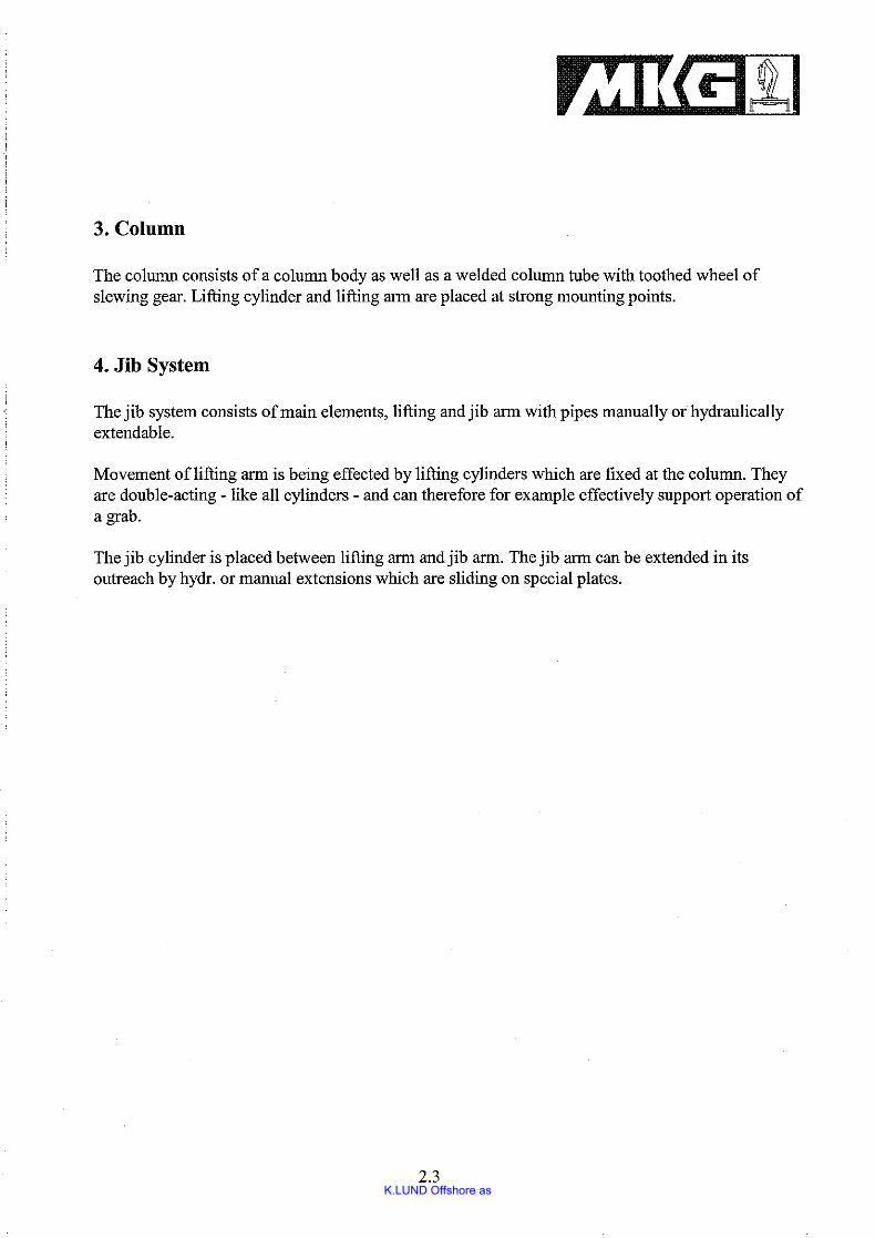
3. Column
The column consists of a column body as well as a welded column tube with toothed wheel ofslewing gear. Lifting cylinder and lifting arm are placed at strong mounting points.
4. Jib System
The jib system consists ofmain elements, lifting and jib arm with pipes manually or hydraulicallyextendable.
Movement oflifting arm is being effected by lifting cylinders which are fixed at the column. Theyare double-acting - like all cylinders - and can therefore for example effectively support operation ofa grab.
The jib cylinder is placed between lifting arm and jib arm. The jib arm can be extended in itsoutreach by hydro or manual extensions which are sliding on special plates.
2.3

K.LUND Offshore as
8. Operation of Rope Winch
The rope always has to be unspooled so far that it will not be damaged during the extension of thehydro extensions.
a) Intennediate rolls have to be mounted at manual extensions
b) Jerky control movements without any load have to be avoided (loops fonnation)
c) The indicated load capacity datas of the manual extensions have to be kept strictly
d) When crane is in operation the vehicle has to be stabilized absolutely horizontal
e) Ifpossible the rope should be reeled up under load
f) The rope has to be reeled up completey new every 4 weeks
g) Rope, rope hook and fastenings have to be checked or ifnecessary renewed regularly
h) The oil level of the winch has to be checked weekly
During lifting the load you have to pay attention that the pull is vertical (angular pull).
2.4
K.LUND Offshore as
Chapter 3 Control units
~dll
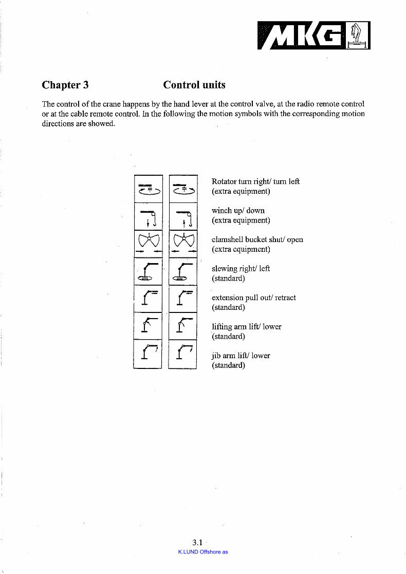
The control of the crane happens by the hand lever at the control valve, at the radio remote controlor at the cable remote control. In the following the motion symbols with the corresponding motiondirections are showed.
~~ :::>
71W- -£"[-
Fr
c¥~
0W- - ..
£"[-
Fr
Rotator tum right! tum left(extra eqnipment)
winch up/ down(extra equipment)
clamshell bucket shut! open(extra equipment)
slewing right! left(standard)
extension pull out/ retract(standard)
lifting arm lift! lower(standard)
jib arm lift! lower(standard)
3.1
K.LUND Offshore as
Safety Devices
MKG-cranes are equipped in series with the following safety devices:
Overload protection
According to § 24 the accident prevention rule "outrigger cranes" (BVG D6), overload protectionfor all cranes are necessary. In general, test books are to be made for the named cranes.
The system of the overload protection proceeds on the assumption that the pressure in the liftingcylinder will increase inadmissibly when the load moment is too high. The overload systemcontrolled by a sequential valve, blocks all functions, which increase the load moment, ifpressuregets to a certain limit of the system.
1. Pulling out of extension cylinder
2. Retraction and pulling out ofjib cylinder
This arrangement prevents that the system is overloaded and that the load decrease withoutinfluence, i. e. the crane is overloaded and the pressure relief valves react due to a pressure which istoo high.
Emergency stop on the control elements:
Press immediately emergency stop, if there are uncontrolled movements or dangeroussituations!Reactivate the crane by pulling and clicking the emergency stop into the upper position. By thismeans the electric plant will be switched on, the emergency valve will close and the hydraulicsystem will be supplied with pressure.
Attention! Cranes, which are equipped with radio remote control, the key button is to be setinto the Zero-Position!
4. 1
K.LUND Offshore as
Chapter 4 Putting into Operation
In order to start operation of crane you have to act as follows:
1. Before starting auxiliary drive the parking brake has to be set; when working at slopes ablock has to be placed under wheels.
2. Start auxiliary drive for hydraulic pump and increase speed ofengine to rotations which arenecessary for the pump.
3. Put control valve oflifting cylinder to position "Lifting" and extend lifting arm completely.
4. Put control valve ofextension cylinder to position "Pulling out" and ascend extensionapprox. 200 mm in order to unlock buckling arm.
5. After that pull out jib cylinders in order to bring the buckling arm to the desired position.
6. Pull out the extension to the desired working position.
7. If the crane is equipped with an additional jib and winch you have to proceed as describedinitm 1 t05.
4.1
K.LUND Offshore as
Chapter 4 Putting into Operation
Put the crane into operation, as follows:
1. Put the control valve of the lifting cylinder in the following position "lifting" and extend thelifting arm to the top.
2. Extend extensions into working position.
Folding of the crane into transport position
Before you fold the crane into transport position, switch off the pump and process in reverse order.The remaining overpressure in the hydraulic system can be let out by movement of valve operation.
Safety Devices
MKG-cranes are equipped in series with the following safety devices:
Overload protection
The system of the overload protection proceeds on the assumption that the pressure in the liftingcylinder will increase inadmissibly when the load moment is too high. The overload systemcontrolled by a sequential valve, blocks all functions, which increase the load moment, ifpressuregets to a certain limit ofthe system.
1. Pulling out of extension cylinder
2. Retraction and pulling out ofjib cylinder
This arrangement prevents that the system is overloaded and that the load decrease withoutinfluence, i. e. the crane is overloaded and the pressure relief valves react due to a pressure which istoo high.
4.1
K.LUND Offshore as
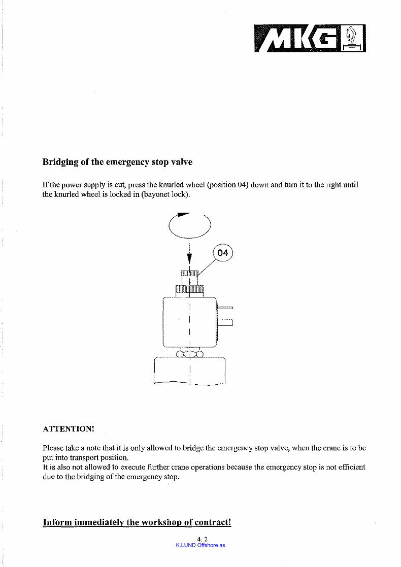
Bridging of the emergency stop valve
If the power supply is cut, press the knurled wheel (position 04) down and tum it to the right untilthe knurled wheel is locked in (bayonet lock).
6
ATTENTION!
Please take a note that it is only allowed to bridge the emergency stop valve, when the crane is to beput into transport position.It is also not allowed to execute further crane operations because the emergency stop is not efficientdue to the bridging ofthe emergency stop.
Inform immediately the workshop of contract!
4.2
K.LUND Offshore as
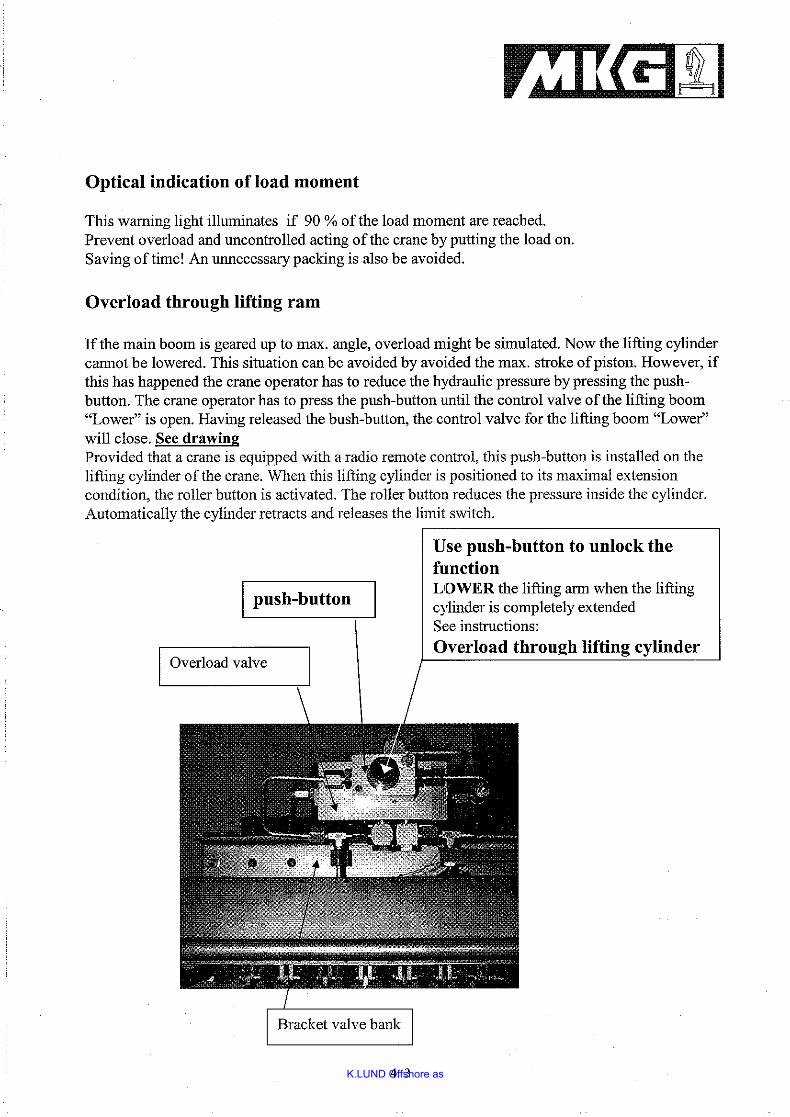
rzlliflllOptical indication of load moment
This warning light illuminates if 90 % of the load moment are reached.Prevent overload and uncontrolled acting of the crane by putting the load on.Saving oftime! An unnecessary packing is also be avoided.
Overload through lifting ram
If the main boom is geared up to max. angle, overload might be simulated. Now the lifting cylindercannot be lowered. This situation can be avoided by avoided the max. stroke ofpiston. However, ifthis has happened the crane operator has to reduce the hydraulic pressure by pressing the pushbutton. The crane operator has to press the push-button until the control valve of the lifting boom"Lower" is open. Having released the bush-button, the control valve for the lifting boom "Lower"will close. See drawingProvided that a crane is equipped with a radio remote control, this push-button is installed on thelifting cylinder of the crane. When this lifting cylinder is positioned to its maximal extensioncondition, the roller button is activated. The roller button reduces the pressure inside the cylinder.Automatically the cylinder retracts and releases the limit switch.
I push-button
I Overload valve
Bracket valve bank
4. 3
Use push-button to unlock thefunctionLOWER the lifting arm when the liftingcylinder is completely extendedSee instructions:
Overload throu~h lifting cylinder
K.LUND Offshore as
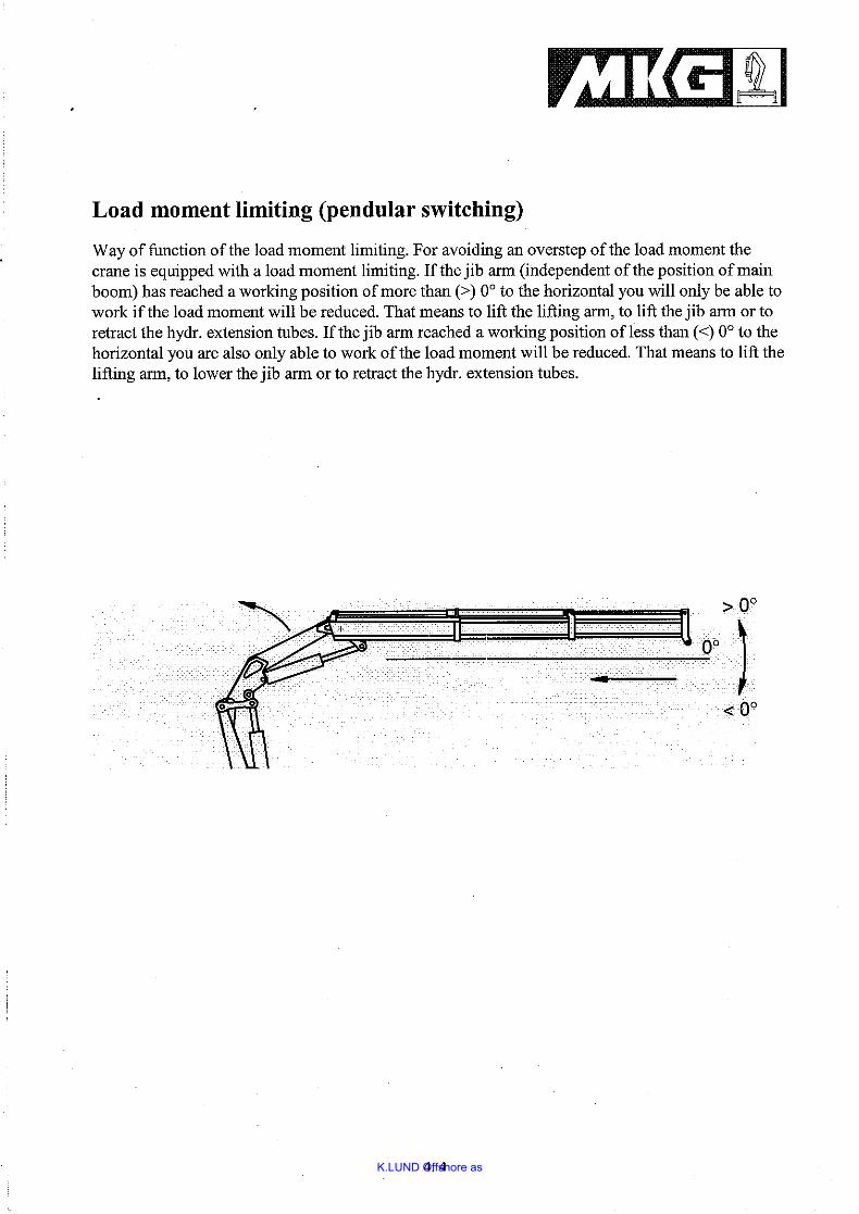
Load moment limiting (pendnlar switching)
Way of function of the load moment limiting. For avoiding an overstep ofthe load moment thecrane is equipped with a load moment limiting. If the jib arm (independent ofthe position of mainboom) has reached a working position ofmore than (» 0° to the horizontal you will only be able towork if the load moment will be reduced. That means to lift the lifting arm, to lift the jib arm or toretract the hydro extension tubes. lithe jib arm reached a working position ofless than «) 0° to thehorizontal you are also only able to work of the load moment will be reduced. That means to lift thelifting arm, to lower the jib arm or to retract the hydro extension tubes.
)
4. 4

K.LUND Offshore as
Load holding valves
MKG-cranes are equipped with load holding valves at the rams.They are a good protection against undiserable or inadmissable drifting of the piston of a cylinder inload direction.So the risk of accidents against lowering loads is excluded and a safety working is possible.
4. 5
K.LUND Offshore as
Chapter 5 Maintenance of crane
Remarks in regard to maintenance works
Attention! Before starting any maintenance works at the crane make sure you have secured thecrane booms against unintended lowering of same. The pressure on all pipes and hoses mustbe released before starting works on the hydraulic system, i.e. shutt-offpumps, retract allhydraulic cylinders and secure same. Make sure no hydraulic oil may disappear into theground.Oil binders are to be carried along.Any damaged hoses must be replaced without delay.
Important!
A careful and conscientious maintenance of the crane guarantees trouble-free operation and anextended life-time.
5.1
K.LUND Offshore as
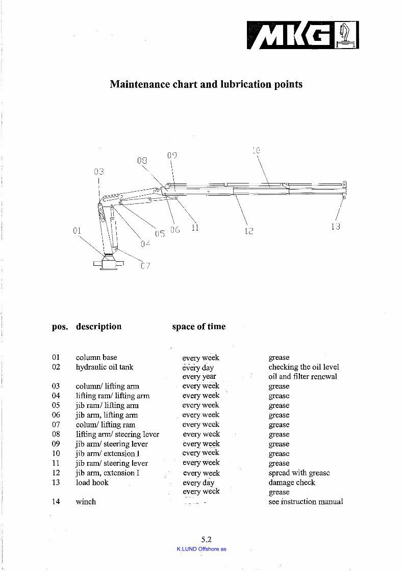
1Maintenance chart and lubrication points
09 1008
03 ~0
01 ~/
05 06 11 12 13
~,~O~07
pos. description space of time
01 column base every week grease02 hydraulic oil tank everyday checking the oil level
every year oil and filter renewal03 column! lifting ann every week grease04 lifting rami lifting arm every week grease05 jib rami lifting arm every week grease06 jib arm, lifting arm every week grease07 colum! lifting ram every week grease08 lifting arm! steering lever every week grease09 jib arm! steering lever every week grease10 jib arm! extension I every week grease11 jib rami steering lever every week grease12 jib arm, extension I every week spread with grease13 load hook everyday damage check
every week grease14 winch see instruction manual
5.2
K.LUND Offshore as
Lubricants
Specification of hydraulic oil:
The utilisation of appropriate hydraulic oil is of fundamental importance in regard to the wellfunction and life-time of a crane.High standards are set regarding frothing, viscosity, temperature gradient, point of emulsion,as well as neutral reaction toward metals and seals.
To facilitate the right choice different viscosity-classes have been introduced.
The characteristic-number corresponds to the average viscosity (mm2/s at 40DC).
We differentiate:
VG22
VG32
VG46
VG68
VGlOO
arctic conditions or extreme long supply pipes
winter condition in Central Europe
summer conditions in Central Europe or closed buildings
tropical conditions or closed buildings with high temperature
extreme hot climate
Ex works supplied oil Aviatic HLP ISO 46
Characteristics:
at 100 DC
pour point
flashing point
46 mm2/s (cST)
7,0 mm2/s (cST)
anti-corrosion agent: sufficient
5.3
K.LUND Offshore as
Maximum permissible oiltemperature for limit ofviscosity min. 10 mrn2/s (cST)
Minimum starting temperaturefor limit ofviscosity max.1500 mrn2/s (cST)
+ 80°C
- 15°C
On marine cranes a higher rust prevention degree is used.
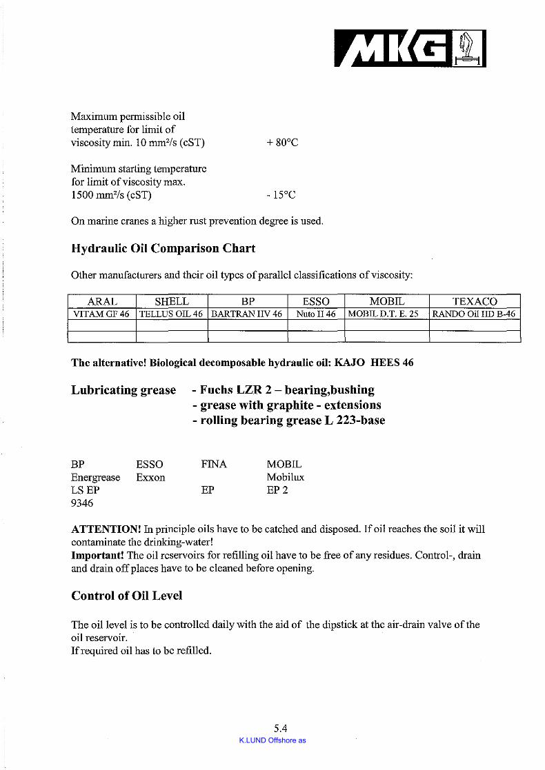
Hydraulic Oil Comparison Chart
Other manufacturers and their oil types ofparallel classifications of viscosity:
ARAL SHELL BP ESSO MOBIL TEXACOVITAMGF46 TELLUS OIL 46 BARTRAN HV 46 NutoH46 MOBIL D.T. E. 25 RANDO Oil HD B-46
The alternative! Biological decomposable hydraulic oil: KAJO HEES 46
Lubricating grease - Fuchs LZR 2 - bearing,bushing- grease with graphite - extensions- rolling bearing grease L 223-base
BPEnergreaseLSEP9346
ESSOExxon
FINA
EP
MOBILMobiluxEP2
ATTENTION! In principle oils have to be catched and disposed. If oil reaches the soil it willcontaminate the drinking-water!Important! The oil reservoirs for refilling oil have to be free of any residues. Control-, drainand drain offplaces have to be cleaned before opening.
Control of Oil Level
The oil level is to be controlled daily with the aid of the dipstick at the air-drain valve of theoil reservoir.If required oil has to be refilled.
5.4
K.LUND Offshore as
rzIDflllOil-change
Hydraulic oil becomes polluted after a certain period of time and may lead to malfunction ofthe system.
Hydraulic oil must be chauged at least every 1000 operating hours or once a yearwhatever comes first!
Remark!
A clean hydraulic oil avoids malfunction. Cleanliness is a must at all times whilst working ona hydraulic system.
Return-filters must be changed whenever the oil is changed!
High pressure filter
If the filter element of the high pressure filter is contaminated a "RED" signal appears at thecontamination indicator. In this case you have to stop working immediately to renew the filterelement.
5.5
K.LUND Offshore as
Chapter 6 Failures and their causes
1. Working movements of the truck mounted cranes are too slowly or discontinously.. control valve is contaminated (lifting resp. jib ram)
control valve is defecthydraulic pump is defect or it has to be air- reliefednot enough oil in the oil reservoiroil is unsuitable, it is foaming
2. The crane does not lift the indicated load.working pressure is too slowpiston seals are defecthelical compression ring in the pressure reliefvalve is too weak, it opens before reaching therated pressuresequence valve switches on the overload protection when reaching the load moment
3. The crane drops down under load.cylinder gasketvalves are contaminated
4. The slewing moment of the crane is too quick.the performance of the pump is too highthrottle valve is not adjusted
5. Leg ram gives way of itself.stopcocks are not closedstopcocks are leaky
6. Crane lifts more as indicated on the loading diagram.overload protection is defectvalves are contaminated
ATTENTION! If there are any failures you have to inform first of all thecontractual workshop.
6.1
K.LUND Offshore as
,. 90%
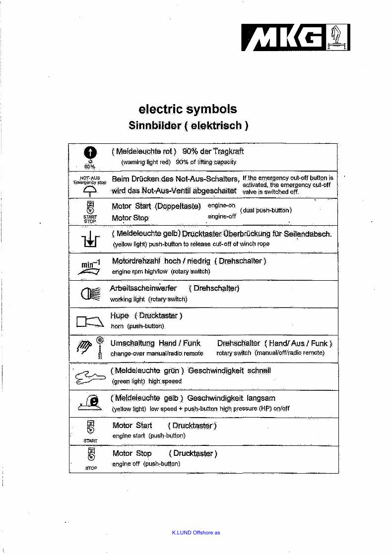
electric symbolsSinnbilder ( elektrisch )
( Meldeleuchte rot) 90% derTtagkraft(warning light red) 90% of liftingcapaciiy
1
NOT-AUS Beirn Drucken des N.ot-Aus-Schalters, If the emergency cut-off button isEmermricy stOP . .
9Wird das Not-Aus-Ventll abgeschaltet ~~:~~a~:~-:~h~~~R~nCycut'Off
~. )I,IlOtor$tart(D~ppeJtaste)engine.on (dull.lpush-buttOh)START Mot.or Stop.. engine-off'STop:
( Meldeleuchte gelb) Drucktaster Oberbruckung fUr Seiler\dabsch.(yellow light) push·button to release cut-off of winch rope •
Motordrehzahl hoch I niedrig (' Drehschalter )engine rpm high/loW (rotary switch)
Arbeitsscheinw.erfer ( Drehscniillter)working light (rotary switch)
Hupe (Drucktaster )horn (push-button)
Urnscnaltung Hand I Funkcthange-over manual/radio remote
Drenschalter (Handl Aus I Funk)rotary switch (manual/offfradio remote)
START
stoP
CMeldeJeuchte gri.ln )6eschwindigkeit schnell(green light) high speeed
(' Meldeleuc:hte gelb) Geschwindigkeit langsam(yellow light) low speed + push-button high pressure (HP) on/off
Motor Start ( Drucktas1er)engine start (push-button)
Motor Stop (' Drucktester )engine off (push-button)
K.LUND Offshore as
Mounting instruction for crane of MKG
As we assume, that skilled technicians will carry out the mounting, this instruction gives onlygeneral information.
The whole machine is to be checked by an expert or service worker. Only then you can put thecrane into operation.
The following information about technical data, diagrams and dimensions of this instructionrefer to the
Crane of MKG No.
This instruction contains specifications, sketches and points, which have to be considered inorder to guarantee excellent working.
One of the most important factors for the marine-crane mounting are to keep vibrations andnoise as low as possible.
The noise should not exceed 75 DB (A) IN a distance of 1 m (according to DIN 4412).
Comply with or reach the following points as far as possible.
Important indications which are to be considered:
1. Before mounting the crane check, fabricate or carry out first-off for the structure of thesubstructure.
2. Consider where the dead point of the crane with slewing gear of the gear rack is. Concerningthis see the sticker containing the corresponding indication on the crane foot. If you needfurther information, please contact the responsible dealer or MKG located in Garrel.
3. Use only clamping bolts which are in perfect condition. These bolts must have the prescribedstrength or quality. -(Regarding this see the technical data containing specifications)
4. All lines and flexible connections (hoses) or pumps between the crane and the hydraulicaggregate need to have the adequate diameter. Concerning this see the indications on thehydraulic plan of the manufacture.
K.LUND Offshore as
5. angled screw coupling of 90° have to be avoided
6. If you can not bend the pipes, it is better to use pipe bend of 90° instead of angled screwcoupling of 90°.
7. Use flexible bulkhead stuffing box which is to be attached by welding when tubes areassembled in bulkhead walls or similar places.
8. Fix hydraulic pipes by clamps with rubber elements instead ofplastic elements. Clamps withrubber elements reduce noise and vibrations. Distance between the clamps must be accordingto the specification ofthe clamp manufacturer.
9. With separate standing power-pack the tanlc should be installed on flexible mounts. Neverweld or screw it together with the substructure
10. The hydraulic aggregate or hydraulic tank is to be placed in that way, that a well circulation ofair is possible and the aggregate can be cooled while working. If there is sufficient circulationof air but not enough cooling, it is necessary to install a fan-type air cooling or heat cooler.Concerning this consider the normal and maximum of oil temperature stated in the manual.
11. If required by the winch manufacturer an oil filter is to be installed in the leak oil pipe fromthe winch to the tank.
12. Please take a note that filter elements placed in the return and leak oil pipe of winch (if filteris installed) are to be changed after 20 service hours or after a repair.
13. Before installation and putting into operation all screwing and lines have to be in anabsolutely clean condition Therefore, the whole system is to be cleaned by flushing. Onlyafter this the hydraulic system can be filled with hydraulic oil which has a viscosity of 46mm2/s (46 cSt) on 40°C corresponding to the ISO VO 46.
All cranes are tested carefully before they leave the factory. If the crane mounting is carried outcarefully, a perfect working with the crane should be guaranteed, If you have further questionsconcerning the installation, please do not hesitate to contact the responsible dealer or themanufacturer MKG located in Garrel.
Please keep always in mind the golden rule of hydraulic:
C Iea nlin es s - Cle anli n e s s - Clea nli n es s
02 01.03.2012 As build Mgr Tnu
01 09.08.2011 As build Tnu Bbe Kgj
Proj.rev.code Issue date Reason for issue Made by
Chk'd by
Appr. by
P.O.Number Package Title
HYDRAULIC POWER UNIT (HPU) Tag.No.(s)
4989/5190
supplier logo Stavanger department
For project use
1 2 3 4
Date
Sign.
Suppl. Doc. Number
270034-001
Project Code Area/Location System Code
Document title (must be identical to entry on SMDR)
BRUKERMANUAL
SDRL Code(s)
Project Document No.
Side 1 av 11
’
DOKUMENT NO. 270034-001
Side 2 av 11
BRUKER MANUAL
2
INNHOLD 1. INTRODUKSJON 1.1 Generelt 1.2 Personell 1.3 Grunnleggende sikkerhets regler 2. HPU Serie nr. 4989/5190
2.1 Kort Beskrivelse 2.2 Sikkerhet 2.3 Start av HPU’en 2.4 System valg og bruk 2.5 Tilkoblinger. 3 Akkumulator skid (ekstra utstyr) 3.1 Kort beskrivelse 3.2 Sikkerhet 3.3 Bruk av skiden og opplading
DOKUMENT NO. 270034-001
Side 3 av 11
BRUKER MANUAL
3
1. INTRODUKSJON 1.1 Viktig Informasjon Denne manual beskriver betjening av Hydraulisk power unit (HPU). For mer detaljert teknisk informasjon på HPU’en, referes til the Datablad HPU,
dokument nr. 270034-003 For informasjon om vedlikehold og feilsøking, henvises til Vedlikeholdsmanual , dokument nr. 270034-002 Følgende symboler er benyttet ved siden av teksten for å påkalle leserens oppmerksomhet på spesielt viktige deler av manualen.
Dette symbol indikerer viktig informasjon.
Dette symbol betyr at informasjonen omhandler sikkerhets aspekter ved en potensiell farlig situasjon.
1.2 Personell
Det er en forutsetning at HPU’en betjenes av opplærd personell. På samme vis er det et krav at vedlikeholds personell har tilsvarende opplæring nødvendig for å betjene og teste HPU’en, og at de har grunnleggende kunnskaper for å kunne analysere mulige problemer, finne årsaker til disse og foreta nødvendige korrektive tiltak.
DOKUMENT NO. 270034-001
Side 4 av 11
BRUKER MANUAL
4
1.3 Grunnleggende sikkerhets regler
• Husk å alltid frakople forsyningskabler før service og vedlikehold.
• Ved service og reparasjon på hydraulikksystemet, er det av fundamental betydning at det tas forholdsregler for å forhindre at ikke forurensninger i form av partikler eller vann trenger inn i systemet.
• Ved sveising må tilliggende områder beskyttes for sveisesprut og
slipe støv! • Sveising må utføres i henhold til godkjente prosedyrer og kontroll
rutiner. • Det er ikke tillatt å bore huller i lastbærende deler eller i hule tett
lukkede deler.
DOKUMENT NO. 270034-001
Side 5 av 11
BRUKER MANUAL
5
2. EX HPU 22 kW Utleie id. 4989/5190
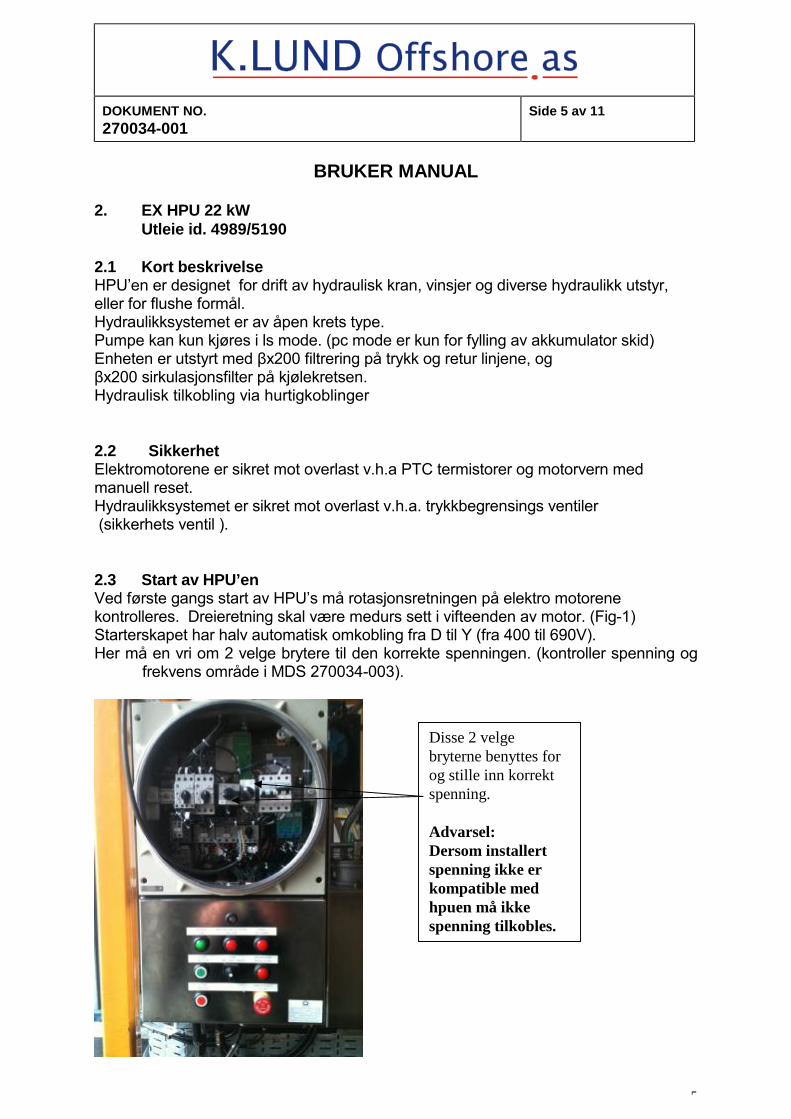
2.1 Kort beskrivelse HPU’en er designet for drift av hydraulisk kran, vinsjer og diverse hydraulikk utstyr, eller for flushe formål. Hydraulikksystemet er av åpen krets type. Pumpe kan kun kjøres i ls mode. (pc mode er kun for fylling av akkumulator skid) Enheten er utstyrt med βx200 filtrering på trykk og retur linjene, og βx200 sirkulasjonsfilter på kjølekretsen. Hydraulisk tilkobling via hurtigkoblinger 2.2 Sikkerhet Elektromotorene er sikret mot overlast v.h.a PTC termistorer og motorvern med manuell reset. Hydraulikksystemet er sikret mot overlast v.h.a. trykkbegrensings ventiler (sikkerhets ventil ). 2.3 Start av HPU’en Ved første gangs start av HPU’s må rotasjonsretningen på elektro motorene kontrolleres. Dreieretning skal være medurs sett i vifteenden av motor. (Fig-1) Starterskapet har halv automatisk omkobling fra D til Y (fra 400 til 690V). Her må en vri om 2 velge brytere til den korrekte spenningen. (kontroller spenning og
frekvens område i MDS 270034-003).
Disse 2 velge bryterne benyttes for og stille inn korrekt spenning. Advarsel: Dersom installert spenning ikke er kompatible med hpuen må ikke spenning tilkobles.
DOKUMENT NO. 270034-001
Side 6 av 11
BRUKER MANUAL
6
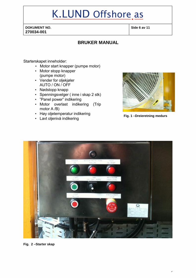
Starterskapet inneholder:
• Motor start knapper (pumpe motor) • Motor stopp knapper
(pumpe motor) • Vender for oljekjøler
AUTO / ON / OFF • Nødstopp knapp • Spenningsvelger ( inne i skap 2 stk) • ”Panel power” indikering • Motor overlast indikering (Trip
motor A /B) • Høy oljetemperatur indikering • Lavt oljenivå indikering
Fig. 1 –Dreieretning medurs
Fig. 2 –Starter skap
DOKUMENT NO. 270034-001
Side 7 av 11
BRUKER MANUAL
7
Før start skal følgende kontroller utføres: • Hydraulikkolje nivå • Kontroller at kjøleluft rister ikke er tildekket • Kontroller den aktuelle nettspenningen. • Nødstopp knapp må være ute
2.4 Systemvalg og bruk Velg system med ”mode” ventilen på instrumentpanelet
• For LS system (lastavkjenning), sett ventilen i pos. ”LS on” VIKTIG Denne modusen skal brukes når kranen kjøres. Bilde
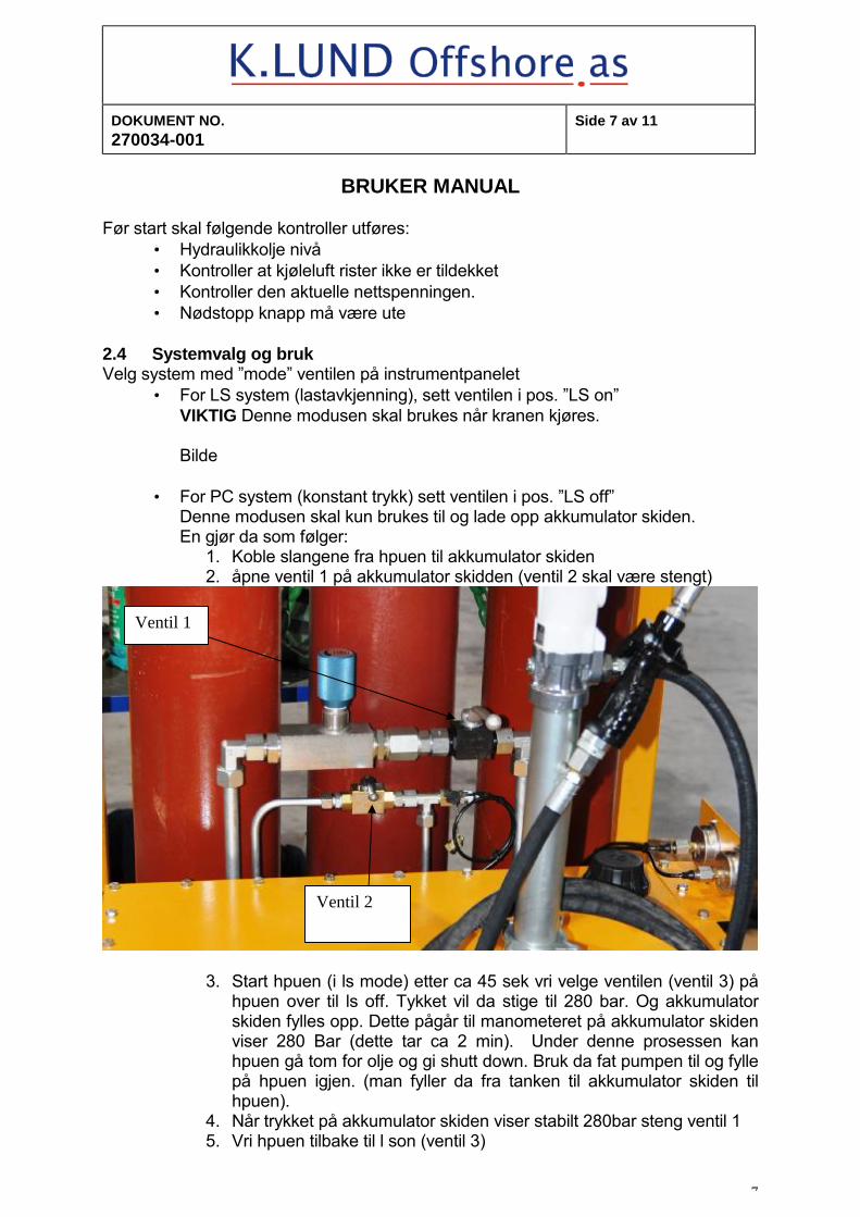
• For PC system (konstant trykk) sett ventilen i pos. ”LS off” Denne modusen skal kun brukes til og lade opp akkumulator skiden. En gjør da som følger:
1. Koble slangene fra hpuen til akkumulator skiden 2. åpne ventil 1 på akkumulator skidden (ventil 2 skal være stengt)
3. Start hpuen (i ls mode) etter ca 45 sek vri velge ventilen (ventil 3) på hpuen over til ls off. Tykket vil da stige til 280 bar. Og akkumulator skiden fylles opp. Dette pågår til manometeret på akkumulator skiden viser 280 Bar (dette tar ca 2 min). Under denne prosessen kan hpuen gå tom for olje og gi shutt down. Bruk da fat pumpen til og fylle på hpuen igjen. (man fyller da fra tanken til akkumulator skiden til hpuen).
4. Når trykket på akkumulator skiden viser stabilt 280bar steng ventil 1 5. Vri hpuen tilbake til l son (ventil 3)
Ventil 1
Ventil 2
DOKUMENT NO. 270034-001
Side 8 av 11
BRUKER MANUAL
8
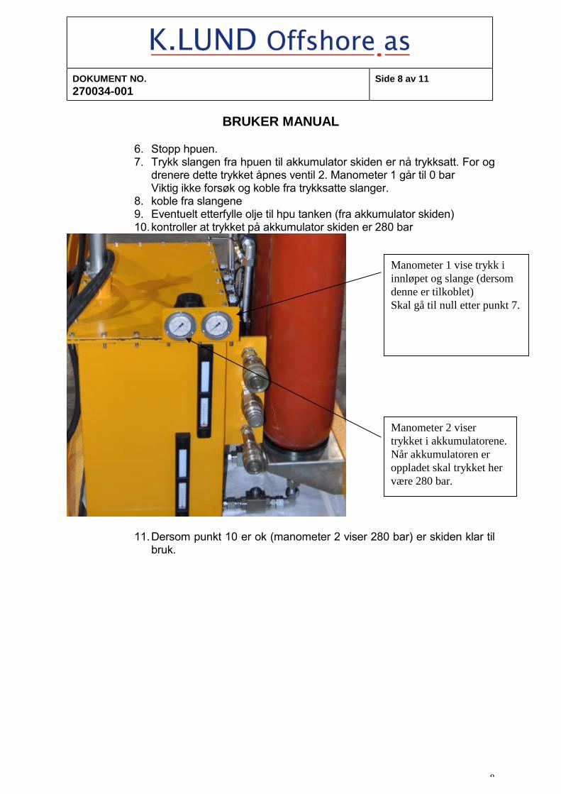
6. Stopp hpuen. 7. Trykk slangen fra hpuen til akkumulator skiden er nå trykksatt. For og
drenere dette trykket åpnes ventil 2. Manometer 1 går til 0 bar Viktig ikke forsøk og koble fra trykksatte slanger.
8. koble fra slangene 9. Eventuelt etterfylle olje til hpu tanken (fra akkumulator skiden) 10. kontroller at trykket på akkumulator skiden er 280 bar
11. Dersom punkt 10 er ok (manometer 2 viser 280 bar) er skiden klar til bruk.
Manometer 1 vise trykk i innløpet og slange (dersom denne er tilkoblet) Skal gå til null etter punkt 7.
Manometer 2 viser trykket i akkumulatorene. Når akkumulatoren er oppladet skal trykket her være 280 bar.
DOKUMENT NO. 270034-001
Side 9 av 11
BRUKER MANUAL
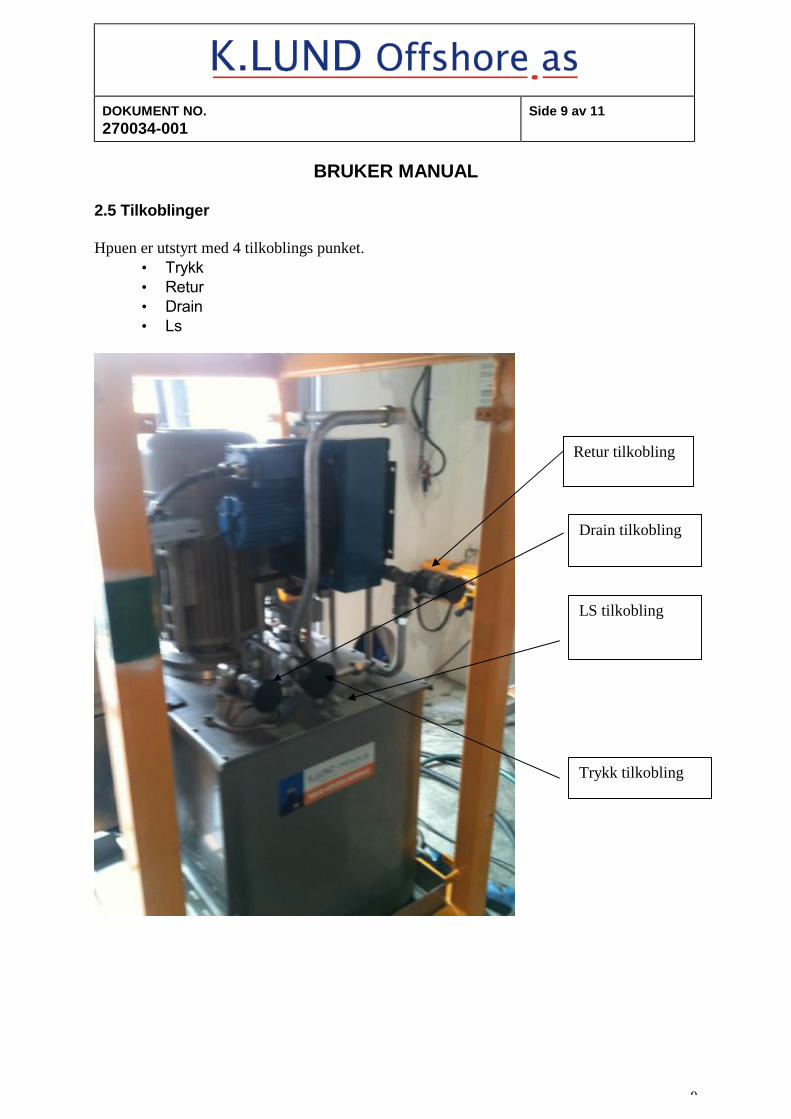
9
2.5 Tilkoblinger Hpuen er utstyrt med 4 tilkoblings punket.
• Trykk • Retur • Drain • Ls
Trykk tilkobling
Retur tilkobling
Drain tilkobling
LS tilkobling
DOKUMENT NO. 270034-001
Side 10 av 11
BRUKER MANUAL
10
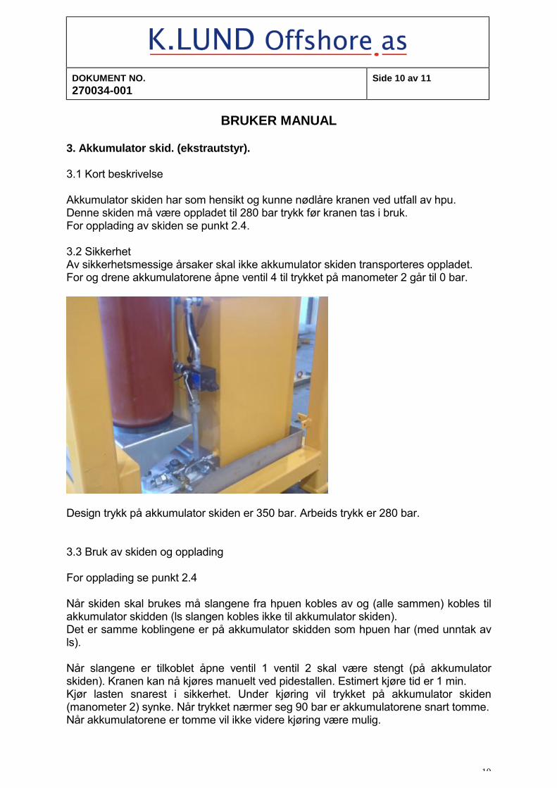
3. Akkumulator skid. (ekstrautstyr). 3.1 Kort beskrivelse Akkumulator skiden har som hensikt og kunne nødlåre kranen ved utfall av hpu. Denne skiden må være oppladet til 280 bar trykk før kranen tas i bruk. For opplading av skiden se punkt 2.4. 3.2 Sikkerhet Av sikkerhetsmessige årsaker skal ikke akkumulator skiden transporteres oppladet. For og drene akkumulatorene åpne ventil 4 til trykket på manometer 2 går til 0 bar.
Design trykk på akkumulator skiden er 350 bar. Arbeids trykk er 280 bar. 3.3 Bruk av skiden og opplading For opplading se punkt 2.4 Når skiden skal brukes må slangene fra hpuen kobles av og (alle sammen) kobles til akkumulator skidden (ls slangen kobles ikke til akkumulator skiden). Det er samme koblingene er på akkumulator skidden som hpuen har (med unntak av ls). Når slangene er tilkoblet åpne ventil 1 ventil 2 skal være stengt (på akkumulator skiden). Kranen kan nå kjøres manuelt ved pidestallen. Estimert kjøre tid er 1 min. Kjør lasten snarest i sikkerhet. Under kjøring vil trykket på akkumulator skiden (manometer 2) synke. Når trykket nærmer seg 90 bar er akkumulatorene snart tomme. Når akkumulatorene er tomme vil ikke videre kjøring være mulig.
DOKUMENT NO. 270034-001
Side 11 av 11
BRUKER MANUAL
11
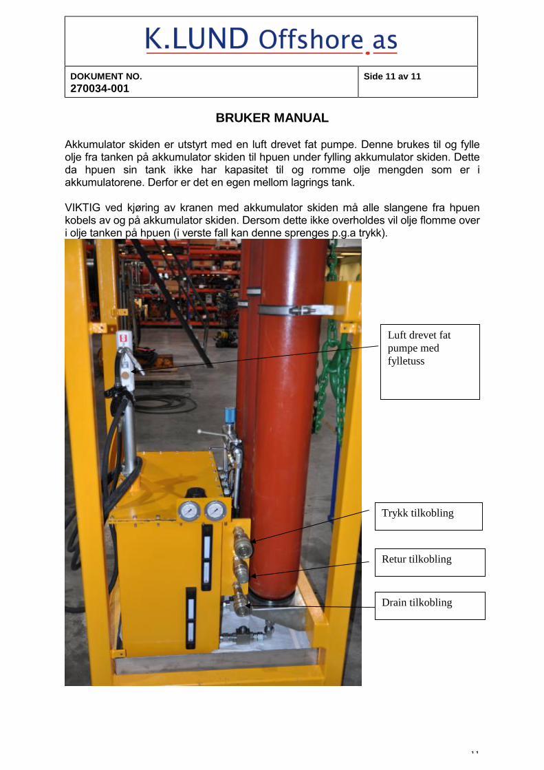
Akkumulator skiden er utstyrt med en luft drevet fat pumpe. Denne brukes til og fylle olje fra tanken på akkumulator skiden til hpuen under fylling akkumulator skiden. Dette da hpuen sin tank ikke har kapasitet til og romme olje mengden som er i akkumulatorene. Derfor er det en egen mellom lagrings tank. VIKTIG ved kjøring av kranen med akkumulator skiden må alle slangene fra hpuen kobels av og på akkumulator skiden. Dersom dette ikke overholdes vil olje flomme over i olje tanken på hpuen (i verste fall kan denne sprenges p.g.a trykk).
Trykk tilkobling
Retur tilkobling
Drain tilkobling
Luft drevet fat pumpe med fylletuss
02 01.03.2012 As buildt Mgr Tnu
01 14.08.2011 As buildt tnu bbe
kgj
Proj.rev.code Issue date Reason for issue Made by
Chk'd by
Appr. by
P.O.Number Package Title
HYDRAULIC POWER UNIT (HPU)
Tag.No.(s) 4989/5190
supplier logo Stavanger department
For project use
1 2 3 4
Date
Sign.
Suppl. Doc. Number
270034-002
Project Code Area/Location System Code
Document title (must be identical to entry on SMDR)
VEDLIKEHOLDSMANUAL FOR EX HPU 22kw
SDRL Code(s)
Project Document No.
Side 1 of 10
DOKUMENT Nr. 270034-002
SIDE 2 AV 10
VEDLIKEHOLDSMANUAL
2
INNHOLDSFORTEGNELSE 1. INTRODUKSJON
1.1 Viktig informasjon 1.2 Generelt 1.3 Vedlikeholds filosofi 1.4 Sikkerhets hensyn
2. VEDLIKEHOLD SJEKK LISTE
2.1 Generelt 2.2 Vedlikeholds interval 2.3 Vedlikeholds koder 2.4 Liste over smøremidler 2.5 Vedlikehold sjekk liste 2.6 Orientering 2.7 Preservering 2.8 Depreservering 2.9 Justerings punkter
3. ELEKTRISK 3.1 Vedlikehold
DOKUMENT Nr. 270034-002
SIDE 3 AV 10
VEDLIKEHOLDSMANUAL
3
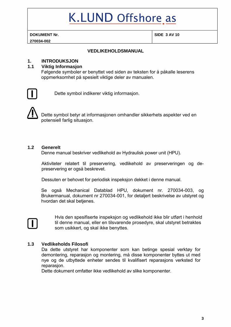
1. INTRODUKSJON 1.1 Viktig Informasjon
Følgende symboler er benyttet ved siden av teksten for å påkalle leserens oppmerksomhet på spesielt viktige deler av manualen.
Dette symbol indikerer viktig informasjon.
Dette symbol betyr at informasjonen omhandler sikkerhets aspekter ved en potensiell farlig situasjon.
1.2 Generelt Denne manual beskriver vedlikehold av Hydraulisk power unit (HPU). Aktiviteter relatert til preservering, vedlikehold av preserveringen og de-preservering er også beskrevet. Dessuten er behovet for periodisk inspeksjon dekket i denne manual. Se også Mechanical Datablad HPU, dokument nr. 270034-003, og Brukermanual, dokument nr 270034-001, for detaljert beskrivelse av utstyret og hvordan det skal betjenes.
Hvis den spesifiserte inspeksjon og vedlikehold ikke blir utført i henhold til denne manual, eller en tilsvarende prosedyre, skal utstyret betraktes som usikkert, og skal ikke benyttes.
1.3 Vedlikeholds Filosofi
Da dette utstyret har komponenter som kan betinge spesial verktøy for demontering, reparasjon og montering, må disse komponenter byttes ut med nye og de utbyttede enheter sendes til kvalifisert reparasjons verksted for reparasjon. Dette dokument omfatter ikke vedlikehold av slike komponenter.
DOKUMENT Nr. 270034-002
SIDE 4 AV 10
VEDLIKEHOLDSMANUAL
4
1.4 Sikkerhets hensyn Spesiell oppmerksomhet må utvises når det skal gjøres service på
utstyret:
• Koble alltid fra strømtilførselen før det gjøres arbeider på HPU’en. • Ved service og reparasjon på det hydrauliske system, er det av
fundamental betydning at det tas forholdsregler for å forhindre at ikke forurensninger i form av partikler eller vann trenger inn i systemet.
• Ved sveising må tilliggende områder beskyttes for sveisesprut og
slipe støv!
• Sveising må utføres i henhold til godkjente prosedyrer og kontroll rutiner.
• Det er ikke tillatt å bore huller i lastbærende deler eller i hule tett
lukkede deler.
DOKUMENT Nr. 270034-002
SIDE 5 AV 10
VEDLIKEHOLDSMANUAL
5
2. VEDLIKEHOLD SJEKK LISTE 2.1 Generelt For å lette planlegging og oppfølgning av vedlikeholdet, er det utarbeidet en
"Vedlikehold Sjekk Liste", se kapitel 2.5. Vedlikehold og reparasjon av de forskjellige komponenter er beskrevet i
vedleggene. Denne informasjon er basert på produsentenes egne dokumenter og er bare
inkludert som en hjelp til forståelse av komponentenes funksjon, og som en hjelp ved feilsøking.
2.2 Vedlikeholds Intervall Tre forskjellige vedlikeholds intervall anvendes, T1, T2, T3 and T4. T1 er daglig T2 er ukentlig T3 er hver 6 måned T4 er årlig
I tillegg kommer periodisk (årlig) inspeksjon / sertifisering av løfteramme / slings i følge gjeldende regelverk.
2.3 Vedlikeholds Koder Det er tre vedlikeholds koder identifisert med V, L(n) and M(n). V indikerer en visuell inspeksjon av for eksempel nivå eller utseende på utstyret. L(n) indikerer smøre-punkt, hvor (n) er et nummer som identifiserer type
smøremiddel som skal anvendes. Se kapitel 2.4 Liste over smøremidler.
M(n) indikerer en sjekk og justeringing av trykk på spesifisert nivå. Punkt nummereringen korresponderer med målepunktene som angitt på
tegningene. Tillatt trykk område og justeringsnivå, er også angitt under hvert punkt.
DOKUMENT Nr. 270034-002
SIDE 6 AV 10
VEDLIKEHOLDSMANUAL
6
2.4 Liste over smøremidler
Flere forskjellige smøremidler kan anvendes. Man skal imidlertid passe på IKKE Å BLANDE forskjellige fabrikat hydraulikk olje, L1!
Shell produkter anvendes av leverandør ved innledende kjøring og testing av HPU’en. Andre olje fabrikat/typer kan anvendes, forutsatt de tilsvarer eller overgår de listede spesifikasjoner.
L1 Hydraulisk olje, ca. 200 liter på HPU. Viskositet min. 12 cSt ved 75o C, max 800 cSt ved kaldstart. SHELL : Tellus T32 Q8 : Handel 32 STATOIL : HydraWay HVXA 32 YX ENERGY : RANDO HDZ 32 L2 Grease FAG : Arcanol TEMP110 SKF : LGHQ 3 MOBIL : Mobilith SHC 100 SHELL : Abida EMS 2 2.5 Vedlikeholds Sjekk Liste
På følgende sider fines sjekklister for vedlikehold av de forskjellige deler. Listen kan gjerne re-arrangeres for å passe inn i et større program, men de angitte intervall bør opprettholdes.
En logg bør etableres for dokumentasjon av alt utført vedlikehold.
Estimert tid for å utføre vedlikeholdet er eksklusive tilkomst tid:
DOKUMENT Nr. 270034-002
SIDE 7 AV 10
VEDLIKEHOLDSMANUAL
7
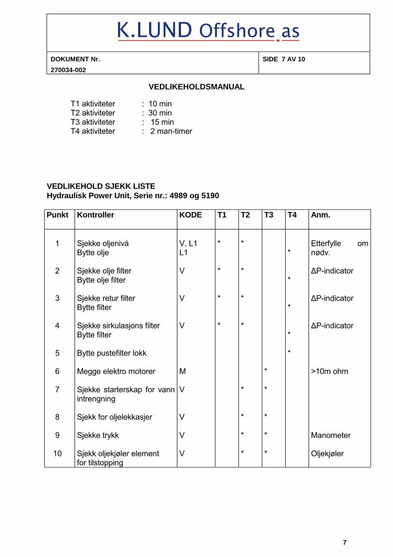
T1 aktiviteter : 10 min T2 aktiviteter : 30 min T3 aktiviteter : 15 min T4 aktiviteter : 2 man-timer VEDLIKEHOLD SJEKK LISTE Hydraulisk Power Unit, Serie nr.: 4989 og 5190 Punkt Kontroller KODE T1 T2 T3 T4 Anm.
1 2 3 4 5 6 7 8 9 10
Sjekke oljenivå Bytte olje Sjekke olje filter Bytte olje filter Sjekke retur filter Bytte filter Sjekke sirkulasjons filter Bytte filter Bytte pustefilter lokk Megge elektro motorer Sjekke starterskap for vann intrengning Sjekk for oljelekkasjer Sjekke trykk Sjekk oljekjøler element for tilstopping
V, L1 L1 V V V M V V V V
* * * *
* * * * * * * *
* * * * *
* * * * *
Etterfylle om nødv. ΔP-indicator ΔP-indicator ΔP-indicator >10m ohm Manometer Oljekjøler
DOKUMENT Nr. 270034-002
SIDE 8 AV 10
VEDLIKEHOLDSMANUAL
8
2.6 Orientering Dette er en kort forklaring av de forskjellige punkt i Vedlikeholds Sjekkliste.
Hydraulikk olje Sjekk nivå ved nivå glass.
Sjekk for mulige lekkasjer i slanger, fittings og komponenter. Oljebytte bør skje rett etter HPU’en har vært i bruk, med varm olje, for å lette
tømming. Sjekk brukt olje for forurensninger og vann innhold.
Ny olje bør fylles med en pumpe med et 10 my filter. I tilfelle en slik pumpe ikke er tilgjengelig, bruk kun rene beholdere/trakter ved påfylling av ny olje!
Ved langtids lagring skal tanken være helt full av olje.
Filter Bytte Trykkfilter
Bruk et drypp kar under filter for å redusere olje søl. Skru av filterbolle for å bytte element. Undersøk oljen I bunnen av bolle. Ved spor av forurensning, studer denne nøye. Metall partikler, stål eller bronse, indikerer slitasje på de roterende enheter. En olje prøve bør tas fra tanken og analyseres. Retur / sirkulasjon filter Skru av filterlokket og trekk elementet forsiktig opp.
Smøring av Elektrisk Motor
Elektromotorene er utstyrt med permanent smurte lager, og trenger ikke vedlikehold.
Kontroll av oljetrykk. Oljetrykket må sjekkes før HPU’en tas I bruk for å verifisere korrekt funksjon.
Hoved trykket er last avhengig og kan variere i det spesifiserte område. Når pumpene går på tomgang, skal trykket være ca. 40 bar.
Visuell kontroll Visuell kontroll av HPU utføres for å forsikre om at “alt er OK”. Hydrauliske system er utsatt for lekkasjer, og elektriske panel for vann intrengning. Det er viktig å finne og fjerne årsakene så snart som mulig.
DOKUMENT Nr. 270034-002
SIDE 9 AV 10
VEDLIKEHOLDSMANUAL
9
2.7 Preservering
Ved lagring i kaldt vær må oljekjøler alltid tømmes for vann. Bortsett fra dette trenger ikke HPU’en noe spesiell preservering når den ikke er i bruk. Ved langtids lagring må følgende utføres: • hydraulikk tanken må fylles med olje til max nivå • alle kule-ventiler skal stenges • synlige mekaniske skader skal repareres • sår eller andre skader på overflate behandling skal repareres • dekk til kjøleluft ristene for å beskytte mot vær og vind • ved langtid lagring bør elektromotorene roteres for hånd
hver 2 mnd.
2.8 Depreservering
Når utstyret tas ut fra lager skal det inspiseres grundig. Forurensninger eller fremmed partikler skal fjernes. • sjekk hydraulikkolje for inntrengning av vann • alle kule ventiler skal åpnes (untatt drenerings ventil ) • synlige mekaniske skader skal repareres • sår eller andre skader på overflate behandling skal repareres • fjerne tildekking av kjøleluft ristene
DOKUMENT Nr. 270034-002
SIDE 10 AV 10
VEDLIKEHOLDSMANUAL
10
2.9 Justerings Punkter Det hydrauliske system har justerings punkter for • hovedtrykk / trykkavskjæring • sikkerhets ventil (må ligge 20-30 barg over hovedtrykk)
VIKTIG Disse justeringene er inn tanken og skal kun justeres av fagpersonell fra K.Lund Offshroe as. Dersom dette ikke overholdes er ikke lengre atex sertifiseringen gyldig.
Vær også klar over at feilaktig justering av sikkerhets ventiler kan
forårsake skade på HPU’en og tilsluttet utstyr. Det kan også representere en fare for alle tilstedeværende i HPU området, og
ødelegger betingelsene for leverandørens garanti. 3.1 Elektrisk vedlikehold For vedlikeholdslister henviser til egne kontrollark.
• formularnr.9-12.7 (for generell elektrisk) • formularnr.9-12.11 (for atex vedlikehold)
Dersom kontrollpunktene ikke er merket med noen * (stjerner) kontrolleres disse før hver utsendelse. Kontrollpunkter: * utføres årlig Kontrollpunkter: ** utføres på det som faller først. – 1,5år eller 3000 driftstimer. Kontrollpunkter: *** utføres på det som forfaller først. – 5år eller 6000 driftstimer.