Embed Size (px)
Citation preview

User Manual
August 2013
ZEETM303D Rev. D

Trademarks Acknowledgements
Snap-on and Vantage PRO are trademarks of Snap-on Incorporated.
All other marks are trademarks or registered trademarks of their respective holders.
Copyright Information
©2013 Snap-on Incorporated
All rights reserved.
Disclaimer
The information, specifications and illustrations in this manual are based on the latest information available at the time of printing.
Snap-on reserves the right to make changes at any time without notice.
Visit our website at:
http://diagnostics.snapon.com (North America)
www1.snapon.com/diagnostics/uk (United Kingdom)
snapontools.com.au (Australia and New Zealand)
For Technical Assistance
CALL 1-800-424-7226 (North America)
CALL +44 (0) 845 601 4736 (United Kingdom)
1800 810 581 (Australia and New Zealand)
E-mail [email protected] (United Kingdom)
For technical assistance in all other markets, contact your selling agent.
ii

iii

Safety Information
For your own safety and the safety of others, and to prevent damage to the equipment and vehicles upon which it is used, it is important that the accompanying Important Safety Instructions be read and understood by all persons operating, or coming into contact with, the equipment. We suggest you store a copy near the unit in sight of the operator
This product is intended for use by properly trained and skilled professional automotive technicians. The safety messages presented throughout this manual are reminders to the operator to exercise extreme care when using this test instrument.
There are many variations in procedures, techniques, tools, and parts for servicing vehicles, as well as in the skill of the individual doing the work. Because of the vast number of test applications and variations in the products that can be tested with this instrument, we cannot possibly anticipate or provide advice or safety messages to cover every situation. It is the automotive technician’s responsibility to be knowledgeable of the system being tested. It is essential to use proper service methods and test procedures. It is important to perform tests in an appropriate and acceptable manner that does not endanger your safety, the safety of others in the work area, the equipment being used, or the vehicle being tested.
It is assumed that the operator has a thorough understanding of vehicle systems before using this product. Understanding of these system principles and operating theories is necessary for competent, safe and accurate use of this instrument.
Before using the equipment, always refer to and follow the safety messages and applicable test procedures provided by the manufacturer of the vehicle or equipment being tested. Use the equipment only as described in this manual.
Read, understand and follow all safety messages and instructions in this manual, the accompanying safety manual, and on the test equipment.
Safety Message ConventionsSafety messages are provided to help prevent personal injury and equipment damage. All safety messages are introduced by a signal word indicating the hazard level.
! DANGERIndicates an imminently hazardous situation which, if not avoided, will result in death or serious injury to the operator or to bystanders.
! WARNINGIndicates a potentially hazardous situation which, if not avoided, could result in death or serious injury to the operator or to bystanders.
! CAUTIONIndicates a potentially hazardous situation which, if not avoided, may result in moderate or minor injury to the operator or to bystanders.
iv

Safety Information Important Safety Instructions
Safety messages contain three different type styles.
• Normal type states the hazard.
• Bold type states how to avoid the hazard.
• Italic type states the possible consequences of not avoiding the hazard.
An icon, when present, gives a graphical description of the potential hazard.
Example:
! WARNINGRisk of unexpected vehicle movement.• Block drive wheels before performing a test with engine running.A moving vehicle can cause injury.
Important Safety InstructionsFor a complete list of safety messages, refer to the accompanying safety manual.
SAVE THESE INSTRUCTIONS
v
Contents
Safety Information ..................................................................................................................... iv
Contents ..................................................................................................................................... vi
Chapter 1: Using This Manual ................................................................................................... 1
Conventions.................................................................................................................................. 1Bold Text ................................................................................................................................ 1Symbols ................................................................................................................................. 1Terminology ........................................................................................................................... 2Notes and Important Messages ............................................................................................. 2Procedures............................................................................................................................. 2
Tool Help ...................................................................................................................................... 3
Chapter 2: Introduction.............................................................................................................. 4
Functional Description .................................................................................................................. 4The Stand ..................................................................................................................................... 6Technical Specifications ............................................................................................................... 7Operating Specifications............................................................................................................... 7
Scope Capabilities ................................................................................................................. 8Test Instrument Capabilities................................................................................................... 8
Control Buttons........................................................................................................................... 11Y/a (Yes) Button .................................................................................................................. 11N/X (No) Button.................................................................................................................... 11Thumb Pad .......................................................................................................................... 12Brightness/Contrast Button .................................................................................................. 12S Button ............................................................................................................................... 12Power Button ....................................................................................................................... 12
Connections................................................................................................................................ 12Test Lead Jacks................................................................................................................... 12DC Power Jack .................................................................................................................... 13USB Port .............................................................................................................................. 13
Power Sources ........................................................................................................................... 13AC/DC Power Adapter ......................................................................................................... 13Battery Pack......................................................................................................................... 14Battery Charger.................................................................................................................... 14Vehicle Auxiliary Power Cables (Optional)........................................................................... 14
Leads and Clips.......................................................................................................................... 15Channel 1 Lead.................................................................................................................... 15Channel 2 Lead.................................................................................................................... 16Alligator Clips ....................................................................................................................... 16
Chapter 3: Getting Started....................................................................................................... 17
Supplying Power......................................................................................................................... 17Using the Battery Pack ........................................................................................................ 17Connecting the AC/DC Power Adapter ................................................................................ 19
vi
Contents
Connecting Vehicle Auxiliary Power Cables ........................................................................ 19Powering On the Unit ................................................................................................................. 20Adjusting Brightness and Contrast ............................................................................................. 20Connecting Leads and Clips....................................................................................................... 21Setting Up to Print ...................................................................................................................... 22Connecting to a Computer.......................................................................................................... 22Powering Off the Unit ................................................................................................................. 22
Chapter 4: Navigation .............................................................................................................. 24
Screen Layout ............................................................................................................................ 24Upper Toolbar ...................................................................................................................... 24Main Body ............................................................................................................................ 26Lower Toolbar ...................................................................................................................... 26Status Bar ............................................................................................................................ 27
Making Selections ...................................................................................................................... 27Navigating Multi-Window Screens ....................................................................................... 28
Easy Scroll.................................................................................................................................. 29Screen Messages....................................................................................................................... 30
Confirmation Messages ....................................................................................................... 30Warning Messages .............................................................................................................. 30Error Messages.................................................................................................................... 30
Chapter 5: Component Test Operations ................................................................................ 31
Component Tests ....................................................................................................................... 31Identifying the Test Vehicle ........................................................................................................ 32
New Vehicle ID .................................................................................................................... 32Previous Vehicles ................................................................................................................ 33
Selecting a Component Test ...................................................................................................... 34Connecting to a Test Vehicle...................................................................................................... 35Performing Tests ........................................................................................................................ 35
Changing Views ................................................................................................................... 36Pausing Data ....................................................................................................................... 37Reviewing Data.................................................................................................................... 38Using Zoom.......................................................................................................................... 38Using Cursors ...................................................................................................................... 39Taking Snapshots ................................................................................................................ 40Resetting Gauges ................................................................................................................ 42Saving Data ......................................................................................................................... 43Printing................................................................................................................................. 44Using Setup ......................................................................................................................... 44Units ..................................................................................................................................... 45Calibration LED.................................................................................................................... 50Adjusting Channel Settings.................................................................................................. 50Setting the Sweep Time....................................................................................................... 54Setting the Trigger ............................................................................................................... 55Trigger Position.................................................................................................................... 57
Viewing Component Information ................................................................................................ 57Identifying the Vehicle .......................................................................................................... 58Viewing Component Information .......................................................................................... 58
Features and Benefits ................................................................................................................ 59
vii
Contents
How To ....................................................................................................................................... 60Power User Tests ....................................................................................................................... 60
Chapter 6: Multimeter Operations........................................................................................... 61
Selecting Multimeter Software.................................................................................................... 62Graphing Meter .................................................................................................................... 62Digital Meter ......................................................................................................................... 63
Performing Multimeter Tests ...................................................................................................... 65
Chapter 7: Scope Operations .................................................................................................. 66
Selecting Scope Software .......................................................................................................... 67Lab Scope............................................................................................................................ 67Ignition Scope ...................................................................................................................... 69
Performing Scope Tests ............................................................................................................. 73Using Presets ............................................................................................................................. 74
Loading Saved Presets ........................................................................................................ 75Editing Presets ..................................................................................................................... 76Deleting Presets................................................................................................................... 77Copying and Moving Presets ............................................................................................... 78Selecting Multiple Presets.................................................................................................... 79
Chapter 8: Data Management .................................................................................................. 80
Identifying Saved Files ............................................................................................................... 81Loading Saved Files ................................................................................................................... 81Editing Saved Files..................................................................................................................... 82Deleting Saved Files................................................................................................................... 83Copying and Moving Saved Data ............................................................................................... 84Selecting All Files ....................................................................................................................... 85Backing up Saved Files .............................................................................................................. 85
Chapter 9: Utilities.................................................................................................................... 86
Tool Setup .................................................................................................................................. 86Units ..................................................................................................................................... 87Ignition System .................................................................................................................... 88Power Management ............................................................................................................. 88Save Data ............................................................................................................................ 89Printer .................................................................................................................................. 90Date ..................................................................................................................................... 90Time ..................................................................................................................................... 91S Button ............................................................................................................................... 91Color Theme ........................................................................................................................ 92
System Tools.............................................................................................................................. 92Add Program........................................................................................................................ 93System Restore ................................................................................................................... 93
Tool Help .................................................................................................................................... 93Easy Scroll.................................................................................................................................. 94Connect to PC ............................................................................................................................ 95Run ............................................................................................................................................. 95Shop Info .................................................................................................................................... 95System Info................................................................................................................................. 96
viii

Contents
Chapter 10: Maintenance ......................................................................................................... 97
Cleaning and Damage Inspection .............................................................................................. 97Battery Pack ............................................................................................................................... 97
Replacing the Battery Pack.................................................................................................. 9710-Amp Fuse ............................................................................................................................. 97CompactFlash® (CF) Cards ....................................................................................................... 98Storage Tips ............................................................................................................................... 98Disposal Requirements .............................................................................................................. 98
Appendix A: Troubleshooting ................................................................................................. 99
Battery Pack Not Charging ......................................................................................................... 99Unit Will Not Power On............................................................................................................... 99Emergency Restart..................................................................................................................... 99
Appendix B: Using Peak Detect ............................................................................................ 101
When To Use Peak Detect ....................................................................................................... 101Example—Testing Secondary Ignition............................................................................... 101Example—Testing a TPS for Glitches................................................................................ 103
When Not to Use Peak Detect.................................................................................................. 104Example—Testing an Oxygen Sensor ............................................................................... 104
Peak Detect and the Graphing Meter ....................................................................................... 105
Appendix C: Using Noise Filter............................................................................................. 106
When to Use Filter.................................................................................................................... 106Graphing Meter Filter Use.................................................................................................. 106Scope Filter Use ................................................................................................................ 109
Appendix D: Using Sensitivity Adjustment.......................................................................... 110
When To Use Sensitivity Adjustment ....................................................................................... 110Improper Sensitivity Adjustments....................................................................................... 110
Some Common Ignition Problems............................................................................................ 113Example–Vehicle With A Shorted Spark-Plug ................................................................... 113Example–Vehicle With A Coil Not Firing ............................................................................ 114
Index ........................................................................................................................................ 116
ix
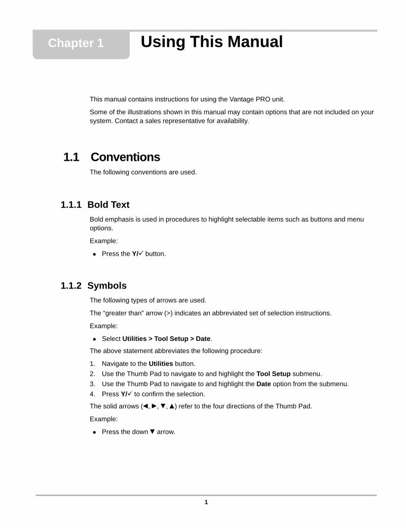
Chapter 1 Using This Manual
This manual contains instructions for using the Vantage PRO unit.
Some of the illustrations shown in this manual may contain options that are not included on your system. Contact a sales representative for availability.
1.1 ConventionsThe following conventions are used.
1.1.1 Bold Text
Bold emphasis is used in procedures to highlight selectable items such as buttons and menu options.
Example:
• Press the Y/a button.
1.1.2 Symbols
The following types of arrows are used.
The “greater than” arrow (>) indicates an abbreviated set of selection instructions.
Example:
• Select Utilities > Tool Setup > Date.
The above statement abbreviates the following procedure:
1. Navigate to the Utilities button.
2. Use the Thumb Pad to navigate to and highlight the Tool Setup submenu.
3. Use the Thumb Pad to navigate to and highlight the Date option from the submenu.
4. Press Y/a to confirm the selection.
The solid arrows (e, c, d, b) refer to the four directions of the Thumb Pad.
Example:
• Press the down d arrow.
1
Using This Manual Conventions
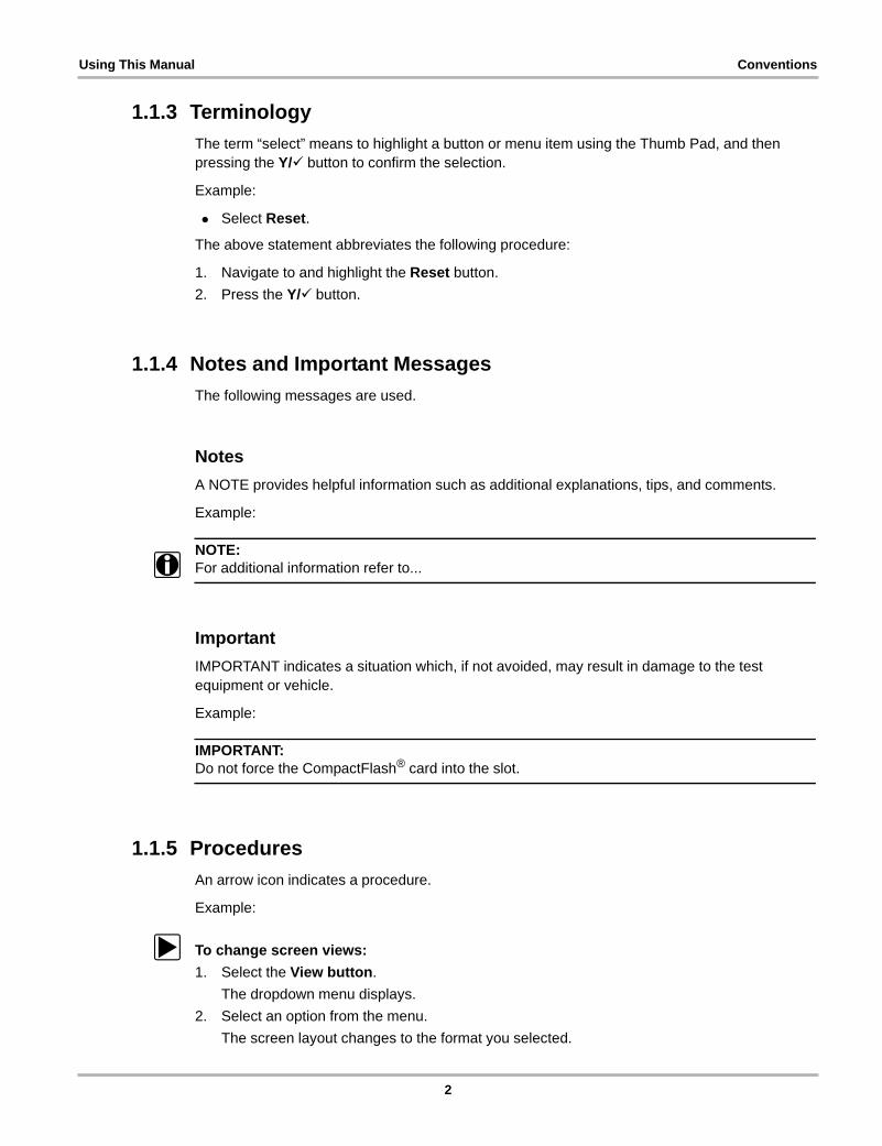
1.1.3 Terminology
The term “select” means to highlight a button or menu item using the Thumb Pad, and then pressing the Y/a button to confirm the selection.
Example:
• Select Reset.
The above statement abbreviates the following procedure:
1. Navigate to and highlight the Reset button.
2. Press the Y/a button.
1.1.4 Notes and Important Messages
The following messages are used.
Notes
A NOTE provides helpful information such as additional explanations, tips, and comments.
Example:
NOTE:i For additional information refer to...
Important
IMPORTANT indicates a situation which, if not avoided, may result in damage to the test equipment or vehicle.
Example:
IMPORTANT:Do not force the CompactFlash® card into the slot.
1.1.5 Procedures
An arrow icon indicates a procedure.
Example:
z To change screen views:
1. Select the View button.
The dropdown menu displays.
2. Select an option from the menu.
The screen layout changes to the format you selected.
2

Using This Manual Tool Help
1.2 Tool HelpYour Vantage PRO unit Tool Help contains reference and procedural information found in this manual. From the main menu, access Tool Help on the Utilities menu. See “Tool Help” on page 93 for details.
3
Chapter 2 Introduction
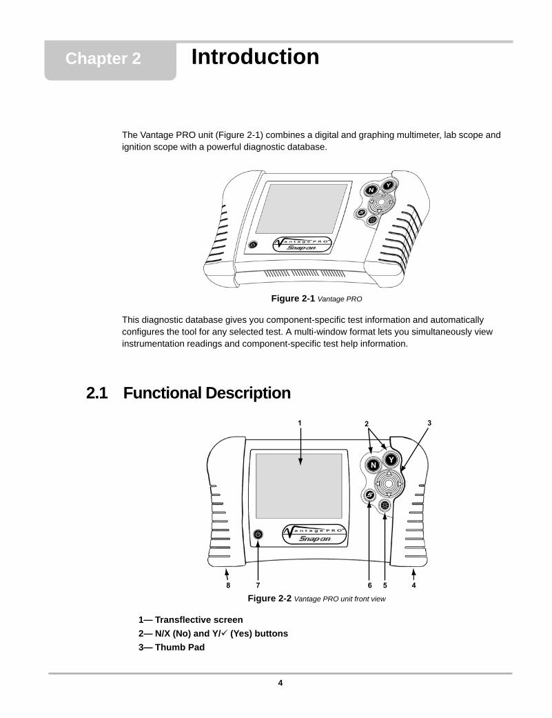
The Vantage PRO unit (Figure 2-1) combines a digital and graphing multimeter, lab scope and ignition scope with a powerful diagnostic database.
Figure 2-1 Vantage PRO
This diagnostic database gives you component-specific test information and automatically configures the tool for any selected test. A multi-window format lets you simultaneously view instrumentation readings and component-specific test help information.
2.1 Functional Description
Figure 2-2 Vantage PRO unit front view
1— Transflective screen
2— N/X (No) and Y/a (Yes) buttons
3— Thumb Pad
1 2 3
45678
4
Introduction Functional Description
4— Right handgrip
5— Brightness/Contrast button
6— S button
7— Power button
8— Left handgrip
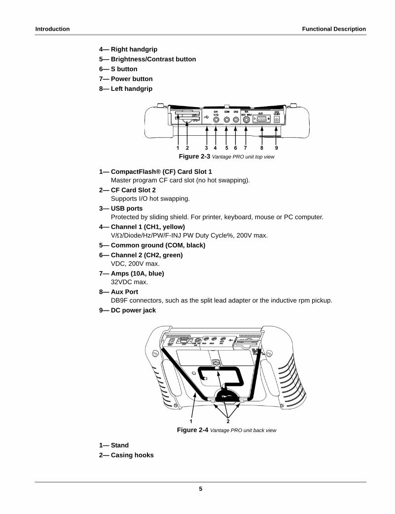
Figure 2-3 Vantage PRO unit top view
1— CompactFlash® (CF) Card Slot 1Master program CF card slot (no hot swapping).
2— CF Card Slot 2Supports I/O hot swapping.
3— USB portsProtected by sliding shield. For printer, keyboard, mouse or PC computer.
4— Channel 1 (CH1, yellow)V//Diode/Hz/PW/F-INJ PW Duty Cycle%, 200V max.
5— Common ground (COM, black)
6— Channel 2 (CH2, green)VDC, 200V max.
7— Amps (10A, blue)32VDC max.
8— Aux PortDB9F connectors, such as the split lead adapter or the inductive rpm pickup.
9— DC power jack
Figure 2-4 Vantage PRO unit back view
1— Stand
2— Casing hooks
1 2 3 4 5 6 7 8 9
1 2
5
Introduction The Stand
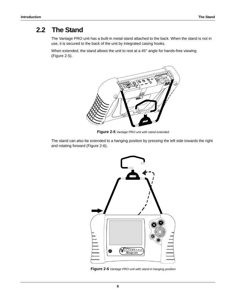
2.2 The StandThe Vantage PRO unit has a built-in metal stand attached to the back. When the stand is not in use, it is secured to the back of the unit by integrated casing hooks.
When extended, the stand allows the unit to rest at a 45° angle for hands-free viewing (Figure 2-5).
Figure 2-5 Vantage PRO unit with stand extended
The stand can also be extended to a hanging position by pressing the left side towards the right and rotating forward (Figure 2-6).
Figure 2-6 Vantage PRO unit with stand in hanging position
6

Introduction Technical Specifications
2.3 Technical Specifications
Display:
Transflective Liquid Crystal Display (LCD)
Visible under any lighting condition
320 x 240 resolution (1/4 VGA)
256 colors
5.7 inches (144.8 mm)
CompactFlash® (CF) Card Slot:
CF Type 1
Slot 1 is for the master program CF card
Slot 2 is for user options, such as a storage CF card
Battery Pack:
Nickel-metal hydride
Rechargeable
External Battery Charger:
Input: 100–240 V AC @ 0.5A, 47–63 Hz
Fuse:
10 Amp ATO® Mini
AC/DC Adapter:
2.5 mm DC plug
Input: 100–240V AC @ 0.5A, 47–63 Hz
Output: 15V DC @ 1.2A
Dimensions:
Width: 11.75 inches (298.45 mm)
Height: 6.90 inches (175.26 mm)
Depth: 2.40 inches (60.96 mm)
Weight (including battery pack):
3 lbs 12.5 oz (1.509 Kg)
Operating Temperature Range:
32 to 122°F (0 to 50°C)
Storage Temperature Range:
–4 to 140°F (–20 to 60°C)
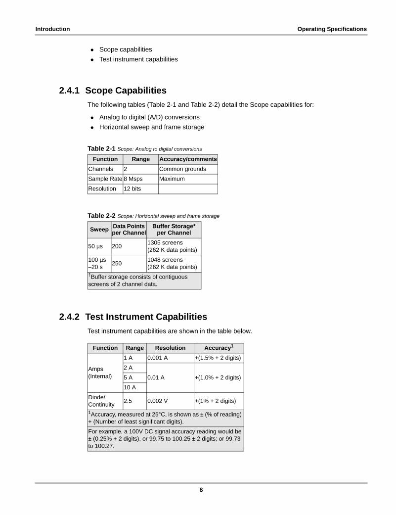
2.4 Operating SpecificationsThe following tables detail the Vantage PRO unit operating specifications for:
7
Introduction Operating Specifications
• Scope capabilities
• Test instrument capabilities
2.4.1 Scope Capabilities
The following tables (Table 2-1 and Table 2-2) detail the Scope capabilities for:
• Analog to digital (A/D) conversions
• Horizontal sweep and frame storage
2.4.2 Test Instrument Capabilities
Test instrument capabilities are shown in the table below.
Table 2-1 Scope: Analog to digital conversions
Function Range Accuracy/comments
Channels 2 Common grounds
Sample Rate 8 Msps Maximum
Resolution 12 bits
Table 2-2 Scope: Horizontal sweep and frame storage
Sweep Data Points per Channel
Buffer Storage* per Channel
50 µs 2001305 screens (262 K data points)
100 µs–20 s
2501048 screens (262 K data points)
†Buffer storage consists of contiguous screens of 2 channel data.
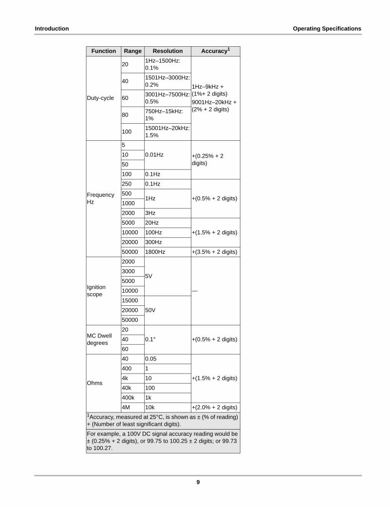
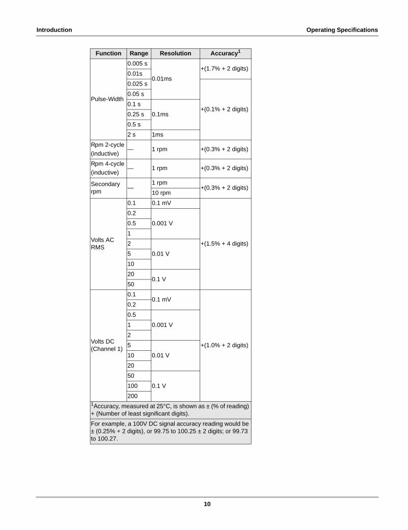
Function Range Resolution Accuracy1
Amps (Internal)
1 A 0.001 A +(1.5% + 2 digits)
2 A
0.01 A +(1.0% + 2 digits)5 A
10 A
Diode/Continuity
2.5 0.002 V +(1% + 2 digits)
1Accuracy, measured at 25°C, is shown as ± (% of reading) + (Number of least significant digits).
For example, a 100V DC signal accuracy reading would be ± (0.25% + 2 digits), or 99.75 to 100.25 ± 2 digits; or 99.73 to 100.27.
8
Introduction Operating Specifications
Duty-cycle
201Hz–1500Hz: 0.1%
1Hz–9kHz + (1%+ 2 digits)
9001Hz–20kHz + (2% + 2 digits)
401501Hz–3000Hz: 0.2%
603001Hz–7500Hz: 0.5%
80750Hz–15kHz: 1%
10015001Hz–20kHz: 1.5%
Frequency Hz
5
0.01Hz +(0.25% + 2 digits)
10
50
100 0.1Hz
250 0.1Hz
+(0.5% + 2 digits)500
1Hz1000
2000 3Hz
5000 20Hz
+(1.5% + 2 digits)10000 100Hz
20000 300Hz
50000 1800Hz +(3.5% + 2 digits)
Ignition scope
2000
5V
—
3000
5000
10000
15000
50V20000
50000
MC Dwell degrees
20
0.1° +(0.5% + 2 digits)40
60
Ohms
40 0.05
+(1.5% + 2 digits)
400 1
4k 10
40k 100
400k 1k
4M 10k +(2.0% + 2 digits)
Function Range Resolution Accuracy1
1Accuracy, measured at 25°C, is shown as ± (% of reading) + (Number of least significant digits).
For example, a 100V DC signal accuracy reading would be ± (0.25% + 2 digits), or 99.75 to 100.25 ± 2 digits; or 99.73 to 100.27.
9
Introduction Operating Specifications
Pulse-Width
0.005 s
0.01ms
+(1.7% + 2 digits)0.01s
0.025 s
+(0.1% + 2 digits)
0.05 s
0.1 s
0.1ms0.25 s
0.5 s
2 s 1ms
Rpm 2-cycle
(inductive)— 1 rpm +(0.3% + 2 digits)
Rpm 4-cycle
(inductive)— 1 rpm +(0.3% + 2 digits)
Secondary rpm
—1 rpm
+(0.3% + 2 digits)10 rpm
Volts AC RMS
0.1 0.1 mV
+(1.5% + 4 digits)
0.2
0.001 V0.5
1
2
0.01 V5
10
200.1 V
50
Volts DC (Channel 1)
0.10.1 mV
+(1.0% + 2 digits)
0.2
0.5
0.001 V1
2
5
0.01 V10
20
50
0.1 V100
200
Function Range Resolution Accuracy1
1Accuracy, measured at 25°C, is shown as ± (% of reading) + (Number of least significant digits).
For example, a 100V DC signal accuracy reading would be ± (0.25% + 2 digits), or 99.75 to 100.25 ± 2 digits; or 99.73 to 100.27.
10
Introduction Control Buttons
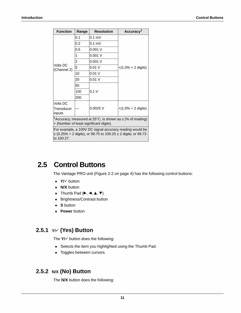
2.5 Control ButtonsThe Vantage PRO unit (Figure 2-2 on page 4) has the following control buttons:
• Y/a button
• N/X button
• Thumb Pad (c, e, b, d)
• Brightness/Contrast button
• S button
• Power button
2.5.1 Y/a (Yes) Button
The Y/a button does the following:
• Selects the item you highlighted using the Thumb Pad.
• Toggles between cursors.
2.5.2 N/X (No) Button
The N/X button does the following:
Volts DC (Channel 2)
0.1 0.1 mV
+(1.0% + 2 digits)
0.2 0.1 mV
0.5 0.001 V
1 0.001 V
2 0.001 V
5 0.01 V
10 0.01 V
20 0.01 V
50
0.1 V100
200
Volts DC
Transducer inputs
— 0.0025 V +(1.0% + 2 digits)
Function Range Resolution Accuracy1
1Accuracy, measured at 25°C, is shown as ± (% of reading) + (Number of least significant digits).
For example, a 100V DC signal accuracy reading would be ± (0.25% + 2 digits), or 99.75 to 100.25 ± 2 digits; or 99.73 to 100.27.
11
Introduction Connections
• Exits a menu or program.
• Moves the highlight between the upper and lower parts of the screen.
2.5.3 Thumb Pad
The Thumb Pad (c, e, b, d) moves the highlight around the screen for making menu or field selections and is typically used in combination with the Y/a and N/X buttons.
2.5.4 Brightness/Contrast Button
The Brightness/Contrast button lets you adjust the screen for optimum viewing. See “Adjusting Brightness and Contrast” on page 20 for details.
2.5.5 S Button
The S button can be customized to perform different functions from the Utilities > Tool Setup menu. See “S Button” on page 91 for details.
2.5.6 Power Button
The Power button powers the Vantage PRO unit on and off. The option to put the unit in Standby mode is also available. See “Powering Off the Unit” on page 22 for details.
2.6 ConnectionsThe Vantage PRO unit uses the following connections (Figure 2-3 on page 5):
• Test lead jacks
• DC power jack
• USB port
2.6.1 Test Lead Jacks
Standard safety banana jacks are used with test leads.
For related information, see the following sections:
• “Leads and Clips” on page 15
• “Connecting Leads and Clips” on page 21
12
Introduction Power Sources
2.6.2 DC Power Jack
The DC power jack can be used to power the unit with the AC/DC power adapter.
For related information, see the following sections:
• “AC/DC Power Adapter” on page 13
• “Connecting the AC/DC Power Adapter” on page 19
2.6.3 USB Port
The USB port can be used for connecting to a printer, keyboard or a PC.
For related information, see the following sections:
• “Setting Up to Print” on page 22
• “Editing Saved Files” on page 82
2.7 Power SourcesYour Vantage PRO unit can receive power from the following sources:
• AC/DC power adapter
• Battery pack (rechargeable)
• Vehicle power adapters (optional)
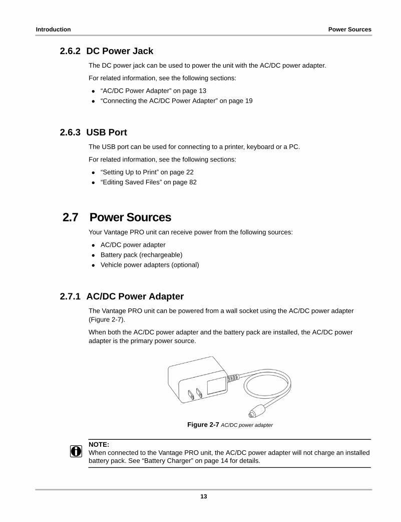
2.7.1 AC/DC Power Adapter
The Vantage PRO unit can be powered from a wall socket using the AC/DC power adapter (Figure 2-7).
When both the AC/DC power adapter and the battery pack are installed, the AC/DC power adapter is the primary power source.
Figure 2-7 AC/DC power adapter
NOTE:i When connected to the Vantage PRO unit, the AC/DC power adapter will not charge an installed
battery pack. See “Battery Charger” on page 14 for details.
13
Introduction Power Sources
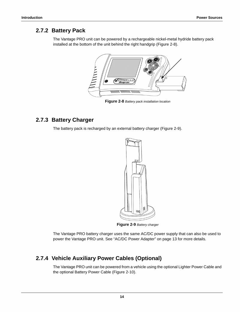
2.7.2 Battery Pack
The Vantage PRO unit can be powered by a rechargeable nickel-metal hydride battery pack installed at the bottom of the unit behind the right handgrip (Figure 2-8).
Figure 2-8 Battery pack installation location
2.7.3 Battery Charger
The battery pack is recharged by an external battery charger (Figure 2-9).
Figure 2-9 Battery charger
The Vantage PRO battery charger uses the same AC/DC power supply that can also be used to power the Vantage PRO unit. See “AC/DC Power Adapter” on page 13 for more details.
2.7.4 Vehicle Auxiliary Power Cables (Optional)
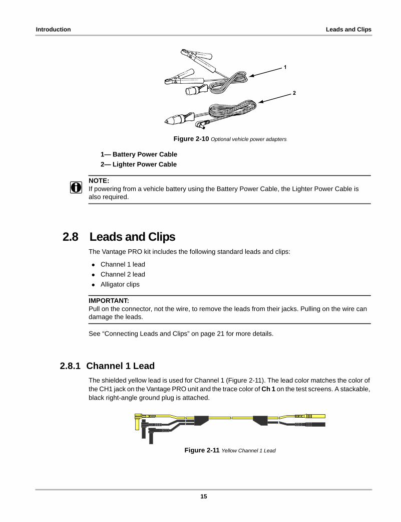
The Vantage PRO unit can be powered from a vehicle using the optional Lighter Power Cable and the optional Battery Power Cable (Figure 2-10).
14
Introduction Leads and Clips
Figure 2-10 Optional vehicle power adapters
1— Battery Power Cable
2— Lighter Power Cable
NOTE:i If powering from a vehicle battery using the Battery Power Cable, the Lighter Power Cable is
also required.
2.8 Leads and ClipsThe Vantage PRO kit includes the following standard leads and clips:
• Channel 1 lead
• Channel 2 lead
• Alligator clips
IMPORTANT:Pull on the connector, not the wire, to remove the leads from their jacks. Pulling on the wire can damage the leads.
See “Connecting Leads and Clips” on page 21 for more details.
2.8.1 Channel 1 Lead
The shielded yellow lead is used for Channel 1 (Figure 2-11). The lead color matches the color of the CH1 jack on the Vantage PRO unit and the trace color of Ch 1 on the test screens. A stackable, black right-angle ground plug is attached.
Figure 2-11 Yellow Channel 1 Lead
1
2
15
Introduction Leads and Clips
2.8.2 Channel 2 Lead
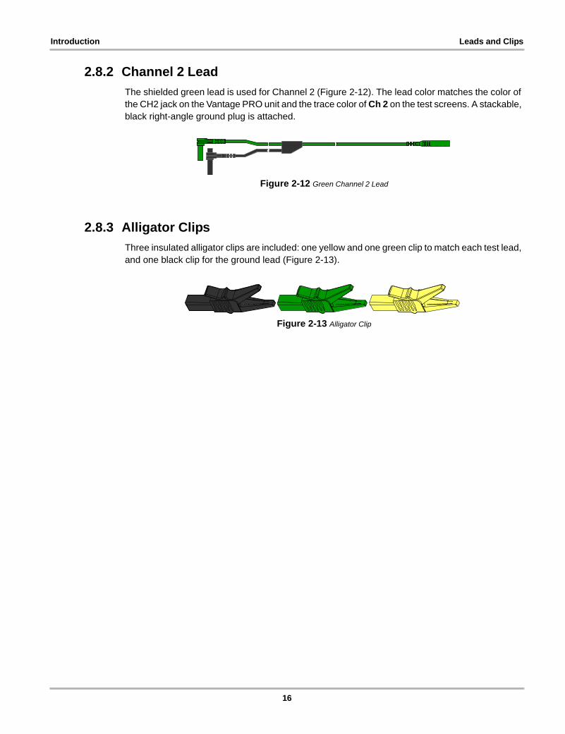
The shielded green lead is used for Channel 2 (Figure 2-12). The lead color matches the color of the CH2 jack on the Vantage PRO unit and the trace color of Ch 2 on the test screens. A stackable, black right-angle ground plug is attached.
Figure 2-12 Green Channel 2 Lead
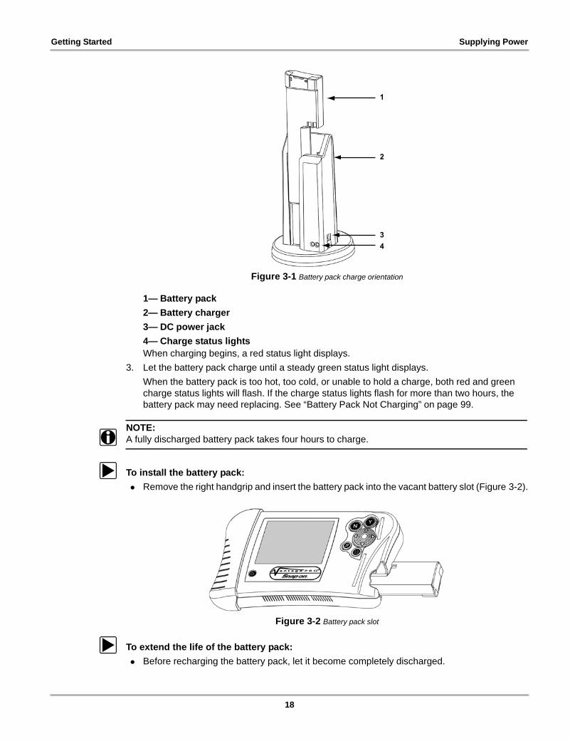
2.8.3 Alligator Clips
Three insulated alligator clips are included: one yellow and one green clip to match each test lead, and one black clip for the ground lead (Figure 2-13).
Figure 2-13 Alligator Clip
16

Chapter 3 Getting Started
This section explains how to get started using your Vantage PRO unit. The following procedures are covered:
1. Supplying power to the Vantage PRO unit
2. Turning on the unit
3. Adjusting Brightness/Contrast
4. Connecting leads and adapters
5. Setting up to print (optional)
6. Turning off the unit
3.1 Supplying PowerThere are several ways to supply power to the Vantage PRO unit:
• Using the Battery Pack
• Connecting the AC/DC Power Adapter
• Connecting Vehicle Auxiliary Power Cables
3.1.1 Using the Battery Pack
The Vantage PRO unit comes with a rechargeable nickel-metal hydride battery pack and an external battery charger.
For related information, see the following sections:
• “Battery Pack” on page 14
• “Battery Charger” on page 14
• “Replacing the Battery Pack” on page 97
• “Battery Pack Not Charging” on page 99
Before using the battery pack for the first time, you must fully charge it.
z To charge the battery pack:
1. Plug the AC/DC power adapter into the DC power jack of the battery charger.
NOTE:i Do not put a hot battery pack in the battery charger unit. Allow the battery pack to cool first. For
optimal battery charging, the ideal room temperature is 77°F (25°C) ±5°.
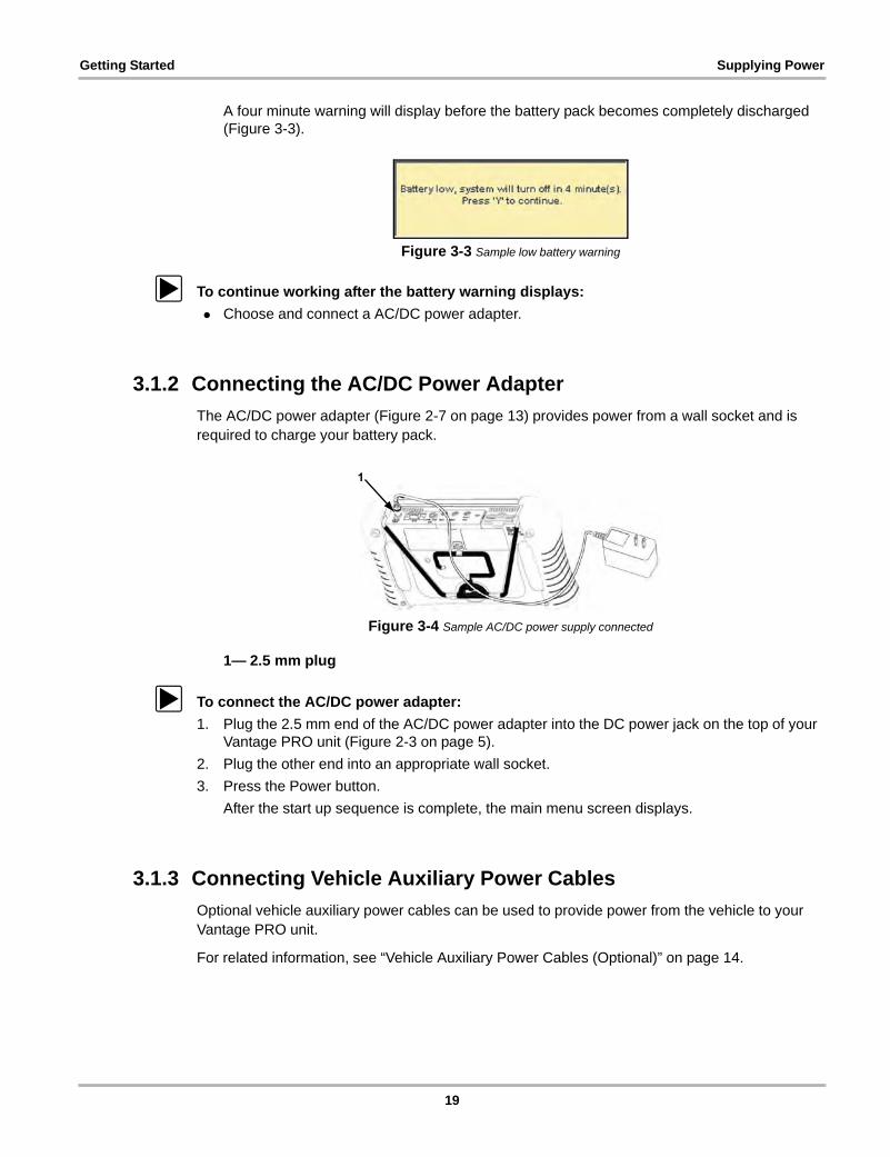
2. Vertically insert the battery pack into the charger (Figure 3-1).
17
Getting Started Supplying Power
Figure 3-1 Battery pack charge orientation
1— Battery pack
2— Battery charger
3— DC power jack
4— Charge status lightsWhen charging begins, a red status light displays.
3. Let the battery pack charge until a steady green status light displays.
When the battery pack is too hot, too cold, or unable to hold a charge, both red and green charge status lights will flash. If the charge status lights flash for more than two hours, the battery pack may need replacing. See “Battery Pack Not Charging” on page 99.
NOTE:i A fully discharged battery pack takes four hours to charge.
z To install the battery pack:
• Remove the right handgrip and insert the battery pack into the vacant battery slot (Figure 3-2).
Figure 3-2 Battery pack slot
z To extend the life of the battery pack:
• Before recharging the battery pack, let it become completely discharged.
1
2
34
18
Getting Started Supplying Power
A four minute warning will display before the battery pack becomes completely discharged (Figure 3-3).
Figure 3-3 Sample low battery warning
z To continue working after the battery warning displays:
• Choose and connect a AC/DC power adapter.
3.1.2 Connecting the AC/DC Power Adapter
The AC/DC power adapter (Figure 2-7 on page 13) provides power from a wall socket and is required to charge your battery pack.
Figure 3-4 Sample AC/DC power supply connected
1— 2.5 mm plug
z To connect the AC/DC power adapter:
1. Plug the 2.5 mm end of the AC/DC power adapter into the DC power jack on the top of your Vantage PRO unit (Figure 2-3 on page 5).
2. Plug the other end into an appropriate wall socket.
3. Press the Power button.
After the start up sequence is complete, the main menu screen displays.
3.1.3 Connecting Vehicle Auxiliary Power Cables
Optional vehicle auxiliary power cables can be used to provide power from the vehicle to your Vantage PRO unit.
For related information, see “Vehicle Auxiliary Power Cables (Optional)” on page 14.
1
19
Getting Started Powering On the Unit
z To connect the vehicle auxiliary power cables:
1. Plug the 2.5 mm end of the Lighter Power Cable into the DC power jack on top of the Vantage PRO™ unit.
2. Plug the other end of the Lighter Power Cable into either the cigarette lighter or the Battery Power Cable receiver.
3. If the Battery Power Cable is used, clip the other ends of the Battery Power Cable to the positive and negative battery terminals of your test vehicle.
3.2 Powering On the UnitWhen a master storage CF card is installed in slot 1 and power is supplied, you can power on the Vantage PRO™ unit.
For related information, see:
• “Supplying Power” on page 17
• “Powering Off the Unit” on page 22
• “Unit Will Not Power On” on page 99
z To power on the Vantage PRO unit:
• Press and hold the Power button (Figure 2-2 on page 4) until the unit beeps.
After a few seconds the main menu screen displays.
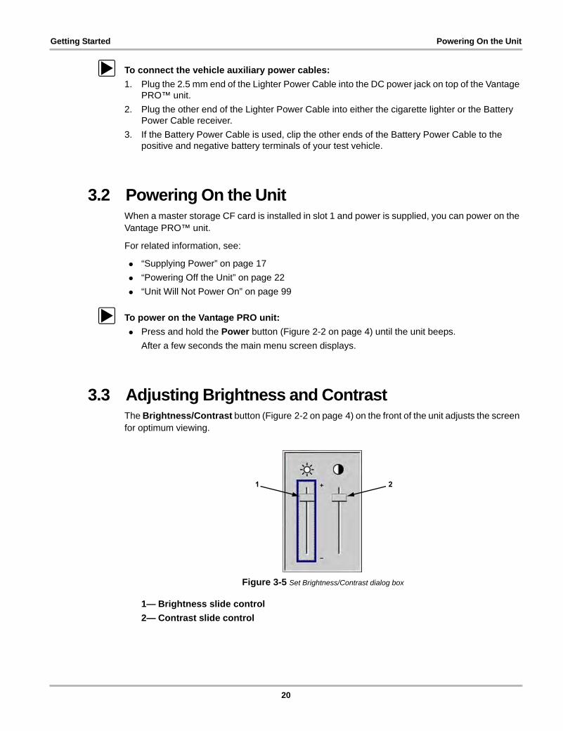
3.3 Adjusting Brightness and ContrastThe Brightness/Contrast button (Figure 2-2 on page 4) on the front of the unit adjusts the screen for optimum viewing.
Figure 3-5 Set Brightness/Contrast dialog box
1— Brightness slide control
2— Contrast slide control
1 2
20
Getting Started Connecting Leads and Clips
z To adjust brightness and contrast:
1. Press the Brightness/Contrast button.
The Set Brightness/Contrast dialog box displays (Figure 3-5).
2. Select a slide control using the right c or left e arrows.
3. Press the up b or down d arrows to adjust brightness and contrast.
4. Press N/X to close the dialog box.
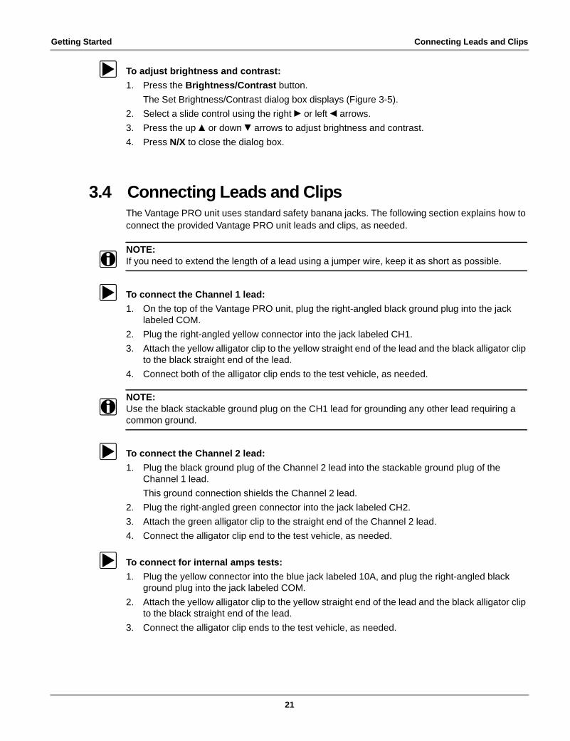
3.4 Connecting Leads and ClipsThe Vantage PRO unit uses standard safety banana jacks. The following section explains how to connect the provided Vantage PRO unit leads and clips, as needed.
NOTE:i If you need to extend the length of a lead using a jumper wire, keep it as short as possible.
z To connect the Channel 1 lead:
1. On the top of the Vantage PRO unit, plug the right-angled black ground plug into the jack labeled COM.
2. Plug the right-angled yellow connector into the jack labeled CH1.
3. Attach the yellow alligator clip to the yellow straight end of the lead and the black alligator clip to the black straight end of the lead.
4. Connect both of the alligator clip ends to the test vehicle, as needed.
NOTE:i Use the black stackable ground plug on the CH1 lead for grounding any other lead requiring a
common ground.
z To connect the Channel 2 lead:
1. Plug the black ground plug of the Channel 2 lead into the stackable ground plug of the Channel 1 lead.
This ground connection shields the Channel 2 lead.
2. Plug the right-angled green connector into the jack labeled CH2.
3. Attach the green alligator clip to the straight end of the Channel 2 lead.
4. Connect the alligator clip end to the test vehicle, as needed.
z To connect for internal amps tests:
1. Plug the yellow connector into the blue jack labeled 10A, and plug the right-angled black ground plug into the jack labeled COM.
2. Attach the yellow alligator clip to the yellow straight end of the lead and the black alligator clip to the black straight end of the lead.
3. Connect the alligator clip ends to the test vehicle, as needed.
21
Getting Started Setting Up to Print
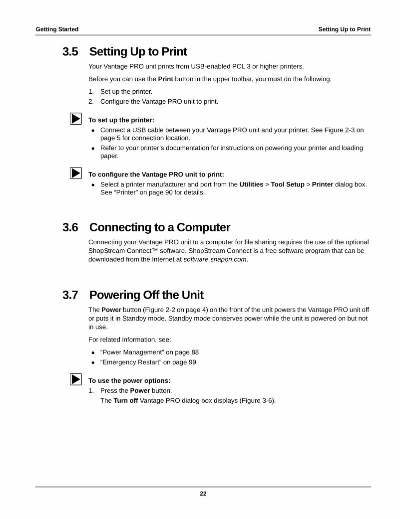
3.5 Setting Up to PrintYour Vantage PRO unit prints from USB-enabled PCL 3 or higher printers.
Before you can use the Print button in the upper toolbar, you must do the following:
1. Set up the printer.
2. Configure the Vantage PRO unit to print.
z To set up the printer:
• Connect a USB cable between your Vantage PRO unit and your printer. See Figure 2-3 on page 5 for connection location.
• Refer to your printer’s documentation for instructions on powering your printer and loading paper.
z To configure the Vantage PRO unit to print:
• Select a printer manufacturer and port from the Utilities > Tool Setup > Printer dialog box. See “Printer” on page 90 for details.
3.6 Connecting to a ComputerConnecting your Vantage PRO unit to a computer for file sharing requires the use of the optional ShopStream Connect™ software. ShopStream Connect is a free software program that can be downloaded from the Internet at software.snapon.com.
3.7 Powering Off the UnitThe Power button (Figure 2-2 on page 4) on the front of the unit powers the Vantage PRO unit off or puts it in Standby mode. Standby mode conserves power while the unit is powered on but not in use.
For related information, see:
• “Power Management” on page 88
• “Emergency Restart” on page 99
z To use the power options:
1. Press the Power button.
The Turn off Vantage PRO dialog box displays (Figure 3-6).
22

Getting Started Powering Off the Unit
Figure 3-6 Turn off Vantage PRO dialog box
2. Select either Standby or Turn off, or press N/X to cancel.
z To exit Standby mode:
• Press any button or the Thumb Pad.
23
Chapter 4 Navigation
This section describes basic screen layout and general Vantage PRO unit navigation.
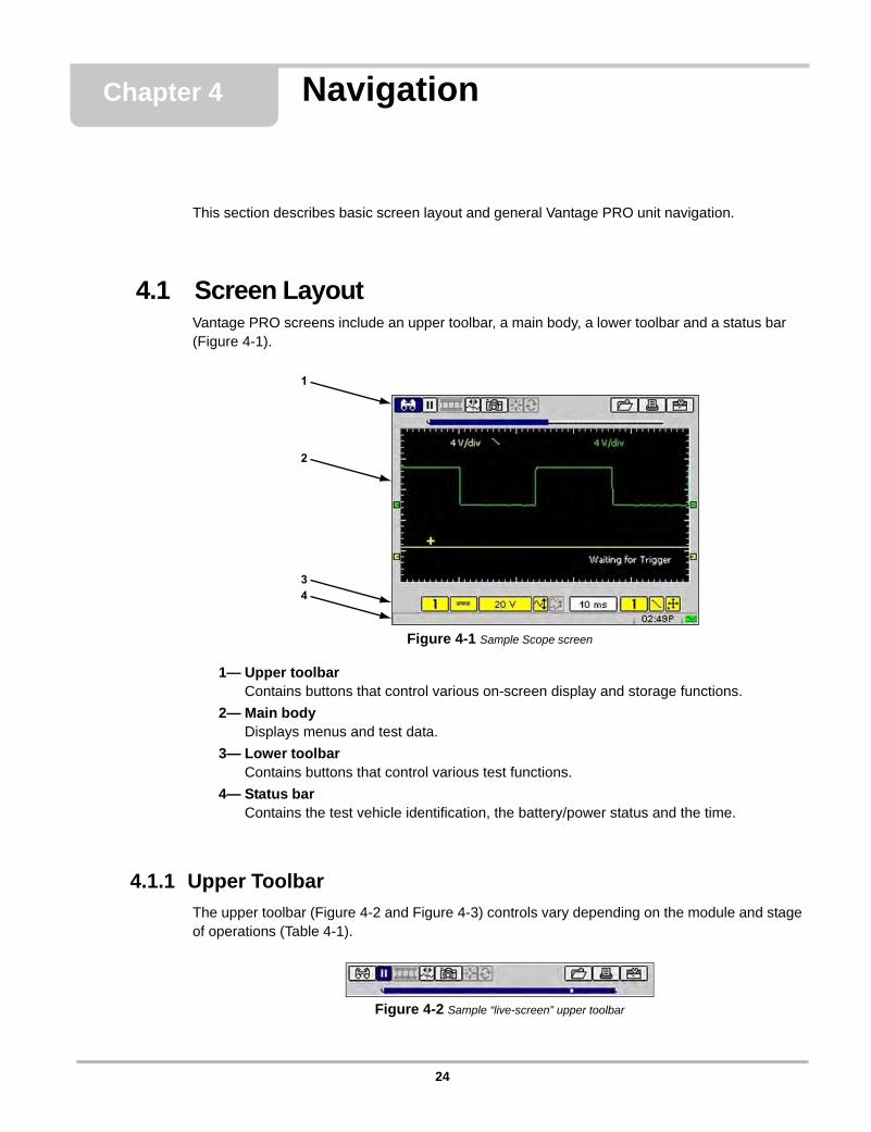
4.1 Screen LayoutVantage PRO screens include an upper toolbar, a main body, a lower toolbar and a status bar (Figure 4-1).
Figure 4-1 Sample Scope screen
1— Upper toolbarContains buttons that control various on-screen display and storage functions.
2— Main bodyDisplays menus and test data.
3— Lower toolbarContains buttons that control various test functions.
4— Status barContains the test vehicle identification, the battery/power status and the time.
4.1.1 Upper Toolbar
The upper toolbar (Figure 4-2 and Figure 4-3) controls vary depending on the module and stage of operations (Table 4-1).
Figure 4-2 Sample “live-screen” upper toolbar
24
Navigation Screen Layout
Figure 4-3 Sample “paused-screen” upper toolbar
Data Buffer
The Data Buffer (Figure 4-4) is located just below the upper toolbar buttons and indicates how much test data is stored.
Figure 4-4 Sample Data Buffer
1— Pause button
2— Data Buffer
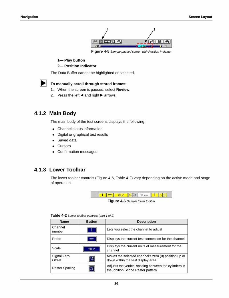
When the screen is paused, the position indicator displays the current frame number and the amount of data on the screen relative to the total data captured (Figure 4-5).
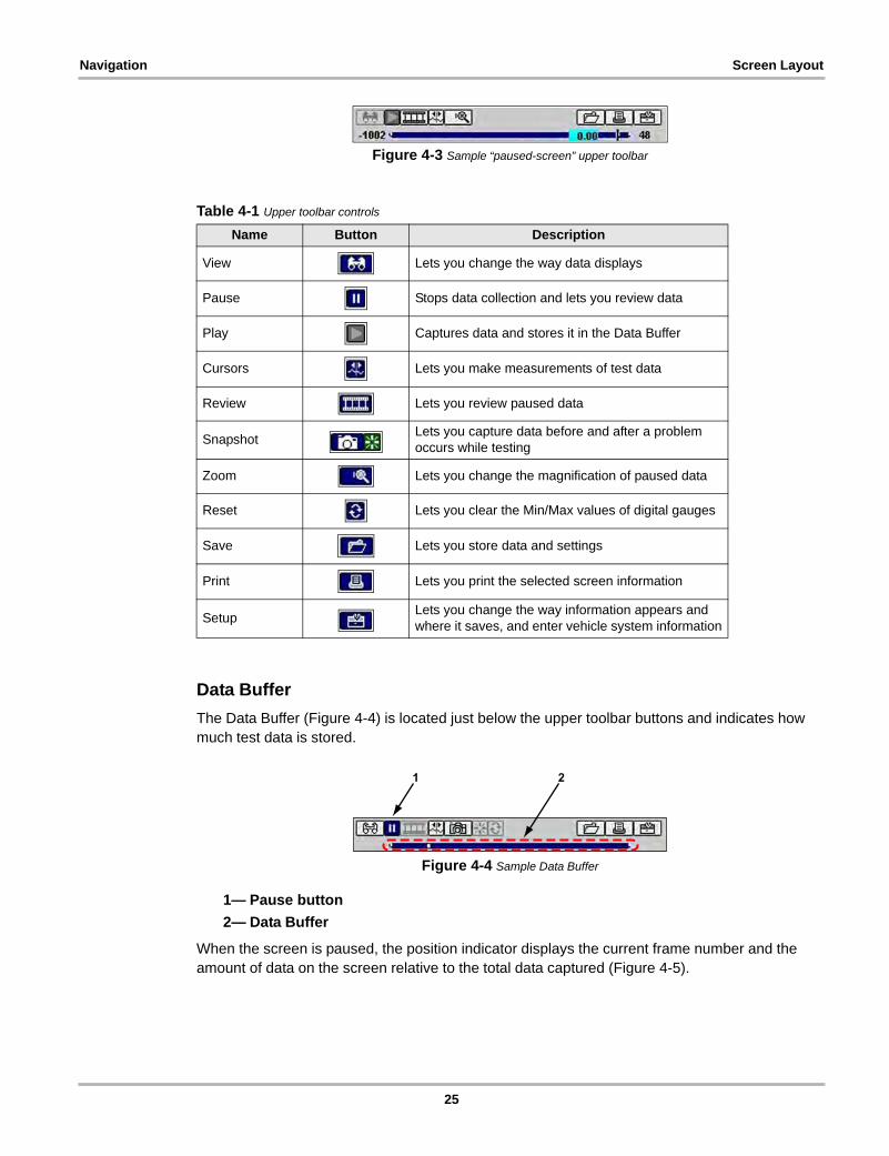
Table 4-1 Upper toolbar controls
Name Button Description
View Lets you change the way data displays
Pause Stops data collection and lets you review data
Play Captures data and stores it in the Data Buffer
Cursors Lets you make measurements of test data
Review Lets you review paused data
SnapshotLets you capture data before and after a problem occurs while testing
Zoom Lets you change the magnification of paused data
Reset Lets you clear the Min/Max values of digital gauges
Save Lets you store data and settings
Print Lets you print the selected screen information
SetupLets you change the way information appears and where it saves, and enter vehicle system information
25
Navigation Screen Layout
Figure 4-5 Sample paused screen with Position Indicator
1— Play button
2— Position Indicator
The Data Buffer cannot be highlighted or selected.
z To manually scroll through stored frames:
1. When the screen is paused, select Review.
2. Press the left e and right c arrows.
4.1.2 Main Body
The main body of the test screens displays the following:
• Channel status information
• Digital or graphical test results
• Saved data
• Cursors
• Confirmation messages
4.1.3 Lower Toolbar
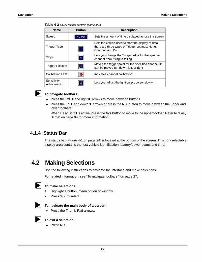
The lower toolbar controls (Figure 4-6, Table 4-2) vary depending on the active mode and stage of operation.
Figure 4-6 Sample lower toolbar
Table 4-2 Lower toolbar controls (part 1 of 2)
Name Button Description
Channel number
Lets you select the channel to adjust
Probe Displays the current test connection for the channel
ScaleDisplays the current units of measurement for the channel
Signal Zero Offset
Moves the selected channel’s zero (0) position up or down within the test display area
Raster SpacingAdjusts the vertical spacing between the cylinders in the Ignition Scope Raster pattern
26
Navigation Making Selections
z To navigate toolbars:
• Press the left e and right c arrows to move between buttons.
• Press the up b and down d arrows or press the N/X button to move between the upper and lower toolbars.
When Easy Scroll is active, press the N/X button to move to the upper toolbar. Refer to “Easy Scroll” on page 94 for more information.
4.1.4 Status Bar
The status bar (Figure 4-1 on page 24) is located at the bottom of the screen. This non-selectable display area contains the test vehicle identification, battery/power status and time.
4.2 Making SelectionsUse the following instructions to navigate the interface and make selections.
For related information, see “To navigate toolbars:” on page 27.
z To make selections:
1. Highlight a button, menu option or window.
2. Press Y/a to select.
z To navigate the main body of a screen:
• Press the Thumb Pad arrows.
z To exit a selection
• Press N/X.
Sweep Sets the amount of time displayed across the screen
Trigger TypeSets the criteria used to start the display of data–there are three types of Trigger settings: None, Channel, and Cyl
SlopeLets you change the Trigger edge for the specified channel from rising to falling
Trigger PositionMoves the trigger point for the specified channel–it can be moved up, down, left, or right
Calibration LED Indicates channel calibration
Sensitivity Adjustment
Lets you adjust the ignition scope sensitivity.
Table 4-2 Lower toolbar controls (part 2 of 2)
Name Button Description
27
Navigation Making Selections
4.2.1 Navigating Multi-Window Screens
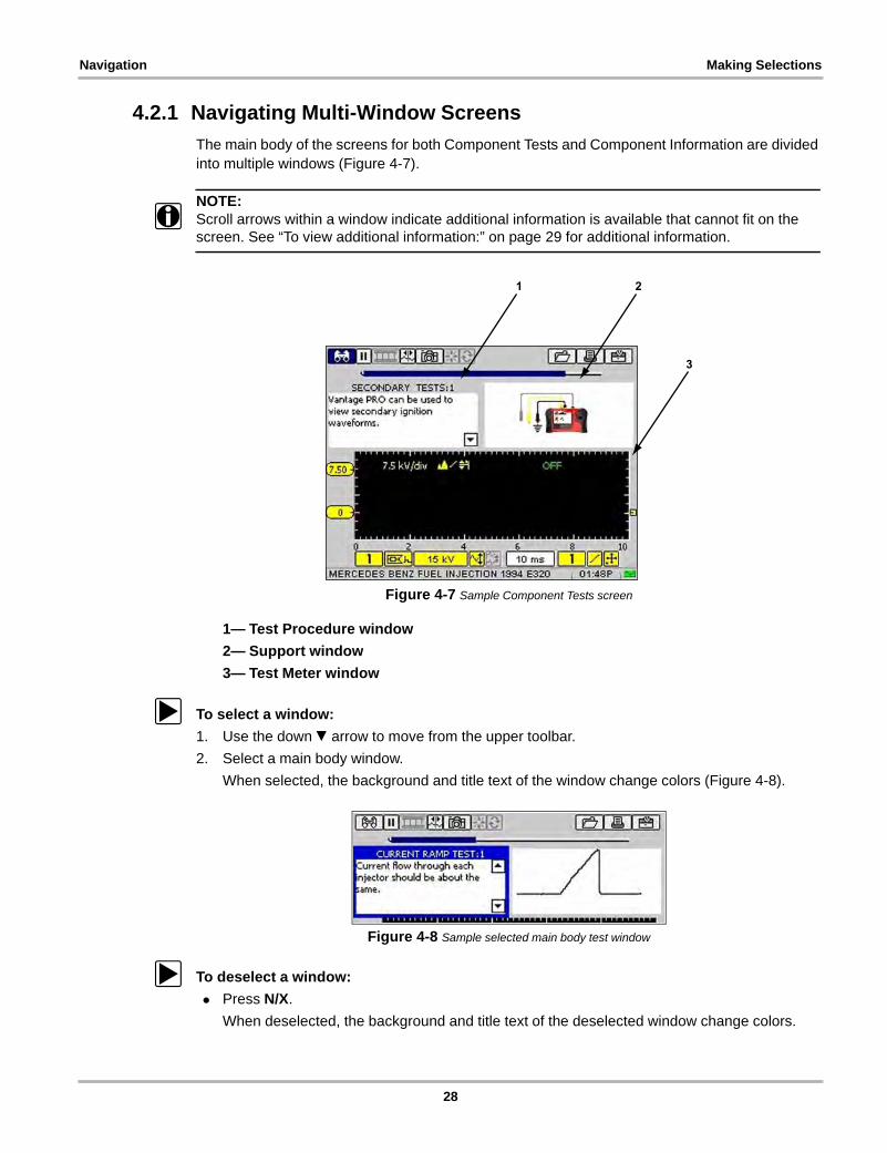
The main body of the screens for both Component Tests and Component Information are divided into multiple windows (Figure 4-7).
NOTE:i Scroll arrows within a window indicate additional information is available that cannot fit on the
screen. See “To view additional information:” on page 29 for additional information.
Figure 4-7 Sample Component Tests screen
1— Test Procedure window
2— Support window
3— Test Meter window
z To select a window:
1. Use the down d arrow to move from the upper toolbar.
2. Select a main body window.
When selected, the background and title text of the window change colors (Figure 4-8).
Figure 4-8 Sample selected main body test window
z To deselect a window:
• Press N/X.
When deselected, the background and title text of the deselected window change colors.
28
Navigation Easy Scroll
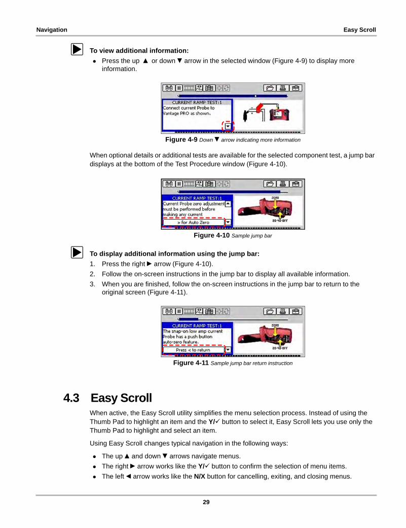
z To view additional information:
• Press the up b or down d arrow in the selected window (Figure 4-9) to display more information.
Figure 4-9 Down d arrow indicating more information
When optional details or additional tests are available for the selected component test, a jump bar displays at the bottom of the Test Procedure window (Figure 4-10).
Figure 4-10 Sample jump bar
z To display additional information using the jump bar:
1. Press the right c arrow (Figure 4-10).
2. Follow the on-screen instructions in the jump bar to display all available information.
3. When you are finished, follow the on-screen instructions in the jump bar to return to the original screen (Figure 4-11).
Figure 4-11 Sample jump bar return instruction
4.3 Easy ScrollWhen active, the Easy Scroll utility simplifies the menu selection process. Instead of using the Thumb Pad to highlight an item and the Y/a button to select it, Easy Scroll lets you use only the Thumb Pad to highlight and select an item.
Using Easy Scroll changes typical navigation in the following ways:
• The up b and down d arrows navigate menus.
• The right c arrow works like the Y/a button to confirm the selection of menu items.
• The left e arrow works like the N/X button for cancelling, exiting, and closing menus.
29
Navigation Screen Messages
The Easy Scroll utility functions differently depending on the module. For example, in modules that have upper and lower toolbars, the up b arrow cannot be used to navigate to the upper toolbar. In this instance, use either N/X or the left e and right c arrows (in a figure-8 pattern) to move out of the lower toolbar.
Refer to “Easy Scroll” on page 94 for information on activating Easy Scroll.
4.4 Screen MessagesThe Vantage PRO unit displays three types of messages:
• Confirmation Messages
• Warning Messages
• Error Messages
z To manage on-screen messages:
• Follow the instructions included with the message.
4.4.1 Confirmation Messages
Confirmation messages inform you when you are about to perform an action that cannot be reversed or when an action has been initiated and your confirmation is needed to continue.
When a user response is not required, the message displays briefly before automatically disappearing.
4.4.2 Warning Messages
Warning messages inform you when completing the selected action may result in an irreversible change or loss of data.
4.4.3 Error Messages
Error messages inform you when a failure has occurred.
Example causes of possible errors include:
• when a cable is disconnected;
• when a printer is powered off.
30
Chapter 5 Component Test Operations
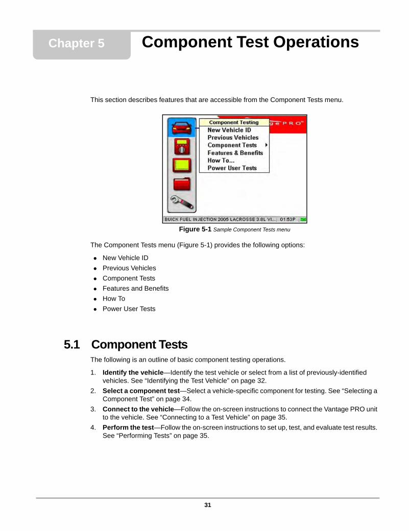
This section describes features that are accessible from the Component Tests menu.
Figure 5-1 Sample Component Tests menu
The Component Tests menu (Figure 5-1) provides the following options:
• New Vehicle ID
• Previous Vehicles
• Component Tests
• Features and Benefits
• How To
• Power User Tests
5.1 Component TestsThe following is an outline of basic component testing operations.
1. Identify the vehicle—Identify the test vehicle or select from a list of previously-identified vehicles. See “Identifying the Test Vehicle” on page 32.
2. Select a component test—Select a vehicle-specific component for testing. See “Selecting a Component Test” on page 34.
3. Connect to the vehicle—Follow the on-screen instructions to connect the Vantage PRO unit to the vehicle. See “Connecting to a Test Vehicle” on page 35.
4. Perform the test—Follow the on-screen instructions to set up, test, and evaluate test results. See “Performing Tests” on page 35.
31
Component Test Operations Identifying the Test Vehicle
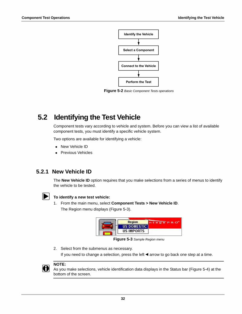
Figure 5-2 Basic Component Tests operations
5.2 Identifying the Test VehicleComponent tests vary according to vehicle and system. Before you can view a list of available component tests, you must identify a specific vehicle system.
Two options are available for identifying a vehicle:
• New Vehicle ID
• Previous Vehicles
5.2.1 New Vehicle ID
The New Vehicle ID option requires that you make selections from a series of menus to identify the vehicle to be tested.
z To identify a new test vehicle:
1. From the main menu, select Component Tests > New Vehicle ID.
The Region menu displays (Figure 5-3).
Figure 5-3 Sample Region menu
2. Select from the submenus as necessary.
If you need to change a selection, press the left e arrow to go back one step at a time.
NOTE:i As you make selections, vehicle identification data displays in the Status bar (Figure 5-4) at the
bottom of the screen.
Identify the Vehicle
Select a Component
Connect to the Vehicle
Perform the Test
32
Component Test Operations Identifying the Test Vehicle
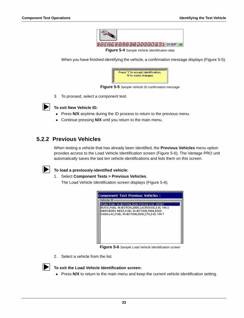
Figure 5-4 Sample Vehicle Identification data
When you have finished identifying the vehicle, a confirmation message displays (Figure 5-5).
Figure 5-5 Sample Vehicle ID confirmation message
3. To proceed, select a component test.
z To exit New Vehicle ID:
• Press N/X anytime during the ID process to return to the previous menu.
• Continue pressing N/X until you return to the main menu.
5.2.2 Previous Vehicles
When testing a vehicle that has already been identified, the Previous Vehicles menu option provides access to the Load Vehicle Identification screen (Figure 5-6). The Vantage PRO unit automatically saves the last ten vehicle identifications and lists them on this screen.
z To load a previously-identified vehicle:
1. Select Component Tests > Previous Vehicles.
The Load Vehicle Identification screen displays (Figure 5-6).
Figure 5-6 Sample Load Vehicle Identification screen
2. Select a vehicle from the list.
z To exit the Load Vehicle Identification screen:
• Press N/X to return to the main menu and keep the current vehicle identification setting.
33

Component Test Operations Selecting a Component Test
5.3 Selecting a Component TestOnce a test vehicle is identified, you can select from the Component Tests menu.
The main body (Figure 5-10) of the test screen can contain the following sections:
• Test Procedure window—contains connection and testing procedures.
• Support window—contains support information, such as connector illustrations.
• Test Meter window—functions as a Graphing Meter, Digital Meter, or Lab Scope, depending on the selected test.
z To select a component test:
1. Select Component Tests > Component Tests.
The Component Tests menu displays the available components for the identified test vehicle (Figure 5-7).
Figure 5-7 Sample Component Tests menu
2. Select a component.
The component menu displays (Figure 5-8).
Figure 5-8 Sample component menu
3. Select TESTS.
A Tests menu displays (Figure 5-9).
Figure 5-9 Sample TESTS menu
4. Select a test.
The Test screen displays (Figure 5-10).
34
Component Test Operations Connecting to a Test Vehicle
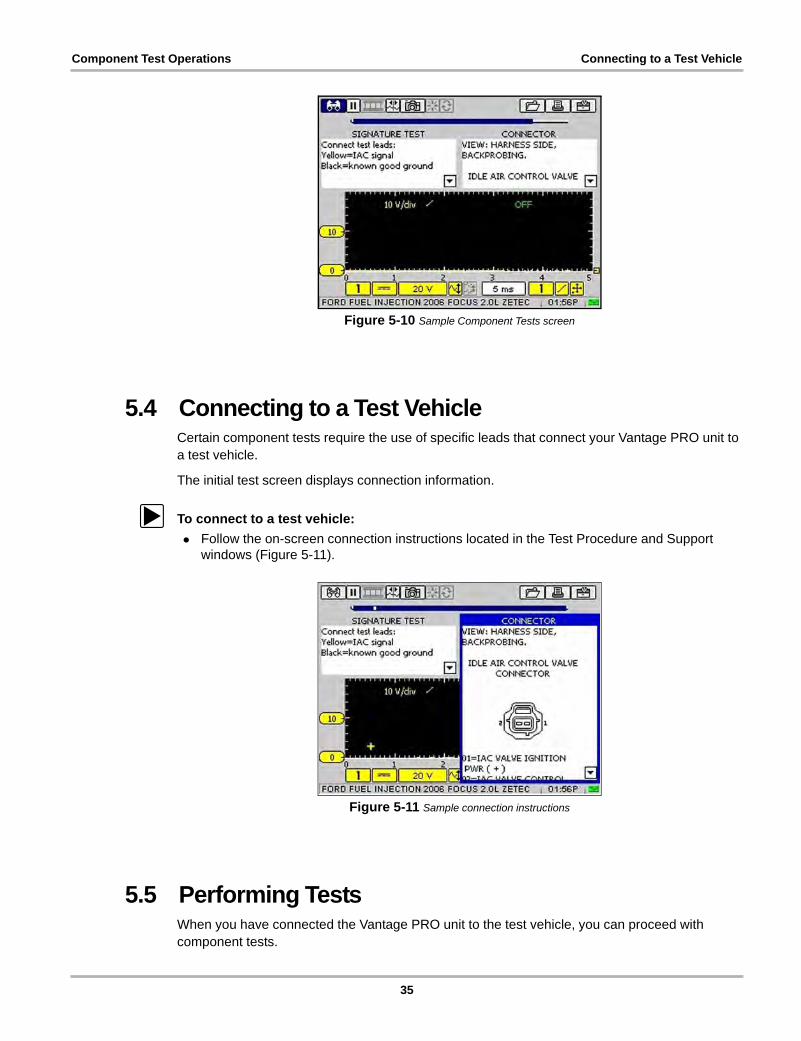
Figure 5-10 Sample Component Tests screen
5.4 Connecting to a Test VehicleCertain component tests require the use of specific leads that connect your Vantage PRO unit to a test vehicle.
The initial test screen displays connection information.
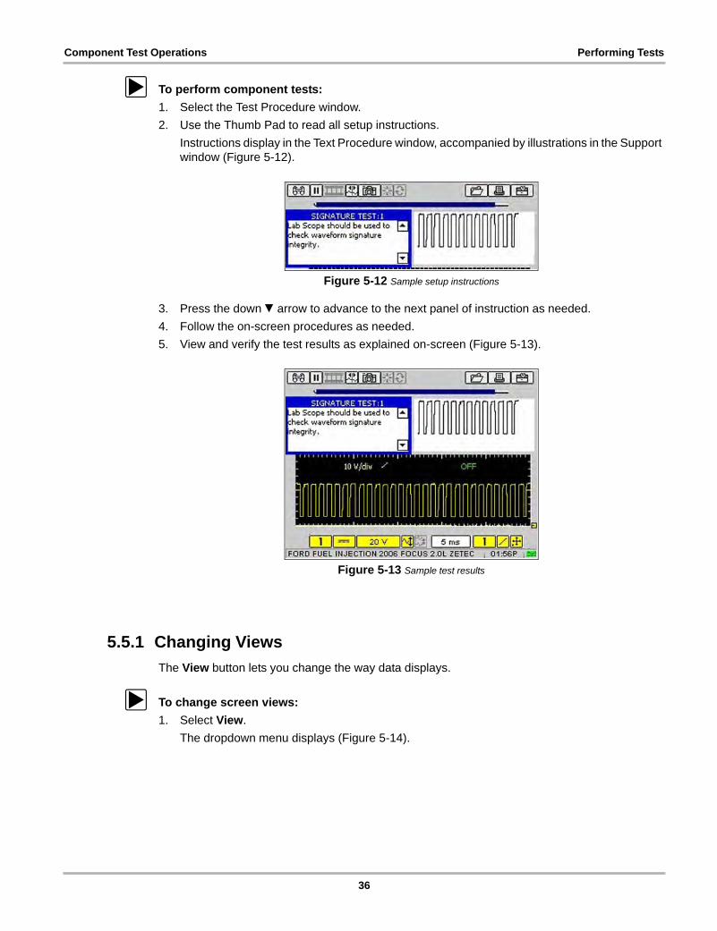
z To connect to a test vehicle:
• Follow the on-screen connection instructions located in the Test Procedure and Support windows (Figure 5-11).
Figure 5-11 Sample connection instructions
5.5 Performing TestsWhen you have connected the Vantage PRO unit to the test vehicle, you can proceed with component tests.
35
Component Test Operations Performing Tests
z To perform component tests:
1. Select the Test Procedure window.
2. Use the Thumb Pad to read all setup instructions.
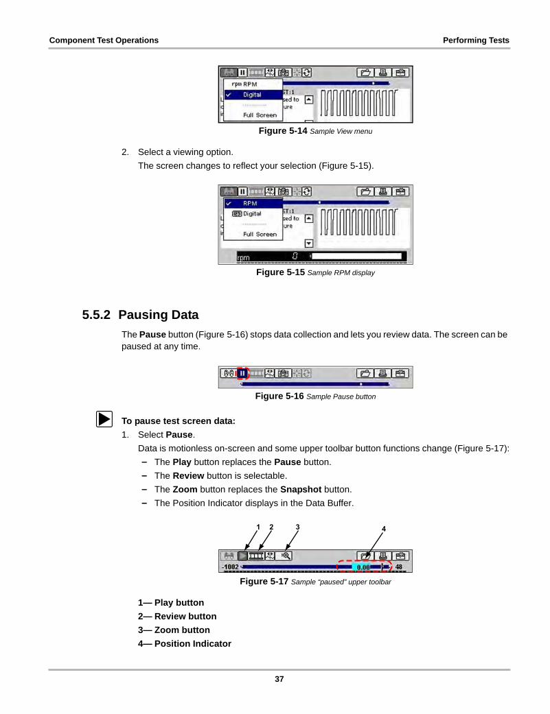
Instructions display in the Text Procedure window, accompanied by illustrations in the Support window (Figure 5-12).
Figure 5-12 Sample setup instructions
3. Press the down d arrow to advance to the next panel of instruction as needed.
4. Follow the on-screen procedures as needed.
5. View and verify the test results as explained on-screen (Figure 5-13).
Figure 5-13 Sample test results
5.5.1 Changing Views
The View button lets you change the way data displays.
z To change screen views:
1. Select View.
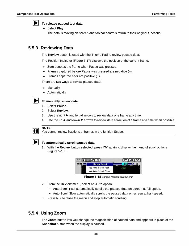
The dropdown menu displays (Figure 5-14).
36
Component Test Operations Performing Tests
Figure 5-14 Sample View menu
2. Select a viewing option.
The screen changes to reflect your selection (Figure 5-15).
Figure 5-15 Sample RPM display
5.5.2 Pausing Data
The Pause button (Figure 5-16) stops data collection and lets you review data. The screen can be paused at any time.
Figure 5-16 Sample Pause button
z To pause test screen data:
1. Select Pause.
Data is motionless on-screen and some upper toolbar button functions change (Figure 5-17):
– The Play button replaces the Pause button.
– The Review button is selectable.
– The Zoom button replaces the Snapshot button.
– The Position Indicator displays in the Data Buffer.
Figure 5-17 Sample “paused” upper toolbar
1— Play button
2— Review button
3— Zoom button
4— Position Indicator
37
Component Test Operations Performing Tests
z To release paused test data:
• Select Play.
The data is moving on-screen and toolbar controls return to their original functions.
5.5.3 Reviewing Data
The Review button is used with the Thumb Pad to review paused data.
The Position Indicator (Figure 5-17) displays the position of the current frame.
• Zero denotes the frame when Pause was pressed.
• Frames captured before Pause was pressed are negative (–).
• Frames captured after are positive (+).
There are two ways to review paused data:
• Manually
• Automatically
z To manually review data:
1. Select Pause.
2. Select Review.
3. Use the right c and left e arrows to review data one frame at a time.
4. Use the up b and down d arrows to review data a fraction of a frame at a time when possible.
NOTE:i You cannot review fractions of frames in the Ignition Scope.
z To automatically scroll paused data:
1. With the Review button selected, press Y/a again to display the menu of scroll options (Figure 5-18).
Figure 5-18 Sample Review scroll menu
2. From the Review menu, select an Auto option.
– Auto Scroll Fast automatically scrolls the paused data on-screen at full-speed.
– Auto Scroll Slow automatically scrolls the paused data on-screen at half-speed.
3. Press N/X to close the menu and stop automatic scrolling.
5.5.4 Using Zoom
The Zoom button lets you change the magnification of paused data and appears in place of the Snapshot button when the display is paused.
38
Component Test Operations Performing Tests
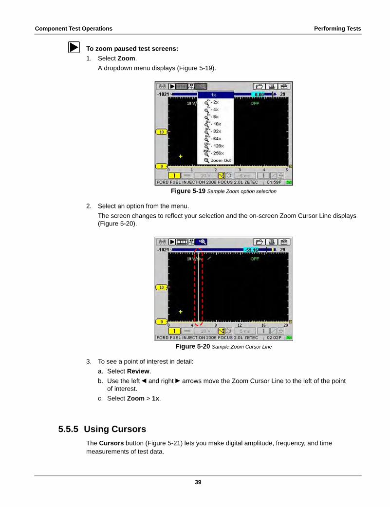
z To zoom paused test screens:
1. Select Zoom.
A dropdown menu displays (Figure 5-19).
Figure 5-19 Sample Zoom option selection
2. Select an option from the menu.
The screen changes to reflect your selection and the on-screen Zoom Cursor Line displays (Figure 5-20).
Figure 5-20 Sample Zoom Cursor Line
3. To see a point of interest in detail:
a. Select Review.
b. Use the left e and right c arrows move the Zoom Cursor Line to the left of the point of interest.
c. Select Zoom > 1x.
5.5.5 Using Cursors
The Cursors button (Figure 5-21) lets you make digital amplitude, frequency, and time measurements of test data.
39
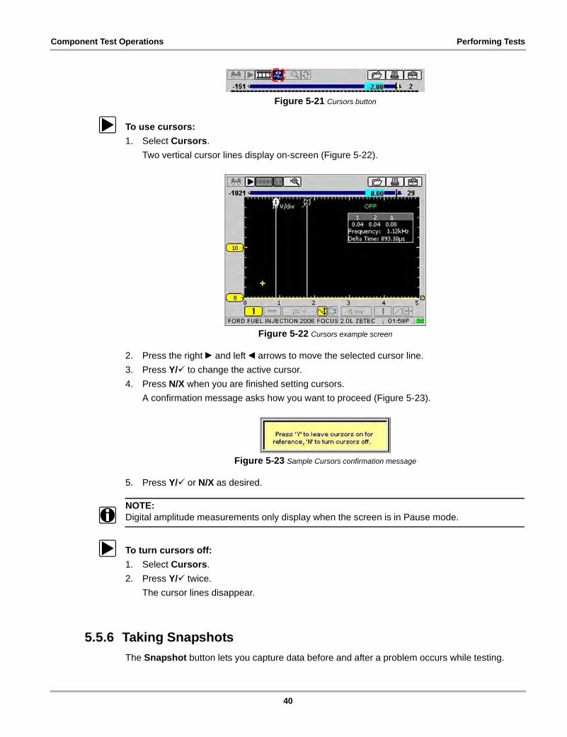
Component Test Operations Performing Tests
Figure 5-21 Cursors button
z To use cursors:
1. Select Cursors.
Two vertical cursor lines display on-screen (Figure 5-22).
Figure 5-22 Cursors example screen
2. Press the right c and left e arrows to move the selected cursor line.
3. Press Y/a to change the active cursor.
4. Press N/X when you are finished setting cursors.
A confirmation message asks how you want to proceed (Figure 5-23).
Figure 5-23 Sample Cursors confirmation message
5. Press Y/a or N/X as desired.
NOTE:i Digital amplitude measurements only display when the screen is in Pause mode.
z To turn cursors off:
1. Select Cursors.
2. Press Y/a twice.
The cursor lines disappear.
5.5.6 Taking Snapshots
The Snapshot button lets you capture data before and after a problem occurs while testing.
40
Component Test Operations Performing Tests
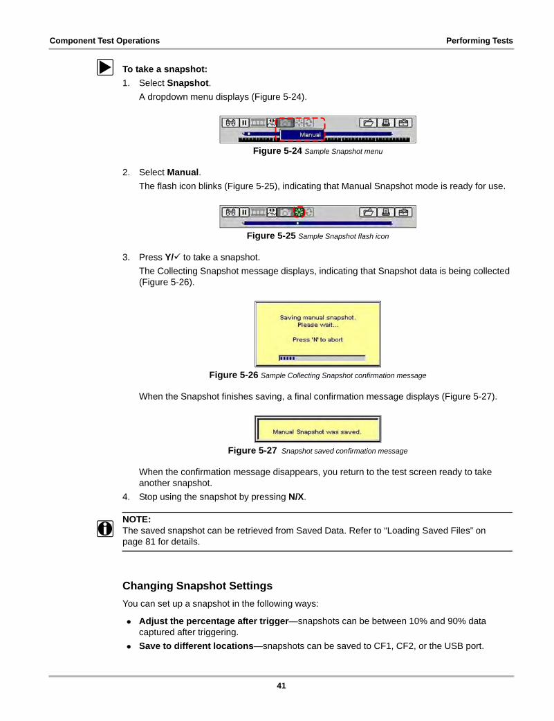
z To take a snapshot:
1. Select Snapshot.
A dropdown menu displays (Figure 5-24).
Figure 5-24 Sample Snapshot menu
2. Select Manual.
The flash icon blinks (Figure 5-25), indicating that Manual Snapshot mode is ready for use.
Figure 5-25 Sample Snapshot flash icon
3. Press Y/a to take a snapshot.
The Collecting Snapshot message displays, indicating that Snapshot data is being collected (Figure 5-26).
Figure 5-26 Sample Collecting Snapshot confirmation message
When the Snapshot finishes saving, a final confirmation message displays (Figure 5-27).
Figure 5-27 Snapshot saved confirmation message
When the confirmation message disappears, you return to the test screen ready to take another snapshot.
4. Stop using the snapshot by pressing N/X.
NOTE:i The saved snapshot can be retrieved from Saved Data. Refer to “Loading Saved Files” on
page 81 for details.
Changing Snapshot Settings
You can set up a snapshot in the following ways:
• Adjust the percentage after trigger—snapshots can be between 10% and 90% data captured after triggering.
• Save to different locations—snapshots can be saved to CF1, CF2, or the USB port.
41
Component Test Operations Performing Tests
• Choose the file type—select between bitmap and jpeg format for saving images.
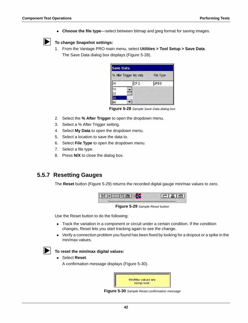
z To change Snapshot settings:
1. From the Vantage PRO main menu, select Utilities > Tool Setup > Save Data.
The Save Data dialog box displays (Figure 5-28).
Figure 5-28 Sample Save Data dialog box
2. Select the % After Trigger to open the dropdown menu.
3. Select a % After Trigger setting.
4. Select My Data to open the dropdown menu.
5. Select a location to save the data to.
6. Select File Type to open the dropdown menu.
7. Select a file type.
8. Press N/X to close the dialog box.
5.5.7 Resetting Gauges
The Reset button (Figure 5-29) returns the recorded digital gauge min/max values to zero.
Figure 5-29 Sample Reset button
Use the Reset button to do the following:
• Track the variation in a component or circuit under a certain condition. If the condition changes, Reset lets you start tracking again to see the change.
• Verify a connection problem you found has been fixed by looking for a dropout or a spike in the min/max values.
z To reset the min/max digital values:
• Select Reset.
A confirmation message displays (Figure 5-30).
Figure 5-30 Sample Reset confirmation message
42
Component Test Operations Performing Tests
When the reset is complete, the confirmation message disappears.
5.5.8 Saving Data
The Save button lets you store data and presets in memory. For more information on presets, see “Using Presets” on page 74.
z To save data:
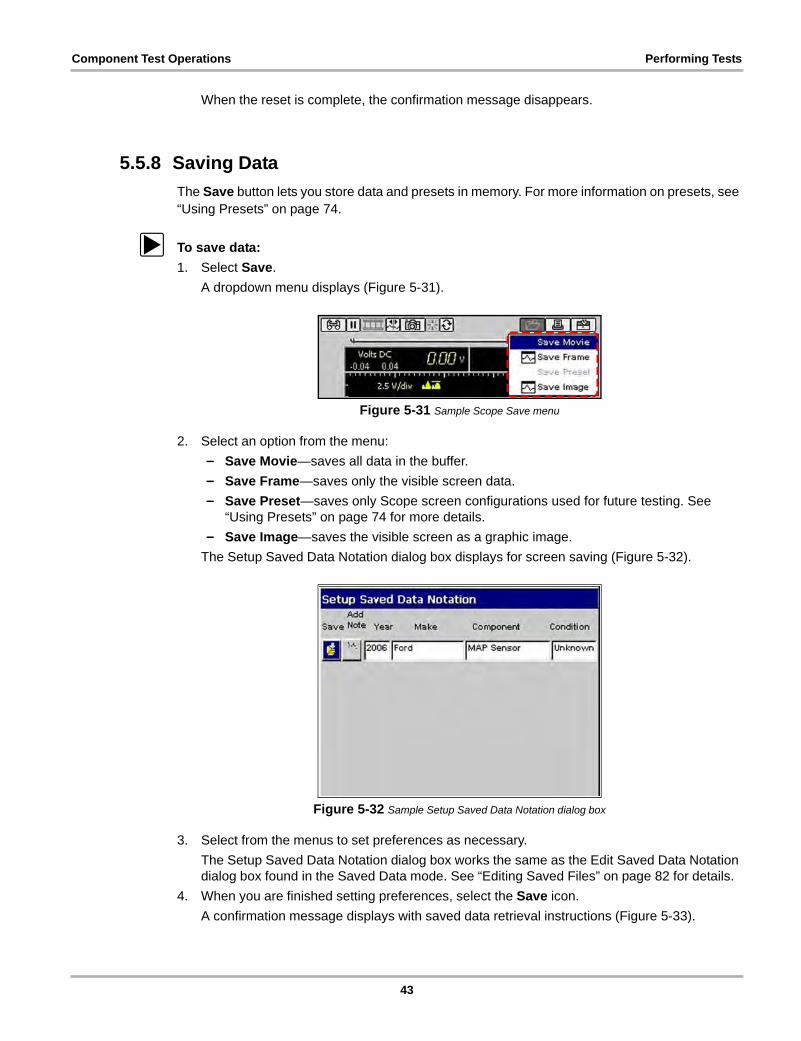
1. Select Save.
A dropdown menu displays (Figure 5-31).
Figure 5-31 Sample Scope Save menu
2. Select an option from the menu:
– Save Movie—saves all data in the buffer.
– Save Frame—saves only the visible screen data.
– Save Preset—saves only Scope screen configurations used for future testing. See “Using Presets” on page 74 for more details.
– Save Image—saves the visible screen as a graphic image.
The Setup Saved Data Notation dialog box displays for screen saving (Figure 5-32).
Figure 5-32 Sample Setup Saved Data Notation dialog box
3. Select from the menus to set preferences as necessary.
The Setup Saved Data Notation dialog box works the same as the Edit Saved Data Notation dialog box found in the Saved Data mode. See “Editing Saved Files” on page 82 for details.
4. When you are finished setting preferences, select the Save icon.
A confirmation message displays with saved data retrieval instructions (Figure 5-33).
43
Component Test Operations Performing Tests
Figure 5-33 Sample Data saved confirmation message
5. Press Y/a to close the confirmation message.
5.5.9 Printing
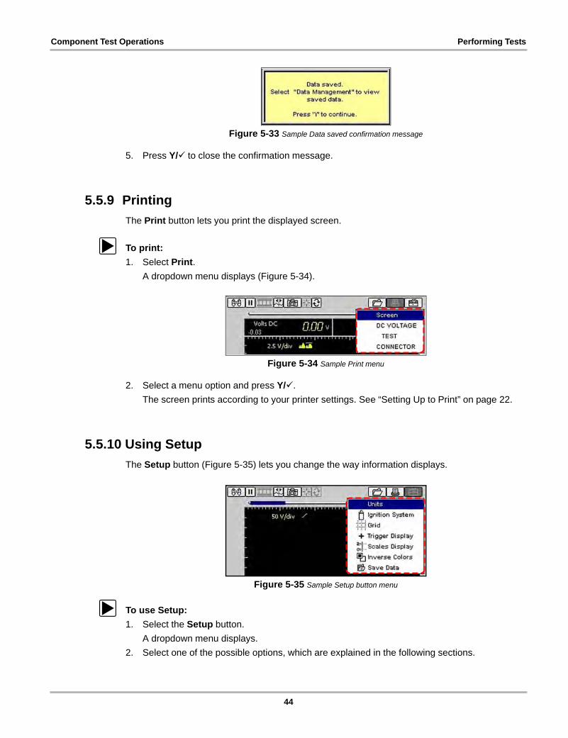
The Print button lets you print the displayed screen.
z To print:
1. Select Print.
A dropdown menu displays (Figure 5-34).
Figure 5-34 Sample Print menu
2. Select a menu option and press Y/a.
The screen prints according to your printer settings. See “Setting Up to Print” on page 22.
5.5.10 Using Setup
The Setup button (Figure 5-35) lets you change the way information displays.
Figure 5-35 Sample Setup button menu
z To use Setup:
1. Select the Setup button.
A dropdown menu displays.
2. Select one of the possible options, which are explained in the following sections.
44
Component Test Operations Performing Tests
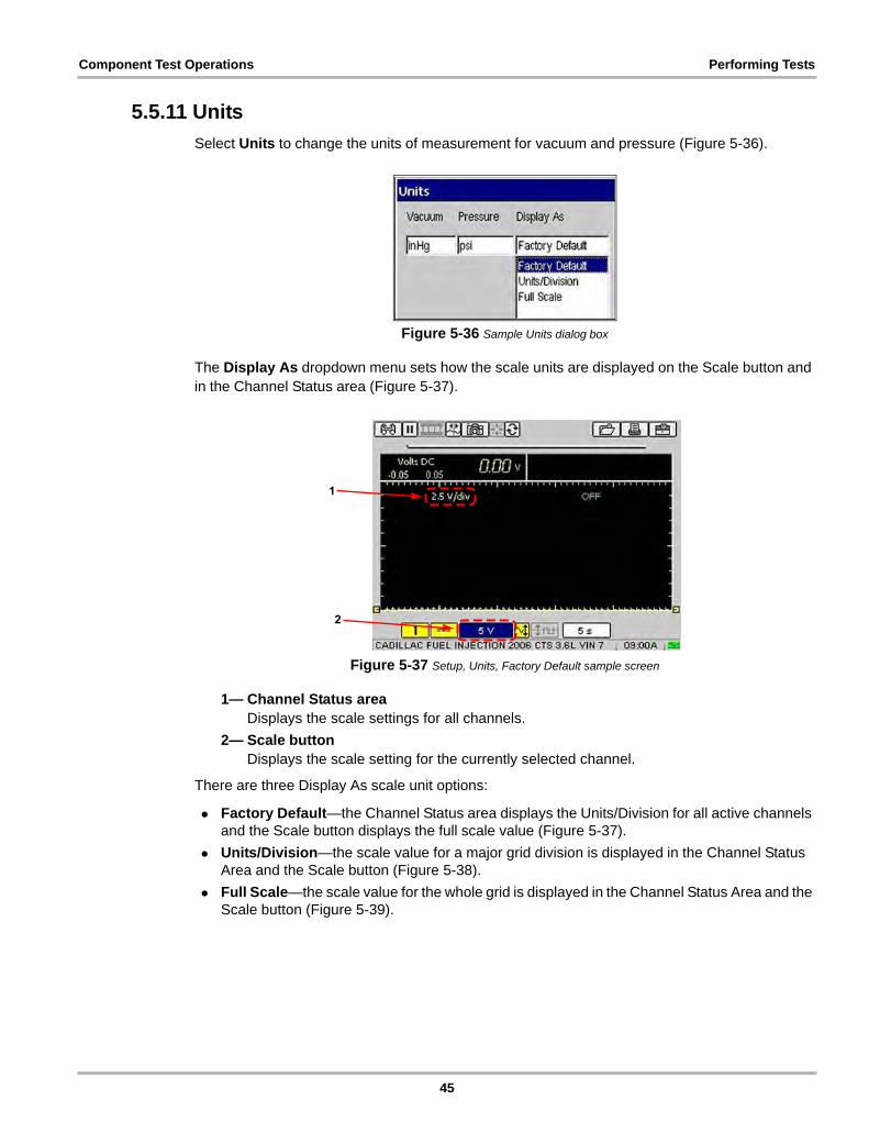
5.5.11 Units
Select Units to change the units of measurement for vacuum and pressure (Figure 5-36).
Figure 5-36 Sample Units dialog box
The Display As dropdown menu sets how the scale units are displayed on the Scale button and in the Channel Status area (Figure 5-37).
Figure 5-37 Setup, Units, Factory Default sample screen
1— Channel Status areaDisplays the scale settings for all channels.
2— Scale buttonDisplays the scale setting for the currently selected channel.
There are three Display As scale unit options:
• Factory Default—the Channel Status area displays the Units/Division for all active channels and the Scale button displays the full scale value (Figure 5-37).
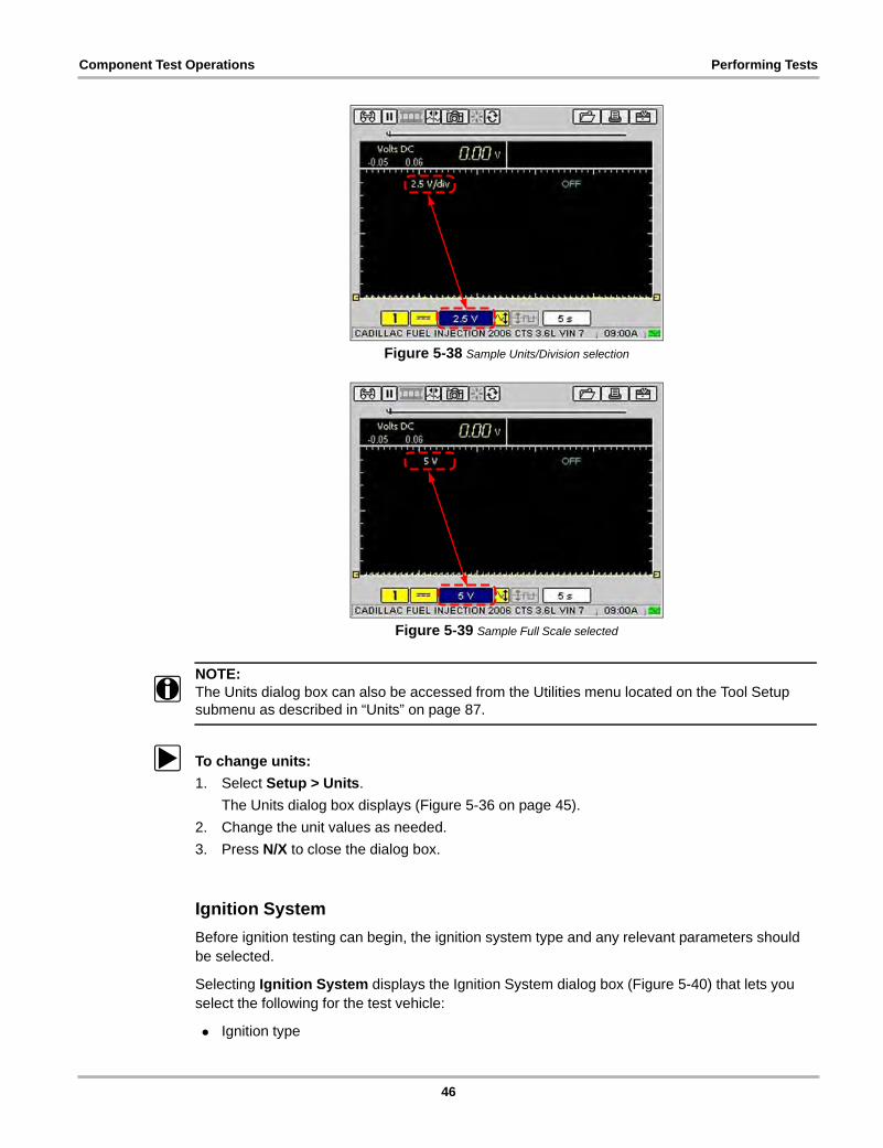
• Units/Division—the scale value for a major grid division is displayed in the Channel Status Area and the Scale button (Figure 5-38).
• Full Scale—the scale value for the whole grid is displayed in the Channel Status Area and the Scale button (Figure 5-39).
45
Component Test Operations Performing Tests
Figure 5-38 Sample Units/Division selection
Figure 5-39 Sample Full Scale selected
NOTE:i The Units dialog box can also be accessed from the Utilities menu located on the Tool Setup
submenu as described in “Units” on page 87.
z To change units:
1. Select Setup > Units.
The Units dialog box displays (Figure 5-36 on page 45).
2. Change the unit values as needed.
3. Press N/X to close the dialog box.
Ignition System
Before ignition testing can begin, the ignition system type and any relevant parameters should be selected.
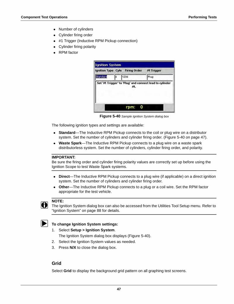
Selecting Ignition System displays the Ignition System dialog box (Figure 5-40) that lets you select the following for the test vehicle:
• Ignition type
46
Component Test Operations Performing Tests
• Number of cylinders
• Cylinder firing order
• #1 Trigger (Inductive RPM Pickup connection)
• Cylinder firing polarity
• RPM factor
Figure 5-40 Sample Ignition System dialog box
The following ignition types and settings are available:
• Standard—The Inductive RPM Pickup connects to the coil or plug wire on a distributor system. Set the number of cylinders and cylinder firing order. (Figure 5-40 on page 47).
• Waste Spark—The Inductive RPM Pickup connects to a plug wire on a waste spark distributorless system. Set the number of cylinders, cylinder firing order, and polarity.
IMPORTANT:Be sure the firing order and cylinder firing polarity values are correctly set up before using the Ignition Scope to test Waste Spark systems.
• Direct—The Inductive RPM Pickup connects to a plug wire (if applicable) on a direct ignition system. Set the number of cylinders and cylinder firing order.
• Other—The Inductive RPM Pickup connects to a plug or a coil wire. Set the RPM factor appropriate for the test vehicle.
NOTE:i The Ignition System dialog box can also be accessed from the Utilities Tool Setup menu. Refer to
“Ignition System” on page 88 for details.
z To change Ignition System settings:
1. Select Setup > Ignition System.
The Ignition System dialog box displays (Figure 5-40).
2. Select the Ignition System values as needed.
3. Press N/X to close the dialog box.
Grid
Select Grid to display the background grid pattern on all graphing test screens.
47
Component Test Operations Performing Tests
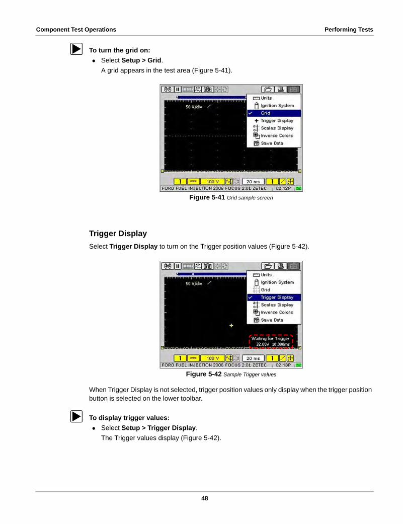
z To turn the grid on:
• Select Setup > Grid.
A grid appears in the test area (Figure 5-41).
Figure 5-41 Grid sample screen
Trigger Display
Select Trigger Display to turn on the Trigger position values (Figure 5-42).
Figure 5-42 Sample Trigger values
When Trigger Display is not selected, trigger position values only display when the trigger position button is selected on the lower toolbar.
z To display trigger values:
• Select Setup > Trigger Display.
The Trigger values display (Figure 5-42).
48
Component Test Operations Performing Tests
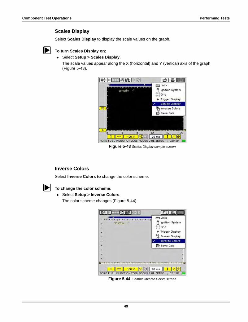
Scales Display
Select Scales Display to display the scale values on the graph.
z To turn Scales Display on:
• Select Setup > Scales Display.
The scale values appear along the X (horizontal) and Y (vertical) axis of the graph (Figure 5-43).
Figure 5-43 Scales Display sample screen
Inverse Colors
Select Inverse Colors to change the color scheme.
z To change the color scheme:
• Select Setup > Inverse Colors.
The color scheme changes (Figure 5-44).
Figure 5-44 Sample Inverse Colors screen
49
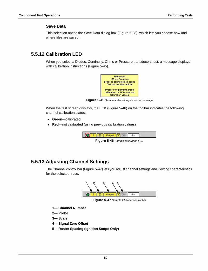
Component Test Operations Performing Tests
Save Data
This selection opens the Save Data dialog box (Figure 5-28), which lets you choose how and where files are saved.
5.5.12 Calibration LED
When you select a Diodes, Continuity, Ohms or Pressure transducers test, a message displays with calibration instructions (Figure 5-45).
Figure 5-45 Sample calibration procedure message
When the test screen displays, the LED (Figure 5-46) on the toolbar indicates the following channel calibration status:
• Green—calibrated
• Red—not calibrated (using previous calibration values)
Figure 5-46 Sample calibration LED
5.5.13 Adjusting Channel Settings
The Channel control bar (Figure 5-47) lets you adjust channel settings and viewing characteristics for the selected trace.
Figure 5-47 Sample Channel control bar
1— Channel Number
2— Probe
3— Scale
4— Signal Zero Offset
5— Raster Spacing (Ignition Scope Only)
50
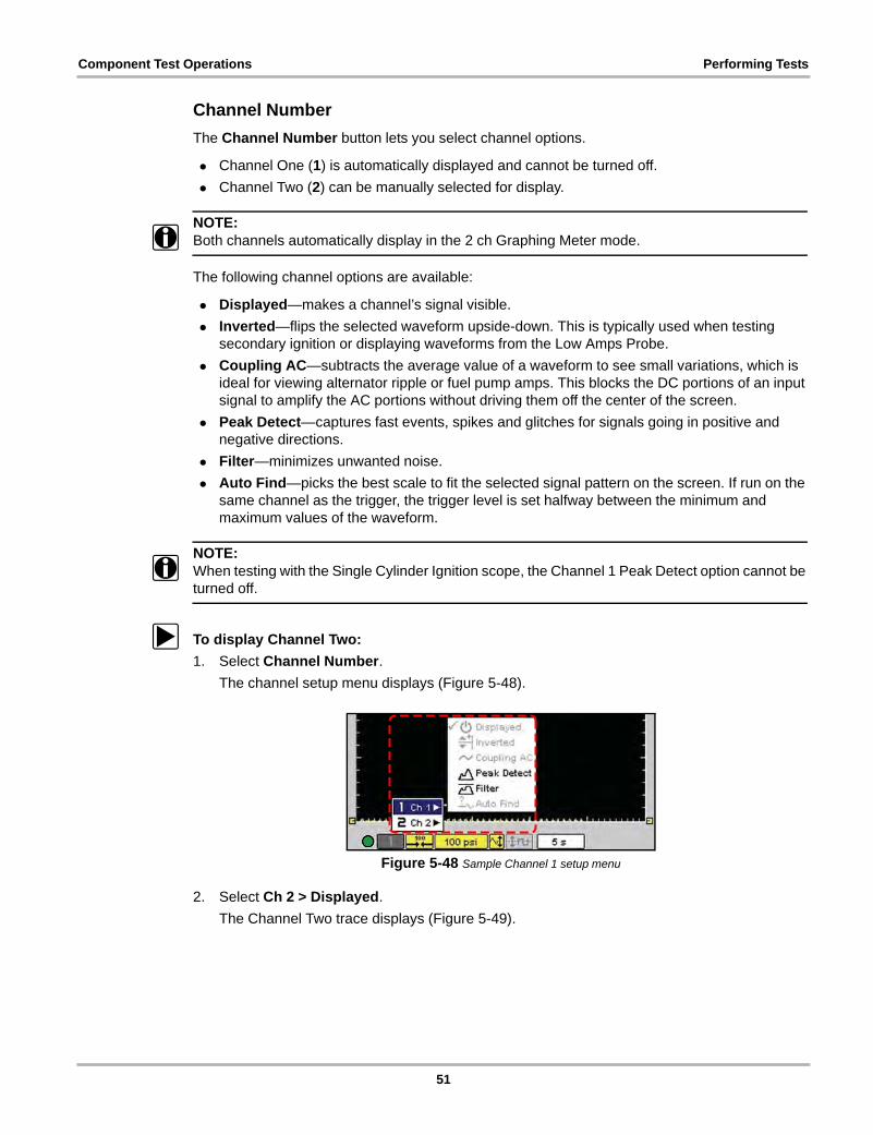
Component Test Operations Performing Tests
Channel Number
The Channel Number button lets you select channel options.
• Channel One (1) is automatically displayed and cannot be turned off.
• Channel Two (2) can be manually selected for display.
NOTE:i Both channels automatically display in the 2 ch Graphing Meter mode.
The following channel options are available:
• Displayed—makes a channel’s signal visible.
• Inverted—flips the selected waveform upside-down. This is typically used when testing secondary ignition or displaying waveforms from the Low Amps Probe.
• Coupling AC—subtracts the average value of a waveform to see small variations, which is ideal for viewing alternator ripple or fuel pump amps. This blocks the DC portions of an input signal to amplify the AC portions without driving them off the center of the screen.
• Peak Detect—captures fast events, spikes and glitches for signals going in positive and negative directions.
• Filter—minimizes unwanted noise.
• Auto Find—picks the best scale to fit the selected signal pattern on the screen. If run on the same channel as the trigger, the trigger level is set halfway between the minimum and maximum values of the waveform.
NOTE:i When testing with the Single Cylinder Ignition scope, the Channel 1 Peak Detect option cannot be
turned off.
z To display Channel Two:
1. Select Channel Number.
The channel setup menu displays (Figure 5-48).
Figure 5-48 Sample Channel 1 setup menu
2. Select Ch 2 > Displayed.
The Channel Two trace displays (Figure 5-49).
51
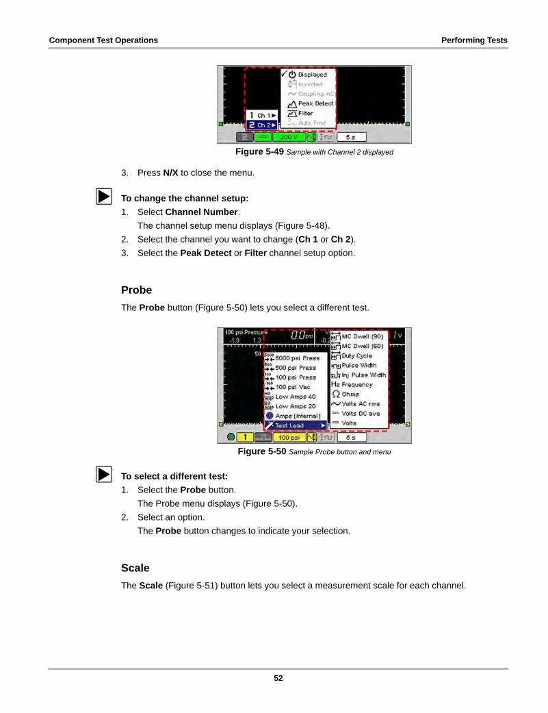
Component Test Operations Performing Tests
Figure 5-49 Sample with Channel 2 displayed
3. Press N/X to close the menu.
z To change the channel setup:
1. Select Channel Number.
The channel setup menu displays (Figure 5-48).
2. Select the channel you want to change (Ch 1 or Ch 2).
3. Select the Peak Detect or Filter channel setup option.
Probe
The Probe button (Figure 5-50) lets you select a different test.
Figure 5-50 Sample Probe button and menu
z To select a different test:
1. Select the Probe button.
The Probe menu displays (Figure 5-50).
2. Select an option.
The Probe button changes to indicate your selection.
Scale
The Scale (Figure 5-51) button lets you select a measurement scale for each channel.
52
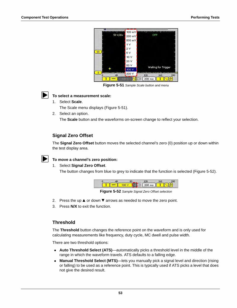
Component Test Operations Performing Tests
Figure 5-51 Sample Scale button and menu
z To select a measurement scale:
1. Select Scale.
The Scale menu displays (Figure 5-51).
2. Select an option.
The Scale button and the waveforms on-screen change to reflect your selection.
Signal Zero Offset
The Signal Zero Offset button moves the selected channel’s zero (0) position up or down within the test display area.
z To move a channel’s zero position:
1. Select Signal Zero Offset.
The button changes from blue to grey to indicate that the function is selected (Figure 5-52).
Figure 5-52 Sample Signal Zero Offset selection
2. Press the up b or down d arrows as needed to move the zero point.
3. Press N/X to exit the function.
Threshold
The Threshold button changes the reference point on the waveform and is only used for calculating measurements like frequency, duty cycle, MC dwell and pulse width.
There are two threshold options:
• Auto Threshold Select (ATS)—automatically picks a threshold level in the middle of the range in which the waveform travels. ATS defaults to a falling edge.
• Manual Threshold Select (MTS)—lets you manually pick a signal level and direction (rising or falling) to be used as a reference point. This is typically used if ATS picks a level that does not give the desired result.
53
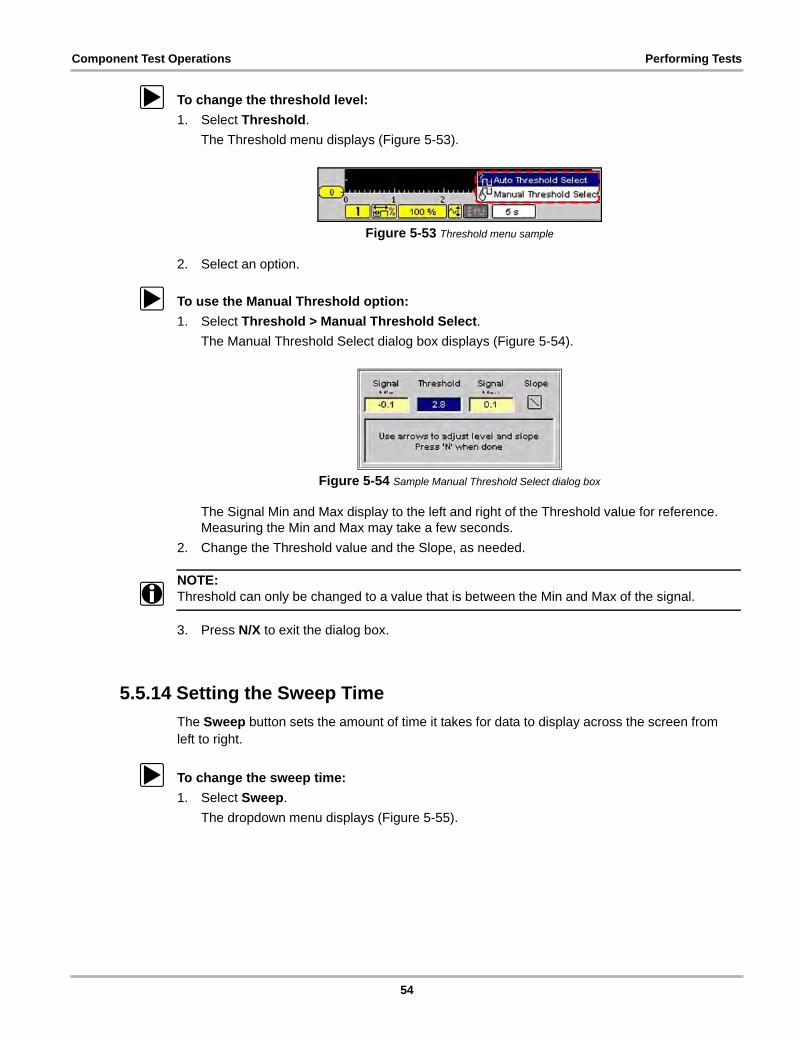
Component Test Operations Performing Tests
z To change the threshold level:
1. Select Threshold.
The Threshold menu displays (Figure 5-53).
Figure 5-53 Threshold menu sample
2. Select an option.
z To use the Manual Threshold option:
1. Select Threshold > Manual Threshold Select.
The Manual Threshold Select dialog box displays (Figure 5-54).
Figure 5-54 Sample Manual Threshold Select dialog box
The Signal Min and Max display to the left and right of the Threshold value for reference. Measuring the Min and Max may take a few seconds.
2. Change the Threshold value and the Slope, as needed.
NOTE:i Threshold can only be changed to a value that is between the Min and Max of the signal.
3. Press N/X to exit the dialog box.
5.5.14 Setting the Sweep Time
The Sweep button sets the amount of time it takes for data to display across the screen from left to right.
z To change the sweep time:
1. Select Sweep.
The dropdown menu displays (Figure 5-55).
54
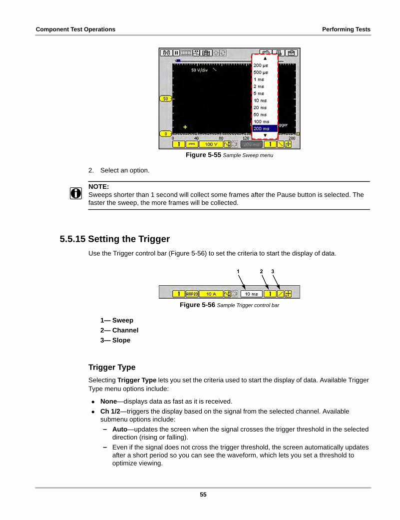
Component Test Operations Performing Tests
Figure 5-55 Sample Sweep menu
2. Select an option.
NOTE:i Sweeps shorter than 1 second will collect some frames after the Pause button is selected. The
faster the sweep, the more frames will be collected.
5.5.15 Setting the Trigger
Use the Trigger control bar (Figure 5-56) to set the criteria to start the display of data.
Figure 5-56 Sample Trigger control bar
1— Sweep
2— Channel
3— Slope
Trigger Type
Selecting Trigger Type lets you set the criteria used to start the display of data. Available Trigger Type menu options include:
• None—displays data as fast as it is received.
• Ch 1/2—triggers the display based on the signal from the selected channel. Available submenu options include:
– Auto—updates the screen when the signal crosses the trigger threshold in the selected direction (rising or falling).
– Even if the signal does not cross the trigger threshold, the screen automatically updates after a short period so you can see the waveform, which lets you set a threshold to optimize viewing.
55
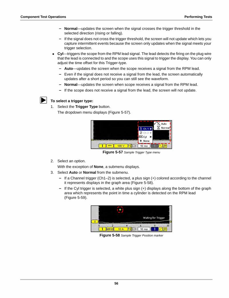
Component Test Operations Performing Tests
– Normal—updates the screen when the signal crosses the trigger threshold in the selected direction (rising or falling).
– If the signal does not cross the trigger threshold, the screen will not update which lets you capture intermittent events because the screen only updates when the signal meets your trigger selection.
• Cyl—triggers the scope from the RPM lead signal. The lead detects the firing on the plug wire that the lead is connected to and the scope uses this signal to trigger the display. You can only adjust the time offset for this Trigger-type.
– Auto—updates the screen when the scope receives a signal from the RPM lead.
– Even if the signal does not receive a signal from the lead, the screen automatically updates after a short period so you can still see the waveform.
– Normal—updates the screen when scope receives a signal from the RPM lead.
– If the scope does not receive a signal from the lead, the screen will not update.
z To select a trigger type:
1. Select the Trigger Type button.
The dropdown menu displays (Figure 5-57).
Figure 5-57 Sample Trigger Type menu
2. Select an option.
With the exception of None, a submenu displays.
3. Select Auto or Normal from the submenu.
– If a Channel trigger (Ch1–2) is selected, a plus sign (+) colored according to the channel it represents displays in the graph area (Figure 5-58).
– If the Cyl trigger is selected, a white plus sign (+) displays along the bottom of the graph area which represents the point in time a cylinder is detected on the RPM lead (Figure 5-59).
Figure 5-58 Sample Trigger Position marker
56
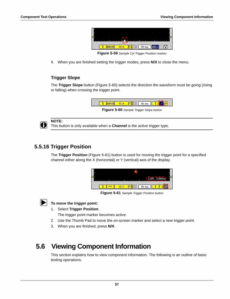
Component Test Operations Viewing Component Information
Figure 5-59 Sample Cyl Trigger Position marker
4. When you are finished setting the trigger modes, press N/X to close the menu.
Trigger Slope
The Trigger Slope button (Figure 5-60) selects the direction the waveform must be going (rising or falling) when crossing the trigger point.
Figure 5-60 Sample Trigger Slope button
NOTE:i This button is only available when a Channel is the active trigger type.
5.5.16 Trigger Position
The Trigger Position (Figure 5-61) button is used for moving the trigger point for a specified channel either along the X (horizontal) or Y (vertical) axis of the display.
Figure 5-61 Sample Trigger Position button
z To move the trigger point:
1. Select Trigger Position.
The trigger point marker becomes active.
2. Use the Thumb Pad to move the on-screen marker and select a new trigger point.
3. When you are finished, press N/X.
5.6 Viewing Component InformationThis section explains how to view component information. The following is an outline of basic testing operations.
57
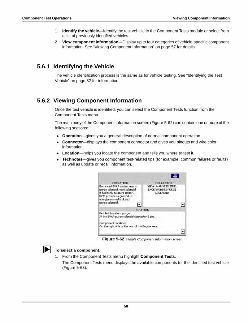
Component Test Operations Viewing Component Information
1. Identify the vehicle—Identify the test vehicle to the Component Tests module or select from a list of previously identified vehicles.
2. View component information—Display up to four categories of vehicle-specific component information. See “Viewing Component Information” on page 57 for details.
5.6.1 Identifying the Vehicle
The vehicle identification process is the same as for vehicle testing. See “Identifying the Test Vehicle” on page 32 for information.
5.6.2 Viewing Component Information
Once the test vehicle is identified, you can select the Component Tests function from the Component Tests menu.
The main body of the Component Information screen (Figure 5-62) can contain one or more of the following sections:
• Operation—gives you a general description of normal component operation.
• Connector—displays the component connector and gives you pinouts and wire color information.
• Location—helps you locate the component and tells you where to test it.
• Technotes—gives you component test-related tips (for example, common failures or faults) as well as update or recall information.
Figure 5-62 Sample Component Information screen
z To select a component:
1. From the Component Tests menu highlight Component Tests.
The Component Tests menu displays the available components for the identified test vehicle (Figure 5-63).
58
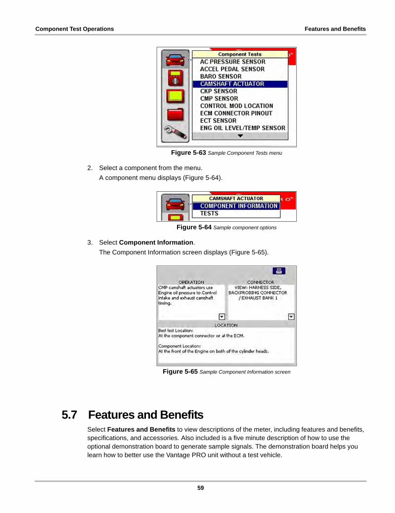
Component Test Operations Features and Benefits
Figure 5-63 Sample Component Tests menu
2. Select a component from the menu.
A component menu displays (Figure 5-64).
Figure 5-64 Sample component options
3. Select Component Information.
The Component Information screen displays (Figure 5-65).
Figure 5-65 Sample Component Information screen
5.7 Features and BenefitsSelect Features and Benefits to view descriptions of the meter, including features and benefits, specifications, and accessories. Also included is a five minute description of how to use the optional demonstration board to generate sample signals. The demonstration board helps you learn how to better use the Vantage PRO unit without a test vehicle.
59
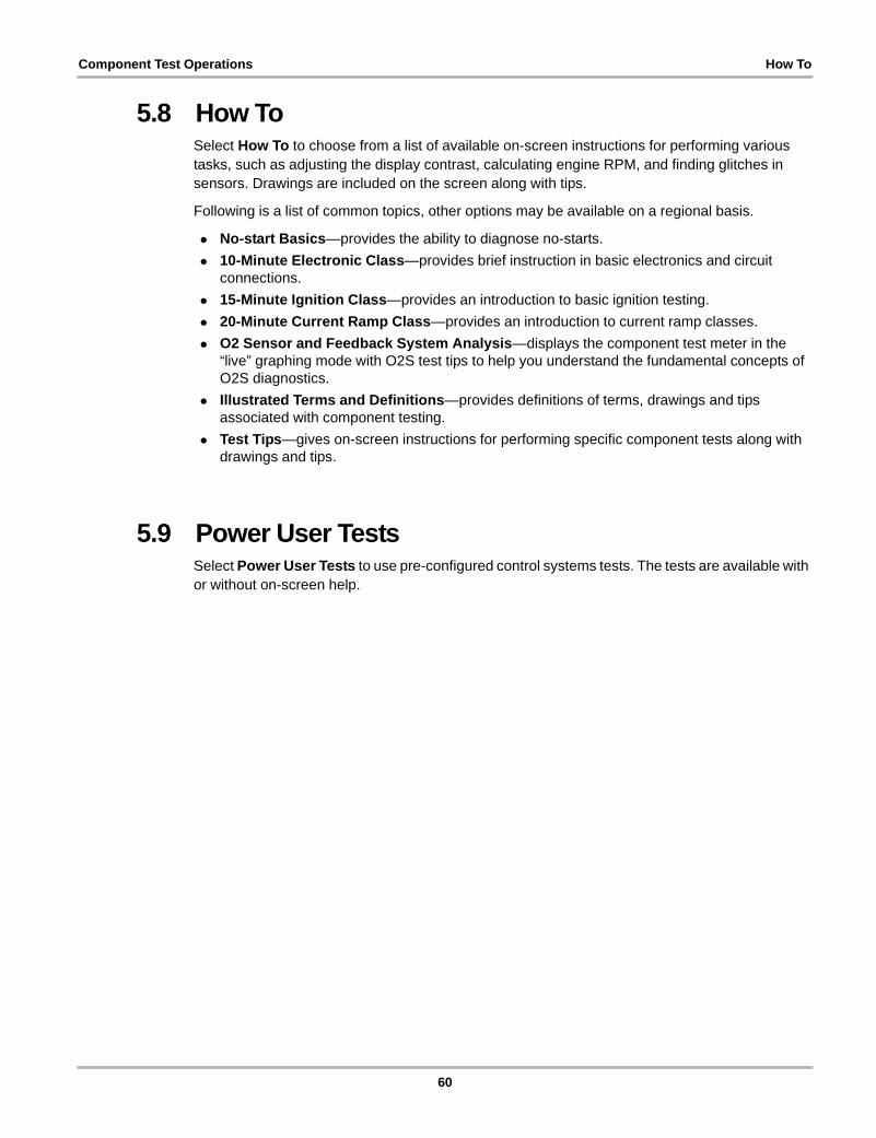
Component Test Operations How To
5.8 How ToSelect How To to choose from a list of available on-screen instructions for performing various tasks, such as adjusting the display contrast, calculating engine RPM, and finding glitches in sensors. Drawings are included on the screen along with tips.
Following is a list of common topics, other options may be available on a regional basis.
• No-start Basics—provides the ability to diagnose no-starts.
• 10-Minute Electronic Class—provides brief instruction in basic electronics and circuit connections.
• 15-Minute Ignition Class—provides an introduction to basic ignition testing.
• 20-Minute Current Ramp Class—provides an introduction to current ramp classes.
• O2 Sensor and Feedback System Analysis—displays the component test meter in the “live” graphing mode with O2S test tips to help you understand the fundamental concepts of O2S diagnostics.
• Illustrated Terms and Definitions—provides definitions of terms, drawings and tips associated with component testing.
• Test Tips—gives on-screen instructions for performing specific component tests along with drawings and tips.
5.9 Power User TestsSelect Power User Tests to use pre-configured control systems tests. The tests are available with or without on-screen help.
60
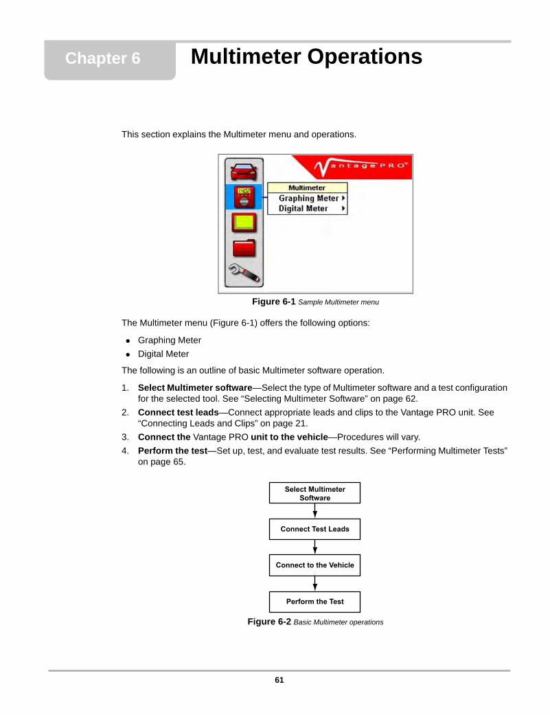
Chapter 6 Multimeter Operations
This section explains the Multimeter menu and operations.
Figure 6-1 Sample Multimeter menu
The Multimeter menu (Figure 6-1) offers the following options:
• Graphing Meter
• Digital Meter
The following is an outline of basic Multimeter software operation.
1. Select Multimeter software—Select the type of Multimeter software and a test configuration for the selected tool. See “Selecting Multimeter Software” on page 62.
2. Connect test leads—Connect appropriate leads and clips to the Vantage PRO unit. See “Connecting Leads and Clips” on page 21.
3. Connect the Vantage PRO unit to the vehicle—Procedures will vary.
4. Perform the test—Set up, test, and evaluate test results. See “Performing Multimeter Tests” on page 65.
Figure 6-2 Basic Multimeter operations
Select MultimeterSoftware
Connect Test Leads
Connect to the Vehicle
Perform the Test
61
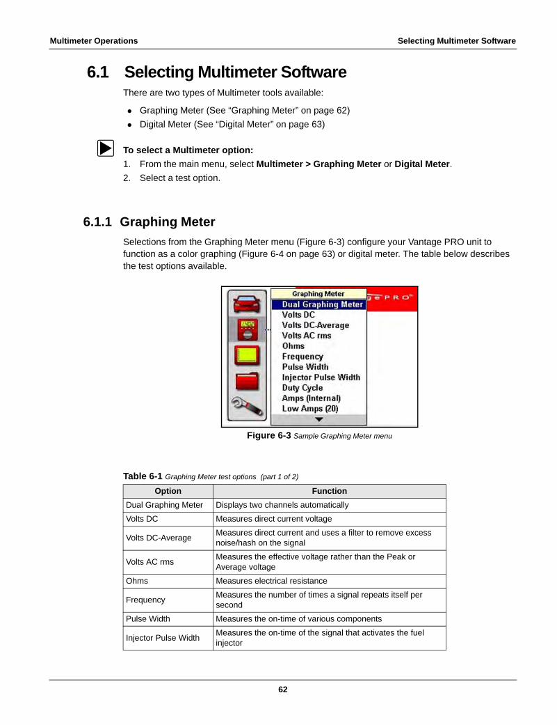
Multimeter Operations Selecting Multimeter Software
6.1 Selecting Multimeter SoftwareThere are two types of Multimeter tools available:
• Graphing Meter (See “Graphing Meter” on page 62)
• Digital Meter (See “Digital Meter” on page 63)
z To select a Multimeter option:
1. From the main menu, select Multimeter > Graphing Meter or Digital Meter.
2. Select a test option.
6.1.1 Graphing Meter
Selections from the Graphing Meter menu (Figure 6-3) configure your Vantage PRO unit to function as a color graphing (Figure 6-4 on page 63) or digital meter. The table below describes the test options available.
Figure 6-3 Sample Graphing Meter menu
Table 6-1 Graphing Meter test options (part 1 of 2)
Option Function
Dual Graphing Meter Displays two channels automatically
Volts DC Measures direct current voltage
Volts DC-AverageMeasures direct current and uses a filter to remove excess noise/hash on the signal
Volts AC rmsMeasures the effective voltage rather than the Peak or Average voltage
Ohms Measures electrical resistance
FrequencyMeasures the number of times a signal repeats itself per second
Pulse Width Measures the on-time of various components
Injector Pulse WidthMeasures the on-time of the signal that activates the fuel injector
62
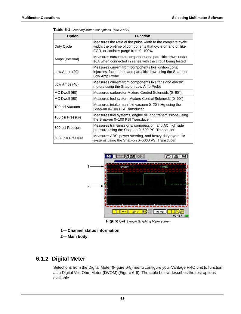
Multimeter Operations Selecting Multimeter Software
Figure 6-4 Sample Graphing Meter screen
1— Channel status information
2— Main body
6.1.2 Digital Meter
Selections from the Digital Meter (Figure 6-5) menu configure your Vantage PRO unit to function as a Digital Volt Ohm Meter (DVOM) (Figure 6-6). The table below describes the test options available.
Duty CycleMeasures the ratio of the pulse width to the complete cycle width, the on-time of components that cycle on and off like EGR, or canister purge from 0–100%
Amps (Internal)Measures current for component and parasitic draws under 10A when connected in series with the circuit being tested
Low Amps (20)Measures current from components like ignition coils, injectors, fuel pumps and parasitic draw using the Snap-on Low Amp Probe
Low Amps (40)Measures current from components like fans and electric motors using the Snap-on Low Amp Probe
MC Dwell (60) Measures carburetor Mixture Control Solenoids (0–60°)
MC Dwell (90) Measures fuel system Mixture Control Solenoids (0–90°)
100 psi VacuumMeasures intake manifold vacuum 0–20 inHg using the Snap-on 0–100 PSI Transducer
100 psi PressureMeasures fuel systems, engine oil, and transmissions using the Snap-on 0–100 PSI Transducer
500 psi PressureMeasures transmissions, compression, and AC high side pressure using the Snap-on 0–500 PSI Transducer
5000 psi PressureMeasures ABS, power steering, and heavy-duty hydraulic systems using the Snap-on 0–5000 PSI Transducer
Table 6-1 Graphing Meter test options (part 2 of 2)
Option Function
63
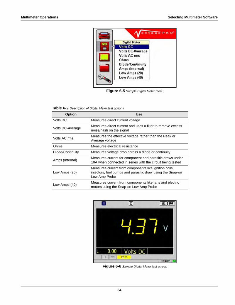
Multimeter Operations Selecting Multimeter Software
Figure 6-5 Sample Digital Meter menu
Figure 6-6 Sample Digital Meter test screen
Table 6-2 Description of Digital Meter test options
Option Use
Volts DC Measures direct current voltage
Volts DC-AverageMeasures direct current and uses a filter to remove excess noise/hash on the signal
Volts AC rmsMeasures the effective voltage rather than the Peak or Average voltage
Ohms Measures electrical resistance
Diode/Continuity Measures voltage drop across a diode or continuity
Amps (Internal)Measures current for component and parasitic draws under 10A when connected in series with the circuit being tested
Low Amps (20)Measures current from components like ignition coils, injectors, fuel pumps and parasitic draw using the Snap-on Low Amp Probe
Low Amps (40)Measures current from components like fans and electric motors using the Snap-on Low Amp Probe
64
Multimeter Operations Performing Multimeter Tests
6.2 Performing Multimeter TestsWhen performing tests with the Multimeter, the toolbars and controls work the same as those in Component Tests. Button and menu option availability vary depending on your test selection.
For related information, see the following Component Tests Operations sections:
• See “Changing Views” on page 36
• See “Pausing Data” on page 37
• See “Reviewing Data” on page 38
• See “Using Zoom” on page 38
• See “Using Cursors” on page 39
• See “Taking Snapshots” on page 40
• See “Resetting Gauges” on page 42
• See “Saving Data” on page 43
• See “Printing” on page 44
• See “Using Setup” on page 44
• See “Calibration LED” on page 50
• See “Adjusting Channel Settings” on page 50
• See “Setting the Sweep Time” on page 54
• See “Setting the Trigger” on page 55
65
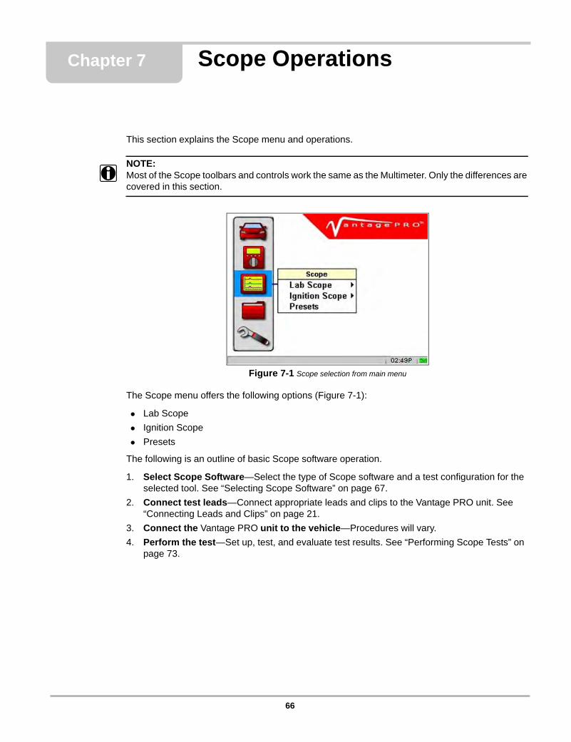
Chapter 7 Scope Operations
This section explains the Scope menu and operations.
NOTE:i Most of the Scope toolbars and controls work the same as the Multimeter. Only the differences are
covered in this section.
Figure 7-1 Scope selection from main menu
The Scope menu offers the following options (Figure 7-1):
• Lab Scope
• Ignition Scope
• Presets
The following is an outline of basic Scope software operation.
1. Select Scope Software—Select the type of Scope software and a test configuration for the selected tool. See “Selecting Scope Software” on page 67.
2. Connect test leads—Connect appropriate leads and clips to the Vantage PRO unit. See “Connecting Leads and Clips” on page 21.
3. Connect the Vantage PRO unit to the vehicle—Procedures will vary.
4. Perform the test—Set up, test, and evaluate test results. See “Performing Scope Tests” on page 73.
66
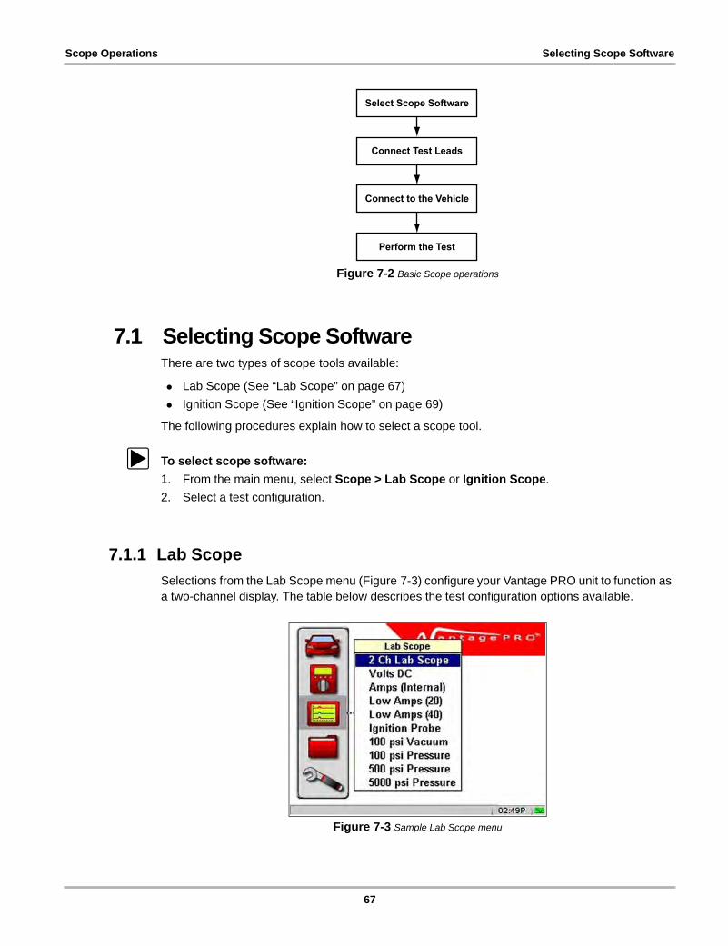
Scope Operations Selecting Scope Software
Figure 7-2 Basic Scope operations
7.1 Selecting Scope SoftwareThere are two types of scope tools available:
• Lab Scope (See “Lab Scope” on page 67)
• Ignition Scope (See “Ignition Scope” on page 69)
The following procedures explain how to select a scope tool.
z To select scope software:
1. From the main menu, select Scope > Lab Scope or Ignition Scope.
2. Select a test configuration.
7.1.1 Lab Scope
Selections from the Lab Scope menu (Figure 7-3) configure your Vantage PRO unit to function as a two-channel display. The table below describes the test configuration options available.
Figure 7-3 Sample Lab Scope menu
Select Scope Software
Connect Test Leads
Connect to the Vehicle
Perform the Test
67
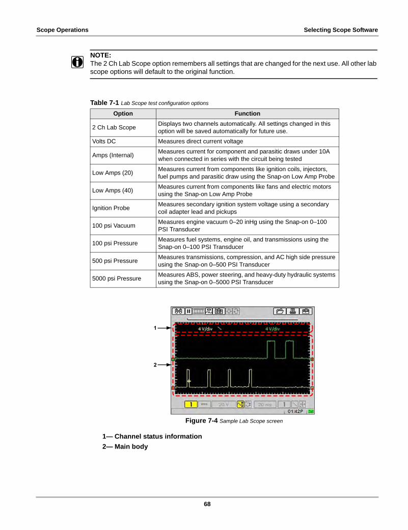
Scope Operations Selecting Scope Software
NOTE:i The 2 Ch Lab Scope option remembers all settings that are changed for the next use. All other lab
scope options will default to the original function.
Figure 7-4 Sample Lab Scope screen
1— Channel status information
2— Main body
Table 7-1 Lab Scope test configuration options
Option Function
2 Ch Lab ScopeDisplays two channels automatically. All settings changed in this option will be saved automatically for future use.
Volts DC Measures direct current voltage
Amps (Internal)Measures current for component and parasitic draws under 10A when connected in series with the circuit being tested
Low Amps (20)Measures current from components like ignition coils, injectors, fuel pumps and parasitic draw using the Snap-on Low Amp Probe
Low Amps (40)Measures current from components like fans and electric motors using the Snap-on Low Amp Probe
Ignition ProbeMeasures secondary ignition system voltage using a secondary coil adapter lead and pickups
100 psi VacuumMeasures engine vacuum 0–20 inHg using the Snap-on 0–100 PSI Transducer
100 psi PressureMeasures fuel systems, engine oil, and transmissions using the Snap-on 0–100 PSI Transducer
500 psi PressureMeasures transmissions, compression, and AC high side pressure using the Snap-on 0–500 PSI Transducer
5000 psi PressureMeasures ABS, power steering, and heavy-duty hydraulic systems using the Snap-on 0–5000 PSI Transducer
68
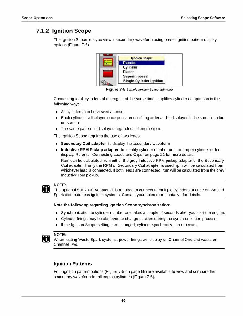
Scope Operations Selecting Scope Software
7.1.2 Ignition Scope
The Ignition Scope lets you view a secondary waveform using preset ignition pattern display options (Figure 7-5).
Figure 7-5 Sample Ignition Scope submenu
Connecting to all cylinders of an engine at the same time simplifies cylinder comparison in the following ways:
• All cylinders can be viewed at once.
• Each cylinder is displayed once per screen in firing order and is displayed in the same location on-screen.
• The same pattern is displayed regardless of engine rpm.
The Ignition Scope requires the use of two leads.
• Secondary Coil adapter–to display the secondary waveform
• Inductive RPM Pickup adapter–to identify cylinder number one for proper cylinder order display. Refer to “Connecting Leads and Clips” on page 21 for more details.
Rpm can be calculated from either the grey Inductive RPM pickup adapter or the Secondary Coil adapter. If only the RPM or Secondary Coil adapter is used, rpm will be calculated from whichever lead is connected. If both leads are connected, rpm will be calculated from the grey Inductive rpm pickup.
NOTE:i The optional SIA 2000 Adapter kit is required to connect to multiple cylinders at once on Wasted
Spark distributorless ignition systems. Contact your sales representative for details.
Note the following regarding Ignition Scope synchronization:
• Synchronization to cylinder number one takes a couple of seconds after you start the engine.
• Cylinder firings may be observed to change position during the synchronization process.
• If the Ignition Scope settings are changed, cylinder synchronization reoccurs.
NOTE:i When testing Waste Spark systems, power firings will display on Channel One and waste on
Channel Two.
Ignition Patterns
Four ignition pattern options (Figure 7-5 on page 69) are available to view and compare the secondary waveform for all engine cylinders (Figure 7-6).
69
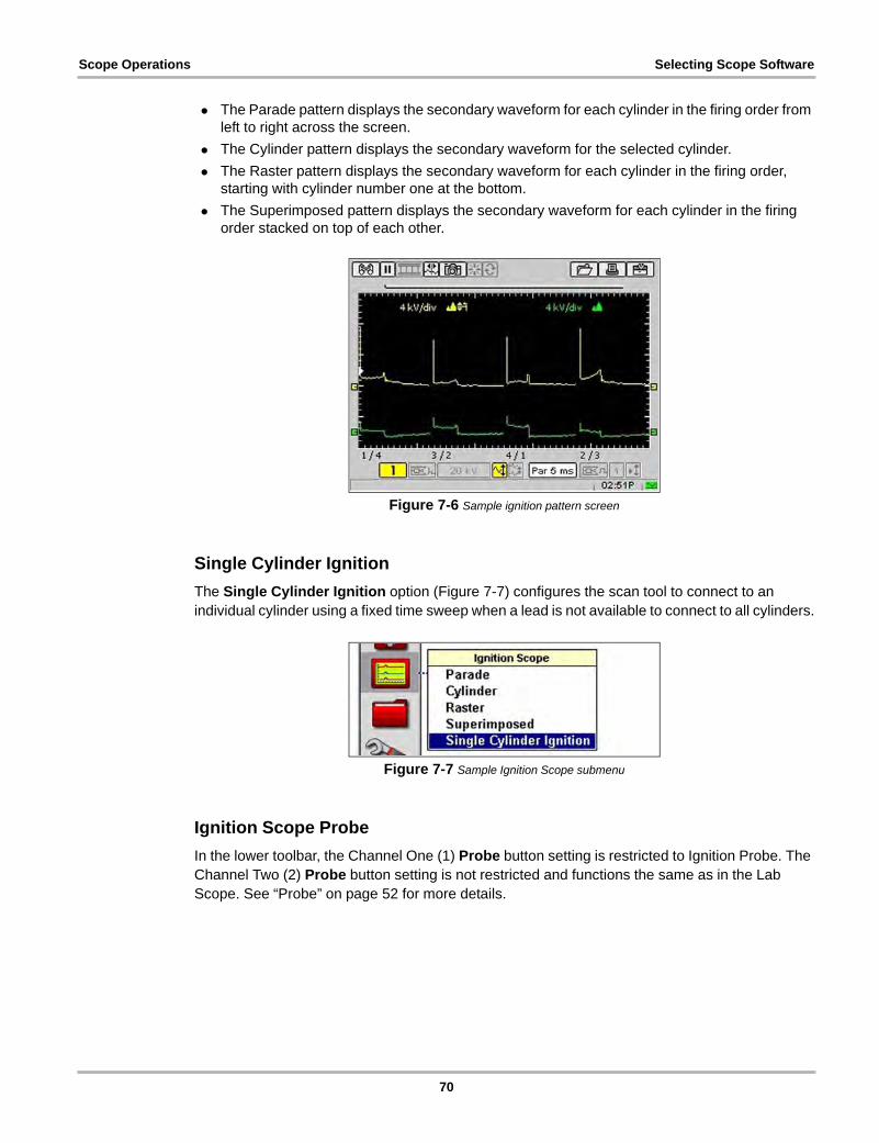
Scope Operations Selecting Scope Software
• The Parade pattern displays the secondary waveform for each cylinder in the firing order from left to right across the screen.
• The Cylinder pattern displays the secondary waveform for the selected cylinder.
• The Raster pattern displays the secondary waveform for each cylinder in the firing order, starting with cylinder number one at the bottom.
• The Superimposed pattern displays the secondary waveform for each cylinder in the firing order stacked on top of each other.
Figure 7-6 Sample ignition pattern screen
Single Cylinder Ignition
The Single Cylinder Ignition option (Figure 7-7) configures the scan tool to connect to an individual cylinder using a fixed time sweep when a lead is not available to connect to all cylinders.
Figure 7-7 Sample Ignition Scope submenu
Ignition Scope Probe
In the lower toolbar, the Channel One (1) Probe button setting is restricted to Ignition Probe. The Channel Two (2) Probe button setting is not restricted and functions the same as in the Lab Scope. See “Probe” on page 52 for more details.
70
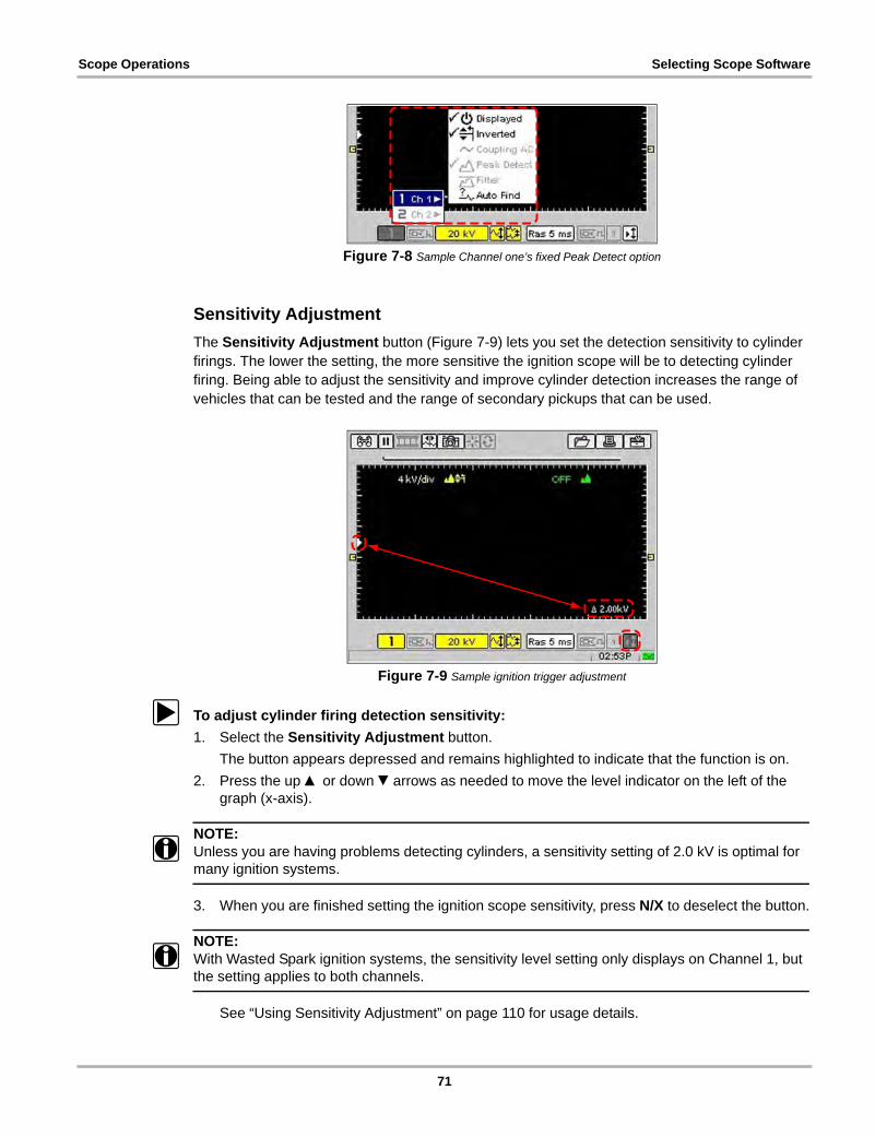
Scope Operations Selecting Scope Software
Figure 7-8 Sample Channel one’s fixed Peak Detect option
Sensitivity Adjustment
The Sensitivity Adjustment button (Figure 7-9) lets you set the detection sensitivity to cylinder firings. The lower the setting, the more sensitive the ignition scope will be to detecting cylinder firing. Being able to adjust the sensitivity and improve cylinder detection increases the range of vehicles that can be tested and the range of secondary pickups that can be used.
Figure 7-9 Sample ignition trigger adjustment
z To adjust cylinder firing detection sensitivity:
1. Select the Sensitivity Adjustment button.
The button appears depressed and remains highlighted to indicate that the function is on.
2. Press the up b or down d arrows as needed to move the level indicator on the left of the graph (x-axis).
NOTE:i Unless you are having problems detecting cylinders, a sensitivity setting of 2.0 kV is optimal for
many ignition systems.
3. When you are finished setting the ignition scope sensitivity, press N/X to deselect the button.
NOTE:i With Wasted Spark ignition systems, the sensitivity level setting only displays on Channel 1, but
the setting applies to both channels.
See “Using Sensitivity Adjustment” on page 110 for usage details.
71
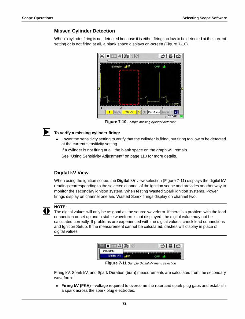
Scope Operations Selecting Scope Software
Missed Cylinder Detection
When a cylinder firing is not detected because it is either firing too low to be detected at the current setting or is not firing at all, a blank space displays on-screen (Figure 7-10).
Figure 7-10 Sample missing cylinder detection
z To verify a missing cylinder firing:
• Lower the sensitivity setting to verify that the cylinder is firing, but firing too low to be detected at the current sensitivity setting.
If a cylinder is not firing at all, the blank space on the graph will remain.
See “Using Sensitivity Adjustment” on page 110 for more details.
Digital kV View
When using the ignition scope, the Digital kV view selection (Figure 7-11) displays the digital kV readings corresponding to the selected channel of the ignition scope and provides another way to monitor the secondary ignition system. When testing Wasted Spark ignition systems, Power firings display on channel one and Wasted Spark firings display on channel two.
NOTE:i The digital values will only be as good as the source waveform. If there is a problem with the lead
connection or set up and a stable waveform is not displayed, the digital value may not be calculated correctly. If problems are experienced with the digital values, check lead connections and Ignition Setup. If the measurement cannot be calculated, dashes will display in place of digital values.
Figure 7-11 Sample Digital kV menu selection
Firing kV, Spark kV, and Spark Duration (burn) measurements are calculated from the secondary waveform.
• Firing kV (FKV)—voltage required to overcome the rotor and spark plug gaps and establish a spark across the spark plug electrodes.
72
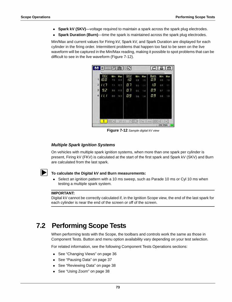
Scope Operations Performing Scope Tests
• Spark kV (SKV)—voltage required to maintain a spark across the spark plug electrodes.
• Spark Duration (Burn)—time the spark is maintained across the spark plug electrodes.
Min/Max and current values for Firing kV, Spark kV, and Spark Duration are displayed for each cylinder in the firing order. Intermittent problems that happen too fast to be seen on the live waveform will be captured in the Min/Max reading, making it possible to spot problems that can be difficult to see in the live waveform (Figure 7-12).
Figure 7-12 Sample digital kV view
Multiple Spark Ignition Systems
On vehicles with multiple spark ignition systems, when more than one spark per cylinder is present, Firing kV (FKV) is calculated at the start of the first spark and Spark kV (SKV) and Burn are calculated from the last spark.
z To calculate the Digital kV and Burn measurements:
• Select an ignition pattern with a 10 ms sweep, such as Parade 10 ms or Cyl 10 ms when testing a multiple spark system.
IMPORTANT:Digital kV cannot be correctly calculated if, in the Ignition Scope view, the end of the last spark for each cylinder is near the end of the screen or off of the screen.
7.2 Performing Scope TestsWhen performing tests with the Scope, the toolbars and controls work the same as those in Component Tests. Button and menu option availability vary depending on your test selection.
For related information, see the following Component Tests Operations sections:
• See “Changing Views” on page 36
• See “Pausing Data” on page 37
• See “Reviewing Data” on page 38
• See “Using Zoom” on page 38
73
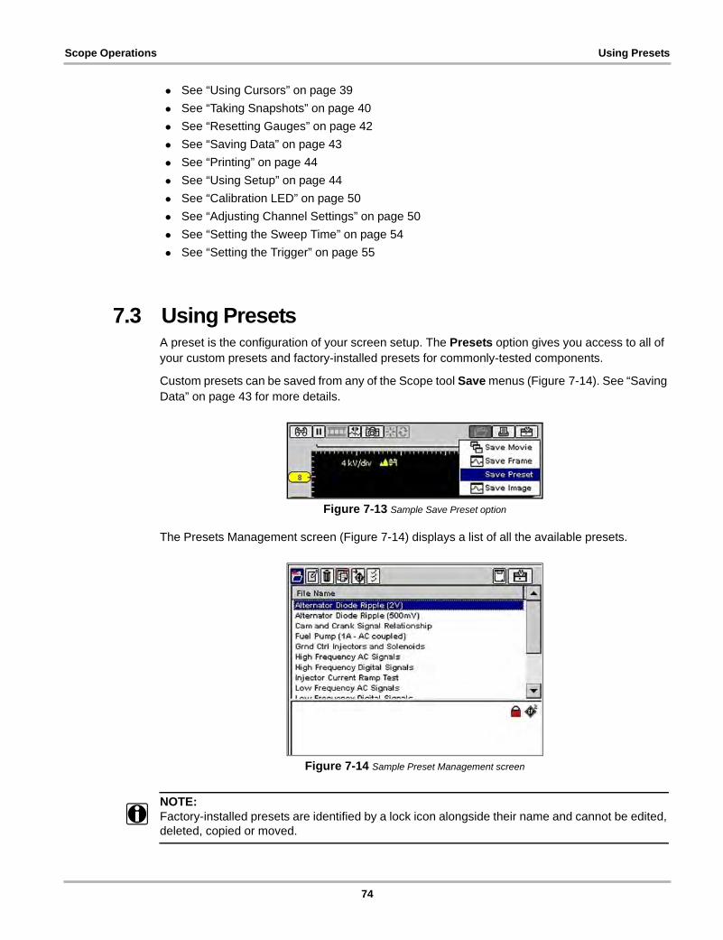
Scope Operations Using Presets
• See “Using Cursors” on page 39
• See “Taking Snapshots” on page 40
• See “Resetting Gauges” on page 42
• See “Saving Data” on page 43
• See “Printing” on page 44
• See “Using Setup” on page 44
• See “Calibration LED” on page 50
• See “Adjusting Channel Settings” on page 50
• See “Setting the Sweep Time” on page 54
• See “Setting the Trigger” on page 55
7.3 Using PresetsA preset is the configuration of your screen setup. The Presets option gives you access to all of your custom presets and factory-installed presets for commonly-tested components.
Custom presets can be saved from any of the Scope tool Save menus (Figure 7-14). See “Saving Data” on page 43 for more details.
Figure 7-13 Sample Save Preset option
The Presets Management screen (Figure 7-14) displays a list of all the available presets.
Figure 7-14 Sample Preset Management screen
NOTE:i Factory-installed presets are identified by a lock icon alongside their name and cannot be edited,
deleted, copied or moved.
74
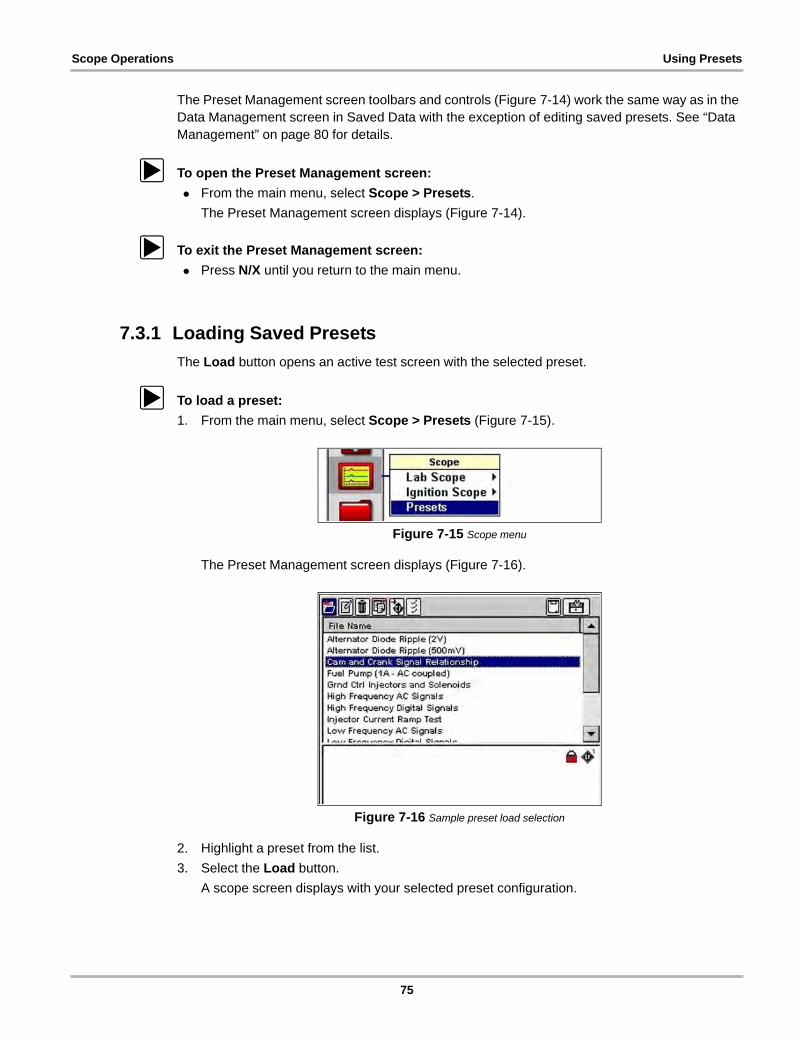
Scope Operations Using Presets
The Preset Management screen toolbars and controls (Figure 7-14) work the same way as in the Data Management screen in Saved Data with the exception of editing saved presets. See “Data Management” on page 80 for details.
z To open the Preset Management screen:
• From the main menu, select Scope > Presets.
The Preset Management screen displays (Figure 7-14).
z To exit the Preset Management screen:
• Press N/X until you return to the main menu.
7.3.1 Loading Saved Presets
The Load button opens an active test screen with the selected preset.
z To load a preset:
1. From the main menu, select Scope > Presets (Figure 7-15).
Figure 7-15 Scope menu
The Preset Management screen displays (Figure 7-16).
Figure 7-16 Sample preset load selection
2. Highlight a preset from the list.
3. Select the Load button.
A scope screen displays with your selected preset configuration.
75
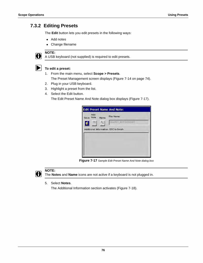
Scope Operations Using Presets
7.3.2 Editing Presets
The Edit button lets you edit presets in the following ways:
• Add notes
• Change filename
NOTE:i A USB keyboard (not supplied) is required to edit presets.
z To edit a preset:
1. From the main menu, select Scope > Presets.
The Preset Management screen displays (Figure 7-14 on page 74).
2. Plug in your USB keyboard.
3. Highlight a preset from the list.
4. Select the Edit button.
The Edit Preset Name And Note dialog box displays (Figure 7-17).
Figure 7-17 Sample Edit Preset Name And Note dialog box
NOTE:i The Notes and Name icons are not active if a keyboard is not plugged in.
5. Select Notes.
The Additional Information section activates (Figure 7-18).
76
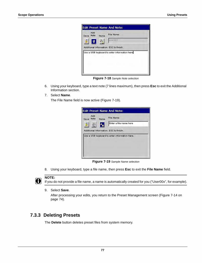
Scope Operations Using Presets
Figure 7-18 Sample Note selection
6. Using your keyboard, type a text note (7 lines maximum), then press Esc to exit the Additional Information section.
7. Select Name.
The File Name field is now active (Figure 7-19).
Figure 7-19 Sample Name selection
8. Using your keyboard, type a file name, then press Esc to exit the File Name field.
NOTE:i If you do not provide a file name, a name is automatically created for you (“User00x”, for example).
9. Select Save.
After processing your edits, you return to the Preset Management screen (Figure 7-14 on page 74).
7.3.3 Deleting Presets
The Delete button deletes preset files from system memory.
77
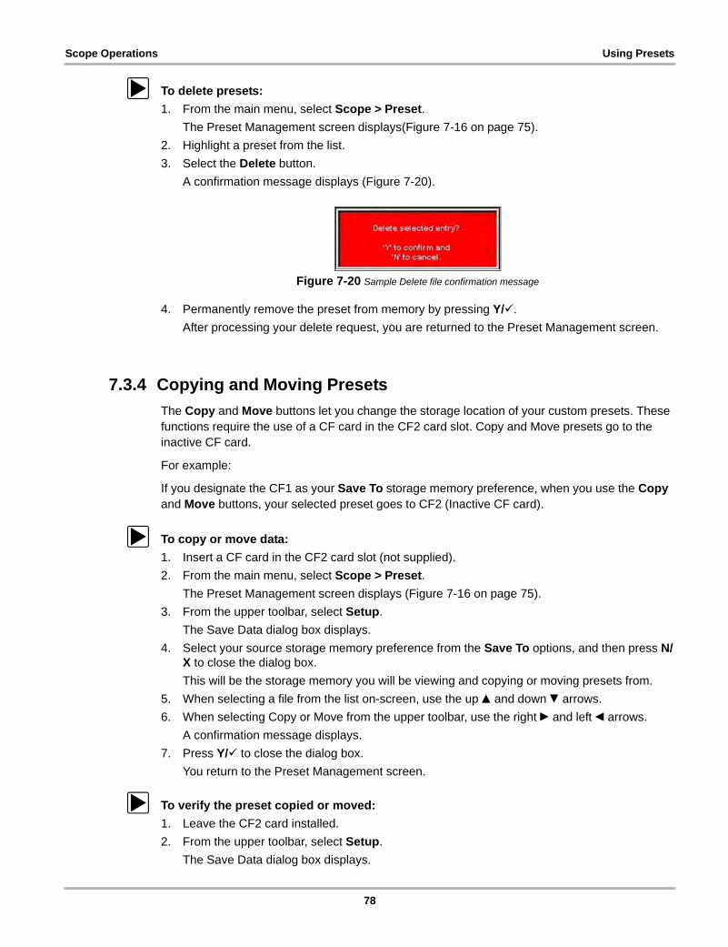
Scope Operations Using Presets
z To delete presets:
1. From the main menu, select Scope > Preset.
The Preset Management screen displays(Figure 7-16 on page 75).
2. Highlight a preset from the list.
3. Select the Delete button.
A confirmation message displays (Figure 7-20).
Figure 7-20 Sample Delete file confirmation message
4. Permanently remove the preset from memory by pressing Y/a.
After processing your delete request, you are returned to the Preset Management screen.
7.3.4 Copying and Moving Presets
The Copy and Move buttons let you change the storage location of your custom presets. These functions require the use of a CF card in the CF2 card slot. Copy and Move presets go to the inactive CF card.
For example:
If you designate the CF1 as your Save To storage memory preference, when you use the Copy and Move buttons, your selected preset goes to CF2 (Inactive CF card).
z To copy or move data:
1. Insert a CF card in the CF2 card slot (not supplied).
2. From the main menu, select Scope > Preset.
The Preset Management screen displays (Figure 7-16 on page 75).
3. From the upper toolbar, select Setup.
The Save Data dialog box displays.
4. Select your source storage memory preference from the Save To options, and then press N/X to close the dialog box.
This will be the storage memory you will be viewing and copying or moving presets from.
5. When selecting a file from the list on-screen, use the up b and down d arrows.
6. When selecting Copy or Move from the upper toolbar, use the right c and left e arrows.
A confirmation message displays.
7. Press Y/a to close the dialog box.
You return to the Preset Management screen.
z To verify the preset copied or moved:
1. Leave the CF2 card installed.
2. From the upper toolbar, select Setup.
The Save Data dialog box displays.
78
Scope Operations Using Presets
3. Select the destination storage memory preference from the Save To options, and then press N/X to close the dialog box.
When the Preset Management screen displays, you should see the preset(s) that you copied or moved from your source storage memory.
7.3.5 Selecting Multiple Presets
The Select All button highlights all the presets so you can delete, copy, or move all of the files simultaneously.
79
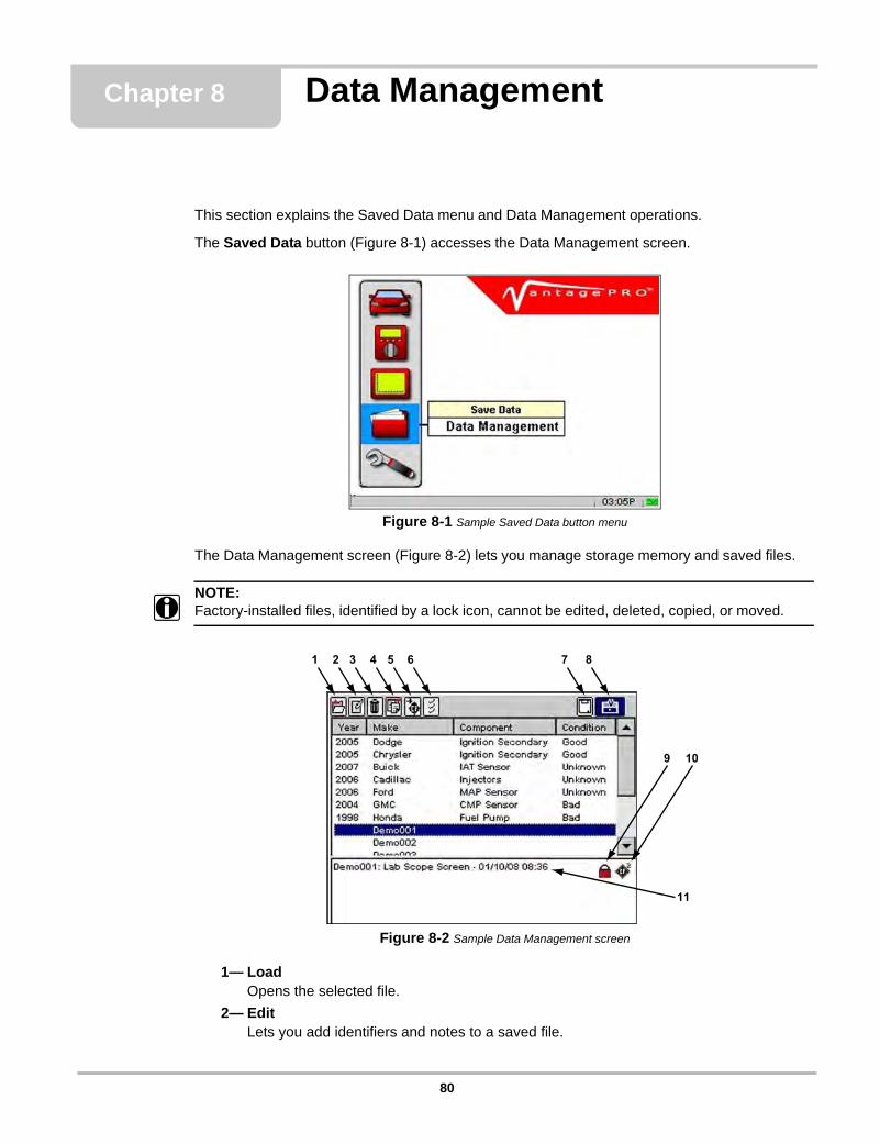
Chapter 8 Data Management
This section explains the Saved Data menu and Data Management operations.
The Saved Data button (Figure 8-1) accesses the Data Management screen.
Figure 8-1 Sample Saved Data button menu
The Data Management screen (Figure 8-2) lets you manage storage memory and saved files.
NOTE:i Factory-installed files, identified by a lock icon, cannot be edited, deleted, copied, or moved.
Figure 8-2 Sample Data Management screen
1— Load Opens the selected file.
2— Edit Lets you add identifiers and notes to a saved file.
80
Data Management Identifying Saved Files
3— Delete Erases the saved file(s) from storage memory.
4— Copy Lets you copy the selected file(s) from one CF slot to the other.
5— Move Lets you move the selected file(s) from one CF slot to the other.
6— Select All Selects all files.
7— InformationLets you see how many saved files you have and how much memory is available.
8— SetupProvides a shortcut to the Save Data utility dialog box that lets you set the location where files are saved. See “Save Data” on page 89 for details.
9— Lock Status IndicatorDisplays a lock icon when indicating that the file is factory-installed.
10—Storage Location IndicatorIndicates to which CF card the file is saved.
11—Additional InformationDisplays module source, type of data (screen, movie or snapshot), date, time, any custom notes, lock status and storage location information.
8.1 Identifying Saved FilesSaved files can display the following identification information:
• Year is the vehicle model year.
• Make is the vehicle manufacturer.
• Sensor is the component tested.
• Condition is for good, bad, or unknown status options.
For related information, refer to the following sections:
• “Saving Data” on page 43
• “Editing Saved Files” on page 82
8.2 Loading Saved FilesThe Load button lets you view saved test data and do the following:
• Modify the data view using the Zoom, Setup, Channel Number, Signal Zero Offset, and Cursors buttons.
• Review data using the Review button if the saved data contains more than one screen.
• Print the screen.
81
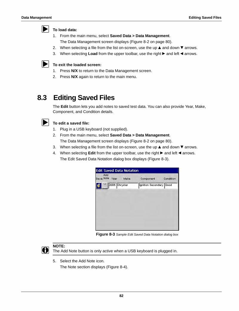
Data Management Editing Saved Files
z To load data:
1. From the main menu, select Saved Data > Data Management.
The Data Management screen displays (Figure 8-2 on page 80).
2. When selecting a file from the list on-screen, use the up b and down d arrows.
3. When selecting Load from the upper toolbar, use the right c and left e arrows.
z To exit the loaded screen:
1. Press N/X to return to the Data Management screen.
2. Press N/X again to return to the main menu.
8.3 Editing Saved FilesThe Edit button lets you add notes to saved test data. You can also provide Year, Make, Component, and Condition details.
z To edit a saved file:
1. Plug in a USB keyboard (not supplied).
2. From the main menu, select Saved Data > Data Management.
The Data Management screen displays (Figure 8-2 on page 80).
3. When selecting a file from the list on-screen, use the up b and down d arrows.
4. When selecting Edit from the upper toolbar, use the right c and left e arrows.
The Edit Saved Data Notation dialog box displays (Figure 8-3).
Figure 8-3 Sample Edit Saved Data Notation dialog box
NOTE:i The Add Note button is only active when a USB keyboard is plugged in.
5. Select the Add Note icon.
The Note section displays (Figure 8-4).
82
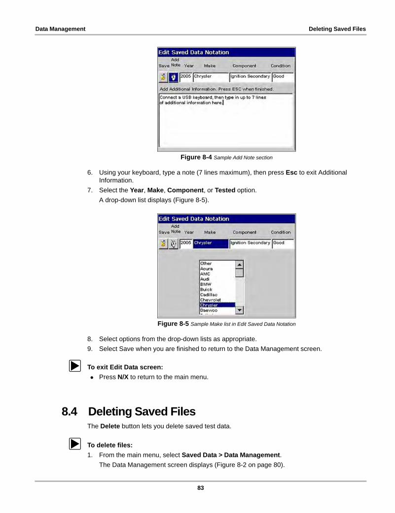
Data Management Deleting Saved Files
Figure 8-4 Sample Add Note section
6. Using your keyboard, type a note (7 lines maximum), then press Esc to exit Additional Information.
7. Select the Year, Make, Component, or Tested option.
A drop-down list displays (Figure 8-5).
Figure 8-5 Sample Make list in Edit Saved Data Notation
8. Select options from the drop-down lists as appropriate.
9. Select Save when you are finished to return to the Data Management screen.
z To exit Edit Data screen:
• Press N/X to return to the main menu.
8.4 Deleting Saved FilesThe Delete button lets you delete saved test data.
z To delete files:
1. From the main menu, select Saved Data > Data Management.
The Data Management screen displays (Figure 8-2 on page 80).
83
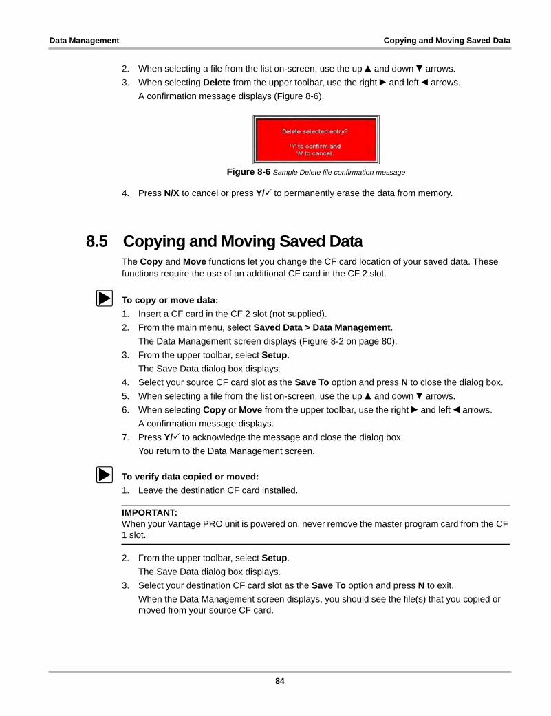
Data Management Copying and Moving Saved Data
2. When selecting a file from the list on-screen, use the up b and down d arrows.
3. When selecting Delete from the upper toolbar, use the right c and left e arrows.
A confirmation message displays (Figure 8-6).
Figure 8-6 Sample Delete file confirmation message
4. Press N/X to cancel or press Y/a to permanently erase the data from memory.
8.5 Copying and Moving Saved DataThe Copy and Move functions let you change the CF card location of your saved data. These functions require the use of an additional CF card in the CF 2 slot.
z To copy or move data:
1. Insert a CF card in the CF 2 slot (not supplied).
2. From the main menu, select Saved Data > Data Management.
The Data Management screen displays (Figure 8-2 on page 80).
3. From the upper toolbar, select Setup.
The Save Data dialog box displays.
4. Select your source CF card slot as the Save To option and press N to close the dialog box.
5. When selecting a file from the list on-screen, use the up b and down d arrows.
6. When selecting Copy or Move from the upper toolbar, use the right c and left e arrows.
A confirmation message displays.
7. Press Y/a to acknowledge the message and close the dialog box.
You return to the Data Management screen.
z To verify data copied or moved:
1. Leave the destination CF card installed.
IMPORTANT:When your Vantage PRO unit is powered on, never remove the master program card from the CF 1 slot.
2. From the upper toolbar, select Setup.
The Save Data dialog box displays.
3. Select your destination CF card slot as the Save To option and press N to exit.
When the Data Management screen displays, you should see the file(s) that you copied or moved from your source CF card.
84
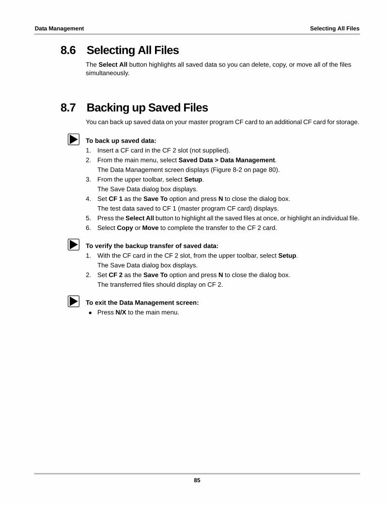
Data Management Selecting All Files
8.6 Selecting All FilesThe Select All button highlights all saved data so you can delete, copy, or move all of the files simultaneously.
8.7 Backing up Saved FilesYou can back up saved data on your master program CF card to an additional CF card for storage.
z To back up saved data:
1. Insert a CF card in the CF 2 slot (not supplied).
2. From the main menu, select Saved Data > Data Management.
The Data Management screen displays (Figure 8-2 on page 80).
3. From the upper toolbar, select Setup.
The Save Data dialog box displays.
4. Set CF 1 as the Save To option and press N to close the dialog box.
The test data saved to CF 1 (master program CF card) displays.
5. Press the Select All button to highlight all the saved files at once, or highlight an individual file.
6. Select Copy or Move to complete the transfer to the CF 2 card.
z To verify the backup transfer of saved data:
1. With the CF card in the CF 2 slot, from the upper toolbar, select Setup.
The Save Data dialog box displays.
2. Set CF 2 as the Save To option and press N to close the dialog box.
The transferred files should display on CF 2.
z To exit the Data Management screen:
• Press N/X to the main menu.
85
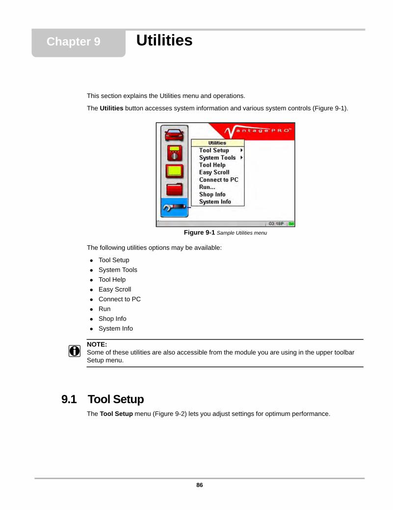
Chapter 9 Utilities
This section explains the Utilities menu and operations.
The Utilities button accesses system information and various system controls (Figure 9-1).
Figure 9-1 Sample Utilities menu
The following utilities options may be available:
• Tool Setup
• System Tools
• Tool Help
• Easy Scroll
• Connect to PC
• Run
• Shop Info
• System Info
NOTE:i Some of these utilities are also accessible from the module you are using in the upper toolbar
Setup menu.
9.1 Tool SetupThe Tool Setup menu (Figure 9-2) lets you adjust settings for optimum performance.
86
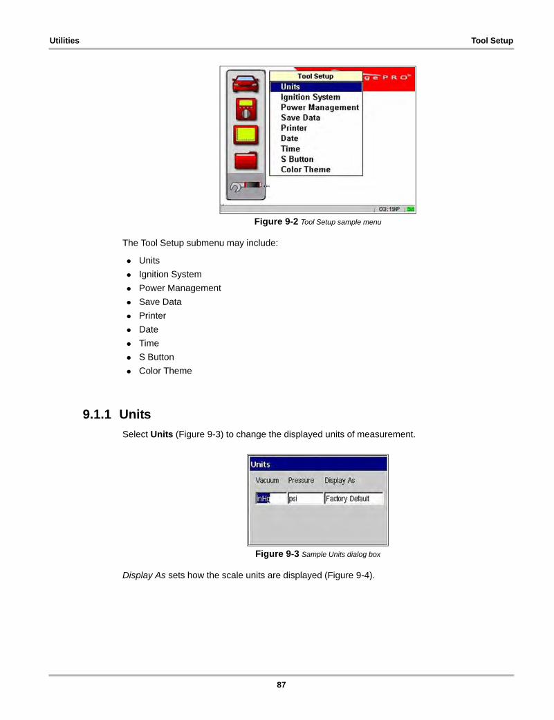
Utilities Tool Setup
Figure 9-2 Tool Setup sample menu
The Tool Setup submenu may include:
• Units
• Ignition System
• Power Management
• Save Data
• Printer
• Date
• Time
• S Button
• Color Theme
9.1.1 Units
Select Units (Figure 9-3) to change the displayed units of measurement.
Figure 9-3 Sample Units dialog box
Display As sets how the scale units are displayed (Figure 9-4).
87
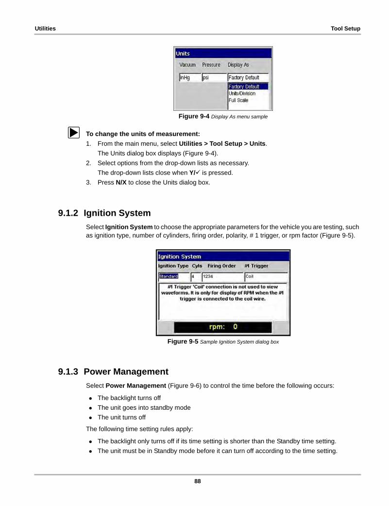
Utilities Tool Setup
Figure 9-4 Display As menu sample
z To change the units of measurement:
1. From the main menu, select Utilities > Tool Setup > Units.
The Units dialog box displays (Figure 9-4).
2. Select options from the drop-down lists as necessary.
The drop-down lists close when Y/a is pressed.
3. Press N/X to close the Units dialog box.
9.1.2 Ignition System
Select Ignition System to choose the appropriate parameters for the vehicle you are testing, such as ignition type, number of cylinders, firing order, polarity, # 1 trigger, or rpm factor (Figure 9-5).
Figure 9-5 Sample Ignition System dialog box
9.1.3 Power Management
Select Power Management (Figure 9-6) to control the time before the following occurs:
• The backlight turns off
• The unit goes into standby mode
• The unit turns off
The following time setting rules apply:
• The backlight only turns off if its time setting is shorter than the Standby time setting.
• The unit must be in Standby mode before it can turn off according to the time setting.
88
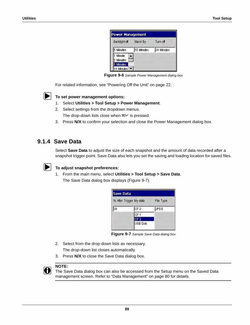
Utilities Tool Setup
Figure 9-6 Sample Power Management dialog box
For related information, see “Powering Off the Unit” on page 22.
z To set power management options:
1. Select Utilities > Tool Setup > Power Management.
2. Select settings from the dropdown menus.
The drop-down lists close when Y/a is pressed.
3. Press N/X to confirm your selection and close the Power Management dialog box.
9.1.4 Save Data
Select Save Data to adjust the size of each snapshot and the amount of data recorded after a snapshot trigger-point. Save Data also lets you set the saving and loading location for saved files.
z To adjust snapshot preferences:
1. From the main menu, select Utilities > Tool Setup > Save Data.
The Save Data dialog box displays (Figure 9-7).
Figure 9-7 Sample Save Data dialog box
2. Select from the drop-down lists as necessary.
The drop-down list closes automatically.
3. Press N/X to close the Save Data dialog box.
NOTE:i The Save Data dialog box can also be accessed from the Setup menu on the Saved Data
management screen. Refer to “Data Management” on page 80 for details.
89
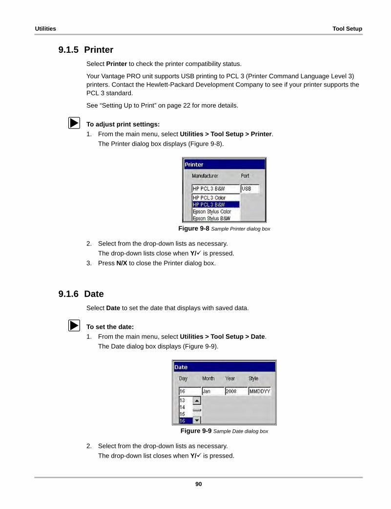
Utilities Tool Setup
9.1.5 Printer
Select Printer to check the printer compatibility status.
Your Vantage PRO unit supports USB printing to PCL 3 (Printer Command Language Level 3) printers. Contact the Hewlett-Packard Development Company to see if your printer supports the PCL 3 standard.
See “Setting Up to Print” on page 22 for more details.
z To adjust print settings:
1. From the main menu, select Utilities > Tool Setup > Printer.
The Printer dialog box displays (Figure 9-8).
Figure 9-8 Sample Printer dialog box
2. Select from the drop-down lists as necessary.
The drop-down lists close when Y/a is pressed.
3. Press N/X to close the Printer dialog box.
9.1.6 Date
Select Date to set the date that displays with saved data.
z To set the date:
1. From the main menu, select Utilities > Tool Setup > Date.
The Date dialog box displays (Figure 9-9).
Figure 9-9 Sample Date dialog box
2. Select from the drop-down lists as necessary.
The drop-down list closes when Y/a is pressed.
90
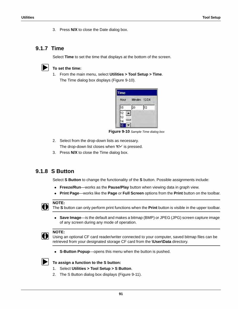
Utilities Tool Setup
3. Press N/X to close the Date dialog box.
9.1.7 Time
Select Time to set the time that displays at the bottom of the screen.
z To set the time:
1. From the main menu, select Utilities > Tool Setup > Time.
The Time dialog box displays (Figure 9-10).
Figure 9-10 Sample Time dialog box
2. Select from the drop-down lists as necessary.
The drop-down list closes when Y/a is pressed.
3. Press N/X to close the Time dialog box.
9.1.8 S Button
Select S Button to change the functionality of the S button. Possible assignments include:
• Freeze/Run—works as the Pause/Play button when viewing data in graph view.
• Print Page—works like the Page or Full Screen options from the Print button on the toolbar.
NOTE:i The S button can only perform print functions when the Print button is visible in the upper toolbar.
• Save Image—is the default and makes a bitmap (BMP) or JPEG (JPG) screen capture image of any screen during any mode of operation.
NOTE:i Using an optional CF card reader/writer connected to your computer, saved bitmap files can be
retrieved from your designated storage CF card from the \User\Data directory.
• S-Button Popup—opens this menu when the button is pushed.
z To assign a function to the S button:
1. Select Utilities > Tool Setup > S Button.
2. The S Button dialog box displays (Figure 9-11).
91
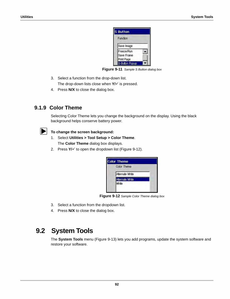
Utilities System Tools
Figure 9-11 Sample S Button dialog box
3. Select a function from the drop-down list.
The drop-down lists close when Y/a is pressed.
4. Press N/X to close the dialog box.
9.1.9 Color Theme
Selecting Color Theme lets you change the background on the display. Using the black background helps conserve battery power.
z To change the screen background:
1. Select Utilities > Tool Setup > Color Theme.
The Color Theme dialog box displays.
2. Press Y/a to open the dropdown list (Figure 9-12).
Figure 9-12 Sample Color Theme dialog box
3. Select a function from the dropdown list.
4. Press N/X to close the dialog box.
9.2 System ToolsThe System Tools menu (Figure 9-13) lets you add programs, update the system software and restore your software.
92
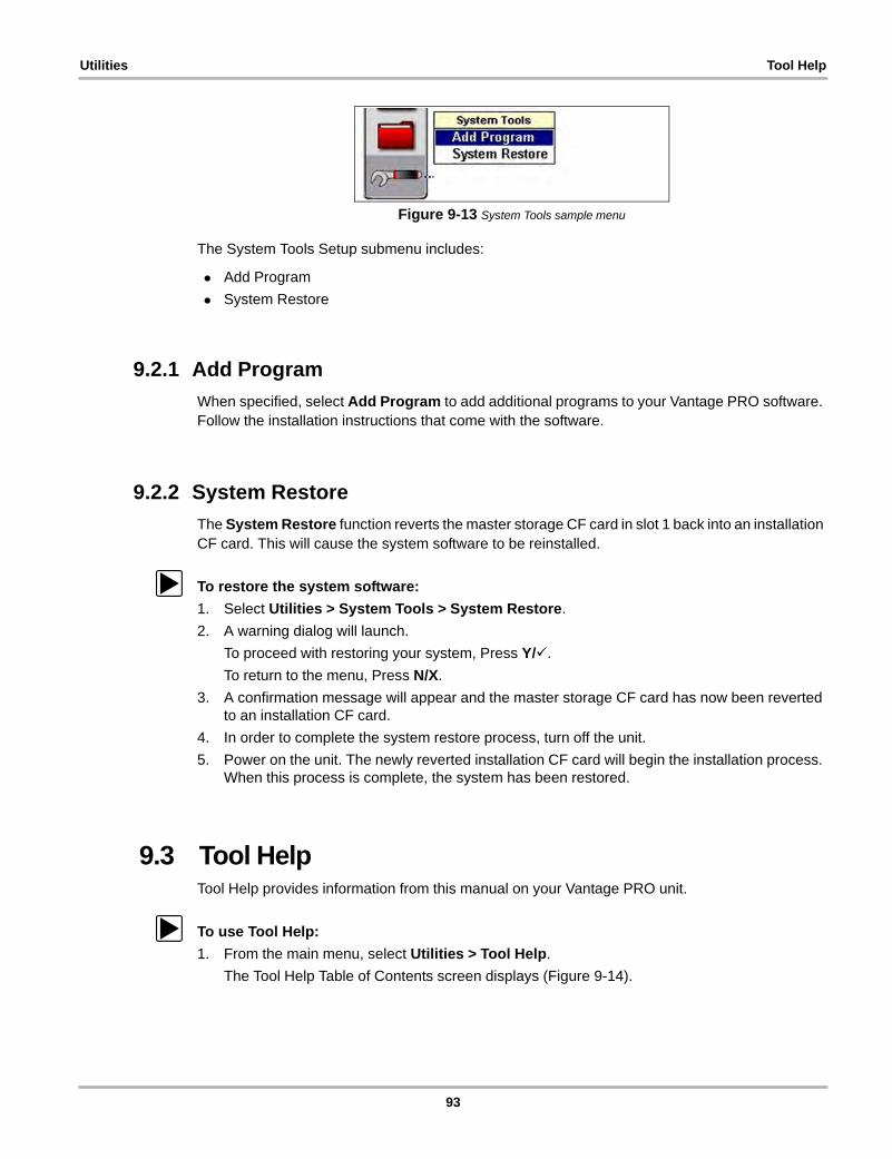
Utilities Tool Help
Figure 9-13 System Tools sample menu
The System Tools Setup submenu includes:
• Add Program
• System Restore
9.2.1 Add Program
When specified, select Add Program to add additional programs to your Vantage PRO software. Follow the installation instructions that come with the software.
9.2.2 System Restore
The System Restore function reverts the master storage CF card in slot 1 back into an installation CF card. This will cause the system software to be reinstalled.
z To restore the system software:
1. Select Utilities > System Tools > System Restore.
2. A warning dialog will launch.
To proceed with restoring your system, Press Y/a.
To return to the menu, Press N/X.
3. A confirmation message will appear and the master storage CF card has now been reverted to an installation CF card.
4. In order to complete the system restore process, turn off the unit.
5. Power on the unit. The newly reverted installation CF card will begin the installation process. When this process is complete, the system has been restored.
9.3 Tool HelpTool Help provides information from this manual on your Vantage PRO unit.
z To use Tool Help:
1. From the main menu, select Utilities > Tool Help.
The Tool Help Table of Contents screen displays (Figure 9-14).
93
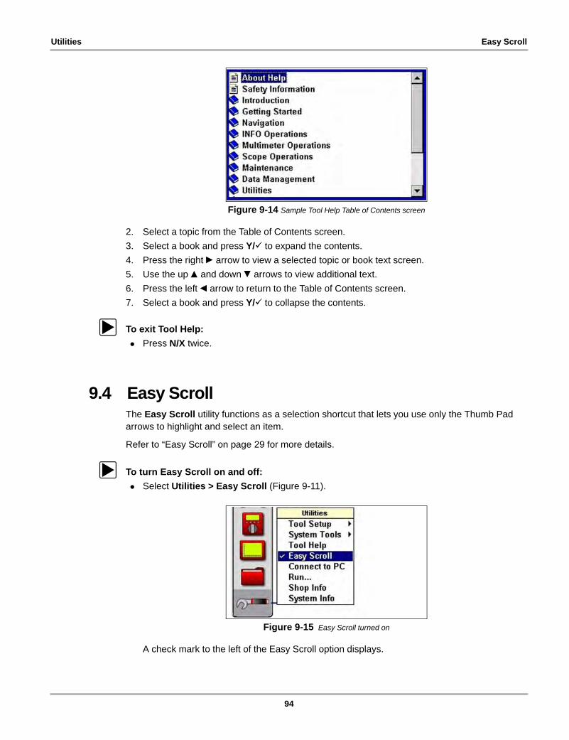
Utilities Easy Scroll
Figure 9-14 Sample Tool Help Table of Contents screen
2. Select a topic from the Table of Contents screen.
3. Select a book and press Y/a to expand the contents.
4. Press the right c arrow to view a selected topic or book text screen.
5. Use the up b and down d arrows to view additional text.
6. Press the left e arrow to return to the Table of Contents screen.
7. Select a book and press Y/a to collapse the contents.
z To exit Tool Help:
• Press N/X twice.
9.4 Easy ScrollThe Easy Scroll utility functions as a selection shortcut that lets you use only the Thumb Pad arrows to highlight and select an item.
Refer to “Easy Scroll” on page 29 for more details.
z To turn Easy Scroll on and off:
• Select Utilities > Easy Scroll (Figure 9-11).
Figure 9-15 Easy Scroll turned on
A check mark to the left of the Easy Scroll option displays.
94
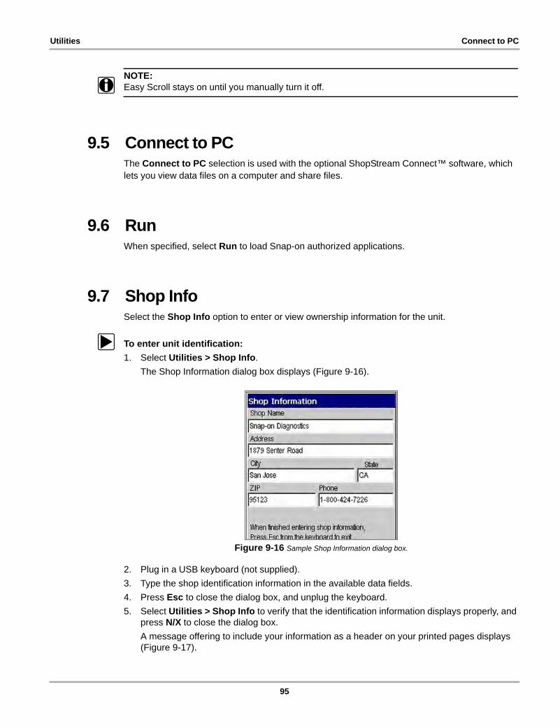
Utilities Connect to PC
NOTE:i Easy Scroll stays on until you manually turn it off.
9.5 Connect to PCThe Connect to PC selection is used with the optional ShopStream Connect™ software, which lets you view data files on a computer and share files.
9.6 RunWhen specified, select Run to load Snap-on authorized applications.
9.7 Shop InfoSelect the Shop Info option to enter or view ownership information for the unit.
z To enter unit identification:
1. Select Utilities > Shop Info.
The Shop Information dialog box displays (Figure 9-16).
Figure 9-16 Sample Shop Information dialog box.
2. Plug in a USB keyboard (not supplied).
3. Type the shop identification information in the available data fields.
4. Press Esc to close the dialog box, and unplug the keyboard.
5. Select Utilities > Shop Info to verify that the identification information displays properly, and press N/X to close the dialog box.
A message offering to include your information as a header on your printed pages displays (Figure 9-17).
95
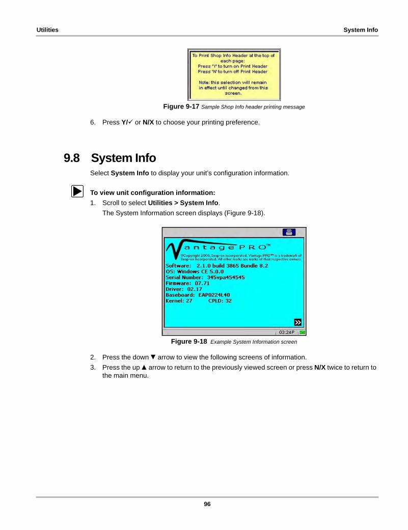
Utilities System Info
Figure 9-17 Sample Shop Info header printing message
6. Press Y/a or N/X to choose your printing preference.
9.8 System InfoSelect System Info to display your unit’s configuration information.
z To view unit configuration information:
1. Scroll to select Utilities > System Info.
The System Information screen displays (Figure 9-18).
Figure 9-18 Example System Information screen
2. Press the down d arrow to view the following screens of information.
3. Press the up b arrow to return to the previously viewed screen or press N/X twice to return to the main menu.
96

Chapter 10 Maintenance
This section explains the following maintenance issues:
• Cleaning and damage inspection
• Battery pack
• CompactFlash® cards
• Storage tips
• Disposal requirements (environmental hazards)
10.1 Cleaning and Damage InspectionWhen using the Vantage PRO unit, make sure to do the following:
• Before and after each use, check the housing, wiring, and connectors for dirt and damage.
• At the end of each working day, clean the housing, wiring, and connectors with a soft cloth and gentle all-purpose cleaner.
IMPORTANT:Avoid using abrasive or corrosive cleaning products, especially when cleaning the screen.
10.2 Battery PackTo prolong the life of your battery pack when your Vantage PRO unit is not in use, power off your Vantage PRO unit and remove the battery pack.
10.2.1 Replacing the Battery Pack
When your battery pack no longer holds a charge, call your Snap-on dealer to order a new one. Refer to “Using the Battery Pack” on page 17 for more details.
After replacing the old battery, call Rechargeable Battery Recycling Corporation (RBRC) at 1(800) 822-8837 (USA), or refer to their web site at http://www.rbrc.org for the nearest recycling location and instructions for proper battery disposal.
10.3 10-Amp Fuse The Vantage PRO unit uses one 10-amp mini fuse to protect the amp circuit. The fuse is located in the back of the unit (Figure 10-1).
97
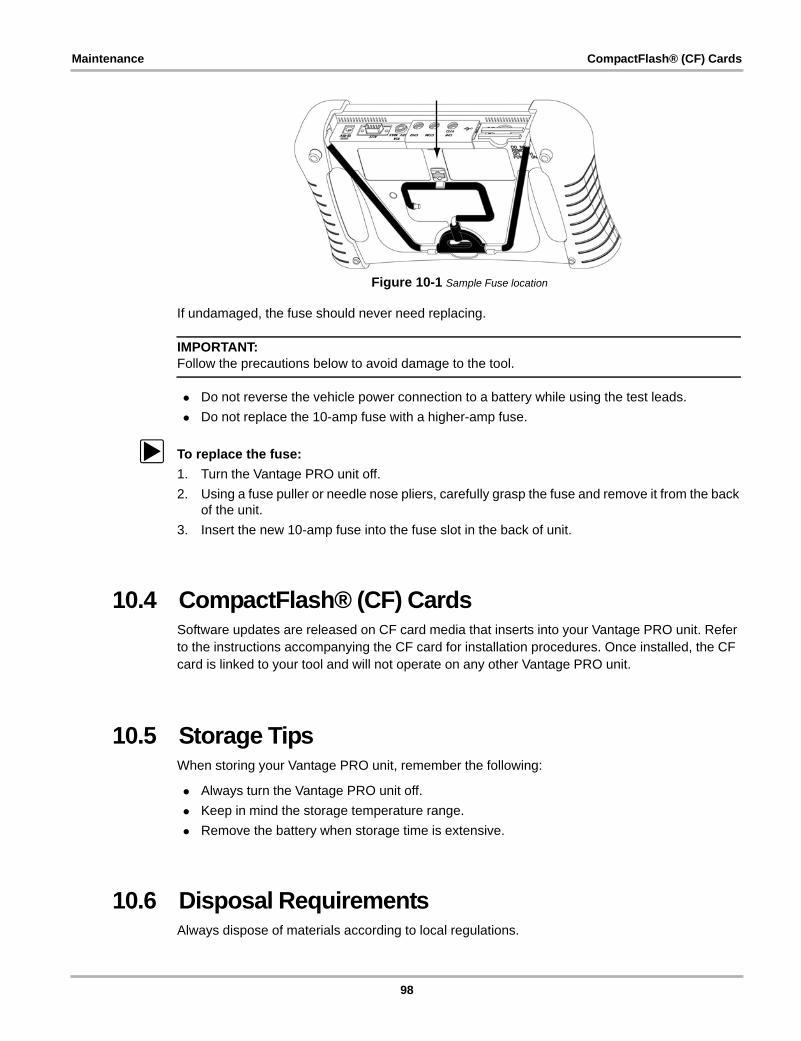
Maintenance CompactFlash® (CF) Cards
Figure 10-1 Sample Fuse location
If undamaged, the fuse should never need replacing.
IMPORTANT:Follow the precautions below to avoid damage to the tool.
• Do not reverse the vehicle power connection to a battery while using the test leads.
• Do not replace the 10-amp fuse with a higher-amp fuse.
z To replace the fuse:
1. Turn the Vantage PRO unit off.
2. Using a fuse puller or needle nose pliers, carefully grasp the fuse and remove it from the back of the unit.
3. Insert the new 10-amp fuse into the fuse slot in the back of unit.
10.4 CompactFlash® (CF) CardsSoftware updates are released on CF card media that inserts into your Vantage PRO unit. Refer to the instructions accompanying the CF card for installation procedures. Once installed, the CF card is linked to your tool and will not operate on any other Vantage PRO unit.
10.5 Storage TipsWhen storing your Vantage PRO unit, remember the following:
• Always turn the Vantage PRO unit off.
• Keep in mind the storage temperature range.
• Remove the battery when storage time is extensive.
10.6 Disposal RequirementsAlways dispose of materials according to local regulations.
98
Appendix A Troubleshooting
The following are solutions for problems that can occur while using your Vantage PRO unit.
A.1 Battery Pack Not ChargingIf the battery pack does not charge:
• The battery pack may not be installed in the battery charger unit properly.
Make sure the battery charger unit is receiving power; and, without using force, adjust the battery pack installation in the battery charger unit until the red status light displays.
• The battery pack may be too hot.
Allow the battery pack to cool to at least 104°F (40°C). If left in the battery charger unit, once the proper room temperature is achieved, charging will begin.
• The battery pack may be too cold.
Allow the battery pack to warm to at least 32°F (0°C). If left in the battery charger unit, once the proper room temperature is achieved, charging will begin.
• The battery pack may be dead.
The battery pack must be replaced. See “Replacing the Battery Pack” on page 97. Use another power source to continue working. See “Supplying Power” on page 17.
A.2 Unit Will Not Power OnThe following conditions will prevent your Vantage PRO unit from powering on:
• No master storage CF card in CF Slot 1.
• No or discharged battery pack and no auxiliary power connected. See “Supplying Power” on page 17.
A.3 Emergency RestartIf your Vantage PRO unit Pauses or will not power off, you can perform an emergency restart.
z To perform an emergency restart:
1. Remove the left handgrip.
2. Locate the emergency restart button in the lower right corner on the back of the unit (Figure A-1).
99
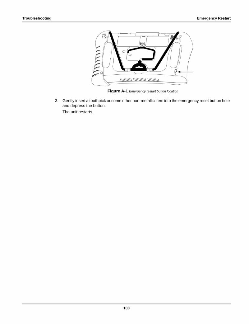
Troubleshooting Emergency Restart
Figure A-1 Emergency restart button location
3. Gently insert a toothpick or some other non-metallic item into the emergency reset button hole and depress the button.
The unit restarts.
100
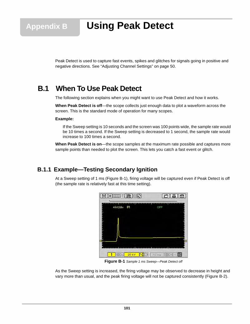
Appendix B Using Peak Detect
Peak Detect is used to capture fast events, spikes and glitches for signals going in positive and negative directions. See “Adjusting Channel Settings” on page 50.
B.1 When To Use Peak DetectThe following section explains when you might want to use Peak Detect and how it works.
When Peak Detect is off—the scope collects just enough data to plot a waveform across the screen. This is the standard mode of operation for many scopes.
Example:
If the Sweep setting is 10 seconds and the screen was 100 points wide, the sample rate would be 10 times a second. If the Sweep setting is decreased to 1 second, the sample rate would increase to 100 times a second.
When Peak Detect is on—the scope samples at the maximum rate possible and captures more sample points than needed to plot the screen. This lets you catch a fast event or glitch.
B.1.1 Example—Testing Secondary Ignition
At a Sweep setting of 1 ms (Figure B-1), firing voltage will be captured even if Peak Detect is off (the sample rate is relatively fast at this time setting).
Figure B-1 Sample 1 ms Sweep—Peak Detect off
As the Sweep setting is increased, the firing voltage may be observed to decrease in height and vary more than usual, and the peak firing voltage will not be captured consistently (Figure B-2).
101
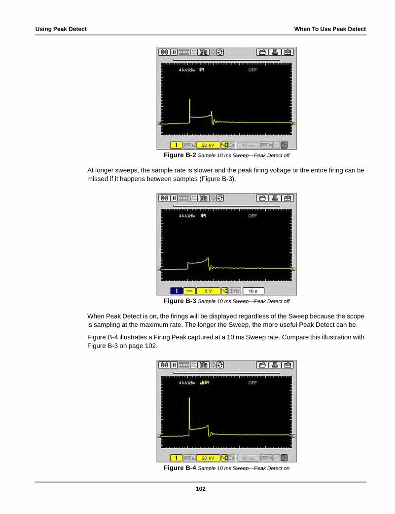
Using Peak Detect When To Use Peak Detect
Figure B-2 Sample 10 ms Sweep—Peak Detect off
At longer sweeps, the sample rate is slower and the peak firing voltage or the entire firing can be missed if it happens between samples (Figure B-3).
Figure B-3 Sample 10 ms Sweep—Peak Detect off
When Peak Detect is on, the firings will be displayed regardless of the Sweep because the scope is sampling at the maximum rate. The longer the Sweep, the more useful Peak Detect can be.
Figure B-4 illustrates a Firing Peak captured at a 10 ms Sweep rate. Compare this illustration with Figure B-3 on page 102.
Figure B-4 Sample 10 ms Sweep—Peak Detect on
102
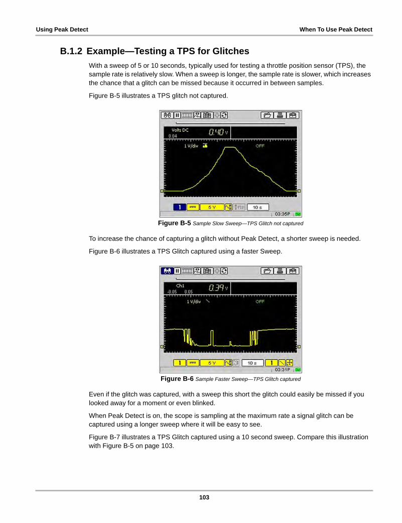
Using Peak Detect When To Use Peak Detect
B.1.2 Example—Testing a TPS for Glitches
With a sweep of 5 or 10 seconds, typically used for testing a throttle position sensor (TPS), the sample rate is relatively slow. When a sweep is longer, the sample rate is slower, which increases the chance that a glitch can be missed because it occurred in between samples.
Figure B-5 illustrates a TPS glitch not captured.
Figure B-5 Sample Slow Sweep—TPS Glitch not captured
To increase the chance of capturing a glitch without Peak Detect, a shorter sweep is needed.
Figure B-6 illustrates a TPS Glitch captured using a faster Sweep.
Figure B-6 Sample Faster Sweep—TPS Glitch captured
Even if the glitch was captured, with a sweep this short the glitch could easily be missed if you looked away for a moment or even blinked.
When Peak Detect is on, the scope is sampling at the maximum rate a signal glitch can be captured using a longer sweep where it will be easy to see.
Figure B-7 illustrates a TPS Glitch captured using a 10 second sweep. Compare this illustration with Figure B-5 on page 103.
103
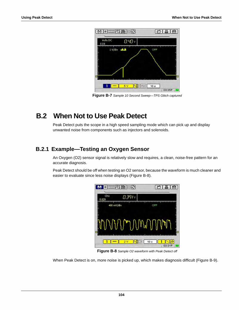
Using Peak Detect When Not to Use Peak Detect
Figure B-7 Sample 10 Second Sweep—TPS Glitch captured
B.2 When Not to Use Peak DetectPeak Detect puts the scope in a high speed sampling mode which can pick up and display unwanted noise from components such as injectors and solenoids.
B.2.1 Example—Testing an Oxygen Sensor
An Oxygen (O2) sensor signal is relatively slow and requires, a clean, noise-free pattern for an accurate diagnosis.
Peak Detect should be off when testing an O2 sensor, because the waveform is much cleaner and easier to evaluate since less noise displays (Figure B-8).
Figure B-8 Sample O2 waveform with Peak Detect off
When Peak Detect is on, more noise is picked up, which makes diagnosis difficult (Figure B-9).
104
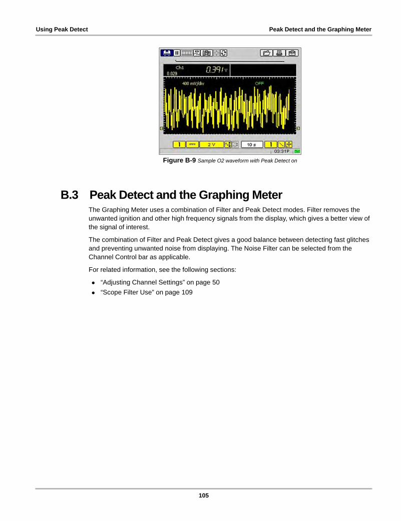
Using Peak Detect Peak Detect and the Graphing Meter
Figure B-9 Sample O2 waveform with Peak Detect on
B.3 Peak Detect and the Graphing MeterThe Graphing Meter uses a combination of Filter and Peak Detect modes. Filter removes the unwanted ignition and other high frequency signals from the display, which gives a better view of the signal of interest.
The combination of Filter and Peak Detect gives a good balance between detecting fast glitches and preventing unwanted noise from displaying. The Noise Filter can be selected from the Channel Control bar as applicable.
For related information, see the following sections:
• “Adjusting Channel Settings” on page 50
• “Scope Filter Use” on page 109
105

Appendix C Using Noise Filter
If glitches are being detected and no vehicle problems are observed, noise may be the cause. As a precaution, do the following:
• Use shielded leads
• Route the leads away from secondary ignition components.
• Verify the test connections.
• If noise is still suspected to be a problem, turn on the Filter. See “Channel Number” on page 51 for procedures.
NOTE:i The Filter may also eliminate extremely fast glitches.
C.1 When to Use FilterThe following sections explain when to use the filter with the Graphing Meter and the Scope.
C.1.1 Graphing Meter Filter Use
In the Graphing Meter, the filter minimizes noise by ignoring or smoothing out fast spikes.
Calculated Measurements
When conducting a calculated measurement test (Frequency Pulse Width, MC Dwell or Duty Cycle) the filter is used to ignore very fast spikes (20 uS and faster) from sources like the ignition system.
Figure C-1 illustrates noise from the ignition system when conducting the Graphing Meter Frequency test with Peak Detect on and Filter off.
106
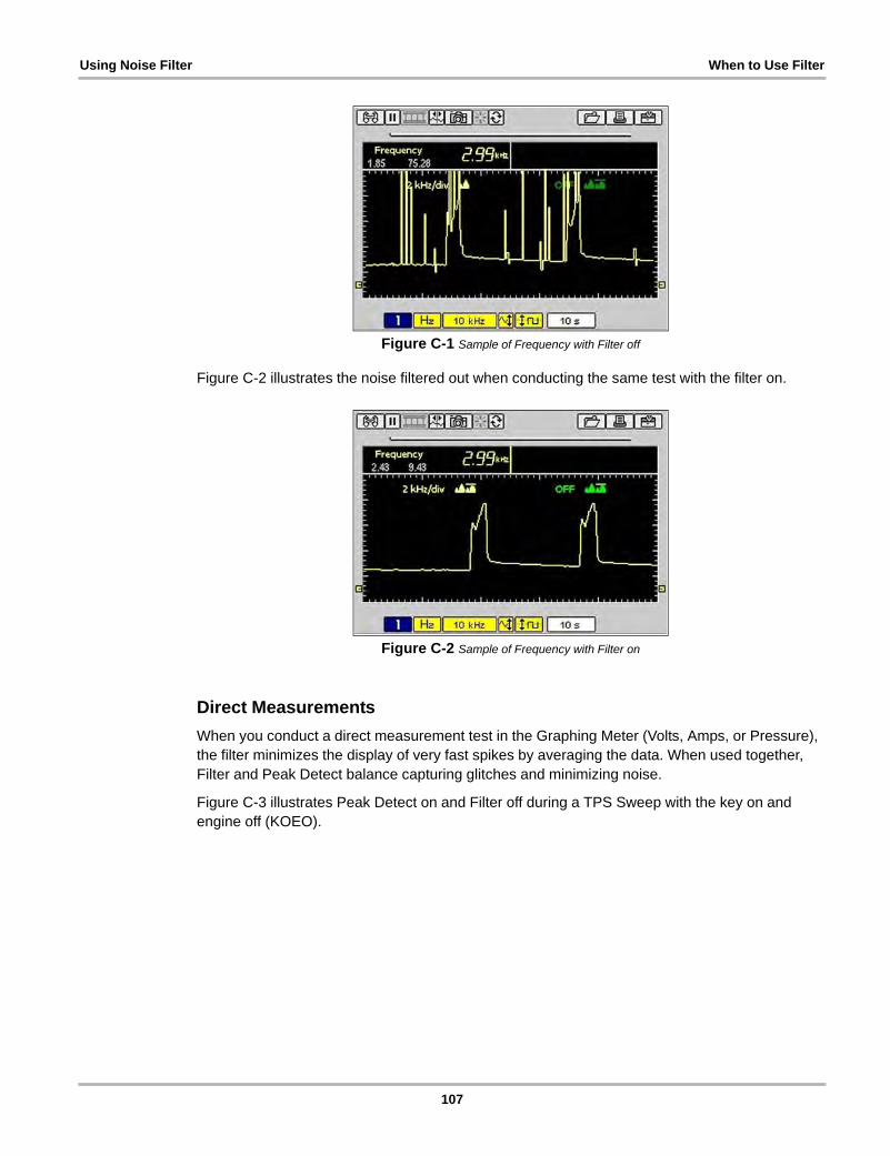
Using Noise Filter When to Use Filter
Figure C-1 Sample of Frequency with Filter off
Figure C-2 illustrates the noise filtered out when conducting the same test with the filter on.
Figure C-2 Sample of Frequency with Filter on
Direct Measurements
When you conduct a direct measurement test in the Graphing Meter (Volts, Amps, or Pressure), the filter minimizes the display of very fast spikes by averaging the data. When used together, Filter and Peak Detect balance capturing glitches and minimizing noise.
Figure C-3 illustrates Peak Detect on and Filter off during a TPS Sweep with the key on and engine off (KOEO).
107
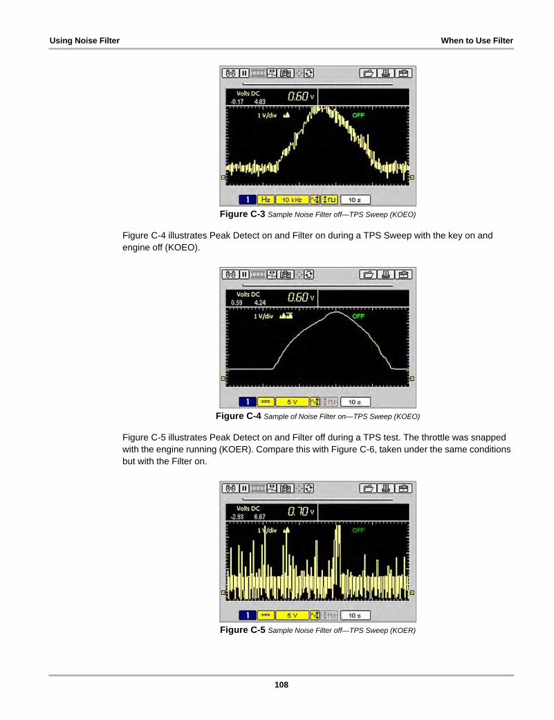
Using Noise Filter When to Use Filter
Figure C-3 Sample Noise Filter off—TPS Sweep (KOEO)
Figure C-4 illustrates Peak Detect on and Filter on during a TPS Sweep with the key on and engine off (KOEO).
Figure C-4 Sample of Noise Filter on—TPS Sweep (KOEO)
Figure C-5 illustrates Peak Detect on and Filter off during a TPS test. The throttle was snapped with the engine running (KOER). Compare this with Figure C-6, taken under the same conditions but with the Filter on.
Figure C-5 Sample Noise Filter off—TPS Sweep (KOER)
108
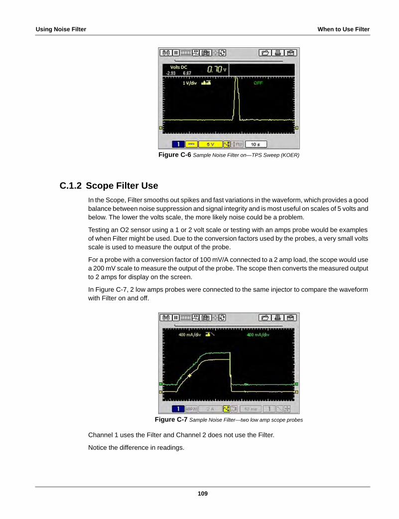
Using Noise Filter When to Use Filter
Figure C-6 Sample Noise Filter on—TPS Sweep (KOER)
C.1.2 Scope Filter Use
In the Scope, Filter smooths out spikes and fast variations in the waveform, which provides a good balance between noise suppression and signal integrity and is most useful on scales of 5 volts and below. The lower the volts scale, the more likely noise could be a problem.
Testing an O2 sensor using a 1 or 2 volt scale or testing with an amps probe would be examples of when Filter might be used. Due to the conversion factors used by the probes, a very small volts scale is used to measure the output of the probe.
For a probe with a conversion factor of 100 mV/A connected to a 2 amp load, the scope would use a 200 mV scale to measure the output of the probe. The scope then converts the measured output to 2 amps for display on the screen.
In Figure C-7, 2 low amps probes were connected to the same injector to compare the waveform with Filter on and off.
Figure C-7 Sample Noise Filter—two low amp scope probes
Channel 1 uses the Filter and Channel 2 does not use the Filter.
Notice the difference in readings.
109
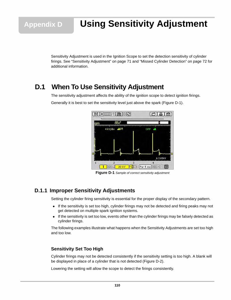
Appendix D Using Sensitivity Adjustment
Sensitivity Adjustment is used in the Ignition Scope to set the detection sensitivity of cylinder firings. See “Sensitivity Adjustment” on page 71 and “Missed Cylinder Detection” on page 72 for additional information.
D.1 When To Use Sensitivity AdjustmentThe sensitivity adjustment affects the ability of the ignition scope to detect ignition firings.
Generally it is best to set the sensitivity level just above the spark (Figure D-1).
Figure D-1 Sample of correct sensitivity adjustment
D.1.1 Improper Sensitivity Adjustments
Setting the cylinder firing sensitivity is essential for the proper display of the secondary pattern.
• If the sensitivity is set too high, cylinder firings may not be detected and firing peaks may not get detected on multiple spark ignition systems.
• If the sensitivity is set too low, events other than the cylinder firings may be falsely detected as cylinder firings.
The following examples illustrate what happens when the Sensitivity Adjustments are set too high and too low.
Sensitivity Set Too High
Cylinder firings may not be detected consistently if the sensitivity setting is too high. A blank will be displayed in place of a cylinder that is not detected (Figure D-2).
Lowering the setting will allow the scope to detect the firings consistently.
110
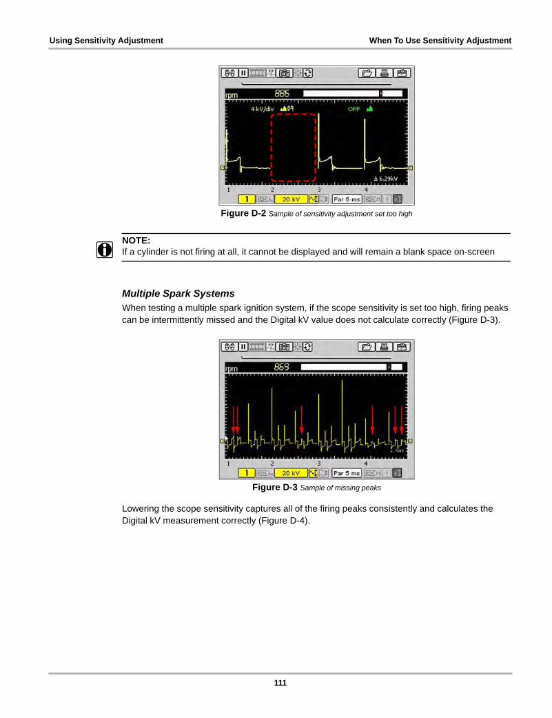
Using Sensitivity Adjustment When To Use Sensitivity Adjustment
Figure D-2 Sample of sensitivity adjustment set too high
NOTE:i If a cylinder is not firing at all, it cannot be displayed and will remain a blank space on-screen
Multiple Spark SystemsWhen testing a multiple spark ignition system, if the scope sensitivity is set too high, firing peaks can be intermittently missed and the Digital kV value does not calculate correctly (Figure D-3).
Figure D-3 Sample of missing peaks
Lowering the scope sensitivity captures all of the firing peaks consistently and calculates the Digital kV measurement correctly (Figure D-4).
111
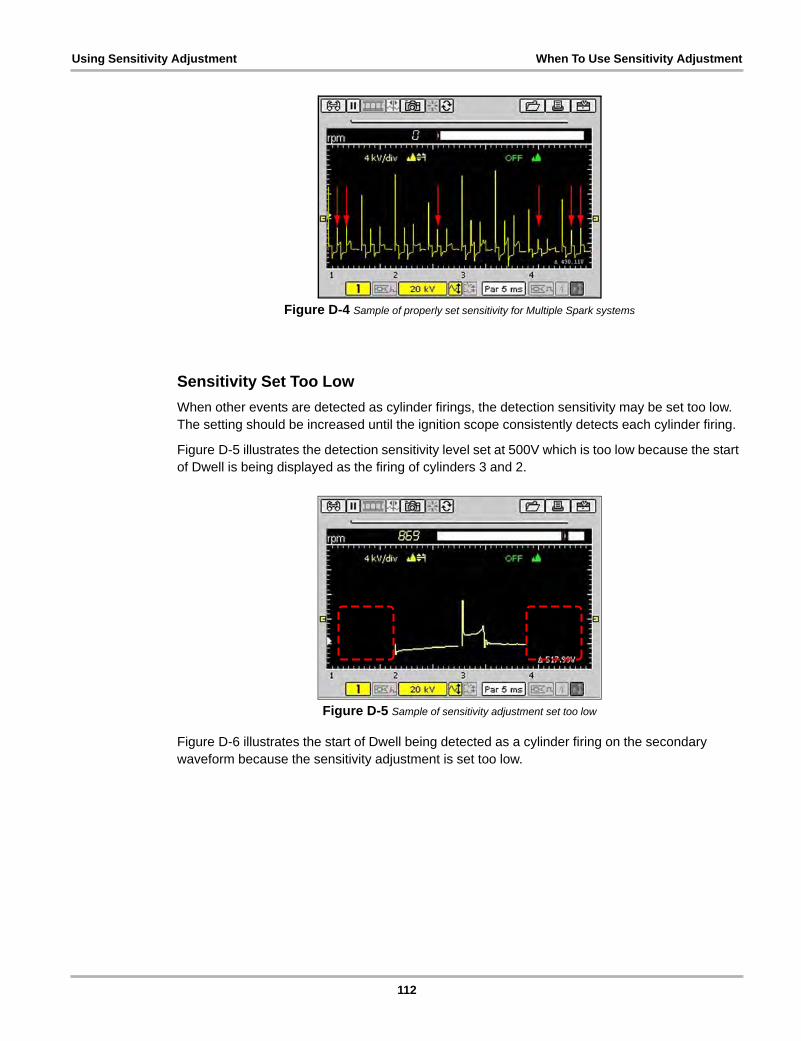
Using Sensitivity Adjustment When To Use Sensitivity Adjustment
Figure D-4 Sample of properly set sensitivity for Multiple Spark systems
Sensitivity Set Too Low
When other events are detected as cylinder firings, the detection sensitivity may be set too low. The setting should be increased until the ignition scope consistently detects each cylinder firing.
Figure D-5 illustrates the detection sensitivity level set at 500V which is too low because the start of Dwell is being displayed as the firing of cylinders 3 and 2.
Figure D-5 Sample of sensitivity adjustment set too low
Figure D-6 illustrates the start of Dwell being detected as a cylinder firing on the secondary waveform because the sensitivity adjustment is set too low.
112
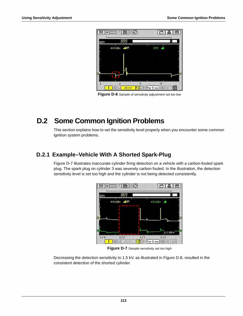
Using Sensitivity Adjustment Some Common Ignition Problems
Figure D-6 Sample of sensitivity adjustment set too low
D.2 Some Common Ignition ProblemsThis section explains how to set the sensitivity level properly when you encounter some common ignition system problems.
D.2.1 Example–Vehicle With A Shorted Spark-Plug
Figure D-7 illustrates inaccurate cylinder firing detection on a vehicle with a carbon-fouled spark plug. The spark plug on cylinder 3 was severely carbon fouled. In the illustration, the detection sensitivity level is set too high and the cylinder is not being detected consistently.
Figure D-7 Sample sensitivity set too high
Decreasing the detection sensitivity to 1.5 kV, as illustrated in Figure D-8, resulted in the consistent detection of the shorted cylinder.
113
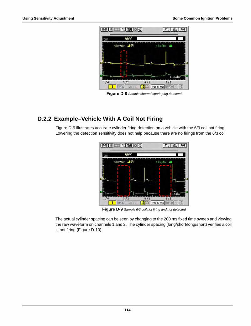
Using Sensitivity Adjustment Some Common Ignition Problems
Figure D-8 Sample shorted spark-plug detected
D.2.2 Example–Vehicle With A Coil Not Firing
Figure D-9 illustrates accurate cylinder firing detection on a vehicle with the 6/3 coil not firing. Lowering the detection sensitivity does not help because there are no firings from the 6/3 coil.
Figure D-9 Sample 6/3 coil not firing and not detected
The actual cylinder spacing can be seen by changing to the 200 ms fixed time sweep and viewing the raw waveform on channels 1 and 2. The cylinder spacing (long/short/long/short) verifies a coil is not firing (Figure D-10).
114
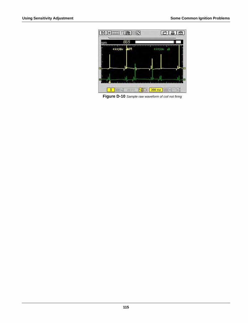
Using Sensitivity Adjustment Some Common Ignition Problems
Figure D-10 Sample raw waveform of coil not firing
115

Index
Numerics10-Minute Electronic Class, 6015-Minute Ignition Class, 60
AAC power adapter
technical specifications, 7AC voltage, 10AC/DC power adapter, 13adding notes. See editing dataadjustment, 71alligator clips, 16amps, 7, 8
connecting, 5
Bback up saved files, 85backlight, 88batteries, 7battery pack
about, 14charger, 14charging, 17disposing of, 97extending the life of, 18installing, 18low battery warning, 19not charging, 99power status, 27replacing, 97time to charge, 18using, 17–18working when battery is low, 19
brightness/contrast, 5, 20
Ccables, 15–16
channel 1, 15channel 2, 16connecting, 21
capabilitiesscope, 8test instrument, 8
channel control bar, 50channel number, 51color theme setting, 92CompactFlash® cards
slot technical specs, 7
component testoperations, 31–59
component tests, 31–59connecting to a vehicle, 35features and benefits, 59how to, 60identify test vehicle, 32new vehicle ID, 32performing tests, 35–57power user tests, 60previous vehicles, 33selecting a test, 34view component information, 57–59
control buttons, 11–12brightness/contrast, 12N button, 11power, 12S button, 12Thumb Pad, 12Y button, 11
cursors, 39
DDB9F connector, 5DC power jack, 5DC voltage, 10deleting data, 77, 83diode, 5, 8display, 7display as, 45, 87display trigger, 55–57disposal requirements, 98duty cycle, 9DVOM
and digital meter, 63
Eeasy scroll, 29, 94edit, 80editing data, 82emergency restart, 99
FFeatures and Benefits, 59filter, 105, 106–109fuse, 7
replacing, 97
116

Index
Ggrid, 47
Hhelp. See tool helpHow To, 60
Iidentifying saved files, 81identifying the test vehicle, 32ignition patterns, 69
cylinder, 70parade, 70raster, 70superimposed, 70
ignition scope, 69–73ignition patterns, 69
ignition system, 46Illustrated Terms and Definitions, 60inverse colors, 49
Jjump bar, 29
Llab scope, 67load, 80loading data, 75, 81
Mmaintenance, 97–98
10-amp fuse, 97battery pack, 97cleaning and damage inspection, 97CompactFlash® (CF) cards, 98disposal requirements, 98storage tips, 98
making selections, 27manual conventions
notes, 1, 2master program CF card, 7MC dwell, 9multimeter
digital meter, 63graphing meter, 62operations, 61–65performing tests, 65selecting software, 62
Nnew vehicle ID, 32noise filter, 51, 105, 106–109No-Start Basics, 60
not powering on, 99
OO2 Sensor & Feedback System Analysis, 60operating specifications, 7–11operating temperature, 7
Ppausing data, 37PC, connect to, 95peak detect, 51, 101–105performing tests, 35power button, 5power sources, 13–15Power User Tests. See testspresets
copying and moving, 78deleting, 77editing, 76exiting, 75loading, 75management screen, 75selecting all, 79using, 74–79
previous vehicles ID, 33printer setup, 17printing
connecting a printer, 90printing a screen, 44probe, 52, 71
Rresetting min/max data, 44
SS button, 5safety
information, ivsaving data, 43scale, 52scales display, 49scope, 73–79
capabilities, 8ignition scope, 69lab scope, 67operations, 66–77performing tests, 73presets, 74selecting software, 67single cylinder ignition, 70
selecting component tests, 34
117

Index
setup options, 44grid, 47ignition system, 46inverse colors, 49scales display, 49trigger display, 48units, 45
setup. See tool setupShopStream Connect, 22signal zero offset, 53single cylinder ignition, 70snapshot, 37, 38, 40–42stand, the, 6Standby mode, 22
setting, 88storage temperature, 7storage tips, 98sweep, 54system info, 96
Ttechnical specifications, 7test instrument capabilities, 8–11test leads
connecting, 21tests
Power User, 60tips, 60
tests leadsjacks, 12
threshold, 53Auto Threshold Select (ATS), 53Manual Threshold Select (MTS), 53
thumb pad, 4tool help, 93tool setup, 86, 92transflective screen, 4trigger display, 48trigger. See display trigger
Uunits, 45USB keyboard, 76USB ports, 5, 13Utilities menu
Connect to PC, 95
Vvehicle power adapters, 14view options, 36viewing component information, 57
Zzoom, 38
118