Embed Size (px)
Citation preview
Please keep these instructions safe.Should you move house, please hand
them over to the next occupier.
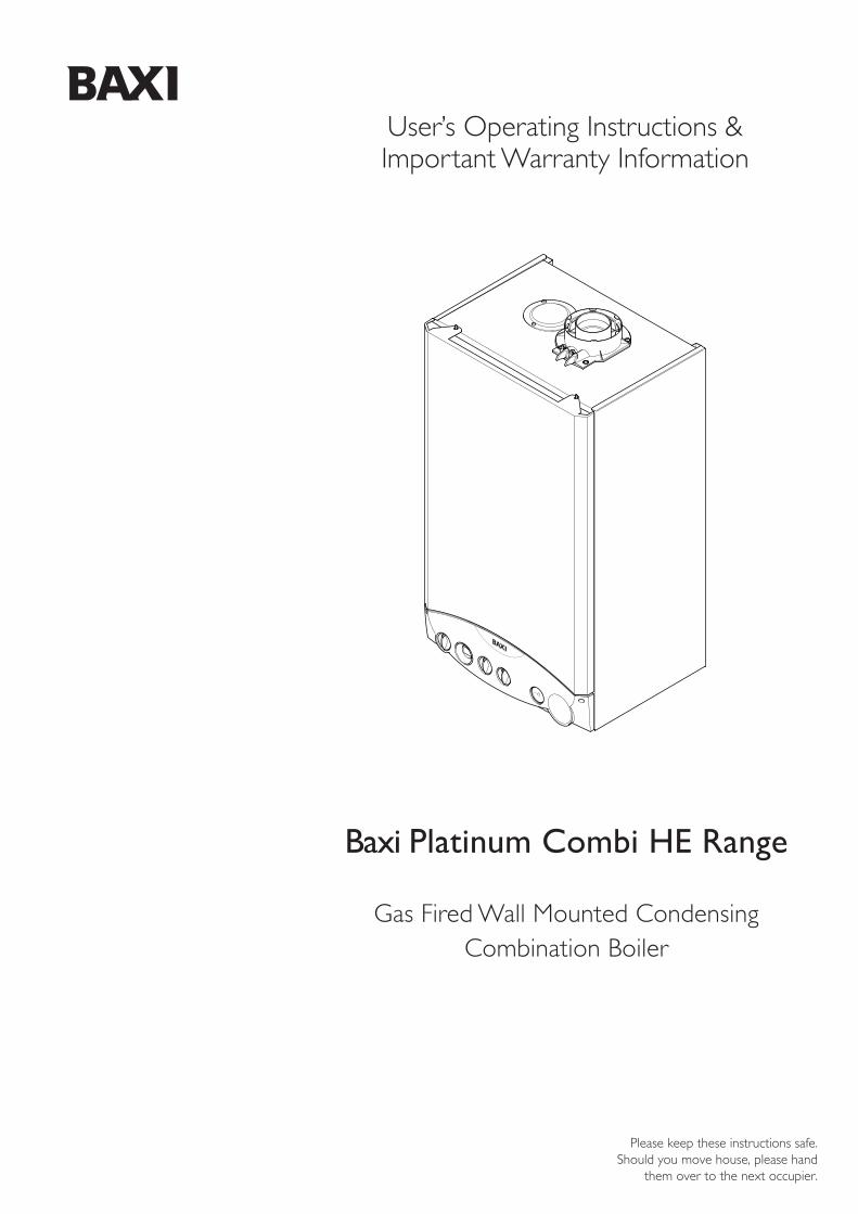
Baxi Platinum Combi HE Range
Gas Fired Wall Mounted CondensingCombination Boiler
User’s Operating Instructions &Important Warranty Information
2
Natural Gas
Baxi Platinum Combi 24 HEG.C.No 47 075 20Baxi Platinum Combi 28 HEG.C.No 47 075 21Baxi Platinum Combi 33 HEG.C.No 47 075 22
Warranty
heateam the service division of Baxi Heating UK Limited providea 5 year free warranty for your peace of mind. Once your boileris registered with us and in the unlikely event your boiler developsa fault and your installer is unable to assist, heateam will provide afree service to you provided the boiler is under 5 years old.Otherwise heateam will offer a competitive fixed price repair rateincluding parts, labour and VAT. To arrange an engineer visiteither in warranty or out, please call heateam on 08700 60 30 60.It would help if you had your boiler serial number when you call,the serial number is shown on the back cover of this guide.
Annual Service
To ensure you receive the maximum efficiency from your boilerwe recommend your boiler has an annual service so you andyour family can continue to enjoy heating and hot water comfort.To arrange an annual service from one of our Baxi Heating UKLimited heating experts, please call heateam on 08700 60 30 60to arrange a visit convenient to you.
Benchmark Commissioning Check List
Please ensure that your installer hands you the boiler Installation& Service Instructions with the “Benchmark” CommissioningChecklist sections completed. The details in the Checklist will berequired in the event of any warranty work. Keep the instructionsin a safe place and ensure that the Service Interval Record at theback is completed at each service visit.
5 Years Free Warranty - register today
To receive your 5 years free warranty please complete the formsupplied with the boiler or simply call heateam, the servicedivision of Baxi Heating UK Limited on 08700 60 30 60.
Baxi is one of the leading manufacturers of domestic
heating products in the UK.
Our first priority is to give a high quality service to our
customers. Quality is designed into every Baxi product -
products which fulfil the demands and needs of customers,
offering choice, efficiency and reliability.
To keep ahead of changing trends, we have made a
commitment to develop new ideas using the
latest technology - with the aim of continuing to
make the products that customers want to buy.
Everyone who works at Baxi has a commitment to quality
because we know that satisfied customers mean continued
success.
We hope you get a satisfactory service from Baxi. If not,
please let us know.
Baxi is a BS-EN ISO 9001 Accredited Company
1.0 Operating the Boiler
3
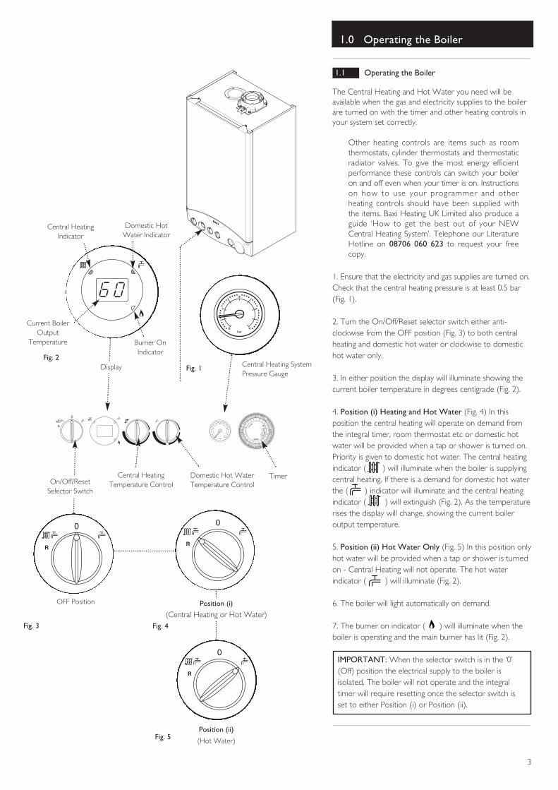
1.1 Operating the Boiler
The Central Heating and Hot Water you need will beavailable when the gas and electricity supplies to the boilerare turned on with the timer and other heating controls inyour system set correctly.
Other heating controls are items such as roomthermostats, cylinder thermostats and thermostaticradiator valves. To give the most energy efficientperformance these controls can switch your boileron and off even when your timer is on. Instructionson how to use your programmer and otherheating controls should have been supplied withthe items. Baxi Heating UK Limited also produce aguide ‘How to get the best out of your NEWCentral Heating System’. Telephone our LiteratureHotline on 08706 060 623 to request your freecopy.
1. Ensure that the electricity and gas supplies are turned on.Check that the central heating pressure is at least 0.5 bar(Fig. 1).
2. Turn the On/Off/Reset selector switch either anti-clockwise from the OFF position (Fig. 3) to both centralheating and domestic hot water or clockwise to domestichot water only.
3. In either position the display will illuminate showing thecurrent boiler temperature in degrees centigrade (Fig. 2).
4. Position (i) Heating and Hot Water (Fig. 4) In thisposition the central heating will operate on demand fromthe integral timer, room thermostat etc or domestic hotwater will be provided when a tap or shower is turned on.Priority is given to domestic hot water. The central heatingindicator ( ) will illuminate when the boiler is supplyingcentral heating. If there is a demand for domestic hot waterthe ( ) indicator will illuminate and the central heatingindicator ( ) will extinguish (Fig. 2). As the temperaturerises the display will change, showing the current boileroutput temperature.
5. Position (ii) Hot Water Only (Fig. 5) In this position onlyhot water will be provided when a tap or shower is turnedon - Central Heating will not operate. The hot waterindicator ( ) will illuminate (Fig. 2).
6. The boiler will light automatically on demand.
7. The burner on indicator ( ) will illuminate when theboiler is operating and the main burner has lit (Fig. 2).
IMPORTANT: When the selector switch is in the ‘0’(Off) position the electrical supply to the boiler isisolated. The boiler will not operate and the integraltimer will require resetting once the selector switch isset to either Position (i) or Position (ii).
2
1
0 4
3
bar
R
123
4
5P
M7
89
10
1112 1 2
3
4
5A
M7
89
10
1112
GRASSLIN
0
Position (ii)
(Hot Water)
Fig. 4
Fig. 5
OFF Position
Fig. 3
Fig. 1
2
1
0 4
3
bar
Central Heating SystemPressure Gauge
Position (i)
(Central Heating or Hot Water)
On/Off/ResetSelector Switch
Fig. 2
Central HeatingTemperature Control
Domestic Hot WaterTemperature Control
Central HeatingIndicator
Domestic HotWater Indicator
Burner OnIndicator
Current BoilerOutput
Temperature
Display
Timer
1.0 Operating the Boiler
4
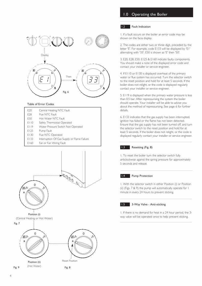
1.2 Fault Indication
1. If a fault occurs on the boiler an error code may beshown on the facia display.
2. The codes are either two or three digit, preceded by theletter 'E'. For example, code E133 will be displayed by 'E1'alternating with '33'. E50 is shown as 'E' then '50'.
3. E20, E28, E50, E125 & E160 indicate faulty components.You should make a note of the displayed error code andcontact your installer or service engineer.
4. If E110 or E130 is displayed overheat of the primarywater or flue system has occurred. Turn the selector switchto the reset position and hold for at least 5 seconds. If theboiler does not relight, or the code is displayed regularlycontact your installer or service engineer.
5. E119 is displayed when the primary water pressure is lessthan 0.5 bar. After repressurising the system the boilershould operate. Your installer will be able to advise youabout the method of repressurising. See page 6 for furtherdetails.
6. E133 indicates that the gas supply has been interrupted,ignition has failed or the flame has not been detected.Ensure that the gas supply has not been turned off, and turnthe selector switch to the reset position and hold for atleast 5 seconds. If the boiler does not relight, or the code isdisplayed regularly contact your installer or service engineer.
1.3 Resetting (Fig. 8)
1. To reset the boiler turn the selector switch fullyanticlockwise against the spring pressure for approximately5 seconds and release.
1.4 Pump Protection
1. With the selector switch in either Position (i) or Position(ii) (Figs. 7 & 9) the pump will automatically operate for 1minute in every 24 hours to prevent sticking.
1.5 3-Way Valve - Anti-sticking
1. If there is no demand for heat in a 24 hour period, the 3-way valve will be operated once to help prevent sticking.
Central Heating NTC FaultFlue NTC FaultHot Water NTC Fault Safety Thermostat OperatedWater Pressure Switch Not OperatedPump FaultFlue NTC OperatedInterruption Of Gas Supply or Flame FailureFan or Fan Wiring Fault
E20E28E50E110E119E125E130E133E160
Table of Error Codes
2
1
0 4
3
bar
R
123
4
5P
M7
89
10
1112 1 2
3
4
5A
M7
89
10
1112
GRASSLIN
0
Display
Then
Fig. 6
Fig. 7
Fig. 9
Reset Position
Fig. 8
Position (ii)
(Hot Water)
Position (i)
(Central Heating or Hot Water)
1.0 Operating the Boiler
5
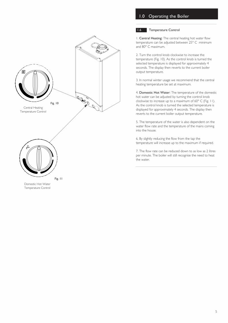
1.6 Temperature Control
1. Central Heating: The central heating hot water flowtemperature can be adjusted between 25° C minimumand 80° C maximum.
2. Turn the control knob clockwise to increase thetemperature (Fig. 10). As the control knob is turned theselected temperature is displayed for approximately 4seconds. The display then reverts to the current boileroutput temperature.
3. In normal winter usage we recommend that the centralheating temperature be set at maximum.
4. Domestic Hot Water: The temperature of the domestichot water can be adjusted by turning the control knobclockwise to increase up to a maximum of 60° C (Fig. 11).As the control knob is turned the selected temperature isdisplayed for approximately 4 seconds. The display thenreverts to the current boiler output temperature.
5. The temperature of the water is also dependent on thewater flow rate and the temperature of the mains cominginto the house.
6. By slightly reducing the flow from the tap thetemperature will increase up to the maximum if required.
7. The flow rate can be reduced down to as low as 2 litresper minute. The boiler will still recognise the need to heatthe water.
Domestic Hot WaterTemperature Control
Fig. 10Central Heating
Temperature Control
Fig. 11
1.0 Operating the Boiler
6
2
1
0 4
3
bar
2
1
0 4
3
bar
2
1
0 43
bar
2
1
0 4
3
bar
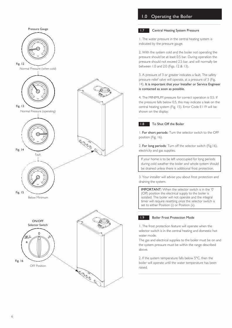
ON/OFFSelector Switch
OFF Position
Fig. 16
Normal Pressure (when cold)
Normal Pressure (operating)
Fig. 12
Fault
Fig. 13
Below Minimum
Fig. 14
Fig. 15
Pressure Gauge 1.7 Central Heating System Pressure
1. The water pressure in the central heating system isindicated by the pressure gauge.
2. With the system cold and the boiler not operating thepressure should be at least 0.5 bar. During operation thepressure should not exceed 2.5 bar, and will normally bebetween 1.0 and 2.0 (Figs. 12 & 13).
3. A pressure of 3 or greater indicates a fault. The safetypressure relief valve will operate, at a pressure of 3 (Fig.14). It is important that your Installer or Service Engineeris contacted as soon as possible.
4. The MINIMUM pressure for correct operation is 0.5. Ifthe pressure falls below 0.5, this may indicate a leak on thecentral heating system (Fig. 15). Error Code E119 will beshown on the display.
1.8 To Shut Off the Boiler
1. For short periods: Turn the selector switch to the OFFposition (Fig. 16).
2. For long periods: Turn off the selector switch (Fig.16),electricity and gas supplies.
If your home is to be left unoccupied for long periodsduring cold weather the boiler and whole system shouldbe drained unless there is additional frost protection.
3. Your installer will advise you about frost protection anddraining the system.
IMPORTANT: When the selector switch is in the ‘0’(Off) position the electrical supply to the boiler isisolated. The boiler will not operate and the integraltimer will require resetting once the selector switch isset to either Position (i) or Position (ii).
1.9 Boiler Frost Protection Mode
1. The frost protection feature will operate when theselector switch is in the central heating and domestic hotwater mode.The gas and electrical supplies to the boiler must be on andthe system pressure must be within the range describedabove.
2. If the system temperature falls below 5°C, then theboiler will operate until the water temperature has beenraised.
2.0 Care of the Boiler
7
2.1 Servicing and Repair of your Boiler
heateam can service and repair your boiler if your installeris not able to.
Our Baxi Heating UK Limited trained heating experts willquickly get your heating and hot water working again. Ifyour boiler is out of its free 3 year period, heateam canprovide a competitive fixed price repair rate including parts,labour and VAT.
To find out more call heateam on 08700 60 30 60, openMonday to Friday 8am - 6pm, weekends and bank holidays8.30am - 2pm, closed on Christmas and New Years Day.An appointment convenient for you can be arranged. Itwould help if you had your boiler serial number when youcall, the serial number is shown on the back cover of thisguide.
2.2 Cleaning the Outer case
The painted panels should be wiped with a damp cloth andthen dried completely.
3.0 Timer
8
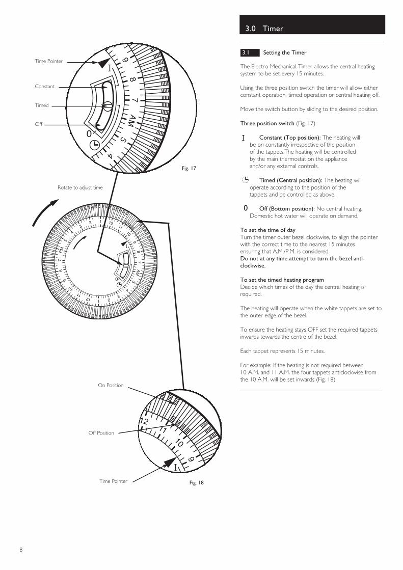
3.1 Setting the Timer
The Electro-Mechanical Timer allows the central heatingsystem to be set every 15 minutes.
Using the three position switch the timer will allow eitherconstant operation, timed operation or central heating off.
Move the switch button by sliding to the desired position.
Three position switch (Fig. 17)
Constant (Top position): The heating will be on constantly irrespective of the position of the tappets.The heating will be controlled by the main thermostat on the appliance and/or any external controls.
Timed (Central position): The heating will operate according to the position of the tappets and be controlled as above.
0 Off (Bottom position): No central heating. Domestic hot water will operate on demand.
To set the time of dayTurn the timer outer bezel clockwise, to align the pointerwith the correct time to the nearest 15 minutesensuring that A.M./P.M. is considered.Do not at any time attempt to turn the bezel anti-clockwise.
To set the timed heating programDecide which times of the day the central heating isrequired.
The heating will operate when the white tappets are set tothe outer edge of the bezel.
To ensure the heating stays OFF set the required tappetsinwards towards the centre of the bezel.
Each tappet represents 15 minutes.
For example: If the heating is not required between 10 A.M. and 11 A.M. the four tappets anticlockwise fromthe 10 A.M. will be set inwards (Fig. 18).
23
4
5A
M7
89
10
N
0
9
10
1112
123
4
5P
M7
89
10
1112 1 2
3
4
5A
M7
89
10
1112
GRASSLIN
0
4
Constant
Time Pointer
Timed
Off
Rotate to adjust time
Off Position
On Position
Time Pointer
Fig. 17
Fig. 18
4.0 Clearances
9
Fig. 19
Fig. 20
2
1
0 4
3
bar
R
123
4
5P
M7
89
10
1112 1 2
3
4
5A
M7
89
10
1112
GRASSLIN
0
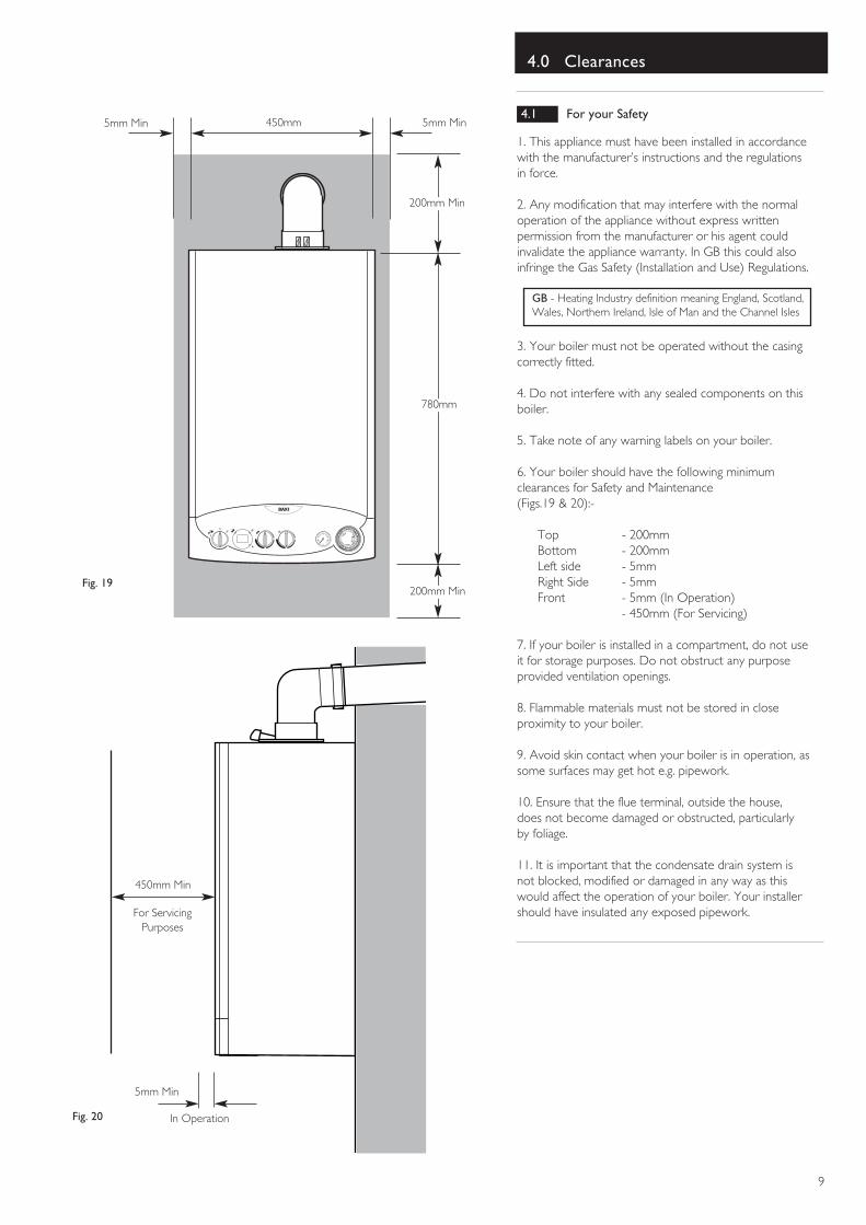
200mm Min
780mm
450mm
200mm Min
5mm Min
5mm Min
450mm Min
For ServicingPurposes
In Operation
5mm Min4.1 For your Safety
1. This appliance must have been installed in accordancewith the manufacturer’s instructions and the regulationsin force.
2. Any modification that may interfere with the normaloperation of the appliance without express writtenpermission from the manufacturer or his agent couldinvalidate the appliance warranty. In GB this could alsoinfringe the Gas Safety (Installation and Use) Regulations.
3. Your boiler must not be operated without the casingcorrectly fitted.
4. Do not interfere with any sealed components on thisboiler.
5. Take note of any warning labels on your boiler.
6. Your boiler should have the following minimumclearances for Safety and Maintenance (Figs.19 & 20):-
Top - 200mmBottom - 200mmLeft side - 5mmRight Side - 5mmFront - 5mm (In Operation)
- 450mm (For Servicing)
7. If your boiler is installed in a compartment, do not useit for storage purposes. Do not obstruct any purposeprovided ventilation openings.
8. Flammable materials must not be stored in closeproximity to your boiler.
9. Avoid skin contact when your boiler is in operation, assome surfaces may get hot e.g. pipework.
10. Ensure that the flue terminal, outside the house,does not become damaged or obstructed, particularlyby foliage.
11. It is important that the condensate drain system isnot blocked, modified or damaged in any way as thiswould affect the operation of your boiler. Your installershould have insulated any exposed pipework.
GB - Heating Industry definition meaning England, Scotland,Wales, Northern Ireland, Isle of Man and the Channel Isles
5.0 Fault Finding/Emergency
10
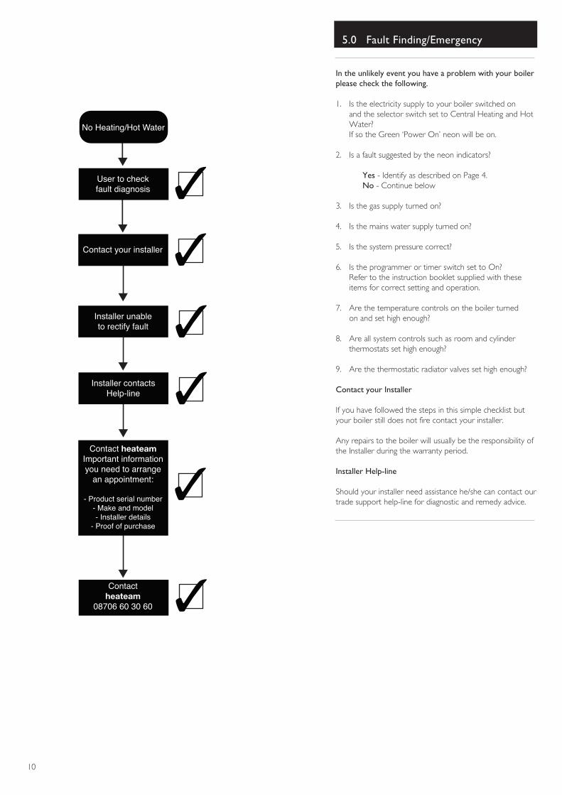
No Heating/Hot Water
User to checkfault diagnosis
Contact your installer
Installer unableto rectify fault
Contact heateamImportant informationyou need to arrange
an appointment:
- Product serial number- Make and model- Installer details
- Proof of purchase
Contactheateam
08706 60 30 60
Installer contactsHelp-line
In the unlikely event you have a problem with your boilerplease check the following.
1. Is the electricity supply to your boiler switched on and the selector switch set to Central Heating and Hot Water?If so the Green ‘Power On’ neon will be on.
2. Is a fault suggested by the neon indicators?
Yes - Identify as described on Page 4.No - Continue below
3. Is the gas supply turned on?
4. Is the mains water supply turned on?
5. Is the system pressure correct?
6. Is the programmer or timer switch set to On? Refer to the instruction booklet supplied with these items for correct setting and operation.
7. Are the temperature controls on the boiler turned on and set high enough?
8. Are all system controls such as room and cylinder thermostats set high enough?
9. Are the thermostatic radiator valves set high enough?
Contact your Installer
If you have followed the steps in this simple checklist butyour boiler still does not fire contact your installer.
Any repairs to the boiler will usually be the responsibility ofthe Installer during the warranty period.
Installer Help-line
Should your installer need assistance he/she can contact ourtrade support help-line for diagnostic and remedy advice.
11
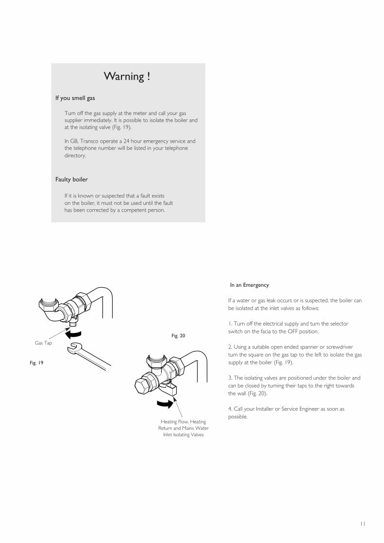
If you smell gas
Turn off the gas supply at the meter and call your gassupplier immediately. It is possible to isolate the boiler andat the isolating valve (Fig. 19).
In GB, Transco operate a 24 hour emergency service andthe telephone number will be listed in your telephonedirectory.
Faulty boiler
If it is known or suspected that a fault exists on the boiler, it must not be used until the fault has been corrected by a competent person.
Warning !
Gas Tap
Heating Flow, HeatingReturn and Mains Water
Inlet Isolating Valves
Fig. 19
Fig. 20
In an Emergency
If a water or gas leak occurs or is suspected, the boiler canbe isolated at the inlet valves as follows;
1. Turn off the electrical supply and turn the selectorswitch on the facia to the OFF position.
2. Using a suitable open ended spanner or screwdriverturn the square on the gas tap to the left to isolate the gassupply at the boiler (Fig. 19).
3. The isolating valves are positioned under the boiler andcan be closed by turning their taps to the right towardsthe wall (Fig. 20).
4. Call your Installer or Service Engineer as soon aspossible.
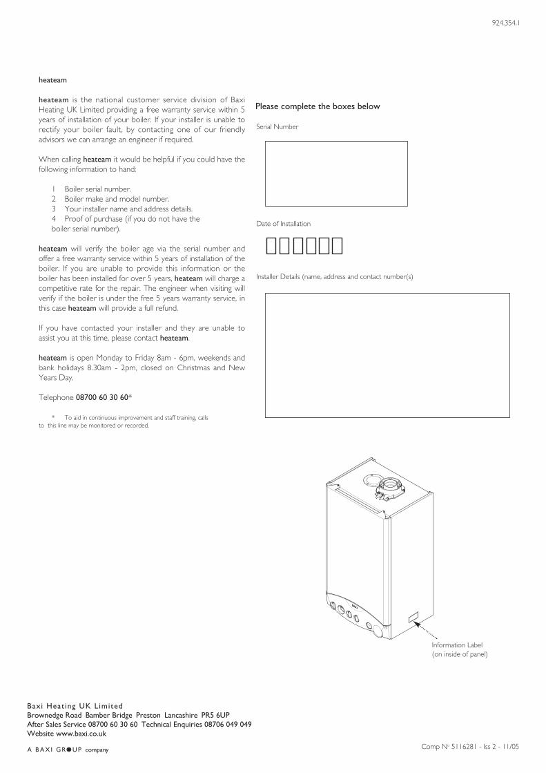
Serial Number
Date of Installation
Installer Details (name, address and contact number(s)
Please complete the boxes below
heateam
heateam is the national customer service division of BaxiHeating UK Limited providing a free warranty service within 5years of installation of your boiler. If your installer is unable torectify your boiler fault, by contacting one of our friendlyadvisors we can arrange an engineer if required.
When calling heateam it would be helpful if you could have thefollowing information to hand:
1 Boiler serial number.2 Boiler make and model number.3 Your installer name and address details.4 Proof of purchase (if you do not have the boiler serial number).
heateam will verify the boiler age via the serial number andoffer a free warranty service within 5 years of installation of theboiler. If you are unable to provide this information or theboiler has been installed for over 5 years, heateam will charge acompetitive rate for the repair. The engineer when visiting willverify if the boiler is under the free 5 years warranty service, inthis case heateam will provide a full refund.
If you have contacted your installer and they are unable toassist you at this time, please contact heateam.
heateam is open Monday to Friday 8am - 6pm, weekends andbank holidays 8.30am - 2pm, closed on Christmas and NewYears Day.
Telephone 08700 60 30 60*
* To aid in continuous improvement and staff training, calls to this line may be monitored or recorded.
Baxi Heat ing UK LimitedBrownedge Road Bamber Bridge Preston Lancashire PR5 6UPAfter Sales Service 08700 60 30 60 Technical Enquiries 08706 049 049Website www.baxi.co.uk
�������Comp No 5116281 - Iss 2 - 11/05
924.354.1
Information Label(on inside of panel)