Embed Size (px)
Citation preview
MD-4221
42” HD MEDICAL LCD MONITOR
User manual

2
3
Copyright notice
This document is copyrighted. All rights are reserved. Nor this document, nor any part of it, may be reproduced or copied in any form or by any means - graphical, electronic, or mechanical including photocopying, taping or information storage and retrieval systems - without written permission of Barco
© 2008 Barco N.V. All rights reserved.
제 품 명 : 42” LCD 모니터 모 델 명 : MD-4221 정격입력 : 100-230V~ 50-60Hz, 3A MAX 제 조 자 : ㈜디앤티 DnT-MD-4221(B) 제조국가 : 대한민국
4
Table of Contents
Table of Contents ....................................................................................... 4 Preface........................................................................................................ 5
Important notice.................................................................................... 5 Environmental information................................................................... 5 Safety Instructions ................................................................................... 6 On Safety ............................................................................................... 6 Caution................................................................................................... 8 FCC Information ................................................................................... 11 Electromagnetic compatibility ............................................................ 13 Recommendations for using your display system............................. 14 Unpacking and handling tips .............................................................. 14 Preventing fire and injury................................................................... 15 Explanation of symbols....................................................................... 15
Introduction.............................................................................................. 17 Quick Startup ....................................................................................... 17 Package Overview............................................................................... 17 Connectors ........................................................................................... 18 Mechanical product drawing .............................................................. 20 Controls................................................................................................ 21 Power management ........................................................................... 23
On-Screen Display Menus........................................................................ 24 OSD functions description........................................................................ 29 Standard signal table ............................................................................... 34
PC modes supported ........................................................................... 34 SDI video format ................................................................................. 35
Signal connector pin assignments .......................................................... 36 Specifications ........................................................................................... 40 BARCO MID GENERAL WARRANTY TERMS AND CONDITIONS ................... 41
5
Preface
Important notice
Notice
Although every attempt has been made to achieve technical accuracy in this document, we assume no responsibility for errors that may be found. Our goal is to provide you with the most accurate and usable documentation possible; if you discover errors, please let us know.
Barco software products are the property of Barco. They are distributed under copyright by Barco N.V., for use only under the specific terms of a software license agreement between Barco N.V. and the licensee. No other use, duplication, or disclosure of a Barco software product, in any form, is authorized.
The specifications of Barco products are subject to change without notice.
Trademarks
All trademarks and registered trademarks are property of their respective owners.
Environmental information
Disposal Information
The lamps inside the display contain mercury. Do not throw the display in the trash. Dispose of it as required by local ordinances or regulations.
This equipment has required the extraction and use of natural resources for its production. It may contain hazardous substances for health and environment.
In order to avoid the dissemination of those substances in the environment and to diminish the pressure on natural resources, we encourage you to use the appropriate take-back systems.
Those systems will reuse or recycle most of the materials of your end-of-life equipment in a sound way.
The crossed-out wheeled bin symbol invites you to use those systems.
If you need more information on the collection, reuse and recycling systems, please contact your local or regional waste administrator.
You can also contact us for more information on the environmental performances of our products.
6
Safety Instructions On Safety
1. Before connecting the AC power cord to the DC adapter outlet make sure the voltage designation of the DC adapter corresponds to the local electrical supply.
2. Never insert anything metallic into the cabinet openings of the Liquid Crystal Display (LCD) monitor. Doing so may create the danger of electric shock.
3. To reduce the risk of electric shock, do not remove cover. No user-serviceable parts inside. Only a qualified technician should open the case of the LCD monitor.
4. Never use your LCD monitor if the power cord has been damaged. Do not allow anything to rest on the power cord, and keep the cord away from areas where people can trip over it.
5. Be sure to hold the plug, not the cord, when disconnecting the LCD monitor from an electric socket.
6. Unplug your LCD monitor when it is going to be left unused for an extended period of time.
7. Unplug your LCD monitor from the AC outlet before any service.
8. If your LCD monitor does not operate normally-in particular, if there are any unusual sounds or smells coming from it, unplug it immediately and contact an authorized dealer or service center.
Warning
Do not to touch signal input, signal output or other connectors, and the patient simultaneously.
Warning
External equipment intended for connection to signal input, signal output or other connectors, shall comply with relevant IEC standard (e.g.,IEC60950 for IT equipment and IEC60601 series for medical electrical equipment).
In addition, all such combinations (systems) shall comply with the standard IEC 60601-1-1, safety requirements for medical electrical systems. Any person who connects has formed at system and is therefore responsible for the system to comply with the requirements of IEC 60601-1-1.
If in doubt, contact a qualified technician or your local sales representative.
7
Warning When necessary, carry this product with at least 2 persons, using both handles on left and right side of the product. If you want the product to be installed on another place, please contact Barco Customer Service center.
On installation 1. Openings in the LCD monitor cabinet are provided for ventilation.
To prevent overheating, these openings should not be blocked or covered. If you put the LCD monitor in a bookcase or some other enclosed space, be sure to provide adequate ventilation.
2. Put your LCD monitor in a location with low humidity and minimal dust.
3. Do not expose the LCD monitor to rain or use it near water (in kitchens, near swimming pools, etc.). If the LCD monitor accidentally gets wet, unplug it and contact an authorized dealer immediately. You can clean the LCD monitor with a damp cloth if necessary, but be sure to unplug the LCD monitor first.
4. Locate your LCD monitor near an easily accessible AC outlet.
5. High temperature can cause problems. Don't use your LCD monitor in direct sunlight and keep it away from heaters, stoves, fireplaces, and sources of heat.
Environmental Conditions for transport and Storage • Temperature range within -20°C to 60°C
• Relative humidity range 10% to 85%
• Atmospheric pressure range within 500 to 1060hPa.
Rapid change in ambient temperature may adversely affect the product.
Allow about 8 hours for the product to reach an ambient temperature for starting use.
Intended Use
This TFT-LCD Monitor is as accessory intended for use with Medical Equipment to display alpha, numerical and graphical data.
8
Caution
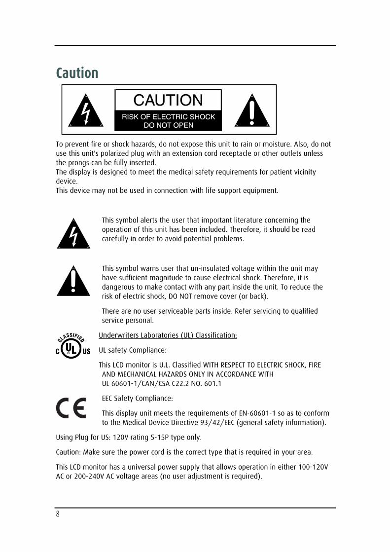
To prevent fire or shock hazards, do not expose this unit to rain or moisture. Also, do not use this unit's polarized plug with an extension cord receptacle or other outlets unless the prongs can be fully inserted. The display is designed to meet the medical safety requirements for patient vicinity device. This device may not be used in connection with life support equipment.
This symbol alerts the user that important literature concerning the operation of this unit has been included. Therefore, it should be read carefully in order to avoid potential problems.
This symbol warns user that un-insulated voltage within the unit may have sufficient magnitude to cause electrical shock. Therefore, it is dangerous to make contact with any part inside the unit. To reduce the risk of electric shock, DO NOT remove cover (or back).
There are no user serviceable parts inside. Refer servicing to qualified service personal.
Underwriters Laboratories (UL) Classification:
UL safety Compliance:
This LCD monitor is U.L. Classified WITH RESPECT TO ELECTRIC SHOCK, FIRE AND MECHANICAL HAZARDS ONLY IN ACCORDANCE WITH UL 60601-1/CAN/CSA C22.2 NO. 601.1
EEC Safety Compliance:
This display unit meets the requirements of EN-60601-1 so as to conform to the Medical Device Directive 93/42/EEC (general safety information).
Using Plug for US: 120V rating 5-15P type only.
Caution: Make sure the power cord is the correct type that is required in your area.
This LCD monitor has a universal power supply that allows operation in either 100-120V AC or 200-240V AC voltage areas (no user adjustment is required).
9
Use the proper power cord with correct attachment plug type. If the power source is 120V AC, use a power cord which is a Hospital Grade Power Cord with NEMA 5-15 style plug, labeled for 125 volts AC with UL and C-UL approvals. If the power source is a 240 V AC supply, use the tandem (T blade) type attachment plug with ground conductor power cord that meets the respective European country's safety regulations.
The hospital-grade plug for medical products intended for use in Denmark has DEMKO approval and is rated 13 amps at 250Vac. Plug is recommended for use in medical applications and specifications are being added to the standard S B 107-2-D1. Plug mates with maker's Danish hospital-grade socket. Hospital sockets have slightly different shaped openings allowing only the hospital plug, not the standard Danish plug, to be inserted, to protect the ac circuit in specific medical settings.
Cleaning Instructions
Follow your hospital protocol for the handling of blood and body fluids. Clean the display with a diluted mixture of mild detergent and water. Use a soft towel or swab.
Use of certain cleaning agents may cause degradation to the labels and plastic components of the product.
Consult cleanser manufacturer to see if agent is compatible with it. Do not allow liquid enter the display.
Maintenance
Replacing the Fuses:
To avoid the risk of fire, use only fuses of the value specified on the fuse label located on the rear panel.
• Unplug the power cord from the wall outlet.
• Unlatch the fuse holder above the AC inlet and remove it. (You may need to press the tab on the fuse holder with a slender screwdriver to release the latch)
• Replace the fuse with the same value and rating.
• Reinstall the fuse holder until the tab snaps in place.
10
Servicing
Do not attempt to service the apparatus yourself as opening or removing covers may expose you to dangerous voltages or other hazards, and will void the warranty.
Refer all servicing to qualified service personnel.
Unplug the apparatus from its power source and refer servicing to qualified personnel under the following conditions:
• If the power cord or plug is damaged or frayed.
• If liquid has been spilled into the apparatus.
• If objects have fallen into the apparatus.
• If the apparatus has been exposed to rain or moisture.
• If the apparatus has been subjected to excessive shock by being dropped.
• If the cabinet has been damaged.
• If the apparatus seems to be overheated.
• If the apparatus emits smoke or abnormal odor.
• If the apparatus fails to operate in accordance with the operating instructions.
Accessories
Use only accessories specified by the manufacturer, or sold with the apparatus.
Classification • Protection against electric shock : Class I
• Applied Parts : No Applied Parts
• Protection against harmful ingress of water : IPX1
• Degree of safety in the presence of flammable anesthetics mixture with air or with oxygen or with nitrous oxide: Not suitable for use in the presence of a flammable anesthetics mixture with oxygen or with nitrous oxide.
• Mode of operation: Continuous.
.
11
FCC Information
This equipment has been tested and found to comply with the limits of a Class B digital device, pursuant to Part 15 of the FCC Rules.
These limits are designed to provide reasonable protection against interference. This monitor can radiate radio frequency energy and, if not installed and used in accordance with the instructions, it may interfere with other radio communications equipment. There is no guarantee that interference will not occur in a particular installation.
If this equipment is found to cause harmful interference to radio or television reception, the user is encouraged to try to correct the interference by carrying out one or more of the following measures:
1. Reorient or relocate the receiving antenna.
2. Increase the distance between the color monitor and the subject of interference.
3. Plug the monitor into an outlet on a different electrical circuit than the one to which the subject of interference is connected.
4. Consult the dealer or an experienced radio/TV technician for help.
NOTICES TO THE USER:
This device complies with part 15 of the FCC Rules. Operation is subject to the following two conditions:
(1) this device may not cause harmful interference, and (2) this device must accept any interference received, including interference that may cause undesired operation.
FCC WARNING:
This equipment generates or uses radio frequency energy. Changes or modifications to this equipment may cause harmful interference unless the modifications are expressly approved in the instruction manual. The user could lose authority to operate this equipment if an unauthorized change or modification is made.
1. Guidance and manufacturer's declaration - electromagnetic emissions
The MD-4221 is intended for use in the electromagnetic environment specified below. The customer or the user of the MD-4221 should assure that it is used in such an environment.
Emission test
Compliance Electromagnetic environment -guidance
RF Emissions CISPR 11
Group 1 MD-4221 is suitable for use in all establishments,
12
RF Emissions CISPR 11
Class B
Harmonic emissions IEC 61000-3-2
D
Voltage fluctuations IEC 61000-3-3
Complies
including domestic establishments and those directly connected to the public low-voltage power supply network that supplies buildings used for domestic purposes
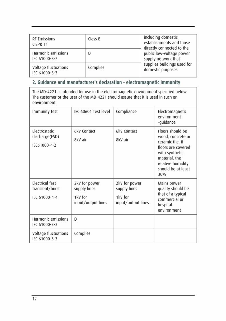
2. Guidance and manufacturer's declaration - electromagnetic immunity
The MD-4221 is intended for use in the electromagnetic environment specified below. The customer or the user of the MD-4221 should assure that it is used in such an environment.
Immunity test
IEC 60601 Test level Compliance Electromagnetic environment -guidance
Electrostatic discharge(ESD)
IEC61000-4-2
6kV Contact
8kV air
6kV Contact
8kV air
Floors should be wood, concrete or ceramic tile. If floors are covered with synthetic material, the relative humidity should be at least 30%
Electrical fast transient/burst
IEC 61000-4-4
2kV for power supply lines
1kV for input/output lines
2kV for power supply lines
1kV for input/output lines
Mains power quality should be that of a typical commercial or hospital environment
Harmonic emissionsIEC 61000-3-2
D
Voltage fluctuationsIEC 61000-3-3
Complies
13
Electromagnetic compatibility
Warning
When this device is connected with other electrical equipment, leakage currents may be additive. To minimize total leakage current per patient, ensure that all systems are installed according to the requirements of IEC 60601-1-1.
Caution
Portable and mobile RF communications equipment may affect the normal function of the display. Do not use cables or accessories other than those provided with the display, as this may result in increased electromagnetic emissions or decreased immunity to such emissions. If the display is used adjacent to other equipment, observe and verify normal operation of the display in the configuration in which it will be used prior to using it in a surgical procedure. Consult the tables below for guidance in placing the display.
Like other electrical medical equipment, the MD-4221 requires special precautions to ensure electromagnetic compatibility with other electrical medical devices. To ensure electromagnetic compatibility (EMC), the display must be installed and operated according to the EMC information provided in this manual. The display have been designed and tested to comply with IEC 60601-1-2:2001 requirements for EMC with other devices.
14
Recommendations for using your display system
1. Optimize the lifetime of your display
Enabling the Display Power Management System (DPMS) of your display (in the display’s Settings menu) will optimize LCD backlight lifetime by automatically switching off the backlight when the display is not used for a specified period of time. By default, DPMS is enabled on your display, but it also needs to be activated on your workstation. To do this, go to “Power Options Properties” in the “Control Panel”.
Barco recommends setting DPMS activation after 20 minutes of non-usage.
2. Use a screen saver to avoid image retention
Prolonged operation of an LCD with the same content on the same screen area may result in a form of image retention.
You can avoid or significantly reduce the occurrence of this phenomenon by using a screen saver. You can activate a screen saver in the “Display properties” window of your workstation.
Barco recommends setting screen saver activation after 5 minutes of non-usage. A good screen saver displays moving content.
In case you are working with the same image or an application with static image elements for several hours continuously (so that the screen saver is not activated), change the image content regularly to avoid image retention of the static elements.
3. Understand pixel technology
LCD displays use technology based on pixels. As a normal tolerance in the manufacturing of the LCD, a limited number of these pixels may remain either dark or permanently lit, without affecting the diagnostic performance of the product. To ensure optimal product quality, Barco applies strict selection criteria for its LCD panels.
To learn more about LCD technology and missing pixels, consult the dedicated white paper available at www.barcomedical.com.
Unpacking and handling tips
The display is a precision instrument that requires proper care to maintain product operation and adherence to specification. Unpack the display and components carefully, then set up and handle the unit properly to avoid damage to the LCD panel.
• Always lift and carry the display with 2 persons.
• Use both hands to grasp the display case when lifting it from the shipping carton, but avoid touching the screen.
15
• Do not apply pressure to the screen or touch the screen with bare fingers or objects. Pressure can affect image quality. Cosmetics and oils on the skin are both detrimental to the screen and difficult to remove.
• Allow the display to warm up to room temperature before turning it on. Avoid sudden temperature changes in the environment, as this may cause condensation, which damages the display.
• Do not set up the display near strong light or heat sources.
• Do not block the vents on the back of the display or install the display in a built-in enclosure. Blocked vents cause excessive heat to build up inside the display, increasing risk of fire.
• When installing components, turn off your computer, but leave it plugged into a grounded outlet.
• Do not remove the back cover or disassemble the display. There are no user-serviceable parts inside.
Preventing fire and injury
• Replace the power supply cables if damaged.
• Use only the power source indicated in this guide or listed on the display.
• Do not plug the power supply into an overloaded AC outlet or extension cord. Overloaded AC outlets and cords can result in electric shock or fire.
• Do not drop or push objects into the display case. Internal components contain high voltage.
• Unplug the power cord from the wall outlet during thunderstorms.
• Do not place magnetic devices, such as motors, near the display.
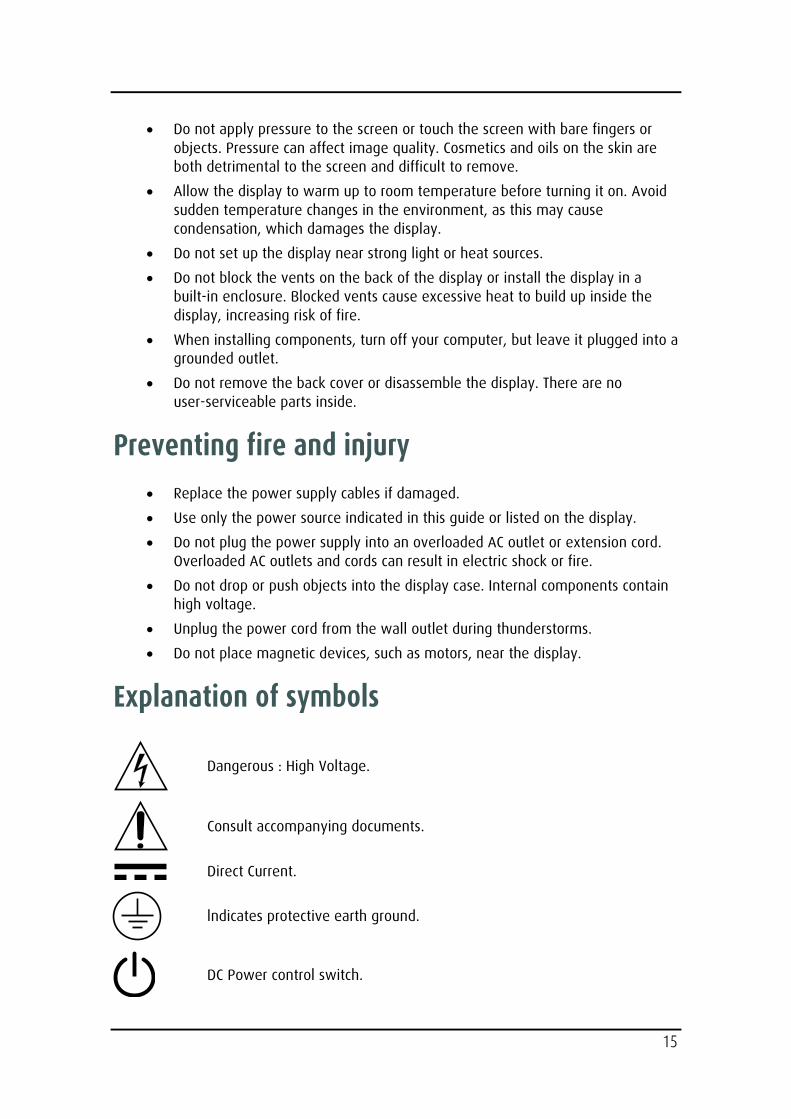
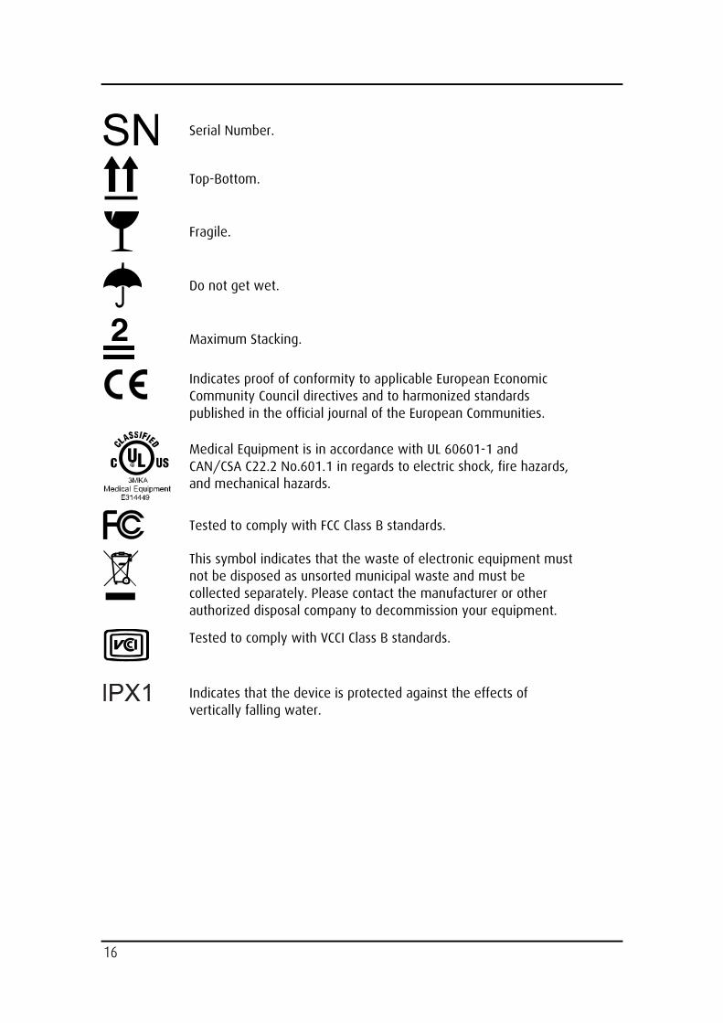
Explanation of symbols
Dangerous : High Voltage.
Consult accompanying documents.
Direct Current.
lndicates protective earth ground.
DC Power control switch.
16
Serial Number.
Top-Bottom.
Fragile.
Do not get wet.
Maximum Stacking.
Indicates proof of conformity to applicable European Economic Community Council directives and to harmonized standards published in the official journal of the European Communities.
Medical Equipment is in accordance with UL 60601-1 and CAN/CSA C22.2 No.601.1 in regards to electric shock, fire hazards, and mechanical hazards.
Tested to comply with FCC Class B standards.
This symbol indicates that the waste of electronic equipment must not be disposed as unsorted municipal waste and must be collected separately. Please contact the manufacturer or other authorized disposal company to decommission your equipment.
Tested to comply with VCCI Class B standards.
Indicates that the device is protected against the effects of vertically falling water.
17
Introduction
Quick Startup
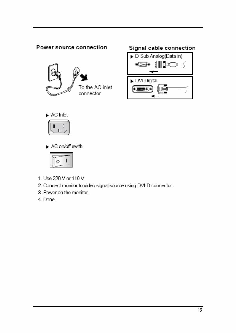
1. Connect the power supply to the display via the power plug.
2. Plug into the AC inlet with power cord cable.
3. Connect the video source to this monitor.
4. Apply power to the peripheral device.
5. Turn on the switch of this monitor.
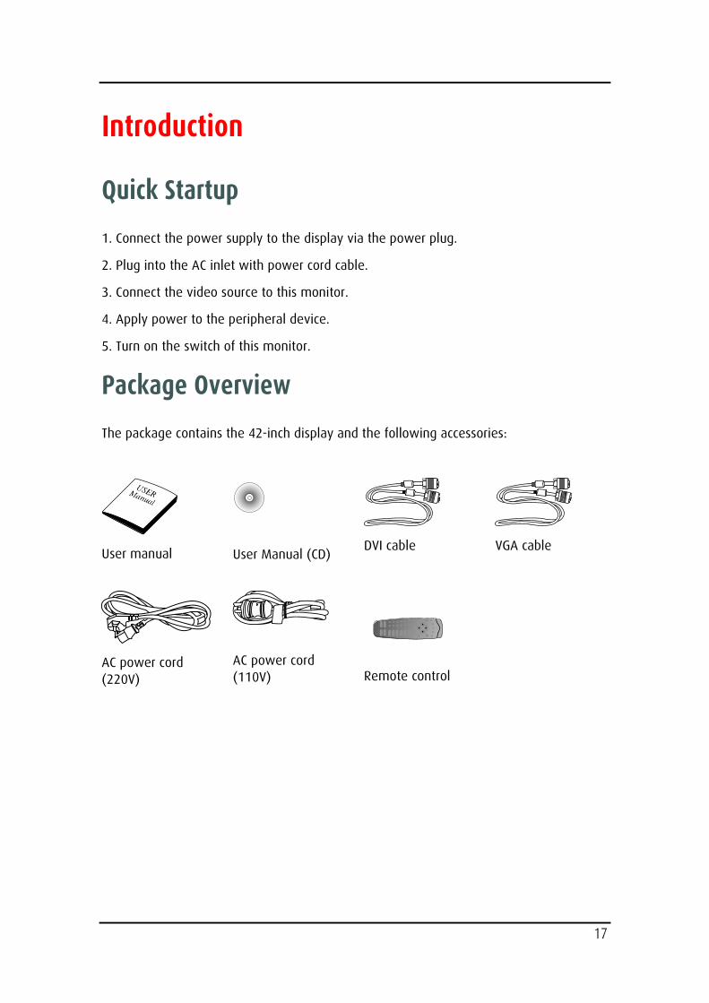
Package Overview
The package contains the 42-inch display and the following accessories:
User manual
User Manual (CD)
DVI cable
VGA cable
AC power cord (220V)
AC power cord (110V)
Remote control
18
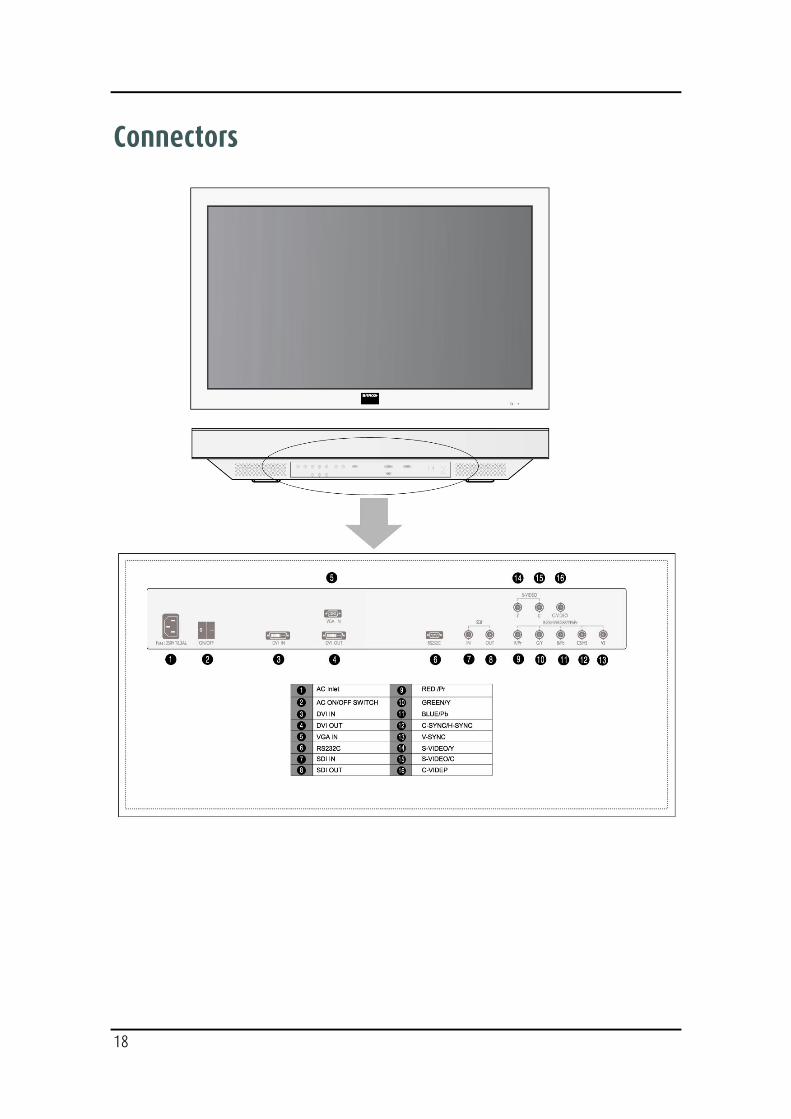
Connectors
19
20
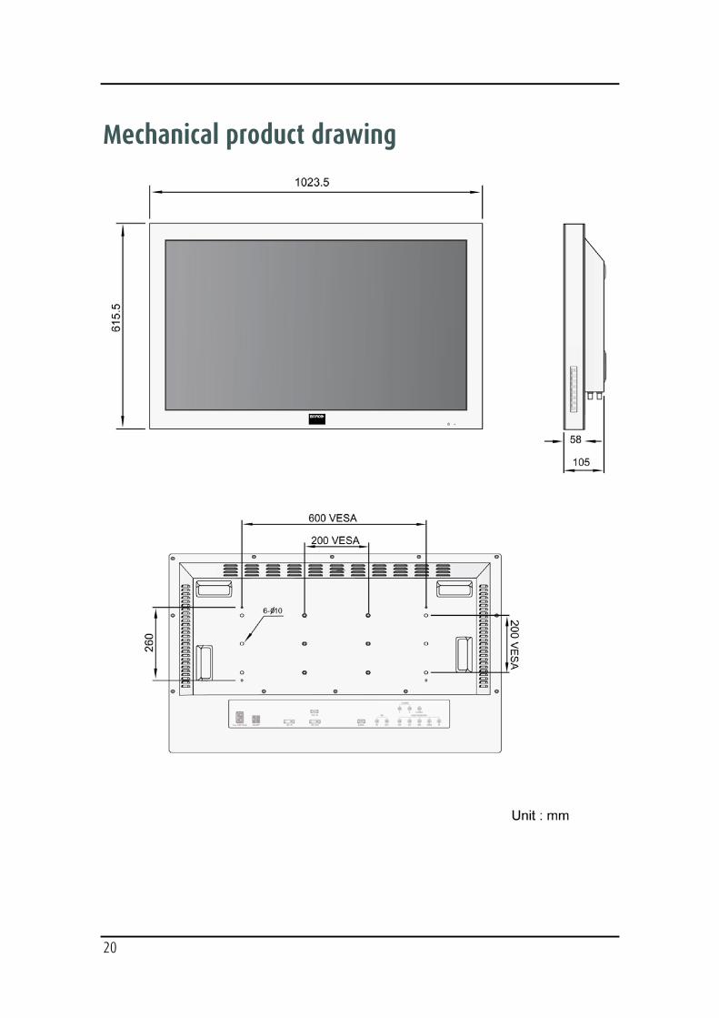
Mechanical product drawing
21
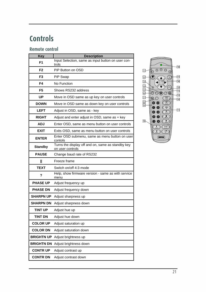
Controls Remote control
Key Description
F1 Input Selection, same as input button on user con-trols
F2 PiP Button on OSD
F3 PiP Swap
F4 No Function
F5 Shows RS232 address
UP Move in OSD same as up key on user controls
DOWN Move in OSD same as down key on user controls
LEFT Adjust in OSD, same as - key
RIGHT Adjust and enter adjust in OSD, same as + key
ADJ Enter OSD, same as menu button on user controls
EXIT Exits OSD, same as menu button on user controls
ENTER Enter OSD submenu, same as menu button on user contols
Standby Turns the display off and on, same as standby key on user controls
PAUSE Change baud rate of RS232
|| Freeze frame
TEXT Switch on/off 4:3 mode
? Help, show firmware version - same as with service menu
PHASE UP Adjust frequency up
PHASE DN Adjust frequency down
SHARPN UP Adjust sharpness up
SHARPN DN Adjust sharpness down
TINT UP Adjust hue up
TINT DN Adjust hue down
COLOR UP Adjust saturation up
COLOR DN Adjust saturation down
BRIGHTN UP Adjust brightness up
BRIGHTN DN Adjust brightness down
CONTR UP Adjust contrast up
CONTR DN Adjust contrast down
22
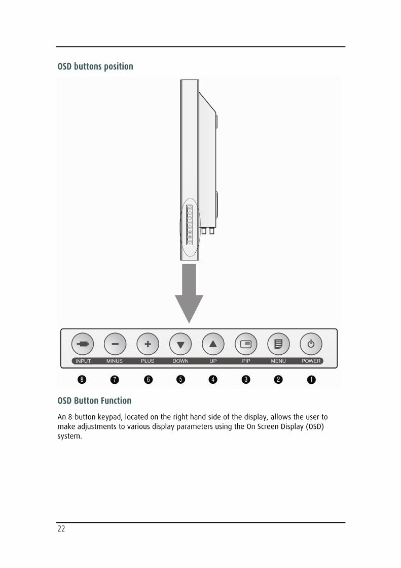
OSD buttons position
OSD Button Function
An 8-button keypad, located on the right hand side of the display, allows the user to make adjustments to various display parameters using the On Screen Display (OSD) system.
23
● Power LED
Green : Normal mode
Amber: Standby mode
Amber: Soft power-off
● On-Screen Display (OSD) Function Button
1. POWER : Turns ON/OFF the monitor.
2. MENU : With OSD deactivated, Activate the OSD menu. With OSD activated, Exit from main menu or sub menu.
3. PIP : With OSD deactivated, Hot key of PIP mode.
4. UP : With OSD deactivated, Hot key of the brightness control and increases the brightness. With OSD activated, move the cursor upward.
5. DOWN : With OSD deactivated, Hot key of the brightness control and decreases the brightness. With OSD activated, move the cursor downward.
6. MINUS : With OSD deactivated, Hot key of the contrast control and decreases the contrast. With OSD activated, decreases the adjustment of the selected function.
7. PLUS : With OSD deactivated, Hot key of the contrast control and increase the contrast. With OSD activated, enter sub menu and increases the adjustment of the selected function.
8. INPUT : Change the display signal source. If VGA Analog's picture size not matched with full screen size or image is noisy press the input button during 2~3 seconds then you can see the most appropriate screen.
Power management
This monitor does not adhere to the VESA DPMS standard when no signal is present on the video inputs.
Status LED sign Power Consumption
Normal Mode Green on <260W
Standby Mode Amber <17W
Soft power-off Amber <14W
24
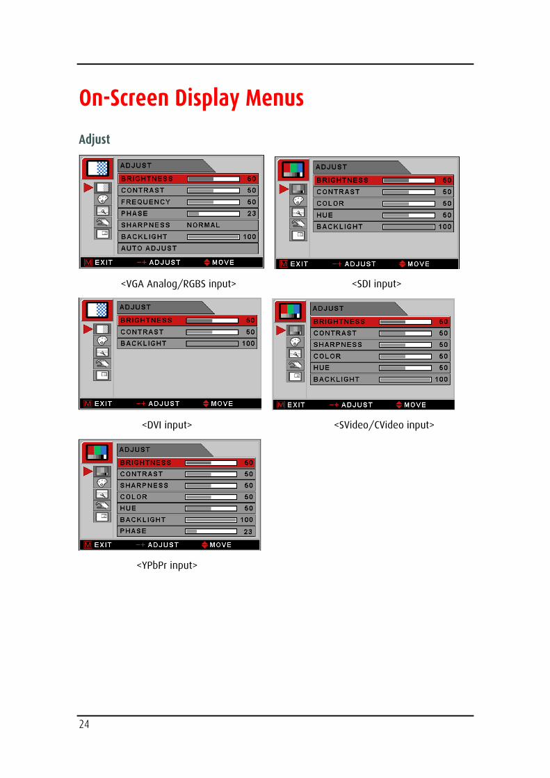
On-Screen Display Menus
Adjust
<VGA Analog/RGBS input> <SDI input>
<DVI input> <SVideo/CVideo input>
<YPbPr input>
25
BRIGHTNESS Increase or decrease the brightness. (Range : 0~100)
CONTRAST Increase or decrease the Contrast. (Range : 0~100)
SHARPNESS (1) Adjusts the sharpness of video image. (Range : 0~100)
SHARPNESS (2) Adjusts the sharpness of video image. (SOFTEST, SOFT, NORMAL, SHARP, SHARPEST)
COLOR (3) Changes the color value. (Range : 0~100)
HUE (3) Changes the Hue. (Range : 0~100)
BACKLIGHT Adjusts backlight dimming level. (Range : 0~100)
PHASE (4) Adjust backlight dimming level. (Range : 0~100)
FREQUENCY (4) Increase or decrease the sampling frequency. (Range : 0~100)
AUTO ADJUST (5) Fit to the most appropriate screen on the VGA Analog signal
(1): Available only for YPbPr, SVideo/CVideo input sources
(2): Available only for VGA Analog/RGBS and DVI input sources
(3): Not available for VGA Analog/RGBS and DVI input sources
(4): Not available for DVI, SVideo/Cvideo and SDI input sources
(5): Available only for VGA Analog/RGBS input sources
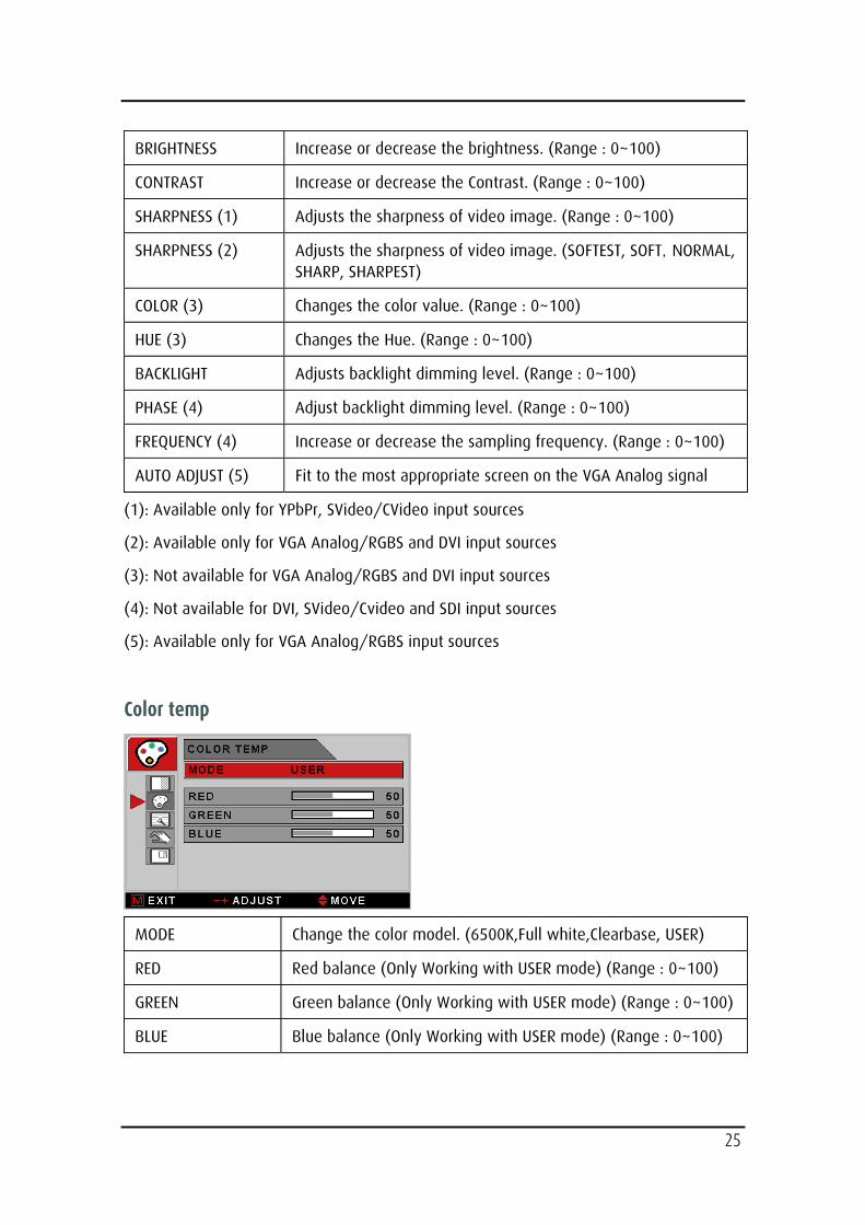
Color temp
MODE Change the color model. (6500K,Full white,Clearbase, USER)
RED Red balance (Only Working with USER mode) (Range : 0~100)
GREEN Green balance (Only Working with USER mode) (Range : 0~100)
BLUE Blue balance (Only Working with USER mode) (Range : 0~100)
26
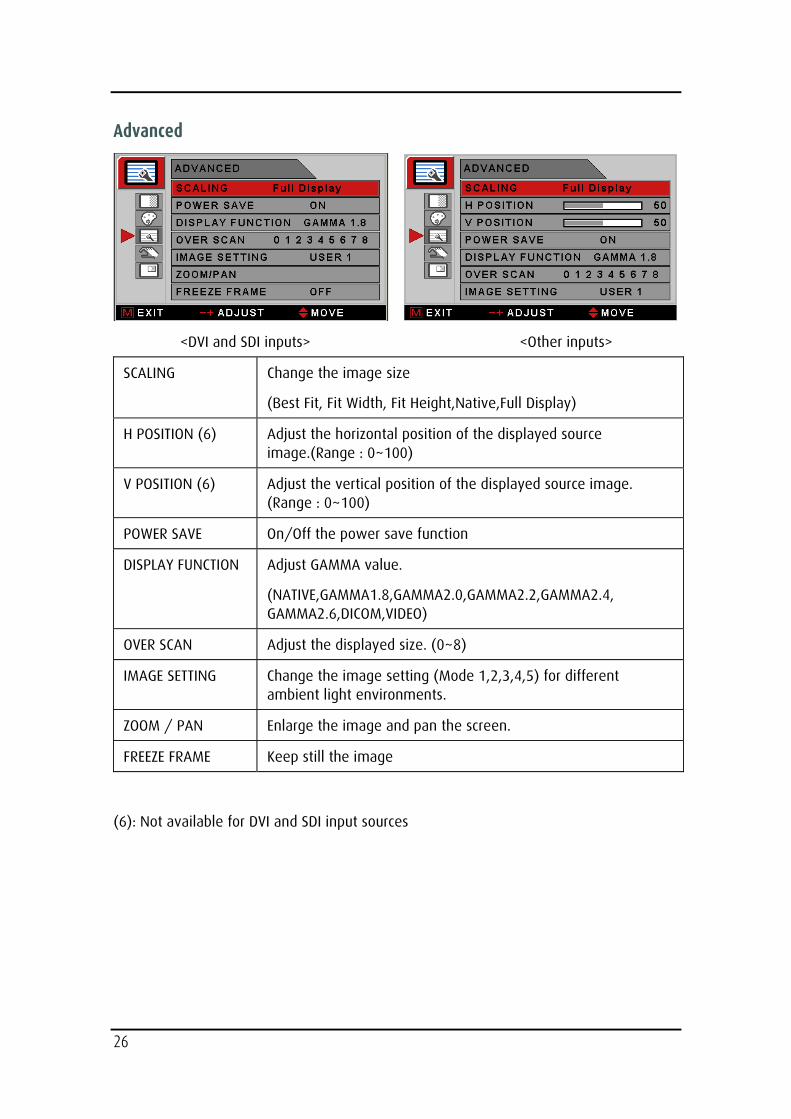
Advanced
<DVI and SDI inputs> <Other inputs>
SCALING Change the image size
(Best Fit, Fit Width, Fit Height,Native,Full Display)
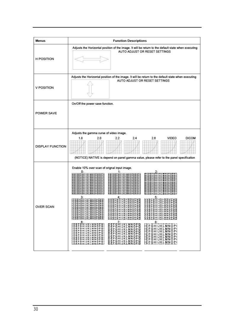
H POSITION (6) Adjust the horizontal position of the displayed source image.(Range : 0~100)
V POSITION (6) Adjust the vertical position of the displayed source image. (Range : 0~100)
POWER SAVE On/Off the power save function
DISPLAY FUNCTION Adjust GAMMA value.
(NATIVE,GAMMA1.8,GAMMA2.0,GAMMA2.2,GAMMA2.4, GAMMA2.6,DICOM,VIDEO)
OVER SCAN Adjust the displayed size. (0~8)
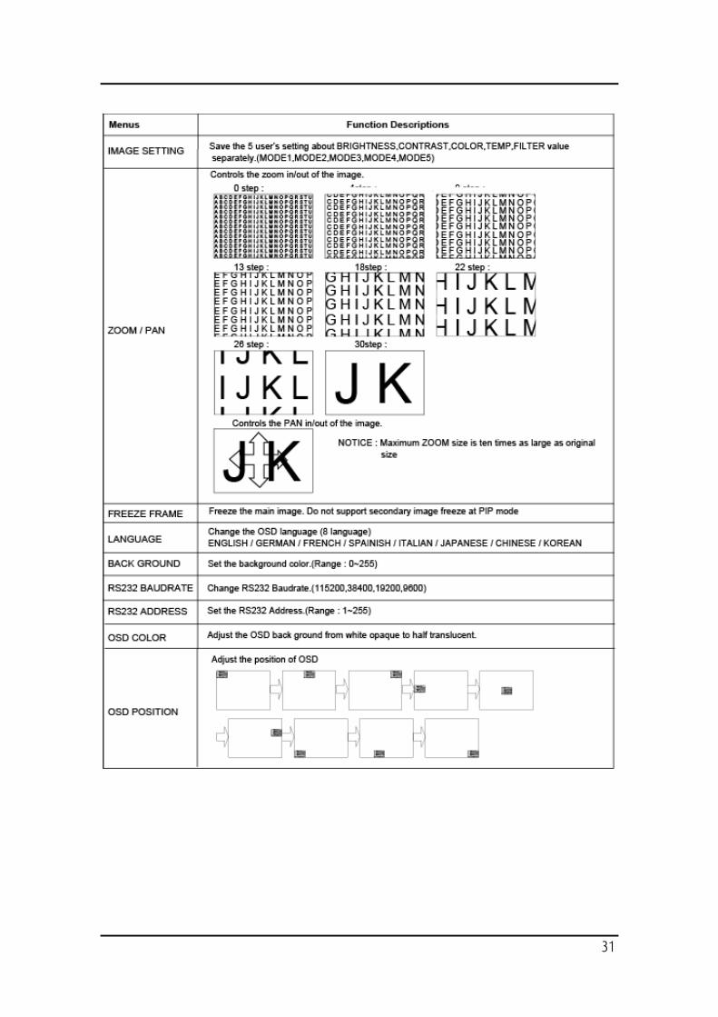
IMAGE SETTING Change the image setting (Mode 1,2,3,4,5) for different ambient light environments.
ZOOM / PAN Enlarge the image and pan the screen.
FREEZE FRAME Keep still the image
(6): Not available for DVI and SDI input sources
27
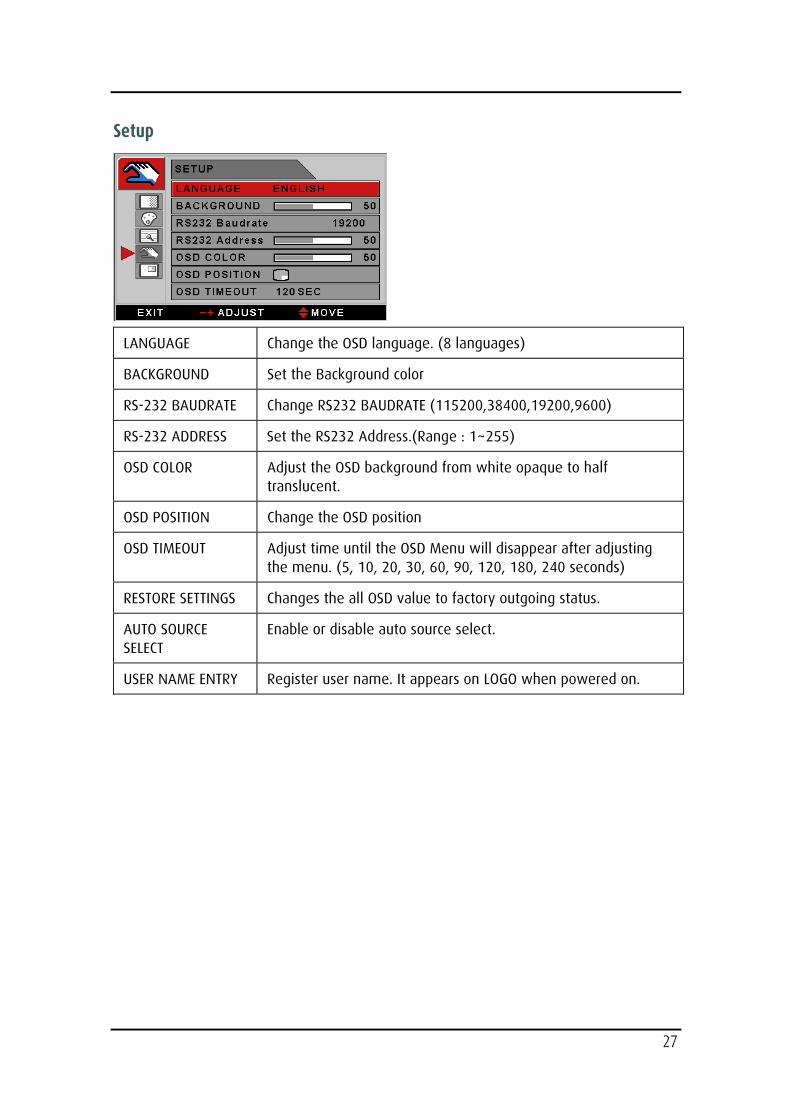
Setup
LANGUAGE Change the OSD language. (8 languages)
BACKGROUND Set the Background color
RS-232 BAUDRATE Change RS232 BAUDRATE (115200,38400,19200,9600)
RS-232 ADDRESS Set the RS232 Address.(Range : 1~255)
OSD COLOR Adjust the OSD background from white opaque to half translucent.
OSD POSITION Change the OSD position
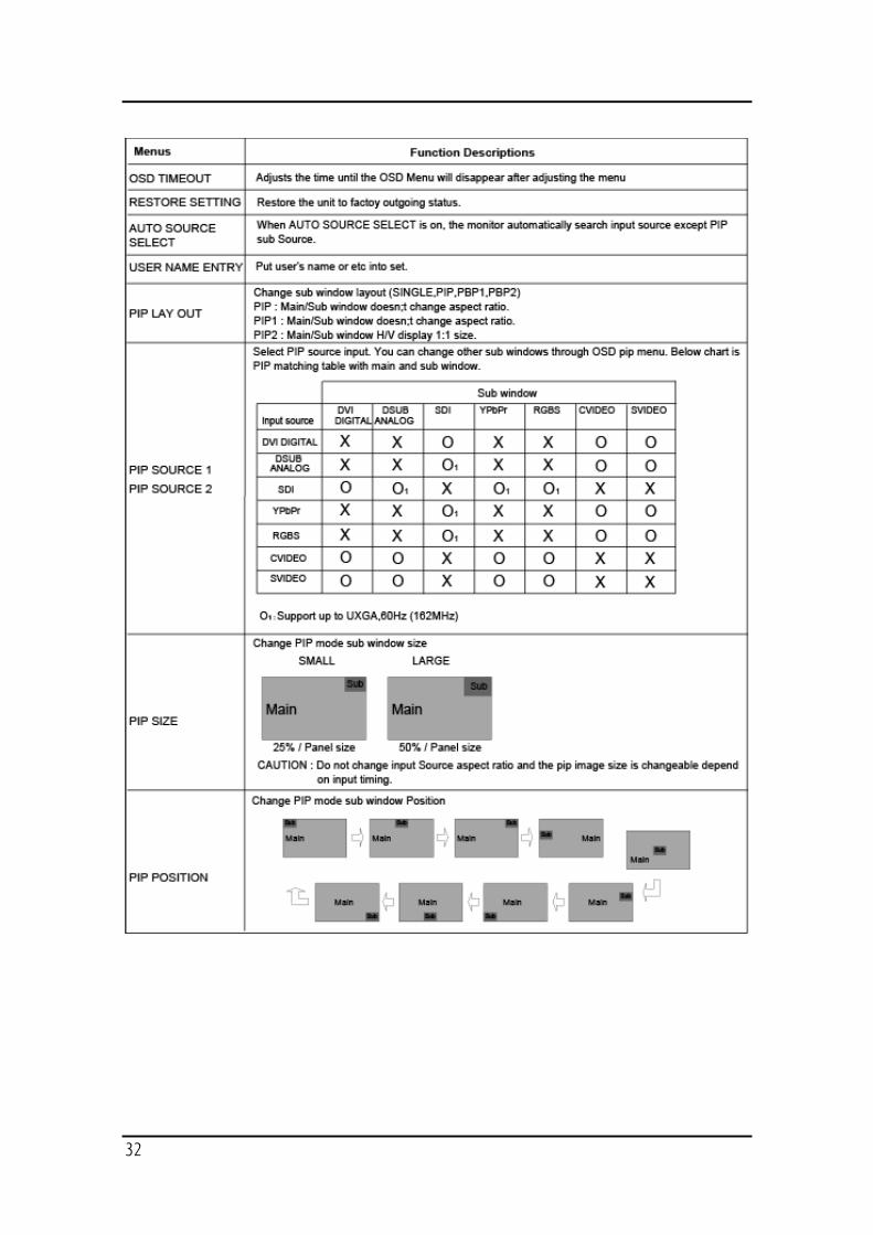
OSD TIMEOUT Adjust time until the OSD Menu will disappear after adjusting the menu. (5, 10, 20, 30, 60, 90, 120, 180, 240 seconds)
RESTORE SETTINGS Changes the all OSD value to factory outgoing status.
AUTO SOURCE SELECT
Enable or disable auto source select.
USER NAME ENTRY Register user name. It appears on LOGO when powered on.
28
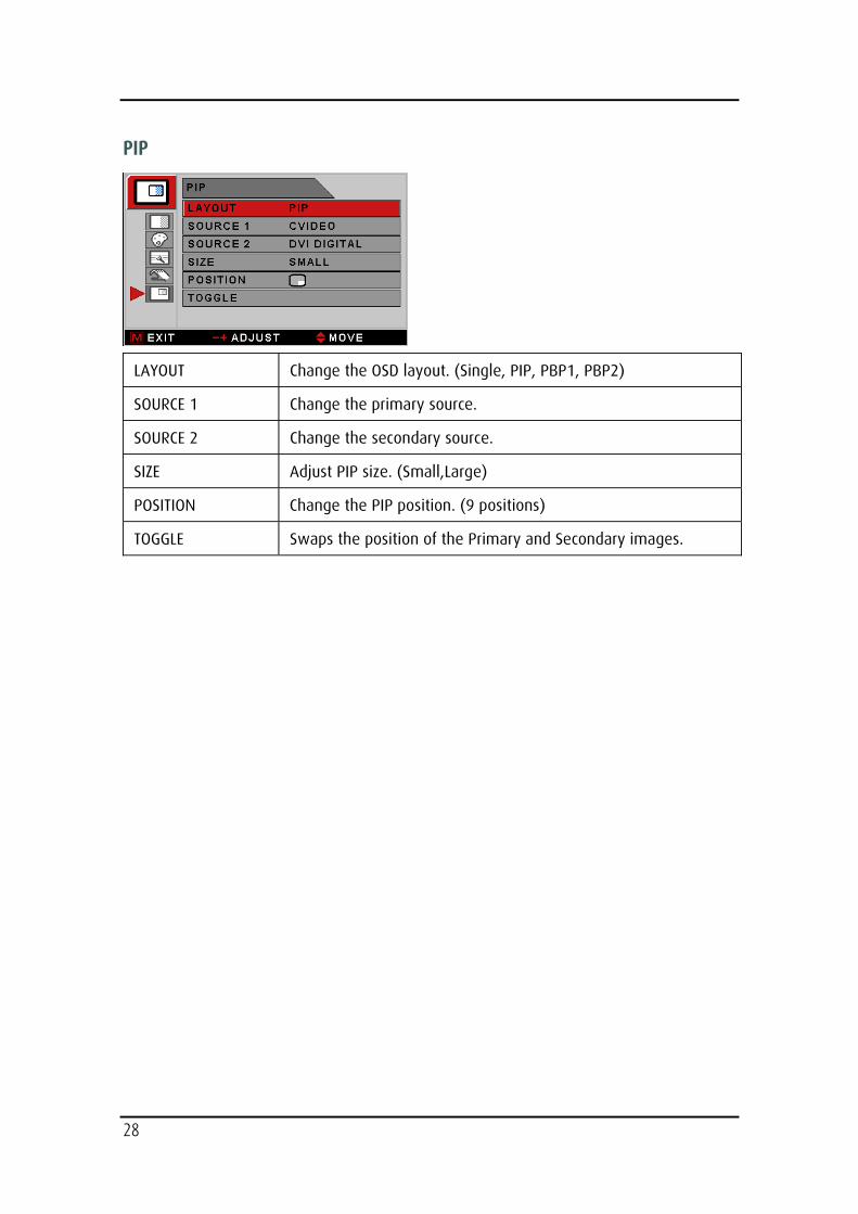
PIP
LAYOUT Change the OSD layout. (Single, PIP, PBP1, PBP2)
SOURCE 1 Change the primary source.
SOURCE 2 Change the secondary source.
SIZE Adjust PIP size. (Small,Large)
POSITION Change the PIP position. (9 positions)
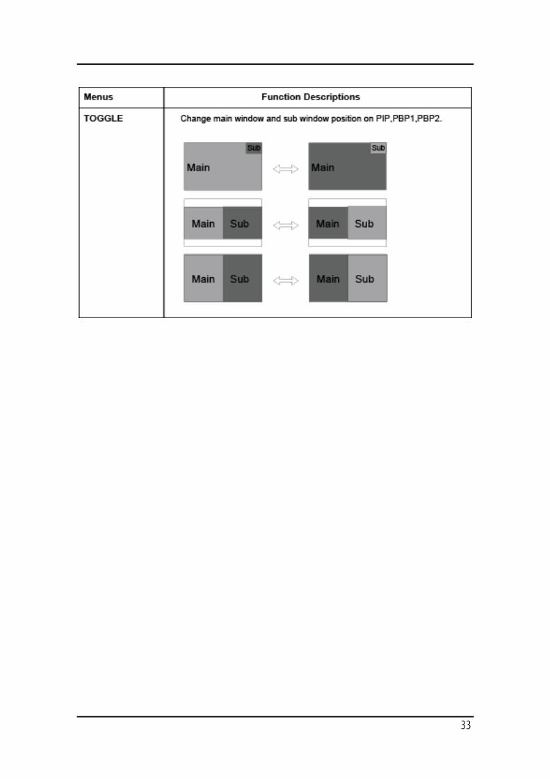
TOGGLE Swaps the position of the Primary and Secondary images.
29
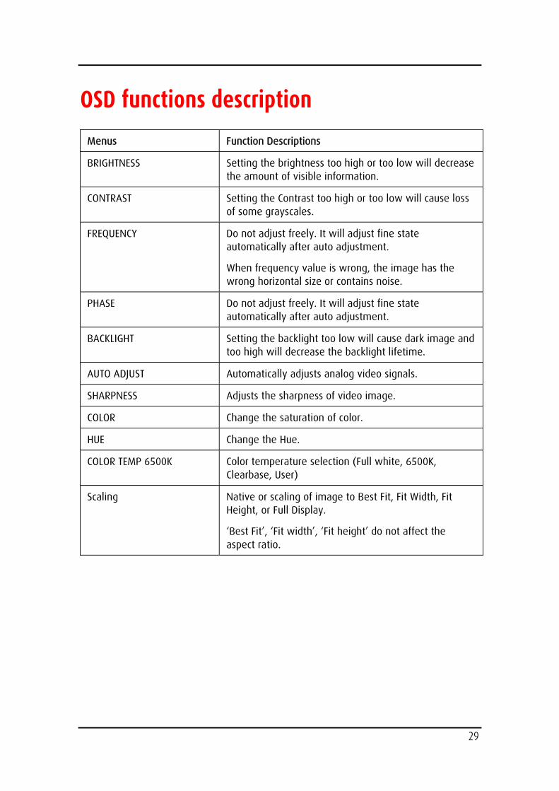
OSD functions description
Menus Function Descriptions
BRIGHTNESS Setting the brightness too high or too low will decrease the amount of visible information.
CONTRAST Setting the Contrast too high or too low will cause loss of some grayscales.
FREQUENCY Do not adjust freely. It will adjust fine state automatically after auto adjustment.
When frequency value is wrong, the image has the wrong horizontal size or contains noise.
PHASE Do not adjust freely. It will adjust fine state automatically after auto adjustment.
BACKLIGHT Setting the backlight too low will cause dark image and too high will decrease the backlight lifetime.
AUTO ADJUST Automatically adjusts analog video signals.
SHARPNESS Adjusts the sharpness of video image.
COLOR Change the saturation of color.
HUE Change the Hue.
COLOR TEMP 6500K Color temperature selection (Full white, 6500K, Clearbase, User)
Scaling Native or scaling of image to Best Fit, Fit Width, Fit Height, or Full Display.
‘Best Fit’, ‘Fit width’, ‘Fit height’ do not affect the aspect ratio.
30
31
32
33
34
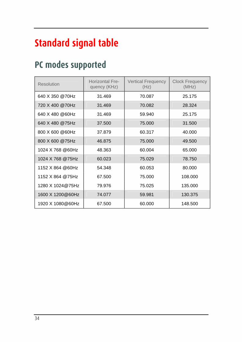
Standard signal table
PC modes supported
Resolution Horizontal Fre-quency (KHz)
Vertical Frequency (Hz)
Clock Frequency (MHz)
640 X 350 @70Hz 31.469 70.087 25.175
720 X 400 @70Hz 31.469 70.082 28.324
640 X 480 @60Hz 31.469 59.940 25.175
640 X 480 @75Hz 37.500 75.000 31.500
800 X 600 @60Hz 37.879 60.317 40.000
800 X 600 @75Hz 46.875 75.000 49.500
1024 X 768 @60Hz 48.363 60.004 65.000
1024 X 768 @75Hz 60.023 75.029 78.750
1152 X 864 @60Hz 54.348 60.053 80.000
1152 X 864 @75Hz 67.500 75.000 108.000
1280 X 1024@75Hz 79.976 75.025 135.000
1600 X 1200@60Hz 74.077 59.981 130.375
1920 X 1080@60Hz 67.500 60.000 148.500
35
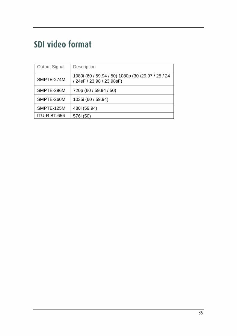
SDI video format
Output Signal Description
SMPTE-274M 1080i (60 / 59.94 / 50) 1080p (30 /29.97 / 25 / 24 / 24sF / 23.98 / 23.98sF)
SMPTE-296M 720p (60 / 59.94 / 50)
SMPTE-260M 1035i (60 / 59.94)
SMPTE-125M 480i (59.94) ITU-R BT.656 576i (50)
36
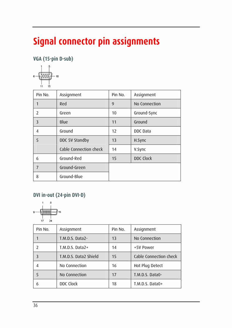
Signal connector pin assignments
VGA (15-pin D-sub)
Pin No. Assignment Pin No. Assignment
1 Red 9 No Connection
2 Green 10 Ground-Sync
3 Blue 11 Ground
4 Ground 12 DDC Data
5 DDC 5V Standby 13 H.Sync
Cable Connection check 14 V.Sync
6 Ground-Red 15 DDC Clock
7 Ground-Green
8 Ground-Blue
DVI in-out (24-pin DVI-D)
Pin No. Assignment Pin No. Assignment
1 T.M.D.S. Data2- 13 No Connection
2 T.M.D.S. Data2+ 14 +5V Power
3 T.M.D.S. Data2 Shield 15 Cable Connection check
4 No Connection 16 Hot Plug Detect
5 No Connection 17 T.M.D.S. Data0-
6 DDC Clock 18 T.M.D.S. Data0+
37
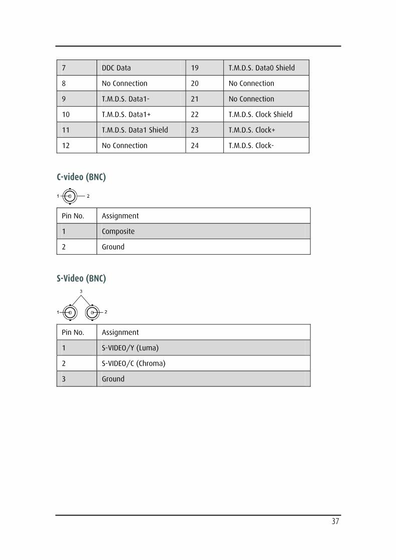
7 DDC Data 19 T.M.D.S. Data0 Shield
8 No Connection 20 No Connection
9 T.M.D.S. Data1- 21 No Connection
10 T.M.D.S. Data1+ 22 T.M.D.S. Clock Shield
11 T.M.D.S. Data1 Shield 23 T.M.D.S. Clock+
12 No Connection 24 T.M.D.S. Clock-
C-video (BNC)
Pin No. Assignment
1 Composite
2 Ground
S-Video (BNC)
Pin No. Assignment
1 S-VIDEO/Y (Luma)
2 S-VIDEO/C (Chroma)
3 Ground
38
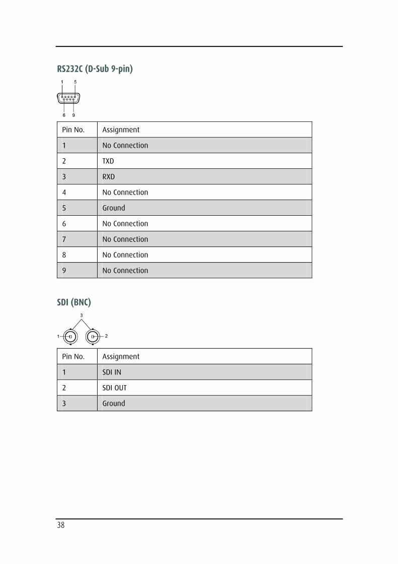
RS232C (D-Sub 9-pin)
Pin No. Assignment
1 No Connection
2 TXD
3 RXD
4 No Connection
5 Ground
6 No Connection
7 No Connection
8 No Connection
9 No Connection
SDI (BNC)
Pin No. Assignment
1 SDI IN
2 SDI OUT
3 Ground
39
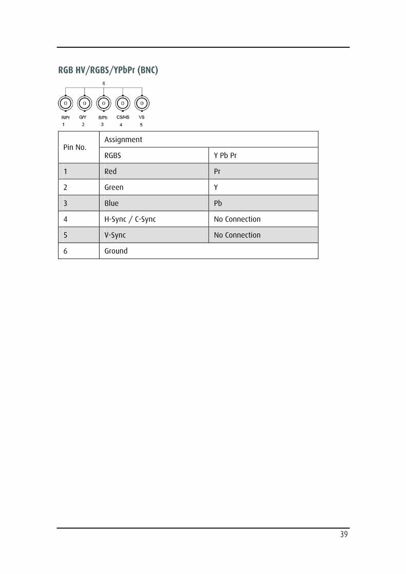
RGB HV/RGBS/YPbPr (BNC)
Assignment Pin No.
RGBS Y Pb Pr
1 Red Pr
2 Green Y
3 Blue Pb
4 H-Sync / C-Sync No Connection
5 V-Sync No Connection
6 Ground
40
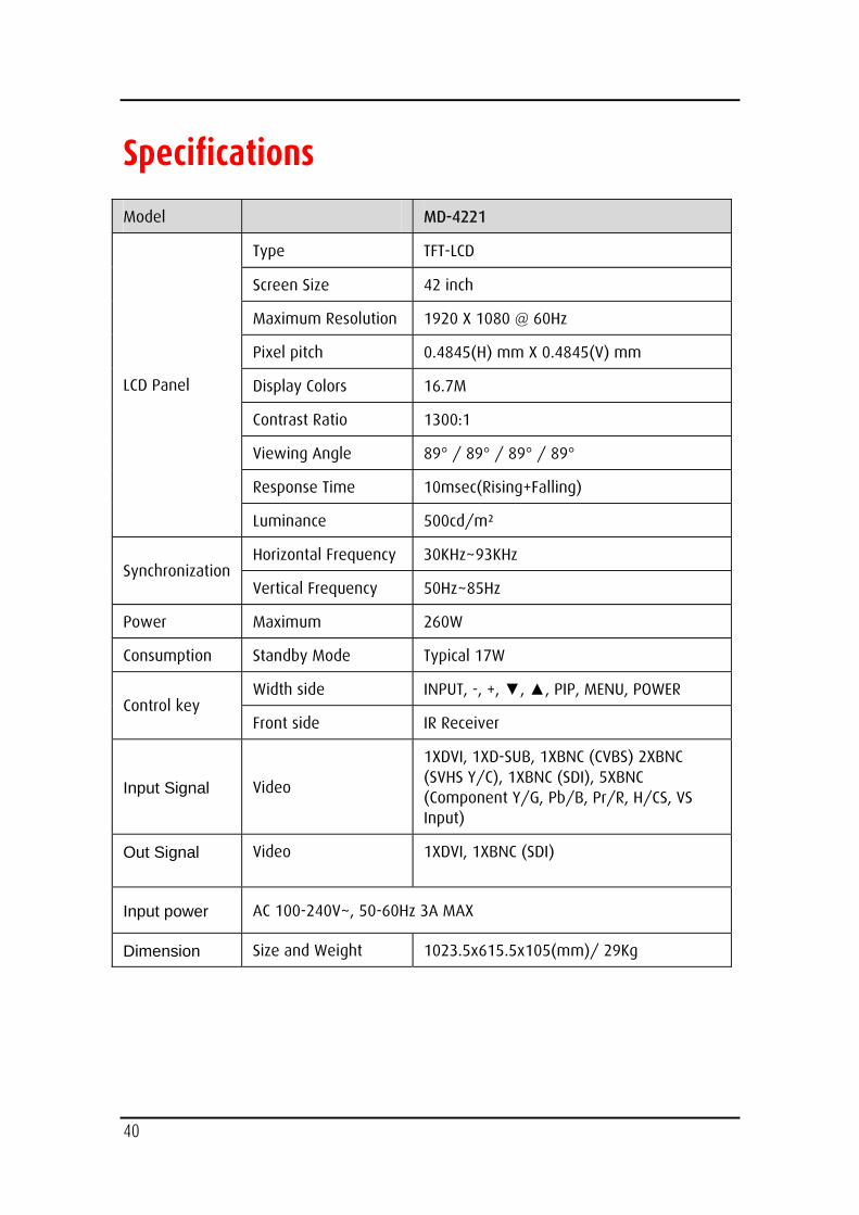
Specifications
Model MD-4221
Type TFT-LCD
Screen Size 42 inch
Maximum Resolution 1920 X 1080 @ 60Hz
Pixel pitch 0.4845(H) mm X 0.4845(V) mm
Display Colors 16.7M
Contrast Ratio 1300:1
Viewing Angle 89° / 89° / 89° / 89°
Response Time 10msec(Rising+Falling)
LCD Panel
Luminance 500cd/m²
Horizontal Frequency 30KHz~93KHz Synchronization
Vertical Frequency 50Hz~85Hz
Power Maximum 260W
Consumption Standby Mode Typical 17W
Width side INPUT, -, +, ▼, ▲, PIP, MENU, POWER Control key
Front side IR Receiver
Input Signal Video
1XDVI, 1XD-SUB, 1XBNC (CVBS) 2XBNC (SVHS Y/C), 1XBNC (SDI), 5XBNC (Component Y/G, Pb/B, Pr/R, H/CS, VS Input)
Out Signal Video 1XDVI, 1XBNC (SDI)
Input power AC 100-240V~, 50-60Hz 3A MAX
Dimension Size and Weight 1023.5x615.5x105(mm)/ 29Kg
41
BARCO MID GENERAL WARRANTY TERMS AND CONDITIONS Applicable from Jan 1st 2008
ARTICLE 1: PRODUCT WARRANTY Barco nv, Medical Imaging Division warrants that the equipment will be free of defects in workmanship or material for the warranty period or the specific period of a warranty extension program.
Hardware: Barco warrants that upon delivery hereunder the Products shall (i) conform to its specifications in effect at the date of delivery and (ii) be free from defects in material and workmanship (the "Warranties").
Software: Barco warrants that software written by Barco shall perform substantially in accordance with the specifications in effect at the date of delivery. Software is inherently susceptible to bugs and errors. Barco makes no warranties with respect to the software which is provided to Customer on an "as-is" basis and does not warrant uninterrupted or error-free operation of the Products.
Unless otherwise indicated in Barco’s web site or in the agreement between Barco and Customer, the Warranty Period shall be
(a) Hardware: 12 months commencing on the Barco date of invoice.
(b) Software: 3 months commencing on the Barco date of invoice.
Notwithstanding the provisions of clause 2, repair and replacement of defects in material and/or workmanship under this warranty shall be accomplished in our works according to the terms and conditions as set forth hereafter:
1.1
Any claim under the Warranties must be notified to Barco in writing within 8 days from the date the defect or failure has been discovered or noticed the first time. The Customer, upon the occurrence of any equipment failure, shall contact Barco nv, MID customer support centre (or an authorised service centre) by telephone, fax or e-mail and shall provide the applicable customer support person with a complete description of the problem being encountered, including the model and serial number of the equipment in which the problem has arisen.
1.2
The customer support person shall diagnose the problem experienced by the Customer and shall advise the Customer on how to proceed. Customer support may ask to return the faulty equipment or faulty subassemblies to the Barco nv, or a MID customer support centre (or an authorised service centre) for repair activities. In no event shall Customer return a defective Product or part thereof to Barco without Barco's prior written approval.
In the event the return to Barco of the defective Product is authorized by Barco, Barco shall issue to Customer an RMA (Return Material Authorization).
The Customer shall apply for an RMA number to the closest Barco nv, MID Customer support centre (or an authorised service centre) as listed at www.barcomedical.com, unless otherwise indicated.
The one-way cost of packing, transport and insurance related to shipping the alleged defective Product or part to Barco for repair or replacement shall be borne by Customer. The one-way cost of packing, transport and insurance related to shipping of the repaired or replacement Product or part to Customer shall be borne by Barco.
1.3
The Customer shall return, freight prepaid, the defective equipment or subassemblies in its original packaging with the assigned RMA number for repair to the Barco nv, MID Customer support centre (or
42
an authorised service centre).
1.4
Replacement parts used shall be new or equivalent to new parts for the revision level of the equipment. A replacement LCD panel will be new or similar run time. The warranty period for the replacement parts will expire at the same moment as the original warranty period of the equipment. All parts replaced hereunder and returned to Barco nv, MID (or an authorised service centre) shall become the property of Barco nv, MID (or the authorised service centre).
1.5
The repaired equipment shall be returned to the Customer, by regular freight, at Barco nv, MID’s charge.
1.6
Barco nv, MID will replace a product that fails within 90 days after shipment from Barco with a new one, ensuring color matching in the event of a diagnostic multi head display configuration.
Barco aims to ship the new replacement product within 2 business days after receipt of the Customers notification in writing.
ARTICLE 2: CONDITIONS PRECEDENT FOR WARRANTY AND ITEMS EXCLUDED FROM WARRANTY A. The Warranties shall apply only to the extent the Products or any parts thereof have
(i) been transported and stored at all times in the original packaging in the conditions as specified by Barco (such as covered and secure location, minimum and maximum temperature, maximum humidity, …) or, in absence thereof, at least in conditions consistent with generally accepted practice for this type of products;
(ii) been handled at all times in accordance with Barco's instructions or, in absence thereof, at least with the care and caution consistent with generally accepted practice for this type of products;
(iii) been installed strictly in accordance with the instructions and directions given by Barco (if and to the extent the Products have not been installed by Barco or its authorized subcontractors);
(iv) not been subject to any unauthorized access, alteration, modification or repair or attempts thereto;
(v) been at all times "normally used" for the intended purpose and operated in strict accordance with the operating instructions set forth in the operating manual of the Product in question and shall not have been otherwise misused, abused, damaged. For the purpose hereof, "normally used" shall mean a regular, ordinary and routine usage of the Product in question as intended and/or recommended by Barco;
(vi) been maintained at all times in accordance with Barco's instructions or, in absence thereof, at least with intervals and in a manner consistent with generally accepted practice for this type of products;
B. The warranty described herein shall not include the following:
2.1
Any hardware or software item procured from a source other than Barco nv, MID or their official agent or distributor and integrated by Customer or a third party into Barco nv, MID supplied equipment.
2.2
Any host configuration not explicitly supported by Barco nv, MID.
2.3
All software installed on the system, whether they are acquired from Barco nv, MID or third party. An exception is made for software delivered by Barco nv, MID that would prove to be a cause for the mal functioning of the hardware covered under this Agreement.
2.4
43
Normal wear and tear, use under circumstances exceeding specifications, such as use in dusty environment or under excessive temperature conditions, abuse, unauthorised repair or alternation, lack of proper configuration or maintenance, damaged or modified or removed serial number, cosmetic refurbishment.
2.5
Repair or replacement of consumables1 or specific parts that by definition are subject to wear and tear, including but not limited to:
a. CRT’s, LCD panels
b. Backlights in diagnostic LCD displays, when the backlight run time2 is beyond the Guaranteed Backlight Lifetime3 of that model, when used at the Factory Calibrated Luminance4
Eg1.
• A display is used at 8 hours/day; ie. +/-2.920hours/year
• The display system is covered with a warranty period of 5 year
• The Guaranteed Backlight Lifetime of that model is 17.000hours.
• The Factory Calibrated Luminance cannot be achieved anymore after 4 year, thus corresponding to +/-11.680hours
• Result: the backlight replacement is performed under warranty
Eg2.
• A display is used at 24 hours/day; ie. 8.760hours/year
• The display system is covered with a warranty program of 5 year
• The Guaranteed Backlight Lifetime of that model is 17.000hours.
• The Factory Calibrated Luminance cannot be achieved anymore after 2.5years, thus corresponding to +/-21.900hours
• Result: the backlight replacement does not make part of the warranty coverage.
(1): ‘Consumable’ is a part that can be replaced by the user
(2): ‘Backlight run time’ is the total time that an image (including use of a screen saver) has been applied to the screen; this value can be consulted via the OSD buttons (On Screen Display).
(3): ‘Guaranteed Backlight Lifetime’ is the number of backlight hours during which a predefined luminance value, ie. the Factory Calibrated Luminance, will be provided by a specific diagnostic display model. This figure is printed on the Warranty certificate of each display or can be requested at your local Barco office.
(4): ‘Factory Calibrated Luminance’: is the typical luminance value that a specific diagnostic display model is calibrated at during the production process. This figure is printed on the Warranty certificate of each display or can be requested at your local Barco office.
c. Lamps, optical components in projectors
d. Replacement because of:
i. image retention as a result of:
- not correctly using screen saver and/or Display Power Management System (DPMS) as explained in the user manual
- prolonged operation of the display with a static image on the same screen area
ii . a number of missing pixels that is lower than the total allowable number as mentioned in the product specifications.
iii. difference in color temperature that is lower than the total allowable difference as mentioned in the product specifications
iv. difference in color temperature as a result of not using all displays of a multi-head configuration at the same rate.
44
v. LCD luminance uniformity that is in within the product specifications or luminance uniformity performance that is inherent to LCD technology.
Barco nv, MID does not warrant a minimum life time nor a performance of any of the consumables.
2.6
Replacement of moveable parts such as power cords, remote controls, …
2.7
Any product disassembly and installation costs at the operation site, travel expenses and travel time to and from the operation site for the personnel in charge of the repair works and transport charges.
2.8
Any failures resulting from an accident, negligence (such as but not limited to removing or deleting system files & licensed software product files), misuse, circuit failure or any change, damage due to fire, water, thunder or lightning, power failure or fluctuation, disruption of communication lines or due to force majeure, or any reason foreign to the equipment.
2.9
Any specific services or procedures, asked for by Customer, related to verification of repaired equipment.
2.10 The evaluation cost in case of a returned product deemed functional is not covered under warranty and will be charged to the Customer, at Barco’s sole discretion, based on a case-by-case evaluation.
ARTICLE 3: OBLIGATIONS OF THE CUSTOMER Customer hereby assumes the following obligations as partial consideration for Barco nv, MID performance of its requirements under the warranty condition; failure by Customer to meet its obligations under this paragraph shall excuse Barco nv, MID’s performance hereunder:
3.1
Customer shall not expose Barco nv, MID personnel to any unsafe working conditions.
3.2
Repairs to equipment under warranty resulting from improper maintenance or repair performed by the Customer, or its officers, agents, employees, or representatives, shall be borne by the Customer at its additional cost and expense.
3.3
The Customer is responsible for installing the Barco nv, MID equipment in an environment for which it was intended. If there is an indication that the equipment was used – even temporary – outside its specifications, Barco nv, MID is entitled not to perform warranty repairs and terminate the warranty agreement. Any actions that have been taken by Barco nv, MID in this respect, may be invoiced to the Customer at normal pricing.
ARTICLE 4: REMEDIES UNDER WARRANTY (a) Hardware: If during the Warranty Period a Product or any part thereof, fails to meet any of the Warranties then, upon Customer's request, Barco shall, at its sole option and cost, promptly and within 20 working days, either: (i) repair or correct the Product or part in question; or (ii) replace the Product or supply part(s) or component(s) according to the terms and conditions contained in article 1. A replacement part shall be at least functionally equivalent to the original part. The replaced Product, parts and/or components shall become the property of Barco and shall, at Barco's request, be returned by Customer to Barco at Barco's cost.
(b) Software: Barco's sole obligation shall be to rectify substantial malfunctions of the software (to the extent technically reasonably possible) by amending the software or supplying an alternative version of the software.
(c) The repair or replacement under the Warranties covers the cost of material and labor.
45
ARTICLE 5: DISCLAIMER OF WARRANTIES BARCO NV, MID DISCLAIMS ALL WARRANTIES, EXPRESSED OR IMPLIED, INCLUDING ALL IMPLIED WARRANTIES OF MERCHANTABILITY AND FITNESS FOR A PARTICULAR PURPOSE.
ARTICLE 6: LIMITATION OF LIABILITY BARCO NV, MID SHALL NOT UNDER ANY CIRCUMSTANCES BE LIABLE TO CUSTOMER OR ANY THIRD PARTY FOR DIRECT, INDIRECT, INCIDENTAL, SPECIAL OR CONSEQUENTIAL DAMAGES, SUCH AS BUT NOT LIMITED TO, DAMAGE TO OR LOSS OF TANGIBLE OR INTANGIBLE PROPERTY OR EQUIPMENT, LOSS OF PROFITS OR REVENUES, COST OF CAPITAL, COST OF PURCHASE OF REPLACEMENT GOODS, OR CLAIMS OF CUSTOMERS OF USER FOR SERVICE INTERRUPTIONS. THE LIABILITY OF BARCO NV, MID FOR MANUFACTURING, SALE, DELIVERY, RESALE, INSTALLATION, OPERATION OR SUITABILITY FOR USE OF ANY PRODUCTS OR SERVICES COVERED BY OR FURNISHED UNDER THIS WARRANTY CONDITION, WHETHER ARISING OUT OF CONTRACT, NEGLIGENCE, STRICT TORT, WARRANTY OR OTHERWISE, SHALL BE LIMITED TO THE REPAIR OR REPLACEMENT OF THE PRODUCT OR ANY PART THEREOF WHICH SHALL BE AT CUSTOMER'S SOLE OPTION AND COST. BARCO’S LIABILITY SHALL NOT EXCEED THE PRICE OF THE ITEM OR ITEMS OF GOODS OR SERVICES UPON WHICH SUCH LIABILITY IS BASED.
ARTICLE 7: FORCE MAJEURE Either party shall be released from performance of its obligations under this agreement to the extent, and for so long as, the performance of this agreement is impeded by reason of force majeure. For the purposes of this clause the expression "force majeure" means, but shall not be limited to, industrial dispute, fire, mobilisation, requisition, embargo, currency transfer prohibitions, insurrection, lack of means of transport, restrictions of the use of energy, and generally any circumstances which are beyond the control of the parties and hinder performance by one party of his obligations.
ARTICLE 8: GENERAL 8.1
Customer acknowledges its understanding that all software and electronic devices, including Barco nv, MID products are subject to possible error, mechanical or electrical failure, and should not be relied upon in inappropriate applications or without proper backup and/or other safety precautions whenever personal injury or property damage may result from failure or error of the product.
8.2
Barco nv, MID shall not be responsible for machine failure and/or its failure to render service or maintenance due to causes beyond its reasonable control.

46

B410615-01
August 2009
Barco N.V.
President Kennedypark 35
B-8500 Kortrijk, Belgium
visit us at the web: www.barco.com
Support helpdesk:
Asia Pacific: +886-2-8221-6868 ext. 699
Europe, Middle East and Africa: +32 56 233 376
Japan: +81 3 3279 0771
Americas: +1 (678) 475-8262