Embed Size (px)
Citation preview
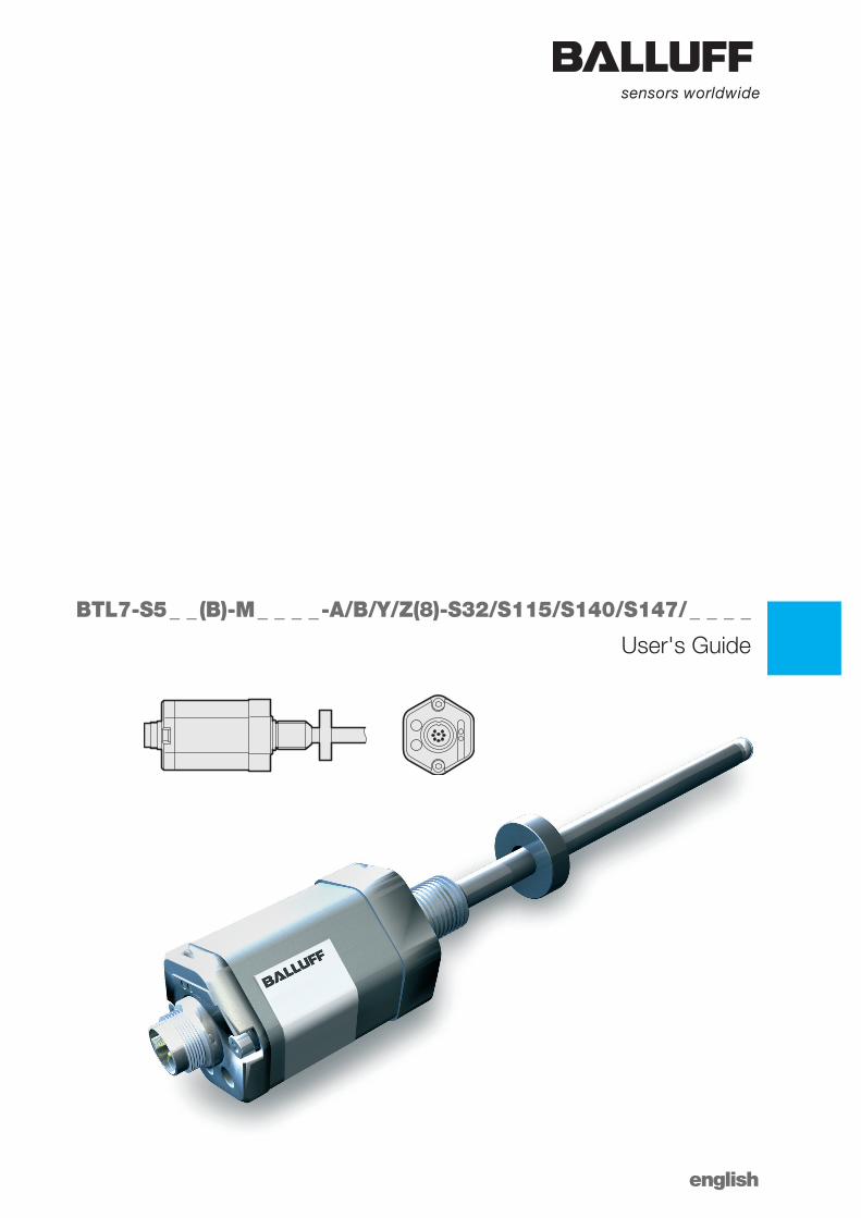
User's Guide
english
BTL7-S5 _ _ (B)-M _ _ _ _ -A/B/Y/Z(8)-S32/S115/S140/S147/ _ _ _ _

www.balluff.com
www.balluff.com 3english
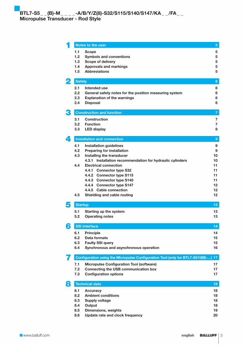
BTL7-S5 _ _ (B)-M _ _ _ _ -A/B/Y/Z(8)-S32/S115/S140/S147/KA _ _ /FA _ _Micropulse Transducer - Rod Style
1 Notes to the user 5
1.1 Scope 51.2 Symbols and conventions 51.3 Scope of delivery 51.4 Approvals and markings 51.5 Abbreviations 5
2 Safety 6
2.1 Intended use 62.2 General safety notes for the position measuring system 62.3 Explanation of the warnings 62.4 Disposal 6
3 Construction and function 7
3.1 Construction 73.2 Function 73.3 LED display 8
4 Installation and connection 9
4.1 Installation guidelines 94.2 Preparing for installation 94.3 Installing the transducer 10
4.3.1 Installation recommendation for hydraulic cylinders 104.4 Electrical connection 11
4.4.1 Connector type S32 114.4.2 Connector type S115 114.4.3 Connector type S140 114.4.4 Connector type S147 124.4.5 Cable connection 12
4.5 Shielding and cable routing 12
5 Startup 13
5.1 Starting up the system 135.2 Operating notes 13
6 SSI interface 14
6.1 Principle 146.2 Data formats 156.3 Faulty SSI query 156.4 Synchronous and asynchronous operation 16
7 Configuration using the Micropulse Configuration Tool (only for BTL7-S510(B)-…) 17
7.1 Micropulse Configuration Tool (software) 177.2 Connecting the USB communication box 177.3 Configuration options 17
8 Technical data 18
8.1 Accuracy 188.2 Ambient conditions 188.3 Supply voltage 188.4 Output 188.5 Dimensions, weights 198.6 Update rate and clock frequency 20
4 english
BTL7-S5 _ _ (B)-M _ _ _ _ -A/B/Y/Z(8)-S32/S115/S140/S147/KA _ _ /FA _ _Micropulse Transducer - Rod Style
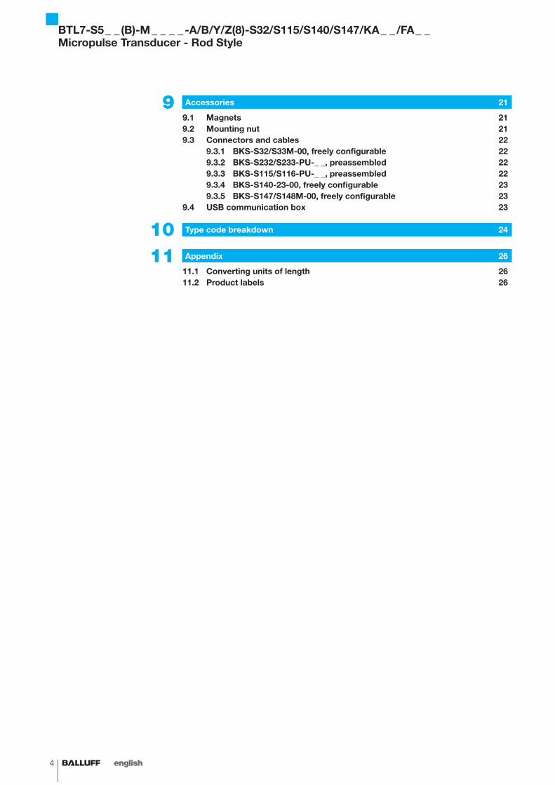
9 Accessories 21
9.1 Magnets 219.2 Mounting nut 219.3 Connectors and cables 22
9.3.1 BKS-S32/S33M-00, freely configurable 229.3.2 BKS-S232/S233-PU-_ _, preassembled 229.3.3 BKS-S115/S116-PU-_ _, preassembled 229.3.4 BKS-S140-23-00, freely configurable 239.3.5 BKS-S147/S148M-00, freely configurable 23
9.4 USB communication box 23
10 Type code breakdown 24
11 Appendix 26
11.1 Converting units of length 2611.2 Product labels 26
www.balluff.com 5english
1.1 Scope
This guide describes the construction, function and setup options for the BTL7 Micropulse Transducer with SSI interface. It applies to types BTL7-S5 _ _ (B)-M _ _ _ _ -A/B/Y/Z(8)-S32/S115/S140/S147/KA _ _ /FA _ _ (see Type code breakdown on page 24 or page 25).
The guide is intended for qualified technical personnel. Read this guide before installing and operating the transducer.
1.2 Symbols and conventions
Individual instructions are indicated by a preceding triangle.
► Instruction 1
Action sequences are numbered consecutively:1. Instruction 12. Instruction 2
Note, tipThis symbol indicates general notes.
1.3 Scope of delivery
– BTL7 transducer– Condensed guide
The magnets are available in various models and must be ordered separately.
1.4 Approvals and markings
UL approval1)
File no.E227256
US Patent 5 923 164The US patent was awarded in connection with this product.
1) Not for BTL7-…-FA_ _
The CE Mark verifies that our products meet the requirements of the current EMC Directive.
The transducer meets the requirements of the following product standard:– EN 61326-2-3 (noise immunity and emission)
Emission tests:
– RF emission EN 55011
Noise immunity tests:
– Static electricity (ESD) EN 61000-4-2 Severity level 3
– Electromagnetic fields (RFI) EN 61000-4-3 Severity level 3
– Electrical fast transients (burst) EN 61000-4-4 Severity level 3
– Surge EN 61000-4-5 Severity level 2
– Conducted interference induced by high-frequency fields EN 61000-4-6 Severity level 3
– Magnetic fields EN 61000-4-8 Severity level 4
More detailed information on the guidelines, approvals, and standards is included in the declaration of conformity.
1.5 Abbreviations
SSI Synchronous Serial Interface
1 Notes to the user
BTL7-S5 _ _ (B)-M _ _ _ _ -A/B/Y/Z(8)-S32/S115/S140/S147/KA _ _ /FA _ _Micropulse Transducer - Rod Style
6 english
2.1 Intended use
The Micropulse Transducer, together with a machine controller (e.g. PLC), comprises a position measuring system. It is intended to be installed into a machine or system. Flawless function in accordance with the specifications in the technical data is ensured only when using original BALLUFF accessories. Use of any other components will void the warranty.
Opening the transducer or non-approved use are not permitted and will result in the loss of warranty and liability claims against the manufacturer.
2.2 General safety notes for the position measuring system
Installation and startup may only be performed by trained specialists with basic electrical knowledge.
Qualified personnel are those who can recognize possible hazards and institute the appropriate safety measures due to their professional training, knowledge, and experience, as well as their understanding of the relevant regulations pertaining to the work to be done.
The operator is responsible for ensuring that local safety regulations are observed.In particular, the operator must take steps to ensure that a defect in the position measuring system will not result in hazards to persons or equipment.If defects and unresolvable faults occur in the transducer, it should be taken out of service and secured against unauthorized use.
2.3 Explanation of the warnings
Always observe the warnings in these instructions and the measures described to avoid hazards.
The warnings used here contain various signal words and are structured as follows:
SIGNAL WORDHazard type and sourceConsequences if not complied with
► Measures to avoid hazards
The individual signal words mean:
NOTICE!Identifies a hazard that could damage or destroy the product.
DANGERThe general warning symbol in conjunction with the signal word DANGER identifies a hazard which, if not avoided, will certainly result in death or serious injury.
2.4 Disposal
► Observe the national regulations for disposal.
2 Safety
BTL7-S5 _ _ (B)-M _ _ _ _ -A/B/Y/Z(8)-S32/S115/S140/S147/KA _ _ /FA _ _Micropulse Transducer - Rod Style
www.balluff.com 7english
Fig. 3-1:
Ø 6.7
0.5 Ø 257111 25
60
Ø D
1 G
45
4613.512.8
71 (74.5) 25
74.512.8
BTL7…cable
BTL7…S115 BTL7…S32/S147
1)
1) 2)
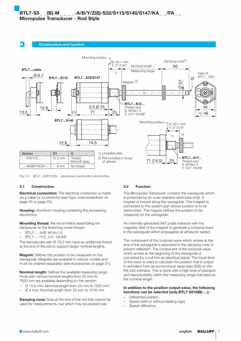
BTL7…A/B/Y/Z(8)… transducer, construction and function
3.1 Construction
Electrical connection: The electrical connection is made via a cable or a connector (see Type code breakdown on page 24 or page 25).
Housing: Aluminum housing containing the processing electronics.
Mounting thread: We recommend assembling the transducer on the fastening screw thread:– BTL7-…-A/B: M18×1.5– BTL7-…-Y/Z: 3/4”-16UNFThe transducers with Ø 10.2 mm have an additional thread at the end of the rod to support larger nominal lengths.
Magnet: Defines the position to be measured on the waveguide. Magnets are available in various models and must be ordered separately (see Accessories on page 21).
Nominal length: Defines the available measuring range. Rods with various nominal lengths from 25 mm to 7620 mm are available depending on the version:– Ø 10.2 mm: Nominal length from 25 mm to 7620 mm– Ø 8 mm: Nominal length from 25 mm to 1016 mm
Damping zone: Area at the end of the rod that cannot be used for measurements, but which may be passed over.
3.2 Function
The Micropulse Transducer contains the waveguide which is protected by an outer stainless steel tube (rod). A magnet is moved along the waveguide. This magnet is connected to the system part whose position is to be determined. The magnet defines the position to be measured on the waveguide.
An internally generated INIT pulse interacts with the magnetic field of the magnet to generate a torsional wave in the waveguide which propagates at ultrasonic speed.
The component of the torsional wave which arrives at the end of the waveguide is absorbed in the damping zone to prevent reflection. The component of the torsional wave which arrives at the beginning of the waveguide is converted by a coil into an electrical signal. The travel time of the wave is used to calculate the position that is output in antivalent form as synchronous serial data (SSI) on the RS-422 interface. This is done with a high level of precision and reproducibility within the measuring range indicated as the nominal length.
In addition to the position output value, the following functions can be selected (only BTL7-S510(B)-…):– Differential position– Speed (with or without leading sign)– Speed difference
3 Construction and function
Nominal length =
Measuring range
Mounting surfaceB: 30-1 mmZ: 2"-0.04"
Damping zone1)
Magnet 2)
BTL7…B/Z…Thread size:B: M18x1.5Z: 3/4"-16UNF
Mounting surfaceA: 30-1 mmY: 2"-0.04"
BTL7…A/Y…Thread size:A: M18x1.5Y: 3/4"-16UNF
1) Unusable area
2) Not included in scope of delivery
Version D1 G…-A/B/Y/Z-… 10.2 mm Thread
M4x4/6 deep…-A8/B8/Y8/Z8-… 8 mm No thread
BTL7…S140
View of BTL7…S32
BTL7-S5 _ _ (B)-M _ _ _ _ -A/B/Y/Z(8)-S32/S115/S140/S147/KA _ _ /FA _ _Micropulse Transducer - Rod Style
8 english
3 Construction and function (continued)
3.3 LED display
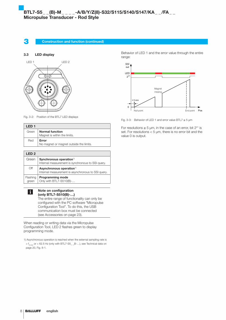
Fig. 3-2:
LED 1 LED 2
Position of the BTL7 LED displays
LED 1
Green Normal functionMagnet is within the limits.
Red ErrorNo magnet or magnet outside the limits.
LED 2
Green Synchronous operation1)
Internal measurement is synchronous to SSI query.
Off Asynchronous operation1)
Internal measurement is asynchronous to SSI query.
Flashing green
Programming modeOnly with BTL7-S510(B)-…
Note on configuration (only BTL7-S510(B)-…)The entire range of functionality can only be configured with the PC software "Micropulse Configuration Tool". To do this, the USB communication box must be connected (see Accessories on page 23).
When reading or writing data via the Micropulse Configuration Tool, LED 2 flashes green to display programming mode.
1) Asynchronous operation is reached when the external sampling rate is
> fA,max or < 62.5 Hz (only with BTL7-S5_ _B-…), see Technical data on
page 20, Fig. 8-1.
Behavior of LED 1 and the error value through the entire range:
Fig. 3-3:
Pos
SSI out
0
≈ 5 mm
221LED
Behavior of LED 1 and error value BTL7 ≥ 5 µm
For resolutions ≥ 5 µm, in the case of an error, bit 221 is set. For resolutions < 5 µm, there is no error bit and the value 0 is output.
Null point End point
Magnet missing
BTL7-S5 _ _ (B)-M _ _ _ _ -A/B/Y/Z(8)-S32/S115/S140/S147/KA _ _ /FA _ _Micropulse Transducer - Rod Style
www.balluff.com 9english
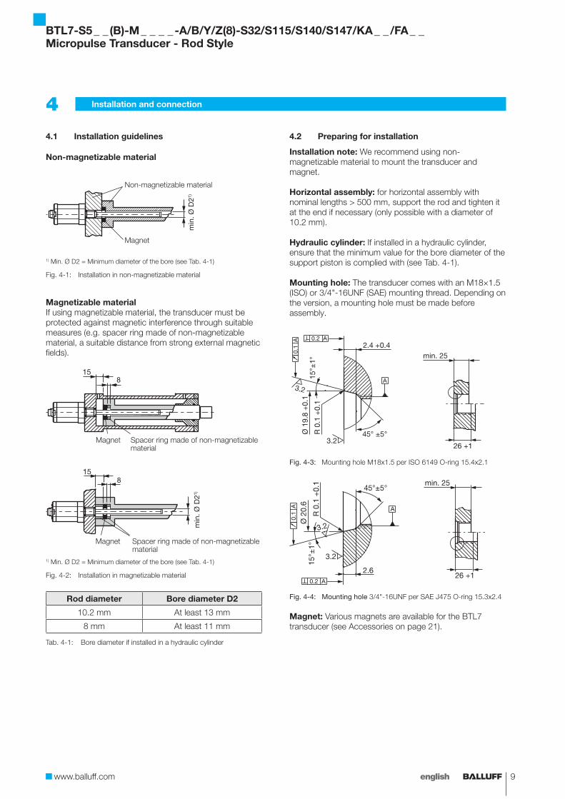
4.1 Installation guidelines
Non-magnetizable material
min
.Ø D
21)
Magnet
Non-magnetizable material
1) Min. Ø D2 = Minimum diameter of the bore (see Tab. 4-1)
Fig. 4-1: Installation in non-magnetizable material
Magnetizable materialIf using magnetizable material, the transducer must be protected against magnetic interference through suitable measures (e.g. spacer ring made of non-magnetizable material, a suitable distance from strong external magnetic fields).
Spacer ring made of non-magnetizable material
Magnet
min
.Ø D
21)
Spacer ring made of non-magnetizable material
Magnet
1) Min. Ø D2 = Minimum diameter of the bore (see Tab. 4-1)
Fig. 4-2: Installation in magnetizable material
Rod diameter Bore diameter D2
10.2 mm At least 13 mm
8 mm At least 11 mm
Tab. 4-1: Bore diameter if installed in a hydraulic cylinder
4.2 Preparing for installation
Installation note: We recommend using non-magnetizable material to mount the transducer and magnet.
Horizontal assembly: for horizontal assembly with nominal lengths > 500 mm, support the rod and tighten it at the end if necessary (only possible with a diameter of 10.2 mm).
Hydraulic cylinder: If installed in a hydraulic cylinder, ensure that the minimum value for the bore diameter of the support piston is complied with (see Tab. 4-1).
Mounting hole: The transducer comes with an M18×1.5 (ISO) or 3/4"-16UNF (SAE) mounting thread. Depending on the version, a mounting hole must be made before assembly.
Fig. 4-3: Mounting hole M18x1.5 per ISO 6149 O-ring 15.4x2.1
Fig. 4-4: Mounting hole 3/4"-16UNF per SAE J475 O-ring 15.3x2.4
Magnet: Various magnets are available for the BTL7 transducer (see Accessories on page 21).
4 Installation and connection
BTL7-S5 _ _ (B)-M _ _ _ _ -A/B/Y/Z(8)-S32/S115/S140/S147/KA _ _ /FA _ _Micropulse Transducer - Rod Style
10 english
4.3 Installing the transducer
NOTICE!Interference in functionImproper installation can compromise the function of the transducer and result in increased wear.
► The mounting surface of the transducer must make full contact with the supporting surface.
► The bore must be perfectly sealed (O-ring/flat seal).
► Make a mounting hole with thread (possibly with countersink for the O-ring) acc. to Fig. 4-3 or Fig. 4-4.
► Screw the transducer with mounting thread into the mounting hole (max. torque 100 Nm).
► Install the magnet (accessories). ► From 500 mm nominal length: support the rod and
tighten it at the end if necessary (only possible with a diameter of 10.2 mm).
Suitable nuts for the mounting thread are available as accessories (see page 21).
4.3.1 Installation recommendation for hydraulic cylinders
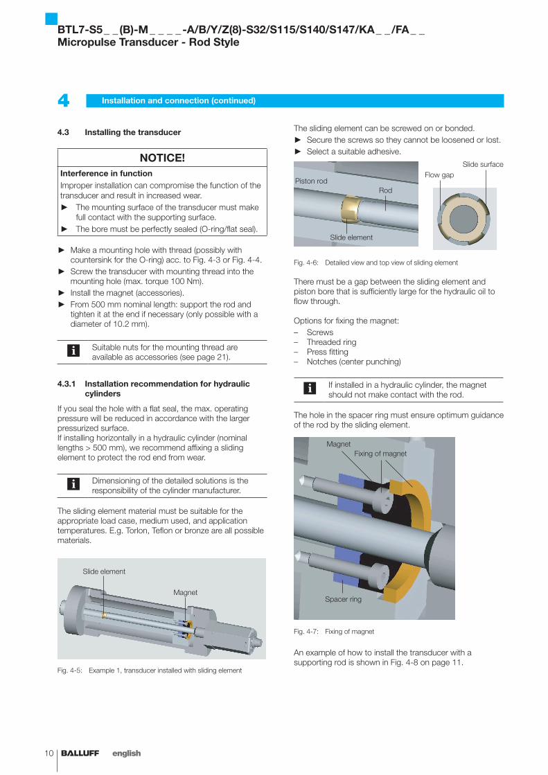
If you seal the hole with a flat seal, the max. operating pressure will be reduced in accordance with the larger pressurized surface.If installing horizontally in a hydraulic cylinder (nominal lengths > 500 mm), we recommend affixing a sliding element to protect the rod end from wear.
Dimensioning of the detailed solutions is the responsibility of the cylinder manufacturer.
The sliding element material must be suitable for the appropriate load case, medium used, and application temperatures. E.g. Torlon, Teflon or bronze are all possible materials.
Fig. 4-5: Example 1, transducer installed with sliding element
The sliding element can be screwed on or bonded. ► Secure the screws so they cannot be loosened or lost. ► Select a suitable adhesive.
Fig. 4-6: Detailed view and top view of sliding element
There must be a gap between the sliding element and piston bore that is sufficiently large for the hydraulic oil to flow through.
Options for fixing the magnet:– Screws– Threaded ring– Press fitting– Notches (center punching)
If installed in a hydraulic cylinder, the magnet should not make contact with the rod.
The hole in the spacer ring must ensure optimum guidance of the rod by the sliding element.
Fig. 4-7: Fixing of magnet
An example of how to install the transducer with a supporting rod is shown in Fig. 4-8 on page 11.
4 Installation and connection (continued)
Slide element
Magnet
Piston rodRod
Slide element
Flow gapSlide surface
MagnetFixing of magnet
Spacer ring
BTL7-S5 _ _ (B)-M _ _ _ _ -A/B/Y/Z(8)-S32/S115/S140/S147/KA _ _ /FA _ _Micropulse Transducer - Rod Style
www.balluff.com 11english
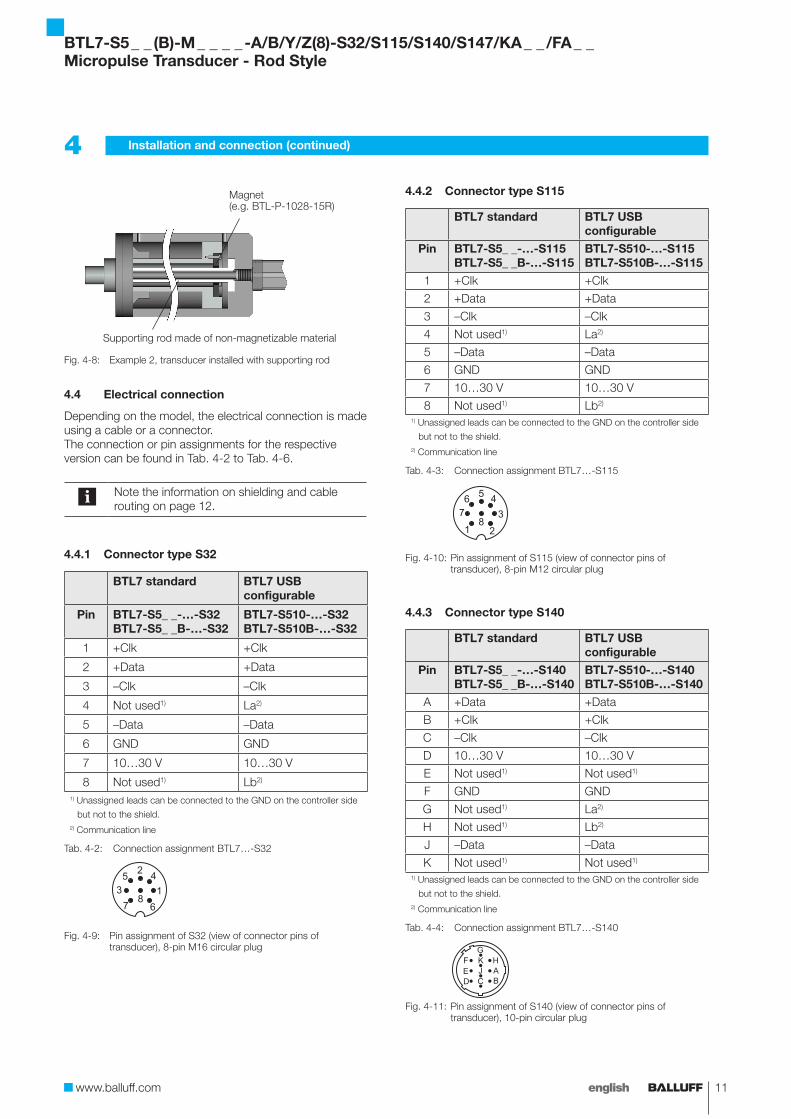
Fig. 4-8: Example 2, transducer installed with supporting rod
4.4 Electrical connection
Depending on the model, the electrical connection is made using a cable or a connector.The connection or pin assignments for the respective version can be found in Tab. 4-2 to Tab. 4-6.
Note the information on shielding and cable routing on page 12.
4.4.1 Connector type S32
BTL7 standard BTL7 USB configurable
Pin BTL7-S5_ _-…-S32BTL7-S5_ _B-…-S32
BTL7-S510-…-S32BTL7-S510B-…-S32
1 +Clk +Clk
2 +Data +Data
3 –Clk –Clk
4 Not used1) La2)
5 –Data –Data
6 GND GND
7 10…30 V 10…30 V
8 Not used1) Lb2)
1) Unassigned leads can be connected to the GND on the controller side
but not to the shield.2) Communication line
Tab. 4-2: Connection assignment BTL7…-S32
Fig. 4-9: Pin assignment of S32 (view of connector pins of transducer), 8-pin M16 circular plug
4.4.2 Connector type S115
BTL7 standard BTL7 USB configurable
Pin BTL7-S5_ _-…-S115BTL7-S5_ _B-…-S115
BTL7-S510-…-S115BTL7-S510B-…-S115
1 +Clk +Clk
2 +Data +Data
3 –Clk –Clk
4 Not used1) La2)
5 –Data –Data
6 GND GND
7 10…30 V 10…30 V
8 Not used1) Lb2)
1) Unassigned leads can be connected to the GND on the controller side
but not to the shield.2) Communication line
Tab. 4-3: Connection assignment BTL7…-S115
Fig. 4-10: Pin assignment of S115 (view of connector pins of transducer), 8-pin M12 circular plug
4.4.3 Connector type S140
BTL7 standard BTL7 USB configurable
Pin BTL7-S5_ _-…-S140BTL7-S5_ _B-…-S140
BTL7-S510-…-S140BTL7-S510B-…-S140
A +Data +Data
B +Clk +Clk
C –Clk –Clk
D 10…30 V 10…30 V
E Not used1) Not used1)
F GND GND
G Not used1) La2)
H Not used1) Lb2)
J –Data –Data
K Not used1) Not used1)
1) Unassigned leads can be connected to the GND on the controller side
but not to the shield.2) Communication line
Tab. 4-4: Connection assignment BTL7…-S140
Fig. 4-11:
ABC
JKG
HF
DE
Pin assignment of S140 (view of connector pins of transducer), 10-pin circular plug
4 Installation and connection (continued)
Magnet(e.g. BTL-P-1028-15R)
Supporting rod made of non-magnetizable material
BTL7-S5 _ _ (B)-M _ _ _ _ -A/B/Y/Z(8)-S32/S115/S140/S147/KA _ _ /FA _ _Micropulse Transducer - Rod Style
12 english
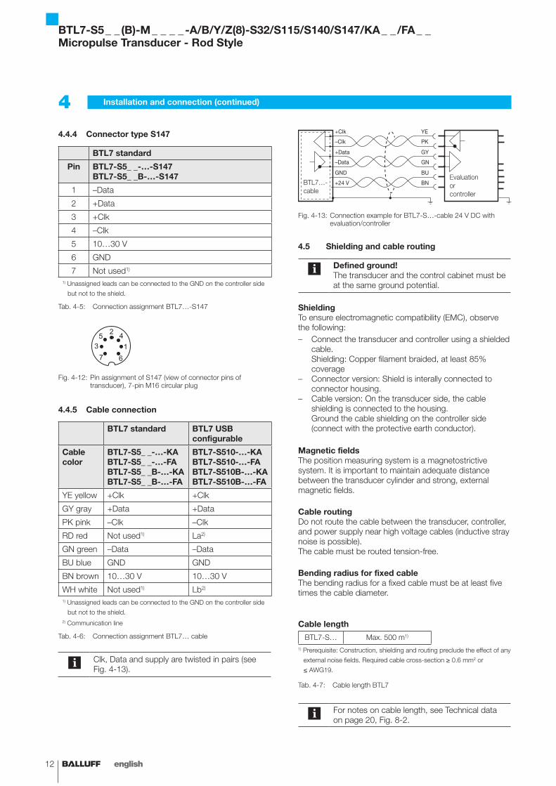
4.4.4 Connector type S147
BTL7 standard
Pin BTL7-S5_ _-…-S147BTL7-S5_ _B-…-S147
1 –Data
2 +Data
3 +Clk
4 –Clk
5 10…30 V
6 GND
7 Not used1)
1) Unassigned leads can be connected to the GND on the controller side
but not to the shield.
Tab. 4-5: Connection assignment BTL7…-S147
Fig. 4-12: Pin assignment of S147 (view of connector pins of transducer), 7-pin M16 circular plug
4.4.5 Cable connection
BTL7 standard BTL7 USB configurable
Cable color
BTL7-S5_ _-…-KABTL7-S5_ _-…-FA BTL7-S5_ _B-…-KABTL7-S5_ _B-…-FA
BTL7-S510-…-KABTL7-S510-…-FA BTL7-S510B-…-KABTL7-S510B-…-FA
YE yellow +Clk +Clk
GY gray +Data +Data
PK pink –Clk –Clk
RD red Not used1) La2)
GN green –Data –Data
BU blue GND GND
BN brown 10…30 V 10…30 V
WH white Not used1) Lb2)
1) Unassigned leads can be connected to the GND on the controller side
but not to the shield.2) Communication line
Tab. 4-6: Connection assignment BTL7… cable
Clk, Data and supply are twisted in pairs (see Fig. 4-13).
Fig. 4-13:
+Clk
–Clk
+Data
–Data
GND
+24 V
YE
PK
GY
GN
BU
BNEvaluationorcontroller
Connection example for BTL7-S…-cable 24 V DC with evaluation/controller
4.5 Shielding and cable routing
Defined ground!The transducer and the control cabinet must be at the same ground potential.
ShieldingTo ensure electromagnetic compatibility (EMC), observe the following:– Connect the transducer and controller using a shielded
cable. Shielding: Copper filament braided, at least 85% coverage
– Connector version: Shield is interally connected to connector housing.
– Cable version: On the transducer side, the cable shielding is connected to the housing. Ground the cable shielding on the controller side (connect with the protective earth conductor).
Magnetic fieldsThe position measuring system is a magnetostrictive system. It is important to maintain adequate distance between the transducer cylinder and strong, external magnetic fields.
Cable routingDo not route the cable between the transducer, controller, and power supply near high voltage cables (inductive stray noise is possible).The cable must be routed tension-free.
Bending radius for fixed cableThe bending radius for a fixed cable must be at least five times the cable diameter.
Cable length
BTL7-S… Max. 500 m1)
1) Prerequisite: Construction, shielding and routing preclude the effect of any
external noise fields. Required cable cross-section ≥ 0.6 mm2 or
≤ AWG19.
Tab. 4-7: Cable length BTL7
For notes on cable length, see Technical data on page 20, Fig. 8-2.
4 Installation and connection (continued)
BTL7…- cable
BTL7-S5 _ _ (B)-M _ _ _ _ -A/B/Y/Z(8)-S32/S115/S140/S147/KA _ _ /FA _ _Micropulse Transducer - Rod Style
www.balluff.com 13english
5 Startup
5.1 Starting up the system
DANGERUncontrolled system movementWhen starting up, if the position measuring system is part of a closed loop system whose parameters have not yet been set, the system may perform uncontrolled movements. This could result in personal injury and equipment damage.
► Persons must keep away from the system's hazardous zones.
► Startup must be performed only by trained technical personnel.
► Observe the safety instructions of the equipment or system manufacturer.
1. Check connections for tightness and correct polarity. Replace damaged connections.
2. Turn on the system.3. Check measured values and adjustable parameters
and readjust the transducer, if necessary.
Check for the correct values at the null point and end point, especially after replacing the transducer or after repair by the manufacturer.
5.2 Operating notes
– Check the function of the transducer and all associated components on a regular basis.
– Take the position measuring system out of operation whenever there is a malfunction.
– Secure the system against unauthorized use.
BTL7-S5 _ _ (B)-M _ _ _ _ -A/B/Y/Z(8)-S32/S115/S140/S147/KA _ _ /FA _ _Micropulse Transducer - Rod Style
14 english
6 SSI interface
6.1 Principle
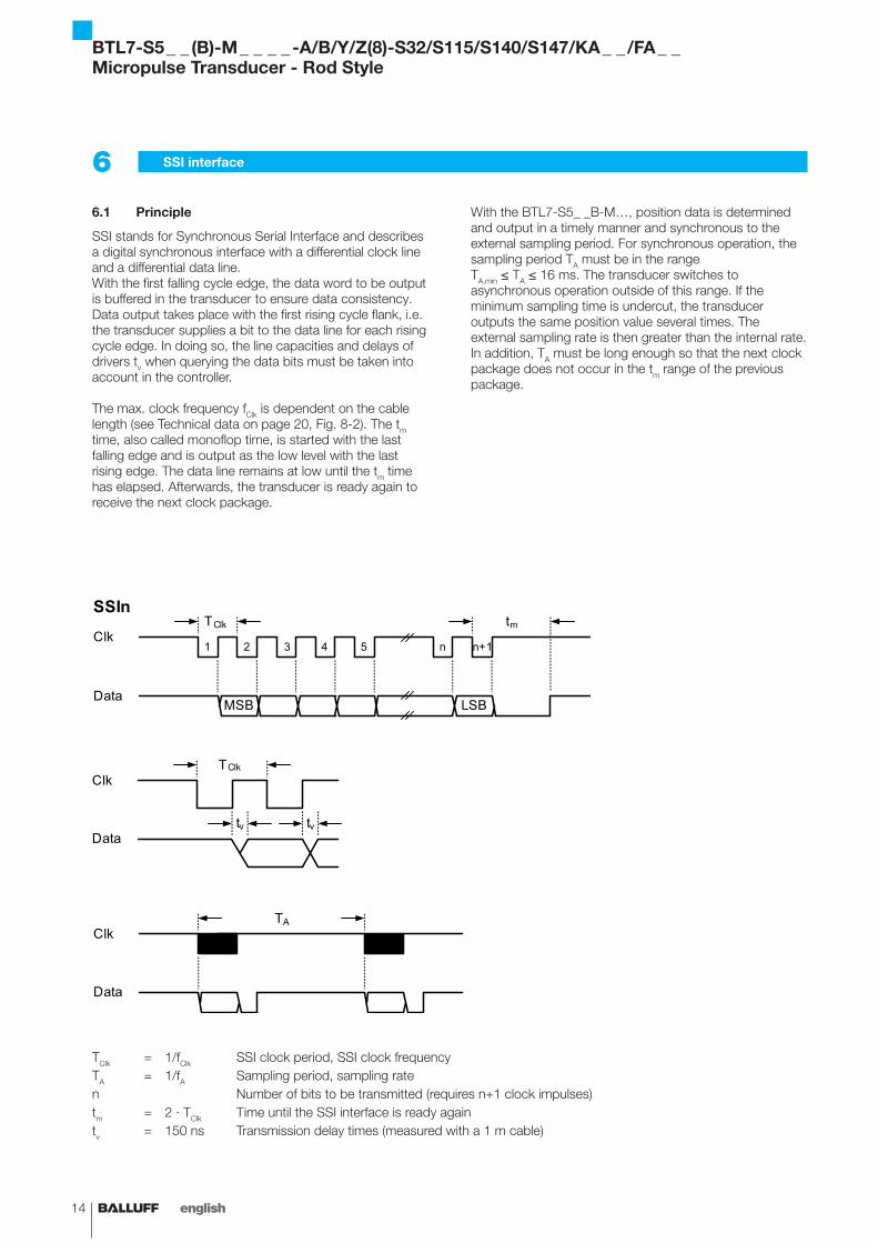
SSI stands for Synchronous Serial Interface and describes a digital synchronous interface with a differential clock line and a differential data line.With the first falling cycle edge, the data word to be output is buffered in the transducer to ensure data consistency. Data output takes place with the first rising cycle flank, i.e. the transducer supplies a bit to the data line for each rising cycle edge. In doing so, the line capacities and delays of drivers tv when querying the data bits must be taken into account in the controller.
The max. clock frequency fClk is dependent on the cable length (see Technical data on page 20, Fig. 8-2). The tm time, also called monoflop time, is started with the last falling edge and is output as the low level with the last rising edge. The data line remains at low until the tm time has elapsed. Afterwards, the transducer is ready again to receive the next clock package.
Clk
Data
TClk
tv tv
Clk
DataMSB LSB
TClk
1 2 3 4 5 n n+1
tmSSIn
Clk
Data
TA
TClk = 1/fClk SSI clock period, SSI clock frequencyTA = 1/fA Sampling period, sampling raten Number of bits to be transmitted (requires n+1 clock impulses)tm = 2 · TClk Time until the SSI interface is ready againtv = 150 ns Transmission delay times (measured with a 1 m cable)
With the BTL7-S5_ _B-M…, position data is determined and output in a timely manner and synchronous to the external sampling period. For synchronous operation, the sampling period TA must be in the range TA,min ≤ TA ≤ 16 ms. The transducer switches to asynchronous operation outside of this range. If the minimum sampling time is undercut, the transducer outputs the same position value several times. The external sampling rate is then greater than the internal rate. In addition, TA must be long enough so that the next clock package does not occur in the tm range of the previous package.
BTL7-S5 _ _ (B)-M _ _ _ _ -A/B/Y/Z(8)-S32/S115/S140/S147/KA _ _ /FA _ _Micropulse Transducer - Rod Style
www.balluff.com 15english
6 SSI interface (continued)
6.2 Data formats
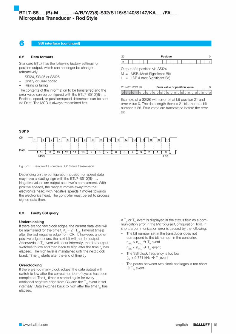
Standard BTL7 has the following factory settings for position output, which can no longer be changed retroactively:– SSI24, SSI25 or SSI26– Binary or Gray coded– Rising or fallingThe contents of the information to be transferred and the error value can be configured with the BTL7-S510(B)-…. Position, speed, or position/speed differences can be sent via Data. The MSB is always transmitted first.
23 Position 0
M L
Output of a position via SSI24M = MSB (Most Significant Bit)L = LSB (Least Significant Bit)
25 24 23 22 21 20 Error value or position value 0
0 0 0 0 1 0 0 0 0 0 0 0 0 0 0 0 0 0 0 0 0 0 0 0 0 0
Example of a SSI26 with error bit at bit position 21 and error value 0. The data length there is 21 bit, the total bit number is 26. Four zeros are transmitted before the error bit.
Clk
Data15
1 2 3 4 5
SSI16
14 13 12
6 7 8 9 10 11 12 13 14 15 16 17
11 10 9 8 7 6 5 4 3 2 1 0MSB LSB
Fig. 6-1: Example of a complete SSI16 data transmission
Depending on the configuration, position or speed data may have a leading sign with the BTL7-S510(B)-…. Negative values are output as a two's complement. With positive speeds, the magnet moves away from the electronics head; with negative speeds it moves towards the electronics head. The controller must be set to process signed data then.
6.3 Faulty SSI query
UnderclockingIf there are too few clock edges, the current data level will be maintained for the time to (to = 2 · TClk Timeout times) after the last negative edge from Clk. If, however, another positive edge occurs, the next bit will then be output. Afterwards, a To event will occur internally, the data output switches to low and then back to high after the time tm has elapsed. The high level is maintained until the next clock burst. Time tm starts after the end of time to.
OverclockingIf there are too many clock edges, the data output will switch to low after the correct number of cycles has been completed. The tm timer is started again for every additional negative edge from Clk and the Tm event is set internally. Data switches back to high after the time tm has elapsed.
A To or Tm event is displayed in the status field as a com-munication error in the Micropulse Configuration Tool. In short, a communication error is caused by the following:– The bit number set in the transducer does not
correspond to the bit number in the controller.nBTL > nPLC To event
nBTL < nPLC Tm event
– The SSI clock frequency is too lowfClk < 9.771 kHz To event
– The pause between two clock packages is too short Tm event
BTL7-S5 _ _ (B)-M _ _ _ _ -A/B/Y/Z(8)-S32/S115/S140/S147/KA _ _ /FA _ _Micropulse Transducer - Rod Style
16 english
6 SSI interface (continued)
6.4 Synchronous and asynchronous operation
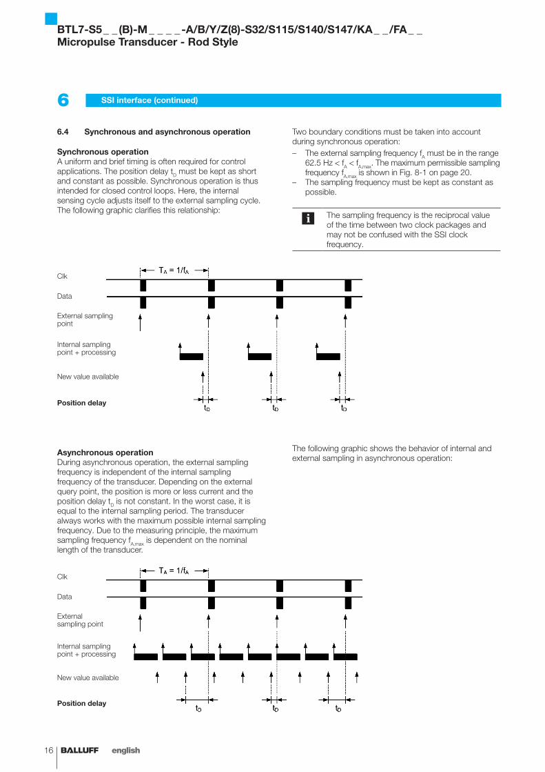
Synchronous operationA uniform and brief timing is often required for control applications. The position delay tD must be kept as short and constant as possible. Synchronous operation is thus intended for closed control loops. Here, the internal sensing cycle adjusts itself to the external sampling cycle.The following graphic clarifies this relationship:
Two boundary conditions must be taken into account during synchronous operation:– The external sampling frequency fA must be in the range
62.5 Hz < fA < fA,max. The maximum permissible sampling frequency fA,max is shown in Fig. 8-1 on page 20.
– The sampling frequency must be kept as constant as possible.
The sampling frequency is the reciprocal value of the time between two clock packages and may not be confused with the SSI clock frequency.
Asynchronous operationDuring asynchronous operation, the external sampling frequency is independent of the internal sampling frequency of the transducer. Depending on the external query point, the position is more or less current and the position delay tD is not constant. In the worst case, it is equal to the internal sampling period. The transducer always works with the maximum possible internal sampling frequency. Due to the measuring principle, the maximum sampling frequency fA,max is dependent on the nominal length of the transducer.
The following graphic shows the behavior of internal and external sampling in asynchronous operation:
Clk
Data
External sampling point
New value available
Internal sampling point + processing
Position delay
Clk
Data
External sampling point
New value available
Internal sampling point + processing
Position delay
BTL7-S5 _ _ (B)-M _ _ _ _ -A/B/Y/Z(8)-S32/S115/S140/S147/KA _ _ /FA _ _Micropulse Transducer - Rod Style
www.balluff.com 17english
7 Configuration using the Micropulse Configuration Tool (only for BTL7-S510(B)-…)
7.1 Micropulse Configuration Tool (software)
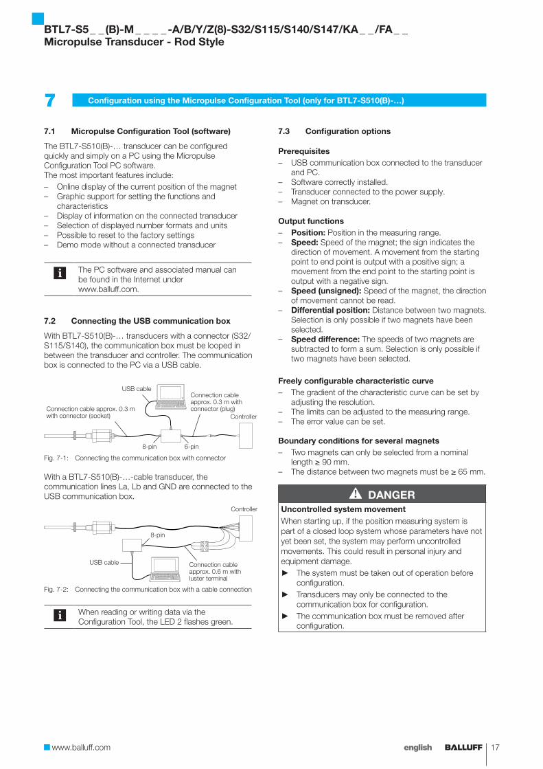
The BTL7-S510(B)-… transducer can be configured quickly and simply on a PC using the Micropulse Configuration Tool PC software.The most important features include:– Online display of the current position of the magnet– Graphic support for setting the functions and
characteristics– Display of information on the connected transducer– Selection of displayed number formats and units– Possible to reset to the factory settings– Demo mode without a connected transducer
The PC software and associated manual can be found in the Internet under www.balluff.com.
7.2 Connecting the USB communication box
With BTL7-S510(B)-… transducers with a connector (S32/S115/S140), the communication box must be looped in between the transducer and controller. The communication box is connected to the PC via a USB cable.
Fig. 7-1: Connecting the communication box with connector
With a BTL7-S510(B)-…-cable transducer, the communication lines La, Lb and GND are connected to the USB communication box.
Fig. 7-2: Connecting the communication box with a cable connection
When reading or writing data via the Configuration Tool, the LED 2 flashes green.
7.3 Configuration options
Prerequisites– USB communication box connected to the transducer
and PC.– Software correctly installed.– Transducer connected to the power supply.– Magnet on transducer.
Output functions– Position: Position in the measuring range.– Speed: Speed of the magnet; the sign indicates the
direction of movement. A movement from the starting point to end point is output with a positive sign; a movement from the end point to the starting point is output with a negative sign.
– Speed (unsigned): Speed of the magnet, the direction of movement cannot be read.
– Differential position: Distance between two magnets. Selection is only possible if two magnets have been selected.
– Speed difference: The speeds of two magnets are subtracted to form a sum. Selection is only possible if two magnets have been selected.
Freely configurable characteristic curve– The gradient of the characteristic curve can be set by
adjusting the resolution.– The limits can be adjusted to the measuring range.– The error value can be set.
Boundary conditions for several magnets– Two magnets can only be selected from a nominal
length ≥ 90 mm.– The distance between two magnets must be ≥ 65 mm.
DANGERUncontrolled system movementWhen starting up, if the position measuring system is part of a closed loop system whose parameters have not yet been set, the system may perform uncontrolled movements. This could result in personal injury and equipment damage.
► The system must be taken out of operation before configuration.
► Transducers may only be connected to the communication box for configuration.
► The communication box must be removed after configuration.
USB cable
6-pin8-pin
Connection cable approx. 0.3 m with connector (socket)
Connection cable approx. 0.3 m with connector (plug)
Controller
8-pin
USB cable
Controller
Connection cable approx. 0.6 m with luster terminal
BTL7-S5 _ _ (B)-M _ _ _ _ -A/B/Y/Z(8)-S32/S115/S140/S147/KA _ _ /FA _ _Micropulse Transducer - Rod Style
18 english
8.1 Accuracy
The specifications are typical values for BTL7-S… at 24 V DC, at room temperature, and with a nominal length of 500 mm in conjunction with the BTL-P-1013-4R, BTL-P-1013-4S, BTL-P-1012-4R or BTL-P-1014-2R magnet.The transducer is fully operational immediately, with full accuracy after warm-up.
For special versions, other technical data may apply.Special versions are indicated by the suffix -SA on the part label.
Position resolution 1, 2, 5, 10, 20, 40, 50, 100 µm
(additionally 200, 500, 1000 µm with BTL7-S510(B)-…)
Non-linearity at
Nominal length 25…5500 mmresolution ≤ 10 µmresolution > 10 µm
≤ ±30 µm≤ ±2 LSB
Nominal length 5501…7620 mm ±0,02 %
Hysteresis ≤ ±7 µm
Repeat accuracy ≤ ±5 µm (typ. ±2.5 µm)
Temperature coefficient1) ≤ 15 ppm/K
Speed resolution 0.1 mm/s
Min. detectable speed 1 mm/s
Max. detectable speed 10 m/s
8.2 Ambient conditions
Operating temperature −40°C…+85°C
Operating temperature for UL(only BTL7…-KA…)
Max. +80°C
Storage temperature −40°C…+100°C
Relative humidity < 90%, non-condensing
Rod pressure rating (when installed in hydraulic cylinders)
For Ø 8 mm < 250 barFor Ø 10.2 mm < 600 bar
Shock rating Continuous shock per EN 60068-2-273)
150 g/6 ms150 g/2 ms
2)
Vibration per EN 60068-2-63) (note resonant frequency of the rod)
20 g, 10…2000 Hz
Degree of protection per IEC 60529
Connector S32/S115/S147 (when attached)
IP67
Connector S140 (when attached)
IP65
Cable IP683)
8.3 Supply voltage
Voltage, stabilized4) 10…30 V DC
Ripple ≤ 0.5 Vss
Current draw (at 24 V DC) ≤ 120 mA
Inrush current ≤ 500 mA
Reverse polarity protection Up to 36 V (supply to GND)
Overvoltage protection Up to 36 V
Dielectric strength (GND to housing)
500 V DC
8.4 Communication lines La, Lb
Short-circuit protection Signal cable to GND
1) Nominal length 500 mm, magnet in the middle of the measuring range2) For : Use in enclosed spaces and up to a height of 2000 m above sea
level.3) Individual specifications as per Balluff factory standard, resonances
excluded4) For : The transducer must be externally connected via a limited-
energy circuit as defined in UL 61010-1, a low-power source as defined in
UL 60950-1, or a class 2 power supply as defined in UL 1310 or
UL 1585.
8 Technical data
BTL7-S5 _ _ (B)-M _ _ _ _ -A/B/Y/Z(8)-S32/S115/S140/S147/KA _ _ /FA _ _Micropulse Transducer - Rod Style
www.balluff.com 19english
8.5 Output
Configurable bit number (only BTL7-S510(B)-…)
16-32
Coding Binary or Gray
Characteristic Rising or falling
SSI data Position, speed, absolute speed, differential position, speed difference (between 2 magnets), error value
SSI clock frequency fClk 10 kHz…1 MHz
Behavior at null point BTL7 standard:No negative values between flange and null point
BTL7-S510(B)-…:Configurable
Short-circuit protection Signal lines Data+/−, Clk+/− to +36 V or GND
8.6 Dimensions, weights
Rod diameter 8 mm or 10.2 mm
Nominal lengthFor Ø 8 mm 25…1016 mmFor Ø 10.2 mm 25…7620 mm
Weight (depends on length)
Approx. 2 kg/m
Housing material Aluminum
Flange material Stainless steel
Rod material Stainless steel
Rod wall thicknessFor Ø 8 mm 0.9 mmFor Ø 10.2 mm 2 mm
Young's modulus Approx. 200 kN/mm2
Housing mounting via threads
M18×1.5 or 3/4"-16UNF
Tightening torque Max. 100 Nm
8 Technical data (continued)
BTL7-…-KA_ _
Cable material PURcULus 2054980 °C, 300 V, internal wiring
Cable temperature –40°C…+90°C
Cable diameter Max. 7 mm
Permissible bending radius
Fixed routing ≥ 35 mmMovable ≥ 105 mm
BTL7-…-FA_ _
Cable material PTFENo UL approval available
Cable temperature –55°C…+200°C
Cable diameter Max. 7 mm
Permissible bending radius
Fixed routing ≥ 35 mmMovable No permissible bending
radius
BTL7-S5 _ _ (B)-M _ _ _ _ -A/B/Y/Z(8)-S32/S115/S140/S147/KA _ _ /FA _ _Micropulse Transducer - Rod Style
20 english
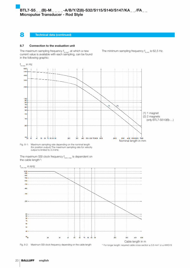
8.7 Connection to the evaluation unit
The maximum sampling frequency fA,max, at which a new current value is available with each sampling, can be found in the following graphic:
Fig. 8-1: Maximum sampling rate depending on the nominal length (for position output) The maximum sampling rate for velocity output is limited to 3.3 kHz.
The maximum SSI clock frequency fCLK, max is dependent on the cable length1):
Fig. 8-2: Maximum SSI clock frequency depending on the cable length
fA,max in Hz
Nominal length in mm
(1) 1 magnet(2) 2 magnets (only BTL7-S510(B)-…)
Cable length in m
fClk,max in kHz
8 Technical data (continued)
1) For longer length: required cable cross-section ≥ 0.6 mm2 or ≤ AWG19
BTL7-S5 _ _ (B)-M _ _ _ _ -A/B/Y/Z(8)-S32/S115/S140/S147/KA _ _ /FA _ _Micropulse Transducer - Rod Style
The minimum sampling frequency fA,min is 62,5 Hz.
www.balluff.com 21english
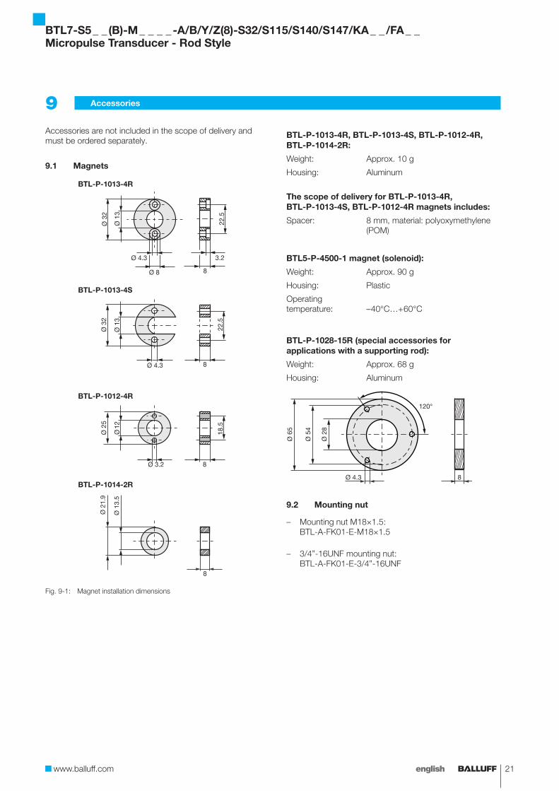
Accessories are not included in the scope of delivery and must be ordered separately.
9.1 Magnets
Fig. 9-1:
BTL-P-1013-4R
BTL-P-1013-4S
BTL-P-1012-4R
BTL-P-1014-2R
BTL-P-0814-GR-PAFMagnet installation dimensions
BTL-P-1013-4R, BTL-P-1013-4S, BTL-P-1012-4R, BTL-P-1014-2R:
Weight: Approx. 10 g
Housing: Aluminum
The scope of delivery for BTL-P-1013-4R, BTL-P-1013-4S, BTL-P-1012-4R magnets includes:
Spacer: 8 mm, material: polyoxymethylene (POM)
BTL5-P-4500-1 magnet (solenoid):
Weight: Approx. 90 g
Housing: Plastic
Operating temperature:
– 40°C…+ 60°C
BTL-P-1028-15R (special accessories for applications with a supporting rod):
Weight: Approx. 68 g
Housing: Aluminum
Ø 4.3
120°
Ø 2
8
Ø 5
4
Ø 6
5
8
9.2 Mounting nut
– Mounting nut M18×1.5: BTL-A-FK01-E-M18×1.5
– 3/4”-16UNF mounting nut: BTL-A-FK01-E-3/4”-16UNF
9 Accessories
BTL7-S5 _ _ (B)-M _ _ _ _ -A/B/Y/Z(8)-S32/S115/S140/S147/KA _ _ /FA _ _Micropulse Transducer - Rod Style
22 english
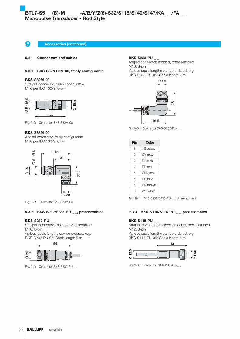
9.3 Connectors and cables
9.3.1 BKS-S32/S33M-00, freely configurable
BKS-S32M-00Straight connector, freely configurableM16 per IEC 130-9, 8-pin
Fig. 9-2:
~ 62
Connector BKS-S32M-00
BKS-S33M-00Angled connector, freely configurableM16 per IEC 130-9, 8-pin
Fig. 9-3:
Ø 1
8
31
37.2
Ø 20
Ø 6
- Ø
8 ~ 54
Connector BKS-S33M-00
9.3.2 BKS-S232/S233-PU-_ _, preassembled
BKS-S232-PU-_ _Straight connector, molded, preassembledM16, 8-pinVarious cable lengths can be ordered, e.g. BKS-S232-PU-05: Cable length 5 m
Fig. 9-4:
Ø 2
0
66
Connector BKS-S232-PU-_ _
BKS-S233-PU-_ _Angled connector, molded, preassembledM16, 8-pinVarious cable lengths can be ordered, e.g. BKS-S233-PU-05: Cable length 5 m
Fig. 9-5:
Ø 20
46
48.5
Connector BKS-S233-PU-_ _
Pin Color
1 YE yellow
2 GY gray
3 PK pink
4 RD red
5 GN green
6 BU blue
7 BN brown
8 WH white
Tab. 9-1: BKS-S232/S233-PU-_ _ pin assignment
9.3.3 BKS-S115/S116-PU-_ _, preassembled
BKS-S115-PU-_ _Straight connector, molded-on cable, preassembledM12, 8-pinVarious cable lengths can be ordered, e.g. BKS-S115-PU-05: Cable length 5 m
Fig. 9-6:
43
Ø 1
3.5
M12
x1
Connector BKS-S115-PU-_ _
9 Accessories (continued)
BTL7-S5 _ _ (B)-M _ _ _ _ -A/B/Y/Z(8)-S32/S115/S140/S147/KA _ _ /FA _ _Micropulse Transducer - Rod Style
www.balluff.com 23english
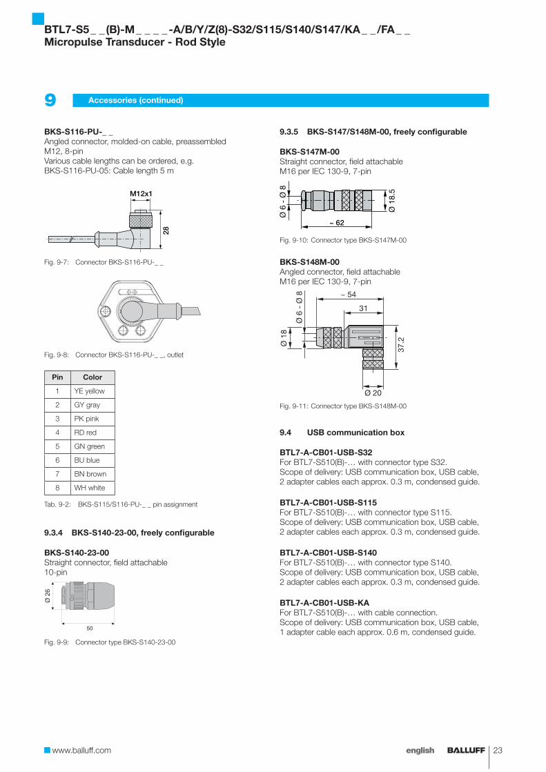
9 Accessories (continued)
BKS-S116-PU-_ _Angled connector, molded-on cable, preassembledM12, 8-pinVarious cable lengths can be ordered, e.g. BKS-S116-PU-05: Cable length 5 m
Fig. 9-7:
28
M12x1
Connector BKS-S116-PU-_ _
Fig. 9-8: Connector BKS-S116-PU-_ _, outlet
Pin Color
1 YE yellow
2 GY gray
3 PK pink
4 RD red
5 GN green
6 BU blue
7 BN brown
8 WH white
Tab. 9-2: BKS-S115/S116-PU-_ _ pin assignment
9.3.4 BKS-S140-23-00, freely configurable
BKS-S140-23-00Straight connector, field attachable10-pin
Fig. 9-9:
50
Ø 2
6
Connector type BKS-S140-23-00
9.3.5 BKS-S147/S148M-00, freely configurable
BKS-S147M-00Straight connector, field attachableM16 per IEC 130-9, 7-pin
Fig. 9-10:
~ 62
Connector type BKS-S147M-00
BKS-S148M-00Angled connector, field attachableM16 per IEC 130-9, 7-pin
Fig. 9-11:
Ø 1
8
31
37.2
Ø 20
Ø 6
- Ø
8 ~ 54
Connector type BKS-S148M-00
9.4 USB communication box
BTL7-A-CB01-USB-S32For BTL7-S510(B)-… with connector type S32.Scope of delivery: USB communication box, USB cable, 2 adapter cables each approx. 0.3 m, condensed guide.
BTL7-A-CB01-USB-S115For BTL7-S510(B)-… with connector type S115.Scope of delivery: USB communication box, USB cable, 2 adapter cables each approx. 0.3 m, condensed guide.
BTL7-A-CB01-USB-S140For BTL7-S510(B)-… with connector type S140.Scope of delivery: USB communication box, USB cable, 2 adapter cables each approx. 0.3 m, condensed guide.
BTL7-A-CB01-USB-KAFor BTL7-S510(B)-… with cable connection.Scope of delivery: USB communication box, USB cable, 1 adapter cable each approx. 0.6 m, condensed guide.
BTL7-S5 _ _ (B)-M _ _ _ _ -A/B/Y/Z(8)-S32/S115/S140/S147/KA _ _ /FA _ _Micropulse Transducer - Rod Style
24 english
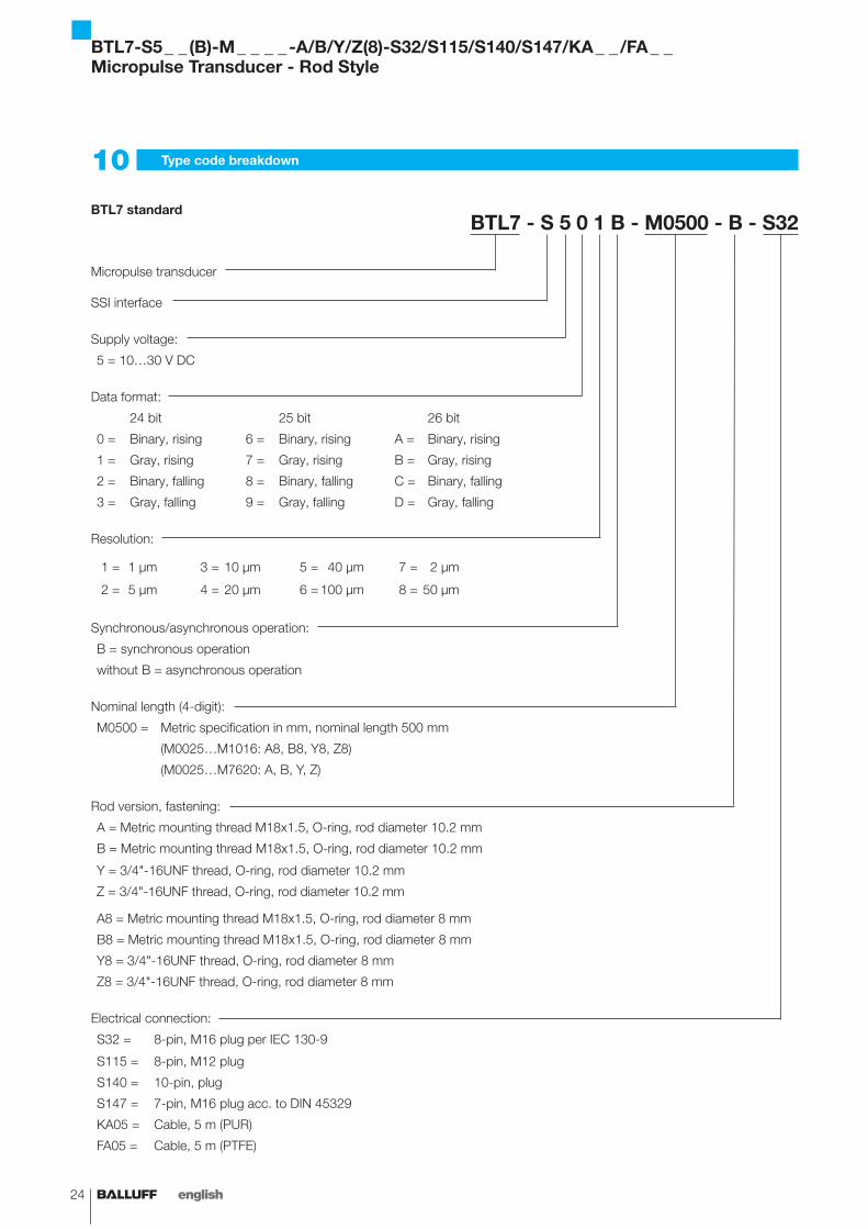
10 Type code breakdown
BTL7 standardBTL7 - S 5 0 1 B - M0500 - B - S32
Micropulse transducer
SSI interface
Supply voltage:
5 = 10…30 V DC
Data format:
24 bit 25 bit 26 bit
0 = Binary, rising 6 = Binary, rising A = Binary, rising
1 = Gray, rising 7 = Gray, rising B = Gray, rising
2 = Binary, falling 8 = Binary, falling C = Binary, falling
3 = Gray, falling 9 = Gray, falling D = Gray, falling
Resolution:
1 = 1 µm 3 = 10 µm 5 = 40 µm 7 = 2 µm
2 = 5 µm 4 = 20 µm 6 = 100 µm 8 = 50 µm
Synchronous/asynchronous operation:
B = synchronous operation
without B = asynchronous operation
Nominal length (4-digit):
M0500 = Metric specification in mm, nominal length 500 mm
(M0025…M1016: A8, B8, Y8, Z8)
(M0025…M7620: A, B, Y, Z)
Rod version, fastening:
A = Metric mounting thread M18x1.5, O-ring, rod diameter 10.2 mm
B = Metric mounting thread M18x1.5, O-ring, rod diameter 10.2 mm
Y = 3/4"-16UNF thread, O-ring, rod diameter 10.2 mm
Z = 3/4"-16UNF thread, O-ring, rod diameter 10.2 mm
A8 = Metric mounting thread M18x1.5, O-ring, rod diameter 8 mm
B8 = Metric mounting thread M18x1.5, O-ring, rod diameter 8 mm
Y8 = 3/4"-16UNF thread, O-ring, rod diameter 8 mm
Z8 = 3/4"-16UNF thread, O-ring, rod diameter 8 mm
Electrical connection:
S32 = 8-pin, M16 plug per IEC 130-9
S115 = 8-pin, M12 plug
S140 = 10-pin, plug
S147 = 7-pin, M16 plug acc. to DIN 45329
KA05 = Cable, 5 m (PUR)
FA05 = Cable, 5 m (PTFE)
BTL7-S5 _ _ (B)-M _ _ _ _ -A/B/Y/Z(8)-S32/S115/S140/S147/KA _ _ /FA _ _Micropulse Transducer - Rod Style
www.balluff.com 25english
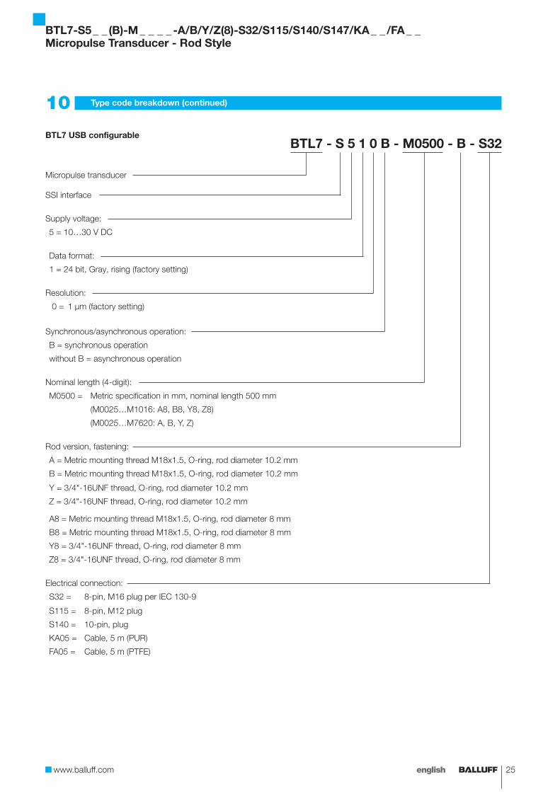
10 Type code breakdown (continued)
BTL7 USB configurableBTL7 - S 5 1 0 B - M0500 - B - S32
Micropulse transducer
SSI interface
Supply voltage:
5 = 10…30 V DC
Data format:
1 = 24 bit, Gray, rising (factory setting)
Resolution:
0 = 1 µm (factory setting)
Synchronous/asynchronous operation:
B = synchronous operation
without B = asynchronous operation
Nominal length (4-digit):
M0500 = Metric specification in mm, nominal length 500 mm
(M0025…M1016: A8, B8, Y8, Z8)
(M0025…M7620: A, B, Y, Z)
Rod version, fastening:
A = Metric mounting thread M18x1.5, O-ring, rod diameter 10.2 mm
B = Metric mounting thread M18x1.5, O-ring, rod diameter 10.2 mm
Y = 3/4"-16UNF thread, O-ring, rod diameter 10.2 mm
Z = 3/4"-16UNF thread, O-ring, rod diameter 10.2 mm
A8 = Metric mounting thread M18x1.5, O-ring, rod diameter 8 mm
B8 = Metric mounting thread M18x1.5, O-ring, rod diameter 8 mm
Y8 = 3/4"-16UNF thread, O-ring, rod diameter 8 mm
Z8 = 3/4"-16UNF thread, O-ring, rod diameter 8 mm
Electrical connection:
S32 = 8-pin, M16 plug per IEC 130-9
S115 = 8-pin, M12 plug
S140 = 10-pin, plug
KA05 = Cable, 5 m (PUR)
FA05 = Cable, 5 m (PTFE)
BTL7-S5 _ _ (B)-M _ _ _ _ -A/B/Y/Z(8)-S32/S115/S140/S147/KA _ _ /FA _ _Micropulse Transducer - Rod Style

26 english
11.1 Converting units of length
1 mm = 0.0393700787 inch
mm inches
1 0.03937008
2 0.07874016
3 0.11811024
4 0.15748031
5 0.19685039
6 0.23622047
7 0.27559055
8 0.31496063
9 0.35433071
10 0.393700787
Tab. 11-1: Conversion table mm to inches
1 inch = 25.4 mm
inches mm
1 25.4
2 50.8
3 76.2
4 101.6
5 127
6 152.4
7 177.8
8 203.2
9 228.6
10 254
Tab. 11-2: Conversion table inches to mm
11.2 Product labels
Fig. 11-1: Standard BTL7 product label
Fig. 11-2: BTL7-S510-… product label
11 Appendix
Ordering code
Type code
Serial number
Ordering code
Type code
Serial number
BTL7-S5 _ _ (B)-M _ _ _ _ -A/B/Y/Z(8)-S32/S115/S140/S147/KA _ _ /FA _ _Micropulse Transducer - Rod Style

www.balluff.com
Headquarters GermanyBalluff GmbHSchurwaldstrasse 973765 Neuhausen a.d.F.Phone + 49 7158 173-0Fax +49 7158 [email protected]
Global Service Center
GermanyBalluff GmbHSchurwaldstrasse 973765 Neuhausen a.d.F.Phone +49 7158 173-370Fax +49 7158 [email protected]
US Service Center
USABalluff Inc.8125 Holton DriveFlorence, KY 41042Phone (859) 727-2200Toll-free 1-800-543-8390Fax (859) 727-4823 [email protected]
CN Service Center
ChinaBalluff (Shanghai) trading Co., ltd.Room 1006, Pujian Rd. 145. Shanghai, 200127, P.R. China Phone +86 (21) 5089 9970Fax +86 (21) 5089 [email protected]
No.
868
142-
726
EN
. 03
.120
893
. K15
; sub
ject
to m
odifi
catio
n. R
epla
ces
G15
.