Embed Size (px)
Citation preview
U s e r ’ s G u i d e V R X 9 3 2 L A P
V R X 9 1 8 S P
V R X - A F
VRX_Powered_UsersGuid012808 copy 3.qxp 1/30/08 4:52 PM Page 1

2
VRX_Powered_UsersGuid012808 copy 3.qxp 1/30/08 4:52 PM Page 2
3
PATENTSVRX series products are manufactured and sold under U.S. patents 5,748,760; 6,112,847; 6,394,223; 6,847,726;6,774,510; D483,743; and 6,768,806.
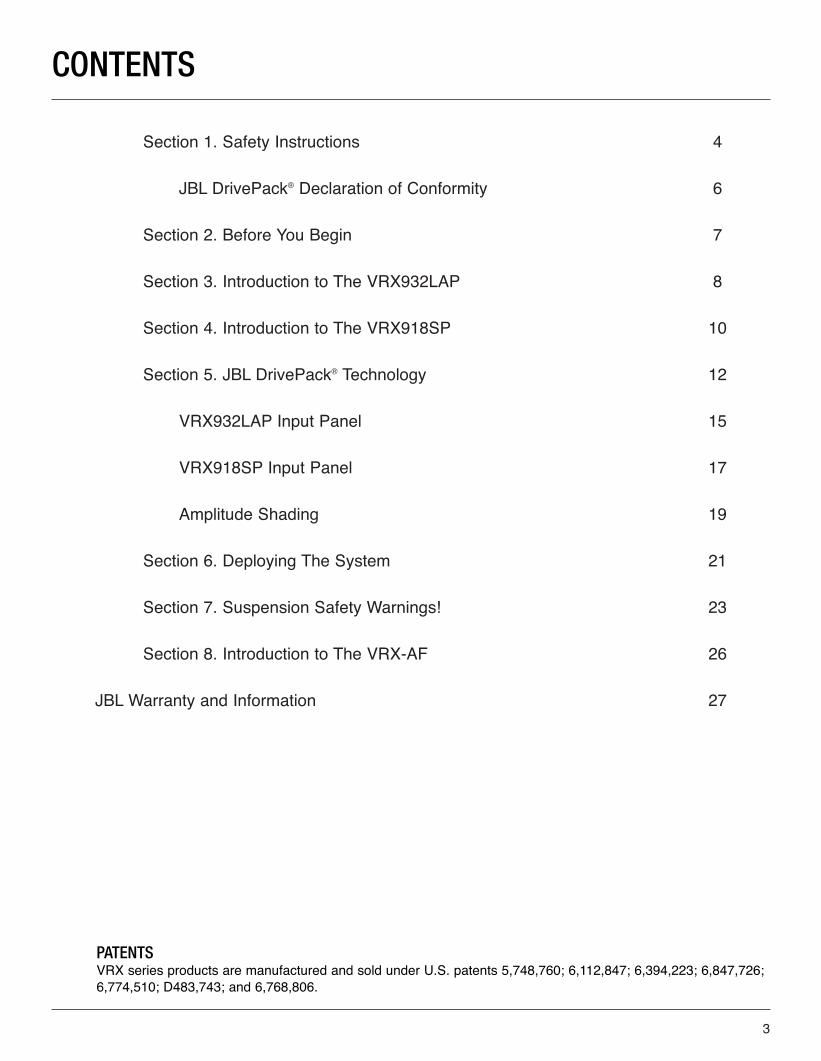
CONTENTS
Section 1. Safety Instructions 4
JBL DrivePack® Declaration of Conformity 6
Section 2. Before You Begin 7
Section 3. Introduction to The VRX932LAP 8
Section 4. Introduction to The VRX918SP 10
Section 5. JBL DrivePack® Technology 12
VRX932LAP Input Panel 15
VRX918SP Input Panel 17
Amplitude Shading 19
Section 6. Deploying The System 21
Section 7. Suspension Safety Warnings! 23
Section 8. Introduction to The VRX-AF 26
JBL Warranty and Information 27
VRX_Powered_UsersGuid012808 copy 3.qxp 1/30/08 4:52 PM Page 3

4
IMPORTANT SAFETY INSTRUCTIONS
1. Read these instructions.
2. Keep these instructions.
3. Heed all warnings.
4. Follow all instructions.
5. Do not use this apparatus near water.
6. Clean only with dry cloth.
7. Do not block any ventilation openings. Install in accordance with the manufacturer's instructions.
8. Do not install near any heat sources such as radiators, heat registers, stoves, or other apparatus (including amplifiers) that produce heat.
9. Do not defeat the safety purpose of the polarized or grounding-type plug. A polarized plug has two blades with one wider than the other. A grounding-type plug has two blades and a third grounding prong. The wide blade or the third prong are provided for your safety. If the provided plug does not fit into your outlet, consult an electrician for replacement of the obsolete outlet.
10. Protect the power cord from being walked on or pinched, particularly at plugs, convenience receptacles, and the point where they exit from the apparatus.
11. Only use attachments/accessories specified by the manufacturer.
12. Use only with the cart, stand, tripod, bracket, or table specified by the manufacturer, or sold with the apparatus. When a cart is used, use caution when moving the cart/apparatus combination to avoid injury from tip-over.
13. Unplug this apparatus during lightning storms or when unused for long periods of time.
14. Refer all servicing to qualified service personnel. Servicing is required when the apparatus has been damaged in any way, such as power supply cord or plug is damaged, liquid has been spilled or objects have fallen into the apparatus, the apparatus has been exposed to rain or moisture, does not operate normally, or has been dropped.
15. WARNING: To reduce the risk of fire or electric shock, do not expose this apparatus to rain or moisture.
16. Do not expose this equipment to dripping or splashing and ensure that no objects filled with liquids, such as vases, are placed on the equipment.
17. To completely disconnect this apparatus from the AC Mains, disconnect the power supply cord plugfrom the AC receptacle.
18. The mains plug of the power supply cord shall remain readily operable.
SECTION 1. SAFETY INSTRUCTIONS
VRX_Powered_UsersGuid012808 copy 3.qxp 1/30/08 4:52 PM Page 4
5
THIS APPARATUS CONTAINS POTENTIALLY LETHAL VOLTAGES. TO PREVENT ELECTRIC SHOCK ORHAZARD, DO NOT REMOVE DRIVEPACK CHASSIS, INPUT MODULE OR AC INPUT COVERS. NO USERSERVICEABLE PARTS INSIDE. REFER SERVICING TO QUALIFIED SERVICE PERSONNEL.
WATCH FOR THESE SYMBOLS
The lightning bolt triangle is used to alert the user to the risk of electric shock.
The exclamation point triangle is used to alert the user to important operating or maintenanceinstructions.
FCC COMPLIANCE NOTICE
This device complies with part 15 of the FCC rules. Operation is subject to the following two conditions: (1) Thisdevice may not cause harmful interference, and (2) this device must accept any interference received, includinginterference that may cause undesired operation.
CAUTION: Changes or modifications not expressly approved by the party responsible for compliance could voidthe user's authority to operate the equipment.
CSA COMPLIANCE NOTICE
CSA Certification Applies to Amplifier Module.
VRX_Powered_UsersGuid012808 copy 3.qxp 1/30/08 4:52 PM Page 5
6
SAFETY AND EMC COMPLIANCE SPECIFICATIONS
EN 55103-1:1997 Electromagnetic Compatibility - Product Family Standard for Audio, Video, Audio-Visual land Entertainment Lighting Control Apparatus for Professional Use, Part 1: Emissions
EN 55103-1:1997 Magnetic Field Emissions-Annex A @ 10 cm and 1 M
EN 55022:2003 Limits and Methods of Measurement of Radio Disturbance Characteristics of ITE: Radiated, Class B Limits; Conducted, Class A
EN 55103-2:1997 Electromagnetic Compatibility - Product Family Standard for Audio, Video, Audio-Visual and Entertainment Lighting Control Apparatus for Professional Use, Part 2: Immunity
EN 61000-4-2: A2:2001 Electrostatic Discharge Immunity (Environment E2-criteria B, 4 kV Contact, 8 kV Air discharge)
EN 61000-4-3:2003 Radiated, Radio-frequency, Electromagnetic Immunity (Environment E2, criteria A)
EN61000-4-4:2005 Electrical Fast Transient/Burst Immunity (criteria B)
EN 61000-4-5:2001 Surge Immunity (criteria B)
EN 61000-4-6:1996 Immunity to Conducted Disturbances Induced by Radio-Frequency Fields (criteria A)
EN 61000-4-11:2004 Voltage Dips, Short Interruptions and Voltage Variation
UL 6500 2nd Edition 1999 Audio/Video and Musical Instrument Apparatus for Household, Commercial and Similar General Use
CAN/CSA E60065-00 Audio, Video and Similar Electronic Apparatus - Safety Requirements
JBL DRIVEPACK® DECLARATION OF CONFORMITY
VRX_Powered_UsersGuid012808 copy 3.qxp 1/30/08 4:52 PM Page 6
7
The VRX Series loudspeakers covered by this manual are not intended for fixed installation in outdoor or highmoisture environments. Moisture can damage the speaker cone and surround and cause corrosion of electricalcontacts and metal parts. Avoid exposing the speakers to direct moisture. Keep loudspeakers out of extended orintense direct sunlight. The driver suspension will prematurely dry out and finished surfaces may be degraded bylong-term exposure to intense ultra-violet (UV) light.
The VRX Series loudspeakers can generate considerable energy. When placed on a slippery surface such aspolished wood or linoleum, the speaker may move due to its acoustical energy output. Precautions should betaken to assure that the speaker does not fall off a stage or table on which it is placed.
Make sure the selected AC line voltage is correct.
STAND MOUNTING SAFETY PRECAUTIONS
Some VRX Series models can be used with an optional stand mount accessory allowing mounting on tripodstands or on a pole over subwoofers. When using stands or poles, be sure to observe the following precautions:
• Check the stand or pole specification to be certain the device is designed to support the weight of the speaker. Observe all safety precautions specified by the manufacturer.
• Always verify that the stand (or subwoofer / pole) is placed on a flat, level, and stable surface and be sure to fully extend the legs of tripod type stands. Position the stand so that the legs do not present a trip hazard.
• Route cables so that performers, production crew, and audience will not trip over them and pull the speaker over.
• Inspect the stand (or pole and associated hardware) before each use and do not use equipment with worn, damaged, or missing parts.
• Do not attempt to place more than two VRX932LAP Series loudspeaker on a stand or pole.
• Always be cautious in windy, outdoor conditions. It may be necessary to place additional weight (i.e. sandbags) on the base of the stand to improve stability. Avoid attaching banners or similar items to any part of a speaker system. Such attachments could act as a sail and topple the system.
• Unless you are confident that you can handle the weight of the speaker, ask another person to help you get it onto the tripod stand or pole.
HEARING DAMAGE, PROLONGED EXPOSURE TO EXCESSIVE SPL
VRX Series loudspeakers are easily capable of generating sound pressure levels (SPL) sufficient to cause permanent hearing damage to performers, production crew and audience members. Caution should be taken toavoid prolonged exposure to SPL in excess of 90 dB.
SECTION 2 : BEFORE YOU BEGIN
VRX_Powered_UsersGuid012808 copy 3.qxp 1/30/08 4:52 PM Page 7
8
SECTION 3 : INTRODUCTION TO THE VRX932LAP
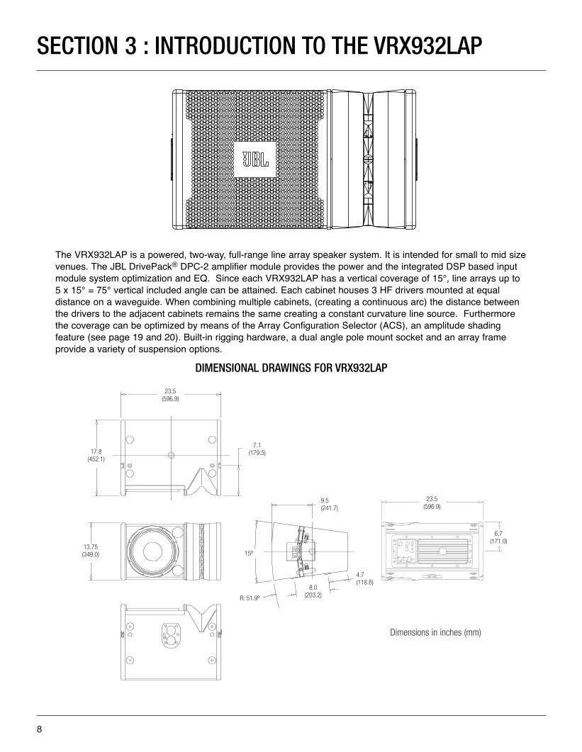
The VRX932LAP is a powered, two-way, full-range line array speaker system. It is intended for small to mid sizevenues. The JBL DrivePack® DPC-2 amplifier module provides the power and the integrated DSP based inputmodule system optimization and EQ. Since each VRX932LAP has a vertical coverage of 15°, line arrays up to5 x 15° = 75° vertical included angle can be attained. Each cabinet houses 3 HF drivers mounted at equal distance on a waveguide. When combining multiple cabinets, (creating a continuous arc) the distance betweenthe drivers to the adjacent cabinets remains the same creating a constant curvature line source. Furthermorethe coverage can be optimized by means of the Array Configuration Selector (ACS), an amplitude shading feature (see page 19 and 20). Built-in rigging hardware, a dual angle pole mount socket and an array frame provide a variety of suspension options.
DIMENSIONAL DRAWINGS FOR VRX932LAP
23.5 (596.9)
R: 51.9º
7.1 (179.5)17.8
(452.1)
13.75 (349.0)
8.0 (203.2)
4.7 (118.6)
9.5(241.7)
15º
23.5 (596.9)
6.7 (171.0)
Dimensions in inches (mm)
VRX_Powered_UsersGuid012808 copy 3.qxp 1/30/08 4:52 PM Page 8
9
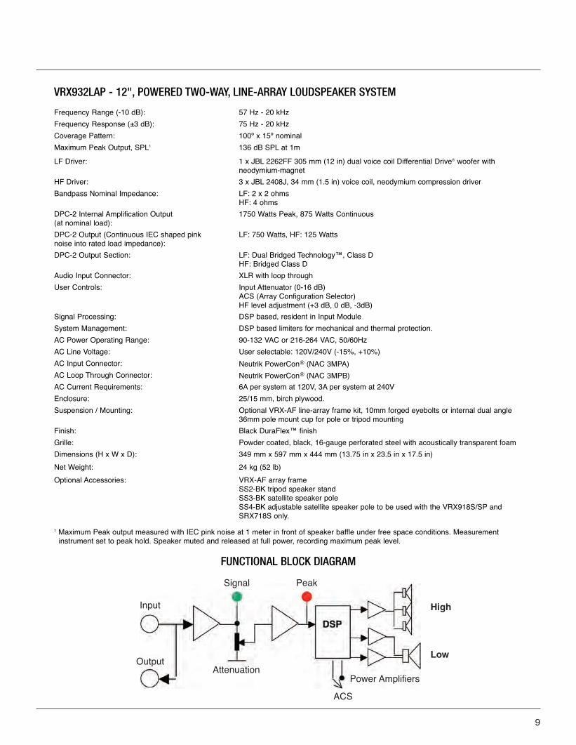
VRX932LAP - 12", POWERED TWO-WAY, LINE-ARRAY LOUDSPEAKER SYSTEM
FUNCTIONAL BLOCK DIAGRAM
Frequency Range (-10 dB): 57 Hz - 20 kHz
Frequency Response (±3 dB): 75 Hz - 20 kHz
Coverage Pattern: 100º x 15º nominal
Maximum Peak Output, SPL1 136 dB SPL at 1m
LF Driver: 1 x JBL 2262FF 305 mm (12 in) dual voice coil Differential Drive® woofer withneodymium-magnet
HF Driver: 3 x JBL 2408J, 34 mm (1.5 in) voice coil, neodymium compression driver
Bandpass Nominal Impedance: LF: 2 x 2 ohmsHF: 4 ohms
DPC-2 Internal Amplification Output (at nominal load):
1750 Watts Peak, 875 Watts Continuous
DPC-2 Output (Continuous IEC shaped pink noise into rated load impedance):
LF: 750 Watts, HF: 125 Watts
DPC-2 Output Section: LF: Dual Bridged Technology™, Class DHF: Bridged Class D
Audio Input Connector: XLR with loop through
User Controls: Input Attenuator (0-16 dB) ACS (Array Configuration Selector)HF level adjustment (+3 dB, 0 dB, -3dB)
Signal Processing: DSP based, resident in Input Module
System Management: DSP based limiters for mechanical and thermal protection.
AC Power Operating Range: 90-132 VAC or 216-264 VAC, 50/60Hz
AC Line Voltage: User selectable: 120V/240V (-15%, +10%)
AC Input Connector: Neutrik PowerCon® (NAC 3MPA)
AC Loop Through Connector: Neutrik PowerCon® (NAC 3MPB)
AC Current Requirements: 6A per system at 120V, 3A per system at 240V
Enclosure: 25/15 mm, birch plywood.
Suspension / Mounting: Optional VRX-AF line-array frame kit, 10mm forged eyebolts or internal dual angle36mm pole mount cup for pole or tripod mounting
Finish: Black DuraFlex™ finish
Grille: Powder coated, black, 16-gauge perforated steel with acoustically transparent foam
Dimensions (H x W x D): 349 mm x 597 mm x 444 mm (13.75 in x 23.5 in x 17.5 in)
Net Weight: 24 kg (52 lb)
Optional Accessories: VRX-AF array frameSS2-BK tripod speaker standSS3-BK satellite speaker poleSS4-BK adjustable satellite speaker pole to be used with the VRX918S/SP andSRX718S only.
1 Maximum Peak output measured with IEC pink noise at 1 meter in front of speaker baffle under free space conditions. Measurement instrument set to peak hold. Speaker muted and released at full power, recording maximum peak level.
Input
Output
Signal Peak
Power Amplifiers
High
Low
ACS
Attenuation
VRX_Powered_UsersGuid012808 copy 3.qxp 1/30/08 4:52 PM Page 9
10
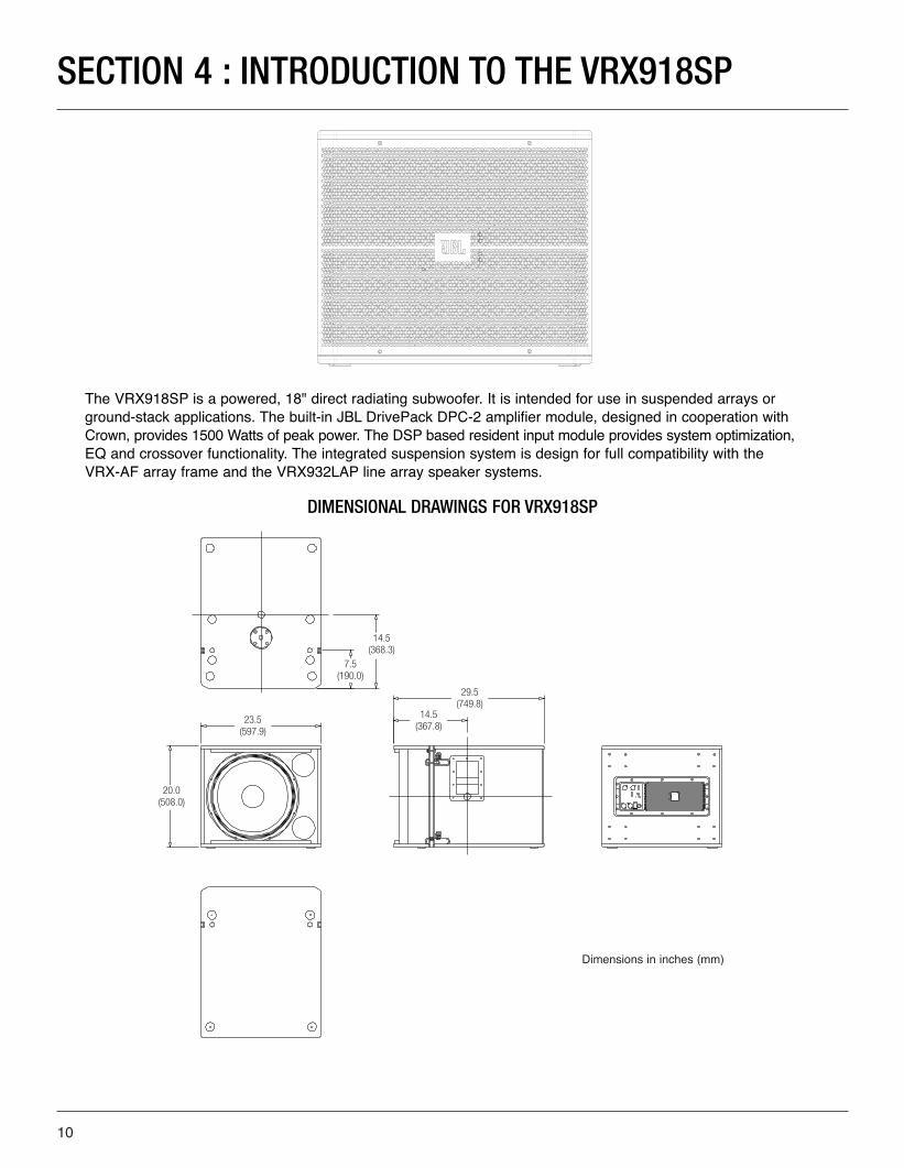
The VRX918SP is a powered, 18" direct radiating subwoofer. It is intended for use in suspended arrays orground-stack applications. The built-in JBL DrivePack DPC-2 amplifier module, designed in cooperation withCrown, provides 1500 Watts of peak power. The DSP based resident input module provides system optimization,EQ and crossover functionality. The integrated suspension system is design for full compatibility with the VRX-AF array frame and the VRX932LAP line array speaker systems.
DIMENSIONAL DRAWINGS FOR VRX918SP
14.5(368.3)
23.5(597.9)
20.0(508.0)
Dimensions in inches (mm)
SECTION 4 : INTRODUCTION TO THE VRX918SP
7.5(190.0)
29.5(749.8)
14.5(367.8)
VRX_Powered_UsersGuid012808 copy 3.qxp 1/30/08 4:52 PM Page 10
11
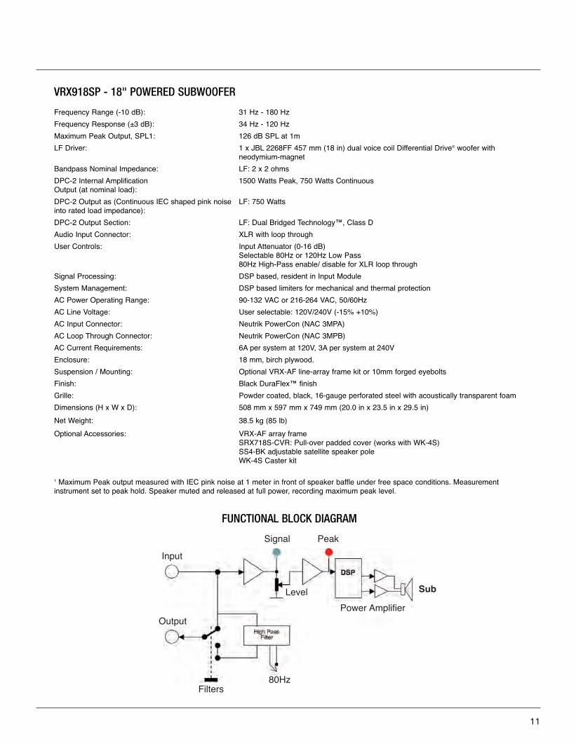
VRX918SP - 18" POWERED SUBWOOFER
Frequency Range (-10 dB): 31 Hz - 180 Hz
Frequency Response (±3 dB): 34 Hz - 120 Hz
Maximum Peak Output, SPL1: 126 dB SPL at 1m
LF Driver: 1 x JBL 2268FF 457 mm (18 in) dual voice coil Differential Drive® woofer withneodymium-magnet
Bandpass Nominal Impedance: LF: 2 x 2 ohms
DPC-2 Internal Amplification Output (at nominal load):
1500 Watts Peak, 750 Watts Continuous
DPC-2 Output as (Continuous IEC shaped pink noiseinto rated load impedance):
LF: 750 Watts
DPC-2 Output Section: LF: Dual Bridged Technology™, Class D
Audio Input Connector: XLR with loop through
User Controls: Input Attenuator (0-16 dB) Selectable 80Hz or 120Hz Low Pass80Hz High-Pass enable/ disable for XLR loop through
Signal Processing: DSP based, resident in Input Module
System Management: DSP based limiters for mechanical and thermal protection
AC Power Operating Range: 90-132 VAC or 216-264 VAC, 50/60Hz
AC Line Voltage: User selectable: 120V/240V (-15% +10%)
AC Input Connector: Neutrik PowerCon (NAC 3MPA)
AC Loop Through Connector: Neutrik PowerCon (NAC 3MPB)
AC Current Requirements: 6A per system at 120V, 3A per system at 240V
Enclosure: 18 mm, birch plywood.
Suspension / Mounting: Optional VRX-AF line-array frame kit or 10mm forged eyebolts
Finish: Black DuraFlex™ finish
Grille: Powder coated, black, 16-gauge perforated steel with acoustically transparent foam
Dimensions (H x W x D): 508 mm x 597 mm x 749 mm (20.0 in x 23.5 in x 29.5 in)
Net Weight: 38.5 kg (85 lb)
Optional Accessories: VRX-AF array frameSRX718S-CVR: Pull-over padded cover (works with WK-4S)SS4-BK adjustable satellite speaker poleWK-4S Caster kit
1 Maximum Peak output measured with IEC pink noise at 1 meter in front of speaker baffle under free space conditions. Measurement instrument set to peak hold. Speaker muted and released at full power, recording maximum peak level.
FUNCTIONAL BLOCK DIAGRAM
Input
Output
Filters80Hz
Signal Peak
Level Sub
Power Amplifier
VRX_Powered_UsersGuid012808 copy 3.qxp 1/30/08 4:52 PM Page 11
12
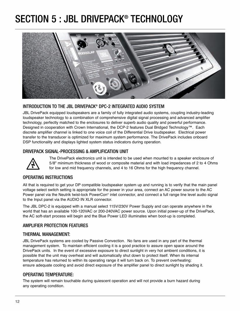
INTRODUCTION TO THE JBL DRIVEPACK® DPC-2 INTEGRATED AUDIO SYSTEMJBL DrivePack equipped loudspeakers are a family of fully integrated audio systems, coupling industry-leadingloudspeaker technology to a combination of comprehensive digital signal processing and advanced amplifiertechnology, perfectly matched to the enclosures to deliver superb audio quality and powerful performance.Designed in cooperation with Crown International, the DCP-2 features Dual Bridged Technology™. Each discrete amplifier channel is linked to one voice coil of the Differential Drive loudspeaker. Electrical power transfer to the transducer is optimized for maximum system performance. The DrivePack includes onboard DSP functionality and displays lighted system status indicators during operation.
DRIVEPACK SIGNAL-PROCESSING & AMPLIFICATION UNIT The DrivePack electronics unit is intended to be used when mounted to a speaker enclosure of5/8" minimum thickness of wood or composite material and with load impedances of 2 to 4 Ohmsfor low and mid frequency channels, and 4 to 16 Ohms for the high frequency channel.
OPERATING INSTRUCTIONS
All that is required to get your DP compatible loudspeaker system up and running is to verify that the main panelvoltage select switch setting is appropriate for the power in your area, connect an AC power source to the ACPower panel via the Neutrik twist-lock PowerCon® inlet connector, and connect a full range line level audio signalto the Input panel via the AUDIO IN XLR connector.
The JBL DPC-2 is equipped with a manual select 115V/230V Power Supply and can operate anywhere in theworld that has an available 100-120VAC or 200-240VAC power source. Upon initial power-up of the DrivePack,the AC soft-start process will begin and the Blue Power LED illuminates when boot-up is completed.
AMPLIFIER PROTECTION FEATURES
THERMAL MANAGEMENT:JBL DrivePack systems are cooled by Passive Convection. No fans are used in any part of the thermal management system. To maintain efficient cooling it is a good practice to assure open space around theDrivePack units. In the event of excessive exposure to direct sunlight in very hot ambient conditions, it is possible that the unit may overheat and will automatically shut down to protect itself. When its internal temperature has returned to within its operating range it will turn back on. To prevent overheating:ensure adequate cooling and avoid direct exposure of the amplifier panel to direct sunlight by shading it.
OPERATING TEMPERATURE:The system will remain touchable during quiescent operation and will not provide a burn hazard during any operating condition.
SECTION 5 : JBL DRIVEPACK® TECHNOLOGY
VRX_Powered_UsersGuid012808 copy 3.qxp 1/30/08 4:52 PM Page 12
13
AC POWER REQUIREMENTS
JBL DrivePack DPC-2 systems are equipped with a DPC-2 multi-channel Dual-Bridged Technology™ power amplifier and loudspeaker specific DSP electronics. The system requires appropriate AC power.
CAUTION:In compliance with safety agency criteria and proper system operation, it is critical that the sys-tem installer observe all electrical safety practices at all times and provide proper earth groundingfor all AC Power connections.
AC POWER CORD KIT
120VAC North America NEMA 5-15 Edison type AC plug to PowerCon® connector and 240V Europe CEE 7/7Schuko type AC plug to PowerCon connector cord sets are provided with this JBL DrivePack product.
One spare gray Neutrik (P/N NAC3FCB) PowerCon connector is included in the AC Power Cord Set for yourconvenience to create a pass-through AC power cable. To create a light-duty pass-through cable the systeminstaller may choose to simply cut off the AC plug from one of the provided AC cord sets and replace it with theprovided Gray PowerCon AC Outlet connector. Follow the wiring convention indicated in Table 1. NOTE: Tighten set screws to 2.5Nm (1.8lb-ft) torque to prevent opening by hand.
CAUTION:In compliance with safety agency criteria and proper system operation, it is critical that the system installer observe all electrical safety practices at all times and provide proper earthgrounding for all AC Power connections.
USER-FABRICATED AC POWER DISTRIBUTIONSystem owners may choose to fabricate or purchase a custom AC Power cable infrastructure optimized for theirspecific JBL DrivePack system configuration. See Table 1 for custom application wiring and connector information. NOTE: Parts not provided.
CAUTION:Do not exceed 80% current rating of any AC connector at any time! See AC Power Rating Tablefor current draw information.
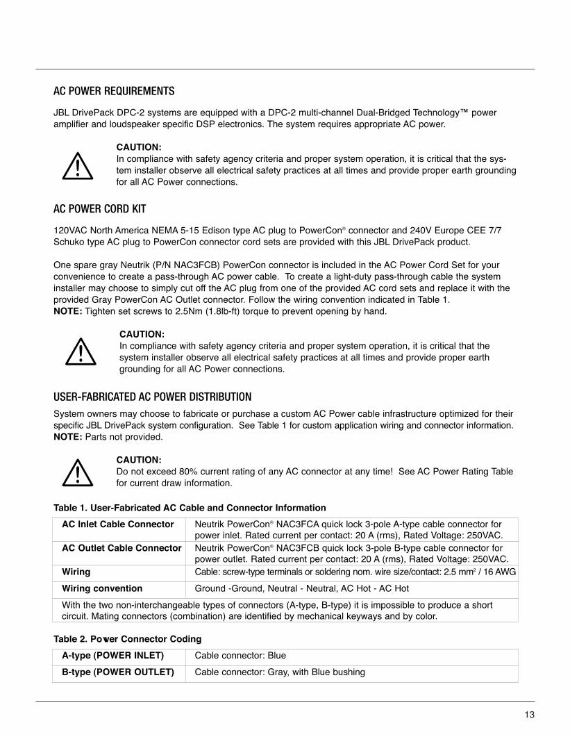
AC Inlet Cable Connector Neutrik PowerCon® NAC3FCA quick lock 3-pole A-type cable connector for power inlet. Rated current per contact: 20 A (rms), Rated Voltage: 250VAC.
AC Outlet Cable Connector Neutrik PowerCon® NAC3FCB quick lock 3-pole B-type cable connector for power outlet. Rated current per contact: 20 A (rms), Rated Voltage: 250VAC.
Wiring Cable: screw-type terminals or soldering nom. wire size/contact: 2.5 mm2 / 16 AWG
Wiring convention Ground -Ground, Neutral - Neutral, AC Hot - AC Hot
With the two non-interchangeable types of connectors (A-type, B-type) it is impossible to produce a short circuit. Mating connectors (combination) are identified by mechanical keyways and by color.
Table 1. User-Fabricated AC Cable and Connector Information
A-type (POWER INLET) Cable connector: Blue
B-type (POWER OUTLET) Cable connector: Gray, with Blue bushing
Table 2. Power Connector Coding
VRX_Powered_UsersGuid012808 copy 3.qxp 1/30/08 4:52 PM Page 13
14
Line Voltage Selection: DrivePack DPC-2 amplifier models feature a user-configurable dual-voltage international power supply and is easily set to the appropriate local AC Power Mains voltage supply. A 2-wayslide switch is provided to select 100-120VAC or 200-240VAC operation, 50/60Hz.
Before you set up your VRX900 Powered series speaker for the first time, verify that the line voltage selectorsetting is appropriate for the AC Mains supply voltage in your area. Applying 230 VAC to the DPC-2 with the unitset to 115V can cause serious damage.
CHANGING THE AC MAINS SUPPLY VOLTAGE SETTING
• Make sure that the speaker is powered off and the AC power cable is disconnected from the speaker.• Locate the voltage selector switch next to the blue PowerCon connector on the main control panel. • Slide the voltage selector switch to 115V for (100-120V~) or 230V for (220-240V~) range setting as
required for your area. • After having reconfirmed that the correct voltage is selected, reconnect the blue AC Line Input
PowerCon connector and power the unit up.
DO NOT UNDER ANY CIRCUMSTANCES OPERATE THE UNIT WITH THE WRONG VOLTAGE SELECTED.DOING SO MAY RESULT IN SERIOUS DAMAGE TO YOUR SPEAKER SYSTEM WHICH WILL NOT BECOVERED BY WARRANTY.
Line Voltage Tolerance: The amp will operate normally (with expected de-rating in power output during low lineconditions) over a range of 100-120VAC +/-10% or 200-240VAC +/-10% AC input voltage. The amp will shutdown for voltages below nominal line and self protect for over-voltage beyond 15% nominal line.
CAUTION:Continuous voltages 10% beyond high line at either 120VAC or 240VAC operation ranges candisrupt performance of the JBL DrivePack! To avoid activation of amplifier low line/high line protection which will interrupt audio performance, the system operator should maintain AC supply voltages within the rated voltage windows.
DPC-2 AC POWER RATINGS
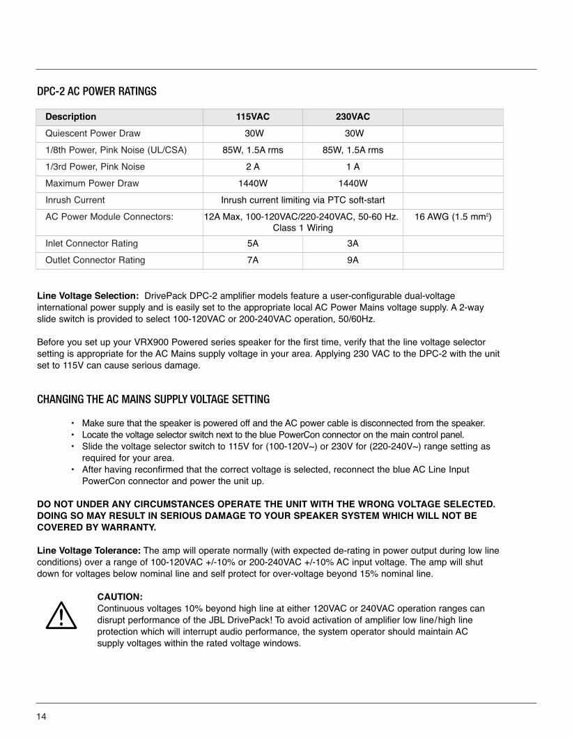
Description 115VAC 230VAC
Quiescent Power Draw 30W 30W
1/8th Power, Pink Noise (UL/CSA) 85W, 1.5A rms 85W, 1.5A rms
1/3rd Power, Pink Noise 2 A 1 A
Maximum Power Draw 1440W 1440W
Inrush Current Inrush current limiting via PTC soft-start
AC Power Module Connectors: 12A Max, 100-120VAC/220-240VAC, 50-60 Hz. Class 1 Wiring
16 AWG (1.5 mm2)
Inlet Connector Rating 5A 3A
Outlet Connector Rating 7A 9A
VRX_Powered_UsersGuid012808 copy 3.qxp 1/30/08 4:52 PM Page 14
INDICATORS
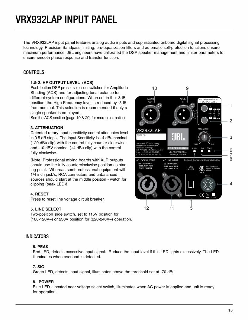
6. PEAK Red LED, detects excessive input signal. Reduce the input level if this LED lights excessively. The LED illuminates when overload is detected.
7. SIG Green LED, detects input signal, illuminates above the threshold set at -70 dBu.
8. POWER Blue LED - located near voltage select switch, illuminates when AC power is applied and unit is ready for operation.
VRX932LAP INPUT PANEL
The VRX932LAP input panel features analog audio inputs and sophisticated onboard digital signal processingtechnology. Precision Bandpass limiting, pre-equalization filters and automatic self-protection functions ensuremaximum performance. JBL engineers have calibrated the DSP speaker management and limiter parameters toensure smooth phase response and transfer function.
CONTROLS
1.& 2. HF OUTPUT LEVEL (ACS)Push-button DSP preset selection switches for Amplitude Shading (ACS) and for adjusting tonal balance for different system configurations. When set in the -3dB position, the High Frequency level is reduced by -3dB from nominal. This selection is recommended if only a single speaker is employed. See the ACS section (page 19 & 20) for more information.
3. ATTENUATION Detented rotary input sensitivity control attenuates level in 0.5 dB steps. The Input Sensitivity is +4 dBu nominal(+20 dBu clip) with the control fully counter clockwise, and -10 dBV nominal (+4 dBu clip) with the control fully clockwise.
(Note: Professional mixing boards with XLR outputs should use the fully counterclockwise position as starting point. Whereas semi-professional equipment with 1/4 inch jack’s, RCA connectors and unbalanced sources should start at the middle position - watch for clipping (peak LED)!
4. RESET Press to reset line voltage circuit breaker.
5. LINE SELECT Two-position slide switch, set to 115V position for (100-120V~) or 230V position for (220-240V~) operation.
1
2
3
678
4
51112
910
15
VRX_Powered_UsersGuid012808 copy 3.qxp 1/30/08 4:52 PM Page 15
16
CONNECTORS
9. Audio In F-XLR Active 20K Ohm Balanced, 10K Ohm Unbalanced. Pin 2 Hot (Positive voltage produces outward cone motion of L.F. Transducers).
10. Audio Out M-XLR Passive Audio Pass-through. Pin 2 Hot (Positive voltage produces outward cone motion of L.F. Transducers).
11. AC LINE INPUT Blue Neutrik PowerCon® NAC3MPA A-type airtight twist-lock chassis connector for AC power inlet. The mating blue cable connector is keyed and will insert in only one orientation. Electrical connection is made when the AC plug is fully inserted and twisted clockwise until locked into position.
12. LOOP OUTPUT Gray Neutrik PowerCon NAC3MPB B-type air tight twist-lock power outlet connector is provided to loop AC power through to additional units. The mating gray outlet cable connector is keyed and will insert in only oneorientation. Electrical connection is made upon fully inserting the AC plug and twisting clockwise until lockedinto position. To accomplish loop-thru AC power connections, simply attach a PowerCon jumper cable from the gray connector of the first loudspeaker system to the blue connector of the second, etc. Blue Inlet and Gray Outlet connectors are not interchangeable.
CAUTION:Looping more than three DPC-2 systems together is not recommended! Do not exceed 80%current rating of any AC connector at any time! Refer to AC Power Rating Tables in this document for current draw information.
VRX_Powered_UsersGuid012808 copy 3.qxp 1/30/08 4:52 PM Page 16
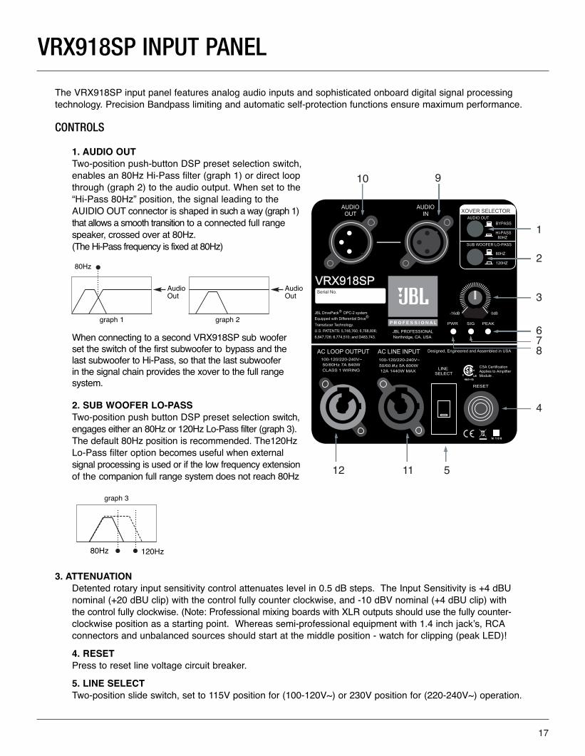
The VRX918SP input panel features analog audio inputs and sophisticated onboard digital signal processingtechnology. Precision Bandpass limiting and automatic self-protection functions ensure maximum performance.
CONTROLS
1. AUDIO OUTTwo-position push-button DSP preset selection switch, enables an 80Hz Hi-Pass filter (graph 1) or direct loop through (graph 2) to the audio output. When set to the“Hi-Pass 80Hz” position, the signal leading to the AUIDIO OUT connector is shaped in such a way (graph 1)that allows a smooth transition to a connected full range speaker, crossed over at 80Hz. (The Hi-Pass frequency is fixed at 80Hz)
When connecting to a second VRX918SP sub woofer set the switch of the first subwoofer to bypass and the last subwoofer to Hi-Pass, so that the last subwoofer in the signal chain provides the xover to the full range system.
2. SUB WOOFER LO-PASS Two-position push button DSP preset selection switch,engages either an 80Hz or 120Hz Lo-Pass filter (graph 3).The default 80Hz position is recommended. The120HzLo-Pass filter option becomes useful when external signal processing is used or if the low frequency extensionof the companion full range system does not reach 80Hz
3. ATTENUATIONDetented rotary input sensitivity control attenuates level in 0.5 dB steps. The Input Sensitivity is +4 dBU nominal (+20 dBU clip) with the control fully counter clockwise, and -10 dBV nominal (+4 dBU clip) with the control fully clockwise. (Note: Professional mixing boards with XLR outputs should use the fully counter-clockwise position as a starting point. Whereas semi-professional equipment with 1.4 inch jack’s, RCAconnectors and unbalanced sources should start at the middle position - watch for clipping (peak LED)!
4. RESET Press to reset line voltage circuit breaker.
5. LINE SELECT Two-position slide switch, set to 115V position for (100-120V~) or 230V position for (220-240V~) operation.
1
2
3
678
4
51112
910
VRX918SP INPUT PANEL
graph 1
graph 3
17
80Hz
80Hz 120Hz
graph 2
Audio Out
Audio Out
VRX_Powered_UsersGuid012808 copy 3.qxp 1/30/08 4:52 PM Page 17
18
INDICATORS 6. PEAK Red LED, detects excessive input signal. The LED illuminates when overload at any point is detected.
7. SIG Green LED, detects input signal, illuminates above the threshold set at -70 dBu.
8. POWER Blue LED - located near voltage select switch, illuminates when AC power is applied and unit is ready for operation.
CONNECTORS
9. Audio In F-XLR Active 20K Ohm Balanced, 10K Ohm Unbalanced. Pin 2 Hot (Positive voltage produces outward cone motion of L.F. Transducers).
10. Audio Out M-XLR Passive Audio Pass-through. Pin 2 Hot (Positive voltage produces outward cone motion of L.F. Transducers).
11. AC LINE INPUT Blue Neutrik PowerCon® NAC3MPA A-type air tight twist-lock chassis connector for AC power inlet. The mating blue cable connector is keyed and will insert in only one orientation. Electrical connection is made when the AC plug is fully inserted and twisted clockwise until locked into position.
12. AC LOOP OUTPUT Gray Neutrik PowerCon NAC3MPB B-type air tight twist-lock power outlet connector is provided to loop AC power through to additional units.
The mating gray outlet cable connector is keyed and will insert in only one orientation. Electrical connection is made upon fully inserting the AC plug and twisting clockwise until locked into position.
To accomplish loop-thru AC power connections, simply attach a PowerCon jumper cable from the gray connector of the first loudspeaker system to the blue connector of the second, etc. Blue Inlet and Gray Outlet connectors are not interchangeable.
CAUTION:Looping more than three DPC-2 systems together is not recommended! Do not exceed 80%current rating of any AC connector at any time! Refer to AC Power Rating Tables in this docu-ment for current draw information.
AUDIO SIGNAL DISTRIBUTION
Connecting source audio signals to the input modules on JBL DrivePack systems is similar to daisy-chainingmultiple external amplifier channels together.
Assuming an output device source impedance of 100 Ohms and a 10:1 load to source ratio, up to 20 JBLDrivePack units typical can be linked together on one output source without using a distribution amp.
VRX_Powered_UsersGuid012808 copy 3.qxp 1/30/08 4:52 PM Page 18
AMPLITUDE SHADING
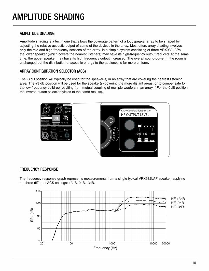
AMPLITUDE SHADING
Amplitude shading is a technique that allows the coverage pattern of a loudspeaker array to be shaped byadjusting the relative acoustic output of some of the devices in the array. Most often, array shading involves only the mid and high-frequency sections of the array. In a simple system consisting of three VRX932LAPs, the lower speaker (which covers the nearest listeners) may have its high-frequency output reduced. At the sametime, the upper speaker may have its high frequency output increased. The overall sound-power in the room isunchanged but the distribution of acoustic energy to the audience is far more uniform.
ARRAY CONFIGURATION SELECTOR (ACS)
The -3 dB position will typically be used for the speaker(s) in an array that are covering the nearest listeningarea. The +3 dB position will be used for the speaker(s) covering the more distant areas; or to compensate forthe low-frequency build-up resulting from mutual coupling of multiple woofers in an array. ( For the 0dB positionthe inverse button selection yields to the same results).
FREQUENCY RESPONSE
The frequency response graph represents measurements from a single typical VRX932LAP speaker, applyingthe three different ACS settings: +3dB, 0dB, -3dB.
19
VRX_Powered_UsersGuid012808 copy 3.qxp 1/30/08 4:52 PM Page 19
20
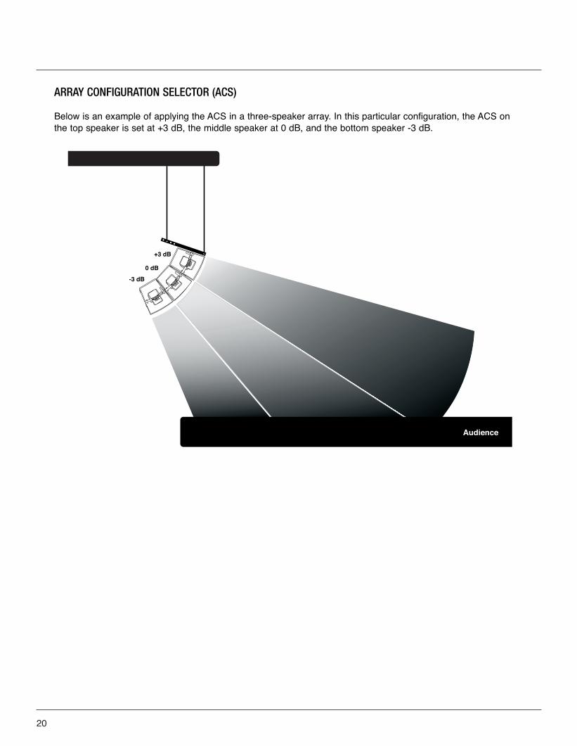
ARRAY CONFIGURATION SELECTOR (ACS)
Below is an example of applying the ACS in a three-speaker array. In this particular configuration, the ACS onthe top speaker is set at +3 dB, the middle speaker at 0 dB, and the bottom speaker -3 dB.
VRX_Powered_UsersGuid012808 copy 3.qxp 1/30/08 4:52 PM Page 20
SECTION 6: DEPLOYING THE SYSTEM
The VRX932LAP/VRX918SP are flexible speaker systems that can be deployed in ground-supported or suspended applications. The following information will help you set up your VRX932LAP/VRX918SP system safely and effectively.
POLE AND TRIPOD SAFETY WARNINGS!
When using stands or poles, be sure to observe the following precautions:
• Check the stand or pole specification to be certain the device is designed to support the weight of
the speaker. Observe all safety precautions specified by the manufacturer.
• Be certain that the surface on which the system is to be stacked is flat, stable and solid.
• Route cables so that performers, production crew, and audience will not trip and topple the speakers.
• Inspect the stand (or pole and associated hardware) before each use and do not use equipment with
worn, damaged, or missing parts.
• Do not attempt to place more than two VRX932LAP loudspeakers on a stand or pole.
• When mounting two VRX932LAP speakers on a pole or tripod, integral rigging hardware
must be used to secure the speakers to each other.
• Always be cautious when deploying the system outdoors. Unexpected winds may topple a system.
It may be necessary to place additional weight (i.e. sandbags) on the base of the stand to improve
stability. Avoid attaching banners or similar items to any part of a speaker system. Such attachments
could act as a sail and topple the system.
• Unless you are confident that you can handle the weight of the speaker, ask another person to help
you get it onto the tripod stand or pole.
• One or two VRX932LAP cabinets may be mounted onto either a JBL SS2-BK tripod stand or with
the SS4-BK adjustable pole mount to their companion VRX918SP subwoofers. Do not mount
VRX932LAP cabinets on top of the compact VRX915S subwoofer!
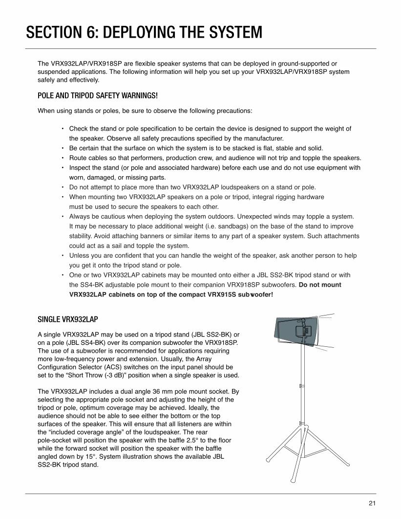
SINGLE VRX932LAP
A single VRX932LAP may be used on a tripod stand (JBL SS2-BK) oron a pole (JBL SS4-BK) over its companion subwoofer the VRX918SP.The use of a subwoofer is recommended for applications requiringmore low-frequency power and extension. Usually, the ArrayConfiguration Selector (ACS) switches on the input panel should beset to the “Short Throw (-3 dB)” position when a single speaker is used.
The VRX932LAP includes a dual angle 36 mm pole mount socket. Byselecting the appropriate pole socket and adjusting the height of thetripod or pole, optimum coverage may be achieved. Ideally, the audience should not be able to see either the bottom or the top surfaces of the speaker. This will ensure that all listeners are withinthe “included coverage angle” of the loudspeaker. The rear pole-socket will position the speaker with the baffle 2.5° to the floorwhile the forward socket will position the speaker with the baffleangled down by 15°. System illustration shows the available JBLSS2-BK tripod stand.
21
VRX_Powered_UsersGuid012808 copy 3.qxp 1/30/08 4:52 PM Page 21
22
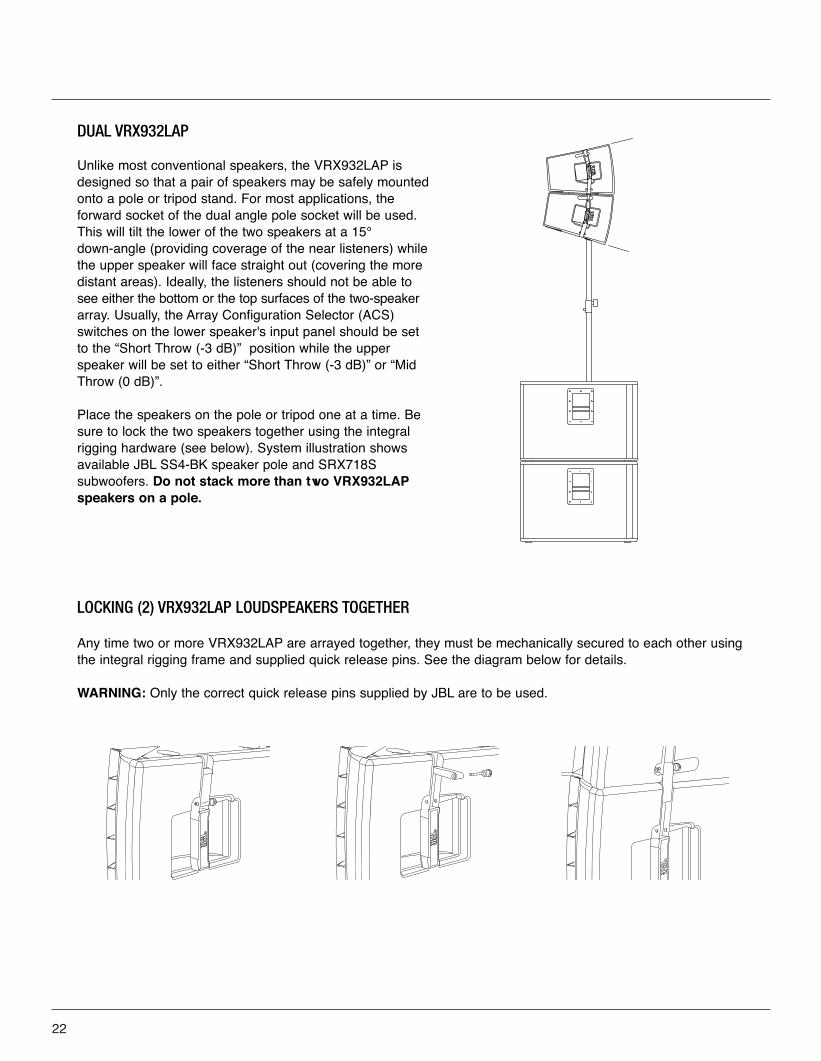
DUAL VRX932LAP
Unlike most conventional speakers, the VRX932LAP isdesigned so that a pair of speakers may be safely mountedonto a pole or tripod stand. For most applications, the forward socket of the dual angle pole socket will be used.This will tilt the lower of the two speakers at a 15°down-angle (providing coverage of the near listeners) whilethe upper speaker will face straight out (covering the moredistant areas). Ideally, the listeners should not be able tosee either the bottom or the top surfaces of the two-speakerarray. Usually, the Array Configuration Selector (ACS)switches on the lower speaker's input panel should be setto the “Short Throw (-3 dB)” position while the upperspeaker will be set to either “Short Throw (-3 dB)” or “MidThrow (0 dB)”.
Place the speakers on the pole or tripod one at a time. Besure to lock the two speakers together using the integralrigging hardware (see below). System illustration showsavailable JBL SS4-BK speaker pole and SRX718S subwoofers. Do not stack more than two VRX932LAPspeakers on a pole.
LOCKING (2) VRX932LAP LOUDSPEAKERS TOGETHER
Any time two or more VRX932LAP are arrayed together, they must be mechanically secured to each other usingthe integral rigging frame and supplied quick release pins. See the diagram below for details.
WARNING: Only the correct quick release pins supplied by JBL are to be used.
VRX_Powered_UsersGuid012808 copy 3.qxp 1/30/08 4:52 PM Page 22
Correct use of all rigging hardware is required for secure system suspension. Careful calculations should always be performed to ensure that all components are used within their Maximum Load Limit before the array is suspended. Never exceed the maximum recommended load ratings. Prior to suspending the system, an expert, trained and experienced in flying speaker systems should be consulted. Research and understandthe codes, practices, and requirements in the venues where you intend to operate your sound system.
INSPECTION & MAINTENANCE
Before suspending or pole mounting any speaker system always inspect all components (enclosure, riggingframes, pins, eyebolts, track fittings, etc.) for cracks, deformations, corrosion, missing, loose or damaged parts that could reduce strength and safety of the array. Do not suspend or pole mount the speaker until theproper corrective action has been taken. Installed systems should be inspected at least annually. The inspectionshall include a visual survey of all corners and load bearing surfaces for signs of cracking, water damage, de-lamination, or any other condition that may decrease the strength of the loudspeaker enclosure. Accessoryrigging hardware provided with or for the JBL VRX932LAP or VRX918SP loudspeaker must be inspected forfatigue at least annually or as required by local ordinance. For all other hardware and fittings, refer to the hard-ware manufacturer's inspection and maintenance guidelines for process.
ARE YOU NEW TO RIGGING?
If you are new to rigging, you should do the following:
• Read and study JBL Technical Note Volume 1, Number 14: Basic Principles for Suspending Loudspeaker Systems (available at http://www.jblpro.com/pub/technote/tn_v1n14.pdf).
• Know the rules for safe rigging.• Attend a safe rigging seminar, such as that presented by professionals like Rigging Seminars™
(www.riggingseminars.com) or by Chain Motor Hoist manufacturers like Columbus McKinnon Corp. (manufacturers of the C/M Lodestar).
• Meet and establish a relationship with a licensed mechanical or structural engineer. Get in the habit of asking them questions instead of guessing about their answers. Learn from what they tell you.
• Meet and discuss this aspect of your business with your Insurance Agent.
ATTACHMENT TO STRUCTURES
A licensed Professional Engineer must approve the placement and method of attachment to the structure prior to the installation of any overhead object. The following performance standards should be provided to theProfessional Engineer for design purposes; Uniform Building Code as applicable, Municipal Building Code asapplicable, and Seismic Code as applicable. The installation of the hardware and method of attachment must be carried out in the manner specified by the Professional Engineer. Improper installation may result in damage, injury or death.
JBL is not responsible for the application of its products for any purpose or the misuse of this information for anypurpose. Furthermore, JBL is not responsible for the abuse of its products caused by avoiding compliance withinspection and maintenance procedures or any other abuse.
SECTION 7: SUSPENSION SAFETY WARNINGS!
23
VRX_Powered_UsersGuid012808 copy 3.qxp 1/30/08 4:52 PM Page 23

WARNING: Do not use the older VRX932LA-AF array frame to suspend powered VRX932LAP or VRX918SP systems
INSTALLING THE ARRAY FRAME
The array frame is attached to the internal rigging of the VRX900 system using the provided Quick Release PinsWARNING: Do not use any substitute for these pins.
1. Begin by attaching the two side arms (A) to either side of the center frame. Use a pair of the provided QuickRelease Pins (B) to attach the arms to the frame.
NOTE 1: Side arms should be attached with the rubber bumper facing up and away from the center frame. The center frame is installed with the rubber gasket toward the enclosure and the label right side up.
NOTE 2: The arms of the VRX932LA-AF and VRX-AF aredeliberately designed so as not to be interchangeable. The arms of the VRX-SMAF are already attached.
2. Place the entire array frame on top of the VRX900 systemand flip up the drop levers (C) found on both sides of thespeaker to be received by the array frame arms.
3. Once the drop levers on the speaker are received by the array frame, use a pair of the provided Quick Release Pins (D) to attach the drop levers to the array frame.
(C)
(A) (D)(B) (A)
(D)
MAXIMUM ARRAY SIZE
There are three variations of the VRX array frame. The VRX-AF supersedes the VRX932LA-AF. The VRX-SMAFis solely intended for use with the VRX928LA and VRX915S. Before suspending a VRX array, determine whichversion of the array frame you have and consult the table below to determine the maximum number of speakersthat may be safely suspended. The subwoofers must always be at the top of the array.
NOTE: For combination of passive and powered speaker systems use the table for powered speakers(VRX932LAP and VRX918SP).
VRX932LA-AF Array Frame
VRX-AF ARRAY FRAMEThe following table defines the maximum number of speakers that may be suspended using the VRX-AF frame.A minimum design factor of 7:1 is maintained for all speaker configurations at or below those indicated in the table.
Maximum number of VRX918SP in array 0 2 3 3 4 4
Maximum number of VRX932LAP in array 5 4 3 2 1 0
24
VRX_Powered_UsersGuid012808 copy 3.qxp 1/30/08 4:52 PM Page 24
25
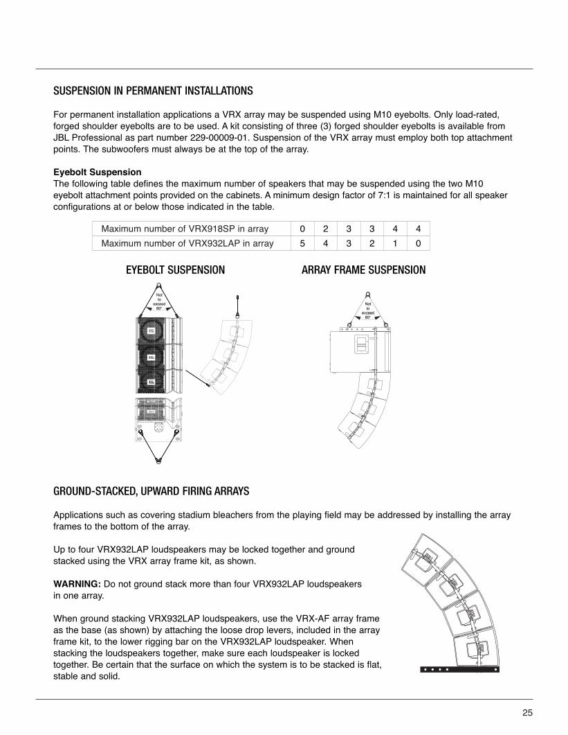
GROUND-STACKED, UPWARD FIRING ARRAYS
Applications such as covering stadium bleachers from the playing field may be addressed by installing the arrayframes to the bottom of the array.
Up to four VRX932LAP loudspeakers may be locked together and groundstacked using the VRX array frame kit, as shown.
WARNING: Do not ground stack more than four VRX932LAP loudspeakers in one array.
When ground stacking VRX932LAP loudspeakers, use the VRX-AF array frameas the base (as shown) by attaching the loose drop levers, included in the arrayframe kit, to the lower rigging bar on the VRX932LAP loudspeaker. Whenstacking the loudspeakers together, make sure each loudspeaker is lockedtogether. Be certain that the surface on which the system is to be stacked is flat,stable and solid.
SUSPENSION IN PERMANENT INSTALLATIONS
For permanent installation applications a VRX array may be suspended using M10 eyebolts. Only load-rated,forged shoulder eyebolts are to be used. A kit consisting of three (3) forged shoulder eyebolts is available fromJBL Professional as part number 229-00009-01. Suspension of the VRX array must employ both top attachmentpoints. The subwoofers must always be at the top of the array.
Eyebolt Suspension The following table defines the maximum number of speakers that may be suspended using the two M10 eyebolt attachment points provided on the cabinets. A minimum design factor of 7:1 is maintained for all speakerconfigurations at or below those indicated in the table.
EYEBOLT SUSPENSION ARRAY FRAME SUSPENSION
Maximum number of VRX918SP in array 0 2 3 3 4 4
Maximum number of VRX932LAP in array 5 4 3 2 1 0
VRX_Powered_UsersGuid012808 copy 3.qxp 1/30/08 4:52 PM Page 25
26
SECTION 8 : INTRODUCTION TO THE VRX-AF
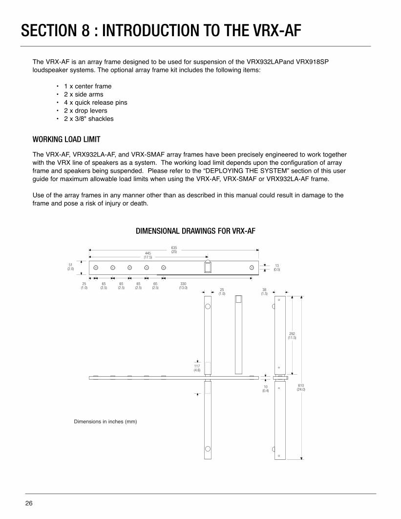
The VRX-AF is an array frame designed to be used for suspension of the VRX932LAPand VRX918SPloudspeaker systems. The optional array frame kit includes the following items:
• 1 x center frame• 2 x side arms• 4 x quick release pins• 2 x drop levers• 2 x 3/8" shackles
WORKING LOAD LIMIT
The VRX-AF, VRX932LA-AF, and VRX-SMAF array frames have been precisely engineered to work togetherwith the VRX line of speakers as a system. The working load limit depends upon the configuration of arrayframe and speakers being suspended. Please refer to the “DEPLOYING THE SYSTEM” section of this userguide for maximum allowable load limits when using the VRX-AF, VRX-SMAF or VRX932LA-AF frame.
Use of the array frames in any manner other than as described in this manual could result in damage to theframe and pose a risk of injury or death.
51(2.0)
25(1.0)
65(2.5)
65(2.5)
65(2.5)
65(2.5)
445(17.5)
635(25)
330(13.0)
13(0.5)
25(1.0)
38(1.5)
292(11.5)
117(4.6)
10(0.4)
610(24.0)
DIMENSIONAL DRAWINGS FOR VRX-AF
Dimensions in inches (mm)
VRX_Powered_UsersGuid012808 copy 3.qxp 1/30/08 4:52 PM Page 26
27
JBL WARRANTY AND INFORMATION
MAILING ADDRESS:JBL Professional8500 Balboa Blvd.Northridge, CA 91329 USA
SHIPPING ADDRESS:JBL Professional8370 Balboa Blvd., Dock DNorthridge, CA 91329 USA(Do not return product to this address withoutfirst obtaining prior authorization from JBL)
CUSTOMER SERVICE:Monday through Friday 8:00am - 5:00pm Pacific Standard Time In the U.S.A. (800) 8JBLPRO (800.852.5776)www.jblproservice.com
OUTSIDE THE USA:
Contact the JBL Professional Distributor in your area. Acomplete list of JBL Professional international distributors isprovided at our U.S.A.website - www.jblpro.com
PRODUCT REGISTRATION:
Register your product online at www.jblpro.com/registration
ON THE WORLD WIDE WEB:
www.jblpro.com
The JBL Warranty on professional loudspeaker products (except for enclosures) remains in effect for five years from the date of the first consumer purchase. JBL amplifiers are warranted for three years from the date of original purchase. Enclosures and all other JBL products are warranted for two years from the date of original purchase.
WHO IS PROTECTED BY THIS WARRANTY? Your JBL Warranty protects the original owner and all subsequent owners so long as: A.) Your JBL product has been purchased in the Continental United States, Hawaii or Alaska. (This Warranty does not apply to JBLproducts purchased elsewhere except for purchases by military outlets. Other purchasers should contact thelocal JBL distributor for warranty information.); and B.) The original dated bill of sale is presented whenever warranty service is required.
WHAT DOES THE JBL WARRANTY COVER? Except as specified below, your JBL Warranty covers all defects in material and workmanship. The following are not covered: Damage caused by accident, misuse, abuse, product modification or neglect; damage occurring during shipment; damage resulting from failure to follow instructions contained in your InstructionManual; damage resulting from the performance of repairs by someone not authorized by JBL; claims basedupon any misrepresentations by the seller; any JBL product on which the serial number has been defaced, modified or removed.
WHO PAYS FOR WHAT? JBL will pay all labor and material expenses for all repairs covered by this warranty. Please be sure to save the original shipping cartons because a charge will be made if replacement cartons are requested. Payment of shipping charges is discussed in the next section of this warranty.
HOW TO OBTAIN WARRANTY PERFORMANCEIf your JBL product ever needs service, write or telephone us at JBL Incorporated (Attn: Customer ServiceDepartment), 8500 Balboa Boulevard, PO Box 2200, Northridge, California 91329 (818-893-8411). We maydirect you to an authorized JBL Service Agency or ask you to send your unit to the factory for repair. Either way, you'll need to present the original bill of sale to establish the date of purchase. Please do not ship your JBL product to the factory without prior authorization. If transportation of your JBL product presents any unusualdifficulties, please advise us and we may make special arrangements with you. Otherwise, you are responsiblefor transporting your product for repair or arranging for its transportation and for payment of any initial shippingcharges. However, we will pay the return shipping charges if repairs are covered by the warranty.
VRX_Powered_UsersGuid012808 copy 3.qxp 1/30/08 4:52 PM Page 27
JBL Professional8500 Balboa Blvd.
Northridge, CA 91329 USAPart Number: 364536-001 09/2007
VRX_Powered_UsersGuid012808 copy 3.qxp 1/30/08 4:52 PM Page 28


![[JBL S3900] JBL 가문에서 출중한 미인이 탄생하다 - 월간오디오](https://img.pdfslide.net/doc/110x75/568c36b21a28ab0235990729/jbl-s3900-jbl-.jpg)