Embed Size (px)
Citation preview
1
USERS MANUAL FOR
PALMER STATION GPS SYSTEM
Version 2.0
May 2013
Prepared by:
Seth White and Thomas Nylen

2
TABLE OF CONTENTS
I. OVERVIEW
II. SURVEYING BASICS
A. Differential Surveying
B. Initialization: A Key Concept
C. Kinematic Surveying
1. PPK Surveys
2. RTK Surveys
III. EQUIPMENT
A. Base System
1. Base Receiver
2. RTK Base Radio
B. Roving System
1. Roving Receiver
2. Data Collector with Survey Controller Software
3. Bipod
4. Kinematic Backpack
5. RTK Repeater
6. Batteries
IV. PERFORMING A STATIC SURVEY
A. Verify Base Receiver Operation
B. Configure R7 receiver
C. Perform Static Occupation
V. PERFORMING A PPK SURVEY
A. Verify Base Receiver Operation
B. Set up Roving System
C. Program Roving Receiver
D. Measure Points and/or Contours
E. Download Base and Roving GPS Datafiles and Perform Data QC
F. Using the Bipod versus the Backpack Antenna Mount
VI. PERFORMING AN RTK SURVEY
A. Program Roving Receiver
B. Turn on Base Radio
C. Measure Points and/or Contours
D. Navigating to a Point
E. Download Roving GPS Datafiles and Perform Data QC F. RTK Repeater

3
VII. ADDITIONAL SYSTEM INFORMATION
A. Downloading Data from the NetR8 Base
B. Downloading Data from the TSC2 Data Collector
C. Downloading Data from the R7 Roving Receiver
D. Base Coordinates
E. Software
F. Quality Checking Data Using Trimble Business Center Software
4
I. OVERVIEW
The Palmer Station continuous GPS station PALM was installed by Larry Hothem
(USGS) in 1997. USGS also provided an RTK survey system.
In 2006, the UNAVCO Polar group provided a new GPS base receiver PAL2, connected
to the same GPS antenna as station PALM. A new survey system was also provided,
available for use by visiting science groups as well as station staff. This new equipment
was installed by Glenn Grant. This system provides two main functions:
- Real-time and post-processed survey capabilities for precision mapping
and positioning tasks
- Continuous GPS data recording for scientific purposes.
This system provides real-time centimeter-level positioning within the immediate camp
area (~5 km). With proper surveying techniques, high accuracies can also be achieved
within a ~100 km radius through post-processing of data.
This document is intended to provide enough information for the Palmer Station Science
Technician to operate the system at a nominal level. Normal Science Technician support
for the GPS system should consist of simple real-time and/or post-processed surveys as
requested, and basic troubleshooting and repair as needed. Although GPS training at the
UNAVCO office in Boulder, Colorado is recommended for incoming Science
Technicians when possible, the frequent Science Technician turnover will generally not
allow everyone to have more than a basic knowledge of the system. Therefore, when
more sophisticated surveying and measurement tasks are needed, the requesting science
group should contact UNAVCO in advance of the project for formal GPS training and/or
UNAVCO field engineer support.
A Palmer Station GPS webpage is maintained here, containing system specifications,
inventory, and other useful technical information.
http://facility.unavco.org/project_support/polar/palmer/palmer.html
For technical support, send email to: [email protected]
For more information on the Global Positioning System and how it works, see the
following online tutorials.
http://www.javad.com/ As of 2013 a GPS tutorial (PDF) was still accessible here.
http://www.kowoma.de/en/gps/history.htm
http://gps.faa.gov/ As of 2013 a GPS tutorial was accessible from main page.
5
II. SURVEYING BASICS
A. Differential Surveying
For high precision GPS surveying, the differential technique is used most frequently. The
simplest differential survey requires two receivers operating simultaneously: the
stationary (“base”) system and the moving (“roving”) system. The differential technique
takes advantage of the fact that many error sources which affect the accuracy of GPS
positions are “common mode” between the base and roving receivers. If the two systems
are located close enough to each other, these errors can be cancelled out in such a way
that allows the baseline distance between the antennas to be calculated very accurately.
As the systems move farther apart, more and more data must be taken to resolve the
baseline, up to a practical maximum of ~100 km.
During surveying the base system, or more precisely the base antenna, is positioned at a
precisely-known coordinate. Then the roving receiver collects data while its antenna is
positioned at the point(s) of interest. To generate accurate coordinates for points surveyed
by the roving system, the “baseline” distance between the base and roving antennas is
calculated for each point, then added vectorially to the base coordinate. Thus the
accuracy of coordinates measured by the roving system is obtained by a) very accurate
knowledge of the base antenna coordinates and b) very precise baselines between the
base and roving antennas.
An accurate base coordinate can be obtained in three ways. First, the base antenna can be
positioned over a previously surveyed marker if such markers exist near the survey site.
Second, if there is a GPS reference station operating nearby, a baseline can be generated
from the reference station to your base station, thereby providing a good 3-D coordinate
for your base. Finally if no markers or reference stations are within a reasonable distance
of the survey area, your base coordinate can be generated by recording a long GPS data
file (e.g. 24 hours) and then using precise point positioning (PPP) techniques to arrive at
an accurate “autonomous” base coordinate.
Once the base has been established, the precision of baselines between base and rover is
achieved by good survey techniques. Such techniques include keeping the roving GPS
antenna level and providing it with an unobstructed sky view. Power to the roving
receiver must be maintained, along with a good “initialization”, as described below.
B. Initialization: A Key Concept
For several reasons, accurate baselines cannot be generated instantly. Satellite data must
be collected simultaneously by both base and rover for a certain period of time before an
accurate baseline can be unambiguously solved for. This period of time is the
“initialization” period, and varies depending on the baseline distance between base and
rover, the number of satellites in view, and other factors. However, once an initialization
is gained, that initialization applies to all points surveyed thereafter until either a)
initialization is lost or b) the survey is ended. In addition, this initialization also applies
6
backward in time, as long as satellite tracking was maintained during that time (while
initialization was being gained).
If initialization is lost, the points surveyed while the system was initialized are still valid.
However, surveying new points requires that a new initialization must be gained. This
new initialization will require as much time as the first initialization. Initialization can be
lost in several ways, for example if the roving antenna’s view of the sky is obstructed by
a building wall, if the antenna is tilted far away from level, if the antenna cable becomes
detached, or if the roving (or base) receiver loses power.
C. Kinematic Surveying
At Palmer Station, it is anticipated that most if not all usage of the GPS system will be
“kinematic” surveying. As opposed to “static” surveying, where a GPS system is installed
at one location for a long period of time (for example to measure the position of one point
very accurately, or to measure motion of slow-moving features such as glaciers or
tectonic plates), kinematic surveying essentially refers to mapping operations. A
kinematic survey can involve both “topo points”, where the surveyor stops at specific
points and measures their locations, and “continuous topo” segments, where the surveyor
moves along a certain path and the receiver tracks the movement.
For example, if a new building was added at Palmer, the station layout drawing could be
updated by surveying the four corners of the building (topo points) and then walking
along the path of the building’s main power and/or water lines (continuous topo).
Another example would be mounting the roving system on a Zodiac and measuring the
shorelines of nearby islands (continuous topo) and locations of survival caches (topo
points). There are two main types of kinematic surveys: post-processed kinematic (PPK)
or real time kinematic (RTK).
1. PPK Surveys
With post-processed surveys, there is no communication between the base and
roving receivers. GPS processing software is required to combine data from the
base and roving receivers, after the survey, to obtain the results. Thus, baseline
solutions for surveyed points cannot be generated until after the survey is
complete. Coordinates can then be exported for use in GIS, plotting, or drawing
software. Two main advantages of a PPK survey over an RTK survey are:
- Longer baselines can be measured, up to 50-100 km from the base. RTK is
limited to approximately 5 km baselines.
- There are fewer pieces of equipment to operate, since there is no radio link
required between the base and roving receivers.
7
2. RTK Surveys
An RTK system allows the surveyor to obtain precise coordinate solutions as the
survey is being conducted. This is accomplished using a radio link between the
base and roving receivers, where the base receiver broadcasts a data stream which
allows the roving system to calculate precise baselines between base and rover in
real time. Since the base station also broadcasts its own position, the baselines can
be used to calculate the precise position of the roving system. Two main
advantages of RTK surveys are:
- Instantaneous display of precise coordinates. This is particularly useful if
the surveyor wishes to find an exact coordinate, such as a previously
surveyed mark that has since been buried in snow. RTK can do this
whereas PPK can not.
- An RTK system will tell the user when it is initialized. With a PPK
system, you need to acquire a conservative amount of data to ensure your
post-processing will yield a good initialization.
8
III. EQUIPMENT
A. Base System
1. Base receiver
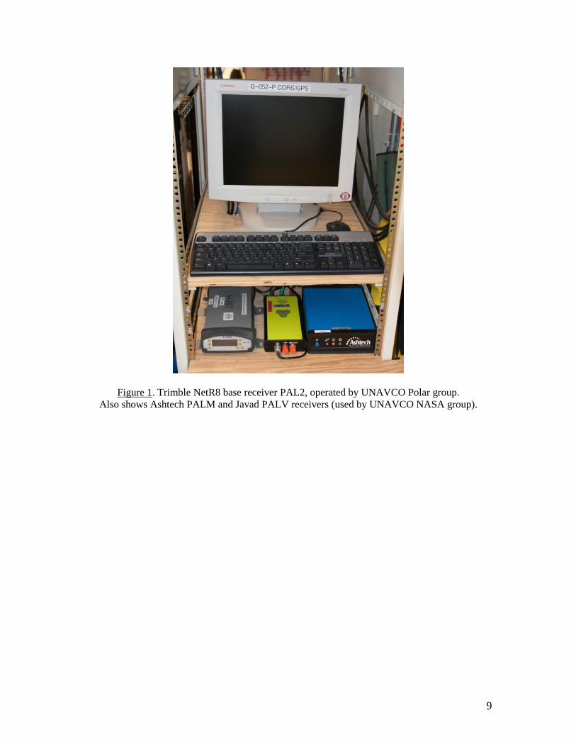
Base receiver PAL2 is a Trimble NetR8, located in the TerraLab building in the
back of the shelf below the G-052 computer monitor (Figure 1). The base antenna
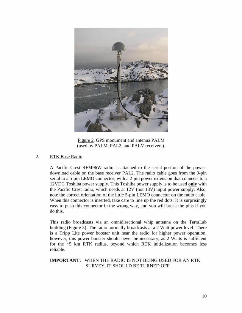
is an Ashtec Dorne Margolin Choke Ring, mounted on a mast on bedrock near
the shoreline (Figure 2). There is a self-powered antenna splitter which divides
the signal between the original PALM receiver and backup PALV receivers
(Ashtech and Javad, maintained by the UNAVCO NASA group) and the PAL2
receiver (Trimble, maintained by the UNAVCO Polar group).
The NetR8 is powered by an 18VDC power supply, which plugs into the receiver
via a “power/download” cable. This cable is a Y-cable, with coaxial power, 9-pin
serial, and 7-pin LEMO connectors. The serial portion of this cable goes to the
RTK radio, see below.
Also connected to the receiver is a straight ethernet cable which plugs into a local
router. The base receiver should always be turned on, since it is continuously
collecting data even when there is no survey underway. This continuous data has
scientific applications and is automatically downloaded by UNAVCO each day.
The NetR8 receiver has HTML, FTP, and SSH interfaces for programming and
data retrieval. A read-only account has been set up for Palmer Station users to
retrieve data through the local network (see section VII.A). All programming and
configuration are done remotely by UNAVCO, using a separate access account.
The receiver has 4GB of memory operating in ring-buffer mode, and it is
partitioned for recording high-rate and low-rate GPS data. The low rate data is
recorded every 15 seconds, and a new low-rate data file is created at the start of
each UTC day. The high rate data (currently set to 2Hz and 10Hz logging) is
recorded to hourly files. UNAVCO automatically downloads and archives the 15-
second data year-round, with 2Hz data downloaded and archived only during each
austral summer season (October-February). Due to the large file sizes, the 10Hz
data is only downloaded upon request.
The Trimble NetR8 receiver has an internal 8V lithium battery, which acts as a
UPS. This battery will power the receiver for ~8 hours in the event that AC power
is lost.
9
Figure 1. Trimble NetR8 base receiver PAL2, operated by UNAVCO Polar group.
Also shows Ashtech PALM and Javad PALV receivers (used by UNAVCO NASA group).
10
Figure 2. GPS monument and antenna PALM
(used by PALM, PAL2, and PALV receivers).
2. RTK Base Radio
A Pacific Crest RFM96W radio is attached to the serial portion of the power-
download cable on the base receiver PAL2. The radio cable goes from the 9-pin
serial to a 5-pin LEMO connector, with a 2-pin power extension that connects to a
12VDC Toshiba power supply. This Toshiba power supply is to be used only with
the Pacific Crest radio, which needs at 12V (not 18V) input power supply. Also,
note the correct orientation of the little 5-pin LEMO connector on the radio cable.
When this connector is inserted, take care to line up the red dots. It is surprisingly
easy to push this connector in the wrong way, and you will break the pins if you
do this.
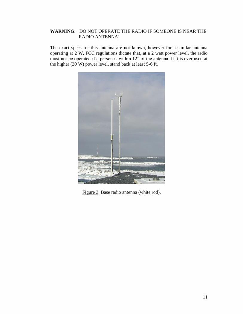
This radio broadcasts via an omnidirectional whip antenna on the TerraLab
building (Figure 3). The radio normally broadcasts at a 2 Watt power level. There
is a Tripp Lite power booster unit near the radio for higher power operation,
however, this power booster should never be necessary, as 2 Watts is sufficient
for the ~5 km RTK radius, beyond which RTK initialization becomes less
reliable.
IMPORTANT: WHEN THE RADIO IS NOT BEING USED FOR AN RTK
SURVEY, IT SHOULD BE TURNED OFF.
11
WARNING: DO NOT OPERATE THE RADIO IF SOMEONE IS NEAR THE
RADIO ANTENNA!
The exact specs for this antenna are not known, however for a similar antenna
operating at 2 W, FCC regulations dictate that, at a 2 watt power level, the radio
must not be operated if a person is within 12” of the antenna. If it is ever used at
the higher (30 W) power level, stand back at least 5-6 ft.
Figure 3. Base radio antenna (white rod).
12
B. Roving System
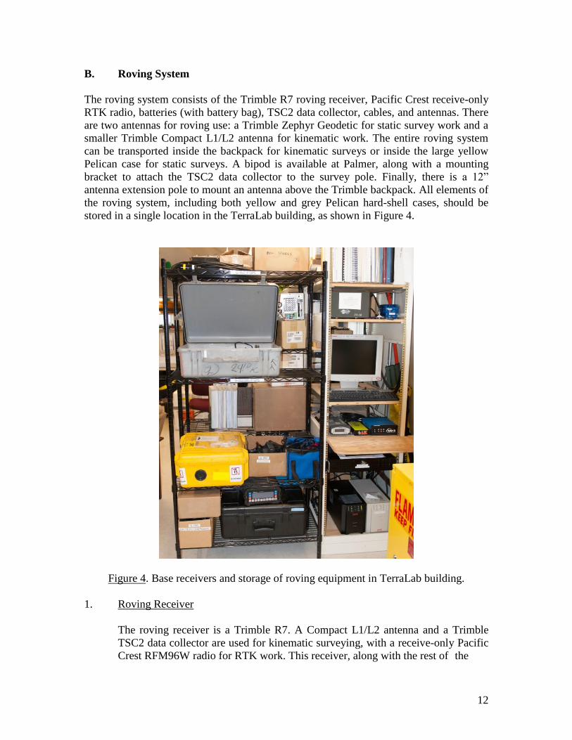
The roving system consists of the Trimble R7 roving receiver, Pacific Crest receive-only
RTK radio, batteries (with battery bag), TSC2 data collector, cables, and antennas. There
are two antennas for roving use: a Trimble Zephyr Geodetic for static survey work and a
smaller Trimble Compact L1/L2 antenna for kinematic work. The entire roving system
can be transported inside the backpack for kinematic surveys or inside the large yellow
Pelican case for static surveys. A bipod is available at Palmer, along with a mounting
bracket to attach the TSC2 data collector to the survey pole. Finally, there is a 12”
antenna extension pole to mount an antenna above the Trimble backpack. All elements of
the roving system, including both yellow and grey Pelican hard-shell cases, should be
stored in a single location in the TerraLab building, as shown in Figure 4.
Figure 4. Base receivers and storage of roving equipment in TerraLab building.
1. Roving Receiver
The roving receiver is a Trimble R7. A Compact L1/L2 antenna and a Trimble
TSC2 data collector are used for kinematic surveying, with a receive-only Pacific
Crest RFM96W radio for RTK work. This receiver, along with the rest of the
13
roving system hardware, should be stored in the yellow and/or grey Pelican cases.
An inventory is maintained online at the Palmer Station support pages here:
http://facility.unavco.org/project_support/polar/palmer/palmer.html
2. Data Collector with Survey Controller Software
The Trimble TSC2 data collector is used for kinematic work, both real-time and
post-processed. This primary purpose of this device is to run the Trimble Survey
Controller software. The data collector connects to the roving receiver and
performs several functions:
- It communicates with the receiver and gives the user full control of
receiver configuration, superceding any programs that may be stored in the
receiver.
- It displays critical information about the current survey, including satellite
tracking data, battery power levels, receiver configuration, and points contained in
the current survey job. In an RTK survey, it also displays radio information, real-
time coordinates with calculated baseline precisions, and initialization
information.
- It allows the user to give names to measured points and contours.
3. Bipod
A 2-meter bipod is available for higher-accuracy survey tasks. It provides a more
stable and accurate platform for the antenna than the backpack-mounted
arrangement. A built-in bubble level allows the antenna to be positioned
vertically, directly above the point to be measured. It also has two telescoping
feet to stabilize the antenna during the actual measurement of the point. A bracket
is also provided to attach the TSCe to the bipod for ease of operation during
surveying.
The survey pole can also be used as a monopod, without the bipod brackets
attached.
4. Kinematic Backpack
This backpack can be used to house the receiver, battery, and RTK radio during
field surveys, leaving hands free to operate the TSC2 data collector (and
bipod/survey pole if used). Also, for lower accuracy surveys the roving antenna
can actually be mounted on a 12” extension pole which attaches to the top of the
backpack. This 12” pole should be stored in the backpack when not in use.
14
5. RTK Repeater
An RTK repeater radio system is available at Palmer for surveys which are within
the range of RTK solutions (~5 km) but beyond a direct line of sight to the RTK
broadcast antenna. This radio (with whip antenna) will rebroadcast the signal
from the base RTK radio.
6. Batteries
Two Powersonic 18 amp-hour external batteries are available for surveying. Each
battery should last ~24 hours in the cold when fully charged. These batteries are
charged using any 12 VDC battery charger suitable for sealed lead-acid type
batteries.
The TSCe has its own internal battery, which can be charged using a
power/download cable and the spare Friwo 18VDC AC adapter. During
surveying, however, the TSCe takes power from the external battery (through the
R7 receiver) and only uses its internal battery if the external power source is lost.
Two larger batteries are also available, 31 amp-hour and a 40 amp-hour cells.
These can be used for longer duration kinematic surveys, or to power the RTK
repeater radio.
15
IV. PERFORMING A STATIC SURVEY
At Palmer, static surveys using this system will be very infrequent. Static surveys are
done to measure positions with extreme accuracy, or to track motions of features (e.g.
glaciers) over time. Static occupations are generally long in duration, from hours to
months, and it is anticipated that any science project wishing to perform static surveying
will contact UNAVCO directly and request suitable equipment for the job prior to the
field season. However, instructions are provided here in the unlikely event that the
Science Technician is required to perform a static survey.
A. Verify Base Receiver Operation
To ensure the base is operating correctly, it is sufficient to look at the front panel of the
NetR8 receiver. To illuminate the display, press any button. The top left of the display
should say “SV X”, where X is the number of satellite vehicles being tracked (usually
more than 7). The bottom left should alternate between Logging and Ref Stn. The top
right will show a battery icon, indicating the status of the NetR8’s internal battery UPS.
Since the receiver is powered by 18VDC the internal battery should always be fully
charged, therefore this battery icon will be solid green.
If any of these indicators are different than above and the problem is not readily apparent,
i.e. disconnected cables, contact UNAVCO.
B. Configure R7 Receiver
For static surveys, the R7 receiver must be configured directly since the TSC2 data
collector is not used. For such surveys, it should be sufficient to simply load the default
configuration file. You may elect to change the antenna information in the config file, but
this is not critical since this can be changed during post-processing. The default
configuration file for the Trimble R7 is located on the TerraLab Office PC, and is named
R7_24hr_15sec_Static_withRTK.cfg
Programming the R7 correctly is critical for collecting the desired data. The process is
not difficult, however a well understood sequence must be followed to ensure proper data
collection. To program the R7 for static occupations, use the following steps:
1. Using a power/download cable, connect Port 2 on the R7 to the TerraLab Office
PC (or any other computer with Trimble Configuration Toolbox loaded). The
Keyspan USB-serial adapter can be used if the computer does not have a 9-pin
serial port. Use the spare Friwo 18V AC adapter to power the R7 through the
power/download cable.
The 7-pin LEMO connector on the power/download cable can easily be inserted
the wrong way, causing breakage of the pins. The correct way to use this
connector is:
16
a. Align the red dot on the plug with the red mark on the jack. This ensures
that the key on the plug will slide into the slot on the jack.
b. Push firmly but do not force the connector. If resistance is felt, remove
the connector and check for debris inside and/or crooked pins. Realign the
connector and reinsert.
c. Give a slight tug on the cable itself to make sure the connector doesn’t pull
out. If properly connected, a mechanism will lock the connector in place to
prevent the cable from inadvertently detaching if the cable is pulled.
d. To remove the cable, pull the wire loop attached to the housing. This
action retracts the two small “ears” and allows the cable to slide out.
2. Perform a hard reset of the R7 by holding down the power button for 45 seconds.
After 15 seconds, the red satellite tracking LED will come on. After 30 seconds it
will turn off. CAUTION: The hard reset will format the compact flash card
and erase all data on the card! If there is any important data on the flash card,
be sure to download it first. You can also remove the flash card before doing the
hard reset.
3. Start the Trimble Configuration Toolbox program and “Open” the UNAVCO
default configuration file, R7_24hr_15sec_Static_withRTK.cfg (see above). This
configuration file specifies 15-second data logging, and creates one new file each
day. It is unlikely that any settings will need to be changed (other than the
Antenna settings as described below), but if so, now is the time to do it.
4. If you want to change the antenna settings, select “Antenna” from the “Contents:”
window. Again, this is not critical since you can modify these values during post-
processing. For static work, use the Zephyr Geodetic antenna. Select
“Zephyr Geodetic” under the “Type” box. You can also modify the antenna
height under the “Method” box. This height is almost always referenced to
“Bottom of antenna mount”. For example, if you set up using the bipod and the
bottom of the Zephyr Geodetic is measured at 2.000m above the point of interest,
enter “2.000m” and reference to “Bottom of antenna mount”. Once you have
changed the antenna height, click “Transmit”. You should get a window which
says the file was successfully uploaded to the receiver.
IMPORTANT: Configuration Toolbox Bug. If you make any changes to the
configuration file and want to save the modified file to your hard drive, be
sure to “Transmit” the file to the receiver before “Saving” it. If you “Save”
then “Transmit”, the receiver will NOT automatically log data (you do not
want this!)
17
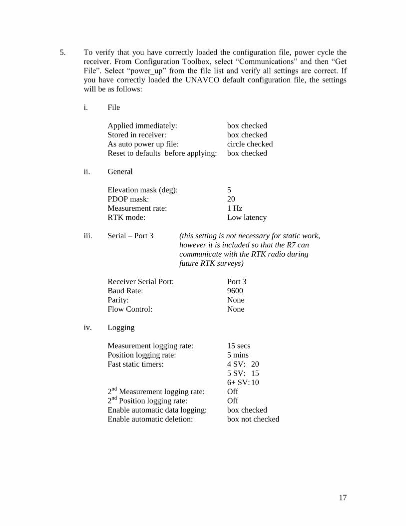
5. To verify that you have correctly loaded the configuration file, power cycle the
receiver. From Configuration Toolbox, select “Communications” and then “Get
File”. Select “power_up” from the file list and verify all settings are correct. If
you have correctly loaded the UNAVCO default configuration file, the settings
will be as follows:
i. File
Applied immediately: box checked
Stored in receiver: box checked
As auto power up file: circle checked
Reset to defaults before applying: box checked
ii. General
Elevation mask (deg): 5
PDOP mask: 20
Measurement rate: 1 Hz
RTK mode: Low latency
iii. Serial – Port 3 (this setting is not necessary for static work,
however it is included so that the R7 can
communicate with the RTK radio during
future RTK surveys)
Receiver Serial Port: Port 3
Baud Rate: 9600
Parity: None
Flow Control: None
iv. Logging
Measurement logging rate: 15 secs
Position logging rate: 5 mins
Fast static timers: 4 SV: 20
5 SV: 15
6+ SV: 10
2nd
Measurement logging rate: Off
2nd
Position logging rate: Off
Enable automatic data logging: box checked
Enable automatic deletion: box not checked
18
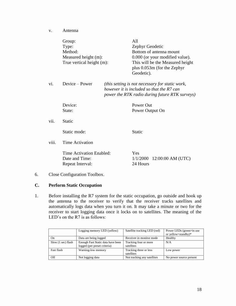
v. Antenna
Group: All
Type: Zephyr Geodetic
Method: Bottom of antenna mount
Measured height (m): 0.000 (or your modified value).
True vertical height (m): This will be the Measured height
plus 0.053m (for the Zephyr
Geodetic).
vi. Device – Power (this setting is not necessary for static work,
however it is included so that the R7 can
power the RTK radio during future RTK surveys)
Device: Power Out
State: Power Output On
vii. Static
Static mode: Static
viii. Time Activation
Time Activation Enabled: Yes
Date and Time: 1/1/2000 12:00:00 AM (UTC)
Repeat Interval: 24 Hours
6. Close Configuration Toolbox.
C. Perform Static Occupation
1. Before installing the R7 system for the static occupation, go outside and hook up
the antenna to the receiver to verify that the receiver tracks satellites and
automatically logs data when you turn it on. It may take a minute or two for the
receiver to start logging data once it locks on to satellites. The meaning of the
LED’s on the R7 is as follows:
Logging memory LED (yellow) Satellite tracking LED (red) Power LEDs (green=in use
or yellow=standby)*
On Data are being logged Receiver in monitor mode Healthy
Slow (1 sec) flash Enough Fast Static data have been
logged (per preset criteria)
Tracking four or more
satellites
N/A
Fast flash Warning-low memory Tracking three or less satellites
Low power
Off Not logging data Not tracking any satellites No power source present
19
2. After configuring and testing the R7 receiver, assemble the receiver, antenna, and
antenna cable in the large yellow Pelican case. Also bring a piece of foam to stuff
inside the threaded port on the side of the Pelican case. The cables enter the box
through this port, so foam should be used to keep blowing snow from entering the
case during the static occupation.
Bring a fully charged battery (or two) as well. For static occupations, each
PowerSonic battery should last ~24 hours in the cold. You can plug two batteries
into the R7 by using the cable contained in the Trimble battery bag (with the 5-pin
to 7-pin LEMO pigtail adapter) and also the spare battery power cable. The two
power cables plug in to ports 2 and 3 on the R7 (the two ports with the little
battery icon). For long-duration occupations, use the 31 amp-hour and/or 40 amp-
hour batteries.
3. Set up the antenna at the survey site. A UNAVCO level mount is provided, as
well as the bipod equipment. Attach the antenna cable to the antenna, run it into
the Pelican case through the threaded port in the side of the case, and attach it to
the receiver. Attach the battery power cable to Port 2 on the R7 (and the other
battery to Port 3, if used). After running the cable(s) into the Pelican case, insert
the foam into the cable port and turn on the receiver. Verify that the receiver
tracks satellites and begins logging data. Close the Pelican case. Secure the case
with rocks.
4. At the conclusion of the static occupation, first open the Pelican case and verify
the receiver is still powered and is logging data. To turn it off either press the
power button for a few seconds or simply unplug the power cord. After returning
to Palmer, download the data as soon as possible and make a backup copy.
20
V. PERFORMING A PPK SURVEY
A Post-Processed Kinematic (PPK) survey is simpler to perform than a Real-Time
Kinematic (RTK) survey, and should be the default survey method unless there is a
specific need for precise real-time coordinates. The following procedure contains the
steps necessary for a successful PPK survey.
A. Verify Base Receiver Operation
Verify proper base receiver operation as in Section IV A.
B. Set Up Roving System
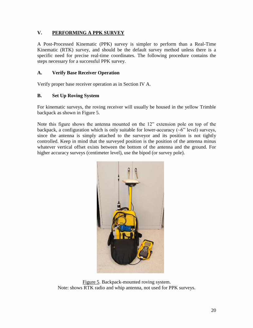
For kinematic surveys, the roving receiver will usually be housed in the yellow Trimble
backpack as shown in Figure 5.
Note this figure shows the antenna mounted on the 12” extension pole on top of the
backpack, a configuration which is only suitable for lower-accuracy (~6” level) surveys,
since the antenna is simply attached to the surveyor and its position is not tightly
controlled. Keep in mind that the surveyed position is the position of the antenna minus
whatever vertical offset exists between the bottom of the antenna and the ground. For
higher accuracy surveys (centimeter level), use the bipod (or survey pole).
Figure 5. Backpack-mounted roving system.
Note: shows RTK radio and whip antenna, not used for PPK surveys.
21
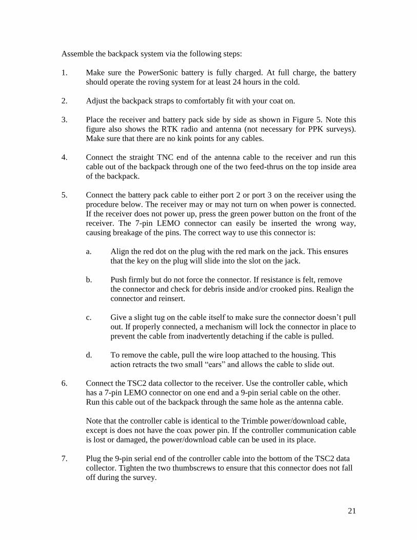
Assemble the backpack system via the following steps:
1. Make sure the PowerSonic battery is fully charged. At full charge, the battery
should operate the roving system for at least 24 hours in the cold.
2. Adjust the backpack straps to comfortably fit with your coat on.
3. Place the receiver and battery pack side by side as shown in Figure 5. Note this
figure also shows the RTK radio and antenna (not necessary for PPK surveys).
Make sure that there are no kink points for any cables.
4. Connect the straight TNC end of the antenna cable to the receiver and run this
cable out of the backpack through one of the two feed-thrus on the top inside area
of the backpack.
5. Connect the battery pack cable to either port 2 or port 3 on the receiver using the
procedure below. The receiver may or may not turn on when power is connected.
If the receiver does not power up, press the green power button on the front of the
receiver. The 7-pin LEMO connector can easily be inserted the wrong way,
causing breakage of the pins. The correct way to use this connector is:
a. Align the red dot on the plug with the red mark on the jack. This ensures
that the key on the plug will slide into the slot on the jack.
b. Push firmly but do not force the connector. If resistance is felt, remove
the connector and check for debris inside and/or crooked pins. Realign the
connector and reinsert.
c. Give a slight tug on the cable itself to make sure the connector doesn’t pull
out. If properly connected, a mechanism will lock the connector in place to
prevent the cable from inadvertently detaching if the cable is pulled.
d. To remove the cable, pull the wire loop attached to the housing. This
action retracts the two small “ears” and allows the cable to slide out.
6. Connect the TSC2 data collector to the receiver. Use the controller cable, which
has a 7-pin LEMO connector on one end and a 9-pin serial cable on the other.
Run this cable out of the backpack through the same hole as the antenna cable.
Note that the controller cable is identical to the Trimble power/download cable,
except is does not have the coax power pin. If the controller communication cable
is lost or damaged, the power/download cable can be used in its place.
7. Plug the 9-pin serial end of the controller cable into the bottom of the TSC2 data
collector. Tighten the two thumbscrews to ensure that this connector does not fall
off during the survey.
22
8. Mount the GPS antenna. See Section V.F below for more info regarding backpack
vs. bipod antenna mounting.
a. If mounting the antenna on the backpack, screw the antenna extension
pole onto either stud on the top of the backpack. Screw the Zephyr antenna onto
the top of this pole. Make sure the antenna is snug so that it does not come loose
and rotate during the survey. Connect the 90 degree TNC end of the antenna cable
to the antenna.
b. If mounting the antenna on the bipod, screw the two halves of the main (2-
meter) bipod pole together tightly. Insert this pole into the clamp on the bipod
legs and tighten the clamp. Make sure the conical points on the ends of all legs are
tight.
Screw the Zephyr antenna onto the top of pole and attach the antenna cable. Make
sure you have plenty of slack in this cable between the backpack and the antenna.
For convenience, mount the TSC2 data collector to the bipod pole using the black
plastic mounting bracket.
9. Make sure all cables are free from kinks and zip up the backpack.
C. Program Roving Receiver
The Survey Controller program has a myriad of functions, most of which are designed for
construction-style job site surveys and do not apply to surveys around Palmer. The best
advice for doing surveys is to keep it simple, and this includes programming the roving
receiver. The following procedure contains the minimum steps for correctly setting up a
PPK survey, and should suffice for most if not all PPK surveying tasks.
1. Make sure the TSC2 data collector battery is fully charged. The TSC2 only runs
from this battery; it does not take power from the receiver’s battery. A Cincon
5VDC charger is stored in the small yellow Pelican case.
2. Turn on the TSC2 by pushing the green button. If the Survey Controller program
is not already running, start it by touching “Start” then “Survey Controller” from
the Windows CE menu. A screen with six selections will appear, along with a bar
on the right hand side which contains receiver status information. The TSC2 has a
touch screen which is operated by the stylus stored in the top of its casing. A pen
or pencil will also work. You can always get back to this main screen by touching
the “Menu” button on the right hand side of the display.
3. Now, create a new “Job”, or return to an existing job if you want to add more data
to it. A Job refers to a set of data with something in common (such as work for a
23
specific science project or work on a particular day), and can contain multiple
RTK and/or PPK surveys performed over multiple days.
a. Touch “Files” then “New Job”. Type in the job name and touch “Enter”.
b. Under “Coord. sys.”, select “No Projection / No Datum”. A projection is a
transformation of 3-D geodetic coordinates into a 2-D plane. You can
choose a projection during the post-processing; there is no need to define
this now. When the “Site Calibration” menu appears, hit “Store” to accept
the default parameters.
c. There is no need to change any other parameter in this menu, except filling
in the Description, Operator, or Notes text fields if you wish. These fields
are accessed by touching the “1/2” box to scroll down to the next menu
page. When you’re done, touch “Accept” to return to the main menu.
4. The next step is configuring the “Survey Style”. A survey style refers to the type
of survey being conducted, in this case PPK. The PPK survey style has already
been defined in the data collector, however you should verify that all these
settings are correct before proceeding.
a. Touch “Configuration” then “Survey Styles” on the main screen, then
touch “PPK”.
b. Under “Rover Options”, verify the following:
i. Survey Type: PP kinematic
ii. Logging interval: 5.0s is a common interval. However, if you
are going to traverse continuous contours
and want a higher logging rate to increase
the spatial resolution, select 1.0s or 2.0s.
iii. Elevation mask: 10 degrees
iv. PDOP mask: 6.0
v. Logging device: Controller
vi. Auto file names: box checked
vii. Antenna Type: Zephyr
viii. Measured to: Bottom of antenna mount
ix. Antenna Height: Enter in the vertical distance between the
ground and the bottom plane of the antenna.
If you have the antenna mounted on the
backpack, have another person measure this
distance when you are standing straight with
the backpack. You can enter in this vertical
distance in inches or meters, for example a
1.92 meter distance could be entered in as
“1.92m” or “75.59in”. If you have the
24
antenna on the bipod, this distance will be
“2.0m”. If you are using the bipod plus the
antenna extension pole, the distance will be
“3.829m” (i.e. 2 meters plus 6 feet).
x. Tracking Use L2e: Yes
xi. Tracking GPS L2C: box not checked
xii. Tracking GLONASS: box not checked
c. Touch “Accept” to return to the RTK Survey Style menu
d. Under “Topo Point”, verify the following:
i. Auto point step size: 1
This number is an increment for the last
character of your point file name. For
example, if you measure point
“palmer1”, the data collector will
assume the next point you want to measure
is “palmer2”. This number can be
negative as well, for example if you’re
counting down as you survey the ATM line
poles. The index also applies to letters, i.e.
the data collector would assume the point
after “palmer” would be “palmes”. Of
course you can change these point names
during the survey before you measure them.
ii. Auto store point: box checked
iii. Number of meas: 3
iv. Quality control: QC1
v. Occupation time: 0m15s
The combination of (iii) and (v) means that
each “topo point” will require both a 15-
second occupation and three observations
(if you previously set using “Logging
interval” to 5 seconds each).
e. Touch “Accept” to return to the PPK Survey Style menu. Touch “Store”
and the “Escape” to save the settings and return to the main screen.
D. Measure Points and/or Contours
The receiver is now ready to begin the survey. Go outside and verify that the receiver is
tracking satellites by watching the satellite display in the right-hand side status bar on the
controller. At Palmer, you ought to have between 7 and 12 satellites in view at all times.
A bare minimum of 4 satellites is required to calculate a position, however, a practical
minimum is 5. If 5 or more satellites are in view, proceed with the survey.
25
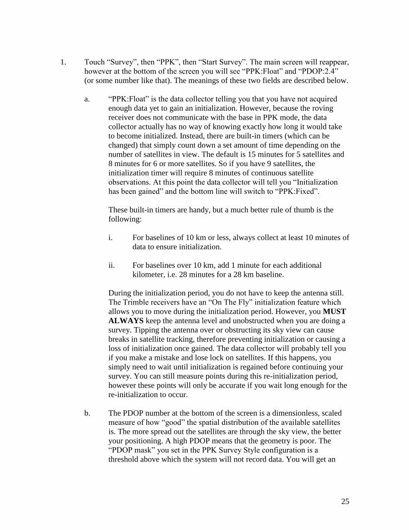
1. Touch “Survey”, then “PPK”, then “Start Survey”. The main screen will reappear,
however at the bottom of the screen you will see “PPK:Float” and “PDOP:2.4”
(or some number like that). The meanings of these two fields are described below.
a. “PPK:Float” is the data collector telling you that you have not acquired
enough data yet to gain an initialization. However, because the roving
receiver does not communicate with the base in PPK mode, the data
collector actually has no way of knowing exactly how long it would take
to become initialized. Instead, there are built-in timers (which can be
changed) that simply count down a set amount of time depending on the
number of satellites in view. The default is 15 minutes for 5 satellites and
8 minutes for 6 or more satellites. So if you have 9 satellites, the
initialization timer will require 8 minutes of continuous satellite
observations. At this point the data collector will tell you “Initialization
has been gained” and the bottom line will switch to “PPK:Fixed”.
These built-in timers are handy, but a much better rule of thumb is the
following:
i. For baselines of 10 km or less, always collect at least 10 minutes of
data to ensure initialization.
ii. For baselines over 10 km, add 1 minute for each additional
kilometer, i.e. 28 minutes for a 28 km baseline.
During the initialization period, you do not have to keep the antenna still.
The Trimble receivers have an “On The Fly” initialization feature which
allows you to move during the initialization period. However, you MUST
ALWAYS keep the antenna level and unobstructed when you are doing a
survey. Tipping the antenna over or obstructing its sky view can cause
breaks in satellite tracking, therefore preventing initialization or causing a
loss of initialization once gained. The data collector will probably tell you
if you make a mistake and lose lock on satellites. If this happens, you
simply need to wait until initialization is regained before continuing your
survey. You can still measure points during this re-initialization period,
however these points will only be accurate if you wait long enough for the
re-initialization to occur.
b. The PDOP number at the bottom of the screen is a dimensionless, scaled
measure of how “good” the spatial distribution of the available satellites
is. The more spread out the satellites are through the sky view, the better
your positioning. A high PDOP means that the geometry is poor. The
“PDOP mask” you set in the PPK Survey Style configuration is a
threshold above which the system will not record data. You will get an
26
error message if the PDOP exceeds this value. A common source of high
PDOP is a partial obstruction of the antenna’s sky view.
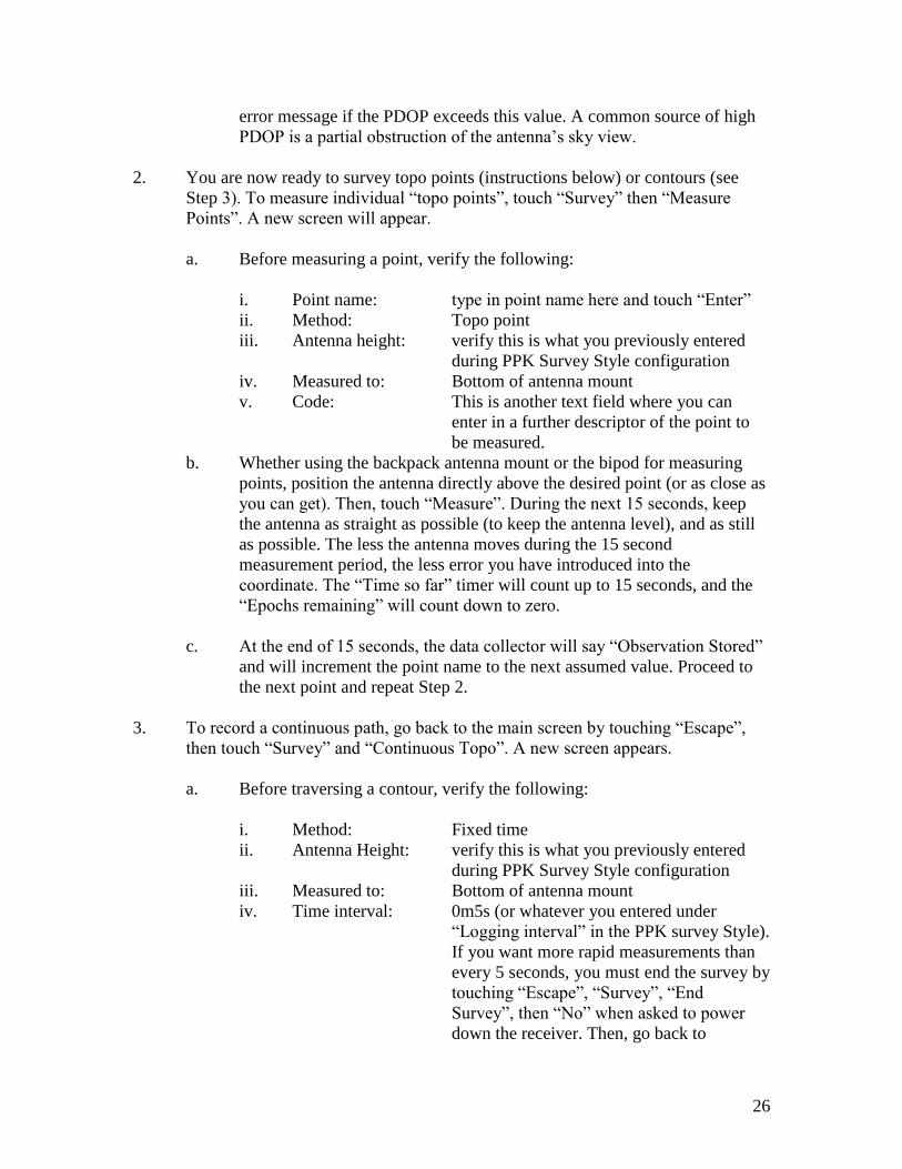
2. You are now ready to survey topo points (instructions below) or contours (see
Step 3). To measure individual “topo points”, touch “Survey” then “Measure
Points”. A new screen will appear.
a. Before measuring a point, verify the following:
i. Point name: type in point name here and touch “Enter”
ii. Method: Topo point
iii. Antenna height: verify this is what you previously entered
during PPK Survey Style configuration
iv. Measured to: Bottom of antenna mount
v. Code: This is another text field where you can
enter in a further descriptor of the point to
be measured.
b. Whether using the backpack antenna mount or the bipod for measuring
points, position the antenna directly above the desired point (or as close as
you can get). Then, touch “Measure”. During the next 15 seconds, keep
the antenna as straight as possible (to keep the antenna level), and as still
as possible. The less the antenna moves during the 15 second
measurement period, the less error you have introduced into the
coordinate. The “Time so far” timer will count up to 15 seconds, and the
“Epochs remaining” will count down to zero.
c. At the end of 15 seconds, the data collector will say “Observation Stored”
and will increment the point name to the next assumed value. Proceed to
the next point and repeat Step 2.
3. To record a continuous path, go back to the main screen by touching “Escape”,
then touch “Survey” and “Continuous Topo”. A new screen appears.
a. Before traversing a contour, verify the following:
i. Method: Fixed time
ii. Antenna Height: verify this is what you previously entered
during PPK Survey Style configuration
iii. Measured to: Bottom of antenna mount
iv. Time interval: 0m5s (or whatever you entered under
“Logging interval” in the PPK survey Style).
If you want more rapid measurements than
every 5 seconds, you must end the survey by
touching “Escape”, “Survey”, “End
Survey”, then “No” when asked to power
down the receiver. Then, go back to
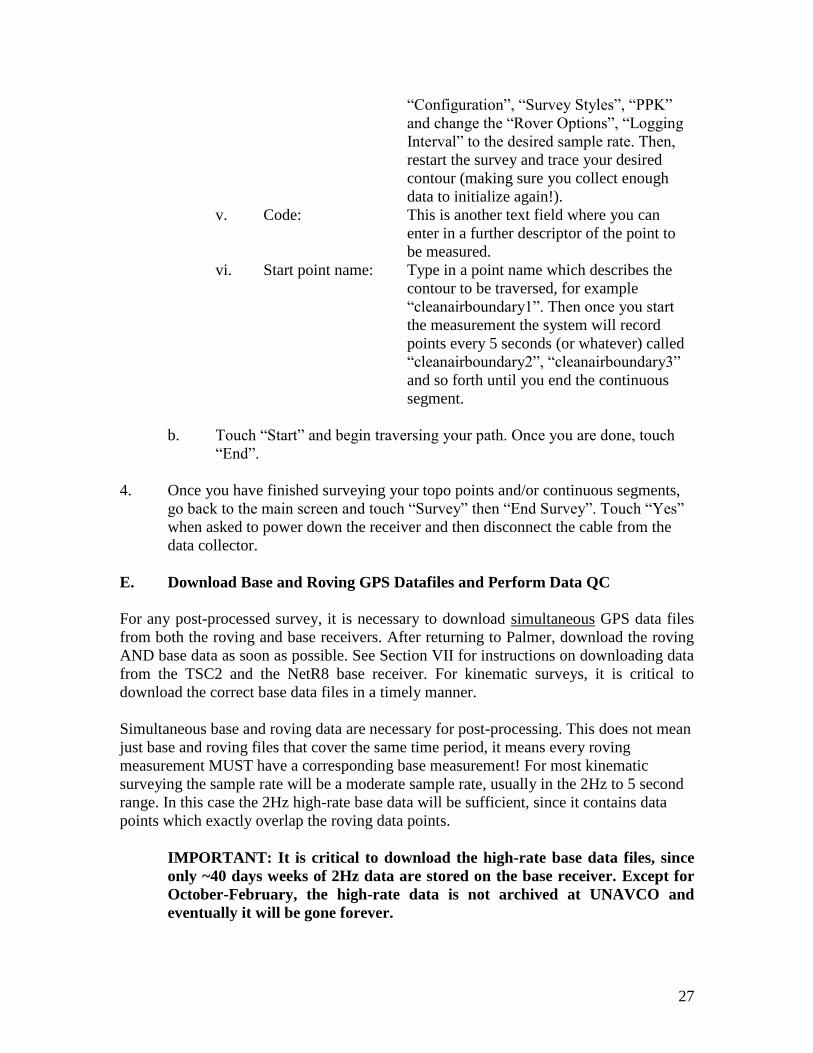
27
“Configuration”, “Survey Styles”, “PPK”
and change the “Rover Options”, “Logging
Interval” to the desired sample rate. Then,
restart the survey and trace your desired
contour (making sure you collect enough
data to initialize again!).
v. Code: This is another text field where you can
enter in a further descriptor of the point to
be measured.
vi. Start point name: Type in a point name which describes the
contour to be traversed, for example
“cleanairboundary1”. Then once you start
the measurement the system will record
points every 5 seconds (or whatever) called
“cleanairboundary2”, “cleanairboundary3”
and so forth until you end the continuous
segment.
b. Touch “Start” and begin traversing your path. Once you are done, touch
“End”.
4. Once you have finished surveying your topo points and/or continuous segments,
go back to the main screen and touch “Survey” then “End Survey”. Touch “Yes”
when asked to power down the receiver and then disconnect the cable from the
data collector.
E. Download Base and Roving GPS Datafiles and Perform Data QC
For any post-processed survey, it is necessary to download simultaneous GPS data files
from both the roving and base receivers. After returning to Palmer, download the roving
AND base data as soon as possible. See Section VII for instructions on downloading data
from the TSC2 and the NetR8 base receiver. For kinematic surveys, it is critical to
download the correct base data files in a timely manner.
Simultaneous base and roving data are necessary for post-processing. This does not mean
just base and roving files that cover the same time period, it means every roving
measurement MUST have a corresponding base measurement! For most kinematic
surveying the sample rate will be a moderate sample rate, usually in the 2Hz to 5 second
range. In this case the 2Hz high-rate base data will be sufficient, since it contains data
points which exactly overlap the roving data points.
IMPORTANT: It is critical to download the high-rate base data files, since
only ~40 days weeks of 2Hz data are stored on the base receiver. Except for
October-February, the high-rate data is not archived at UNAVCO and
eventually it will be gone forever.
28
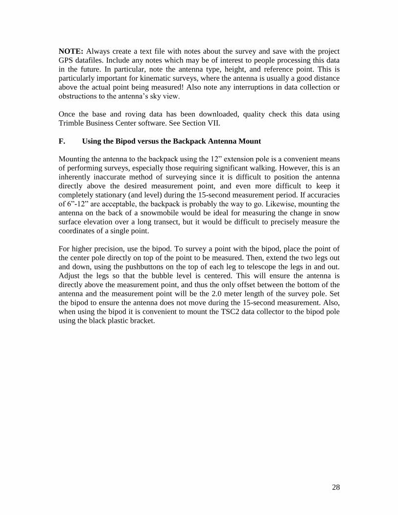
NOTE: Always create a text file with notes about the survey and save with the project
GPS datafiles. Include any notes which may be of interest to people processing this data
in the future. In particular, note the antenna type, height, and reference point. This is
particularly important for kinematic surveys, where the antenna is usually a good distance
above the actual point being measured! Also note any interruptions in data collection or
obstructions to the antenna’s sky view.
Once the base and roving data has been downloaded, quality check this data using
Trimble Business Center software. See Section VII.
F. Using the Bipod versus the Backpack Antenna Mount
Mounting the antenna to the backpack using the 12” extension pole is a convenient means
of performing surveys, especially those requiring significant walking. However, this is an
inherently inaccurate method of surveying since it is difficult to position the antenna
directly above the desired measurement point, and even more difficult to keep it
completely stationary (and level) during the 15-second measurement period. If accuracies
of 6”-12” are acceptable, the backpack is probably the way to go. Likewise, mounting the
antenna on the back of a snowmobile would be ideal for measuring the change in snow
surface elevation over a long transect, but it would be difficult to precisely measure the
coordinates of a single point.
For higher precision, use the bipod. To survey a point with the bipod, place the point of
the center pole directly on top of the point to be measured. Then, extend the two legs out
and down, using the pushbuttons on the top of each leg to telescope the legs in and out.
Adjust the legs so that the bubble level is centered. This will ensure the antenna is
directly above the measurement point, and thus the only offset between the bottom of the
antenna and the measurement point will be the 2.0 meter length of the survey pole. Set
the bipod to ensure the antenna does not move during the 15-second measurement. Also,
when using the bipod it is convenient to mount the TSC2 data collector to the bipod pole
using the black plastic bracket.
29
VI. PERFORMING AN RTK SURVEY
The setup for a Real-Time Kinematic (RTK) survey is similar to a Post-Processed
Kinematic (PPK) survey. For an RTK survey, first follow steps in Sections V.A through
V.C.2 above (i.e. everything up to but not including creating the new “Job”). Also, you
must connect the Pacific Crest RTK roving radio to the R7. Connect the 5-pin LEMO end
of the radio cable to the radio. Then connect the 7-pin LEMO end to Port 3 on the R7,
and the radio’s power LED will turn on (if the R7 receiver is on). Be sure to note which
end is which, since trying to jam the 5-pin LEMO end into a 7-pin LEMO (and vice-
versa) will break the pins! Then, proceed as follows:
A. Program Roving Receiver
The Survey Controller program has a myriad of functions, most of which are designed for
construction-style job site surveys and do not apply to surveys around Palmer. The best
advice for doing surveys is to keep it simple, and this includes programming the roving
receiver. The following procedure contains the minimum steps for correctly setting up an
RTK survey, and should suffice for most if not all RTK surveying tasks.
1. Make sure the TSC2 data collector battery is fully charged. The TSC2 only runs
from this battery; it does not take power from the receiver’s battery. A Cincon
5VDC charger is available for the TSC2.
2. Turn on the TSC2 by pushing the green button. If the Survey Controller program
is not already running, start it by touching “Start” then “Survey Controller” from
the Windows CE menu. A screen with six selections will appear, along with a bar
on the right hand side which contains receiver status information. The TSC2 has a
touch screen which is operated by the stylus stored in the top of its casing. A pen
or pencil will also work. You can always get back to this main screen by touching
the “Menu” button on the right hand side of the display.
3. Now, create a new “Job”, or return to an existing job if you want to add more data
to it. A Job refers to a set of data with something in common (such as work for a
specific science project or work on a particular day), and can contain multiple
RTK and/or PPK surveys performed over multiple days.
a. Touch “Files” then “New Job”. Type in the job name and touch “Enter”.
b. Under “Coord. sys.”, select a projection. A projection is a transformation
of 3-D geodetic coordinates into a 2-D plane. Enabling a projection allows
you to navigate to precise points in RTK mode. A widely used system is
the Universal Transverse Mercator projection, or UTM. Palmer Station is
in UTM Zone 20 South. The “Units (Dist.)” should be meters.
c. There is no need to change any other parameter in this menu, except filling
in the Description, Operator, or Notes text fields if you wish. These fields
30
are accessed by touching the “1/2” box to scroll down to the next menu
page. When you’re done, touch “Accept”.
4. The next step is configuring the “Survey Style”. A survey style refers to the type
of survey being conducted, in this case RTK. The RTK survey style has already
been defined in the data collector, however you should verify that all these
settings are correct before proceeding.
a. Touch “Configuration” then “Survey Styles” on the main screen, then
touch “RTK”.
b. Under “Rover Options”, verify the following:
i. Survey Type: RTK
ii. Broadcast format: CMR+
iii. Use station index: 0
iv. Prompt station index: box not checked
v. Satellite differential: Off
vi. Ignore health: N/A
vii. Elevation mask: 10 degrees
viii. PDOP mask: 6.0
x. Antenna type: Compact L1/L2 (or Zephyr Geodetic)
x. Measured to: Bottom of antenna mount
xi. Antenna height: Enter in the vertical distance between the
ground and the bottom plane of the antenna.
If you have the antenna mounted on the
backpack, have another person measure this
distance when you are standing straight with
the backpack. You can enter in this vertical
distance in inches or meters, for example a
1.92 meter distance could be entered in as
“1.92m” or “75.59in”. If you have the
antenna on the bipod, this distance will be
“2.0m”. If you are using the bipod plus the
antenna extension pole, the distance will be
“3.829m” (i.e. 2 meters plus 6 feet).
xii. Serial number: not necessary
xiii. Tracking Use L2e: Yes
xiv. Tracking L2C: box not checked
xv. Tracking GLONASS: box not checked
c. Touch “Accept” to return to the RTK Survey Style menu
31
d. Under “Rover radio”, check the following:
i. Type: Pacific Crest
ii. Route through SC: box not checked
iii. Controller port: COM1
iv. Receiver port: Port 3
v. Baud rate: 9600
vi. Parity: None
e. Touch “Accept” to return to the RTK Survey Style menu
f. Under “Topo Point”, check the following:
i. Auto point step size: 1
ii. Auto store point: box checked
iii. Number of measurements: 15
Notice that the number of
measurements here is 15, as opposed
to 3 in the PPK survey style. This is
because the RTK broadcasts are
made at a rate of 1 per second by the
base radio. Thus, 15 measurements
are taken during the 15 second
occupation.
iv. Precision/Auto tolerance: box checked
v. Quality control: QC1
vi. Occupation time: 0m15s
g. Touch “Accept” to return to the RTK Survey Style menu. Touch “Store”
to save the settings and then touch “Escape” to return to the main screen.
B. Turn on Base Radio
Check that the Pacific Crest base radio is plugged into the 12 VDC Toshiba power supply
and that the 9-pin serial connector is securely attached to the power/download cable to
the NetR8 receiver. Upon power-up, the Tx light should start blinking once per second.
Once the base radio is powered and transmitting, you should see the Rx light on the
roving radio start to blink once per second (even if you are still inside the building).
C. Measure Points and/or Contours
The receiver is now ready to begin the survey. Procedurally, surveying points and
contours in an RTK survey is similar to a PPK survey. First, go outside and verify that
the receiver is tracking satellites by watching the satellite display in the right-hand side
status bar. At Palmer, you ought to have between 7 and 12 satellites in view at all times.
32
A bare minimum of 4 satellites is required to calculate a position, however, a practical
minimum is 5. If 5 or more satellites are in view, proceed with the survey.
Also, verify that the receiver’s radio is receiving the RTK broadcasts from the base radio.
A small icon should be present in the upper right hand corner of the TSC2 display which
looks like a box with an antenna. The R7 receiver itself also has a radio LED, which
should blink GREEN approximately once per second. If a good number of satellites are
being tracked and there is a solid radio link, then:
1. Touch “Survey”, then “RTK”, the “Start Survey”. The main screen will reappear,
however at the bottom of the screen you will see “RTK:Float”, “H:1.9m”, and
“V3.2m” (or some numbers like these). The meanings of these three fields are
described below.
a. “RTK:Float” is the data collector telling you that you have not
acquired enough data to initialize the survey. With RTK, the data
collector will process the data received from the base and roving
receivers and tell you when the initialization has been gained,
unlike the PPK system where a timer simply counts down a
conservative amount of time which should yield an initialization
during post-processing. The amount of time it takes to get
initialized varies with baseline length. Around the immediate
Palmer Station area, it should take one minute or so. Farther away,
up to the ~5 km limit for RTK, it might take 5 minutes. Once
initialization has been gained, the data collector will tell you so and
the bottom of the screen will change to “RTK:Fixed”. An
additional “RMS” field will appear as well, which is an
approximate value of the overall precision of the baseline.
b. The H:, V:, and RMS: fields give the user information about the
horizontal, vertical, and overall precision of the baseline solution
between the base and the rover. Before initialization, the
“RTK:Float” field is accompanied by H: and V: precisions of a
few meters or so. Thus, until this $25,000 differential GPS
system has gathered enough data to precisely calculate the baseline
between base and rover, the coordinates measured by the roving
receiver are no better than a $200 hand-held Garmin GPS unit!
After initialization, you will see these values decrease drastically,
to a few centimeters or so. In general, GPS accuracies are twice as
good in the horizontal plane than the vertical, since there are
satellites available for all 360 degrees around the horizontal plane
but the earth blocks out 180 degrees of the vertical plane.
2. You are now ready to survey points (instructions below) or contours (see Step 3).
To measure individual “topo points”, touch “Survey” then “Measure Points”. A
new screen will appear.
33
a. Before measuring a point, verify the following:
i. Point name: type in point name here and touch “Enter”
ii. Method: Topo point
iii. Antenna height: verify this is what you previously entered
during RTK Survey Style configuration
iv. Measured to: Bottom of antenna mount
v. Code: This is another text field where you can
enter in a further descriptor of the point to
be measured.
b. Whether using the backpack antenna mount or the bipod for measuring
points, position the antenna directly above the desired point (or as close as
you can get). Touch “Measure”. During the next 15 seconds, keep the
antenna as straight as possible (to keep the antenna level), and as still as
possible. The less the antenna moves during the 15 second measurement
period, the less error you have introduced into the coordinate. The “Time
so far” timer will count up to 15 seconds, and the “Epochs remaining” will
count down to zero.
c. At the end of 15 seconds, the data collector will say “Observation Stored”
and will increment the point name to the next assumed value. Proceed to
the next point and repeat Step 2.
3. To record a continuous path, go back to the main screen by touching “Escape”,
then touch “Survey” and “Continuous Topo”. A new screen appears.
a. Before traversing a contour, verify the following:
i. Method: Fixed time
ii. Antenna Height: verify this is what you previously entered
during RTK Survey Style configuration
iii. Measured to: Bottom of antenna mount
iv. Time interval: 0m1s
Since RTK broadcasts at once per second,
you can set the time interval between points
to any multiple of 1 second you want. Select
a convenient value based on your rate of
travel that will yield data points at a good
spatial resolution.
v. Code: This is another text field where you can
enter in a further descriptor of the point to
be measured.
34
vi. Start point name: Type in a point name which describes the
contour to be traversed, for example
“powerline1”. Then once you start
the measurement the system will record
points every 5 seconds (or whatever) called
“powerline2”, “powerline3” and so forth
until you end the continuous segment.
b. Touch “Start” and begin traversing your path. Once you are done, touch
“End”.
4. Once you have finished surveying your topo points and/or continuous segments,
go back to the main screen and touch “Survey” then “End Survey”. Touch “Yes”
when asked to power down the receiver and then disconnect the cable from the
data collector.
D. Navigating to a Point
A primary advantage of the RTK system is the ability to navigate to a precise point. This
function is similar to the navigation function of a hand-held GPS receiver, but with much
higher accuracy. You can either navigate back to a point you just measured in the current
survey, or navigate to coordinates that you entered into the data collector prior to the
survey.
1. Entering a coordinate into the data collector prior to a survey
To load coordinates into the data collector, touch “Key in” from the main screen,
then “Points”. By touching the “Options” button, you can choose to enter “Grid”
coordinates (projected coordinates, i.e. northing, easting, elevation) or WGS-84
coordinates (geodetic coordinates, i.e. latitude, longitude, height). For geodetic
coordinates, you can enter longitude/latitude in the form ddd mm ss.ssss N/S (or
E/W), where ddd is degrees, mm is minutes, and ss.ssss is decimal seconds.
Alternatively, you can enter them in straight decimal degrees: ddd.ddddddddd
N/S (or E/W). Heights are entered in meters. These points will become part of the
current job.
It is beyond the scope of this document to describe the intricacies of different
projections and geodetic coordinate systems, however there is one key point to
keep in mind when trying to locate a point that you typed in. Any geodetic
coordinate you enter must be in the WGS84 datum. This is because of the way the
Palmer Station base station coordinates were derived. The Palmer base coordinate
is in WGS-84; thus all baselines calculated from a survey will end up in WGS-84
unless you specifically perform a datum transformation. If you have latitude,
longitude, height values in another datum (such as ITRF-05 or NAD-83), you
might well navigate to a point that is a good distance away from the point you
were seeking. But if you are trying to locate a point that was measured during a
35
previous survey with this RTK system, that point was almost certainly calculated
in WGS-84, so you can simply enter it in.
2. Navigating to a Point
Once you key in a point, it becomes part of the current job along with all the other
points you have surveyed during the job. To navigate to any point, touch
“Instrument” from the main screen, then “Navigate to Point”. The “Find a Point”
screen will appear. Now:
a. Touch the arrow to the right of the “Point name” box and choose “List”.
b. Select the desired point and then verify the settings:
i. Navigate: To the point
ii. Antenna Height: verify this is what you previously entered
during PPK Survey Style configuration
iii. Measured to: Bottom of antenna mount
iv. Code: N/A unless you typed in a code when this
point was entered or surveyed
c. Touch “Start”. A screen will appear which tells you how far you need to
go in each direction to reach the point. An arrow also appears which
indicates the direction of the desired point. When you get close enough the
display shifts from “coarse” to “fine” mode. Here, the point will appear as
a bullseye and the arrow will shift to a crosshair.
E. Download Roving GPS Datafiles and Perform Data QC
When you return to Palmer, download the data as soon as possible. With RTK surveys it
only necessary to download roving data, since the base data has already been used to
solve for precision coordinates. See Section VII.
NOTE: Always create a text file with notes about the survey and save with the project
GPS datafiles. Include any notes which may be of interest to people processing this data
in the future. In particular, note the antenna type, height, and reference point. This is
particularly important for kinematic surveys, where the antenna is usually a good distance
above the actual point being measured! Also note any interruptions in data collection or
obstructions to the antenna’s sky view.
Once the roving data has been downloaded, you can open and view it using Trimble
Business Center software. The data has already been processed by the RTK system, but
TBC can be used to view and export RTK data sets.
36
F. RTK Repeater
If an RTK survey is required beyond the area within line-of-sight of the RTK base radio
antenna, a portable repeater is available. Position the repeater such that it has line of sight
to both Palmer Station as well as the survey area. The repeater radio will rebroadcast the
RTK signal from the RTK base radio.
This system is assembled with an RTK repeater radio and whip antenna, with a battery
and bipod mount. Mount the antenna on top of the bipod and connect to the repeater
radio. Store the repeater radio and battery inside the yellow pelican case, and position this
case at the base of the bipod. The LED’s on the repeater radio (Rx and Tx) should blink
once per second.
37
VII. ADDITIONAL SYSTEM INFORMATION
A. Downloading data from the NetR8 base
Data can be downloaded from the base station from any computer on the Palmer local
network. First, open a web browser and connect to:
http://157.132.224.74
This receiver is configured to allow anonymous users to download data without a
username and password. However, if prompted, the username and password for Palmer
users are:
Username: pal2
Password: gps
Users can also log in by clicking the Security tab on the left-hand menu. This menu also
allows you to see how many satellites the receiver is tracking, what data files are being
logged, and other configuration information. However, you can only download data using
the Palmer user account and cannot change any of these parameters. Configuration
changes are done remotely by UNAVCO using a separate account; contact UNAVCO for
any changes or requests.
To download data, next click on the Data Logging tab, then Data Files. Click on the
Internal directory then navigate to the directory where the desired files are stored. When
you locate the file(s) you want, click on the filename to download. Note that you cannot
download any files that are currently being written to. The NetR8 is configured to log
files in the following locations:
24-hour 15-second datafiles
/Internal/YYYYMM/24hr15sc/PAL2YYYYMMDD0000A.T01
60-minute 2-Hz datafiles
/Internal/YYYYMM/DD/1hr2hz/PAL2YYYYMMDDHH00B.T01
60-minute 10-Hz datafiles
/Internal/YYYYMM/DD/1hr10hz/PAL2YYYYMMDDHH00C.T01
Each of these file types is allocated a certain portion of the NetR8 memory. When this
section of memory is full, the oldest files are deleted. The NetR8 stores approximately
800 days of 15-second data, 40 days of 2Hz data, and 8 days of 10Hz data.
B. Downloading Data from the TSC2 Data Collector
Upon completion of a PPK or RTK survey, download files from the controller according
to the following steps. Two programs are needed to download data from the TSC2:
38
Microsoft ActiveSync and Trimble Data Transfer. Both programs are installed on the
Science Tech computer in the TerraLab, and it is assumed that this computer will be used
for data downloading.
1. Turn on the TSC2 and use the flat-to-square connector USB cable in the yellow
Pelican case to attach the data collector to the computer
2. When you hook up the TSC2, ActiveSync should start up and read “Connected”.
Don’t set up a “partnership”, just close that window if it appears. Also, you may
get a MS Outlook error message along the way. If ActiveSync doesn’t start up
automatically, try starting it. If it doesn’t automatically say “Connected”, try
turning the TSC2 on and off, and disconnecting/reconnecting the USB cable.
Eventually it will work.
3. Open Trimble Data Transfer from the Start menu. Shortcuts for ActiveSync,
Trimble Data Transfer, and other GPS utilities are also stored in the UNAVCO
folder on the Desktop.
4. If the top right-hand display doesn’t automatically say “Connected”, select
“Survey Controller on ActiveSync” from the “Device” window at the top left.
Click the Green button to connect, and the top right display should tell you that
you are connected.
5. Click “Add” and then select the Job file you want to download. In this window
you can also browse to select the directory to which the files will be downloaded.
6. Once the Job file is selected, click “Transfer All”. You should see a “Receiving”
window appear, followed by a “Converting” window with little gears turning. The
“Converting” window indicates the compressed .T00 files are being
uncompressed to .dat files. A “Transfer Completed” window will then appear,
signaling the download is finished.
C. Downloading Data from the R7 Roving Receiver
Although “static” surveys will be rare at Palmer Station, occasions will occur when this is
necessary. In this case, the TSC2 data collector will not be used. Rather, data will be
stored directly on the compact flash card on the R7. There are two ways to download
such data from the R7: directly from the compact flash card, and through the receiver via
the power/download cable. Reading directly from the flash card is the faster method.
To download files from the compact flash card:
1. Open the door at the base of the R7 and remove the compact flash card.
2. Insert the flash card into a suitable reader..
39
3. The compact flash card will appear as a separate drive under “My Computer”,
probably E:\ or F:\. Select the desired files and copy to the computer.
4. When copying straight from compact flash, you are copying the compressed .T00
(or .T01) files. Before loading these into Trimble Business Center for
processing, they must be uncompressed. On a computer with Trimble Data
Transfer utility installed, right-click on the filename and select “Convert to DAT”.
To download files through the receiver, the Trimble Data Transfer utility is needed. This
program is installed on the Science Tech computer in the Green House, and it is assumed
that this computer will be used for data downloading.
1. Carefully connect LEMO end of the power/download cable to port 2 on the R7.
Connect the coaxial power connector to the Trimble 18 VDC power supply.
Connect the 9-pin serial end to a serial port on the computer, or a USB-serial
adapter. Turn on the R7.
2. Open Trimble Data Transfer from the Start menu.
3. If the top right-hand display doesn’t automatically say “Connected”, select
“Trimble R7 on COMX” from the “Device” window at the top left, where COMX
is the serial port on the computer. Click the Green button. The top right display
should tell you that you are connected.
4. Click “Add” and then select the files you want to download. In this window
you can also browse to select the directory to which the files will be downloaded.
5. Once your files are selected, click “Transfer All”. You should see a
“Receiving” window appear, then a “Converting” window with little gears
turning. The “Converting” window indicates the compressed .T00 files are being
uncompressed to .dat files. A “Transfer Completed” window will then appear,
when the download is finished.
D. Base Coordinates
The coordinates of monument PALM are:
Latitude: 64º 46’ 30.32726” S WGS84
Longitude: 64º 03’ 04.04752” W WGS84
Ellipsoidal Height: 30.942 m WGS84
These coordinates are broadcast as part of the RTK data stream; therefore all RTK
solutions are automatically referenced to this position.
These coordinates refer to the survey mark which is 0.0794m below the bottom of the
Ashtec antenna; thus during postprocessing, these PAL2 base coordinates are “0.0794 m”
40
to “bottom of antenna mount”. This coordinate is programmed into the NetR8, and will
be written into each data file by the NetR8 receiver. However, always verify the base
coordinate AND the antenna height when doing postprocessing.
E. Software
The TerraLab Office PC at Palmer has all software necessary for operating the GPS
system. Following is a list of software programs and their purposes. A DVD for Trimble
Business Center is also stored with the UNAVCO equipment. The installation files for
Trimble Data Transfer Utility and Microsoft ActiveSync are available from
www.trimble.com and www.microsoft.com respectively.
1. Trimble Business Center. This program is used for postprocessing PPK and static
survey data as well as viewing RTK survey data. This software should be used by
surveyors to quality check data soon after collection; see Section H below.
A detailed how-to manual for this software is outside the scope of this document,
however the software itself contains a useful Help menu. When possible, users
intending to do on-site processing of GPS data should schedule training ahead of
time at the UNAVCO office or their home institution. Contact UNAVCO for
more information.
2. Trimble Data Transfer utility. This program is used to download data from the
TSC2 data collector and from the R7 roving receiver.
3. Trimble Configuration Toolbox. Configure R7 roving receiver for static surveys.
4. Microsoft ActiveSync. Used to connect to the TSC2 data collector for
downloading data with Trimble Data Transfer utility.
F. Quality Checking Data Using Trimble Business Center Software
Final data processing to generate research-quality coordinates is the responsibility of the
science group that requested the survey. However a quick quality check should be
performed by the Science Techs soon after the survey in order to verify that high quality
data was collected. For processing differential GPS data, Trimble Business Center (TBC)
software is installed on the Science Tech computer at Palmer. An installation DVD
should be stored with the UNAVCO equipment.
Instructions for using TBC are provided online at the website listed in Section I.
“How to Quality Check GPS Data Using Trimble Business Center”
Note that TBC cannot be used without a license. UNAVCO maintains a license server
with several licenses that can be checked out by remote users. Therefore, in order to use
TBC the computer at Palmer must be online.