Embed Size (px)
Citation preview

USERS MANUAL / GEBRUIKERSHANDLEIDING BETRIEBSANLEITUNG / MANUEL D’UTILISATION
MANUAL DE UTILIZACION / INSTRUZIONI PER L’USO
Lithium-ion Battery
MLi Ultra 12/2500 MLi Ultra 12/5000 MLi Ultra 24/5000
MASTERVOLT
Snijdersbergweg 93
1105 AN Amsterdam
The Netherlands
Tel.: +31-20-3422100
Fax.: +31-20-6971006
www.mastervolt.com Copyright © 2014 Mastervolt, 10000005784/04 April 2014
ENGLISH: PAGE 1 NEDERLANDS: PAGINA 33 DEUTSCH: SEITE 65 FRANÇAIS: PAGINA 97 CASTELLANO: PAGINA 129 ITALIANO: PAGINA 161

DELIVERY CONTENTS - OVERVIEW
2 Copyright © 2014 Mastervolt / April 2014 / Lithium-ion Battery MLi Ultra / EN
DELIVERY CONTENTS
OVERVIEW
Positive battery terminal at the right with M8 thread
Balance line for serial connection
Connector for safety relay
MasterBus connectors
Negative battery terminal at the left with M8 thread
The two lifting handles cover the battery terminals and
protect the wiring when folded down
The MLi Ultra 12/2500, MLi Ultra 12/5000 and MLi Ultra 12/5000 are part of the Mastervolt MLi Ultra series of Lithium Ion
batteries. These batteries are equipped with an integrated cell management system which features:
Cell balancing Battery voltage monitoring Battery current monitoring Pre warning when battery is almost empty (communication by means of MasterBus) Battery temperature monitoring (integrated temperature sensor) Communication with other MasterBus devices like chargers and alternators
Li-ion battery
MasterBus cable (3m)
MasterBus terminator
Battery terminal 2x M8 bolt + washer +
spring washer Users manual
Connectors for safety relay + Balance line

TABLE OF CONTENTS
EN / April 2014 / Lithium-ion Battery MLi Ultra / Copyright © 2014 Mastervolt 3
Copyright © 2014 Mastervolt. All rights reserved. Reproduction, transfer, distribution or storage of part or all of the contents in this document in any form without the prior written permission of Mastervolt is prohibited.
TABLE OF CONTENTS: 10000005784/04 April 2014
DELIVERY CONTENTS .............................................................................................................................................................. 2
OVERVIEW ................................................................................................................................................................................. 2
1 SAFETY GUIDELINES AND MEASURES ...................................................................................................................... 5 1.1 General rules ...................................................................................................................................................... 5 1.2 Transportation warnings ..................................................................................................................................... 5 1.3 Disposal of li-ion batteries .................................................................................................................................. 5
2 GENERAL INFORMATION .............................................................................................................................................. 6 2.1 Use of this manual .............................................................................................................................................. 6 2.2 Use of pictograms .............................................................................................................................................. 6 2.3 Validity of this manual ........................................................................................................................................ 6 2.4 Warranty specifications ...................................................................................................................................... 6 2.5 Liability ............................................................................................................................................................... 6 2.6 Identification label ............................................................................................................................................... 6 2.7 Use for intended purpose ................................................................................................................................... 7 2.8 Organizational measures ................................................................................................................................... 7 2.9 Maintenance and repair ...................................................................................................................................... 7 2.10 General safety and installation precautions ........................................................................................................ 7 2.11 Warning regarding life support applications........................................................................................................ 7
3 OPERATION .................................................................................................................................................................... 8 3.1 Charging and discharging................................................................................................................................... 8 3.2 Cell management system ................................................................................................................................... 8 3.3 Safety features ................................................................................................................................................... 8
3.3.1 Reduce charge / discharge ................................................................................................................ 8 3.3.2 Stop charge / discharge event ........................................................................................................... 8 3.3.3 Battery safety event ........................................................................................................................... 9
3.4 Alarm messages ................................................................................................................................................. 9 3.5 MasterBus functionality ...................................................................................................................................... 9 3.6 Maintenance, decommissioning and storage ..................................................................................................... 9 3.7 Manual operation of the safety relay .................................................................................................................. 9
4 INSTALLATION ............................................................................................................................................................. 10 4.1 Unpacking ........................................................................................................................................................ 10 4.2 Required tools: ................................................................................................................................................. 10 4.3 Location to install .............................................................................................................................................. 10 4.4 General installation guidelines .......................................................................................................................... 10 4.5 Minimum safety requirements .......................................................................................................................... 11 4.6 Safety relay and battery fuse ............................................................................................................................ 12
4.6.1 Required materials .......................................................................................................................... 12 4.6.2 Connection ...................................................................................................................................... 12
4.7 Charger settings ............................................................................................................................................... 13 4.8 Charging systems ............................................................................................................................................. 13
4.8.1 System with a Mastervolt Mass Charger or ChargeMaster ............................................................. 14 4.8.2 System with Mastervolt Alpha Pro II regulator ................................................................................. 15 4.8.3 System with a Mastervolt Mass Combi ............................................................................................ 16 4.8.4 Non-Mastervolt charging devices up to 6A AC ................................................................................ 17 4.8.5 Non-Mastervolt charging devices of more than 6A AC .................................................................... 18
TABLE OF CONTENTS
4 Copyright © 2014 Mastervolt / April 2014 / Lithium-ion Battery MLi Ultra / EN
5 COMMISSIONING ......................................................................................................................................................... 19
6 MASTERBUS ................................................................................................................................................................. 20 6.1 What is MasterBus? ......................................................................................................................................... 20 6.2 How to set up a MasterBus network ................................................................................................................. 20 6.3 MasterBus: Monitoring and Configuration of the Li-ion battery ......................................................................... 21
6.3.1 Monitoring ........................................................................................................................................ 21 6.3.2 Alarms ............................................................................................................................................. 22 6.3.3 History ............................................................................................................................................. 22 6.3.4 Configuration ................................................................................................................................... 22 6.3.5 Events ............................................................................................................................................. 23 6.3.6 List of events sources ...................................................................................................................... 24 6.3.7 List of list of event commands ......................................................................................................... 25
6.4 Battery safety event threshold levels ................................................................................................................ 25
7 TROUBLE SHOOTING .................................................................................................................................................. 26
8 MAINTENANCE, DECOMMISSIONING AND STORAGE ............................................................................................. 27 8.1 Maintenance ..................................................................................................................................................... 27 8.2 Taking out of operation ..................................................................................................................................... 27 8.3 Battery replacement ......................................................................................................................................... 27 8.4 Exchanging MasterBus devices ....................................................................................................................... 27 8.5 Storage ............................................................................................................................................................. 27
9 ORDERING INFORMATION .......................................................................................................................................... 28
10 TECHNICAL INFORMATION ........................................................................................................................................ 29 10.1 Specifications ................................................................................................................................................... 29 10.2 Dimensions ....................................................................................................................................................... 30 10.3 Charge, discharge characteristic ...................................................................................................................... 31 10.4 Fuse to cable size ............................................................................................................................................ 31
11 EC DECLARATION OF CONFORMITY ........................................................................................................................ 32

SAFETY GUIDELINES AND MEASURES
EN / April 2014 / Lithium-ion Battery MLi Ultra / Copyright © 2014 Mastervolt 5
1 SAFETY GUIDELINES AND MEASURES 1.1 GENERAL RULES
Observe these instructions and keep them located near the Li-ion Battery for future reference. Work on the Li-ion Battery should be carried out by qualified personnel only. While working on the Li-ion Battery wear protective eye-glasses and clothing. Any uncovered battery material such as electrolyte or powder on the skin or in the eyes must be flushed with plenty of clean water immediately. Then seek medical assistance. Spillages on clothing should be rinsed out with water. Explosion and fire hazard. Terminals of the Li-ion Battery are always alive; therefore do not place items or tools on the Li-ion Battery. Avoid short circuits, too deep discharges and too high charge currents. Use insulated tools. Do not wear any metallic items such as watches, bracelets, et cetera. In case of fire, you must use a type D, foam or CO2 fire extinguisher. Never try to open or dismantle the Li-ion Battery. Electrolyte is very corrosive. In normal working conditions contact with the electrolyte is impossible. If the battery casing is damaged do not touch the exposed electrolyte or powder because it is corrosive. Too deep discharges damage the Li-ion battery seriously and can even be dangerous. Therefore, use of an external safety relay is obligatory. Refer to chapter 4. Li-ion Batteries are heavy. If involved in an accident they can become a projectile! Ensure adequate and secure mounting and always use suitable handling equipment for transportation. Handle with care because Li-ion Batteries are sensitive to mechanical shock.
Li-ion batteries can be charged with a voltage up to 14.6 V (29.2 V). On the other hand, Li-ion batteries can be discharged down to 11.0 (22.0V). Note that this voltage range (11.0-14.6V or 22.0-29.2V) is larger than you may expect from other battery types such as lead-acid batteries. Be aware that these voltages
may exceed the permitted voltages of the connected load(s). Therefore appropriate measures must be taken to avoid damage to the connected load(s).
If charged after the Li-ion battery was discharged below the Discharge cut-off voltage, or when the Li-ion battery is damaged or overcharged, the Li-ion battery can release a harmful mixture of gasses such as phosphate.
Non-compliance with operating instructions, repairs made with other than original parts, or repairs made without authorization render the warranty void. 1.2 TRANSPORTATION WARNINGS
The Li-ion battery must be transported in its original or equivalent package and in an upright position. If the battery is in its package, use soft slings to avoid damage. Do not stand below a Li-ion battery when it is hoisted. Never lift the battery at the terminals, only lift the battery at the handles.
Batteries are tested according to UN Handbook of Tests and Criteria, part III, sub section 38.3 (ST/SG/AC.10/11/Rev.5). For transport the batteries belong to the category UN3480, Class 9, Packaging Group II and have to be transported according to this regulation. This means that for land and sea transport (ADR, RID & IMDG) they have to be packed according to packaging instruction P903 and for air transport (IATA) according to packaging instruction P965. The original packaging satisfies these instructions. 1.3 DISPOSAL OF LI-ION BATTERIES Batteries marked with the recycling symbol must be processed via a recognized recycling agency. By agreement, they may be returned to the manufacturer. Batteries must not be mixed with domestic or industrial waste.
non-spillable

GENERAL INFORMATION
6 Copyright © 2014 Mastervolt / April 2014 / Lithium-ion Battery MLi Ultra / EN
2 GENERAL INFORMATION 2.1 USE OF THIS MANUAL This manual serves as a guideline for the safe and effective installation, operation and maintenance of the Mastervolt MLi-Ultra series of lithium ion batteries further mentioned as “Li-ion Battery” or “Li-ion Batteries”. It is therefore obligatory that every person who works on or with the Li-ion Battery is completely familiar with the contents of this manual, and that he/she carefully follows the instructions contained herein. Only the SINGLE battery installation is described. For systems with more than one single battery, please refer to www.mastervolt.com/batteries. Installation of, and work on the Li-ion Battery, may only be carried out by qualified, authorized and trained personnel, consistent with the locally applicable standards and taking into consideration the safety guidelines and measures (chapter 1 of this manual). Keep this manual at a secure place! 2.2 USE OF PICTOGRAMS Safety instructions and warnings are marked in this manual by the following pictograms:
WARNING A WARNING refers to possible injury to the user or significant material damage to the battery if the user does not (carefully) follow the procedures. CAUTION! Special data, restrictions and rules with regard to preventing damage.
2.3 VALIDITY OF THIS MANUAL All of the specifications, provisions and instructions contained in this manual apply solely to the following products: Part number Description 66012500 Li-ion Battery MLi Ultra 12/2500 66015000 Li-ion Battery MLi Ultra 12/5000 66025000 Li-ion Battery MLi Ultra 24/5000
2.4 WARRANTY SPECIFICATIONS Mastervolt guarantees that the Li-ion Battery has been built according to the legally applicable standards and specifications. Acting not conform instructions and specifications contained in this manual, may damage the battery or it may not fulfill its specifications. All of these matters means that the warranty becomes invalid. The warranty is limited to the costs of repair and/or replacement of the product. Costs for installation labor or shipping of the defective parts are not covered by this warranty. Battery damage as a result of over and undercharging is not compensated. You must take measures to disconnect the Li-ion battery based on (MasterBus) generated alarms by this battery, otherwise warranty becomes invalid. Use of a battery controlled external safety relay is obligatory. (refer to chapter 4). The period and conditions of this warranty are laid down in the general conditions of delivery as registered with the Chamber of Commerce and Industries in Amsterdam number 33279951 and are available on request.
Warranty will void if you fail to use an external safety relay controlled by the Li-ion Battery.
2.5 LIABILITY Mastervolt accepts no liability for: consequential damage due to use of the Li-ion
Battery; possible errors in the manuals and their results.
2.6 IDENTIFICATION LABEL
The identification label is located at the top side of the Li-ion Battery, next to the grip handle (see figure 2-1). Important technical information required for service, maintenance & secondary delivery of parts can be derived from the identification label.
CAUTION! Never remove the identification label.
Figure 2-1:
Identification label

GENERAL INFORMATION
EN / April 2014 / Lithium-ion Battery MLi Ultra / Copyright © 2014 Mastervolt 7
2.7 USE FOR INTENDED PURPOSE 1 The Li-ion Battery is constructed as per the applicable
safety-technical guidelines. 2 Use the Li-ion Battery only:
in a technical correct condition; in a closed, well-ventilated area, protected
against rain, moist, dust and condensation; observing the instructions and specifications in
this manual.
WARNING Never use the Li-ion Battery at locations where there is danger of gas or dust explosion or potentially flammable products!
3 Use of the Li-ion Battery other than mentioned in point
2 is not considered to be consistent with the intended purpose. Mastervolt is not liable for any damage resulting from the above.
2.8 ORGANIZATIONAL MEASURES The user must always: have access to the user's manual; be familiar with the contents of this manual. This
applies in particular to chapter Safety Guidelines and Measures.
2.9 MAINTENANCE AND REPAIR 1 If the electrical installation is switched off during
maintenance and/or repair activities, it should be secured against unexpected and unintentional switching on: switch off all charging systems; switch off the connection with the batteries; be sure that third parties cannot reverse the
measures taken. 2 If maintenance and repairs are required, only use
original spare parts.
2.10 GENERAL SAFETY AND INSTALLATION PRECAUTIONS
Do not expose the Li-ion Battery to rain, snow, spray, moisture, excessive pollution and condensing circumstances. Do not install the Li-ion Battery in a non-ventilated area, overheating may result.
The Li-ion Battery must only be used in combination with a controlled external safety relay (refer to chapter 4).
Short circuiting or reversing polarity will lead to serious damage to the Li-ion Battery, equipment connected to the Li-ion Battery and the wiring. Fuses between batteries and equipment cannot prevent damage caused by reversed polarity and the warranty will be void.
Protect the wiring with fuses, according to the local standards.
Connection and protection must be done in accordance with local standards.
Do not work on the Li-ion Battery or system if it is still connected to a power source. Only allow changes in your electrical system to be carried out by qualified electricians.
Check the wiring at least once a year. Defects such as loose connections, burned cables etc. must be corrected immediately.
2.11 WARNING REGARDING LIFE SUPPORT
APPLICATIONS The Li-ion Battery is not sold for applications in any medical equipment intended for use as a component of any life support system unless a specific written agreement pertaining to such intended use is executed between the manufacturer and Mastervolt. Such agreement will require the equipment manufacturer either to contract additional reliability testing of the Li-ion Battery parts and/or to commit to undertake such testing as a part of the manufacturing process. In addition the manufacturer must agree to indemnify and not hold Mastervolt responsible for any claims arising from the use of the Li-ion Battery in the life support equipment.

OPERATION
8 Copyright © 2014 Mastervolt / April 2014 / Lithium-ion Battery MLi Ultra / EN
3 OPERATION 3.1 CHARGING AND DISCHARGING Use the Li-ion Battery within the specifications as stated in chapter 10. 3.2 CELL MANAGEMENT SYSTEM The Mastervolt Li-ion battery consists of a pack of battery cells. As with all kind of batteries, there is always some kind of unbalance present between the individual cells. During charging of an unbalanced battery pack, one or more cells will reach the maximum state of charge before the other the cells. During discharge the cells that are not fully charged will be depleted prior to the other cells, causing early undervoltage shutdown of the pack. Normally spoken, these early charge and discharge limits reduce the usable capacity of the battery and will shorten the expected lifetime of the pack. But to avoid this kind of premature failure, the Mastervolt Li-ion battery is provided with a Cell Management System. With this system, each cell is conditioned individually. Features of the Cell Management System: Balancing between the different cells. Normally, cells
in a series string receive identical currents. With the Cell Management System current from stronger cells will be transferred to the weaker cells during the charging/ discharging process and idle mode;
Protection of each separate cell from under- and over-charging by voltage monitoring of each individual cell;
Prevention of too deep battery discharges; Monitoring of temperature. Each separate cell as well
as the external temperature of the battery pack is being monitored;
Communication with Mastervolt charge devices to maximize safety and performance;
Pre warnings when the state of charge is becoming low.
WARNING Before using the Li-ion battery, it must be installed and commissioned in accordance with the instructions stated in chapters 4 and 5 of this manual!
3.3 SAFETY FEATURES Under- and over-charging, cell imbalances and excessive temperatures may lead to permanent damage to the Li-ion battery and even to dangerous situations. Therefore the Li-ion battery is provided with several advanced safety features.
WARNING Alarms and warnings generated by the Li-ion battery should not be neglected. It is the user’s responsibility to take adequate measures.
There are three levels of protection: Reduce charge / discharge: reduction of the charge /
discharge current Stop charge / discharge: Interruption of the charge /
discharge current Battery safety event: an “emergency stop” of the
battery 3.3.1 Reduce charge / discharge This is the lowest level of protection. Use of this level of protection is optional. It is triggered if the battery voltage, the voltage of one of the individual cells or the temperature of one of the cells is getting close to the allowed operation specifications. MasterBus events can be programmed to display warnings or to intervene on the electrical system, for instance by reducing the charge voltage (Reduce charge) or by disconnecting peripheral loads (Reduce discharge). See section 6.3 and continued for programming of events. 3.3.2 Stop charge / discharge event At this second level of protection, the Li-ion battery is getting too close to the allowed operation specifications. The Li-ion battery will generate MasterBus controlled event commands to which the electrical installation should respond. Programming of the Stop charge event command is obligatory; programming of the Stop discharge event command is optional. Refer to section 6.3 and continued. If the Li-ion battery generates the Stop charge event, it forces to Mastervolt Mass Charger or ChargeMaster to switch to the float stage, in which a lower charge voltage is used. Other (for instance non-Mastervolt) charging devices will be switched off for 10 minutes before they resume charging.

OPERATION
EN / April 2014 / Lithium-ion Battery MLi Ultra / Copyright © 2014 Mastervolt 9
3.3.3 Battery safety event This is the highest level of protection. It occurs if the commands generated at the second level of protection were neglected. The Battery safety event will trigger the safety relay to cut off the Li-ion battery from the electrical installation. There are two kinds of Battery safety events: a resettable and a non-resettable. See section 6.4 for threshold levels.
WARNING If a non-resettable Battery safety event occurs, the Li-ion battery is damaged. It shall be secured against further use.
If the safety relay has been triggered, act as follows: 1 Disconnect all loads and all charging devices from the
Li-ion Battery. 2 Reset the safety relay(s) to reconnect the Li-ion
battery. To do so, move the safety relay in the REMOTE ON position. See section 3.7.
3 Wait for 1 minute. If the Battery Safety Event triggers again, a non-resettable battery safety event occurred. Do not try to reset the safety relay(s) again. In this case the Li-ion battery is damaged and should not be used anymore. Move the safety relay(s) in the LOCK OFF position and contact a Mastervolt representative for assistance.
4 If the Battery Safety Event was not triggered again, a resettable battery safety event occurred. Check the battery voltage with a suitable voltage meter. If the battery voltage is below 13V (26V for 24V battery), keep the loads disconnected and start charging the Li-ion battery. If the battery voltage is over 13V (26V for 24V battery), check the output voltage of the charging devices. If OK, discharge the Li-ion battery for a while.
Additional MasterBus events can be programmed when the Battery safety event occurs. Refer to section 6.3 and continued.
3.4 ALARM MESSAGES The Li-ion Battery may generate the following Alarm messages that may appear on a MasterBus display: Message What to do?
Battery Safety Battery Safety Event occurred. See section 3.3.3.
Overtemperature The internal temperature of one of the cells is too high. This will also generate a Battery Safety Event. See section 3.3.3
Overcurrent Battery current is >600A for more than 30 seconds. Reduce load immediately
3.5 MASTERBUS FUNCTIONALITY Refer to chapter 6 for advanced MasterBus functionality. The Li-ion battery is able to power the MasterBus network. Refer to section 6.3.4, Configuration: MasterBus Power for setting the battery to MasterBus powering.
CAUTION! The safety systems and the MasterBus network will slowly drain the Li-ion Battery, even if the battery has been disconnected from the electrical system. Refer to section 6.3.4 if you want to disable these control systems for instance when the battery will be put out of operation for a longer time
3.6 MAINTENANCE, DECOMMISSIONING AND
STORAGE Refer to chapter 8
3.7 MANUAL OPERATION OF THE SAFETY RELAY Function Description Action REMOTE ON To connect the Li-ion Battery to load and
charging devices Push button on top of the safety relay until latched
REMOTE OFF To disconnect the Li-ion Battery from load and charging devices
Rotate knob on top of the safety relay to right to release button; then rotate knob to left
LOCK OFF To prevent remote operation Rotate knob on top of the safety relay to right

INSTALLATION
10 Copyright © 2014 Mastervolt / April 2014 / Lithium-ion Battery MLi Ultra / EN
4 INSTALLATION
During installation and commissioning of the Li-ion battery, the Safety Guidelines & Measures are applicable at all times. See chapter 1 of this manual.
4.1 UNPACKING After unpacking, check the contents for possible damage. Check the open clamp voltage with a suitable voltage meter. It should be within the following range: Model Allowed open clamp voltage 12V models 11.0 – 14.5 Volt 24V models 22.0 – 29.0 Volt Do not use the product if it is damaged or if the open clamp voltage is out of range. If in doubt, contact your supplier. 4.2 REQUIRED TOOLS:
Hexagon socket wrench 13mm (M8 bolt) to connect the battery cables to the Li-ion battery (torque: see section 4.4)
Tools to install the wiring. 2 mm flat blade screwdriver to fasten the wiring of the
safety relay; 4 mm flat blade screwdriver to fasten the balance line
wiring A MasterBus control panel (for adjustment of setpoints
and programming of obligatory MasterBus events). Select one from the table below:
Part number Model 77010305 MasterView Easy MkII 77010400 MasterView System panel 77030100 MasterBus USB interface
(required as interface between your PC and the MasterBus network)
4.3 LOCATION TO INSTALL
Place the battery in a sufficiently ventilated room Keep the Li-ion battery away from heat sources. See
specifications for allowed operating temperatures. Keep the Li-ion battery away from moist. The Li-ion battery must be installed in upright position
or on the long side, although upright mounting is recommended
Keep at least 1 cm between two Li-ion batteries for air flow.
The Li-ion battery must be secured to its foundation.
4.4 GENERAL INSTALLATION GUIDELINES
Switch off all loads and chargers before starting installation.
The Li-ion battery is a special kind of battery which requires special safety precautions in the installation
Installation and commissioning of the Li-ion battery requires programming of MasterBus events in a MasterBus communication network to control the battery charger. The installer must be familiar with the programming of such MasterBus events. See chapters 4 and 6 of this manual
Additional measures must be taken when installing Li-ion batteries in series or parallel. Refer to www.mastervolt.com/batteries for our manual on multiple Li-ion battery systems and system examples
Use properly sized and reliable, cables, cable lugs and battery terminals. Tighten all connections. For the main DC connections use 14.7 to 19.6 Nm / 130 to 170 InLbs torque. Do not over torque as this will damage the Li-ion Battery beyond repair.
Unused wiring should be insulated properly to avoid accidental contact.
Connect the battery with the correct polarity to the charger and load(s) (positive pole to positive terminal). Note that the position of the battery poles may differ from previously installed batteries! In installations with a negative earth, connect the negative cable last of all to prevent short circuiting.
After connecting the battery cable, close the protection lids (grip handles of the Li-ion battery) to prevent incidental touching of the terminals.

INSTALLATION
EN / April 2014 / Lithium-ion Battery MLi Ultra / Copyright © 2014 Mastervolt 11
1 Li-ion battery 2 Fuse to wire size. 3 Safety Relay to disconnect all loads and chargers when needed 4 Battery charger with a provision to stop charging when needed 5 Loads
Figure 4-1: Single battery system overview 4.5 MINIMUM SAFETY REQUIREMENTS
WARNING To prevent hazardous situations YOU MUST: A. Install a safety relay which
disconnects the battery under abnormal circumstances (section 4.6)
B. Install a charger that stops charging if the battery indicates so by means of a Stop charge event (section 4.8 and continued)
C. Configure the MasterBus Stop charge event (section 4.8 and continued)
D. Check the correct operation of the safety relay (chapter 5)
E. Use properly sized fuses and wiring
Figure 4-1 shows a simplified overview of a safe Li-ion battery system. 1 MLi 12/2500, MLi 12/5000 or MLi 24/5000 Li-ion
battery. 2 Fuse in the positive battery cable to protect DC
cabling and battery. It must correspond with the cable diameter up to maximum 500A for the 24V battery and the 12V battery. The DC breaking capacity (IR) must be at least 15kA.
3 Safety relay, must be able to disconnect loads and charging devices when battery enters an unsafe situation.
4 Battery Charger, must be able to stop charging or switch to the Float stage at the MasterBus Stop charge event when the battery detects a “stop charge” condition. It has to be configured to charge a Li-ion battery, refer to the user’s manual of the battery charger, section MasterBus configuration (charger settings).
5 DC loads. If the charger is stopped due to a Stop charge event, battery power is still available for the loads (5). If the safety relay (3) disconnects due to a Battery Safety event, there is no battery power available for the loads. .
1 2 3
4
5
INSTALLATION
12 Copyright © 2014 Mastervolt / April 2014 / Lithium-ion Battery MLi Ultra / EN
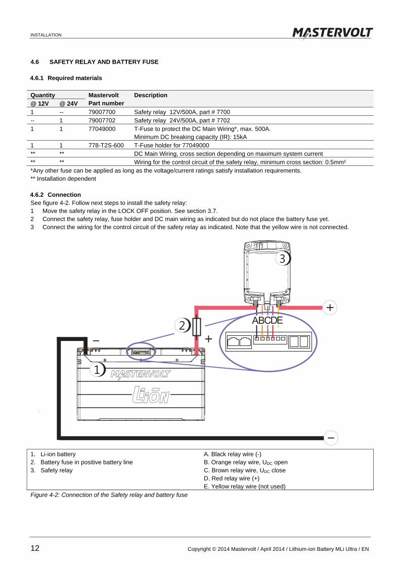
4.6 SAFETY RELAY AND BATTERY FUSE 4.6.1 Required materials
Quantity Mastervolt Part number
Description @ 12V @ 24V 1 -- 79007700 Safety relay 12V/500A, part # 7700 -- 1 79007702 Safety relay 24V/500A, part # 7702 1 1 77049000 T-Fuse to protect the DC Main Wiring*, max. 500A.
Minimum DC breaking capacity (IR): 15kA 1 1 778-T2S-600 T-Fuse holder for 77049000 ** ** DC Main Wiring, cross section depending on maximum system current ** ** Wiring for the control circuit of the safety relay, minimum cross section: 0.5mm² *Any other fuse can be applied as long as the voltage/current ratings satisfy installation requirements. ** Installation dependent 4.6.2 Connection See figure 4-2. Follow next steps to install the safety relay: 1 Move the safety relay in the LOCK OFF position. See section 3.7. 2 Connect the safety relay, fuse holder and DC main wiring as indicated but do not place the battery fuse yet. 3 Connect the wiring for the control circuit of the safety relay as indicated. Note that the yellow wire is not connected.
1. Li-ion battery A. Black relay wire (-) 2. Battery fuse in positive battery line B. Orange relay wire, UDC open 3. Safety relay C. Brown relay wire, UDC close D. Red relay wire (+) E. Yellow relay wire (not used) Figure 4-2: Connection of the Safety relay and battery fuse
+_
1
3
2ECB DA
+
_

INSTALLATION
EN / April 2014 / Lithium-ion Battery MLi Ultra / Copyright © 2014 Mastervolt 13
4.7 CHARGER SETTINGS A single Mastervolt Li-ion battery can be charged with any standard Mastervolt battery charger. These chargers feature the MLi charging option. Without this option, IUoUo charge settings must be as follows: Li-ion battery model
Bulk / absorption voltage setting
Float voltage setting
MLi Ultra 12/2500 14.25 V 13.5 V MLi Ultra 12/5000 14.25 V 13.5 V MLi Ultra 24/5000 28.5 V 27.0 V Refer to the user’s manual of the battery charger for adjustment. The temperature of each cell as well as the temperature of the entire Li-ion battery is monitored by the cell management system. Therefore, do not use a sensor for temperature compensated charging.
Do not use a temperature sensor for temperature compensated charging!
4.8 CHARGING SYSTEMS Installation and configuration of the Stop charge event depend on the system in which the Li-ion battery is used. We describe five ways to charge your Li-ion battery: 1 System with a Mastervolt Mass Charger or
ChargeMaster, refer to section 4.8.1. 2 System with a Mastervolt Alpha Pro II alternator
regulator, refer to section 4.8.2. 3 The Mastervolt Mass Combi, used to charge the
battery. Refer to section 4.8.3 4 Non-Mastervolt charging devices, up to 6A AC. Refer
to section 4.8.4. 5 Non-Mastervolt charging devices, from 6A AC up.
Refer to section 4.8.5. Select one of these options and continue with the
corresponding section.
WARNING If more charging devices are used to charge the Li-ion battery (for instance when the Li-ion battery is charged by both an AC powered charger and an alternator), Stop charge events must be configured for each charging device.
WARNING During the entire installation procedure: The safety relay must remain in LOCK
OFF position The battery fuse should not be placed

INSTALLATION
14 Copyright © 2014 Mastervolt / April 2014 / Lithium-ion Battery MLi Ultra / EN
4.8.1 System with a Mastervolt Mass Charger or ChargeMaster
1. Li-ion battery 5. Loads 2. Battery fuse in positive battery line 6. DC plus cable 3. Safety relay 7. DC minus cable 4 Mastervolt Mass charger or Chargemaster 8. MasterBus cable 9. MasterBus terminator
Figure 4-3: Basic system with a Mastervolt Mass Charger or Chargemaster
Follow next steps to install the Mastervolt Mass Charger or ChargeMaster: 1 Connect the DC main wiring as indicated. 2 Connect the MasterBus cabling between the devices
as indicated. Keep the rules in mind as described in section 6.2.
3 Add a MasterBus control panel to the MasterBus network.
4 Configure the following Stop Charge event at the Li-ion battery:
Configuration Event 1 (obligatory)
Event source Stop charge Event target CHG Mass Charger /
CHG ChargeMaster Event command Float Event data Copy
Stop Charge event The charger must stop charging at the Stop Charge event. The Mass Charger or ChargeMaster is able to process the Stop Charge event. The event source is the Li-ion battery Stop charge. The event target is the Mass Charger or ChargeMaster (CHG Mass Charger or CHG ChargeMaster). At the Stop charge event, the event command “Float” is triggered. The charger switches to float phase and resumes charging the normal way according to its charging characteristic. 5 Continue with chapter 5
6
7
+
8
9
_
1
3
4
52
ECB DA

INSTALLATION
EN / April 2014 / Lithium-ion Battery MLi Ultra / Copyright © 2014 Mastervolt 15
4.8.2 System with Mastervolt Alpha Pro II regulator
1. Li-ion battery 5. Loads 2. Battery fuse in positive battery line 6. DC plus cable 3. Safety relay 7. DC minus cable 4 Alternator with Alpha Pro II regulator 8. MasterBus cable 9. MasterBus terminator Figure 4-4: Basic system with a Mastervolt Alpha Pro II regulator Follow next steps to install the Mastervolt Alpha Pro II regulator: 1 Connect the DC main wiring as indicated. 2 Connect the MasterBus cabling between the devices
as indicated. Keep the rules in mind as described in section 6.2.
3 Add a MasterBus control panel to the MasterBus network.
4 Configure the following Stop Charge event at the Li-ion battery:
Configuration Event 1 (obligatory) Event source Stop Charge Event target APR Alpha Pro MB Event command Suspend charge Event data Copy Stop Charge event The charger must stop charging at the Stop Charge event. The Alpha Pro II regulator is able to process the Stop Charge event. The Event source is the Li-ion battery Stop charge. The Event target is the Alpha Pro II (APR Alpha Pro MB). At the Stop charge event, the Event command
“Suspend charge” is triggered. The charging process of the regulator is interrupted and will resume once the Stop Charge event ends. 5 Configure the following Battery safety event at the Li-
ion battery: Configuration Event 2 (obligatory) Event source Battery Safety Event target APR Alpha Pro MB Event command Suspend charge Event data On Battery safety event If a Battery safety event occurs, the safety relay will disconnect the battery from the electrical installation. This may result in voltage fluctuations on the DC grid and overheating of the field windings of the alternator. Therefore at the Battery Safety event, the Event command “Suspend charge” is triggered which will terminate the charging process. 6 Continue with chapter 5
6
7
+
8
9
_
1
3
52
ECB DA
4

INSTALLATION
16 Copyright © 2014 Mastervolt / April 2014 / Lithium-ion Battery MLi Ultra / EN
4.8.3 System with a Mastervolt Mass Combi
1. Li-ion battery 5. Loads 2. Battery fuse in positive battery line 6. DC plus cable 3. Safety relay 7. DC minus cable 4 MasterBus Combi Interface via serial cable connected to the Mass Combi 8. MasterBus cable 9. MasterBus terminator
Figure 4-5: Basic system with a Mastervolt Mass Combi
Follow next steps to install the Mastervolt Mass Combi: 1 Connect the DC main wiring as indicated. 2 Connect the MasterBus cabling between the devices
as indicated. Keep the rules in mind as described in section 6.2
3 Add a MasterBus control panel to the MasterBus network.
4 Configure the following Stop Charge event at the Li-ion battery:
Configuration Event 1 (obligatory)
Event source Stop Charge Event target INT Mass Combi Event command Charger Event data Copy invert
Stop Charge event The Mass Combi must stop charging at the Stop Charge event. Because the Mass Combi is not MasterBus compatible, it uses the MasterBus-Combi Interface (INT Mass Combi) for MasterBus communication. This interface must be event configured. The Event source is the Li-ion battery Stop charge. The Event target is the MasterBus-Combi Interface with the command Charger Off. After10 minutes the Stop Charge event ends and charging is resumed. 5 Continue with chapter 5
6
7
+
8
9
_
1
3
52
4
ECB DA
INSTALLATION
EN / April 2014 / Lithium-ion Battery MLi Ultra / Copyright © 2014 Mastervolt 17
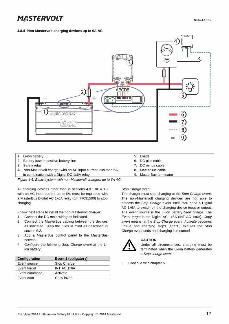
4.8.4 Non-Mastervolt charging devices up to 6A AC
1. Li-ion battery 5. Loads 2. Battery fuse in positive battery line 6. DC plus cable 3. Safety relay 7. DC minus cable 4 Non-Mastervolt charger with an AC input current less than 6A, 8. MasterBus cable in combination with a Digital DC 1x6A relay 9. MasterBus terminator
Figure 4-6: Basic system with non-Mastervolt chargers up to 6A AC.
All charging devices other than in sections 4.8.1 till 4.8.3 with an AC input current up to 6A, must be equipped with a MasterBus Digital AC 1x6A relay (p/n 77031500) to stop charging. Follow next steps to install the non-Mastervolt charger: 1 Connect the DC main wiring as indicated. 2 Connect the MasterBus cabling between the devices
as indicated. Keep the rules in mind as described in section 6.2.
3 Add a MasterBus control panel to the MasterBus network.
4 Configure the following Stop Charge event at the Li-ion battery:
Configuration Event 1 (obligatory)
Event source Stop Charge Event target INT AC 1x6A Event command Activate Event data Copy invert
Stop Charge event The charger must stop charging at the Stop Charge event. The non-Mastervolt charging devices are not able to process the Stop Charge event itself. You need a Digital AC 1x6A to switch off the charging device input or output. The event source is the Li-ion battery Stop charge. The Event target is the Digital AC 1x6A (INT AC 1x6A). Copy invert means, at the Stop Charge event, Activate becomes untrue and charging stops. After10 minutes the Stop Charge event ends and charging is resumed
CAUTION Under all circumstances, charging must be terminated when the Li-ion battery generates a Stop charge event
5 Continue with chapter 5
6
7
+
8
9
_
1
3
52
ECB DA
4

INSTALLATION
18 Copyright © 2014 Mastervolt / April 2014 / Lithium-ion Battery MLi Ultra / EN
4.8.5 Non-Mastervolt charging devices of more than 6A AC
1. Li-ion battery 5. Loads 2. Battery fuse in positive battery line 6. DC plus cable 3. Safety relay 7. DC minus cable 4 Non-Mastervolt charger with an AC input current of more than 6A, 8. MasterBus cable in combination with a Digital DC 1x6A relay controlling another AC relay 9. MasterBus terminator
Figure 4-7: Basic system with non-Mastervolt chargers above 6A AC
All charging devices other than in sections 4.8.1 till 4.8.3 with an AC input current of more than 6A, must be equipped with a digital AC 1x6A relay operating a high current relay to stop charging: Follow next steps to install the non-Mastervolt charger: 1 Connect the DC main wiring as indicated. 2 Connect the MasterBus cabling between the devices
as indicated. Keep the rules in mind as described in section 4.6.
3 Add a MasterBus control panel to the MasterBus network.
4 Configure the following Stop Charge event at the Li-ion battery:
Configuration Event 1 (obligatory)
Event source Stop Charge Event target INT AC 1x6A Event command Activate Event data Copy invert
Stop Charge event The charger must stop charging at the Stop Charge event. The non-Mastervolt charging devices are not able to process the Stop Charge event itself. You need a Digital AC 1x6A to switch off the charging device input or output. The event source is the Li-ion battery Stop charge. The Event target is the Digital AC 1x6A (INT AC 1x6A). Copy invert means, at the Stop Charge event, Activate becomes untrue and charging stops. After10 minutes the Stop Charge event ends and charging is resumed
CAUTION Under all circumstances, charging must be terminated when the Li-ion battery generates a Stop charge event
5 Continue with chapter 5
6
7
+
8
9
_
1
3
52
ECB DA
4

COMMISSIONING
EN / April 2014 / Lithium-ion Battery MLi Ultra / Copyright © 2014 Mastervolt 19
5 COMMISSIONING Follow the steps described below for commissioning of the Li-ion battery 1 Check all wiring and connections; see also the figures
in chapter 4 for wiring details. 2 If everything is OK, move the safety relay in the
“REMOTE OFF” position. See section 3.7. Do not place the fuses yet!
3 On the MasterBus control panel, go to the monitoring
page of the Li-ion battery 4 See figure 5-1. Operate the “Close Relay” button. The
knob on the safety relay should shift inwards. 5 Operate the “Open Relay” button. If the safety relay is
open (Off), the knob position should be outwards. Keep the safety relay in this position.
6 Install all fuses. 7 Switch on some loads 8 On the monitoring page check that the battery current
is 0 Amps. See figure 5-2.
9 Move the safety relay in the REMOTE ON position by pushing the button on top of the safety relay until latched. See section 3.7.
10 Verify that a current is flowing out of the battery (negative current)
11 Switch off the load, switch on the charger and verify
that a current is flowing into the battery (positive value).
12 If necessary, check if the battery is in MasterBus Powering mode. See section 6.3.4 Configuration: MasterBus Power.
13 Depending on the installation in which the Li-ion battery is used, programming of additional MasterBus events may be required. See chapter 6.
14 If necessary, remove the MasterBus control panel from the MasterBus network
15 Charge the Li-ion battery fully until the charger switches to the float stage (maintenance charge) of the charging algorithm
Now the Li-ion battery is ready for operation
Figure 5-1: Buttons for closing and opening the relay
ON
OFF
Figure 5-2: Checking the current

MASTERBUS
20 Copyright © 2014 Mastervolt / April 2014 / Lithium-ion Battery MLi Ultra / EN
6 MASTERBUS 6.1 WHAT IS MASTERBUS?
All devices that are suitable for MasterBus are marked by the MasterBus symbol.
MasterBus is a fully decentralized data network for communication between the different Mastervolt system devices. It is a CAN-bus based communication network which has proven itself as a reliable bus-system in automotive applications. MasterBus is used as power management system for all connected devices, such as the inverter, battery charger, generator and many more. This facilitates communication between the connected devices, for instance to start the generator when the batteries are low. MasterBus reduces complexity of electrical systems by using less cables. All system components are simply chained together. For this purpose every MasterBus device has been equipped with two MasterBus data ports. When two or more devices are connected through these data ports, they become a local data network, called the MasterBus. The results are a reduction of installation costs as only a few electrical cables and less installation time are needed. For central monitoring and control of the connected devices, Mastervolt offers a wide range of panels which show full status information of your electrical system at a glance and a push of a button. Different panels are available, like the MasterView Easy MkII and the full colour MasterView System panel. All monitoring panels can be used for monitoring, control and configuration of all connected MasterBus equipment. New devices can be added to the existing network in a very easy way by just extending the network. This makes the MasterBus a highly flexible network for extended system configuration, today and in the future. Mastervolt also offers several interfaces, making even non-MasterBus devices suitable to operate in the MasterBus network. For direct communication between the MasterBus network and a product which is not from Mastervolt, several interfaces are available. Example is the MasterBus Modbus interface.
CAUTION! Never connect a non-MasterBus device to the MasterBus network directly! This will void warranty of all MasterBus devices connected.
6.2 HOW TO SET UP A MASTERBUS NETWORK Every device that is suitable for the MasterBus network is equipped with two data ports. When two or more devices are connected to each other through these ports, they form a local data network, called the MasterBus. Keep the following rules in mind:
Figure 6-1: UTP patch cable
Figure 6-2: Two Terminators
As with all high speed data networks, MasterBus
needs a terminating device on both ends of the
network.
Terminating
device
Terminating
device
OK
Connections between the devices are made by
standard straight UTP patch cables. Mastervolt can
supply these cables. These cables are also commonly
available at computer supply stores.
OK
1-8

MASTERBUS
EN / April 2014 / Lithium-ion Battery MLi Ultra / Copyright © 2014 Mastervolt 21
Figure 6-3: Power supply
Figure 6-4: No ring networks
Figure 6-5: No T-connections
6.3 MASTERBUS: MONITORING AND CONFIGURATION OF THE LI-ION BATTERY The Li-ion battery can be monitored and configured through the MasterBus network by means of a MasterBus remote control
panel or an interface connected to a PC with MasterAdjust software. The available menu pages are Monitoring, Alarm, History,
Configuration and Events.
6.3.1 Monitoring
Menu Description Adjustable range General State of charge Battery state of charge in % (read only) Remaining Time of battery use left at the actual load in hh:mm:ss (read only) Cap. consumed Battery capacity consumed in Ah (read only) Battery (V) Battery voltage measured by the cell management system (read only) Battery (A) Current measured by the cell management system
Positive value: charging, Negative value: discharging (read only)
Battery (°C) Internal temperature of the battery in °C (read only) Time Actual time in hh:mm:ss (read only) Date Actual date in dd-mm-yyyy (read only) Close relay Button to close the safety relay (switch On) manually to check the
correct operation of the safety relay (see chapter 5). This function should not be used during normal operation.
Open relay Button to open the safety relay (switch Off) manually to check the correct operation of the safety relay (see chapter 5) This function should not be used during normal operation.
Do not make T-connections in the network.
Do not make ring networks. The electric power for the network comes from the
connected devices.
At least one device in the network should have
powering capabilities (see specifications).
One powering device can power up to three non-
powering devices.
As all powering devices are galvanically isolated,
multiple powering devices are allowed.
OK

MASTERBUS
22 Copyright © 2014 Mastervolt / April 2014 / Lithium-ion Battery MLi Ultra / EN
6.3.2 Alarms
Menu Description Adjustable range General Battery safety Toggles on if Battery Safety event occurs; see section 3.3 and
continued On/Off (read only)
Overtemperature The internal temperature of one of the cells is too high. This will also generate a Battery Safety event. ; see section 3.3 and continued.
On/Off (read only)
Overcurrent Battery current is >600A for more than 30 seconds. Reduce load immediately
On/Off (read only)
6.3.3 History
Menu Description Adjustable range Days running Total running time (since first use) in days (read only) Days since low Number of days since last Reduce Discharge event (see section
3.3 and continued) (read only)
Last time 100% Number of days since last 100% State of charge (read only) Battery usage Number of duty cycles the battery has performed (read only) Avg. discharge Average discharge per duty cycle (read only) Total consumed Total kAh that was consumed from the battery since first use (read only) Lowest Ah Deepest discharge since first use (read only) Volt at low Ah Battery voltage measured at deepest discharge (read only) Highest voltage Highest voltage measured since first use (read only)
6.3.4 Configuration
Menu Description Default Adjustable range Device
Language Language setting of the Li-ion battery. NOTE: the language of the display may be different from this setting.
English English, Nederlands
Name Name of your Li-ion battery in the MasterBus system. If you have more than one unit, changing names improves clarity.
Li-ion Any maximum 12 character name
Time hr Time setting of the real time clock: hour 00-23 Time min. Time setting of the real time clock: minutes 00-59 Date Day Time setting of the real time clock: day 01-31 Date Time setting of the real time clock: month January-December Date Yr Time setting of the real time clock: year 2000-2200 Factory settings Option to reset the battery to default settings. If Config. Lock was
checked by the installer, only Language, Name, Time and Date will be reset.
Self test Option to check the operation of the battery management system. Only to be used in consultation with Mastervolt Technical Support.
MasterBus Power On: the Li-ion battery will power the MasterBus network. See section 6.2. Note that this will slowly drain the battery. Off: MasterBus powering disabled.
Off Off, On
Event levels Battery low State of Charge level below which an event can be triggered, see
Events, Battery Low 30% 10-90%
Battery pre low State of Charge level below which an event can be triggered, see Events, Battery pre low
50% 10-90%
Battery full State of Charge level above which an event can be triggered, see Events, Battery full
95% 30-100%
Overvoltage Overvoltage level above which an event can be triggered, see Events, Overvoltage
15.0V / 30.0V
10.0-16.0V / 20.0-32.0V
MASTERBUS
EN / April 2014 / Lithium-ion Battery MLi Ultra / Copyright © 2014 Mastervolt 23
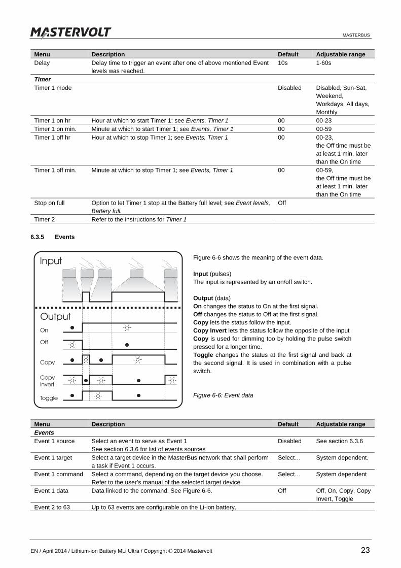
Menu Description Default Adjustable range Delay Delay time to trigger an event after one of above mentioned Event
levels was reached. 10s 1-60s
Timer Timer 1 mode Disabled Disabled, Sun-Sat,
Weekend, Workdays, All days, Monthly
Timer 1 on hr Hour at which to start Timer 1; see Events, Timer 1 00 00-23 Timer 1 on min. Minute at which to start Timer 1; see Events, Timer 1 00 00-59 Timer 1 off hr Hour at which to stop Timer 1; see Events, Timer 1 00 00-23,
the Off time must be at least 1 min. later than the On time
Timer 1 off min. Minute at which to stop Timer 1; see Events, Timer 1 00 00-59, the Off time must be at least 1 min. later than the On time
Stop on full Option to let Timer 1 stop at the Battery full level; see Event levels, Battery full.
Off
Timer 2 Refer to the instructions for Timer 1
6.3.5 Events
Menu Description Default Adjustable range Events Event 1 source Select an event to serve as Event 1
See section 6.3.6 for list of events sources Disabled See section 6.3.6
Event 1 target Select a target device in the MasterBus network that shall perform a task if Event 1 occurs.
Select… System dependent.
Event 1 command Select a command, depending on the target device you choose. Refer to the user’s manual of the selected target device
Select… System dependent
Event 1 data Data linked to the command. See Figure 6-6. Off Off, On, Copy, Copy Invert, Toggle
Event 2 to 63 Up to 63 events are configurable on the Li-ion battery.
Figure 6-6 shows the meaning of the event data. Input (pulses) The input is represented by an on/off switch. Output (data) On changes the status to On at the first signal. Off changes the status to Off at the first signal. Copy lets the status follow the input. Copy Invert lets the status follow the opposite of the input Copy is used for dimming too by holding the pulse switch pressed for a longer time. Toggle changes the status at the first signal and back at the second signal. It is used in combination with a pulse switch. Figure 6-6: Event data

MASTERBUS
24 Copyright © 2014 Mastervolt / April 2014 / Lithium-ion Battery MLi Ultra / EN
6.3.6 List of events sources
Below the list of event sources of the Li-ion battery is shown. These event sources can be used to initiate an event command
and an event action at another device that is connected to the MasterBus.
Event source Condition Comments
Disabled (no event programmed) Battery Safety Battery Safety event occurred. At the same time the
safety relay is triggered to disconnect the battery from the loads and charging devices. See section 3.3.3.
See section 6.4
Reduce charge Battery voltage > 14.5V (12V battery) / > 29.0V (24V battery) or voltage of one of the individual cells is too high or cell temperature is too high.
Reduction of the charge current is recommended.
Reduce discharge Battery voltage < 11.0V (12V battery) / < 22.0V (24V battery) or voltage of one of the individual cells is too low.
Reduction of the discharge current is recommended, for instance by disconnecting non-peripheral loads or switching on additional charging devices.
Stop charge Battery voltage > 15.0V (12V battery) / > 30.0V (24V battery) or voltage of one of the individual cells is too high or cell temperature is too high.
Charging must be stopped immediately. Programming of this event is obligatory, see section 4.8.
Stop discharge Battery voltage < 10.5V (12V battery) / < 21.0V (24V battery) or voltage of one of the individual cells is too low
Discharging must be stopped or additional charging devices must be switched on immediately
Overcurrent. Battery current >600A
Battery current must be reduced immediately
Charging Battery charging current > 1A Indicates that the battery is being charged. Battery pre low State of Charge < Battery pre low See Configuration - Event levels for adjustment
of the Battery pre low threshold level Battery low State of Charge < Battery low See Configuration - Event levels for adjustment
of the Battery low threshold level. Battery full State of Charge > Battery full . See Configuration - Event levels for adjustment
of the Battery full threshold level Overvoltage Battery voltage > Overvoltage for Delay seconds See Configuration - Event levels for adjustment
of the Overvoltage and Delay threshold levels Battery > 20% State of Charge > 19.5 % Battery > 40% State of Charge > 39.5 % Battery > 60% State of Charge > 59.5 % Battery > 80% State of Charge > 79.5 % Battery = 100% State of Charge > 99.5 % Timer 1 Actual time > Timer 1 On and
Actual time < Timer 1 Off and Stop on full is not triggered
See Configuration - Timer for adjustment of the timer settings
Timer 2 Actual time > Timer 2 On and Actual time < Timer 2 Off and Stop on full is not triggered
See Configuration - Timer for adjustment of the timer settings

MASTERBUS
EN / April 2014 / Lithium-ion Battery MLi Ultra / Copyright © 2014 Mastervolt 25
6.3.7 List of list of event commands
Below is shown the list of event commands and event data of the Li-ion battery. Other devices connected to the MasterBus
can be programmed to initiate these commands and actions at the Li-ion battery.
Event command Event data Description
Open relay On The battery safety relay will be opened and remains open until the Close relay
event is triggered
Off No function
Toggle No function
Copy Invert Same as with Event data = “On”, but status follows the opposite of the input
Copy Same as with Event data = “On”
Close relay On The battery safety relay closes and remains closed until the Open relay event is
triggered
Off No function
Toggle No function
Copy Invert Same as with Event data = “On”, but status follows the opposite of the input
Copy Same as with Event data = “On” 6.4 BATTERY SAFETY EVENT THRESHOLD LEVELS There are two kinds of Battery safety events: a resettable and a non-resettable. A resettable safety event occurs if one of the following conditions is met during 30 seconds: The battery voltage is less than 10.0 Volts (12V battery) or 20.0 Volts (24Volt battery); The battery voltage is more than 15.5 Volts (12V battery) or 31.0 Volts (24Volt battery) The voltage of one of the individual cells inside the Li-ion battery is too high or too low The internal temperature of one of the individual cells is too high This event is repeated every 60 seconds. It will only stop repeating if: the battery voltage returns and remains within specifications, i.e. 10.0-15.5V (12V battery) or 20.0-31.0V (24V battery) the battery detects a charge current when the battery voltage was too low; the battery detects a discharge current when the battery voltage was too high. A non-resettable safety event occurs if one of the following conditions is met during 30 seconds: The battery voltage is less than 9.0 Volts (12V battery) or 18.0 Volts (24Volt battery); The battery voltage is more than 16.0 Volts (12V battery) or 32.0 Volts (24Volt battery) The voltage of one of the individual cells inside the Li-ion battery is too high or too low The internal temperature of one of the individual cells is too high
WARNING If a non-resettable Battery safety event occurs, the Li-ion battery is damaged. It shall be secured against further use.

TROUBLE SHOOTING
26 Copyright © 2014 Mastervolt / April 2014 / Lithium-ion Battery MLi Ultra / EN
7 TROUBLE SHOOTING
Failure Possible cause What to do No DC power available
A fuse has blown Check all fuses and replace if necessary A cable or cable connection is defective Check all cables and their connections. Replace if
necessary. A relay has accidentally switched position. Check all relays. The Battery Safety Event has triggered the safety relay to switch off the battery. The battery voltage is too high.
Refer to section 3.3.3
The Battery Safety Event has triggered the safety relay to switch off the battery The battery voltage is too low
Refer to section 3.3.3
The Battery Safety Event has triggered the safety relay to switch off the battery as a result of over temperature alarm.
Refer to section 3.3.3
No DC power available but the battery voltage is within range.
The Battery Safety Event has triggered the safety relay to switch off the battery
Refer to section 3.3.3. If the Battery Safety alarm remains checked for over five minutes while the battery voltage is within range, contact your Mastervolt supplier.
Alarm on the MasterBus display
An alarm is activated. Refer to section 3.4
MasterBus display shows no Li-ion battery
The MasterView Easy has been configured to display selected devices only.
Check the option All devices or select the Li-ion battery to be displayed.
Error in the wiring. Check the MasterBus cables. No terminating device placed at the ends of the network.
MasterBus needs a terminating device on both ends of the network (see section 6.2). Check if available.
MasterBus network is configured as a ring network.
Ring networks are not allowed. Check the connections of the network (section 6.2).

MAINTENANCE, DECOMMISSIONING AND STORAGE
EN / April 2014 / Lithium-ion Battery MLi Ultra / Copyright © 2014 Mastervolt 27
8 MAINTENANCE, DECOMMISSIONING AND STORAGE 8.1 MAINTENANCE No specific maintenance of the Li-ion battery is required. Examine your electrical installation on a regular base, at least once a year. Defects such as loose connections, burnt wiring etc. must be corrected immediately. Keep the battery clean and dry to avoid leakage currents. If necessary, use a soft clean cloth to clean casing of the Li-ion battery. Never use any liquids, acids and/ or scourers. 8.2 TAKING OUT OF OPERATION If it is necessary to take the Li-ion battery out of operation, follow the instructions in order of succession as described below: 1 Disconnect all loads and charging devices. 2 Move the safety relay(s) in the LOCK OFF position
(see section 3.7) 3 Disconnect all wiring Now the Li-ion battery can be demounted in a safe way. 8.3 BATTERY REPLACEMENT
CAUTION If Li-ion batteries need to be replaced individually, make sure that: Before reconnection: the open circuit voltage of these batteries equals the voltage of the replaced or paralleled batteries. After reconnection: MasterBus events need to be reprogrammed for each replaced battery.
8.4 EXCHANGING MASTERBUS DEVICES When exchanging charging devices that are used to charge the Li-ion battery, the event configuration (such as the obligatory Stop Charge event), as well as other settings (such as charge voltage settings) needs to be redone for every new device. 8.5 STORAGE The Li-ion battery should be stored in a dry and well ventilated environment. The rate of self-discharge is less than 4% per month. Elevated environmental temperatures increase the self-discharge rate of the batteries and natural aging. If the Li-ion battery will not be used for a period exceeding 3 months, we advise: If external AC power is available:
o Switch off all loads and switch on the charger. Apply a float voltage as specified in section 4.7
If no external AC power is available,
o Move the safety relay in the LOCK OFF position. See section 3.7.
o Uncheck the MasterBus Power setting (see section 6.3.4)
o Disconnect the MasterBus cables from the Li-ion battery.
o In this setup the batteries can be kept at least 6 months without maintenance.

ORDERING INFORMATION
28 Copyright © 2014 Mastervolt / April 2014 / Lithium-ion Battery MLi Ultra / EN
9 ORDERING INFORMATION
Part number Description 66012500 Li-ion Battery MLi Ultra 12/2500 66015000 Li-ion Battery MLi Ultra 12/5000 66025000 Li-ion Battery MLi Ultra 24/5000 79007700 Safety relay 12V/500A, part # 7700 79007702 Safety relay 24V/500A, part # 7702 77049000 T-Fuse 500A, DC breaking capacity (IR): 15kA 778-T2S-600 T-Fuse holder for 77049000 77031500 Digital AC 1x6A 77010305 MasterView Easy MkII 77010400 MasterView System panel 77030100 MasterBus USB interface, required as interface between your PC and the MasterBus network 77040000 MasterBus terminator for the MasterBus network 77040100 MasterBus connection cable 1,0m / 3.3ft 77040300 MasterBus connection cable 3,0m / 10ft 77040600 MasterBus connection cable 6,0m / 20ft 77041000 MasterBus connection cable 10m / 33ft 77042500 MasterBus connection cable 25m / 82ft 77050100 100m / 330ft MasterBus cable 77050200 50 pcs. MasterBus connectors 77050000 Complete set to assemble MasterBus cables. Delivery includes: 100m / 330ft MasterBus cable, 50 pcs.
modular jacks and crimping tool

TECHNICAL INFORMATION
EN / April 2014 / Lithium-ion Battery MLi Ultra / Copyright © 2014 Mastervolt 29
10 TECHNICAL INFORMATION 10.1 SPECIFICATIONS
Model MLi Ultra 12/2500 MLi Ultra 12/5000 MLi Ultra 24/5000 Article number 66012500 66015000 66025000 Nominal voltage 12 V 12 V 24 V No load voltage, fully charged 13.2 V 13.2 V 26.4 V Nominal capacity (Cn) 180 Ah 360 Ah 180 Ah Nominal energy 2.5 kWh 5 kWh 5 kWh Approximate weight 30 kg (128 lbs) 58 kg (128 lbs) 58 kg (128 lbs) Number of cells 4 8 8 Terminal type Bolts M8 Bolts M8 Bolts M8 Chemistry Lithium iron phosphate Charge/discharge parameters Charge voltage, Bulk/absorption phase**** Minimum 13.75 V
Recommended 14.25 V Maximum 14.6 V
Minimum 13.75 V Recommended 14.25 V Maximum 14.6 V
Minimum: 27.5 V, Recommended 28.5 V Maximum: 29.2 V
Charge voltage, Float phase 13.5V 13.5V 27 V Discharge cut off voltage*** 10V 10V 20 V Recommended charge/ discharge current 60 A 120 A 60 A Maximum charge/ discharge current 500 A 500 A 500 A Required fuse: Max. 500 A. Minimum DC breaking capacity (IR): 15kA Pulse current (10 sec) < 1800 A < 1800 A < 1800 A Rated capacity and cycle life Rated capacity 180 Ah (2.5 kWh) 360 Ah (5 kWh) 180 Ah (5 kWh) Cycle life ~ 2000 @ 80% DOD ~ 2000 @ 80% DOD ~ 2000 @ 80% DOD General Parallel configuration* Yes, unlimited Series configuration* Yes, up to 10 Operating temperature** –25 to 50 ºC / –13 to 122 ºF Nominal operating temperature: 25 ºC / 77 ºF Storage temperature –25 to 50 ºC / –13 to 122 ºFSelf-discharge < 4% per month @ 20 ºC Warranty 2 years Protection degree IP65 Dimensions Length (L) 341±2mm / 22.3±0.1” 622±2mm / 24.5±0.1” 622±2mm / 24.5±0.1” Width (W) 197±2mm / 3.9±0.1” 197±2mm / 7.8±0.1” 197±2mm / 7.8±0.1” Height (H) 355±2mm / 7.0±0.1” 355±2mm / 14.0±0.1” 355±2mm / 14.0±0.1” Installation angle Upright (recommended) or on the long side Interfacing
MasterBus connectivity Yes (see chapter 6) Powering capabilities for MasterBus Yes, selectable (see section6.3.4) External disconnect switch Obligatory, direct connection (see section 4.6) Interconnect balancing multiple batteries Yes, up to 2 equal Li-ion batteries in series* Important available monitoring/events through MasterBus Battery Safety event Preventing unsafe overcharge, overdischarge and overtemperature Stop Charge event Communication to charging devices preventing overcharging
* For systems with more than one single battery, please refer to www.mastervolt.com/batteries. ** Temperatures below 5 ºC/ 41ºF and above 25 ºC/ 77 ºF may affect life time and cycle life. *** Trigger point for battery safety event **** Bulk/absorption phase should be terminated before current accepted by the battery < 0,015xCn

TECHNICAL INFORMATION
30 Copyright © 2014 Mastervolt / April 2014 / Lithium-ion Battery MLi Ultra / EN
10.2 DIMENSIONS
Figure 10-1: Li-ion battery MLi Ultra 12/5000 and MLi Ultra 24/5000 dimensions in mm [inch]
Figure 10-2: Li-ion battery MLi Ultra 12/2500 dimensions in mm [inch]
341 13,41
197 7,75
355
13,98
35
514,0
197 7,8
622 24,5

TECHNICAL INFORMATION
EN / April 2014 / Lithium-ion Battery MLi Ultra / Copyright © 2014 Mastervolt 31
10.3 CHARGE, DISCHARGE CHARACTERISTIC
See figure 10-3. The charge characteristic shows the 3-step charging of the Li-ion battery. The Bulk phase ends if the battery voltage has reached 14.25 / 28.5 V. The absorption phase ends after a preset time since the charge current dropped below 5.0 / 2.5 A (= Return amps). The charge voltage is then lowered to 13.5 (27.0) V (Float) until the Return to Bulk voltage has been reached.
Figure 10-4: Discharge characteristic of the Li-ion battery MLi Ultra 12/5000 (24/5000) See figure 10-4. The Li-ion discharge characteristic shows that the voltage curve more or less remains at the same level for about 80% of the discharging. At the borders of the characteristic the voltage rises and drops very fast.
Figure 10-5: Self discharge characteristic Li-ion battery MLi Ultra 12/5000 (24/5000) versus storage time 10.4 FUSE TO CABLE SIZE For fuses that comply with your cabling cross sections, we refer to ISO 10133:2000.
Figure 10-3: Charge characteristic of Li-ion battery MLi Ultra 12/5000 (24/5000)
14.25 (28.5) V
13.5 (27.0) V
11.0 (22.0) V
360 (180) A
5.0 (2.5) A
0 A
1.0 C
0.5 C
0.3 C
80%
Ah
Self-discharge in relation to the storage temperature
0%
20%
40%
60%
80%
100%
0 2 4 6 8 10 12 14 16 18 20 22 24
Storage in months
%cap
acit
y
20 °C25 °C30 °C40 °C
14.6 (29.2) V
14.0 (28.0) V
12.0 (24.0) V
10.0 (20.0) V

EC DECLARATION OF CONFORMITY
11 EC DECLARATION OF CONFORMITY We, Manufacturer Mastervolt Address Snijdersbergweg 93 1105 AN Amsterdam The Netherlands Declare under our sole responsibility that Product: MLI Ultra Li-ion battery Model: MLI Ultra 12/2500 MLI Ultra 12/5000 MLI Ultra 24/5000 is in conformity with the provisions of the following EC directives: 2006/95/EC (Safety directive); the following harmonized standards have been applied: EN 60950-1:2001+ A11:2004 (LVD) 2004/108/EC (EMC directive); the following harmonized standards have been applied: EN 61000-6-3: 2007 Emission standard for residential, commercial and light-industrial environments EN 61000-6-2: 2005 Immunity for industrial environments 2011/65/EU (RoHS Directive) Amsterdam, 25 January 2012 Mastervolt International B.V. Daan Hobbelen, Product development manager Marine & Mobile
Snijdersbergweg 93, 1105 AN Amsterdam, The Netherlands Tel : + 31-20-3422100 Fax : + 31-20-6971006
Email : [email protected] www.mastervolt.com