Embed Size (px)
Citation preview

MANUAL NO. WR1000-UM-152
USER’S MANUAL

i
INTRODUCTION
INTRODUCTIONTO ENSURE SAFE AND CORRECT USE
INTRODUCTIONINTRODUCTION
ii
INTRODUCTION
INTRODUCTION
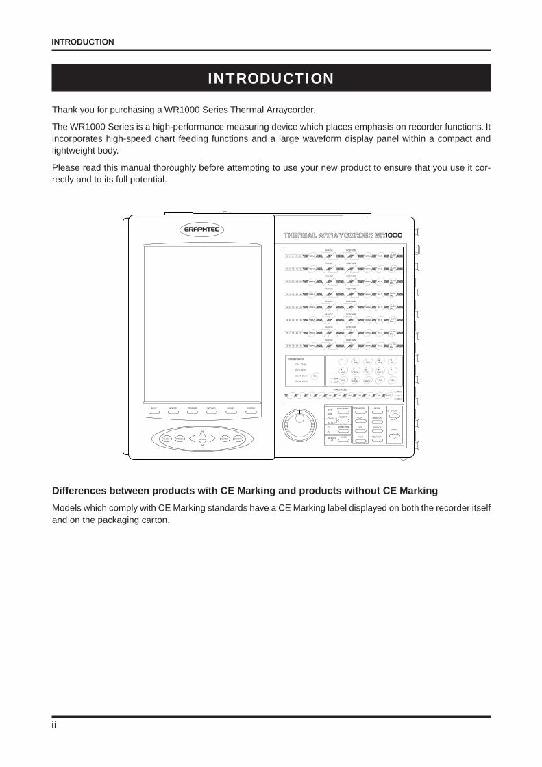
Thank you for purchasing a WR1000 Series Thermal Arraycorder.
The WR1000 Series is a high-performance measuring device which places emphasis on recorder functions. Itincorporates high-speed chart feeding functions and a large waveform display panel within a compact andlightweight body.
Please read this manual thoroughly before attempting to use your new product to ensure that you use it cor-rectly and to its full potential.
Differences between products with CE Marking and products without CE Marking
Models which comply with CE Marking standards have a CE Marking label displayed on both the recorder itselfand on the packaging carton.
iii
INTRODUCTION
Notes on Use
Be sure to read all of the following notes before attempting to use this recorder.
1. Note on the CE Marking
This recorder complies with the EN55022 (1994+A1:1995+A2:1997 Class A) and EN50082-2 (1995-3) stan-dards based on the EMC directive (89/336/EMC). It also conforms to the EN61010-1 (1993/A2:1995) standardbased on the LV directive (72/73/EEC).
Although this recorder complies with the above-mentioned standards, be sure to used it correctly in accordancewith the instructions and notes provided in its User’s Manual.
Moreover, use of this recorder by incorrect procedures may result in damage to the recorder or may invalidateits safeguards. Please confirm all of its notes regarding use and other related information to ensure correct use.
2. Warning
This is a Class A product according to the EMC directive.
In a domestic environment, this product may cause radio interference or may be affected by radio interferenceto the extent that proper measurement cannot be performed.
3. Notes for Safe Operation
(1) Be sure to connect the power cord to an electrical socket with a good protective ground.(2) When a high-voltage signal cable has been connected to the main unit's analog signal input terminal,
avoid touching the leads of the input terminal’s signal cable to prevent electrical shock due to high voltage.(3) Ensure that the recorder’s power source is positioned so that it can easily be disconnected.
4. Notes on Functions and Performance
(1) Be sure to connect the main unit to an AC or DC power supply that conforms to the rated range.Connection to a non-rated power supply may cause the main unit to overheat and break down.
(2) Do not block the vents on the main unit's panels.Continued operation with the vents blocked may cause the main unit to overheat and break down.
(3) To avoid malfunctions and other damage, avoid using this recorder in the following locations.
• Places exposed to high temperature and/or high humidity, such as in direct sunlight or near heatingequipment. (Operating range - Temperature: 0 to 40°C, Humidity: 30 to 80% RH)
• Locations subject to excessive salt spray or heavy fumes from corrosive gas or solvents.• Excessively dusty locations.• Locations subject to strong vibrations or shock.• Locations subject to surge voltages and/or electromagnetic interference.
(4) Use the chart paper supplied by Graphtec. The print quality cannot be guaranteed if other paper types areused.
(5) If the main unit becomes soiled, wipe it off using a soft, dry cloth. Use of organic solvents (such as thinneror benzene) causes deterioration and discoloration of the outer casing.
(6) In the course of use, the thermal head gradually becomes soiled which will lower the print quality.If this happens, it is recommended to clean it using the optional B-368 head cleaner kit. If the print qualitydoes not improve even after using the head cleaner, contact your sales representative or nearest Graphtecvendor.
(7) Do not use the WR1000 in the vicinity of other devices which are susceptible to electromagnetic interfer-ence.
(8) Measured results may not conform to the stated specifications if the WR1000 is used in an environmentwhich is subject to strong electromagnetic interference.
(9) Insofar as possible, position the WR1000 input signal cables away from any other cables which are likelyto be affected by electromagnetic interference.
iv
INTRODUCTION
TO ENSURE SAFE AND CORRECT USE
To ensure safe and correct use of your thermal arraycorder, read this Manual thoroughly before use.
After having read this Manual, keep it in a handy location for quick reference as needed.
Do not permit small children to touch this thermal arraycorder.
The following describes important points for safe operation. Please be sure to observe them strictly.
Conventions Used in This Manua l
To promote safe and accurate use of this thermal arraycorder as well as to prevent human injury and propertydamage, safety precautions provided in this manual are ranked into the five categories described below. Besure you understand the difference between each of the categories.
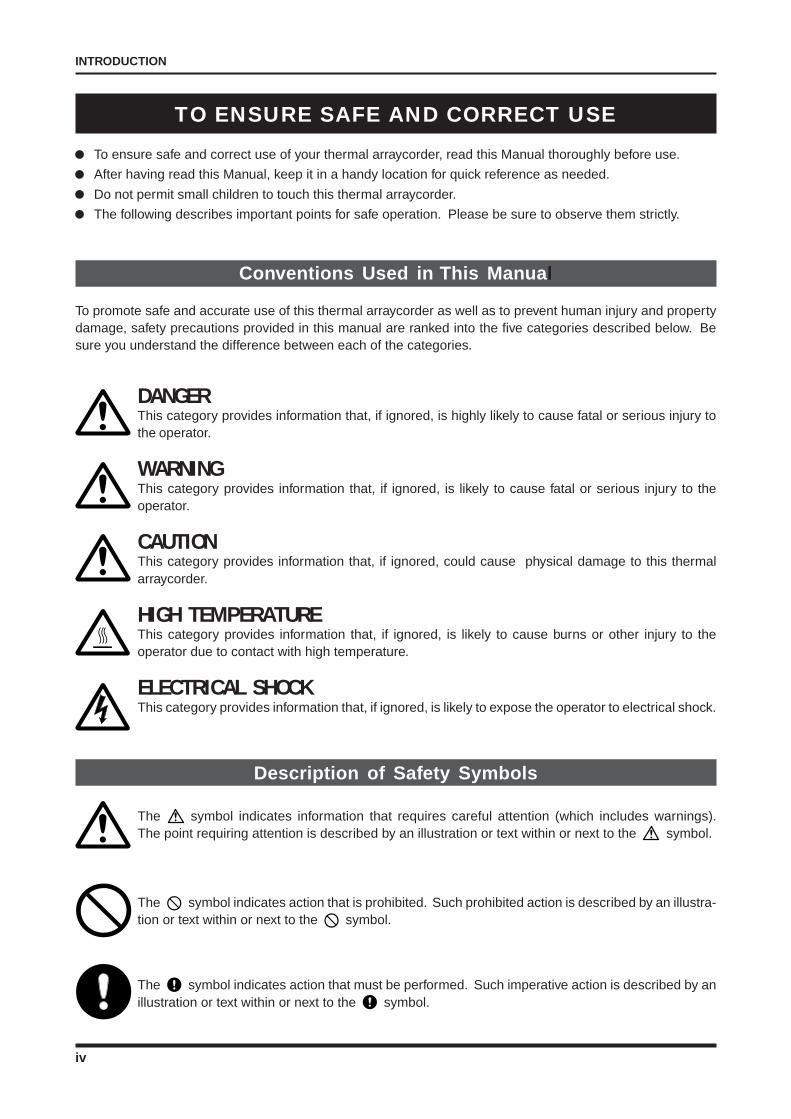
DANGERThis category provides information that, if ignored, is highly likely to cause fatal or serious injury tothe operator.
WARNINGThis category provides information that, if ignored, is likely to cause fatal or serious injury to theoperator.
CAUTIONThis category provides information that, if ignored, could cause physical damage to this thermalarraycorder.
HIGH TEMPERATUREThis category provides information that, if ignored, is likely to cause burns or other injury to theoperator due to contact with high temperature.
ELECTRICAL SHOCKThis category provides information that, if ignored, is likely to expose the operator to electrical shock.
Description of Safety Symbols
The symbol indicates information that requires careful attention (which includes warnings).The point requiring attention is described by an illustration or text within or next to the symbol.
The symbol indicates action that is prohibited. Such prohibited action is described by an illustra-tion or text within or next to the symbol.
The symbol indicates action that must be performed. Such imperative action is described by anillustration or text within or next to the symbol.
v
INTRODUCTION
Safety Precautions
WARNING
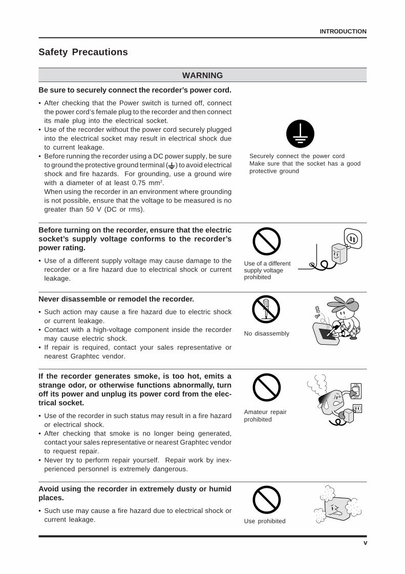
Be sure to securely connect the recorder’s power cord.
• After checking that the Power switch is turned off, connectthe power cord’s female plug to the recorder and then connectits male plug into the electrical socket.
• Use of the recorder without the power cord securely pluggedinto the electrical socket may result in electrical shock dueto current leakage.
• Before running the recorder using a DC power supply, be sureto ground the protective ground terminal ( ) to avoid electricalshock and fire hazards. For grounding, use a ground wirewith a diameter of at least 0.75 mm2.When using the recorder in an environment where groundingis not possible, ensure that the voltage to be measured is nogreater than 50 V (DC or rms).
Before turning on the recorder, ensure that the electricsocket’s supply voltage conforms to the recorder’spower rating.
• Use of a different supply voltage may cause damage to therecorder or a fire hazard due to electrical shock or currentleakage.
Never disassemble or remodel the recorder.
• Such action may cause a fire hazard due to electric shockor current leakage.
• Contact with a high-voltage component inside the recordermay cause electric shock.
• If repair is required, contact your sales representative ornearest Graphtec vendor.
If the recorder generates smoke, is too hot, emits astrange odor, or otherwise functions abnormally, turnoff its power and unplug its power cord from the elec-trical socket.
• Use of the recorder in such status may result in a fire hazardor electrical shock.
• After checking that smoke is no longer being generated,contact your sales representative or nearest Graphtec vendorto request repair.
• Never try to perform repair yourself. Repair work by inex-perienced personnel is extremely dangerous.
Avoid using the recorder in extremely dusty or humidplaces.
• Such use may cause a fire hazard due to electrical shock orcurrent leakage.
Securely connect the power cordMake sure that the socket has a goodprotective ground
QQQQ
¢¢¢¢QQQ¢¢¢
QQQQQ
¢¢¢¢¢
Use of a differentsupply voltageprohibited
No disassembly
Amateur repairprohibited
Use prohibited
vi
INTRODUCTION
Safety Precautions (Continued)
WARNING
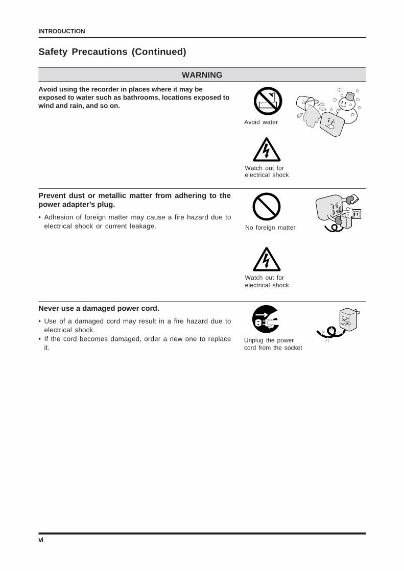
Avoid using the recorder in places where it may beexposed to water such as bathrooms, locations exposed towind and rain, and so on.
Prevent dust or metallic matter from adhering to thepower adapter’s plug.
• Adhesion of foreign matter may cause a fire hazard due toelectrical shock or current leakage.
Never use a damaged power cord.
• Use of a damaged cord may result in a fire hazard due toelectrical shock.
• If the cord becomes damaged, order a new one to replaceit.
Avoid water
Watch out forelectrical shock
Unplug the powercord from the socket
No foreign matter
Watch out forelectrical shock
vii
INTRODUCTION
Safety Precautions (Continued)
CAUTION
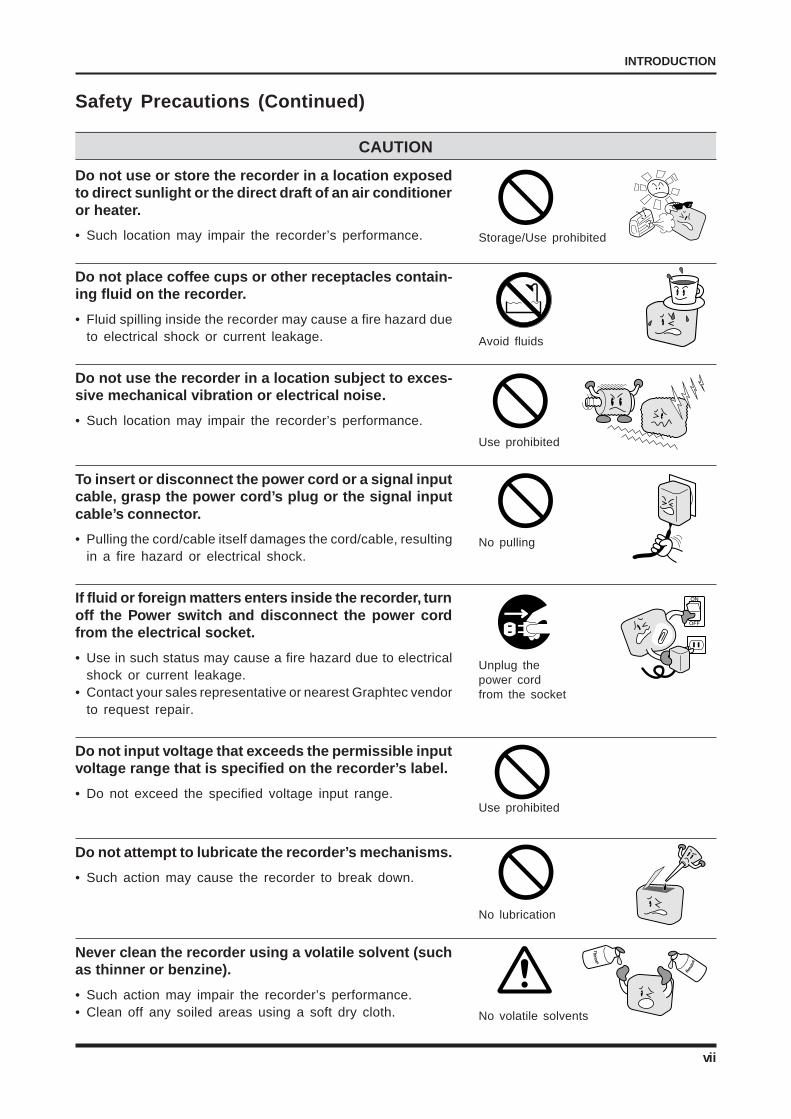
Do not use or store the recorder in a location exposedto direct sunlight or the direct draft of an air conditioneror heater.
• Such location may impair the recorder’s performance.
Do not place coffee cups or other receptacles contain-ing fluid on the recorder.
• Fluid spilling inside the recorder may cause a fire hazard dueto electrical shock or current leakage.
Do not use the recorder in a location subject to exces-sive mechanical vibration or electrical noise.
• Such location may impair the recorder’s performance.
To insert or disconnect the power cord or a signal inputcable, grasp the power cord’s plug or the signal inputcable’s connector.
• Pulling the cord/cable itself damages the cord/cable, resultingin a fire hazard or electrical shock.
If fluid or foreign matters enters inside the recorder, turnoff the Power switch and disconnect the power cordfrom the electrical socket.
• Use in such status may cause a fire hazard due to electricalshock or current leakage.
• Contact your sales representative or nearest Graphtec vendorto request repair.
Do not input voltage that exceeds the permissible inputvoltage range that is specified on the recorder’s label.
• Do not exceed the specified voltage input range.
Do not attempt to lubricate the recorder’s mechanisms.
• Such action may cause the recorder to break down.
Never clean the recorder using a volatile solvent (suchas thinner or benzine).
• Such action may impair the recorder’s performance.• Clean off any soiled areas using a soft dry cloth.
Use prohibited
No pulling
Unplug thepower cordfrom the socket
Use prohibited
No lubrication
Storage/Use prohibited
Avoid fluids
No volatile solvents
Th
inne
r
Benzi
ne
viii
CONTENTS
CONTENTS
INTRODUCTION .......................................................................................................................................... iNotes on Use ........................................................................................................................................... iii
TO ENSURE SAFE AND CORRECT USE ........................................................................................ iv
Conventions Used in This Manual ............................................................................................................ iv
Description of Safety Symbols ................................................................................................................. iv
Safety Precautions .................................................................................................................................... vWARNING...................................................................................................................................... vCAUTION ..................................................................................................................................... vii
1. GENERAL DESCRIPTION .......................................................................................................... 1-1
1.1 Overview .................................................................................................................................... 1-2
1.2 Features ..................................................................................................................................... 1-2
1.3 Unpacking Your Recorder .......................................................................................................... 1-3
2. DESCRIPTION OF THE MAIN UNIT’S PARTS ..................................................................... 2-1
2.1 The Front Panel ......................................................................................................................... 2-22.1.1 The Display Monitor ....................................................................................................... 2-32.1.2 The Amp Control Panel ................................................................................................. 2-42.1.3 The Numeric Keypad and CHART SPEED Section ...................................................... 2-62.1.4 The Main Control Panel ................................................................................................. 2-72.1.5 The Conditions Panel .................................................................................................... 2-9
2.2 The Top Panel .......................................................................................................................... 2-10
2.3 The Left Panel ......................................................................................................................... 2-11
2.4 The Right Panel ....................................................................................................................... 2-12
2.5 The Amp Units ......................................................................................................................... 2-132.5.1 The V Type Amp .......................................................................................................... 2-132.5.2 The M Type Amp.......................................................................................................... 2-142.5.3 The Logic Amp ............................................................................................................ 2-15
3. PREPARATIONS ............................................................................................................................ 3-1
3.1 The Working Environment ......................................................................................................... 3-23.1.1 Choosing an Installation Site ......................................................................................... 3-23.1.2 Positioning the Recorder for Use ................................................................................... 3-2
3.2 Notes on the Liquid Crystal Display Panel ................................................................................. 3-3
3.3 Installing or Removing an Amp .................................................................................................. 3-43.3.1 Installing an Analog Amp ............................................................................................... 3-43.3.2 Installing a Logic Amp ................................................................................................... 3-6
3.4 Installing or Removing the SCSI or GP-IB Interface Board ....................................................... 3-73.4.1 Installing the SCSI or GP-IB Interface Board ................................................................ 3-7
3.5 Connecting the Signal Input Cables ........................................................................................ 3-113.5.1 Connection to the V (Voltage) Amp ............................................................................. 3-113.5.2 Connection to the M (Voltage & Temperature) Amp .................................................... 3-123.5.3 Connecting the Logic Cable to a Logic Amp ............................................................... 3-13
3.6 Connecting the Recorder to a Power Supply ........................................................................... 3-143.6.1 Connecting to an AC Power Supply ............................................................................ 3-143.6.2 Connecting to a DC Power Supply .............................................................................. 3-15
ix
CONTENTS
3.7 Loading Chart Paper ................................................................................................................ 3-183.7.1 Loading Roll Paper ...................................................................................................... 3-183.7.2 Mounting the Internal Z-Fold Unit ................................................................................ 3-203.7.3 Loading Z-Fold Paper in the Long-Length Z-Fold Unit ................................................ 3-22
3.8 Attaching the Writing Table ...................................................................................................... 3-26
3.9 Changing the Display Language .............................................................................................. 3-27
3.10 Momentary Interruption of the AC Power Supply ..................................................................... 3-27
3.11 Protecting the Thermal Printhead ............................................................................................ 3-27
3.12 Notes on Temperature Measurement ...................................................................................... 3-27
4. DESCRIPTION OF MENUS ........................................................................................................ 4-1
4.1 Structure of the Menus .............................................................................................................. 4-2
4.2 The Input Menu.......................................................................................................................... 4-34.2.1 The Input Menu’s Tree Structure.................................................................................... 4-34.2.2 The AMP. SETTINGS Window ....................................................................................... 4-34.2.3 The ENGINEERING UNIT SETTINGS Window ............................................................ 4-8
4.3 The Memory Menu .................................................................................................................. 4-114.3.1 The Memory Menu’s Tree Structure ............................................................................ 4-114.3.2 The MEMORY SETTINGS Window ............................................................................. 4-124.3.3 The REPLAY SETTINGS Window ............................................................................... 4-194.3.4 The CALCULATION SETTINGS Window .................................................................... 4-214.3.5 The READOUT SETTINGS Window ........................................................................... 4-23
4.4 The Trigger Menu ..................................................................................................................... 4-304.4.1 The Trigger Menu’s Tree Structure ............................................................................... 4-304.4.2 The TRIGGER SETTINGS Window............................................................................. 4-314.4.3 Possible Combinations of Source Settings .................................................................. 4-42
4.5 The Record Menu .................................................................................................................... 4-434.5.1 The Record Menu’s Tree Structure .............................................................................. 4-434.5.2 The RECORD SETTINGS Window ............................................................................. 4-444.5.3 The FORMAT SETTINGS Window .............................................................................. 4-504.5.4 The ANNOTATION SETTINGS Window ...................................................................... 4-56
4.6 The JUDGE Menu ................................................................................................................... 4-584.6.1 The JUDGE Menu’s Tree Structure ................................................................................ 4-584.6.2 The Judgement Settings (Direct) Window ................................................................... 4-594.6.3 The Judgement Settings (Memory) Window ............................................................... 4-60
4.7 The System Menu.................................................................................................................... 4-624.7.1 The System Menu’s Tree Structure.............................................................................. 4-624.7.2 The SYSTEM SETTINGS Window .............................................................................. 4-634.7.3 The OPTION SETTINGS Window ............................................................................... 4-674.7.4 The CUSTOMIZE SETTINGS Window ........................................................................ 4-704.7.5 The TESTS Window .................................................................................................... 4-71
4.8 The EXECUTE Menu ............................................................................................................... 4-734.8.1 Tree Structure of the EXECUTE Menu ........................................................................ 4-734.8.2 The EXECUTE Menu Display ...................................................................................... 4-74
5. SIMPLIFIED RECORDING IN REALTIME .............................................................................. 5-1
5.1 Overall Flow of the Setting Procedure ....................................................................................... 5-2
5.2 Enabling Simplified Direct Recording ........................................................................................ 5-3
x
CONTENTS
6. FLOW OF SETTING OPERATIONS ......................................................................................... 6-1
6.1 Flow of Setting Operations ........................................................................................................ 6-2
7. SETTING THE AMP FUNCTIONS ............................................................................................. 7-1
7.1 Opening the AMP SETTINGS Window ...................................................................................... 7-2
7.2 Selecting the Input Coupling (MEAS.) Type ............................................................................... 7-2
7.3 Setting the Measurement RANGE ............................................................................................. 7-3
7.4 Selecting the FILTER Mode ....................................................................................................... 7-3
7.5 Setting the Measurement SPAN ................................................................................................ 7-4
7.6 Setting the Logic Amp’s Conditions ........................................................................................... 7-6
7.7 Setting the VERNIER Function .................................................................................................. 7-7
8. RECORDING IN REALTIME ....................................................................................................... 8-1
8.1 Overview of DIRECT Recording ................................................................................................ 8-2
8.2 Enabling DIRECT Y-T Recording ............................................................................................... 8-3
8.3 Enabling DIRECT X-Y Recording .............................................................................................. 8-5
8.4 Enabling DIRECT Logging ......................................................................................................... 8-7
9. SAVING DATA IN REALTIME ..................................................................................................... 9-1
9.1 Overview of DIRECT SAVE Operations..................................................................................... 9-2
9.2 Enabling DIRECT Y-T SAVE Operations.................................................................................... 9-4
9.3 Enabling DIRECT X-Y SAVE Operations................................................................................... 9-7
9.4 Enabling DIRECT LOGGING SAVE Operations ...................................................................... 9-10
10. CAPTURING DATA IN A MEMORY DEVICE ....................................................................... 10-1
10.1 Overview of MEMORY SAVE Operations ................................................................................ 10-2
10.2 Enabling MEMORY Y-T SAVE Operations ............................................................................... 10-3
10.3 Enabling MEMORY X-Y SAVE Operations .............................................................................. 10-6
11. USING THE SCALING FUNCTIONS ...................................................................................... 11-1
11.1 Scaling the Upper and Lower Limits of the Signal Input .......................................................... 11-2
11.2 Offsetting the Input Values ....................................................................................................... 11-7
12. USING THE MEMORY FUNCTIONS ...................................................................................... 12-1
12.1 Setting Procedures for Capturing Data .................................................................................... 12-212.1.1 Saving Data to the Recorder’s Internal Memory .......................................................... 12-212.1.2 Automatically Backing Up Data Captured in the Recorder’s Internal Memory to Disk .. 12-512.1.3 Saving Data to a Disk .................................................................................................. 12-612.1.4 Performing Statistical Calculation on Data Captured in Internal Memory.................... 12-9
12.2 Setting Procedures for Replaying Data.................................................................................. 12-1112.2.1 Replaying Captured Data .......................................................................................... 12-1112.2.2 Replaying the Data of All Channels or Only the Specified Channel .......................... 12-1312.2.3 Expanding/Compressing the Time Axis for Replaying Captured Data ...................... 12-1412.2.4 Saving Data Captured in the Recorder’s Internal Memory to Disk ............................ 12-15
12.3 Searching for Memory Data ................................................................................................... 12-1612.3.1 Searching for a Position of the Specified Voltage Level ............................................. 12-1612.3.2 Searching for an Event Marker .................................................................................. 12-18
xi
CONTENTS
12.4 Outputting Data Being Replayed onto Chart Paper ............................................................... 12-19
12.5 Expanding or Compressing the Display of Data Being Replayed .......................................... 12-20
12.6 Performing a Calculation Operation on a Cursor-Defined Range of Captured Data ............. 12-22
12.7 Performing Area Statistical Calculation on a Cursor-Defined Range of Captured Data ........ 12-27
13. USING THE TRIGGER FUNCTIONS ...................................................................................... 13-1
13.1 Disabling the Trigger Function ................................................................................................. 13-2
13.2 Activating the Trigger by the TRIGGER Key ............................................................................ 13-2
13.3 Activating the Trigger by an Externally-Supplied REMOTE Signal .......................................... 13-3
13.4 Activating the Trigger by the Signal Input’s Voltage Level ........................................................ 13-413.4.1 Starting/Stopping Measurement When the Trigger Condition
of One Channel Is Met................................................................................................. 13-413.4.2 Starting/Stopping Measurement When the Trigger Condition
of Every Channel Is Met .............................................................................................. 13-7
13.5 Activating the Trigger by the Slope of the Signal Input’s Rise (Fall) Time .............................. 13-11
13.6 Arming the Trigger Only within the Specified Time Interval ................................................... 13-13
13.7 Starting Measurement Before (After) the Trigger Is Activated ............................................... 13-15
13.8 Stopping Measurement at a Specified Time Interval After the Trigger is Activated ............... 13-16
13.9 Starting/Stopping Measurement After the Trigger Is Activated the Specified Numberof Times ................................................................................................................................. 13-17
13.10 Filtering the Trigger ................................................................................................................ 13-18
14. USING THE RECORDING FUNCTIONS ............................................................................... 14-1
14.1 Various Settings Related to Display and Recording in RECORDER Mode(Display Mode Setting: Y-T) ...................................................................................................... 14-214.1.1 Changing the Waveform Display Mode of Signal Input to Y-T...................................... 14-214.1.2 Changing the Output Destination of Signal Input ........................................................ 14-214.1.3 Outputting Captured Data onto Chart Paper ............................................................... 14-214.1.4 Selecting a Predetermined Chart Speed Setting ........................................................ 14-314.1.5 Specifying a User-Defined Chart Speed Setting ......................................................... 14-314.1.6 Printing Channel ID Nos. on Waveforms ..................................................................... 14-414.1.7 Printing Timing Markers or Event Markers .................................................................. 14-514.1.8 Printing a Scale on Chart Paper .................................................................................. 14-614.1.9 Printing a List of Current Settings ................................................................................ 14-614.1.10 Changing the Record Format and Zone Settings ..................................................... 14-714.1.11 Changing the Grid Setting ........................................................................................ 14-814.1.12 Enabling the Envelope Function ............................................................................... 14-914.1.13 Prioritizing Display of a Specific Channel ................................................................. 14-914.1.14 Changing the Color of Waveform Display ............................................................... 14-1014.1.15 Changing the Line Width of Waveforms ................................................................. 14-1114.1.16 Printing a Reference Line in Each Zone ................................................................. 14-1114.1.17 Changing the Print Interval between Annotations .................................................. 14-1214.1.18 Selecting the No. of Characters in Annotation ........................................................ 14-1314.1.19 Selecting the Method for the Control of Annotation Printing .................................. 14-1314.1.20 Printing a Title at the Top of the Chart Paper .......................................................... 14-1414.1.21 Printing a Message or Measured Values for Each Channel ................................... 14-15
14.2 Various Settings Related to Display and Recording in RECORDER Mode(Display Mode Setting: X-Y) ................................................................................................... 14-1614.2.1 Changing the Waveform Display Mode of Signal Input to X-Y .................................. 14-1614.2.2 Changing the Output Destination of Signal Input ...................................................... 14-16
xii
CONTENTS
14.2.3 Printing a List of Current Settings .............................................................................. 14-1614.2.4 Changing the Grid Setting ......................................................................................... 14-1714.2.5 Selecting the Compensation Mode............................................................................ 14-1714.2.6 Selecting the Plot On/Off Status for Each XY Number .............................................. 14-1714.2.7 Changing the Color of Waveform Display .................................................................. 14-1814.2.8 Selecting the X-Axis and Y-Axis Channels ................................................................. 14-19
14.3 Recording and Display in LOGGING Mode ........................................................................... 14-2014.3.1 Changing the Logging Interval .................................................................................. 14-2014.3.2 Printing a List of the Current Settings ........................................................................ 14-2014.3.3 Changing the Number of Displayed Zones ................................................................ 14-2014.3.4 Assigning a Channel to a Display Zone ..................................................................... 14-2114.3.5 Changing the Text Color of Each Zone ...................................................................... 14-21
15. SETTING THE WAVEFORM JUDGEMENT FUNCTIONS ............................................... 15-1
15.1 Performing a Waveform Judgement Operation during DIRECT Measurement ....................... 15-2
15.2 Performing a Waveform Judgement Operation during MEMORY Measurement ..................... 15-4
16. PERFORMING DISK OPERATIONS ...................................................................................... 16-1
16.1 Saving Your Settings ................................................................................................................ 16-2
16.2 Loading Your Settings .............................................................................................................. 16-2
16.3 Displaying Information about a File ......................................................................................... 16-3
16.4 Copying a File or Folder ........................................................................................................... 16-4
16.5 Renaming a File or Folder ....................................................................................................... 16-5
16.6 Deleting a File or Folder .......................................................................................................... 16-6
16.7 Reformatting a Hard Disk ........................................................................................................ 16-7
16.8 Formatting a Disk..................................................................................................................... 16-8
16.9 Listing the Recorder’s Existing Drives ................................................................................... 16-10
17. SETTING THE INTERFACE FUNCTIONS ............................................................................ 17-1
17.1 Selecting the Interface Type ..................................................................................................... 17-2
17.2 Selecting the New Line Code .................................................................................................. 17-2
17.3 Setting the RS-232C Interface Conditions ............................................................................... 17-317.3.1 Selecting the Transfer Speed ....................................................................................... 17-317.3.2 Selecting the Length of the DATA Byte ........................................................................ 17-317.3.3 Selecting the Number of Stop Bits............................................................................... 17-417.3.4 Selecting the Parity Mode ............................................................................................ 17-417.3.5 Selecting the Handshaking (Flow Cont) Mode ............................................................ 17-517.3.6 Selecting the Time Out Interval ................................................................................... 17-5
17.4 Setting the GP-IB Interface Conditions .................................................................................... 17-617.4.1 Selecting the Recorder’s Device Address ................................................................... 17-617.4.2 Selecting the Terminator Code .................................................................................... 17-617.4.3 Selecting the Time Out Interval ................................................................................... 17-7
18. USING THE BASIC FUNCTIONS ............................................................................................ 18-1
18.1 Locking the Panel Keys............................................................................................................ 18-2
18.2 Returning the Settings to Their Factory Default Settings ......................................................... 18-2
18.3 Adjusting the Backlit Display’s Brightness ............................................................................... 18-2
18.4 Using the Screen Saver ........................................................................................................... 18-3
xiii
CONTENTS
18.5 Starting Measurement/Printing When the Power is Turned On................................................ 18-3
18.6 Using the Beeper and Adjusting Its Volume ............................................................................. 18-4
18.7 Enabling the Key Click Sound .................................................................................................. 18-5
18.8 Changing the Date and Time ................................................................................................... 18-5
18.9 Changing the Displayed Language .......................................................................................... 18-6
18.10 Using the Long-Length Chart Unit ........................................................................................... 18-6
18.11 Making a Copy of the Screen Display ...................................................................................... 18-7
19. INPUTTING ALPHANUMERIC CHARACTERS ................................................................. 19-1
19.1 Using the Numeric Keypad for Alphanumeric Input ................................................................. 19-219.1.1 Key Assignment of the Numeric Keypad ..................................................................... 19-219.1.2 Numeric Example: Inputting SPAN Values................................................................... 19-319.1.3 Alphabetic Example: Inputting a Title Character String ............................................... 19-5
19.2 Using the Arrow Keys and Jog/Shuttle Dial for Alphanumeric Input ........................................ 19-619.2.1 Numeric Example: Inputting SPAN Values................................................................... 19-619.2.2 Alphabetic Example: Inputting a Title Character String ............................................... 19-8
20. PERFORMING CURSOR OPERATIONS ............................................................................. 20-1
20.1 Overview of Cursor Functions ................................................................................................. 20-220.1.1 Types of Cursor Functions ........................................................................................... 20-2
20.2 The Cursor Display .................................................................................................................. 20-320.2.1 When the Display Mode Setting is Y-T ......................................................................... 20-320.2.2 When the Display Mode Setting is X-Y ........................................................................ 20-3
20.3 The Display Position of Cursor Information ............................................................................. 20-420.3.1 When the Display Mode Setting is Y-T ......................................................................... 20-420.3.2 When the Display Mode Setting is X-Y ........................................................................ 20-5
20.4 Using the Cursor-Controlled Scroll Function ........................................................................... 20-6
20.5 Using the Cursor Readout Function ........................................................................................ 20-6
20.6 Expanding/Compressing the Cursor-Defined Range of the Waveform Displayto the Screen’s Width ............................................................................................................... 20-7
20.7 Printing Data within a Cursor-Defined Range .......................................................................... 20-8
20.8 Saving a Cursor-Defined Range of Data to Disk ..................................................................... 20-9
20.9 Saving the Cursor Position .................................................................................................... 20-10
20.10 Loading a Cursor Position...................................................................................................... 20-11
20.11 Other Cursor Functions ......................................................................................................... 20-1220.11.1 Moving to the Beginning of Replay Data ................................................................ 20-1220.11.2 Moving to the End of Replay Data .......................................................................... 20-1220.11.3 Moving to a Cursor-Defined Position (within Replay Data) ..................................... 20-1320.11.4 Moving the Cursor to a Selected Time (within Replay Data) .................................. 20-1520.11.5 Summoning the Other Cursor ................................................................................ 20-16
21. PERFORMING FILE OPERATIONS ....................................................................................... 21-1
21.1 Managing Files ........................................................................................................................ 21-221.1.1 Elements of File Management ..................................................................................... 21-221.1.2 File Types ..................................................................................................................... 21-2
21.2 Designating an Existing Drive .................................................................................................. 21-3
21.3 Designating an Existing Folder ................................................................................................ 21-4
21.4 Moving to an Existing Folder.................................................................................................... 21-5
xiv
CONTENTS
21.5 Creating a New Folder ............................................................................................................. 21-6
21.6 Designating an Existing File .................................................................................................... 21-8
21.7 Creating a New File ................................................................................................................. 21-9
21.8 Using the Auto Save Function ............................................................................................... 21-11
22. USING THE REMOTE CONNECTOR ..................................................................................... 22-1
22.1 The REMOTE Connector’s Functions and Pin Assignment ..................................................... 22-2
22.2 Assembling the REMOTE Connector ...................................................................................... 22-4
22.3 Using the REMOTE Functions ................................................................................................. 22-5
APPENDIX A. SPECIFICATIONS .................................................................................................... A-1
A.1 Basic Specifications ................................................................................................................... A-2
A.2 Memory Functions ..................................................................................................................... A-3
A.3 Trigger Functions ....................................................................................................................... A-4
A.4 Measurement Mode Functions .................................................................................................. A-5
A.5 Plug-in Amplifiers ....................................................................................................................... A-6A.5.1 V (Voltage Input) Type Amp ........................................................................................... A-6A.5.2 M (Multi-Input) Type Amp............................................................................................... A-7A.5.3 LO (Logic) Type Amp ..................................................................................................... A-8
A.6 Memory Devices ........................................................................................................................ A-9A.6.1 Floppy Disk Drive .......................................................................................................... A-9A.6.2 MO (Magneto-Optic) Disk Drive (Factory-Installed Unit) ............................................... A-9A.6.3 Hard Disk (Factory-Installed Unit) ................................................................................. A-9
A.7 Interface Units .......................................................................................................................... A-10A.7.1 RS-232C Interface ....................................................................................................... A-10A.7.2 GB-IB Interface ............................................................................................................ A-10A.7.3 SCSI Interface Unit (Factory-Installed Unit) ................................................................. A-10
A.8 DC Adapter Unit (Factory-Installed Unit) ................................................................................. A-11
APPENDIX B. SUPPLIES, ADD-ON UNITS, AND OTHER ACCESSORIES .................... B-1
B.1 Supplies Designation ................................................................................................................. B-2
B.2 Add-on Units Designation .......................................................................................................... B-2
B.3 Other Accessories ..................................................................................................................... B-2
APPENDIX C. MAINTAINING THE RECORDER ........................................................................ C-1
C.1 Cleaning the Thermal Printhead ................................................................................................ C-2
C.2 If an MO Disk Gets Jammed in its Drive .................................................................................... C-2
APPENDIX D. BEFORE REQUESTING SERVICE .................................................................... D-1
D.1 BEFORE REQUESTING SERVICE........................................................................................... D-2
APPENDIX E. EXTERNAL DIMENSIONS .................................................................................... E-1
E.1 External Dimensions of the Standard Model (16 Channels) ...................................................... E-2
E.2 External Dimensions of the Standard Model with Writing TableAttached (16 Channels) ............................................................................................................. E-3
1 – 1
1. GENERAL DESCRIPTION
GENERAL DESCRIPTION
This chapter provides a general description of theWR1000 and its features. It also explains how to checkthe recorder’s external casing and its standard accesso-ries after you unpack your recorder.
1.1 Overview1.2 Features1.3 Unpacking Your Recorder
CHAPTER 1CHAPTER 1
1 – 2
1. GENERAL DESCRIPTION
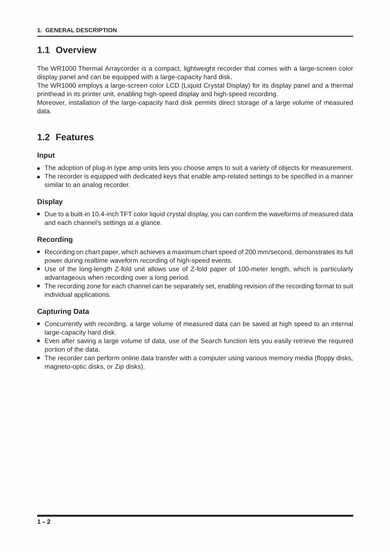
1.1 Overview
The WR1000 Thermal Arraycorder is a compact, lightweight recorder that comes with a large-screen colordisplay panel and can be equipped with a large-capacity hard disk.The WR1000 employs a large-screen color LCD (Liquid Crystal Display) for its display panel and a thermalprinthead in its printer unit, enabling high-speed display and high-speed recording.Moreover, installation of the large-capacity hard disk permits direct storage of a large volume of measureddata.
1.2 Features
Input
The adoption of plug-in type amp units lets you choose amps to suit a variety of objects for measurement.The recorder is equipped with dedicated keys that enable amp-related settings to be specified in a mannersimilar to an analog recorder.
Display
Due to a built-in 10.4-inch TFT color liquid crystal display, you can confirm the waveforms of measured dataand each channel’s settings at a glance.
Recording
Recording on chart paper, which achieves a maximum chart speed of 200 mm/second, demonstrates its fullpower during realtime waveform recording of high-speed events.Use of the long-length Z-fold unit allows use of Z-fold paper of 100-meter length, which is particularlyadvantageous when recording over a long period.The recording zone for each channel can be separately set, enabling revision of the recording format to suitindividual applications.
Capturing Data
Concurrently with recording, a large volume of measured data can be saved at high speed to an internallarge-capacity hard disk.Even after saving a large volume of data, use of the Search function lets you easily retrieve the requiredportion of the data.The recorder can perform online data transfer with a computer using various memory media (floppy disks,magneto-optic disks, or Zip disks).
1 – 3
1. GENERAL DESCRIPTION
1.3 Unpacking Your Recorder
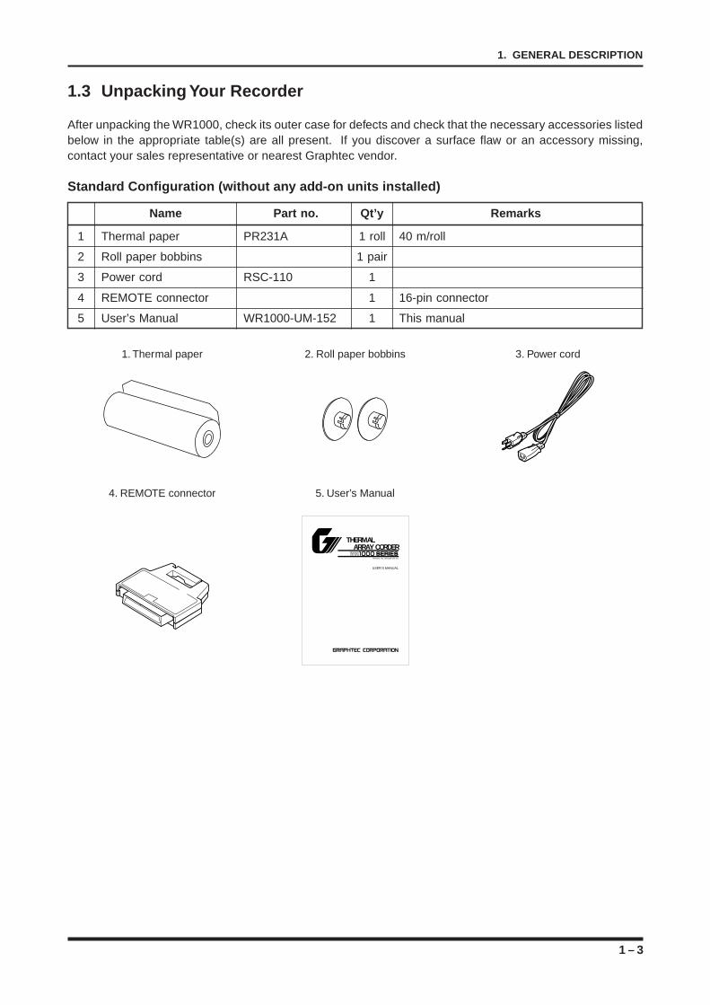
After unpacking the WR1000, check its outer case for defects and check that the necessary accessories listedbelow in the appropriate table(s) are all present. If you discover a surface flaw or an accessory missing,contact your sales representative or nearest Graphtec vendor.
Standard Configuration (without any add-on units installed)
Name Part no. Qt’y Remarks
1 Thermal paper PR231A 1 roll 40 m/roll
2 Roll paper bobbins 1 pair
3 Power cord RSC-110 1
4 REMOTE connector 1 16-pin connector
5 User’s Manual WR1000-UM-152 1 This manual
1. Thermal paper 2. Roll paper bobbins 3. Power cord
4. REMOTE connector 5. User’s Manual
1THERMAL ARRAY CORDER WR1000 series
MANUAL NO. WR1000-UM-151
USER’S MANUAL
1 – 4
1. GENERAL DESCRIPTION
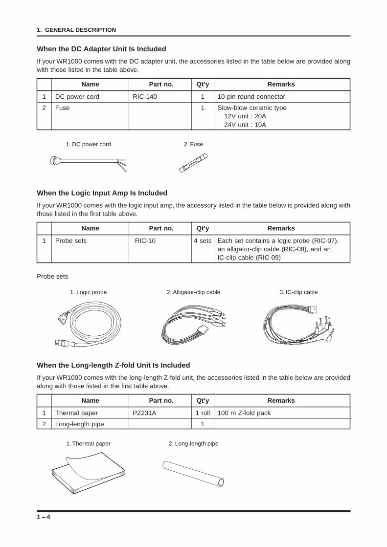
When the DC Adapter Unit Is Included
If your WR1000 comes with the DC adapter unit, the accessories listed in the table below are provided alongwith those listed in the table above.
Name Part no. Qt’y Remarks
1 DC power cord RIC-140 1 10-pin round connector
2 Fuse 1 Slow-blow ceramic type12V unit : 20A24V unit : 10A
1. DC power cord 2. Fuse
When the Logic Input Amp Is Included
If your WR1000 comes with the logic input amp, the accessory listed in the table below is provided along withthose listed in the first table above.
Name Part no. Qt’y Remarks
1 Probe sets RIC-10 4 sets Each set contains a logic probe (RIC-07),an alligator-clip cable (RIC-08), and anIC-clip cable (RIC-09)
Probe sets
1. Logic probe 2. Alligator-clip cable 3. IC-clip cable
When the Long-length Z-fold Unit Is Included
If your WR1000 comes with the long-length Z-fold unit, the accessories listed in the table below are providedalong with those listed in the first table above.
Name Part no. Qt’y Remarks
1 Thermal paper PZ231A 1 roll 100 m Z-fold pack
2 Long-length pipe 1
1. Thermal paper 2. Long-length pipe
1 – 5
1. GENERAL DESCRIPTION
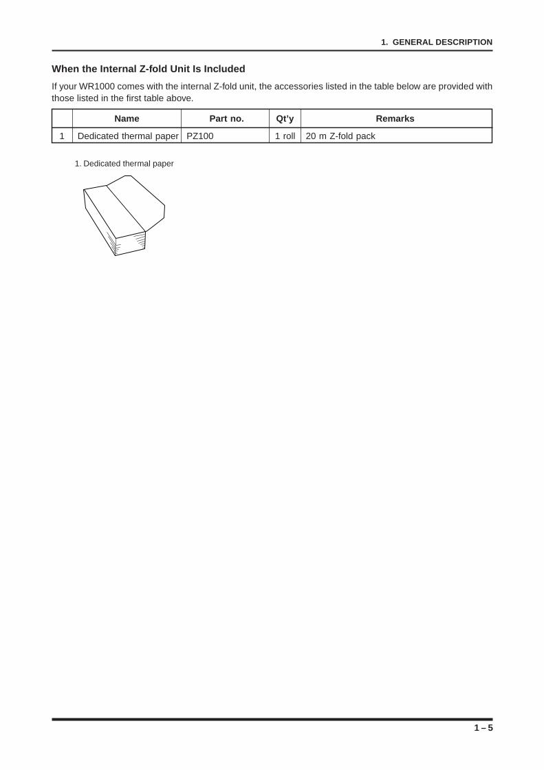
When the Internal Z-fold Unit Is Included
If your WR1000 comes with the internal Z-fold unit, the accessories listed in the table below are provided withthose listed in the first table above.
Name Part no. Qt’y Remarks
1 Dedicated thermal paper PZ100 1 roll 20 m Z-fold pack
1. Dedicated thermal paper

1 – 6
1. GENERAL DESCRIPTION
2 – 1
2. DESCRIPTION OF THE MAIN UNIT’S PARTS
DESCRIPTION OF THE MAIN UNIT’SPARTS
This chapter describes the names and functions of theWR1000’s parts.
2.1 The Front Panel2.1.1 The Display Monitor2.1.2 The Amp Control Panel2.1.3 The Numeric Keypad and CHART SPEED Section2.1.4 The Main Control Panel2.1.5 The Conditions Panel2.2 The Top Panel2.3 The Left Panel2.4 The Right Panel2.5 The Amp Units2.5.1 The V Type Amp2.5.2 The M Type Amp2.5.3 The Logic Amp
CHAPTER 2CHAPTER 2
2 – 2
2. DESCRIPTION OF THE MAIN UNIT’S PARTS
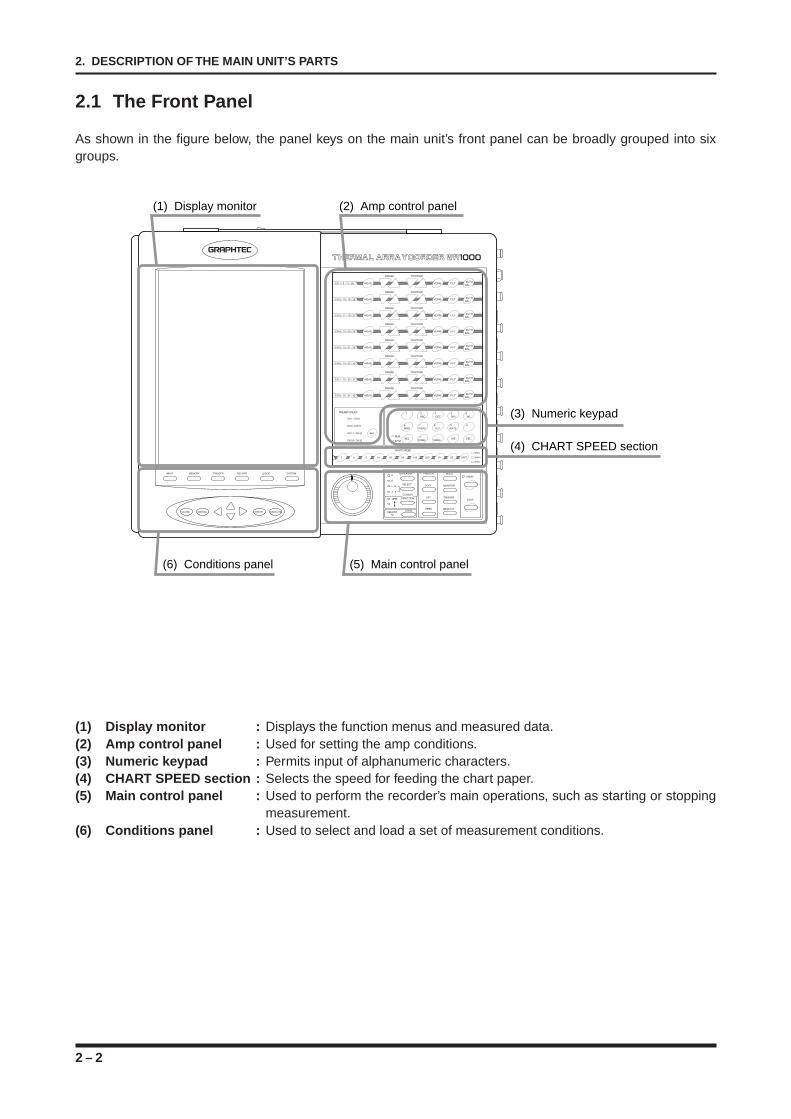
2.1 The Front Panel
As shown in the figure below, the panel keys on the main unit’s front panel can be broadly grouped into sixgroups.
(1) Display monitor (2) Amp control panel
(3) Numeric keypad
(4) CHART SPEED section
(5) Main control panel (6) Conditions panel
(1) Display monitor : Displays the function menus and measured data.(2) Amp control panel : Used for setting the amp conditions.(3) Numeric keypad : Permits input of alphanumeric characters.(4) CHART SPEED section : Selects the speed for feeding the chart paper.(5) Main control panel : Used to perform the recorder’s main operations, such as starting or stopping
measurement.(6) Conditions panel : Used to select and load a set of measurement conditions.
2 – 3
2. DESCRIPTION OF THE MAIN UNIT’S PARTS
2.1.1 The Display Monitor
This subsection describes the monitor display on the main unit’s front panel.
200mm/sRECORDER
CH.1 5V+ 4.893
V
CH.2 5V+ 4.428
V
CH.3 5V+ 4.021
V
CH.4 5V+ 3.625
V
CH.5 5V+ 3.208
V
CH.6 5V+ 2.647
V
CH.7 5V+ 4.299
V
CH.85 V+ 3.850
V
07/MAY/9915:32:30
1
2
3
4
5
6
7
8
(1) Measurement mode display area
(2) Chart speed display area
(3) Date/time display area
(4) Simplified message display area
(5) Display monitor
(6) Position display area
(7) Waveform/settings window display area
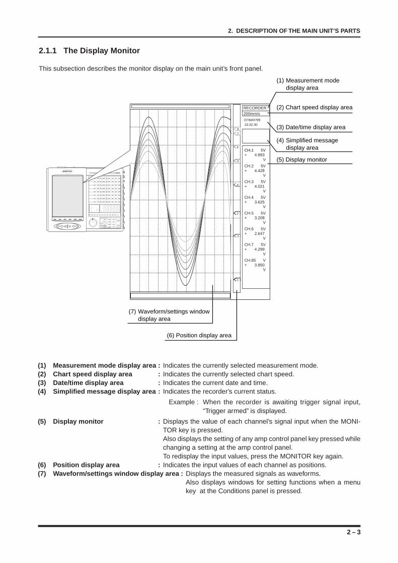
(1) Measurement mode display area : Indicates the currently selected measurement mode.(2) Chart speed display area : Indicates the currently selected chart speed.(3) Date/time display area : Indicates the current date and time.(4) Simplified message display area : Indicates the recorder’s current status.
Example : When the recorder is awaiting trigger signal input,“Trigger armed” is displayed.
(5) Display monitor : Displays the value of each channel’s signal input when the MONI-TOR key is pressed.Also displays the setting of any amp control panel key pressed whilechanging a setting at the amp control panel.To redisplay the input values, press the MONITOR key again.
(6) Position display area : Indicates the input values of each channel as positions.(7) Waveform/settings window display area : Displays the measured signals as waveforms.
Also displays windows for setting functions when a menukey at the Conditions panel is pressed.
2 – 4
2. DESCRIPTION OF THE MAIN UNIT’S PARTS
2.1.2 The Amp Control Panel
This subsection describes the functions of the front panel’s amp control panel.
CH 8 / 16 / 24 / 32 MEAS. VERNI. FILT. AUTO
BAL.
POSITIONRANGE
PREAMP GROUP
CH 1 - CH 8
CH 9 - CH 16
CH 17 - CH 24
CH 25 - CH 32
SEL.
CH 7 / 15 / 23 / 31 MEAS. VERNI. FILT. AUTO
BAL.
POSITIONRANGE
(1) Channel no.
(2) MEAS. key
(3) RANGE keys
(4) POSITION keys
(5) FILT. key
(6) AUTO BAL. Key
(8) SEL. key. (7) VERNI. key
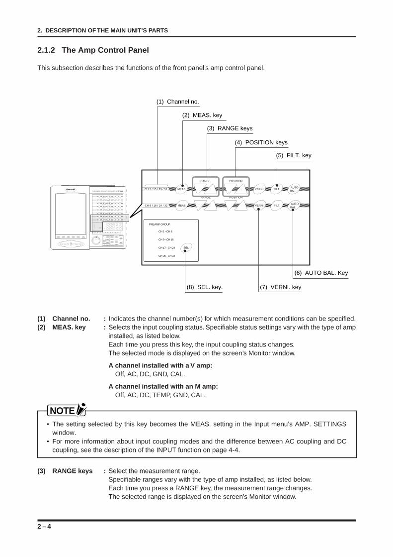
(1) Channel no. : Indicates the channel number(s) for which measurement conditions can be specified.(2) MEAS. key : Selects the input coupling status. Specifiable status settings vary with the type of amp
installed, as listed below.Each time you press this key, the input coupling status changes.The selected mode is displayed on the screen’s Monitor window.
A channel installed with a V amp:Off, AC, DC, GND, CAL.
A channel installed with an M amp:Off, AC, DC, TEMP, GND, CAL.
NOTE• The setting selected by this key becomes the MEAS. setting in the Input menu’s AMP. SETTINGS
window.• For more information about input coupling modes and the difference between AC coupling and DC
coupling, see the description of the INPUT function on page 4-4.
(3) RANGE keys : Select the measurement range.Specifiable ranges vary with the type of amp installed, as listed below.Each time you press a RANGE key, the measurement range changes.The selected range is displayed on the screen’s Monitor window.
2 – 5
2. DESCRIPTION OF THE MAIN UNIT’S PARTS
A channel installed with a V amp:50mV, 100mV, 200mV, 500mV, 1V, 2V, 5V, 10V, 20V, 50V, 100V, 200V, 500V
A channel installed with an M amp:Voltage : 20mV, 50mV, 100mV, 200mV, 500mV, 1V, 2V, 5V, 10V, 20V, 50V, 100V,
200V, 500VTemperature : TC-K, TC-J, TC-T, TC-R, TC-E, TC-B
NOTE • The setting selected by the RANGE keys becomes the RANGE setting in the Input menu’s AMP.
SETTINGS window.• For more information about the automatic selection of the voltage range, see the description of the
RANGE function on page 4-5.
(4) POSITION keys : Specify the zero-point position. Each time you press a POSITION key, the zero-pointposition changes.When you hold down a POSITION key, the POSITION value changes continuouslyuntil the key is released.The selected position is displayed on the screen’s Monitor window.
NOTEThe setting selected by this key becomes the LOWER-SPAN-UPPER settings in the Input menu’s AMP.SETTINGS window.
(5) FILT. key : Selects the filter mode. Each time you press the FILT. key, the filter mode changes.The selected FILTER mode is displayed on the screen’s Monitor window.
[FILTER setting]LINE : 1.5HzLow pass : 5, 10, 30, 50, 500Hz, 5kHz
NOTE• The setting selected by this key becomes the FILTER setting in the Input menu’s AMP. SETTINGS
window.• For more information about the LINE filter and lowpass filter, see the description of the FILTER function
on page 4-5.
(6) AUTO BAL. key : Cannot be used with the V or M type amp.
(7) VERNI. key : Selects the ON/OFF status of the Vernier function.Each time you press the VERNI. key, the VERNIER mode switches between ON andOFF.The selected status is displayed on the screen’s Monitor window.The minimum and maximum values that can be set are the same as the SPAN values.
NOTEFor more information about SPAN values, see Section 4.2, “The Input Menu.”
(8) SEL. key : Selects the pre-amp group for which you wish to perform settings.Each time you press the SEL. key, the pre-amp group changes. A lamp on the left ofthe SEL. key lights to indicates the currently selected pre-amp group.
2 – 6
2. DESCRIPTION OF THE MAIN UNIT’S PARTS
2.1.3 The Numeric Keypad and CHART SPEED Section
This subsection describes the numeric keypad and chart speed section on the main unit’s front panel.
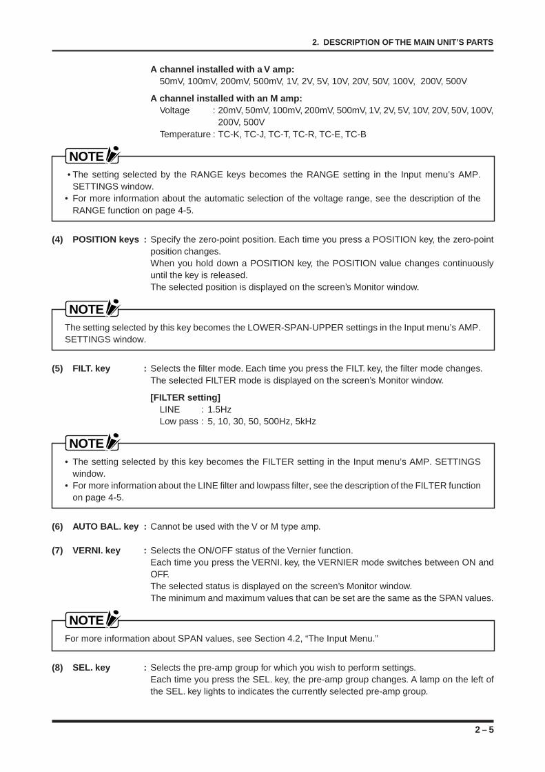
(1) SEL. key : Selects the input mode for character input.Each time the SEL. key is pressed, the input mode switches between numeric(NUM) and alphabetic (ALPHA) input. A lamp on the left of the SEL. key lights toindicate the currently selected input mode.
(2) Alphanumeric keys : Depending on the key pressed, these keys input the corresponding numeral,character, symbol, or space character or perform an editing operation (insertionor deletion).
(3) CHART SPEED value keys : Press one of these keys to set the chart speed to the value indicated onthe key.
NOTEThe chart speed selected using a CHART SPEED value and UNIT keybecomes the CHART SPEED setting in the RECORD SETTINGS menu’sRecord window.
(4) Variable CHART SPEED keys : Press V1 or V2 to change the chart speed to the chart speed of the V1 orV2 setting which you registered in advance at the RECORD SETTINGSmenu’s Record window.
NOTEThe chart speed selected using a CHART SPEED value and UNIT keybecomes the CHART SPEED setting in the RECORD SETTINGS menu’sRecord window.
(5) UNIT key : Selects the unit for the chart speed value selected using a CHART SPEED valuekey. Each time you press this key, the unit changes in the sequence of: mm/s,mm/min, and mm/h. A lamp on the left of this key lights to indicated the currentlyselected unit.
NOTEThe chart speed selected using a CHART SPEED value and UNIT keybecomes the CHART SPEED setting in the RECORD SETTINGS menu’sRecord window.
2 – 7
2. DESCRIPTION OF THE MAIN UNIT’S PARTS
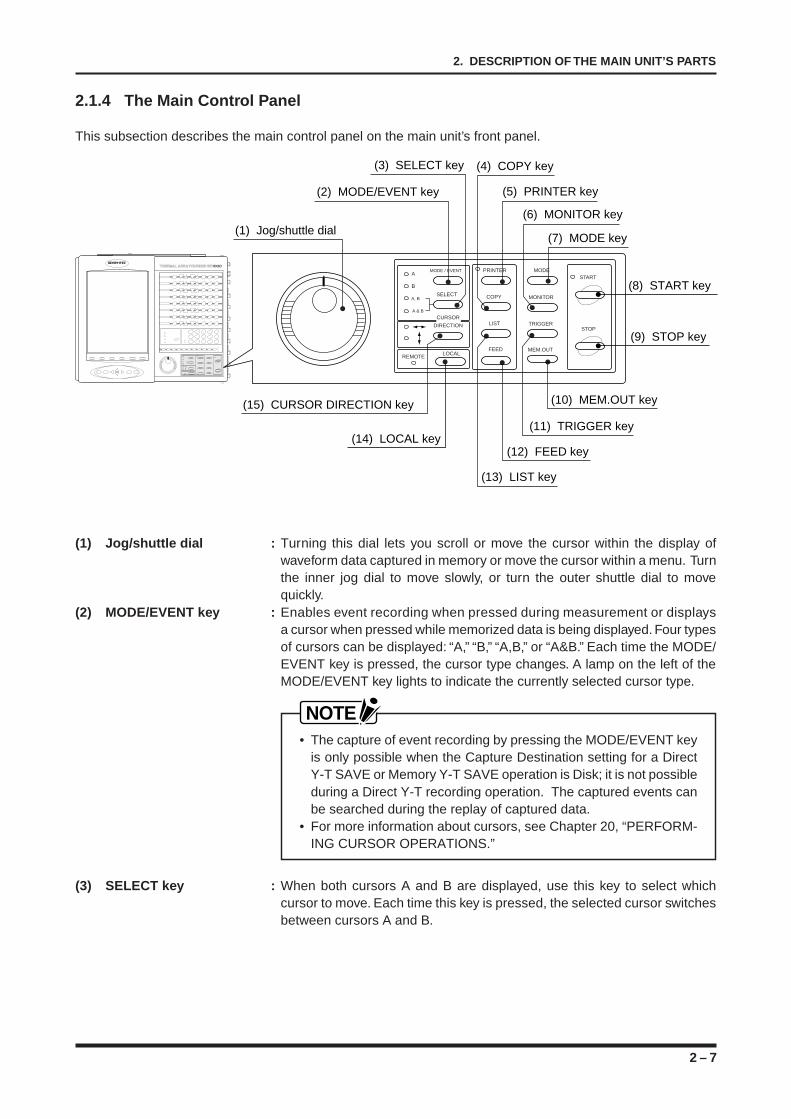
2.1.4 The Main Control Panel
This subsection describes the main control panel on the main unit’s front panel.
(2) MODE/EVENT key
(3) SELECT key
(15) CURSOR DIRECTION key
(5) PRINTER key
(4) COPY key
(13) LIST key
(12) FEED key
(7) MODE key
(6) MONITOR key
(11) TRIGGER key
(10) MEM.OUT key
(8) START key
(9) STOP key
(1) Jog/shuttle dial
MODE / EVENT
SELECT
A
B
A, B
A & B
PRINTER
COPY
LIST
FEED
MODE
MONITOR
TRIGGER
MEM.OUT
START
STOP
LOCALREMOTE
CURSOR
DIRECTION
(14) LOCAL key
(1) Jog/shuttle dial : Turning this dial lets you scroll or move the cursor within the display ofwaveform data captured in memory or move the cursor within a menu. Turnthe inner jog dial to move slowly, or turn the outer shuttle dial to movequickly.
(2) MODE/EVENT key : Enables event recording when pressed during measurement or displaysa cursor when pressed while memorized data is being displayed. Four typesof cursors can be displayed: “A,” “B,” “A,B,” or “A&B.” Each time the MODE/EVENT key is pressed, the cursor type changes. A lamp on the left of theMODE/EVENT key lights to indicate the currently selected cursor type.
NOTE• The capture of event recording by pressing the MODE/EVENT key
is only possible when the Capture Destination setting for a DirectY-T SAVE or Memory Y-T SAVE operation is Disk; it is not possibleduring a Direct Y-T recording operation. The captured events canbe searched during the replay of captured data.
• For more information about cursors, see Chapter 20, “PERFORM-ING CURSOR OPERATIONS.”
(3) SELECT key : When both cursors A and B are displayed, use this key to select whichcursor to move. Each time this key is pressed, the selected cursor switchesbetween cursors A and B.
2 – 8
2. DESCRIPTION OF THE MAIN UNIT’S PARTS
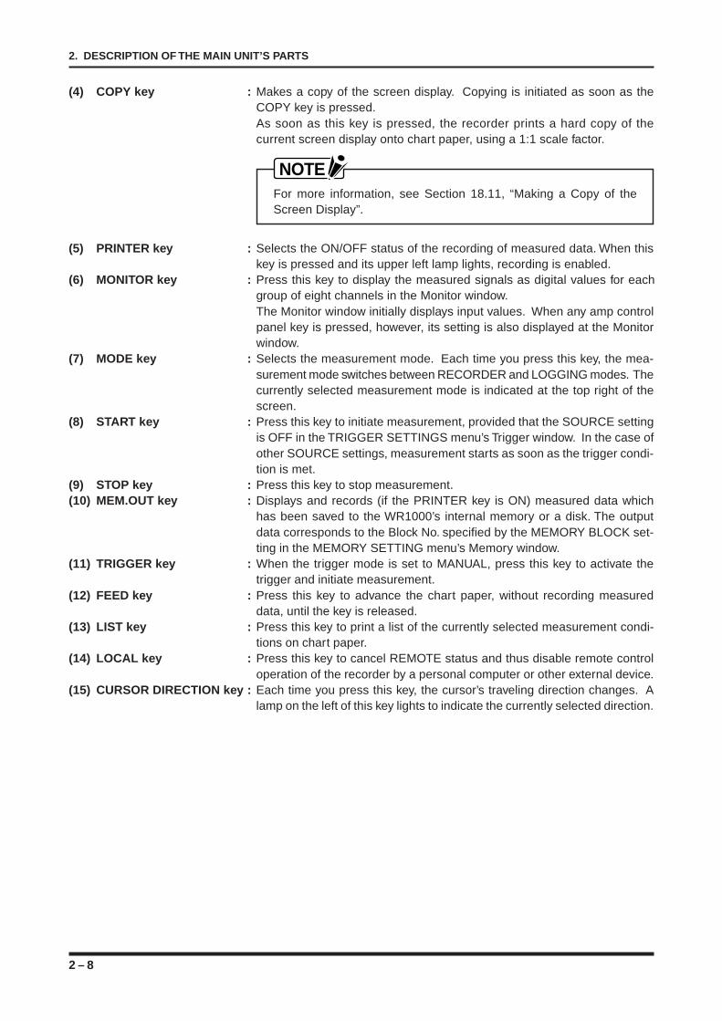
(4) COPY key : Makes a copy of the screen display. Copying is initiated as soon as theCOPY key is pressed.As soon as this key is pressed, the recorder prints a hard copy of thecurrent screen display onto chart paper, using a 1:1 scale factor.
NOTEFor more information, see Section 18.11, “Making a Copy of theScreen Display”.
(5) PRINTER key : Selects the ON/OFF status of the recording of measured data. When thiskey is pressed and its upper left lamp lights, recording is enabled.
(6) MONITOR key : Press this key to display the measured signals as digital values for eachgroup of eight channels in the Monitor window.The Monitor window initially displays input values. When any amp controlpanel key is pressed, however, its setting is also displayed at the Monitorwindow.
(7) MODE key : Selects the measurement mode. Each time you press this key, the mea-surement mode switches between RECORDER and LOGGING modes. Thecurrently selected measurement mode is indicated at the top right of thescreen.
(8) START key : Press this key to initiate measurement, provided that the SOURCE settingis OFF in the TRIGGER SETTINGS menu’s Trigger window. In the case ofother SOURCE settings, measurement starts as soon as the trigger condi-tion is met.
(9) STOP key : Press this key to stop measurement.(10) MEM.OUT key : Displays and records (if the PRINTER key is ON) measured data which
has been saved to the WR1000’s internal memory or a disk. The outputdata corresponds to the Block No. specified by the MEMORY BLOCK set-ting in the MEMORY SETTING menu’s Memory window.
(11) TRIGGER key : When the trigger mode is set to MANUAL, press this key to activate thetrigger and initiate measurement.
(12) FEED key : Press this key to advance the chart paper, without recording measureddata, until the key is released.
(13) LIST key : Press this key to print a list of the currently selected measurement condi-tions on chart paper.
(14) LOCAL key : Press this key to cancel REMOTE status and thus disable remote controloperation of the recorder by a personal computer or other external device.
(15) CURSOR DIRECTION key : Each time you press this key, the cursor’s traveling direction changes. Alamp on the left of this key lights to indicate the currently selected direction.
2 – 9
2. DESCRIPTION OF THE MAIN UNIT’S PARTS
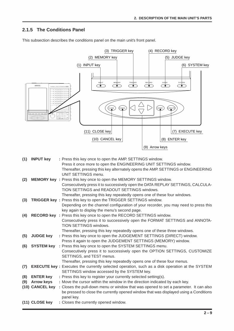
2.1.5 The Conditions Panel
This subsection describes the conditions panel on the main unit’s front panel.
(10) CANCEL key (8) ENTER key
(9) Arrow keys
INPUT MEMORY TRIGGER RECORD JUDGE SYSTEM
CLOSE CANCEL ENTER EXECUTE
(1) INPUT key (6) SYSTEM key
(2) MEMORY key (5) JUDGE key
(3) TRIGGER key (4) RECORD key
(11) CLOSE key (7) EXECUTE key
(1) INPUT key : Press this key once to open the AMP. SETTINGS window.Press it once more to open the ENGINEERING UNIT SETTINGS window.Thereafter, pressing this key alternately opens the AMP. SETTINGS or ENGINEERINGUNIT SETTINGS menu.
(2) MEMORY key : Press this key once to open the MEMORY SETTINGS window.Consecutively press it to successively open the DATA REPLAY SETTINGS, CALCULA-TION SETTINGS and READOUT SETTINGS windows.Thereafter, pressing this key repeatedly opens one of these four windows.
(3) TRIGGER key : Press this key to open the TRIGGER SETTINGS window.Depending on the channel configuration of your recorder, you may need to press thiskey again to display the menu’s second page.
(4) RECORD key : Press this key once to open the RECORD SETTINGS window.Consecutively press it to successively open the FORMAT SETTINGS and ANNOTA-TION SETTINGS windows.Thereafter, pressing this key repeatedly opens one of these three windows.
(5) JUDGE key : Press this key once to open the JUDGEMENT SETTINGS (DIRECT) window.Press it again to open the JUDGEMENT SETTINGS (MEMORY) window.
(6) SYSTEM key : Press this key once to open the SYSTEM SETTINGS menu.Consecutively press it to successively open the OPTION SETTINGS, CUSTOMIZESETTINGS, and TEST menus.Thereafter, pressing this key repeatedly opens one of these four menus.
(7) EXECUTE key : Executes the currently selected operation, such as a disk operation at the SYSTEMSETTINGS window accessed by the SYSTEM key.
(8) ENTER key : Press this key to register your currently selected setting(s).(9) Arrow keys : Move the cursor within the window in the direction indicated by each key.(10) CANCEL key : Closes the pull-down menu or window that was opened to set a parameter. It can also
be pressed to close the currently opened window that was displayed using a Conditionspanel key.
(11) CLOSE key : Closes the currently opened window.
2 – 10
2. DESCRIPTION OF THE MAIN UNIT’S PARTS
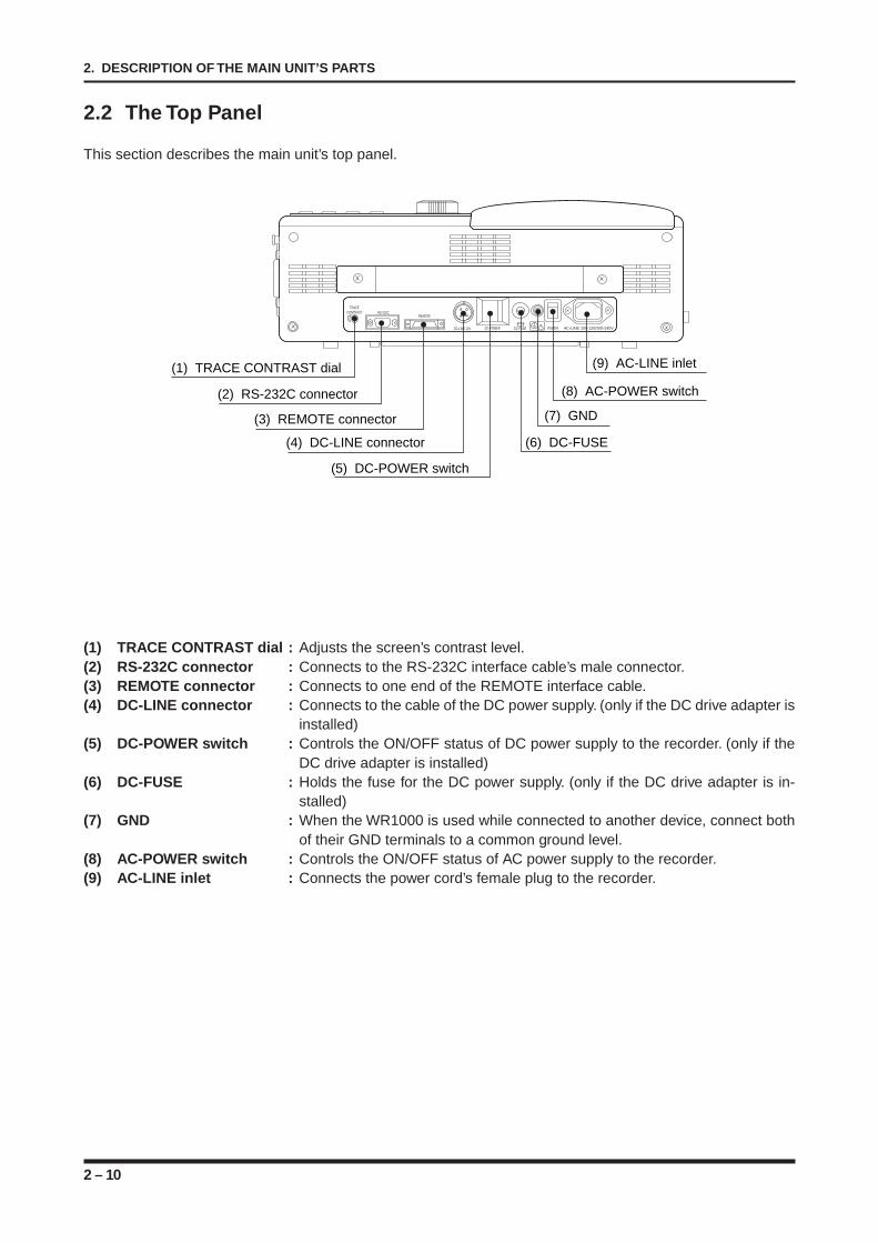
2.2 The Top Panel
This section describes the main unit’s top panel.
AC-LINE 100-120/200-240VPOWERDC-FUSEDC-POWERDC-LINE 12V
REMOTERS-232C
TRACECONTRAST
!
(1) TRACE CONTRAST dial
(2) RS-232C connector
(3) REMOTE connector
(4) DC-LINE connector
(5) DC-POWER switch
(6) DC-FUSE
(7) GND
(8) AC-POWER switch
(9) AC-LINE inlet
(1) TRACE CONTRAST dial : Adjusts the screen’s contrast level.(2) RS-232C connector : Connects to the RS-232C interface cable’s male connector.(3) REMOTE connector : Connects to one end of the REMOTE interface cable.(4) DC-LINE connector : Connects to the cable of the DC power supply. (only if the DC drive adapter is
installed)(5) DC-POWER switch : Controls the ON/OFF status of DC power supply to the recorder. (only if the
DC drive adapter is installed)(6) DC-FUSE : Holds the fuse for the DC power supply. (only if the DC drive adapter is in-
stalled)(7) GND : When the WR1000 is used while connected to another device, connect both
of their GND terminals to a common ground level.(8) AC-POWER switch : Controls the ON/OFF status of AC power supply to the recorder.(9) AC-LINE inlet : Connects the power cord’s female plug to the recorder.
2 – 11
2. DESCRIPTION OF THE MAIN UNIT’S PARTS
2.3 The Left Panel
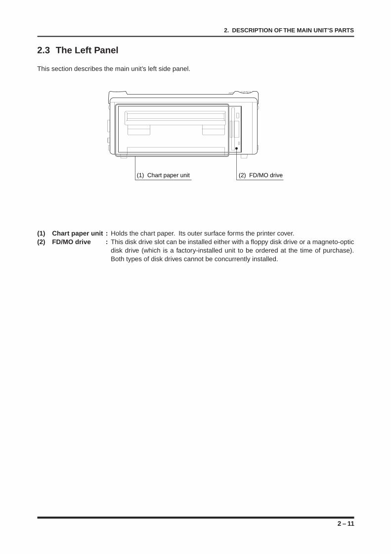
This section describes the main unit’s left side panel.
(1) Chart paper unit (2) FD/MO drive
(1) Chart paper unit : Holds the chart paper. Its outer surface forms the printer cover.(2) FD/MO drive : This disk drive slot can be installed either with a floppy disk drive or a magneto-optic
disk drive (which is a factory-installed unit to be ordered at the time of purchase).Both types of disk drives cannot be concurrently installed.
2 – 12
2. DESCRIPTION OF THE MAIN UNIT’S PARTS
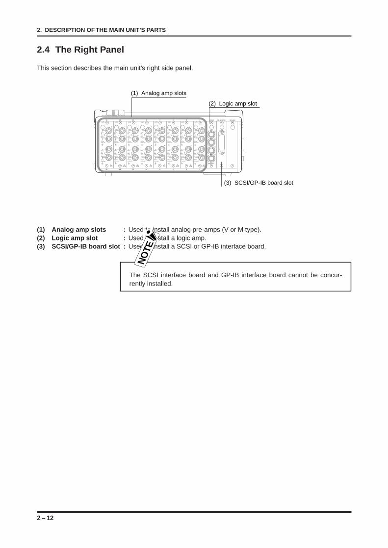
2.4 The Right Panel
This section describes the main unit’s right side panel.
CAT2
+
–
500Vp-pmax.Rangeup to 2V30Vp-p max.
250VCrms(710Vp-p max.)
+
–
500Vp-pmax.Rangeup to 2V30Vp-p max.
250VCrms(710Vp-p max.)
!
+
–
+
–
!
+
–
+
–
!
+
–
+
–
!
+
–
+
–
!
+
–
+
–
!
+
–
+
–
!
+
–
+
–
!
CAT2
500Vp-pmax.Rangeup to 2V30Vp-p max.
250VCrms(710Vp-p max.)
CAT2
500Vp-pmax.Rangeup to 2V30Vp-p max.
250VCrms(710Vp-p max.)
CAT2
500Vp-pmax.Rangeup to 2V30Vp-p max.
250VCrms(710Vp-p max.)
CAT2
500Vp-pmax.Rangeup to 2V30Vp-p max.
250VCrms(710Vp-p max.)
CAT2
500Vp-pmax.Rangeup to 2V30Vp-p max.
250VCrms(710Vp-p max.)
CAT2
500Vp-pmax.Rangeup to 2V30Vp-p max.
250VCrms(710Vp-p max.)
CAT2
500Vp-pmax.Rangeup to 2V30Vp-p max.
250VCrms(710Vp-p max.)
500Vp-pmax.Rangeup to 2V30Vp-p max.
250VCrms(710Vp-p max.)
500Vp-pmax.Rangeup to 2V30Vp-p max.
250VCrms(710Vp-p max.)
500Vp-pmax.Rangeup to 2V30Vp-p max.
250VCrms(710Vp-p max.)
500Vp-pmax.Rangeup to 2V30Vp-p max.
250VCrms(710Vp-p max.)
500Vp-pmax.Rangeup to 2V30Vp-p max.
250VCrms(710Vp-p max.)
500Vp-pmax.Rangeup to 2V30Vp-p max.
250VCrms(710Vp-p max.)
500Vp-pmax.Rangeup to 2V30Vp-p max.
250VCrms(710Vp-p max.)
25Vmax.
A
B
C
D
15 13 11 9 7 5 3 1
246810121416
LOGIC GP-IB/SCSI SOUND
(1) Analog amp slots
(2) Logic amp slot
(3) SCSI/GP-IB board slot
(1) Analog amp slots : Used to install analog pre-amps (V or M type).(2) Logic amp slot : Used to install a logic amp.(3) SCSI/GP-IB board slot : Used to install a SCSI or GP-IB interface board.
NO
TE
The SCSI interface board and GP-IB interface board cannot be concur-rently installed.
2 – 13
2. DESCRIPTION OF THE MAIN UNIT’S PARTS
2.5 The Amp Units
This section describes following three types of amps that can be installed on your recorder:
V type amp : for measuring voltageM type amp : for measuring voltage or temperatureLogic amp : for logic measurements.
2.5.1 The V Type Amp
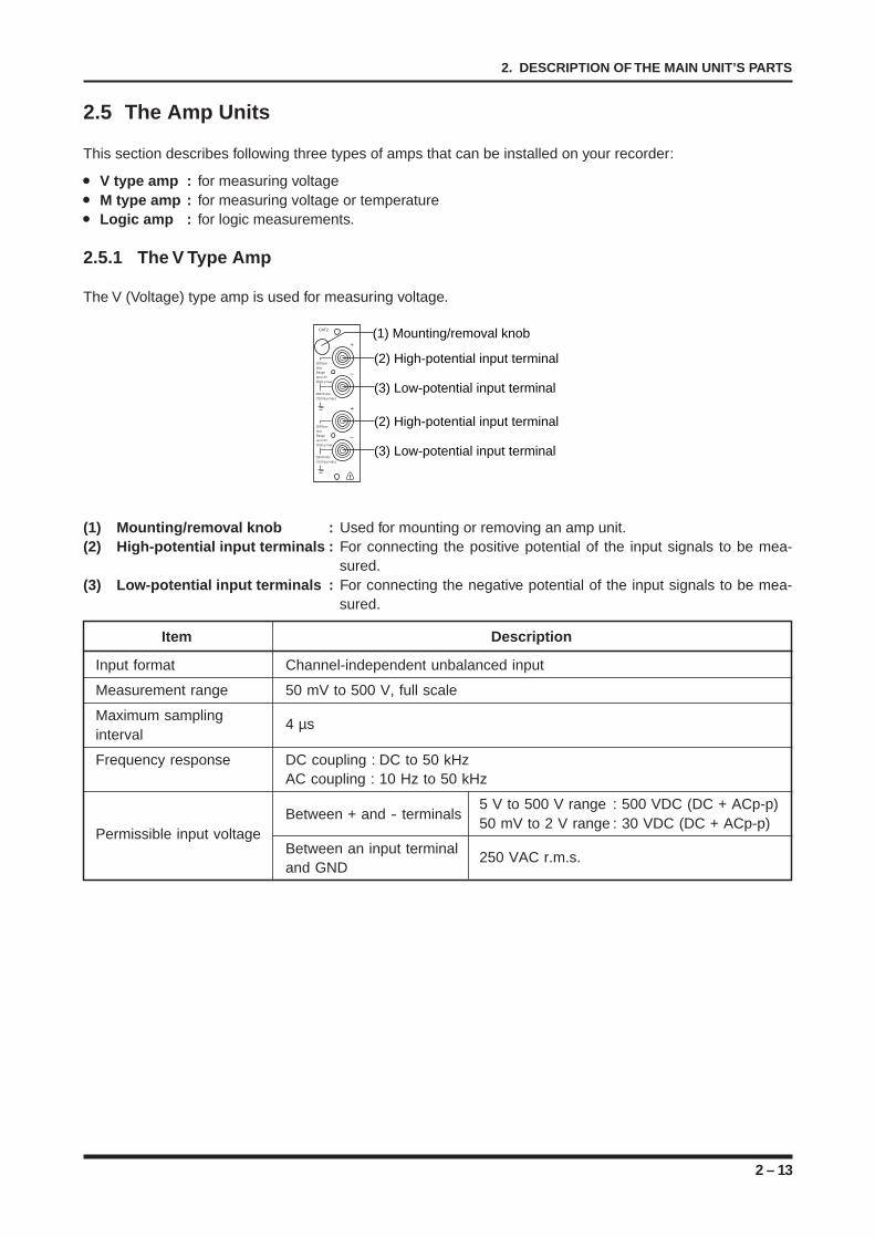
The V (Voltage) type amp is used for measuring voltage.
CAT2
–
500Vp-pmax.Rangeup to 2V30Vp-p max.
250VCrms(710Vp-p max.)
+
+
–
500Vp-pmax.Rangeup to 2V30Vp-p max.
250VCrms(710Vp-p max.)
(2) High-potential input terminal
(3) Low-potential input terminal
(2) High-potential input terminal
(3) Low-potential input terminal
(1) Mounting/removal knob
!
(1) Mounting/removal knob : Used for mounting or removing an amp unit.(2) High-potential input terminals : For connecting the positive potential of the input signals to be mea-
sured.(3) Low-potential input terminals : For connecting the negative potential of the input signals to be mea-
sured.
Item Description
Input format Channel-independent unbalanced input
Measurement range 50 mV to 500 V, full scale
Maximum sampling4 µs
interval
Frequency response DC coupling : DC to 50 kHzAC coupling : 10 Hz to 50 kHz
Between + and - terminals5 V to 500 V range : 500 VDC (DC + ACp-p)50 mV to 2 V range : 30 VDC (DC + ACp-p)
Permissible input voltageBetween an input terminal
250 VAC r.m.s.and GND
2 – 14
2. DESCRIPTION OF THE MAIN UNIT’S PARTS
2.5.2 The M Type Amp
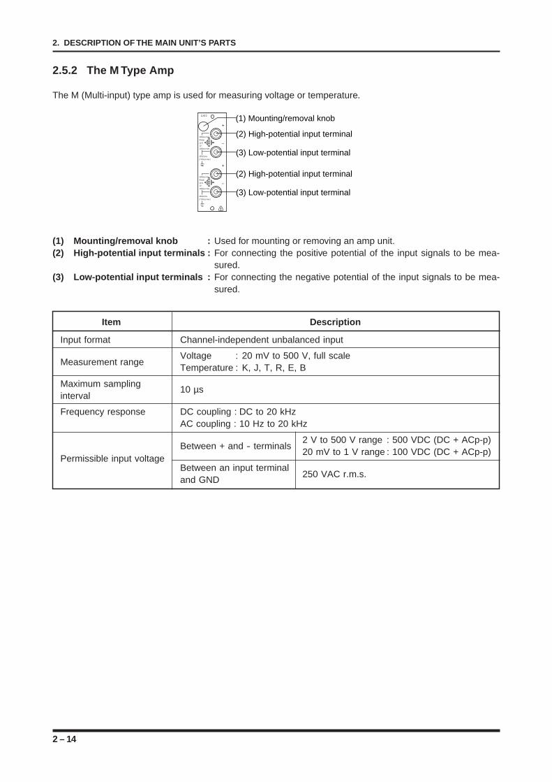
The M (Multi-input) type amp is used for measuring voltage or temperature.
CAT2
–
500Vp-p max.Rangeup to1V :100Vp-p max.
250VCrms(710Vp-p max.)
+
+
–
500Vp-p max.Rangeup to1V :100Vp-p max.
250VCrms(710Vp-p max.)
(2) High-potential input terminal
(3) Low-potential input terminal
(2) High-potential input terminal
(3) Low-potential input terminal
(1) Mounting/removal knob
!
(1) Mounting/removal knob : Used for mounting or removing an amp unit.(2) High-potential input terminals : For connecting the positive potential of the input signals to be mea-
sured.(3) Low-potential input terminals : For connecting the negative potential of the input signals to be mea-
sured.
Item Description
Input format Channel-independent unbalanced input
Measurement rangeVoltage : 20 mV to 500 V, full scaleTemperature : K, J, T, R, E, B
Maximum samplinginterval
10 µs
Frequency response DC coupling : DC to 20 kHzAC coupling : 10 Hz to 20 kHz
Between + and - terminals2 V to 500 V range : 500 VDC (DC + ACp-p)20 mV to 1 V range : 100 VDC (DC + ACp-p)
Permissible input voltageBetween an input terminal
250 VAC r.m.s.and GND
2 – 15
2. DESCRIPTION OF THE MAIN UNIT’S PARTS
2.5.3 The Logic Amp
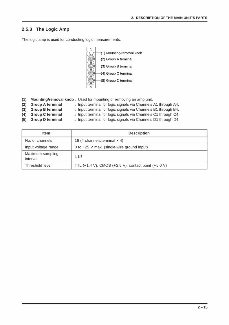
The logic amp is used for conducting logic measurements.
A
B
C
D
(2) Group A terminal
(1) Mounting/removal knob
(3) Group B terminal
(4) Group C terminal
(5) Group D terminal+25Vmax.
(1) Mounting/removal knob : Used for mounting or removing an amp unit.(2) Group A terminal : Input terminal for logic signals via Channels A1 through A4.(3) Group B terminal : Input terminal for logic signals via Channels B1 through B4.(4) Group C terminal : Input terminal for logic signals via Channels C1 through C4.(5) Group D terminal : Input terminal for logic signals via Channels D1 through D4.
Item Description
No. of channels 16 (4 channels/terminal × 4)
Input voltage range 0 to +25 V max. (single-wire ground input)
Maximum samplinginterval
1 µs
Threshold level TTL (+1.4 V), CMOS (+2.5 V), contact point (+5.0 V)

2 – 16
2. DESCRIPTION OF THE MAIN UNIT’S PARTS
3 – 1
3. PREPARATIONS
CHAPTER 3CHAPTER 3PREPARATIONS
This chapter explains how to prepare your recorder foroperation.
3.1 The Working Environment3.1.1 Choosing an Installation Site3.1.2 Positioning the Recorder for Use3.2 Notes on the Liquid Crystal Display Panel3.3 Installing or Removing an Amp3.3.1 Installing an Analog Amp3.3.2 Installing a Logic Amp3.4 Installing or Removing the SCSI or GP-IB Interface
Board3.4.1 Installing the SCSI or GP-IB Interface Board3.5 Connecting the Signal Input Cables3.5.1 Connection to the V (Voltage) Amp3.5.2 Connection to the M (Voltage & Temperature) Amp3.5.3 Connecting the Logic Cable to a Logic Amp3.6 Connecting the Recorder to a Power Supply3.6.1 Connecting to an AC Power Supply3.6.2 Connecting to a DC Power Supply3.7 Loading Chart Paper3.7.1 Loading Roll Paper3.7.2 Mounting the Internal Z-Fold Unit3.7.3 Loading Z-Fold Paper in the Long-Length Z-Fold Unit3.8 Attaching the Writing Table3.9 Changing the Display Language3.10 Momentary Interruption of the AC Power Supply3.11 Protecting the Thermal Printhead3.12 Notes on Temperature Measurement
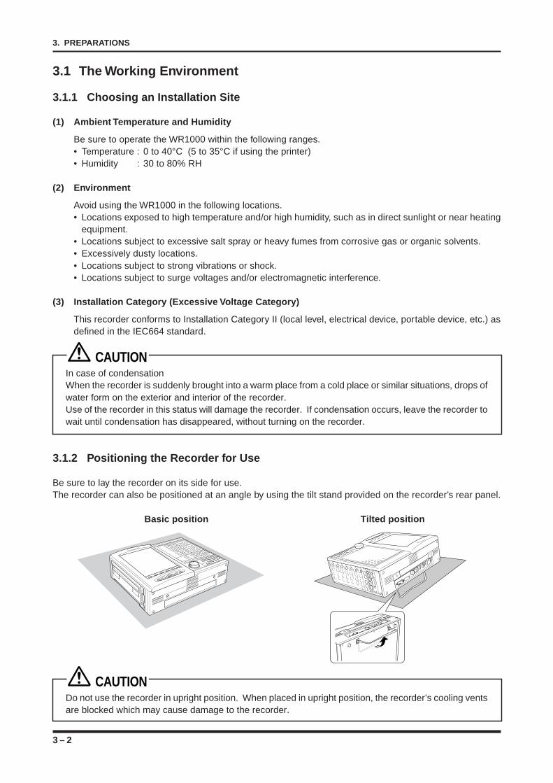
3 – 2
3. PREPARATIONS
3.1 The Working Environment
3.1.1 Choosing an Installation Site
(1) Ambient Temperature and Humidity
Be sure to operate the WR1000 within the following ranges.• Temperature : 0 to 40°C (5 to 35°C if using the printer)• Humidity : 30 to 80% RH
(2) Environment
Avoid using the WR1000 in the following locations.• Locations exposed to high temperature and/or high humidity, such as in direct sunlight or near heating
equipment.• Locations subject to excessive salt spray or heavy fumes from corrosive gas or organic solvents.• Excessively dusty locations.• Locations subject to strong vibrations or shock.• Locations subject to surge voltages and/or electromagnetic interference.
(3) Installation Category (Excessive Voltage Category)
This recorder conforms to Installation Category II (local level, electrical device, portable device, etc.) asdefined in the IEC664 standard.
CAUTIONIn case of condensationWhen the recorder is suddenly brought into a warm place from a cold place or similar situations, drops ofwater form on the exterior and interior of the recorder.Use of the recorder in this status will damage the recorder. If condensation occurs, leave the recorder towait until condensation has disappeared, without turning on the recorder.
3.1.2 Positioning the Recorder for Use
Be sure to lay the recorder on its side for use.The recorder can also be positioned at an angle by using the tilt stand provided on the recorder’s rear panel.
Basic position Tilted position
CAUTIONDo not use the recorder in upright position. When placed in upright position, the recorder’s cooling ventsare blocked which may cause damage to the recorder.
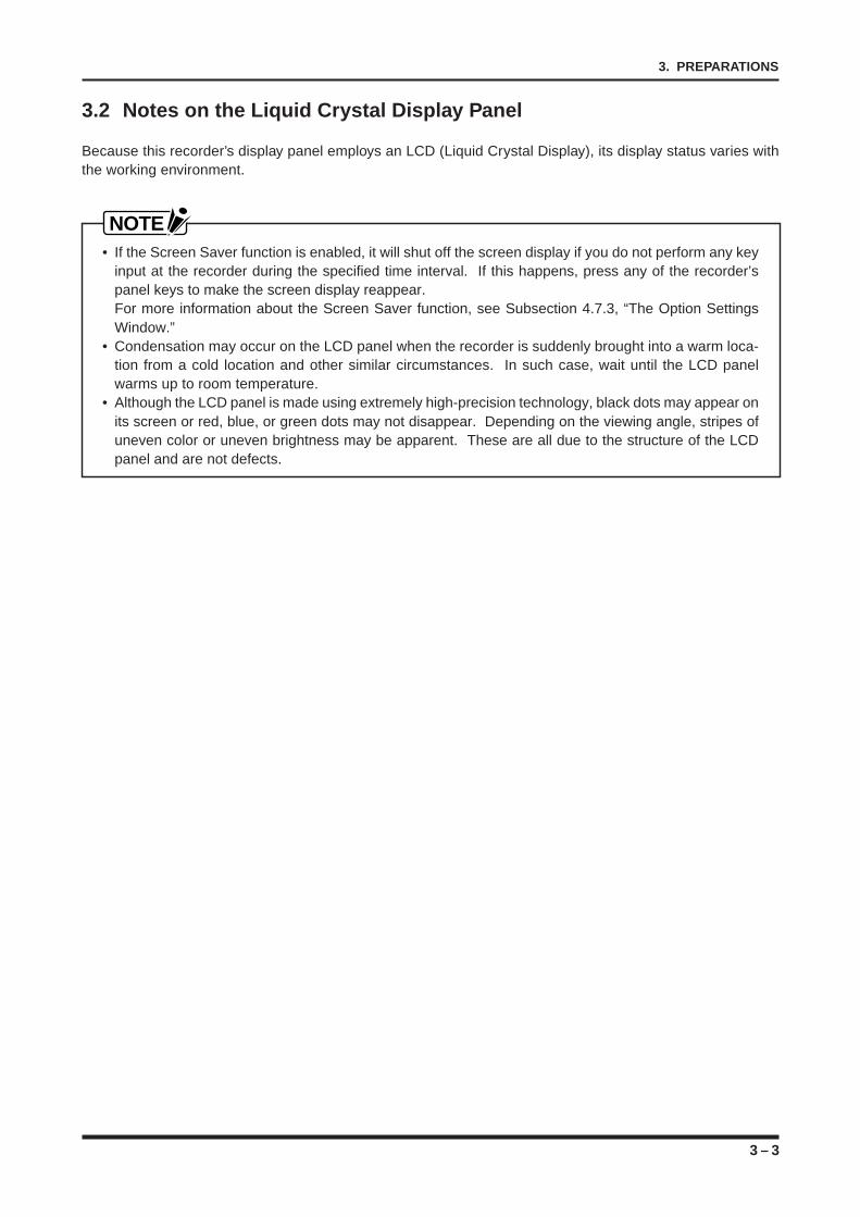
3 – 3
3. PREPARATIONS
3.2 Notes on the Liquid Crystal Display Panel
Because this recorder’s display panel employs an LCD (Liquid Crystal Display), its display status varies withthe working environment.
NOTE• If the Screen Saver function is enabled, it will shut off the screen display if you do not perform any key
input at the recorder during the specified time interval. If this happens, press any of the recorder’spanel keys to make the screen display reappear.For more information about the Screen Saver function, see Subsection 4.7.3, “The Option SettingsWindow.”
• Condensation may occur on the LCD panel when the recorder is suddenly brought into a warm loca-tion from a cold location and other similar circumstances. In such case, wait until the LCD panelwarms up to room temperature.
• Although the LCD panel is made using extremely high-precision technology, black dots may appear onits screen or red, blue, or green dots may not disappear. Depending on the viewing angle, stripes ofuneven color or uneven brightness may be apparent. These are all due to the structure of the LCDpanel and are not defects.
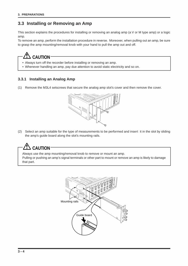
3 – 4
3. PREPARATIONS
3.3 Installing or Removing an Amp
This section explains the procedures for installing or removing an analog amp (a V or M type amp) or a logicamp.To remove an amp, perform the installation procedure in reverse. Moreover, when pulling out an amp, be sureto grasp the amp mounting/removal knob with your hand to pull the amp out and off.
CAUTION• Always turn off the recorder before installing or removing an amp.• Whenever handling an amp, pay due attention to avoid static electricity and so on.
3.3.1 Installing an Analog Amp
(1) Remove the M3L4 setscrews that secure the analog amp slot’s cover and then remove the cover.
(2) Select an amp suitable for the type of measurements to be performed and insert it in the slot by slidingthe amp’s guide board along the slot’s mounting rails.
CAUTIONAlways use the amp mounting/removal knob to remove or mount an amp.Pulling or pushing an amp’s signal terminals or other part to mount or remove an amp is likely to damagethat part.
Mounting rails
Guide board
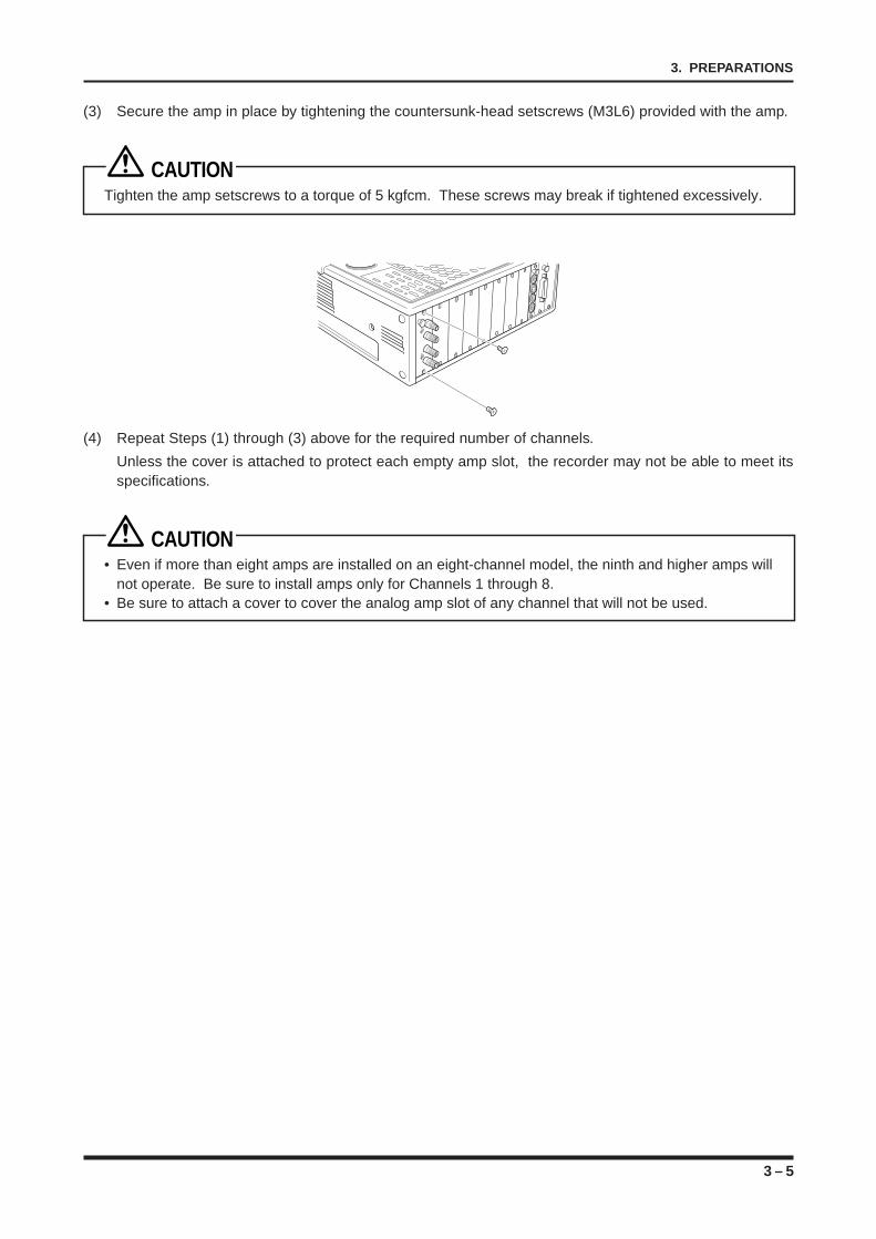
3 – 5
3. PREPARATIONS
(3) Secure the amp in place by tightening the countersunk-head setscrews (M3L6) provided with the amp.
CAUTIONTighten the amp setscrews to a torque of 5 kgfcm. These screws may break if tightened excessively.
(4) Repeat Steps (1) through (3) above for the required number of channels.
Unless the cover is attached to protect each empty amp slot, the recorder may not be able to meet itsspecifications.
CAUTION• Even if more than eight amps are installed on an eight-channel model, the ninth and higher amps will
not operate. Be sure to install amps only for Channels 1 through 8.• Be sure to attach a cover to cover the analog amp slot of any channel that will not be used.
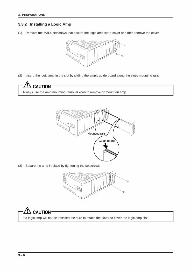
3 – 6
3. PREPARATIONS
3.3.2 Installing a Logic Amp
(1) Remove the M3L4 setscrews that secure the logic amp slot’s cover and then remove the cover.
(2) Insert the logic amp in the slot by sliding the amp’s guide board along the slot’s mounting rails.
CAUTIONAlways use the amp mounting/removal knob to remove or mount an amp.
Mounting rails
Guide board
(3) Secure the amp in place by tightening the setscrews.
CAUTIONIf a logic amp will not be installed, be sure to attach the cover to cover the logic amp slot.
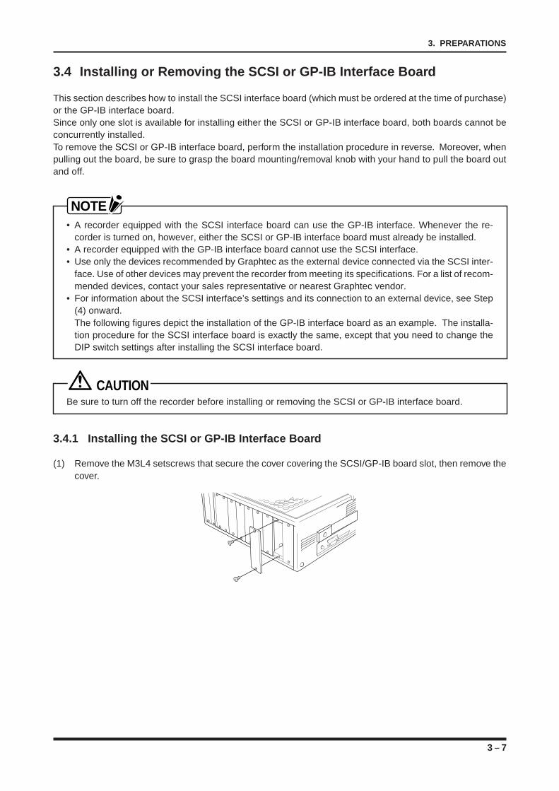
3 – 7
3. PREPARATIONS
3.4 Installing or Removing the SCSI or GP-IB Interface Board
This section describes how to install the SCSI interface board (which must be ordered at the time of purchase)or the GP-IB interface board.Since only one slot is available for installing either the SCSI or GP-IB interface board, both boards cannot beconcurrently installed.To remove the SCSI or GP-IB interface board, perform the installation procedure in reverse. Moreover, whenpulling out the board, be sure to grasp the board mounting/removal knob with your hand to pull the board outand off.
NOTE• A recorder equipped with the SCSI interface board can use the GP-IB interface. Whenever the re-
corder is turned on, however, either the SCSI or GP-IB interface board must already be installed.• A recorder equipped with the GP-IB interface board cannot use the SCSI interface.• Use only the devices recommended by Graphtec as the external device connected via the SCSI inter-
face. Use of other devices may prevent the recorder from meeting its specifications. For a list of recom-mended devices, contact your sales representative or nearest Graphtec vendor.
• For information about the SCSI interface’s settings and its connection to an external device, see Step(4) onward.The following figures depict the installation of the GP-IB interface board as an example. The installa-tion procedure for the SCSI interface board is exactly the same, except that you need to change theDIP switch settings after installing the SCSI interface board.
CAUTIONBe sure to turn off the recorder before installing or removing the SCSI or GP-IB interface board.
3.4.1 Installing the SCSI or GP-IB Interface Board
(1) Remove the M3L4 setscrews that secure the cover covering the SCSI/GP-IB board slot, then remove thecover.
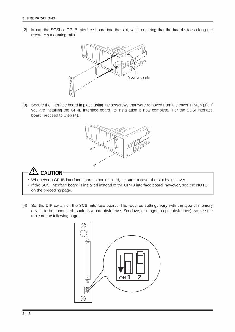
3 – 8
3. PREPARATIONS
(2) Mount the SCSI or GP-IB interface board into the slot, while ensuring that the board slides along therecorder’s mounting rails.
Mounting rails
(3) Secure the interface board in place using the setscrews that were removed from the cover in Step (1). Ifyou are installing the GP-IB interface board, its installation is now complete. For the SCSI interfaceboard, proceed to Step (4).
CAUTION• Whenever a GP-IB interface board is not installed, be sure to cover the slot by its cover.• If the SCSI interface board is installed instead of the GP-IB interface board, however, see the NOTE
on the preceding page.
(4) Set the DIP switch on the SCSI interface board. The required settings vary with the type of memorydevice to be connected (such as a hard disk drive, Zip drive, or magneto-optic disk drive), so see thetable on the following page.
ON1
2
ON 1 2
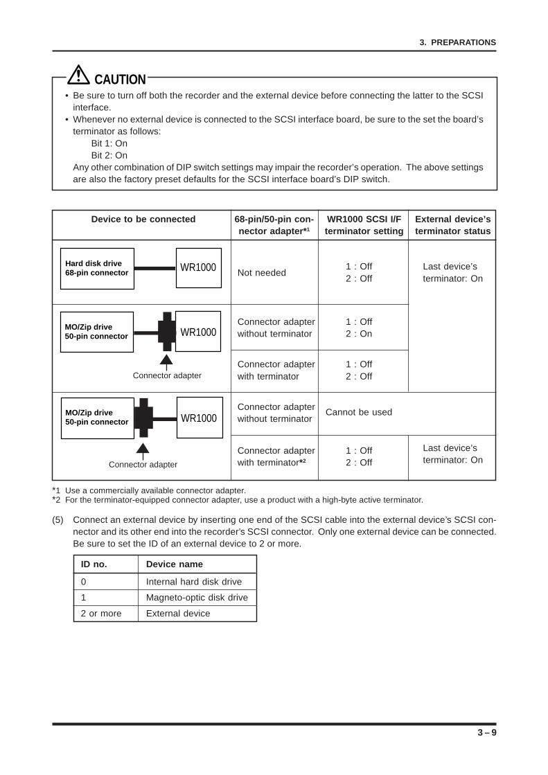
3 – 9
3. PREPARATIONS
CAUTION• Be sure to turn off both the recorder and the external device before connecting the latter to the SCSI
interface.• Whenever no external device is connected to the SCSI interface board, be sure to the set the board’s
terminator as follows:Bit 1: OnBit 2: On
Any other combination of DIP switch settings may impair the recorder’s operation. The above settingsare also the factory preset defaults for the SCSI interface board’s DIP switch.
Device to be connected 68-pin/50-pin con- WR1000 SCSI I/F External device’snector adapter* 1 terminator setting terminator status
Hard disk drive 68-pin connector WR1000 Not needed
1 : Off Last device’s2 : Off terminator: On
Connector adapter 1 : Offwithout terminator 2 : On
MO/Zip drive 50-pin connector WR1000
Connector adapter 1 : Offwith terminator 2 : Off
Connector adapter Cannot be usedwithout terminator
MO/Zip drive 50-pin connector WR1000
Connector adapter 1 : Off Last device’s
with terminator*2 2 : Off terminator: On
*1 Use a commercially available connector adapter.*2 For the terminator-equipped connector adapter, use a product with a high-byte active terminator.
(5) Connect an external device by inserting one end of the SCSI cable into the external device’s SCSI con-nector and its other end into the recorder’s SCSI connector. Only one external device can be connected.Be sure to set the ID of an external device to 2 or more.
ID no. Device name
0 Internal hard disk drive
1 Magneto-optic disk drive
2 or more External device
Connector adapter
Connector adapter
3 – 10
3. PREPARATIONS
CAUTION• Be sure to use a SCSI interface cable that is shielded.• To connect an external device, use an interface cable that is no longer than 0.6 meters long.• When turning on your system, first turn on the external device and then turn on the recorder.• When turning off your system, first turn off the recorder and then turn off the external device.
NOTE• Only one external device can be connected.• Use only the devices recommended by Graphtec as the external device connected via the SCSI
interface. Use of other devices may prevent the recorder from meeting its specifications. For a list ofrecommended devices, contact your sales representative or nearest Graphtec vendor.
• If a hard disk drive is installed as an external device, be sure to reformat its hard disk using the DiskInitialize function in the System Settings window. For more information about the Disk Initialize func-tion, see Section 16.7, “Reformatting a Hard Disk.”
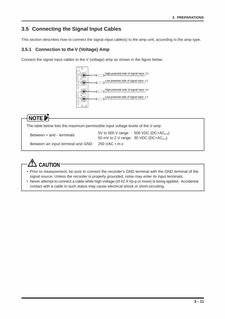
3 – 11
3. PREPARATIONS
3.5 Connecting the Signal Input Cables
This section describes how to connect the signal input cable(s) to the amp unit, according to the amp type.
3.5.1 Connection to the V (Voltage) Amp
Connect the signal input cables to the V (voltage) amp as shown in the figure below.
CAT2
500Vp-pmax.Rangeup to 2V30Vp-p max.
250VCrms(710Vp-p max.)
500Vp-pmax.Rangeup to 2V30Vp-p max.
250VCrms(710Vp-p max.)
!
–
–
+
+
High-potential side of signal input (+)
Low-potential side of signal input (-)
High-potential side of signal input (+)
Low-potential side of signal input (-)
NOTEThe table below lists the maximum permissible input voltage levels of the V amp.
Between + and - terminals 5V to 500 V range : 500 VDC (DC+ACP-P)50 mV to 2 V range : 30 VDC (DC+ACP-P)
Between an input terminal and GND 250 VAC r.m.s
CAUTION• Prior to measurement, be sure to connect the recorder’s GND terminal with the GND terminal of the
signal source. Unless the recorder is properly grounded, noise may enter its input terminals.• Never attempt to connect a cable while high voltage (of 42.4 Vp-p or more) is being applied. Accidental
contact with a cable in such status may cause electrical shock or short-circuiting.
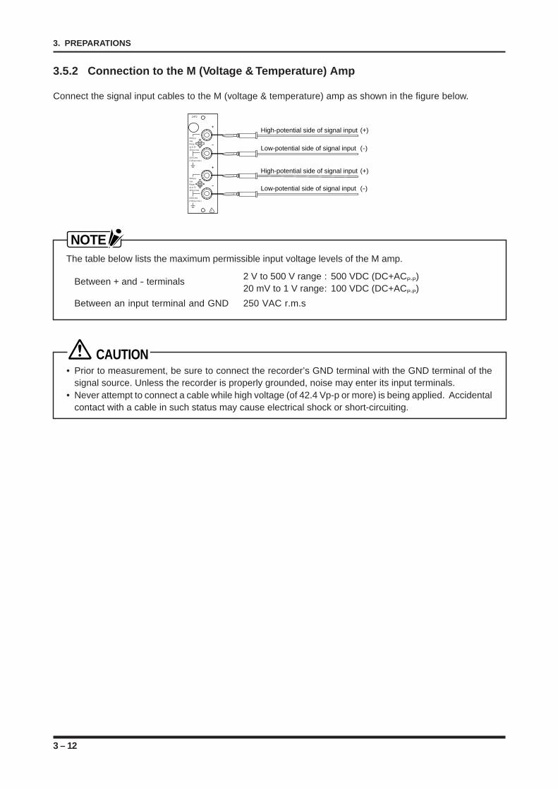
3 – 12
3. PREPARATIONS
3.5.2 Connection to the M (Voltage & Temperature) Amp
Connect the signal input cables to the M (voltage & temperature) amp as shown in the figure below.
CAT2
500Vp-pmax.Rangeup to 2V30Vp-p max.
250VCrms(710Vp-p max.)
500Vp-pmax.Rangeup to 2V30Vp-p max.
250VCrms(710Vp-p max.)
!
–
+
–
+High-potential side of signal input (+)
Low-potential side of signal input (-)
High-potential side of signal input (+)
Low-potential side of signal input (-)
NOTEThe table below lists the maximum permissible input voltage levels of the M amp.
Between + and - terminals 2 V to 500 V range : 500 VDC (DC+ACP-P)20 mV to 1 V range: 100 VDC (DC+ACP-P)
Between an input terminal and GND 250 VAC r.m.s
CAUTION• Prior to measurement, be sure to connect the recorder’s GND terminal with the GND terminal of the
signal source. Unless the recorder is properly grounded, noise may enter its input terminals.• Never attempt to connect a cable while high voltage (of 42.4 Vp-p or more) is being applied. Accidental
contact with a cable in such status may cause electrical shock or short-circuiting.
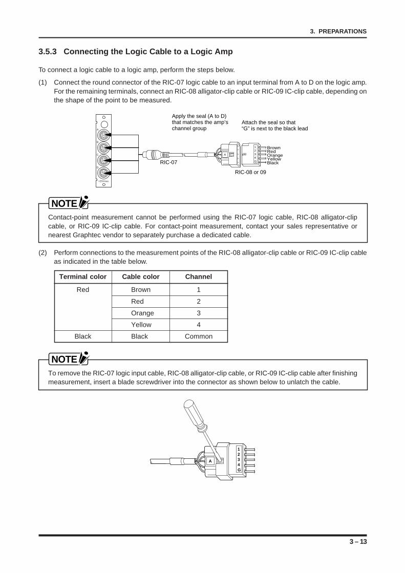
3 – 13
3. PREPARATIONS
3.5.3 Connecting the Logic Cable to a Logic Amp
To connect a logic cable to a logic amp, perform the steps below.
(1) Connect the round connector of the RIC-07 logic cable to an input terminal from A to D on the logic amp.For the remaining terminals, connect an RIC-08 alligator-clip cable or RIC-09 IC-clip cable, depending onthe shape of the point to be measured.
A
B
C
D
+25Vmax.
1234GRIC-07
A
RIC-08 or 09
Attach the seal so that “G” is next to the black lead
BrownRedOrangeYellowBlack
Apply the seal (A to D) that matches the amp’s channel group
NOTEContact-point measurement cannot be performed using the RIC-07 logic cable, RIC-08 alligator-clipcable, or RIC-09 IC-clip cable. For contact-point measurement, contact your sales representative ornearest Graphtec vendor to separately purchase a dedicated cable.
(2) Perform connections to the measurement points of the RIC-08 alligator-clip cable or RIC-09 IC-clip cableas indicated in the table below.
Terminal color Cable color Channel
Red Brown 1
Red 2
Orange 3
Yellow 4
Black Black Common
NOTETo remove the RIC-07 logic input cable, RIC-08 alligator-clip cable, or RIC-09 IC-clip cable after finishingmeasurement, insert a blade screwdriver into the connector as shown below to unlatch the cable.
1234G
A
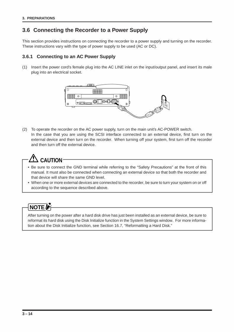
3 – 14
3. PREPARATIONS
3.6 Connecting the Recorder to a Power Supply
This section provides instructions on connecting the recorder to a power supply and turning on the recorder.These instructions vary with the type of power supply to be used (AC or DC).
3.6.1 Connecting to an AC Power Supply
(1) Insert the power cord’s female plug into the AC LINE inlet on the input/output panel, and insert its maleplug into an electrical socket.
(2) To operate the recorder on the AC power supply, turn on the main unit’s AC-POWER switch.In the case that you are using the SCSI interface connected to an external device, first turn on theexternal device and then turn on the recorder. When turning off your system, first turn off the recorderand then turn off the external device.
CAUTION• Be sure to connect the GND terminal while referring to the “Safety Precautions” at the front of this
manual. It must also be connected when connecting an external device so that both the recorder andthat device will share the same GND level.
• When one or more external devices are connected to the recorder, be sure to turn your system on or offaccording to the sequence described above.
NOTEAfter turning on the power after a hard disk drive has just been installed as an external device, be sure toreformat its hard disk using the Disk Initialize function in the System Settings window. For more informa-tion about the Disk Initialize function, see Section 16.7, “Reformatting a Hard Disk.”
3 – 15
3. PREPARATIONS
3.6.2 Connecting to a DC Power Supply
This recorder is certified to display the CE mark when an external DC filter box is connected to the DC adapterunit.If the recorder will be run using the DC adapter unit within the EU region, always connect the recorder and itsDC adapter unit to an external DC filter box for use.If you purchased the WR1000 equipped with the DC adapter unit outside of the EU, please note that it willnot come with an external DC filter box nor be in compliance with the CE standard.
The following explains how to connect the recorder to a DC power supply, depending on whether or not anexternal DC filter box will be used. Connect the DC power supply in accordance with your working environ-ment.
(1) Connecting to a DC Power Supply without Using an External DC Filter Box(2) Using an External DC Filter Box to Connect a DC Power Supply
Moreover, the DC adapter unit is available in two types: the 12 VDC type and 24 VDC type. Be sure to use apower supply that conforms to the specifications of the DC adapter unit that you have connected.When running on a DC power supply, the maximum chart speed becomes 25 mm per second.
[ Connecting to a DC Power Supply without Using an External DC Filter Box ]
(1) Connect the DC power cord to an external DC power supply (+12 VDC or +24 VDC).Connect the “red, orange, yellow, brown, and green” leads to the + terminal of the external DC powersupply, connect the “black, gray, white, navy blue and sky blue” leads to the - terminal of the externalDC power supply, and connect the black and white lead to the GND terminal of the external DC powersupply. There are five leads each for connection to the + and - terminals plus one lead for connection tothe GND terminal, so be sure to connect all 11 leads.
(2) Connect the DC power cord to the WR1000’s DC LINE inlet.Whether the DC power is turned on or off, the WR1000 is turned on as soon as the DC power cord isconnected.In the case that you are using the SCSI interface connected to an external device, first turn on theexternal device(s) and then turn on the recorder. When turning off your system, first turn off the recorderand then turn off the external device(s).
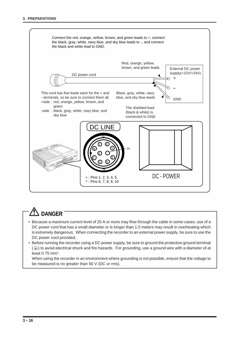
3 – 16
3. PREPARATIONS
Connect the red, orange, vellow, brown, and green leads to +, connectthe black, gray, white, navy blue, and sky blue leads to -, and connectthe black and white lead to GND.
DC LINE
+ : Pins 1, 2, 3, 4, 5- : Pins 6, 7, 8, 9, 10
1
2 3
4
5
67
8
9
10
DC - POWER
Red, orange, yellow,brown, and green leads
DC power cord
External DC powersupply(+12V/+24V)
This cord has five leads each for the + and- terminals, so be sure to connect them all.+side : red, orange, yellow, brown, and
green-side : black, gray, white, navy blue, and
sky blue
Black, gray, white, navy blue, and sky blue leads
The shielded lead(black & white) isconnected to GND
+
-
GND
DANGER• Because a maximum current level of 20 A or more may flow through the cable in some cases, use of a
DC power cord that has a small diameter or is longer than 1.5 meters may result in overheating whichis extremely dangerous. When connecting the recorder to an external power supply, be sure to use theDC power cord provided.
• Before running the recorder using a DC power supply, be sure to ground the protective ground terminal( ) to avoid electrical shock and fire hazards. For grounding, use a ground wire with a diameter of atleast 0.75 mm2.When using the recorder in an environment where grounding is not possible, ensure that the voltage tobe measured is no greater than 50 V (DC or rms).
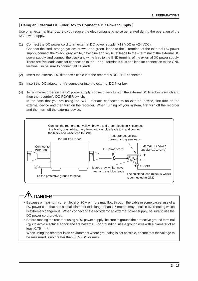
3 – 17
3. PREPARATIONS
[ Using an External DC Filter Box to Connect a DC Power Supply ]
Use of an external filter box lets you reduce the electromagnetic noise generated during the operation of theDC power supply.
(1) Connect the DC power cord to an external DC power supply (+12 VDC or +24 VDC).Connect the “red, orange, yellow, brown, and green” leads to the + terminal of the external DC powersupply, connect the “black, gray, white, navy blue and sky blue” leads to the - terminal of the external DCpower supply, and connect the black and white lead to the GND terminal of the external DC power supply.There are five leads each for connection to the + and - terminals plus one lead for connection to the GNDterminal, so be sure to connect all 11 leads.
(2) Insert the external DC filter box’s cable into the recorder’s DC LINE connector.
(3) Insert the DC adapter unit’s connector into the external DC filter box.
(4) To run the recorder on the DC power supply, consecutively turn on the external DC filter box’s switch andthen the recorder’s DC-POWER switch.In the case that you are using the SCSI interface connected to an external device, first turn on theexternal device and then turn on the recorder. When turning off your system, first turn off the recorderand then turn off the external device.
External DC powersupply(+12V/+24V)
+-GND
Connect the red, orange, vellow, brown, and green" leads to +, connect the black, gray, white, navy blue, and sky blue leads to -, and connectthe black and white lead to GND.
DC FILTER BOXRed, orange, yellow,brown, and green leads
DC power cord
Black, gray, white, navy blue, and sky blue leads
The shielded lead (black & white) is connected to GNDTo the protective ground terminal
Connect to WR1000
DANGER• Because a maximum current level of 20 A or more may flow through the cable in some cases, use of a
DC power cord that has a small diameter or is longer than 1.5 meters may result in overheating whichis extremely dangerous. When connecting the recorder to an external power supply, be sure to use theDC power cord provided.
• Before running the recorder using a DC power supply, be sure to ground the protective ground terminal( ) to avoid electrical shock and fire hazards. For grounding, use a ground wire with a diameter of atleast 0.75 mm2.When using the recorder in an environment where grounding is not possible, ensure that the voltage tobe measured is no greater than 50 V (DC or rms).
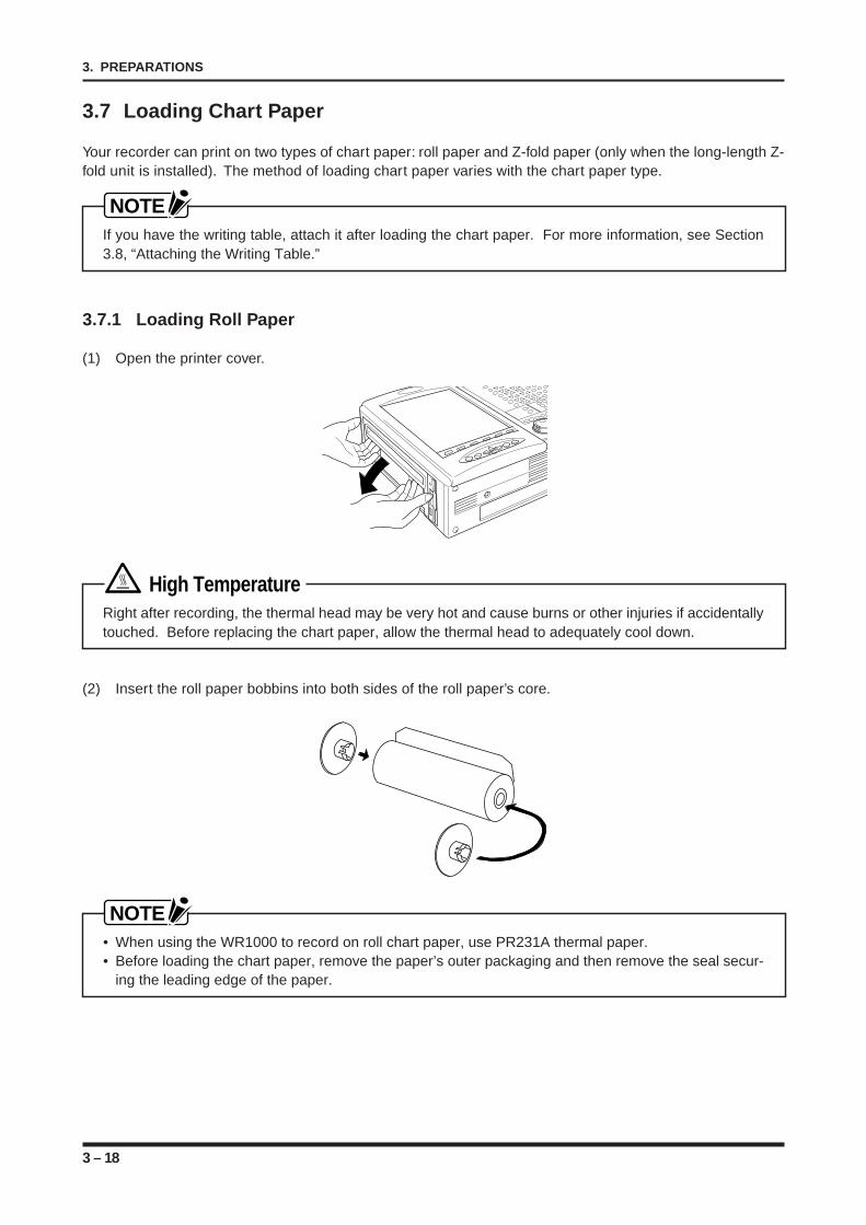
3 – 18
3. PREPARATIONS
3.7 Loading Chart Paper
Your recorder can print on two types of chart paper: roll paper and Z-fold paper (only when the long-length Z-fold unit is installed). The method of loading chart paper varies with the chart paper type.
NOTEIf you have the writing table, attach it after loading the chart paper. For more information, see Section3.8, “Attaching the Writing Table.”
3.7.1 Loading Roll Paper
(1) Open the printer cover.
High TemperatureRight after recording, the thermal head may be very hot and cause burns or other injuries if accidentallytouched. Before replacing the chart paper, allow the thermal head to adequately cool down.
(2) Insert the roll paper bobbins into both sides of the roll paper’s core.
NOTE• When using the WR1000 to record on roll chart paper, use PR231A thermal paper.• Before loading the chart paper, remove the paper’s outer packaging and then remove the seal secur-
ing the leading edge of the paper.
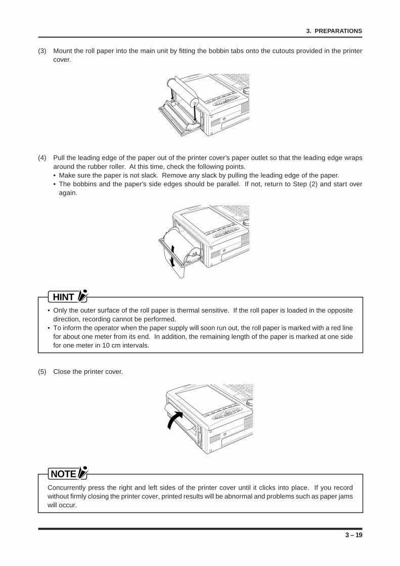
3 – 19
3. PREPARATIONS
(3) Mount the roll paper into the main unit by fitting the bobbin tabs onto the cutouts provided in the printercover.
(4) Pull the leading edge of the paper out of the printer cover’s paper outlet so that the leading edge wrapsaround the rubber roller. At this time, check the following points.• Make sure the paper is not slack. Remove any slack by pulling the leading edge of the paper.• The bobbins and the paper’s side edges should be parallel. If not, return to Step (2) and start over
again.
HINT• Only the outer surface of the roll paper is thermal sensitive. If the roll paper is loaded in the opposite
direction, recording cannot be performed.• To inform the operator when the paper supply will soon run out, the roll paper is marked with a red line
for about one meter from its end. In addition, the remaining length of the paper is marked at one sidefor one meter in 10 cm intervals.
(5) Close the printer cover.
NOTEConcurrently press the right and left sides of the printer cover until it clicks into place. If you recordwithout firmly closing the printer cover, printed results will be abnormal and problems such as paper jamswill occur.
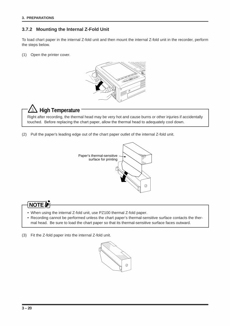
3 – 20
3. PREPARATIONS
3.7.2 Mounting the Internal Z-Fold Unit
To load chart paper in the internal Z-fold unit and then mount the internal Z-fold unit in the recorder, performthe steps below.
(1) Open the printer cover.
High TemperatureRight after recording, the thermal head may be very hot and cause burns or other injuries if accidentallytouched. Before replacing the chart paper, allow the thermal head to adequately cool down.
(2) Pull the paper’s leading edge out of the chart paper outlet of the internal Z-fold unit.
Paper’s thermal-sensitivesurface for printing
NOTE• When using the internal Z-fold unit, use PZ100 thermal Z-fold paper.• Recording cannot be performed unless the chart paper’s thermal-sensitive surface contacts the ther-
mal head. Be sure to load the chart paper so that its thermal-sensitive surface faces outward.
(3) Fit the Z-fold paper into the internal Z-fold unit.
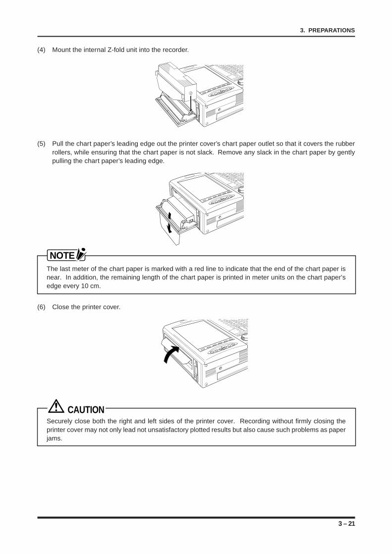
3 – 21
3. PREPARATIONS
(4) Mount the internal Z-fold unit into the recorder.
(5) Pull the chart paper’s leading edge out the printer cover’s chart paper outlet so that it covers the rubberrollers, while ensuring that the chart paper is not slack. Remove any slack in the chart paper by gentlypulling the chart paper’s leading edge.
NOTEThe last meter of the chart paper is marked with a red line to indicate that the end of the chart paper isnear. In addition, the remaining length of the chart paper is printed in meter units on the chart paper’sedge every 10 cm.
(6) Close the printer cover.
CAUTIONSecurely close both the right and left sides of the printer cover. Recording without firmly closing theprinter cover may not only lead not unsatisfactory plotted results but also cause such problems as paperjams.
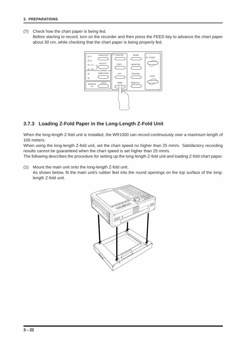
3 – 22
3. PREPARATIONS
(7) Check how the chart paper is being fed.Before starting to record, turn on the recorder and then press the FEED key to advance the chart paperabout 30 cm, while checking that the chart paper is being properly fed.
MODE/EVENT
SELECT
LOCALREMOTE
A
B
A, B
A&B
PRINTER
COPY
LIST
FEED
MODE
MONITOR
TRIGGER
MEM.OUT
START
STOP
CURSOL
DIRECTION
3.7.3 Loading Z-Fold Paper in the Long-Length Z-Fold Unit
When the long-length Z-fold unit is installed, the WR1000 can record continuously over a maximum length of100 meters.When using the long-length Z-fold unit, set the chart speed no higher than 25 mm/s. Satisfactory recordingresults cannot be guaranteed when the chart speed is set higher than 25 mm/s.The following describes the procedure for setting up the long-length Z-fold unit and loading Z-fold chart paper.
(1) Mount the main unit onto the long-length Z-fold unit.As shown below, fit the main unit’s rubber feet into the round openings on the top surface of the long-length Z-fold unit.
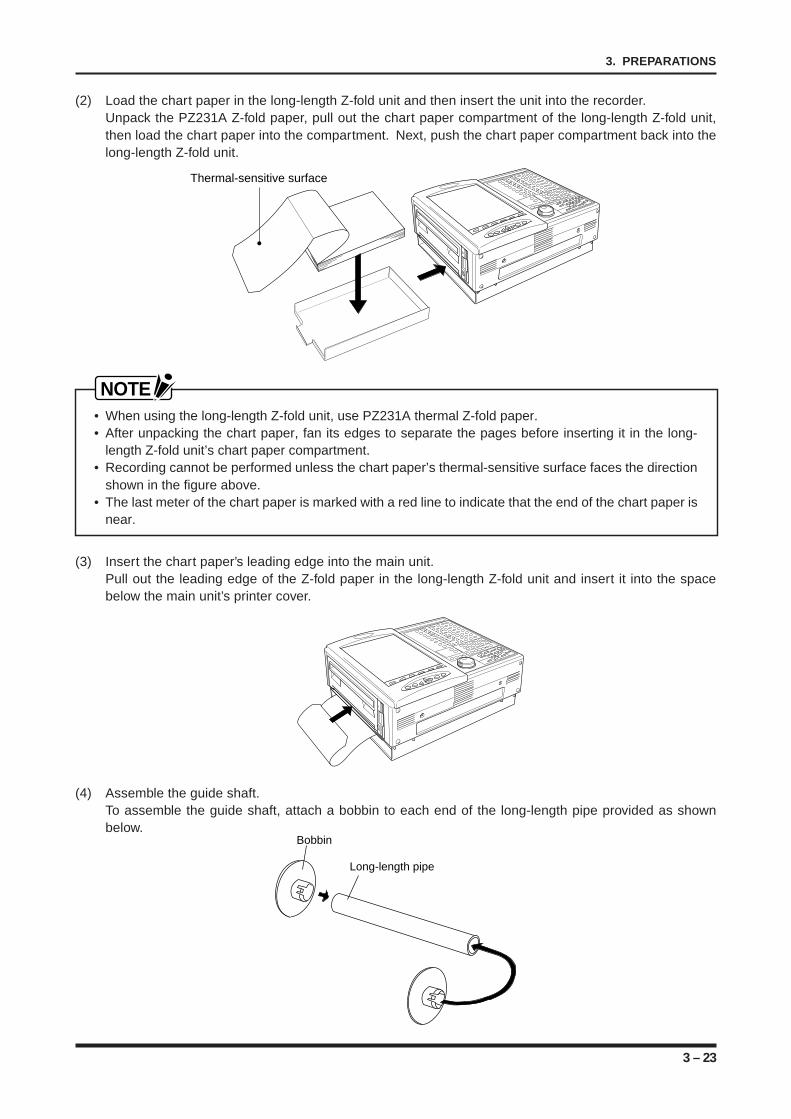
3 – 23
3. PREPARATIONS
(2) Load the chart paper in the long-length Z-fold unit and then insert the unit into the recorder.Unpack the PZ231A Z-fold paper, pull out the chart paper compartment of the long-length Z-fold unit,then load the chart paper into the compartment. Next, push the chart paper compartment back into thelong-length Z-fold unit.
Thermal-sensitive surface
NOTE• When using the long-length Z-fold unit, use PZ231A thermal Z-fold paper.• After unpacking the chart paper, fan its edges to separate the pages before inserting it in the long-
length Z-fold unit’s chart paper compartment.• Recording cannot be performed unless the chart paper’s thermal-sensitive surface faces the direction
shown in the figure above.• The last meter of the chart paper is marked with a red line to indicate that the end of the chart paper is
near.
(3) Insert the chart paper’s leading edge into the main unit.Pull out the leading edge of the Z-fold paper in the long-length Z-fold unit and insert it into the spacebelow the main unit’s printer cover.
(4) Assemble the guide shaft.To assemble the guide shaft, attach a bobbin to each end of the long-length pipe provided as shownbelow.
Bobbin
Long-length pipe
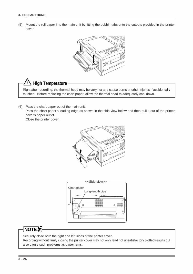
3 – 24
3. PREPARATIONS
(5) Mount the roll paper into the main unit by fitting the bobbin tabs onto the cutouts provided in the printercover.
High TemperatureRight after recording, the thermal head may be very hot and cause burns or other injuries if accidentallytouched. Before replacing the chart paper, allow the thermal head to adequately cool down.
(6) Pass the chart paper out of the main unit.Pass the chart paper’s leading edge as shown in the side view below and then pull it out of the printercover’s paper outlet.Close the printer cover.
Chart paperLong-length pipe
<<Side view>>
NOTESecurely close both the right and left sides of the printer cover.Recording without firmly closing the printer cover may not only lead not unsatisfactory plotted results butalso cause such problems as paper jams.
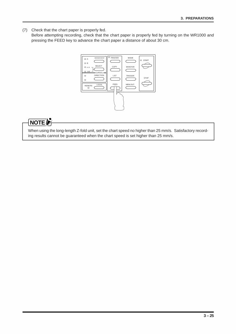
3 – 25
3. PREPARATIONS
(7) Check that the chart paper is properly fed.Before attempting recording, check that the chart paper is properly fed by turning on the WR1000 andpressing the FEED key to advance the chart paper a distance of about 30 cm.
MODE/EVENT
SELECT
LOCALREMOTE
A
B
A, B
A&B
PRINTER
COPY
LIST
FEED
MODE
MONITOR
TRIGGER
MEM.OUT
START
STOP
CURSOL
DIRECTION
NOTEWhen using the long-length Z-fold unit, set the chart speed no higher than 25 mm/s. Satisfactory record-ing results cannot be guaranteed when the chart speed is set higher than 25 mm/s.
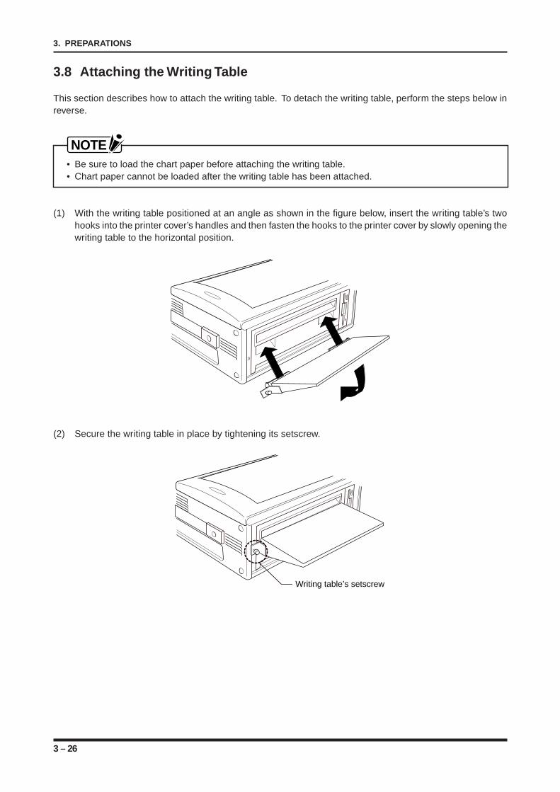
3 – 26
3. PREPARATIONS
3.8 Attaching the Writing Table
This section describes how to attach the writing table. To detach the writing table, perform the steps below inreverse.
NOTE• Be sure to load the chart paper before attaching the writing table.• Chart paper cannot be loaded after the writing table has been attached.
(1) With the writing table positioned at an angle as shown in the figure below, insert the writing table’s twohooks into the printer cover’s handles and then fasten the hooks to the printer cover by slowly opening thewriting table to the horizontal position.
(2) Secure the writing table in place by tightening its setscrew.
Writing table’s setscrew
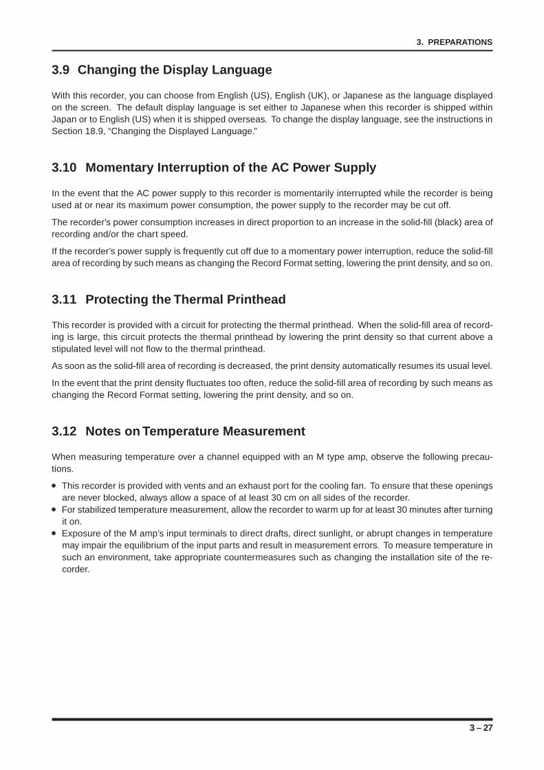
3 – 27
3. PREPARATIONS
3.9 Changing the Display Language
With this recorder, you can choose from English (US), English (UK), or Japanese as the language displayedon the screen. The default display language is set either to Japanese when this recorder is shipped withinJapan or to English (US) when it is shipped overseas. To change the display language, see the instructions inSection 18.9, “Changing the Displayed Language.”
3.10 Momentary Interruption of the AC Power Supply
In the event that the AC power supply to this recorder is momentarily interrupted while the recorder is beingused at or near its maximum power consumption, the power supply to the recorder may be cut off.
The recorder’s power consumption increases in direct proportion to an increase in the solid-fill (black) area ofrecording and/or the chart speed.
If the recorder’s power supply is frequently cut off due to a momentary power interruption, reduce the solid-fillarea of recording by such means as changing the Record Format setting, lowering the print density, and so on.
3.11 Protecting the Thermal Printhead
This recorder is provided with a circuit for protecting the thermal printhead. When the solid-fill area of record-ing is large, this circuit protects the thermal printhead by lowering the print density so that current above astipulated level will not flow to the thermal printhead.
As soon as the solid-fill area of recording is decreased, the print density automatically resumes its usual level.
In the event that the print density fluctuates too often, reduce the solid-fill area of recording by such means aschanging the Record Format setting, lowering the print density, and so on.
3.12 Notes on Temperature Measurement
When measuring temperature over a channel equipped with an M type amp, observe the following precau-tions.
This recorder is provided with vents and an exhaust port for the cooling fan. To ensure that these openingsare never blocked, always allow a space of at least 30 cm on all sides of the recorder.For stabilized temperature measurement, allow the recorder to warm up for at least 30 minutes after turningit on.Exposure of the M amp’s input terminals to direct drafts, direct sunlight, or abrupt changes in temperaturemay impair the equilibrium of the input parts and result in measurement errors. To measure temperature insuch an environment, take appropriate countermeasures such as changing the installation site of the re-corder.

3 – 28
3. PREPARATIONS
4 – 1
4. DESCRIPTION OF MENUS
CHAPTER 4CHAPTER 4DESCRIPTION OF MENUS
This chapter provides a description of each menu.
4.1 Structure of the Menus4.2 The Input Menu4.2.1 The Input Menu’s Tree Structure4.2.2 The AMP. SETTINGS Window4.2.3 The ENGINEERING UNIT SETTINGS Window4.3 The Memory Menu4.3.1 The Memory Menu’s Tree Structure4.3.2 The MEMORY SETTINGS Window4.3.3 The REPLAY SETTINGS Window4.3.4 The CALCULATION SETTINGS Window4.3.5 The READOUT SETTINGS Window4.4 The Trigger Menu4.4.1 The Trigger Menu’s Tree Structure4.4.2 The TRIGGER SETTINGS Window4.4.3 Possible Combinations of Source Settings4.5 The Record Menu4.5.1 The Record Menu’s Tree Structure4.5.2 The RECORD SETTINGS Window4.5.3 The FORMAT SETTINGS Window4.5.4 The ANNOTATION SETTINGS Window4.6 The Judge Menu4.6.1 The JUDGE Menu’s Tree Structure4.6.2 The Judgement Settings (Direct) Window4.6.3 The Judgement Settings (Memory) Window4.7 The System Menu4.7.1 The System Menu’s Tree Structure4.7.2 The SYSTEM SETTINGS Window4.7.3 The OPTION SETTINGS Window4.7.4 The CUSTOMIZE SETTINGS Window4.7.5 The TEST Window4.8 The EXECUTE Menu4.8.1 Tree Structure of the EXECUTE Menu4.8.2 The EXECUTE Menu Display
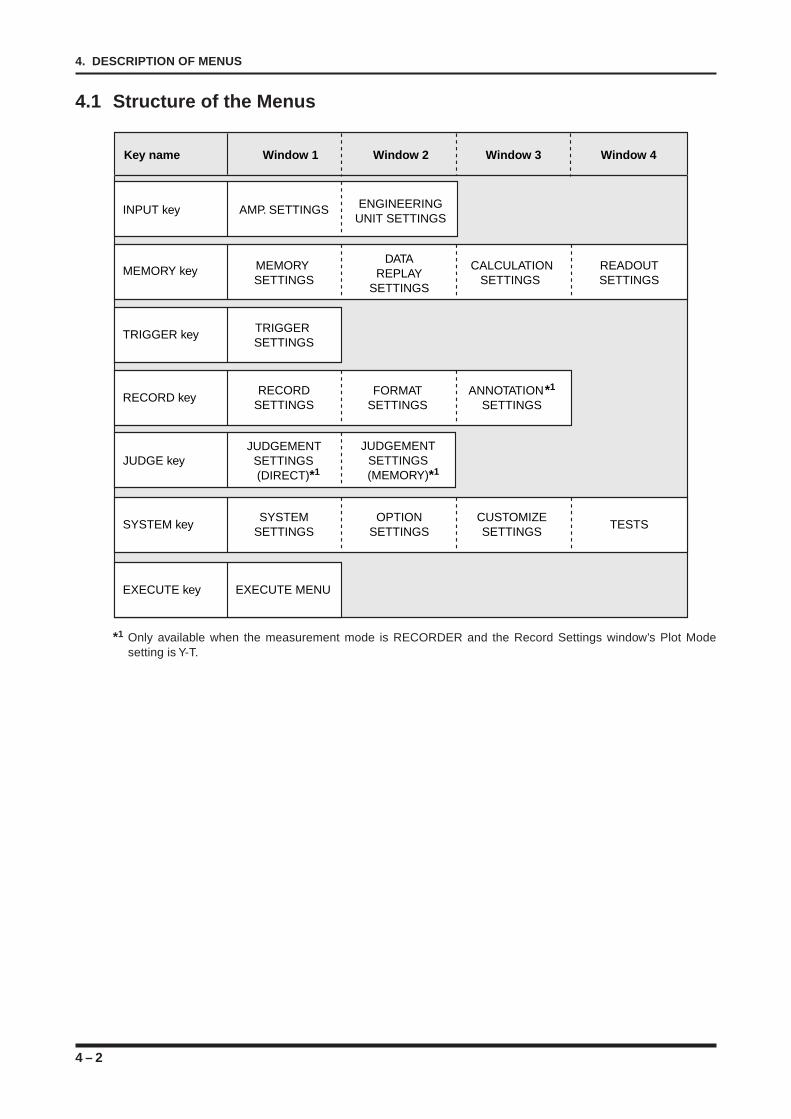
4 – 2
4. DESCRIPTION OF MENUS
4.1 Structure of the Menus
Key name Window 1 Window 2 Window 3 Window 4
INPUT key AMP. SETTINGS ENGINEERINGUNIT SETTINGS
MEMORY key MEMORY SETTINGS
DATAREPLAY
SETTINGS
CALCULATIONSETTINGS
RECORD keyRECORD
SETTINGSFORMAT
SETTINGS
JUDGE keyJUDGEMENT
SETTINGS (DIRECT)*1
JUDGEMENTSETTINGS(MEMORY)*1
ANNOTATION*1 SETTINGS
READOUTSETTINGS
SYSTEM keySYSTEM
SETTINGSOPTION
SETTINGSCUSTOMIZESETTINGS
TESTS
TRIGGER key TRIGGER SETTINGS
EXECUTE key EXECUTE MENU
*1 Only available when the measurement mode is RECORDER and the Record Settings window’s Plot Modesetting is Y-T.
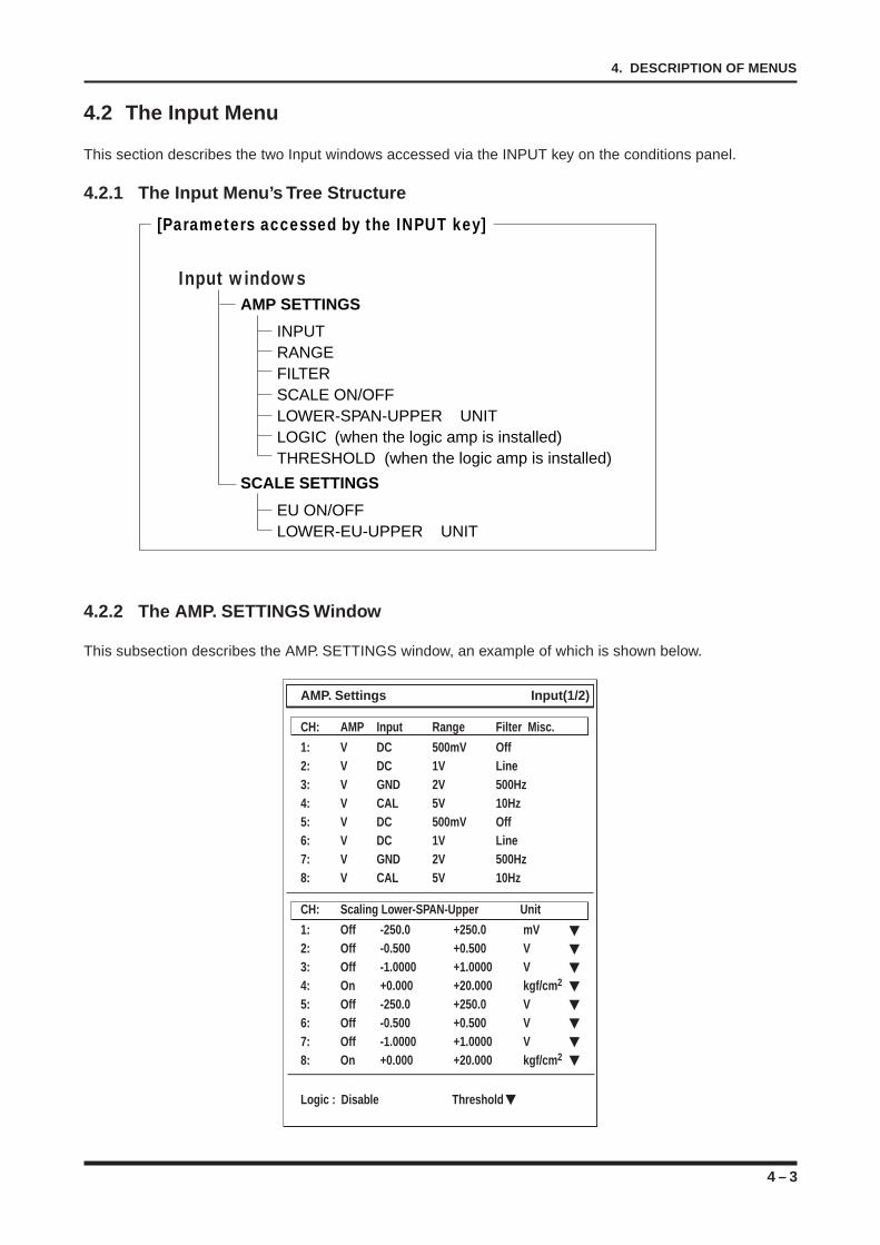
4 – 3
4. DESCRIPTION OF MENUS
4.2 The Input Menu
This section describes the two Input windows accessed via the INPUT key on the conditions panel.
4.2.1 The Input Menu’s Tree Structure
AMP SETTINGS
SCALE SETTINGS
INPUT RANGE FILTER SCALE ON/OFF LOWER-SPAN-UPPER UNITLOGIC (when the logic amp is installed)THRESHOLD (when the logic amp is installed)
EU ON/OFFLOWER-EU-UPPER UNIT
Input windows
[Parameters accessed by the INPUT key]
4.2.2 The AMP. SETTINGS Window
This subsection describes the AMP. SETTINGS window, an example of which is shown below.
AMP. Settings Input(1/2)
CH: AMP Input Range Filter Misc.
1: V DC 500mV Off2: V DC 1V Line3: V GND 2V 500Hz4: V CAL 5V 10Hz5: V DC 500mV Off6: V DC 1V Line7: V GND 2V 500Hz8: V CAL 5V 10Hz
CH: Scaling Lower-SPAN-Upper Unit
1: Off -250.0 +250.0 mV2: Off -0.500 +0.500 V3: Off -1.0000 +1.0000 V4: On +0.000 +20.000 kgf/cm2
5: Off -250.0 +250.0 V6: Off -0.500 +0.500 V7: Off -1.0000 +1.0000 V8: On +0.000 +20.000 kgf/cm2
Logic : Disable Threshold
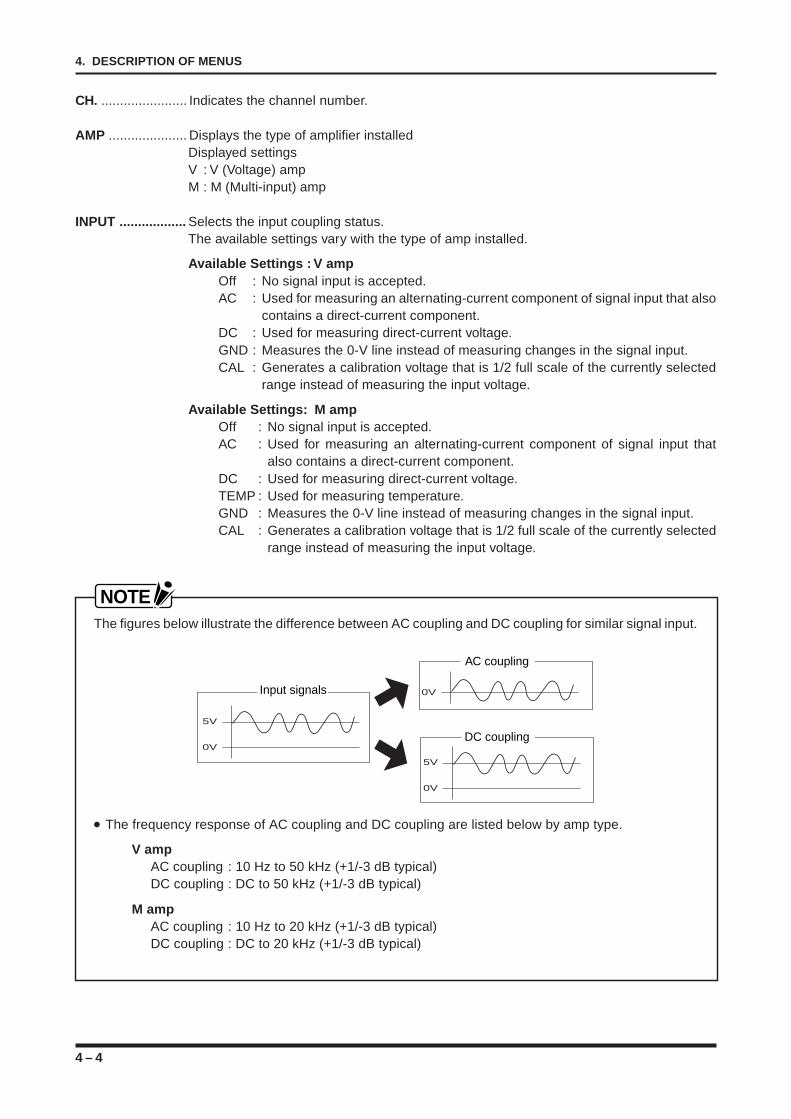
4 – 4
4. DESCRIPTION OF MENUS
CH. ....................... Indicates the channel number.
AMP ..................... Displays the type of amplifier installedDisplayed settingsV : V (Voltage) ampM : M (Multi-input) amp
INPUT .................. Selects the input coupling status.The available settings vary with the type of amp installed.
Available Settings : V ampOff : No signal input is accepted.AC : Used for measuring an alternating-current component of signal input that also
contains a direct-current component.DC : Used for measuring direct-current voltage.GND : Measures the 0-V line instead of measuring changes in the signal input.CAL : Generates a calibration voltage that is 1/2 full scale of the currently selected
range instead of measuring the input voltage.
Available Settings: M ampOff : No signal input is accepted.AC : Used for measuring an alternating-current component of signal input that
also contains a direct-current component.DC : Used for measuring direct-current voltage.TEMP : Used for measuring temperature.GND : Measures the 0-V line instead of measuring changes in the signal input.CAL : Generates a calibration voltage that is 1/2 full scale of the currently selected
range instead of measuring the input voltage.
NOTEThe figures below illustrate the difference between AC coupling and DC coupling for similar signal input.
5V
0V
0V
5V
0V
Input signals
AC coupling
DC coupling
The frequency response of AC coupling and DC coupling are listed below by amp type.
V ampAC coupling : 10 Hz to 50 kHz (+1/-3 dB typical)DC coupling : DC to 50 kHz (+1/-3 dB typical)
M ampAC coupling : 10 Hz to 20 kHz (+1/-3 dB typical)DC coupling : DC to 20 kHz (+1/-3 dB typical)
4 – 5
4. DESCRIPTION OF MENUS
RANGE ................ Specifies the range of signal input to be measured.The available settings vary with the type of amp installed and the INPUT setting.
Available Settings : V amp50mV, 100mV, 200mV, 500mV, 1V, 2V, 5V, 10V, 20V, 50V, 100V, 200V, 500V, AUTO
Available Settings : M amp• Input setting is AC or DC
20mV, 50mV, 100mV, 200mV, 500mV, 1V, 2V, 5V, 10V, 20V, 50V, 100V, 200V, 500V,AUTO
• Input setting is TEMPTC-K, TC-J, TC-T, TC-R, TC-E, TC-B
NOTEWhen the AUTO setting is selected, the measurement range is automatically selected to suit the signalinput. The selected range is determined by the input voltage level at the time the AUTO setting isselected.
FILTER ................. Selects the filter status.
Available SettingsOff, Line, 5Hz, 10Hz, 30Hz, 50Hz, 500Hz, 5kHz
NOTE• Use the Line filter setting to cut off noise (50/60 Hz) from the power line when such noise is affecting
the signal input.• The 5Hz to 5kHz settings each correspond to a lowpass filter, which cuts off signals of a frequency
higher than the frequency specified by the FILTER setting. The setting of each lowpass filter is -3 dB(typical).
MISC. ................... Additional settings may be required according to the type of amp installed.Specify the additional settings as necessary.
SCALING ............. Displays the current setting of the SCALE function on the ENGINEERING UNIT SETTINGSwindow.
NOTEThe SCALE parameter in the AMP. SETTINGS window merely displays the status of the ENGINEER-ING UNIT SETTINGS window’s SCALE function, which can only be changed at the ENGINEERINGUNIT SETTINGS window.
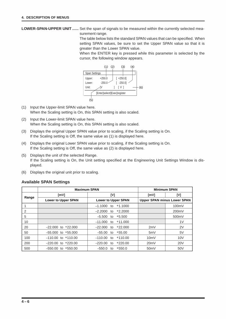
4 – 6
4. DESCRIPTION OF MENUS
LOWER-SPAN-UPPER UNIT ...... Set the span of signals to be measured within the currently selected mea-surement range.The table below lists the standard SPAN values that can be specified. Whensetting SPAN values, be sure to set the Upper SPAN value so that it isgreater than the Lower SPAN value.When the ENTER key is pressed while this parameter is selected by thecursor, the following window appears.
[Enter]select/[Exec]register
Span Settings
Upper: +250.0 [ +250.0]
Lower: -250.0 [ -250.0]
Unit: [V ] [ V ]
(1)
(5)
(6)
(2) (3) (4)
(1) Input the Upper-limit SPAN value here.When the Scaling setting is On, this SPAN setting is also scaled.
(2) Input the Lower-limit SPAN value here.When the Scaling setting is On, this SPAN setting is also scaled.
(3) Displays the original Upper SPAN value prior to scaling, if the Scaling setting is On.If the Scaling setting is Off, the same value as (1) is displayed here.
(4) Displays the original Lower SPAN value prior to scaling, if the Scaling setting is On.If the Scaling setting is Off, the same value as (2) is displayed here.
(5) Displays the unit of the selected Range.If the Scaling setting is On, the Unit setting specified at the Engineering Unit Settings Window is dis-played.
(6) Displays the original unit prior to scaling.
Available SPAN Settings
Maximum SPAN Minimum SPAN
[mV] [V] [mV] [V]
Lower to Upper SPAN Lower to Upper SPAN Upper SPAN minus Lower SPAN
1 –1.1000 to +1.1000 100mV
2 –2.2000 to +2.2000 200mV
5 –5.500 to +5.500 500mV
10 –11.000 to +11.000 1V
20 –22.000 to +22.000 –22.000 to +22.000 2mV 2V
50 –55.000 to +55.000 –55.00 to +55.00 5mV 5V
100 –110.00 to +110.00 –110.00 to +110.00 10mV 10V
200 –220.00 to +220.00 –220.00 to +220.00 20mV 20V
500 –550.00 to +550.00 –550.0 to +550.0 50mV 50V
Range
4 – 7
4. DESCRIPTION OF MENUS
Maximum SPAN Minimum SPAN
Range Lower to Upper SPAN Upper SPAN minus Lower SPAN
K –200.0 to +1300.0 50°CJ –200.0 to +1100.0 50°CT –200.0 to +400.0 50°CR 0.0 to +1600.0 50°CE –200.0 to +800.0 50°CB 600.0 to +1700.0 50°C
NOTEThe span can be physically set to anywhere between -270.0°C to +2000°C regardless of the tempera-ture range that has been set. However, the actual span that can be used for each range is shown in theabove table.
NOTE• The AMP. SETTINGS window cannot display the SPAN settings of a channel for which the FUNC-
TION setting (in the CALCULATION SETTINGS window) is On. To set the SPAN settings for such achannel, use the LOWER-CALC SPAN-UPPER parameters in the Memory menu’s CALCULATIONSETTINGS window.
• The UNIT parameter in the AMP. SETTINGS window cannot be used to change the UNIT setting.
LOGIC .................. This parameter, which can only be set when the channels are equipped with a logic amp,selects the On/Off status for using the logic amp.
Available SettingsOff : Disables use of the logic amp.On : Enables use of the logic amp.
NOTE• The recording and display of logic signals in RECORDER mode can be enabled when the Logic
setting is ON and the Logic Zone setting of the Format Settings window is also ON.• The recording and display of logic signals in LOGGING mode are synchronized with the current Logic
setting.
THRESHOLD LEVEL ..... This parameter, which can only be set when the channels are equipped with a logicamp, specifies a high or low threshold level for logic signals.
Available Settings+1.4V (TTL) : Regards the input of logic signals with a voltage level of about
1.4 V or higher as the High threshold level.+2.5V (CMOS) : Regards the input of logic signals with a voltage level of about
2.5 V or higher as the High threshold level.+5.0V (contact point) : Regards the input of logic signals with a voltage level of about
5.0 V or higher as the High threshold level.
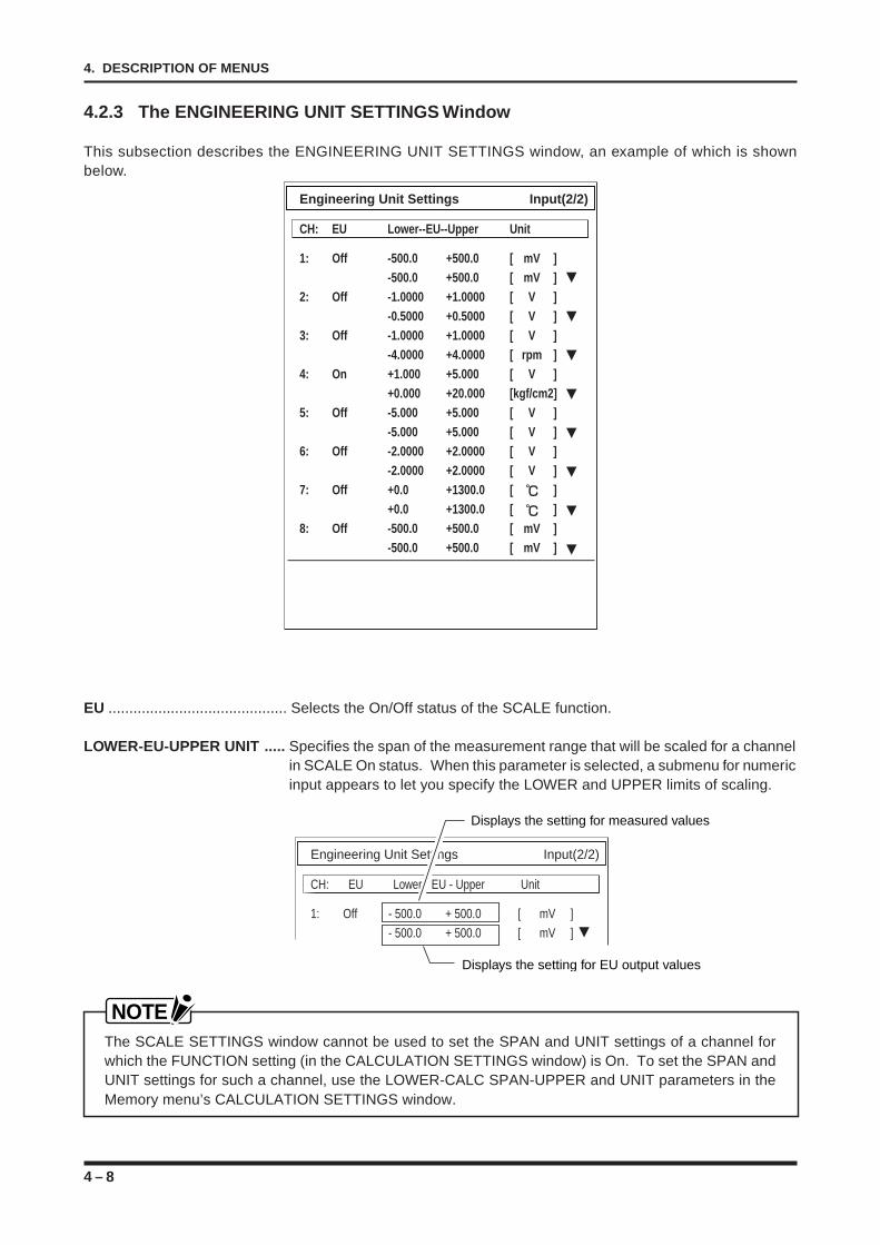
4 – 8
4. DESCRIPTION OF MENUS
4.2.3 The ENGINEERING UNIT SETTINGS Window
This subsection describes the ENGINEERING UNIT SETTINGS window, an example of which is shownbelow.
Engineering Unit Settings Input(2/2)
CH: EU Lower--EU--Upper Unit
1: Off -500.0 +500.0 [ mV ]-500.0 +500.0 [ mV ]
2: Off -1.0000 +1.0000 [ V ]-0.5000 +0.5000 [ V ]
3: Off -1.0000 +1.0000 [ V ]-4.0000 +4.0000 [ rpm ]
4: On +1.000 +5.000 [ V ]+0.000 +20.000 [kgf/cm2]
5: Off -5.000 +5.000 [ V ]-5.000 +5.000 [ V ]
6: Off -2.0000 +2.0000 [ V ]-2.0000 +2.0000 [ V ]
7: Off +0.0 +1300.0 [ ]+0.0 +1300.0 [ ]
8: Off -500.0 +500.0 [ mV ]-500.0 +500.0 [ mV ]
EU ........................................... Selects the On/Off status of the SCALE function.
LOWER-EU-UPPER UNIT ..... Specifies the span of the measurement range that will be scaled for a channelin SCALE On status. When this parameter is selected, a submenu for numericinput appears to let you specify the LOWER and UPPER limits of scaling.
Engineering Unit Settings Input(2/2)
CH: EU Lower - EU - Upper Unit
1: Off - 500.0 + 500.0 [ mV ]
- 500.0 + 500.0 [ mV ]
Displays the setting for EU output values
Displays the setting for measured values
NOTEThe SCALE SETTINGS window cannot be used to set the SPAN and UNIT settings of a channel forwhich the FUNCTION setting (in the CALCULATION SETTINGS window) is On. To set the SPAN andUNIT settings for such a channel, use the LOWER-CALC SPAN-UPPER and UNIT parameters in theMemory menu’s CALCULATION SETTINGS window.
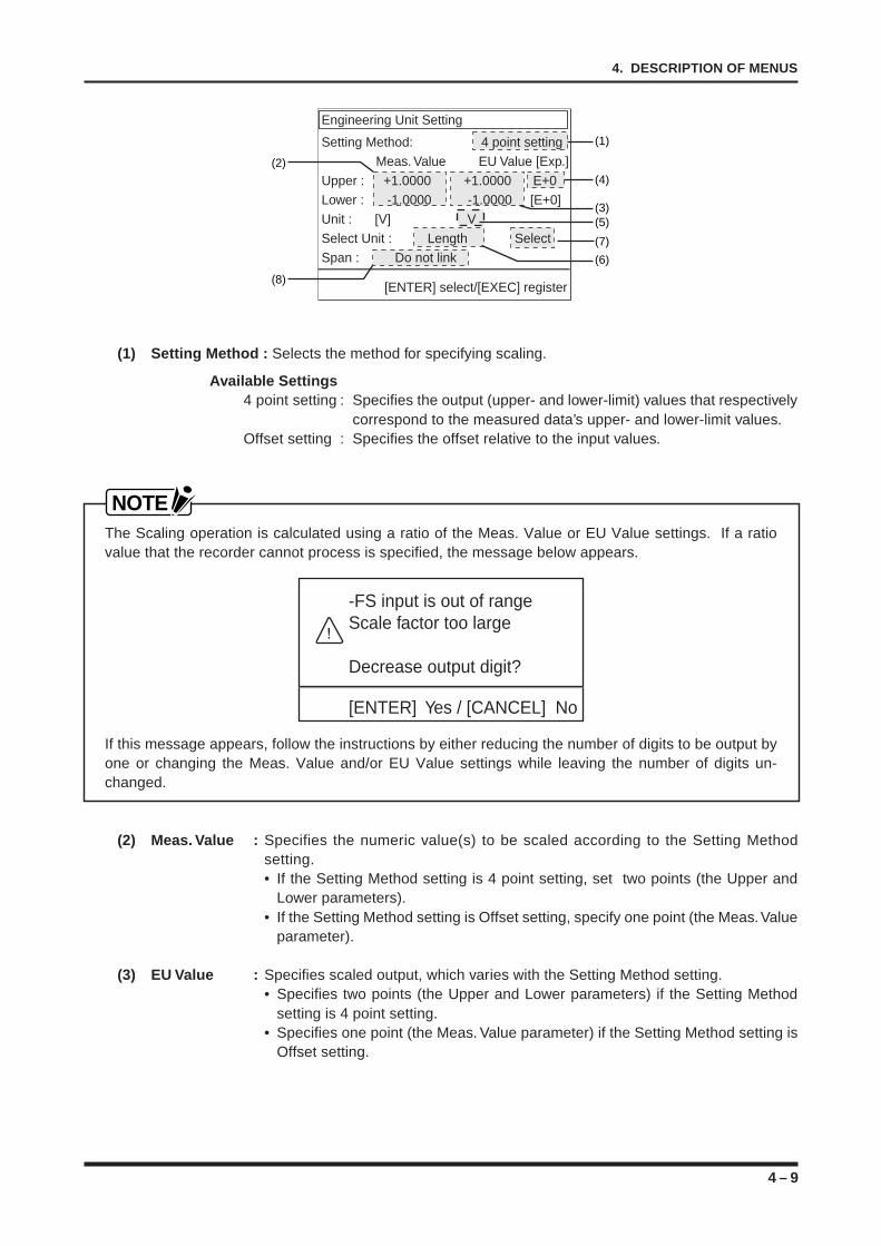
4 – 9
4. DESCRIPTION OF MENUS
Engineering Unit Setting
Setting Method: 4 point setting Meas. Value EU Value [Exp.]Upper : +1.0000 +1.0000 E+0Lower : -1.0000 -1.0000 [E+0]Unit : [V] VSelect Unit : Length SelectSpan : Do not link
[ENTER] select/[EXEC] register
(1)
(2)
(8)
(4)
(3)(5)
(7)
(6)
(1) Setting Method : Selects the method for specifying scaling.
Available Settings4 point setting : Specifies the output (upper- and lower-limit) values that respectively
correspond to the measured data’s upper- and lower-limit values.Offset setting : Specifies the offset relative to the input values.
NOTEThe Scaling operation is calculated using a ratio of the Meas. Value or EU Value settings. If a ratiovalue that the recorder cannot process is specified, the message below appears.
-FS input is out of rangeScale factor too large
Decrease output digit?
[ENTER] Yes / [CANCEL] No
If this message appears, follow the instructions by either reducing the number of digits to be output byone or changing the Meas. Value and/or EU Value settings while leaving the number of digits un-changed.
(2) Meas. Value : Specifies the numeric value(s) to be scaled according to the Setting Methodsetting.• If the Setting Method setting is 4 point setting, set two points (the Upper and
Lower parameters).• If the Setting Method setting is Offset setting, specify one point (the Meas. Value
parameter).
(3) EU Value : Specifies scaled output, which varies with the Setting Method setting.• Specifies two points (the Upper and Lower parameters) if the Setting Method
setting is 4 point setting.• Specifies one point (the Meas. Value parameter) if the Setting Method setting is
Offset setting.
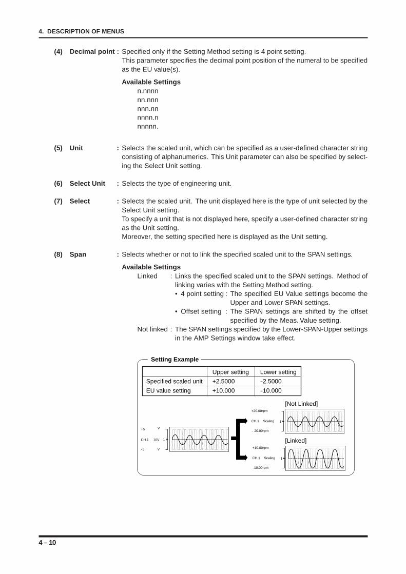
4 – 10
4. DESCRIPTION OF MENUS
(4) Decimal point : Specified only if the Setting Method setting is 4 point setting.This parameter specifies the decimal point position of the numeral to be specifiedas the EU value(s).
Available Settingsn.nnnnnn.nnnnnn.nnnnnn.nnnnnn.
(5) Unit : Selects the scaled unit, which can be specified as a user-defined character stringconsisting of alphanumerics. This Unit parameter can also be specified by select-ing the Select Unit setting.
(6) Select Unit : Selects the type of engineering unit.
(7) Select : Selects the scaled unit. The unit displayed here is the type of unit selected by theSelect Unit setting.To specify a unit that is not displayed here, specify a user-defined character stringas the Unit setting.Moreover, the setting specified here is displayed as the Unit setting.
(8) Span : Selects whether or not to link the specified scaled unit to the SPAN settings.
Available SettingsLinked : Links the specified scaled unit to the SPAN settings. Method of
linking varies with the Setting Method setting.• 4 point setting : The specified EU Value settings become the
Upper and Lower SPAN settings.• Offset setting : The SPAN settings are shifted by the offset
specified by the Meas. Value setting.Not linked : The SPAN settings specified by the Lower-SPAN-Upper settings
in the AMP Settings window take effect.
1CH.1 Scaling
+20.00rpm
- 20.00rpm
1CH.1 10V
+5
-5 V
V
1CH.1 Scaling
+10.00rpm
-10.00rpm
Setting Example
Upper setting Lower setting
Specified scaled unit +2.5000 -2.5000
EU value setting +10.000 -10.000
[Linked]
[Not Linked]
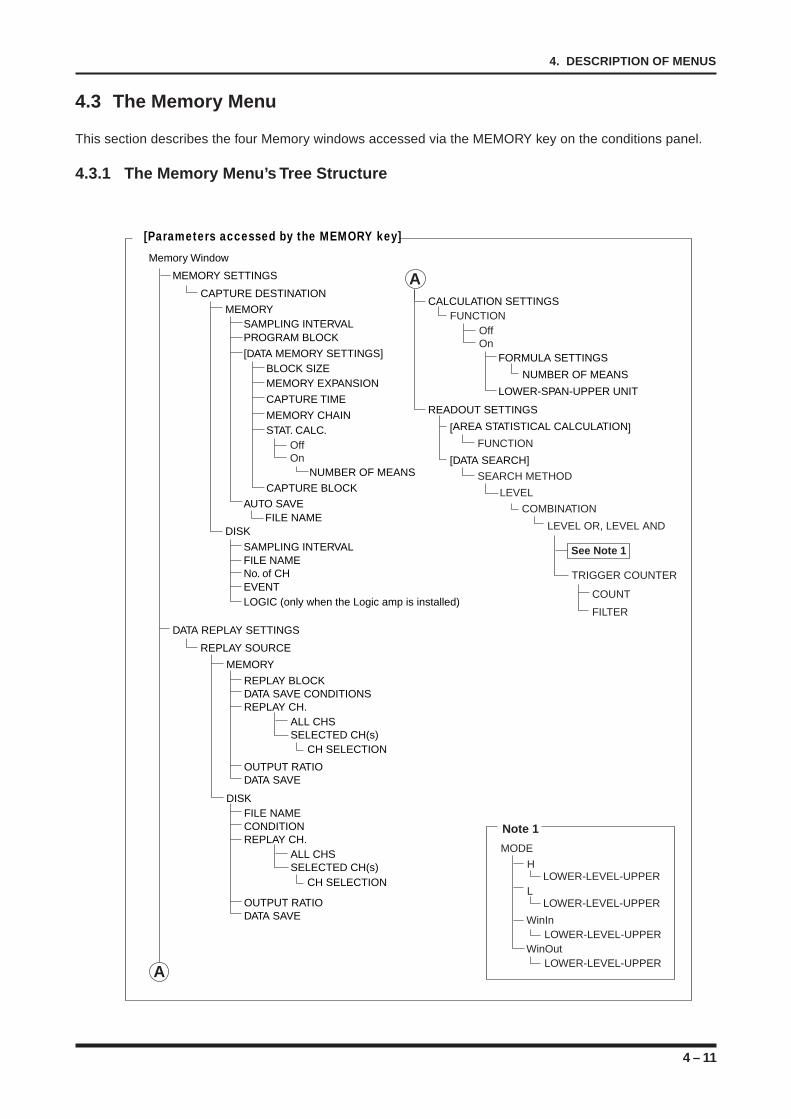
4 – 11
4. DESCRIPTION OF MENUS
4.3 The Memory Menu
This section describes the four Memory windows accessed via the MEMORY key on the conditions panel.
4.3.1 The Memory Menu’s Tree Structure
[Parameters accessed by the MEMORY key]
MEMORY SETTINGS
CAPTURE DESTINATION
MEMORY
DISK
SAMPLING INTERVALPROGRAM BLOCK
SAMPLING INTERVALFILE NAMENo. of CHEVENTLOGIC (only when the Logic amp is installed)
[DATA MEMORY SETTINGS]
AUTO SAVEFILE NAME
BLOCK SIZEMEMORY EXPANSION
CAPTURE TIME
MEMORY CHAIN
CAPTURE BLOCK
STAT. CALC.OffOn
NUMBER OF MEANS
OffOn
FORMULA SETTINGS
NUMBER OF MEANS
LOWER-SPAN-UPPER UNIT
DATA REPLAY SETTINGS
REPLAY SOURCE
MEMORY
REPLAY BLOCKDATA SAVE CONDITIONSREPLAY CH.
OUTPUT RATIODATA SAVE
ALL CHSSELECTED CH(s)
CH SELECTION
CALCULATION SETTINGS
AMemory Window
FUNCTION
MODE
LOWER-LEVEL-UPPER
LOWER-LEVEL-UPPER
WinInLOWER-LEVEL-UPPER
WinOutLOWER-LEVEL-UPPER
READOUT SETTINGS
[DATA SEARCH]
SEARCH METHOD
[AREA STATISTICAL CALCULATION]
FUNCTION
LEVEL OR, LEVEL AND
LEVEL
COMBINATION
COUNT
FILTER
TRIGGER COUNTER
See Note 1
Note 1
DISK FILE NAMECONDITIONREPLAY CH.
OUTPUT RATIODATA SAVE
ALL CHSSELECTED CH(s)
CH SELECTION
A
L
H
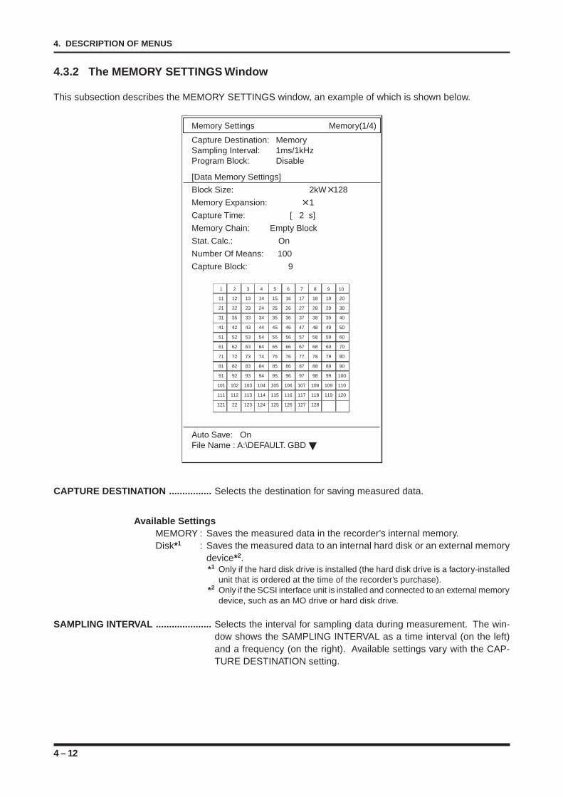
4 – 12
4. DESCRIPTION OF MENUS
4.3.2 The MEMORY SETTINGS Window
This subsection describes the MEMORY SETTINGS window, an example of which is shown below.
Memory Settings Memory(1/4)
Capture Destination: MemorySampling Interval: 1ms/1kHzProgram Block: Disable
[Data Memory Settings]
Block Size: 2kW 128
Memory Expansion: 1
Capture Time: [ 2 s]
Memory Chain: Empty Block
Stat. Calc.: On
Number Of Means: 100
Capture Block: 9
1 2 3 4 5 6 7 8 9 10
11 12 13 14 15 16 17 18 19 20
21 22 23 24 25 26 27 28 29 30
31 35 33 34 35 36 37 38 39 40
41 42 43 44 45 46 47 48 49 50
51 52 53 54 55 56 57 58 59 60
61 62 63 64 65 66 67 68 69 70
71 72 73 74 75 76 77 78 79 80
81 82 83 84 85 86 87 88 89 90
91 92 93 94 95 96 97 98 99 100
101 102 103 104 105 106 107 108 109 110
111 112 113 114 115 116 117 118 119 120
121 22 123 124 125 126 127 128
Auto Save: OnFile Name : A:\DEFAULT. GBD
CAPTURE DESTINATION ................ Selects the destination for saving measured data.
Available SettingsMEMORY : Saves the measured data in the recorder’s internal memory.Disk*1 : Saves the measured data to an internal hard disk or an external memory
device*2.*1 Only if the hard disk drive is installed (the hard disk drive is a factory-installed
unit that is ordered at the time of the recorder’s purchase).*2 Only if the SCSI interface unit is installed and connected to an external memory
device, such as an MO drive or hard disk drive.
SAMPLING INTERVAL ..................... Selects the interval for sampling data during measurement. The win-dow shows the SAMPLING INTERVAL as a time interval (on the left)and a frequency (on the right). Available settings vary with the CAP-TURE DESTINATION setting.
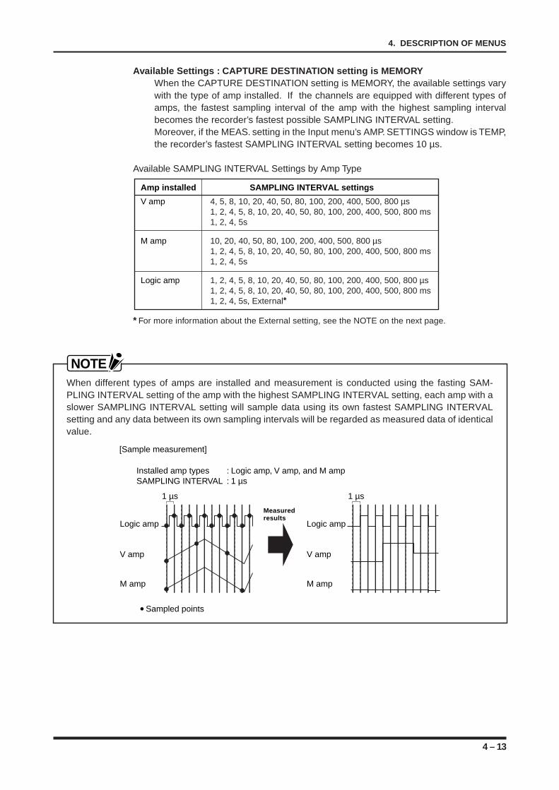
4 – 13
4. DESCRIPTION OF MENUS
Available Settings : CAPTURE DESTINATION setting is MEMORYWhen the CAPTURE DESTINATION setting is MEMORY, the available settings varywith the type of amp installed. If the channels are equipped with different types ofamps, the fastest sampling interval of the amp with the highest sampling intervalbecomes the recorder’s fastest possible SAMPLING INTERVAL setting.Moreover, if the MEAS. setting in the Input menu’s AMP. SETTINGS window is TEMP,the recorder’s fastest SAMPLING INTERVAL setting becomes 10 µs.
Available SAMPLING INTERVAL Settings by Amp Type
Amp installed SAMPLING INTERVAL settings
V amp 4, 5, 8, 10, 20, 40, 50, 80, 100, 200, 400, 500, 800 µs1, 2, 4, 5, 8, 10, 20, 40, 50, 80, 100, 200, 400, 500, 800 ms1, 2, 4, 5s
M amp 10, 20, 40, 50, 80, 100, 200, 400, 500, 800 µs1, 2, 4, 5, 8, 10, 20, 40, 50, 80, 100, 200, 400, 500, 800 ms1, 2, 4, 5s
Logic amp 1, 2, 4, 5, 8, 10, 20, 40, 50, 80, 100, 200, 400, 500, 800 µs1, 2, 4, 5, 8, 10, 20, 40, 50, 80, 100, 200, 400, 500, 800 ms1, 2, 4, 5s, External*
* For more information about the External setting, see the NOTE on the next page.
NOTEWhen different types of amps are installed and measurement is conducted using the fasting SAM-PLING INTERVAL setting of the amp with the highest SAMPLING INTERVAL setting, each amp with aslower SAMPLING INTERVAL setting will sample data using its own fastest SAMPLING INTERVALsetting and any data between its own sampling intervals will be regarded as measured data of identicalvalue.
Logic amp
V amp
M amp
Logic amp
V amp
M amp
Installed amp types : Logic amp, V amp, and M ampSAMPLING INTERVAL : 1 µs
1 µs
Measured results
[Sample measurement]
• Sampled points
1 µs
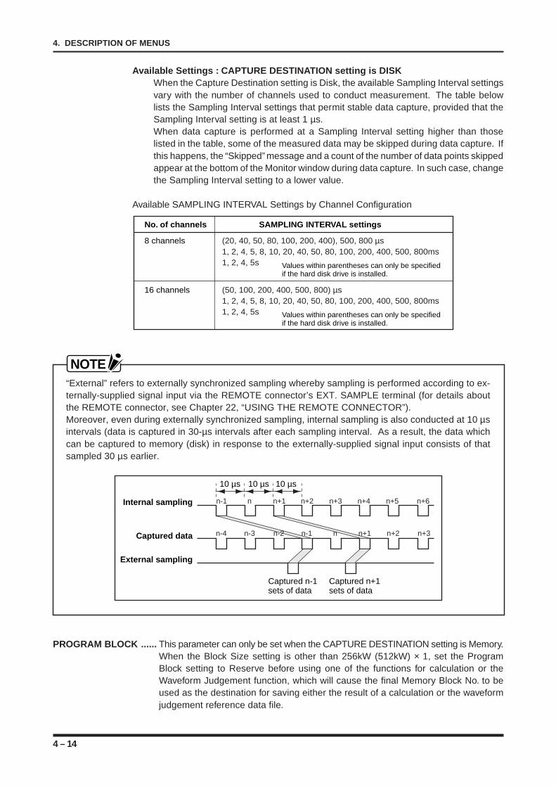
4 – 14
4. DESCRIPTION OF MENUS
Available Settings : CAPTURE DESTINATION setting is DISKWhen the Capture Destination setting is Disk, the available Sampling Interval settingsvary with the number of channels used to conduct measurement. The table belowlists the Sampling Interval settings that permit stable data capture, provided that theSampling Interval setting is at least 1 µs.When data capture is performed at a Sampling Interval setting higher than thoselisted in the table, some of the measured data may be skipped during data capture. Ifthis happens, the “Skipped” message and a count of the number of data points skippedappear at the bottom of the Monitor window during data capture. In such case, changethe Sampling Interval setting to a lower value.
Available SAMPLING INTERVAL Settings by Channel Configuration
No. of channels SAMPLING INTERVAL settings
8 channels (20, 40, 50, 80, 100, 200, 400), 500, 800 µs1, 2, 4, 5, 8, 10, 20, 40, 50, 80, 100, 200, 400, 500, 800ms1, 2, 4, 5s Values within parentheses can only be specified
if the hard disk drive is installed.
16 channels (50, 100, 200, 400, 500, 800) µs1, 2, 4, 5, 8, 10, 20, 40, 50, 80, 100, 200, 400, 500, 800ms1, 2, 4, 5s Values within parentheses can only be specified
if the hard disk drive is installed.
NOTE“External” refers to externally synchronized sampling whereby sampling is performed according to ex-ternally-supplied signal input via the REMOTE connector’s EXT. SAMPLE terminal (for details aboutthe REMOTE connector, see Chapter 22, “USING THE REMOTE CONNECTOR”).Moreover, even during externally synchronized sampling, internal sampling is also conducted at 10 µsintervals (data is captured in 30-µs intervals after each sampling interval. As a result, the data whichcan be captured to memory (disk) in response to the externally-supplied signal input consists of thatsampled 30 µs earlier.
n-1Internal sampling
Captured data
External sampling
Captured n-1 sets of data
Captured n+1 sets of data
n n+1 n+2 n+3 n+4 n+5 n+6
n+2 n+3n-4 n-3 n-2 n-1 n n+1
10 µs 10 µs 10 µs
PROGRAM BLOCK ...... This parameter can only be set when the CAPTURE DESTINATION setting is Memory.When the Block Size setting is other than 256kW (512kW) × 1, set the ProgramBlock setting to Reserve before using one of the functions for calculation or theWaveform Judgement function, which will cause the final Memory Block No. to beused as the destination for saving either the result of a calculation or the waveformjudgement reference data file.
4 – 15
4. DESCRIPTION OF MENUS
NOTEWhen the Program Block setting is Reserve, even if the final Memory Block No. contains data, suchdata will be overwritten.
BLOCK SIZE ....... This parameter, which can only be set when the CAPTURE DESTINATION setting isMEMORY, selects the number of blocks in the recorder’s internal memory. By partitioningthe internal memory according to the amount of time spent on measurement, you canchange the capacity of the internal memory.
Available SettingsFor the standard memory unit (256 kWords/channel)
256 kWords × 1, 128 kWords × 2, 64 kWords × 4, 32 kWords × 8, 16 kWords × 16,8 kWords × 32, 4 kWords × 64, 2 kWords × 128
For the optional memory unit (512 kWords/channel)512 kWords × 1, 256 kWords × 2, 128 kWords × 4, 64 kWords × 8, 32 kWords × 16,16 kWords × 32, 8 kWords × 64, 4 kWords × 128
NOTEThe WR1000 has an internal memory capacity equivalent to 256 kWords per channel with the standardmemory unit, or 512 kWords per channel with the add-on memory unit. The block sizes listed aboverepresent the amount of memory allocated to each channel.
MEMORY EXPANSION ...... This parameter, which can only be set when the CAPTURE DESTINATION settingis MEMORY, selects the expansion rate for allocating the recorder’s internal memory.This function lets you allocate the memory assigned to unused channels to thechannels you intend to use.
Available Settings
No. of MEMORY Standard memory (256 kW/CH) Add-on memory (512 kW/CH)channels EXPANSION Usable channels/ Usable channels/
setting memory per channel memory per channel
8 × 1 Channel 1 to 8/256 kWords Channel 1 to 8/512 kWords
× 2 Channel 1 to 4/512 kWords Channel 1 to 4/1024 kWords
× 4 Channel 1 & 2/1024 kWords Channel 1 & 2/2048 kWords
× 8 1 CH only/2048 kWords 1 CH only/4096 kWords
16 × 1 Channel 1 to 16/256 kWords Channel 1 to 16/512 kWords
× 2 Channel 1 to 4 and 9 to 12/512 kWords Channel 1 to 4 and 9 to 12/1024 kWords
× 4 Channel 1, 2, 9 & 10/1024 kWords Channel 1, 2, 9 & 10/2048 kWords
× 8 Channel 1 & 9/2048 kWords Channel 1 & 9/4096 kWords
CAPTURE TIME ............ This parameter, which is only displayed when the CAPTURE DESTINATION settingis MEMORY, indicates the time required for capturing data in the recorder’s internalmemory. The total time equals the SAMPLING INTERVAL setting multiplied by theBLOCK SIZE and MEMORY EXPANSION settings.
Example:SAMPLING INTERVAL : 4 µsBLOCK SIZE : 2 kW × 128MEMORY EXPANSION : × 1CAPTURE TIME : 2 kW × 4 µs = 8 ms
4 – 16
4. DESCRIPTION OF MENUS
MEMORY CHAIN........... This parameter, which can only be set when the CAPTURE DESTINATION setting isMEMORY, selects the method for capturing data in partitioned memory blocks.
Available SettingsOff : Repeatedly captures data to the specified Block No.SEQUENTIAL BLOCK : Repeatedly captures and overwrites data in ascending
order from the specified Block No. (proceeding to Block 1after the highest Block No.) until measurement is completed.
EMPTY BLOCK : Captures data in ascending order from the specified BlockNo. (proceeding to Block 1 after the highest Block No.),terminating data capture when no empty blocks remain.
NOTEA block containing data and an empty block can be distinguished by the color used to display theirBlock No.
Green : A block containing data.Gray : An empty blockBlue : A block containing the result of a calculation operation and so forth.
STAT. CALC. ........ This parameter selects the On/Off status of statistical calculation, provided that both of thefollowing conditions are met:• The Capture Destination setting is Memory; and• The Block Size setting is other than 256kW (512kW) × 1.
Arithmetic averaging is used as the method for statistical calculation. Statistical calculationcalculates the arithmetic mean between the data captured in the specified Memory Block(which varies with the Memory Chain and Memory Block settings) and the data captured atthe final Block No., and then saves the calculated result at the final Block No.This operation is performed the number of times specified by the Number of Means param-eter.
Available SettingsOff : Disables statistical calculation.On : Enables statistical calculation. When On is selected, a submenu appears for
setting the frequency of arithmetic averaging.
NOTE• The result of a Stat. Calc. operation will be stored at the last Memory Block No.• Data saved in the specified Memory Block is constantly overwritten so that only the most recent data
is stored. Please note that earlier data will not be retained.
Number of Means : Sets the number of elements to be used for calculating the arithmeticmean. The permissible range of this setting is 1 to 128.
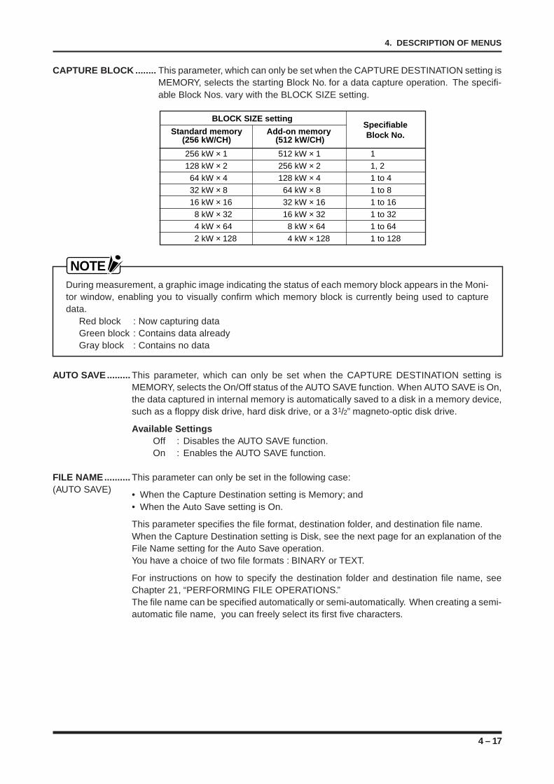
4 – 17
4. DESCRIPTION OF MENUS
CAPTURE BLOCK ........ This parameter, which can only be set when the CAPTURE DESTINATION setting isMEMORY, selects the starting Block No. for a data capture operation. The specifi-able Block Nos. vary with the BLOCK SIZE setting.
BLOCK SIZE setting Standard memory Add-on memory
Specifiable
(256 kW/CH) (512 kW/CH) Block No.
256 kW × 1 512 kW × 1 1128 kW × 2 256 kW × 2 1, 2 64 kW × 4 128 kW × 4 1 to 4 32 kW × 8 64 kW × 8 1 to 8 16 kW × 16 32 kW × 16 1 to 16
8 kW × 32 16 kW × 32 1 to 32 4 kW × 64 8 kW × 64 1 to 64
2 kW × 128 4 kW × 128 1 to 128
NOTEDuring measurement, a graphic image indicating the status of each memory block appears in the Moni-tor window, enabling you to visually confirm which memory block is currently being used to capturedata.
Red block : Now capturing dataGreen block : Contains data alreadyGray block : Contains no data
AUTO SAVE......... This parameter, which can only be set when the CAPTURE DESTINATION setting isMEMORY, selects the On/Off status of the AUTO SAVE function. When AUTO SAVE is On,the data captured in internal memory is automatically saved to a disk in a memory device,such as a floppy disk drive, hard disk drive, or a 31/2” magneto-optic disk drive.
Available SettingsOff : Disables the AUTO SAVE function.On : Enables the AUTO SAVE function.
FILE NAME.......... This parameter can only be set in the following case:(AUTO SAVE) • When the Capture Destination setting is Memory; and
• When the Auto Save setting is On.
This parameter specifies the file format, destination folder, and destination file name.When the Capture Destination setting is Disk, see the next page for an explanation of theFile Name setting for the Auto Save operation.You have a choice of two file formats : BINARY or TEXT.
For instructions on how to specify the destination folder and destination file name, seeChapter 21, “PERFORMING FILE OPERATIONS.”The file name can be specified automatically or semi-automatically. When creating a semi-automatic file name, you can freely select its first five characters.
4 – 18
4. DESCRIPTION OF MENUS
FILE NAME............... This parameter can only be specified in the following case:(DISK) • Either a hard disk drive or MO drive is installed as an internal memory device, or the
SCSI interface unit is installed and connected to an external memory device; and• The Capture Destination setting is Disk.
This parameter specifies the data format, destination folder, and destination file name.When the Capture Destination setting is Memory, see the previous page for an explana-tion of the File Name setting for the Auto Save operation.For instructions on how to specify the destination folder and destination file name, seeChapter 21, “PERFORMING FILE OPERATIONS.”
NUMBER OF CH ...... This parameter can only be specified in the following case:• Either a hard disk drive or MO drive is installed as an internal memory device, or an
external memory device is connected via the SCSI interface unit; and• The Capture Destination setting is Disk.
This parameter selects the target number of channels to be involved in data capture toa disk either in an internal memory device (a hard disk drive or MO drive), or in anexternal memory device connected via the SCSI interface unit. The Number of CHsetting represents the total number of channels, starting from CH. 1.
Available Settings8-channel model : 1, 2, 3, 4, 5, 6, 7, 816-channel model : 1, 2, 3, 4, 5, 6, 7, 8, 9, 10, 11, 12, 13, 14, 15, 16
NOTEIn some cases, it is possible to raise the maximum Sampling Interval by reducing the target number ofchannels.
EVENT ................. This parameter can only be specified in the following case:
• Either a hard disk drive or MO drive is installed as an internal memory device, or anexternal memory device is connected via the SCSI interface unit; and
• The Capture Destination setting is Disk.
This parameter enables or disables the simultaneous capture of Event Marker printingdata along with data capture to a disk either in an internal memory device (a hard disk driveor MO drive) or in an external memory device connected via the SCSI interface unit.
Event marker input is based on a logical OR operation between input via the REMOTEinterface or input by the main control panel’s MODE/EVENT key.
Available SettingsOff : Disables the capture of Event Marker data.On : Enables the capture of Event Marker data.
LOGIC .................. This parameter can only be specified in the following case:• Either a hard disk drive or MO drive is installed as an internal memory device, or an
external memory device is connected via the SCSI interface unit;• The Capture Destination setting is Disk; and• The Logic setting at the AMP Settings window is Enable.
This parameter enables or disables the simultaneous saving of logic data while saving theanalog amp data to a disk in either an internal memory device or external memory deviceconnected via the SCSI interface unit.
Available SettingsOff : Disables the saving of logic data.On : Enables the saving of logic data.
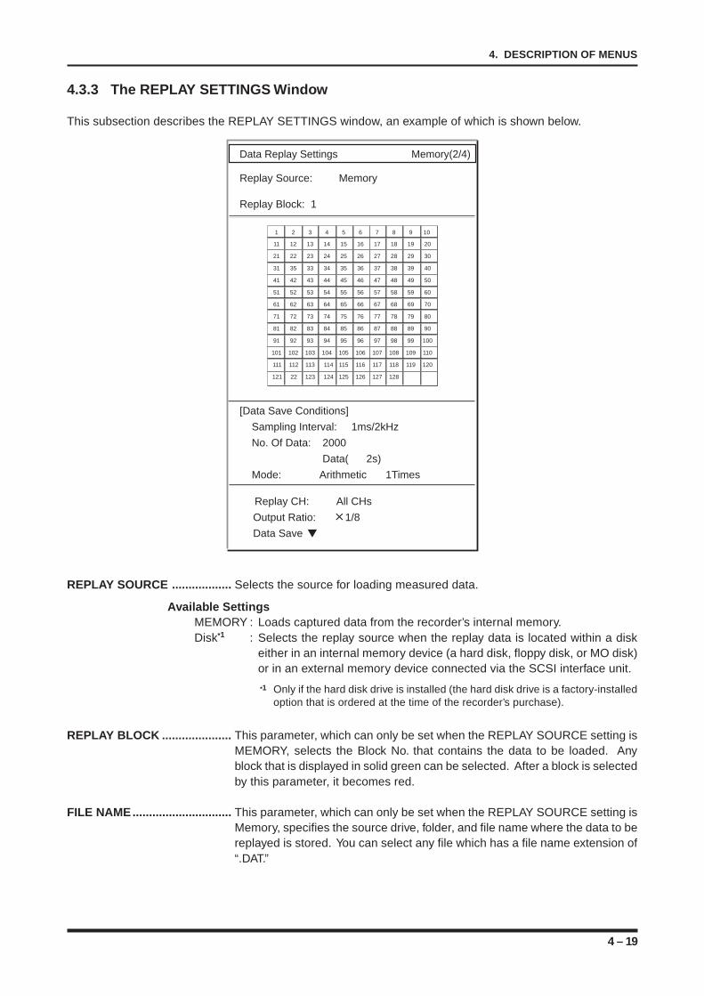
4 – 19
4. DESCRIPTION OF MENUS
4.3.3 The REPLAY SETTINGS Window
This subsection describes the REPLAY SETTINGS window, an example of which is shown below.
Data Replay Settings Memory(2/4)
Replay Source: Memory
Replay Block: 1
1 2 3 4 5 6 7 8 9 10
11 12 13 14 15 16 17 18 19 20
21 22 23 24 25 26 27 28 29 30
31 35 33 34 35 36 37 38 39 40
41 42 43 44 45 46 47 48 49 50
51 52 53 54 55 56 57 58 59 60
61 62 63 64 65 66 67 68 69 70
71 72 73 74 75 76 77 78 79 80
81 82 83 84 85 86 87 88 89 90
91 92 93 94 95 96 97 98 99 100
101 102 103 104 105 106 107 108 109 110
111 112 113 114 115 116 117 118 119 120
121 22 123 124 125 126 127 128
[Data Save Conditions]
Sampling Interval: 1ms/2kHz
No. Of Data: 2000
Data( 2s)
Mode: Arithmetic 1Times
Replay CH: All CHs
Output Ratio: 1/8
Data Save
REPLAY SOURCE .................. Selects the source for loading measured data.
Available SettingsMEMORY : Loads captured data from the recorder’s internal memory.Disk*1 : Selects the replay source when the replay data is located within a disk
either in an internal memory device (a hard disk, floppy disk, or MO disk)or in an external memory device connected via the SCSI interface unit.
*1 Only if the hard disk drive is installed (the hard disk drive is a factory-installedoption that is ordered at the time of the recorder’s purchase).
REPLAY BLOCK ..................... This parameter, which can only be set when the REPLAY SOURCE setting isMEMORY, selects the Block No. that contains the data to be loaded. Anyblock that is displayed in solid green can be selected. After a block is selectedby this parameter, it becomes red.
FILE NAME.............................. This parameter, which can only be set when the REPLAY SOURCE setting isMemory, specifies the source drive, folder, and file name where the data to bereplayed is stored. You can select any file which has a file name extension of“.DAT.”
4 – 20
4. DESCRIPTION OF MENUS
[DATA SAVE CONDITIONS] ... Displays the conditions that were used to save the data being loaded. Theconditions appear as soon as the REPLAY BLOCK setting is specified. Thedisplayed data cannot be changed.
SAMPLING INTERVAL : Displays the SAMPLING INTERVAL setting used to save the data being loaded.The displayed data cannot be changed.
NO. OF DATA : Displays the NO. OF DATA points used to save the data being loaded. Thedisplayed data cannot be changed.
MODE : During data capture, this displays the current settings of the Statistical Calcu-lation (Off/On) and Number of Means parameters.
REPLAY CH............................. Selects the source channel(s) for loading data.
Available SettingsALL CHs : Loads the data of all channelsSELECTED CH(s) : Loads the data of only the specified channel. If you select SE-
LECTED CH(s), also specify the target channel number at theCH parameter.
CH SELECTION ...................... This parameter, which can only be set when the Replay CH setting is SE-LECTED CH(s), specifies the target channel(s) for replay.
OUTPUT RATIO ...................... Selects the magnification ratio of the time axis for use in data replay.
Available Settings×1/10, ×1/8, ×1/5, ×1/4, ×1/2, ×1, ×2, ×4, ×5, ×8, ×10, Screen Width
NOTEThe Screen Width setting enlarges or reduces the data so that it will all fit into the 10 div screen forviewing.
DATA SAVE ......... This parameter, which can only be set when the Replay Source setting is Memory, letsyou save data to a disk either in an internal memory device (a hard disk drive*1, floppydisk drive, or MO drive*2) or an external memory device (that is connected via the SCSIinterface unit*3).For information on how to specify the destination drive letter, folder name, and file name,see Chapter 21, “PERFORMING FILE OPERATIONS.”
*1 Only if the 31/2” hard disk drive is installed.*2 Only if the MO drive is installed (either the MO drive or floppy disk drive can be installed in the slot
provided).*3 Only if the SCSI interface unit is installed.
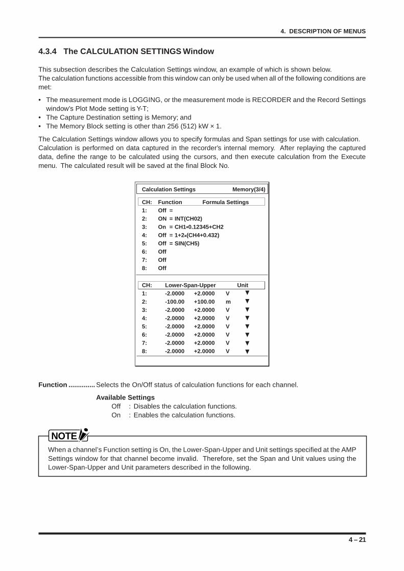
4 – 21
4. DESCRIPTION OF MENUS
4.3.4 The CALCULATION SETTINGS Window
This subsection describes the Calculation Settings window, an example of which is shown below.The calculation functions accessible from this window can only be used when all of the following conditions aremet:
• The measurement mode is LOGGING, or the measurement mode is RECORDER and the Record Settingswindow’s Plot Mode setting is Y-T;
• The Capture Destination setting is Memory; and• The Memory Block setting is other than 256 (512) kW × 1.
The Calculation Settings window allows you to specify formulas and Span settings for use with calculation.Calculation is performed on data captured in the recorder’s internal memory. After replaying the captureddata, define the range to be calculated using the cursors, and then execute calculation from the Executemenu. The calculated result will be saved at the final Block No.
Calculation Settings Memory(3/4)
CH: Function Formula Settings1: Off =2: ON = INT(CH02)3: On = CH1*0.12345+CH24: Off = 1+2*(CH4+0.432)5: Off = SIN(CH5)6: Off7: Off8: Off
CH: Lower-Span-Upper Unit1: -2.0000 +2.0000 V2: -100.00 +100.00 m3: -2.0000 +2.0000 V4: -2.0000 +2.0000 V5: -2.0000 +2.0000 V6: -2.0000 +2.0000 V7: -2.0000 +2.0000 V8: -2.0000 +2.0000 V
Function .............. Selects the On/Off status of calculation functions for each channel.
Available SettingsOff : Disables the calculation functions.On : Enables the calculation functions.
NOTEWhen a channel’s Function setting is On, the Lower-Span-Upper and Unit settings specified at the AMPSettings window for that channel become invalid. Therefore, set the Span and Unit values using theLower-Span-Upper and Unit parameters described in the following.

4 – 22
4. DESCRIPTION OF MENUS
FORMULA SETTINGS ... This parameter can only be set for a channel for which the Function setting is On. Itspecifies a numerical formula containing up to 32 terms.
Available Functions
Symbol Definition Symbol Definition
+ Addition SQRT Square root
- Subtraction INT Integration
* Multiplication DINT Double integration
/ Division SIN Sine
MEAN Moving mean COS Cosine
LOG Logarithm TAN Tangent
EXP Exponential mean ASIN Arc sine
ABS Absolute value ACOS Arc cosine
DIF Differentiation ATAN Arc tangent
DDIF Double differentiation PI pi (π)
MEAN (Moving Mean)
Because the MEAN function permits averaging of data corresponding to a specifiednumber of points, noise can be eliminated from data containing interference. Thenumber of points to be averaged can be set from 1 to 128.
DIF (Differentiation) and DDIF (Double Differentiation)
Differentiation and double differentiation operations use Lagrange’s five-order inter-polation formula.With a five-order interpolation formula, the data of one point is obtained from thevalues of five points before or after that point. Calculation is performed, however, forthe first point by using its five subsequent points and for the final point by using itsfive preceding points.
INT (Integration) and DINT (Double Integration)
Integration and double integration operations use a trapezoidal formula.With a trapezoidal formula, the average of the target point and its previous point ismultiplied by “Delta t” to obtain the area, after which all the data preceding the targetpoint are added.
SIN (Sine) and COS (Cosine)
The result of a SIN or COS operation is displayed within the range of -1 and +1. Theangle is calculated in the counter-clockwise direction for positive values or the clock-wise direction for negative values.
ASIN (Arc Sine), ACOS (Arc Cosine), and ATAN (Arc Tangent)
If the absolute value of the target data of an ASIN or ACOS operation is 1 or more,any value equal to +1 or higher is processed as +1 and any value equal to -1 orlower is processed as -1. For ASIN, ACOS, and ATAN operations, the calculatedresult is displayed as an angle (RAD) ranging from -π/2 to +π/2.
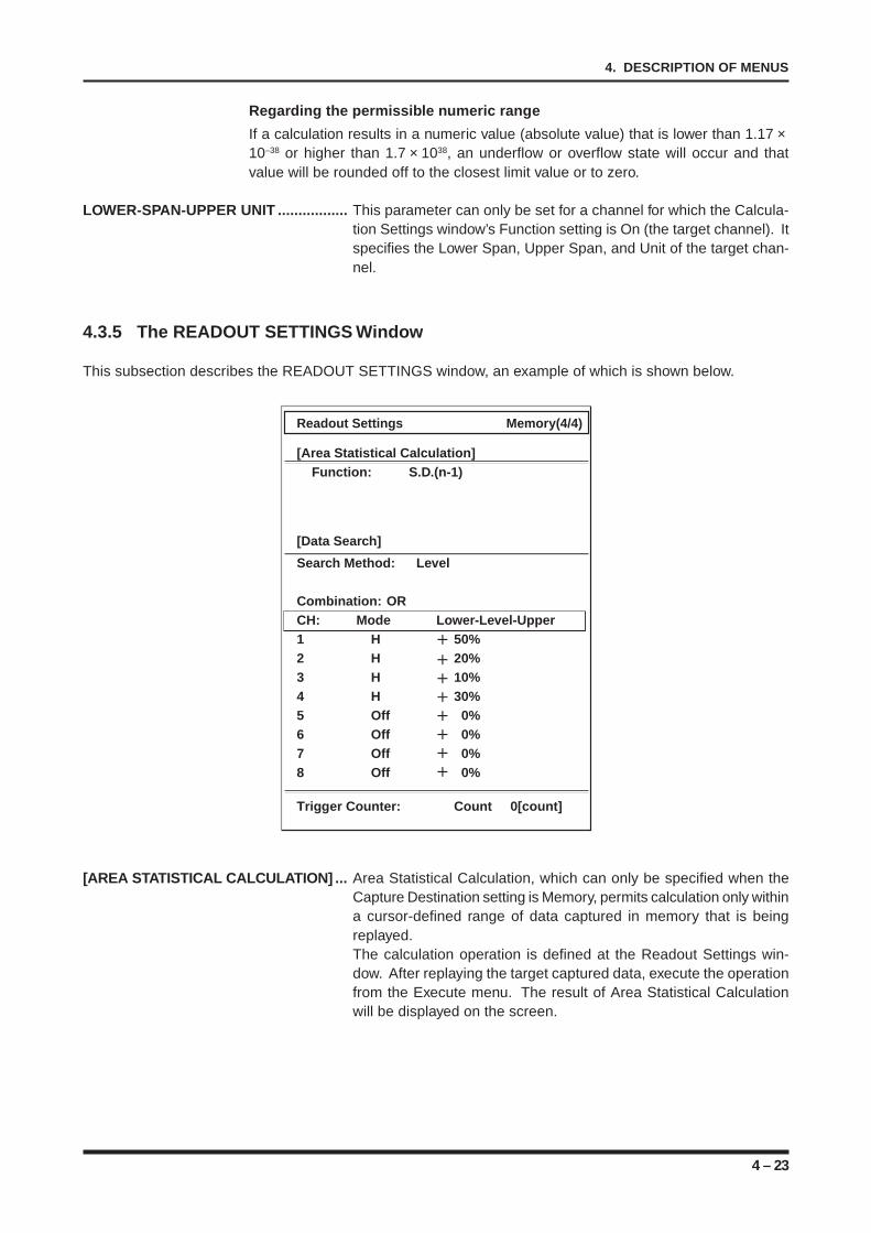
4 – 23
4. DESCRIPTION OF MENUS
Regarding the permissible numeric range
If a calculation results in a numeric value (absolute value) that is lower than 1.17 ×10–38 or higher than 1.7 × 1038, an underflow or overflow state will occur and thatvalue will be rounded off to the closest limit value or to zero.
LOWER-SPAN-UPPER UNIT ................. This parameter can only be set for a channel for which the Calcula-tion Settings window’s Function setting is On (the target channel). Itspecifies the Lower Span, Upper Span, and Unit of the target chan-nel.
4.3.5 The READOUT SETTINGS Window
This subsection describes the READOUT SETTINGS window, an example of which is shown below.
Readout Settings Memory(4/4)
[Area Statistical Calculation]Function: S.D.(n-1)
[Data Search]
Search Method: Level
Combination: ORCH: Mode Lower-Level-Upper1 H 50%2 H 20%3 H 10%4 H 30%5 Off 0%6 Off 0%7 Off 0%8 Off 0%
Trigger Counter: Count 0[count]
[AREA STATISTICAL CALCULATION] ... Area Statistical Calculation, which can only be specified when theCapture Destination setting is Memory, permits calculation only withina cursor-defined range of data captured in memory that is beingreplayed.The calculation operation is defined at the Readout Settings win-dow. After replaying the target captured data, execute the operationfrom the Execute menu. The result of Area Statistical Calculationwill be displayed on the screen.
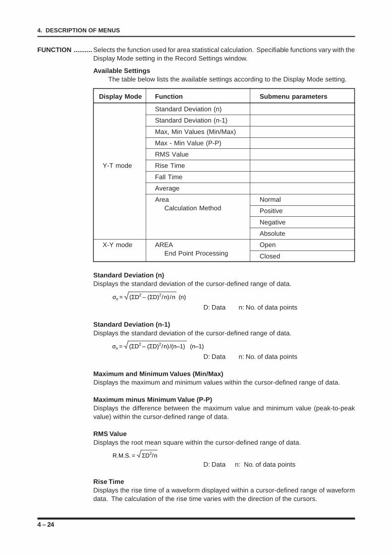
4 – 24
4. DESCRIPTION OF MENUS
FUNCTION .......... Selects the function used for area statistical calculation. Specifiable functions vary with theDisplay Mode setting in the Record Settings window.
Available SettingsThe table below lists the available settings according to the Display Mode setting.
Display Mode Function Submenu parameters
Standard Deviation (n)
Standard Deviation (n-1)
Max, Min Values (Min/Max)
Max - Min Value (P-P)
RMS Value
Y-T mode Rise Time
Fall Time
Average
Area NormalCalculation Method Positive
Negative
Absolute
X-Y mode AREA OpenEnd Point Processing Closed
Standard Deviation (n)Displays the standard deviation of the cursor-defined range of data.
σn = (ΣD2 – (ΣD)2/n)/n (n)
D: Data n: No. of data points
Standard Deviation (n-1)Displays the standard deviation of the cursor-defined range of data.
σn = (ΣD2 – (ΣD)2/n)/(n–1) (n–1)
D: Data n: No. of data points
Maximum and Minimum Values (Min/Max)Displays the maximum and minimum values within the cursor-defined range of data.
Maximum minus Minimum Value (P-P)Displays the difference between the maximum value and minimum value (peak-to-peakvalue) within the cursor-defined range of data.
RMS ValueDisplays the root mean square within the cursor-defined range of data.
R.M.S. = ΣD2/n
D: Data n: No. of data points
Rise TimeDisplays the rise time of a waveform displayed within a cursor-defined range of waveformdata. The calculation of the rise time varies with the direction of the cursors.
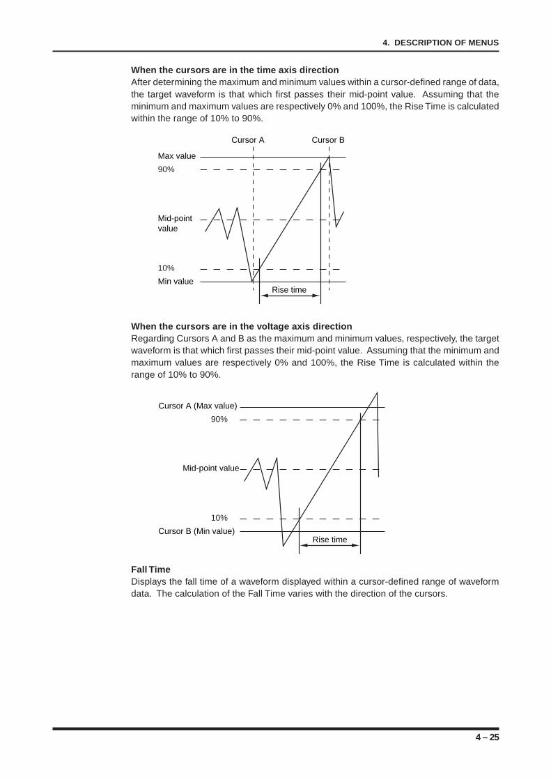
4 – 25
4. DESCRIPTION OF MENUS
When the cursors are in the time axis directionAfter determining the maximum and minimum values within a cursor-defined range of data,the target waveform is that which first passes their mid-point value. Assuming that theminimum and maximum values are respectively 0% and 100%, the Rise Time is calculatedwithin the range of 10% to 90%.
When the cursors are in the voltage axis directionRegarding Cursors A and B as the maximum and minimum values, respectively, the targetwaveform is that which first passes their mid-point value. Assuming that the minimum andmaximum values are respectively 0% and 100%, the Rise Time is calculated within therange of 10% to 90%.
Fall TimeDisplays the fall time of a waveform displayed within a cursor-defined range of waveformdata. The calculation of the Fall Time varies with the direction of the cursors.
Cursor A (Max value)
90%
Mid-point value
10%
Cursor B (Min value)Rise time
Max value
90%
Mid-point value
10%
Min value
Cursor A Cursor B
Rise time
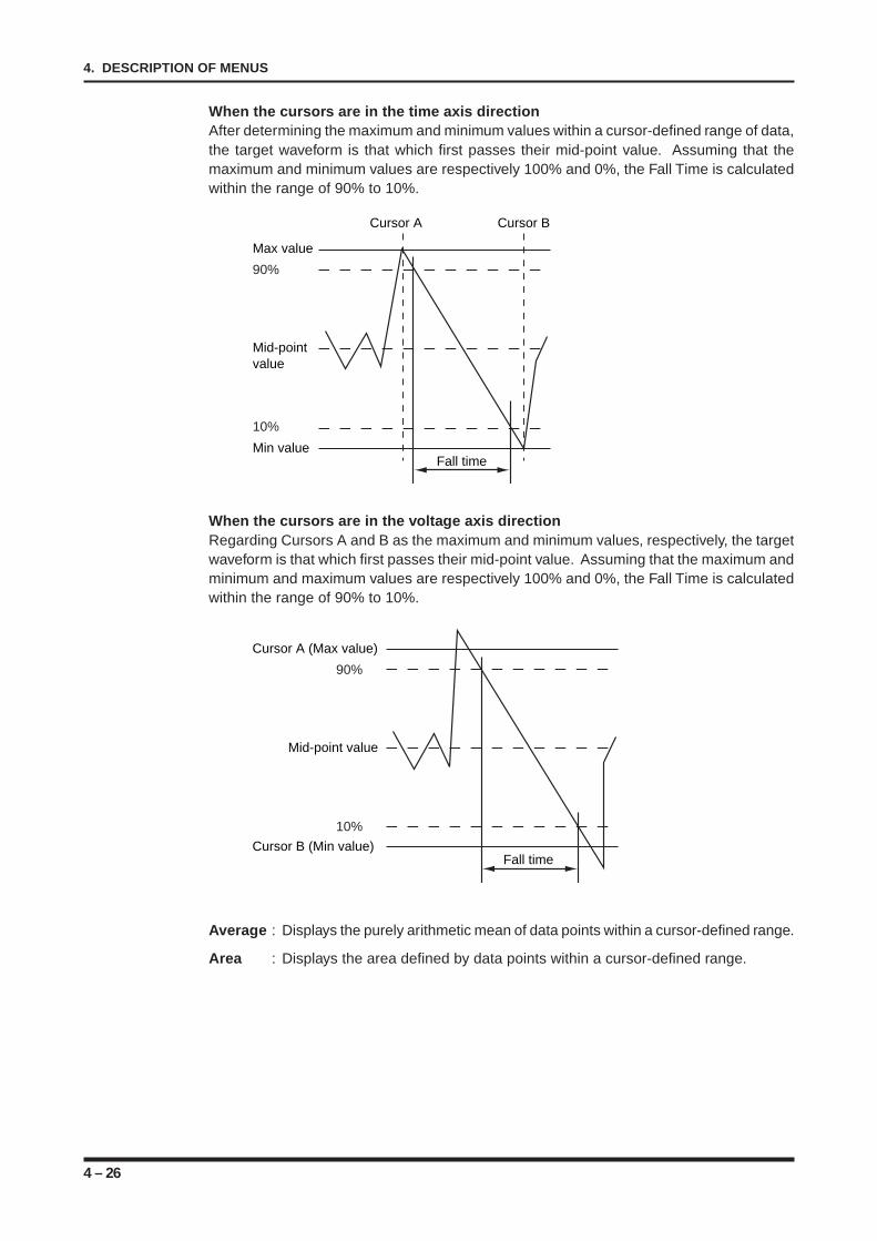
4 – 26
4. DESCRIPTION OF MENUS
When the cursors are in the time axis directionAfter determining the maximum and minimum values within a cursor-defined range of data,the target waveform is that which first passes their mid-point value. Assuming that themaximum and minimum values are respectively 100% and 0%, the Fall Time is calculatedwithin the range of 90% to 10%.
When the cursors are in the voltage axis directionRegarding Cursors A and B as the maximum and minimum values, respectively, the targetwaveform is that which first passes their mid-point value. Assuming that the maximum andminimum and maximum values are respectively 100% and 0%, the Fall Time is calculatedwithin the range of 90% to 10%.
Average : Displays the purely arithmetic mean of data points within a cursor-defined range.
Area : Displays the area defined by data points within a cursor-defined range.
Max value
90%
Mid-point value
10%
Min value
Cursor A Cursor B
Fall time
Cursor A (Max value)
90%
Mid-point value
10%
Cursor B (Min value)Fall time
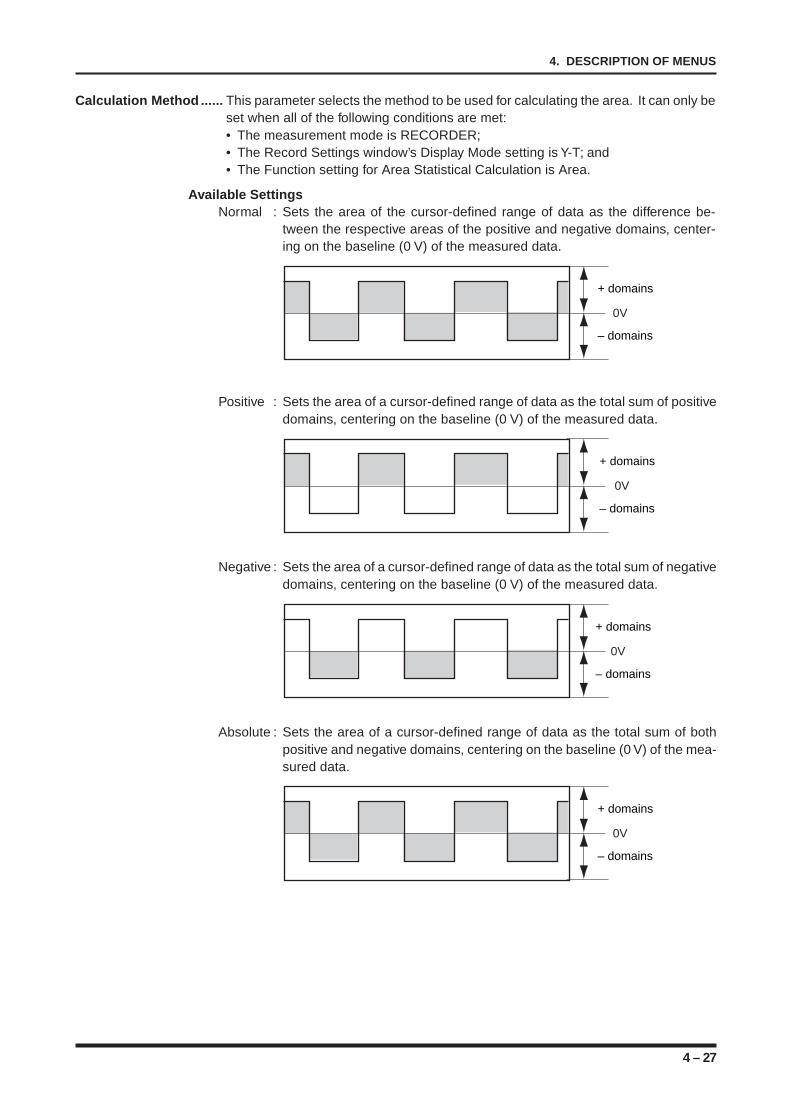
4 – 27
4. DESCRIPTION OF MENUS
Calculation Method ...... This parameter selects the method to be used for calculating the area. It can only beset when all of the following conditions are met:• The measurement mode is RECORDER;• The Record Settings window’s Display Mode setting is Y-T; and• The Function setting for Area Statistical Calculation is Area.
Available SettingsNormal : Sets the area of the cursor-defined range of data as the difference be-
tween the respective areas of the positive and negative domains, center-ing on the baseline (0 V) of the measured data.
+ domains
– domains
0V
Positive : Sets the area of a cursor-defined range of data as the total sum of positivedomains, centering on the baseline (0 V) of the measured data.
+ domains
– domains
0V
Negative : Sets the area of a cursor-defined range of data as the total sum of negativedomains, centering on the baseline (0 V) of the measured data.
+ domains
– domains
0V
Absolute : Sets the area of a cursor-defined range of data as the total sum of bothpositive and negative domains, centering on the baseline (0 V) of the mea-sured data.
+ domains
– domains
0V
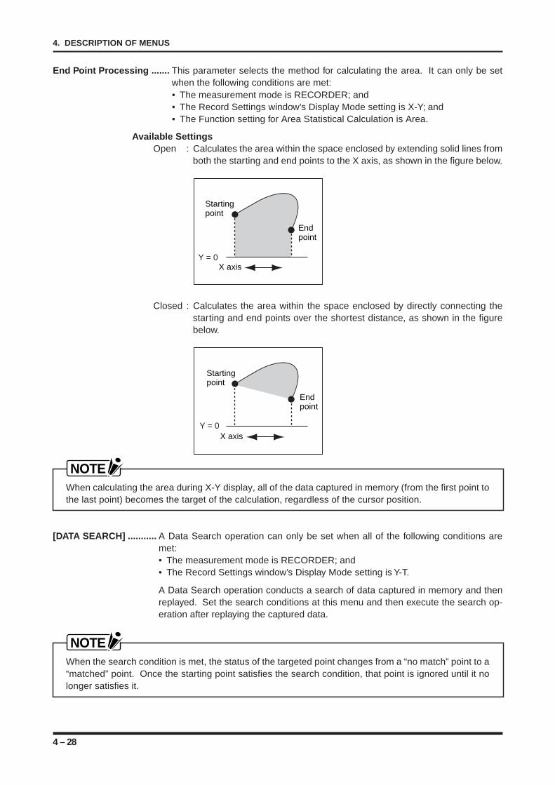
4 – 28
4. DESCRIPTION OF MENUS
End Point Processing ....... This parameter selects the method for calculating the area. It can only be setwhen the following conditions are met:• The measurement mode is RECORDER; and• The Record Settings window’s Display Mode setting is X-Y; and• The Function setting for Area Statistical Calculation is Area.
Available SettingsOpen : Calculates the area within the space enclosed by extending solid lines from
both the starting and end points to the X axis, as shown in the figure below.
Starting point
Endpoint
Y = 0X axis
Closed : Calculates the area within the space enclosed by directly connecting thestarting and end points over the shortest distance, as shown in the figurebelow.
Starting point
Endpoint
Y = 0X axis
NOTEWhen calculating the area during X-Y display, all of the data captured in memory (from the first point tothe last point) becomes the target of the calculation, regardless of the cursor position.
[DATA SEARCH] ........... A Data Search operation can only be set when all of the following conditions aremet:• The measurement mode is RECORDER; and• The Record Settings window’s Display Mode setting is Y-T.
A Data Search operation conducts a search of data captured in memory and thenreplayed. Set the search conditions at this menu and then execute the search op-eration after replaying the captured data.
NOTEWhen the search condition is met, the status of the targeted point changes from a “no match” point to a“matched” point. Once the starting point satisfies the search condition, that point is ignored until it nolonger satisfies it.
4 – 29
4. DESCRIPTION OF MENUS
SEARCH METHOD ....... This parameter’s setting is fixed to Level, which lets you search for a data positionthat satisfies the specified Level condition. A submenu for setting the Level condi-tion appears below this parameter.
COMBINATION ............. Selects the method for satisfying the Level condition.
Available SettingsOR : Searches for the position where a single channel among the target chan-
nels satisfies the search condition (which has not yet been met any otherchannel).
AND : Searches for the position where all of the target channels satisfy the searchcondition.
MODE ............................ Selects the Level condition.
Available SettingsOff : Set this condition for any channel that is to be excluded from the Data
Search operation.H : The Level condition is satisfied when an input waveform exceeds the speci-
fied Level value.L : The Level condition is satisfied when an input waveform falls below the
specified Level value.Win In : Sets the Lower-limit and Upper-limit levels for each channel. The Level
condition is met when a captured waveform goes inside both the specifiedLower-limit and Upper-limit levels.
Win Out : Sets the Lower-limit and Upper-limit levels for each channel. The Levelcondition is met when a captured waveform goes outside both the speci-fied Lower-limit and Upper-limit levels.
LOWER-LEVEL UPPER ..... Sets the search levels for captured data. Set the level in a range of -100% to+100% in 1% steps.If the Mode setting is Win In or Win Out, be sure to set the difference between theLower and Upper Levels to 5% or more. (The Lower limit of the specifiable rangeis -100% and its Upper limit is +100%).Example: For a 5 V range: -5V = -100%, +5V = +100%
TRIGGER COUNTER ......... This function determines how many times or how long to ignore the targetedpoint(s) from the time the Level condition is first satisfied until the condition se-lected by the Trigger Counter parameter is satisfied.Count : Searches for the position which has satisfied the Level condition for the
specified number of times.
Available Settings1 to 255 [count]
Filter : Searches for the position which has satisfied the Level condition for atleast the specified time interval. The actual time is the product of thisFilter setting and the Sample Interval setting.
Available Settings1 to 255
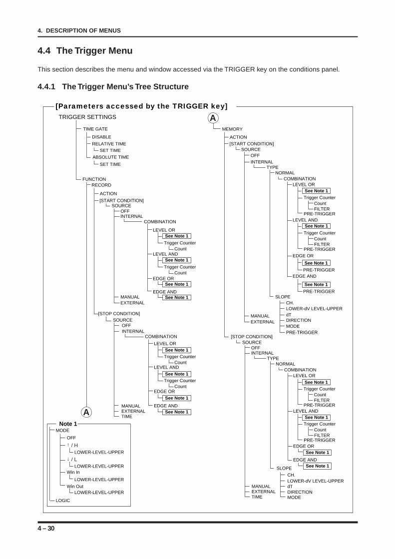
4 – 30
4. DESCRIPTION OF MENUS
4.4 The Trigger Menu
This section describes the menu and window accessed via the TRIGGER key on the conditions panel.
4.4.1 The Trigger Menu’s Tree Structure
TRIGGER SETTINGS
[Parameters accessed by the TRIGGER key]
MEMORY
SOURCEOFFINTERNAL
MANUALEXTERNAL
TYPE
COMBINATION
[START CONDITION]
PRE-TRIGGER
PRE-TRIGGER
LEVEL OR
LEVEL AND
EDGE OR
[STOP CONDITION]
NORMAL
EDGE AND
SLOPECH.LOWER-dV LEVEL-UPPERdTDIRECTIONMODEPRE-TRIGGER
MANUAL
TIME
SLOPE
CH.
dTLOWER-dV LEVEL-UPPER
DIRECTION
SOURCEOFFINTERNAL
TYPE
COMBINATION
EXTERNAL
MANUAL
TIMEEXTERNAL
LEVEL OR
LEVEL AND
EDGE OR
NORMAL
EDGE AND
MODE
TIME GATE
SET TIME
SET TIME
ABSOLUTE TIME
RECORDFUNCTION
ACTION
DISABLE
RELATIVE TIME
SOURCEOFFINTERNAL
MANUALEXTERNAL
COMBINATION
[START CONDITION]
LEVEL OR
LEVEL AND
SOURCEOFFINTERNAL
COMBINATION
[STOP CONDITION]
LEVEL OR
LEVEL AND
EDGE OR
CountTrigger Counter
See Note 1
See Note 1
See Note 1
See Note 1
See Note 1
See Note 1
See Note 1
See Note 1
See Note 1
CountTrigger Counter
See Note 1
CountTrigger Counter
See Note 1
CountFILTER
Trigger Counter
PRE-TRIGGER
See Note 1
CountFILTER
Trigger Counter
PRE-TRIGGER
See Note 1
CountFILTER
Trigger Counter
PRE-TRIGGER
See Note 1
CountFILTER
Trigger Counter
PRE-TRIGGER
See Note 1
CountTrigger Counter
See Note 1
EDGE AND
EDGE OR
EDGE AND
MODE
LOGIC
OFF
↑ / H
↓ / L
Win In
LOWER-LEVEL-UPPER
LOWER-LEVEL-UPPER
LOWER-LEVEL-UPPER
Win OutLOWER-LEVEL-UPPER
Note 1
A
ACTION
A
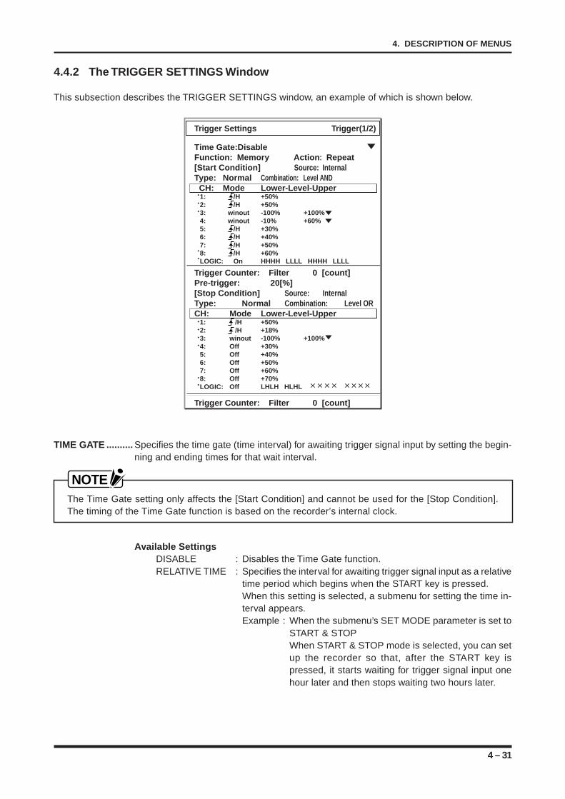
4 – 31
4. DESCRIPTION OF MENUS
4.4.2 The TRIGGER SETTINGS Window
This subsection describes the TRIGGER SETTINGS window, an example of which is shown below.
Trigger Settings Trigger(1/2)
Time Gate:DisableFunction: Memory Action: Repeat[Start Condition] Source: InternalType: Normal Combination: Level AND
CH: Mode Lower-Level-Upper 1: /H +50% 2: /H +50% 3: winout -100% +100% 4: winout -10% +60% 5: /H +30% 6: /H +40% 7: /H +50% 8: /H +60% LOGIC: On HHHH LLLL HHHH LLLL
Trigger Counter: Filter 0 [count]Pre-trigger: 20[%][Stop Condition] Source: InternalType: Normal Combination: Level ORCH: Mode Lower-Level-Upper 1: /H +50% 2: /H +18% 3: winout -100% +100% 4: Off +30% 5: Off +40% 6: Off +50% 7: Off +60% 8: Off +70% LOGIC: Off LHLH HLHL
Trigger Counter: Filter 0 [count]
TIME GATE .......... Specifies the time gate (time interval) for awaiting trigger signal input by setting the begin-ning and ending times for that wait interval.
NOTEThe Time Gate setting only affects the [Start Condition] and cannot be used for the [Stop Condition].The timing of the Time Gate function is based on the recorder’s internal clock.
Available SettingsDISABLE : Disables the Time Gate function.RELATIVE TIME : Specifies the interval for awaiting trigger signal input as a relative
time period which begins when the START key is pressed.When this setting is selected, a submenu for setting the time in-terval appears.Example : When the submenu’s SET MODE parameter is set to
START & STOPWhen START & STOP mode is selected, you can setup the recorder so that, after the START key ispressed, it starts waiting for trigger signal input onehour later and then stops waiting two hours later.
4 – 32
4. DESCRIPTION OF MENUS
ABSOLUTE TIME : Specifies the time wait interval as absolute starting and stoppingtimes.When this setting is selected, a submenu for setting the time in-terval appears.Example : When the submenu’s SET MODE parameter is set to
START & STOPWhen START & STOP mode is selected, you can setup the recorder so that its starts waiting for triggersignal input at 01:00:00 on August 10, 1999 and thenstops waiting at 17:30:00 on August 11, 1999.
SET TIME : Can only be set when the Time Gate setting is Relative Time or Absolute Time.
SET MODE : Selects the mode for setting the Time Gate parameter’s wait interval.
Available SettingsSTART TIME : Enables only the starting time. When this setting is selected, a
submenu for setting the starting time appears. The available set-tings vary with the Time Gate setting.When START & STOP mode is selected, you can set up the re-corder so that, after the START key is pressed, it starts waitingfor trigger signal input one hour later and then stops waiting twohours later.
START & STOP : Enables the starting and stopping times. When this setting isselected, one submenu each appears for setting the starting andstopping times. The available settings vary with the Time Gatesetting.
NOTEThe TIME GATE setting only affects the START CONDITION and cannot be used for the STOPCONDITION.• When the Time Gate setting is Relative Time, both the starting and ending times must be specified
relative to the starting time of measurement in the range of 0000:00:01 to 9999:59:59 (hours:minutes:seconds).
• When the Time Gate setting is Absolute Time, both the starting and ending times must be specified.The following table describes the relationship between the absolute starting and ending times.
Starting time Ending time Operation
Current time or earlier Current time or earlier The Time Gate function is disabled
Current time or earlier After current time Only the ending time is recognized.
After current time Current time or earlier Only the starting time is recognized.
After current time After current time Both the starting and ending times arerecognized, but the starting time cannotbe set later than the ending time.
4 – 33
4. DESCRIPTION OF MENUS
FUNCTION .......... Selects how the recorder will operate after the trigger condition is satisfied.
Available SettingsRECORD : After triggering, the recorder starts displaying the measured data on the
screen or recording it onto chart paper.MEMORY : After triggering, the recorder starts capturing data to a disk either in an
internal memory device (a hard disk drive*1 or MO drive*2) or in an exter-nal memory device connected via the SCSI interface unit*3.*1 Only if the 3.5” hard disk drive is installed.*2 Only if the MO drive is installed.*3 Only if the SCSI interface unit is installed.
NOTEWhen the Function setting is Memory, the destination of data capture conforms to the memory deviceselected by the Capture Destination setting in the Memory Settings window.
ACTION ............... This parameter selects whether the specified operation will be triggered only once or re-peatedly.
Available SettingsSINGLE : The specified operation is triggered once and then the trigger is disarmed.REPEAT: Until the STOP key is pressed, the specified operation is repeatedly per-
formed whenever its trigger condition is satisfied.
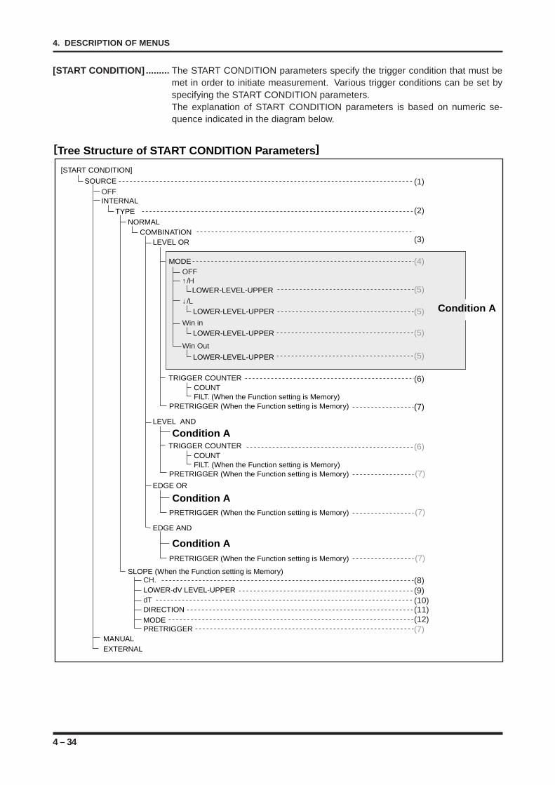
4 – 34
4. DESCRIPTION OF MENUS
[START CONDITION] ......... The START CONDITION parameters specify the trigger condition that must bemet in order to initiate measurement. Various trigger conditions can be set byspecifying the START CONDITION parameters.The explanation of START CONDITION parameters is based on numeric se-quence indicated in the diagram below.
[Tree Structure of START CONDITION Parameters]
TYPEINTERNAL
COMBINATIONLEVEL OR
TRIGGER COUNTERCOUNTFILT. (When the Function setting is Memory)
PRETRIGGER (When the Function setting is Memory)
LEVEL AND
EDGE OR
OFFSOURCE
[START CONDITION]
NORMAL
EDGE AND
SLOPE (When the Function setting is Memory)CH.LOWER-dV LEVEL-UPPERdTDIRECTION
MODEPRETRIGGER
MANUALEXTERNAL
MODEOFF↑/H
LOWER-LEVEL-UPPER
↓/LLOWER-LEVEL-UPPER
Win inLOWER-LEVEL-UPPER
Win Out
LOWER-LEVEL-UPPER
(2)
(1)
(3)
(6)
(6)
(7)
(7)
(4)
(5)
(5)
(5)
(5)
(8)(9)(10)(11)(12)(7)
Condition A
Condition A
Condition A
Condition A
TRIGGER COUNTERCOUNTFILT. (When the Function setting is Memory)
PRETRIGGER (When the Function setting is Memory)
(7)PRETRIGGER (When the Function setting is Memory)
(7)PRETRIGGER (When the Function setting is Memory)
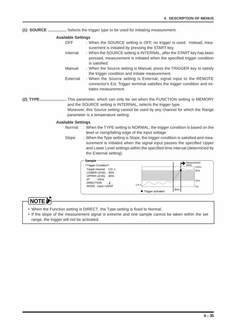
4 – 35
4. DESCRIPTION OF MENUS
(1) SOURCE ................. Selects the trigger type to be used for initiating measurement.
Available SettingsOFF : When the SOURCE setting is OFF, no trigger is used. Instead, mea-
surement is initiated by pressing the START key.Internal : When the SOURCE setting is INTERNAL, after the START key has been
pressed, measurement is initiated when the specified trigger conditionis satisfied.
Manual : When the Source setting is Manual, press the TRIGGER key to satisfythe trigger condition and initiate measurement.
External : When the Source setting is External, signal input to the REMOTEconnector’s Ext. Trigger terminal satisfies the trigger condition and ini-tiates measurement.
(2) TYPE........................ This parameter, which can only be set when the FUNCTION setting is MEMORYand the SOURCE setting is INTERNAL, selects the trigger type.Moreover, this Source setting cannot be used by any channel for which the Rangeparameter is a temperature setting.
Available SettingsNormal : When the TYPE setting is NORMAL, the trigger condition is based on the
level or rising/falling edge of the input voltage.Slope : When the Type setting is Slope, the trigger condition is satisfied and mea-
surement is initiated when the signal input passes the specified Upperand Lower Level settings within the specified time interval (determined bythe External setting).
Trigger activated
100%
30%
0%
80%
CH.1
Measurement starts
Sample <Trigger Condition>
Target channel : CH. 1 LOWER LEVEL : 30%UPPER LEVEL : 80%dT : 10msDIRECTION :MODE : Input <dV/dT
8ms
NOTE• When the Function setting is DIRECT, the Type setting is fixed to Normal.• If the slope of the measurement signal is extreme and one sample cannot be taken within the set
range, the trigger will not be activated.
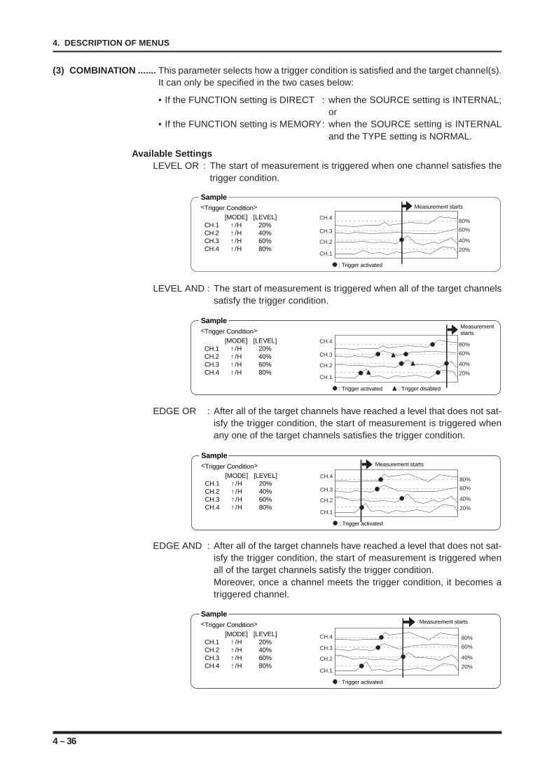
4 – 36
4. DESCRIPTION OF MENUS
(3) COMBINATION ....... This parameter selects how a trigger condition is satisfied and the target channel(s).It can only be specified in the two cases below:
• If the FUNCTION setting is DIRECT : when the SOURCE setting is INTERNAL;or
• If the FUNCTION setting is MEMORY: when the SOURCE setting is INTERNALand the TYPE setting is NORMAL.
Available SettingsLEVEL OR : The start of measurement is triggered when one channel satisfies the
trigger condition.
60%
80%
40%
20%
CH.4
CH.1
CH.2
CH.3
: Trigger activated
Measurement starts
Sample <Trigger Condition>
[MODE] [LEVEL]CH.1 ↑/H 20%CH.2 ↑/H 40%CH.3 ↑/H 60%CH.4 ↑/H 80%
LEVEL AND : The start of measurement is triggered when all of the target channelssatisfy the trigger condition.
60%
80%
40%
20%
CH.4
CH.1
CH.2
CH.3
: Trigger activated : Trigger disabled
Measurement starts
Sample <Trigger Condition>
[MODE] [LEVEL]CH.1 ↑/H 20%CH.2 ↑/H 40%CH.3 ↑/H 60%CH.4 ↑/H 80%
EDGE OR : After all of the target channels have reached a level that does not sat-isfy the trigger condition, the start of measurement is triggered whenany one of the target channels satisfies the trigger condition.
60%
80%
40%
20%
CH.4
CH.1
CH.2
CH.3
: Trigger activated
Measurement starts
Sample <Trigger Condition>
[MODE] [LEVEL]CH.1 ↑/H 20%CH.2 ↑/H 40%CH.3 ↑/H 60%CH.4 ↑/H 80%
EDGE AND : After all of the target channels have reached a level that does not sat-isfy the trigger condition, the start of measurement is triggered whenall of the target channels satisfy the trigger condition.Moreover, once a channel meets the trigger condition, it becomes atriggered channel.
60%
80%
40%
20%
CH.4
CH.1
CH.2
CH.3
: Trigger activated
Measurement startsSample <Trigger Condition>
[MODE] [LEVEL]CH.1 ↑/H 20%CH.2 ↑/H 40%CH.3 ↑/H 60%CH.4 ↑/H 80%
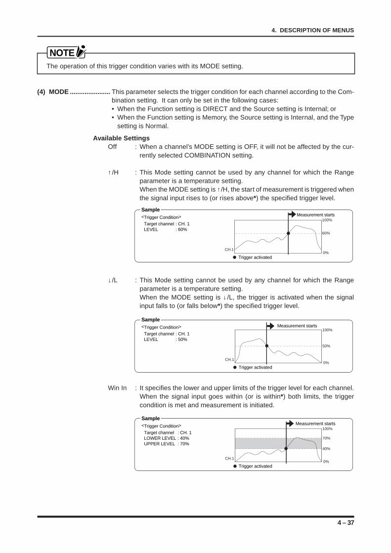
4 – 37
4. DESCRIPTION OF MENUS
NOTEThe operation of this trigger condition varies with its MODE setting.
(4) MODE ...................... This parameter selects the trigger condition for each channel according to the Com-bination setting. It can only be set in the following cases:• When the Function setting is DIRECT and the Source setting is Internal; or• When the Function setting is Memory, the Source setting is Internal, and the Type
setting is Normal.
Available SettingsOff : When a channel’s MODE setting is OFF, it will not be affected by the cur-
rently selected COMBINATION setting.
↑/H : This Mode setting cannot be used by any channel for which the Rangeparameter is a temperature setting.When the MODE setting is ↑/H, the start of measurement is triggered whenthe signal input rises to (or rises above*) the specified trigger level.
100%
60%
0%CH.1
Measurement startsSample <Trigger Condition>
Target channel : CH. 1 LEVEL : 60%
Trigger activated
↓/L : This Mode setting cannot be used by any channel for which the Rangeparameter is a temperature setting.When the MODE setting is ↓/L, the trigger is activated when the signalinput falls to (or falls below*) the specified trigger level.
50%
100%
0%CH.1
Measurement startsSample <Trigger Condition>
Target channel : CH. 1 LEVEL : 50%
Trigger activated
Win In : It specifies the lower and upper limits of the trigger level for each channel.When the signal input goes within (or is within*) both limits, the triggercondition is met and measurement is initiated.
Trigger activated
100%
70%
40%
0%CH.1
Measurement startsSample <Trigger Condition>
Target channel : CH. 1 LOWER LEVEL : 40%UPPER LEVEL : 70%
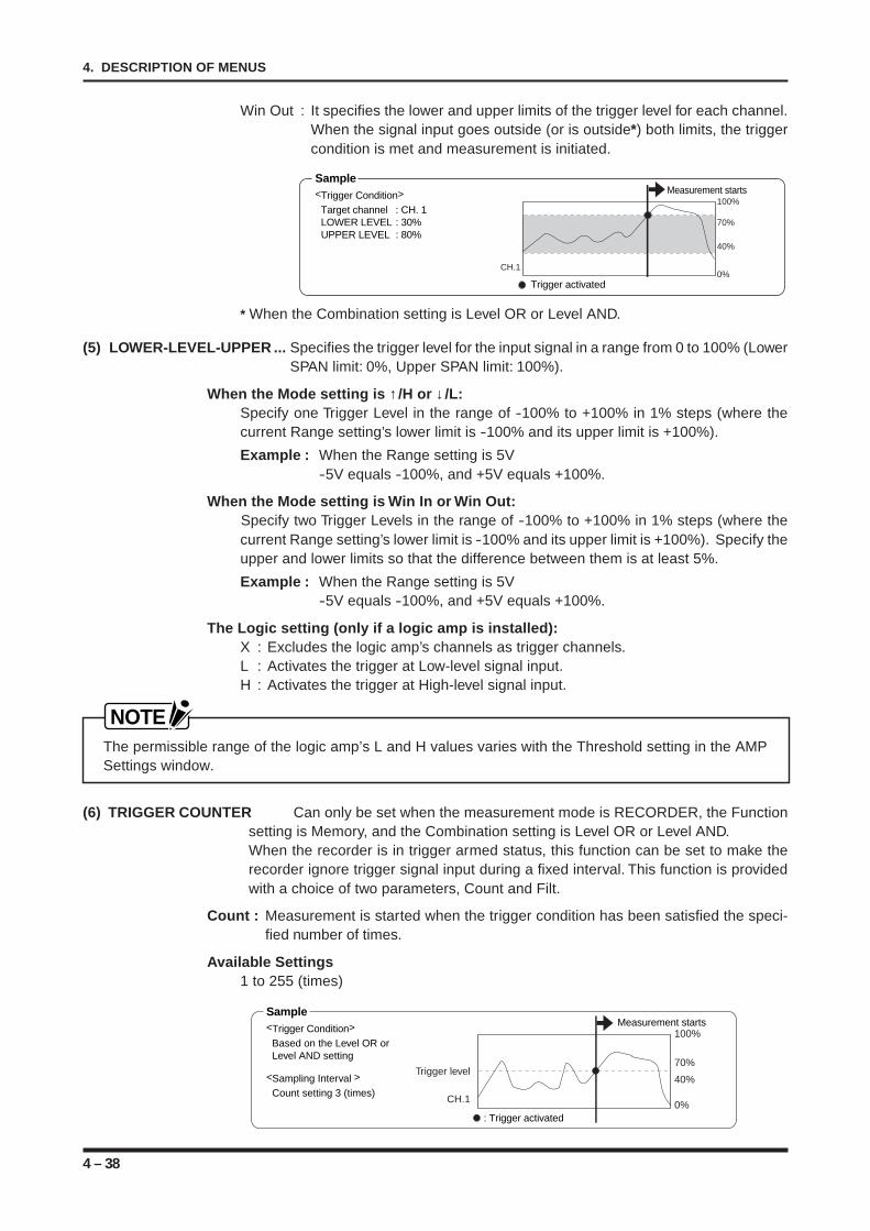
4 – 38
4. DESCRIPTION OF MENUS
Win Out : It specifies the lower and upper limits of the trigger level for each channel.When the signal input goes outside (or is outside*) both limits, the triggercondition is met and measurement is initiated.
70%
40%
100%
0%CH.1
Measurement startsSample <Trigger Condition>
Target channel : CH. 1 LOWER LEVEL : 30%UPPER LEVEL : 80%
Trigger activated
* When the Combination setting is Level OR or Level AND.
(5) LOWER-LEVEL-UPPER ... Specifies the trigger level for the input signal in a range from 0 to 100% (LowerSPAN limit: 0%, Upper SPAN limit: 100%).
When the Mode setting is ↑/H or ↓/L:Specify one Trigger Level in the range of -100% to +100% in 1% steps (where thecurrent Range setting’s lower limit is -100% and its upper limit is +100%).
Example : When the Range setting is 5V-5V equals -100%, and +5V equals +100%.
When the Mode setting is Win In or Win Out:Specify two Trigger Levels in the range of -100% to +100% in 1% steps (where thecurrent Range setting’s lower limit is -100% and its upper limit is +100%). Specify theupper and lower limits so that the difference between them is at least 5%.
Example : When the Range setting is 5V-5V equals -100%, and +5V equals +100%.
The Logic setting (only if a logic amp is installed):X : Excludes the logic amp’s channels as trigger channels.L : Activates the trigger at Low-level signal input.H : Activates the trigger at High-level signal input.
NOTEThe permissible range of the logic amp’s L and H values varies with the Threshold setting in the AMPSettings window.
(6) TRIGGER COUNTER Can only be set when the measurement mode is RECORDER, the Functionsetting is Memory, and the Combination setting is Level OR or Level AND.When the recorder is in trigger armed status, this function can be set to make therecorder ignore trigger signal input during a fixed interval. This function is providedwith a choice of two parameters, Count and Filt.
Count : Measurement is started when the trigger condition has been satisfied the speci-fied number of times.
Available Settings1 to 255 (times)
70%
100%
40%
0%CH.1
Trigger level
: Trigger activated
Measurement startsSample <Trigger Condition>
Based on the Level OR or Level AND setting
<Sampling Interval >
Count setting 3 (times)
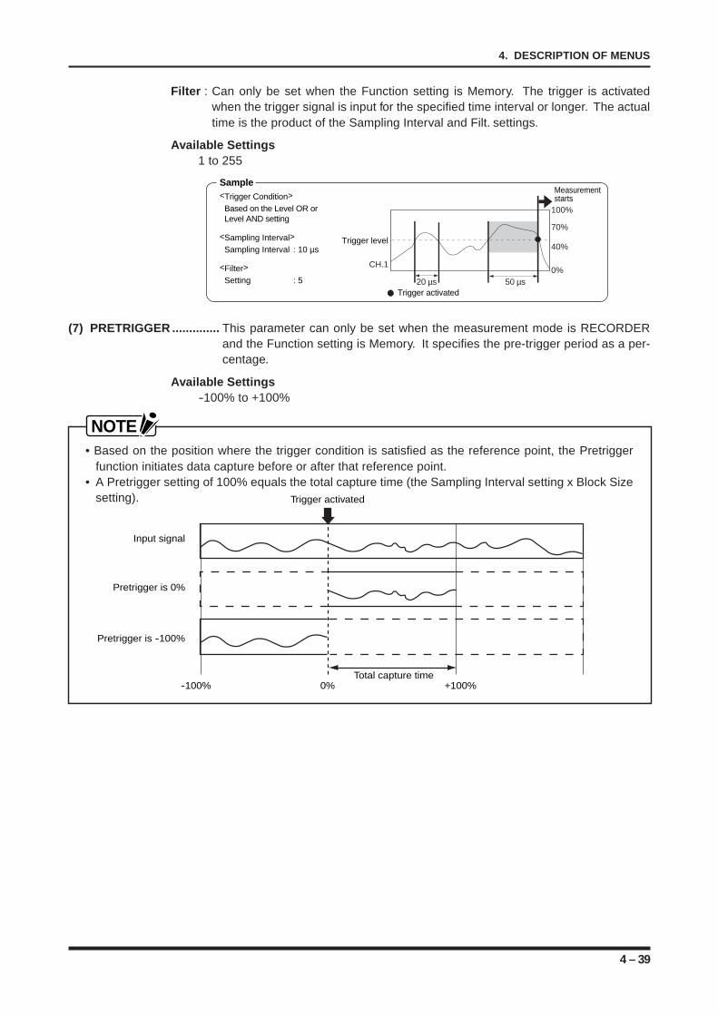
4 – 39
4. DESCRIPTION OF MENUS
Filter : Can only be set when the Function setting is Memory. The trigger is activatedwhen the trigger signal is input for the specified time interval or longer. The actualtime is the product of the Sampling Interval and Filt. settings.
Available Settings1 to 255
40%
70%
100%
0%CH.1
50 µs20 µs
Measurement starts
Sample <Trigger Condition>
Based on the Level OR or Level AND setting
<Sampling Interval>
Sampling Interval : 10 µs
<Filter> Setting : 5
Trigger activated
Trigger level
(7) PRETRIGGER .............. This parameter can only be set when the measurement mode is RECORDERand the Function setting is Memory. It specifies the pre-trigger period as a per-centage.
Available Settings-100% to +100%
NOTE• Based on the position where the trigger condition is satisfied as the reference point, the Pretrigger
function initiates data capture before or after that reference point.• A Pretrigger setting of 100% equals the total capture time (the Sampling Interval setting x Block Size
setting).
-100% +100%0%
Input signal
Pretrigger is -100%
Pretrigger is 0%
Total capture time
Trigger activated
4 – 40
4. DESCRIPTION OF MENUS
(8) CH. ................ This parameter can only be set when the measurement mode is RECORDER, the Func-tion setting is Memory, and the Type setting is Slope. It specifies one channel as the targetchannel of the slope trigger. The available channel numbers vary with the recorder’s chan-nel configuration.
(9) LOWER-dV LEVEL-UPPER ....... This parameter can only be set when the measurement mode is RE-CORDER, the Function setting is Memory, and the Type setting is Slope.It specifies the Lower and Upper limits of the slope trigger in a range of-100% to +100% in 1% steps (where the current Range setting’s lowerlimit is -100% and its upper limit is +100%). Specify the upper andlower limits so that the difference between them is at least 5%.
Example : When the Range setting is 5V-5V equals -100%, and +5V equals +100%.
(10) dT ................ This parameter can only be set when the measurement mode is RECORDER, the Func-tion setting is Memory, and the Type setting is Slope. It specifies the time during which thesignal input passes from the Lower level to the Upper level (or vice versa). The actual timeis the product of the Sampling Interval and dT settings.
Available Settings1 to 255
(11) DIRECTION .. This parameter can only be set when the measurement mode is RECORDER, the Func-tion setting is Memory, and the Type setting is Slope. It specifies the direction of the slopetrigger.
Available Settings: Selects the rise time for passing from the Lower level past the Upper level as the
slope trigger.: Selects the fall time for passing from the Upper level past the lower level as the
slope trigger.
(12) MODE ........... This parameter can only be set when the measurement mode is RECORDER, the Functionsetting is Memory, and the Type setting is Slope. It selects the mode for trigger activation.
Available SettingsSlope > dV/dT : The start of measurement is triggered when the interval for passing
from the Lower to Upper values is outside the specified time.Slope < dV/dT : The start of measurement is triggered when the interval for passing
from the Lower to Upper values is inside the specified time.
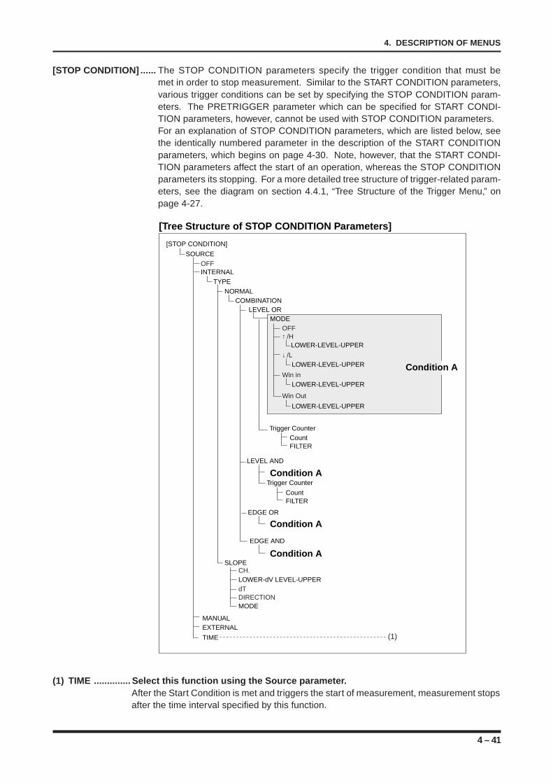
4 – 41
4. DESCRIPTION OF MENUS
[STOP CONDITION] ...... The STOP CONDITION parameters specify the trigger condition that must bemet in order to stop measurement. Similar to the START CONDITION parameters,various trigger conditions can be set by specifying the STOP CONDITION param-eters. The PRETRIGGER parameter which can be specified for START CONDI-TION parameters, however, cannot be used with STOP CONDITION parameters.For an explanation of STOP CONDITION parameters, which are listed below, seethe identically numbered parameter in the description of the START CONDITIONparameters, which begins on page 4-30. Note, however, that the START CONDI-TION parameters affect the start of an operation, whereas the STOP CONDITIONparameters its stopping. For a more detailed tree structure of trigger-related param-eters, see the diagram on section 4.4.1, “Tree Structure of the Trigger Menu,” onpage 4-27.
Condition A
[Tree Structure of STOP CONDITION Parameters]
TYPEINTERNAL
COMBINATION LEVEL OR
Trigger Counter
Trigger Counter
LEVEL AND
EDGE OR
OFFSOURCE
[STOP CONDITION]
NORMAL
EDGE AND
SLOPECH.LOWER-dV LEVEL-UPPERdTDIRECTIONMODE
MANUALEXTERNAL
MODEOFF↑ /H
LOWER-LEVEL-UPPER
↓ /LLOWER-LEVEL-UPPER
Win inLOWER-LEVEL-UPPER
Win Out
LOWER-LEVEL-UPPER
TIME
Condition A
Condition A
Condition A
CountFILTER
CountFILTER
(1)
(1) TIME .............. Select this function using the Source parameter.After the Start Condition is met and triggers the start of measurement, measurement stopsafter the time interval specified by this function.
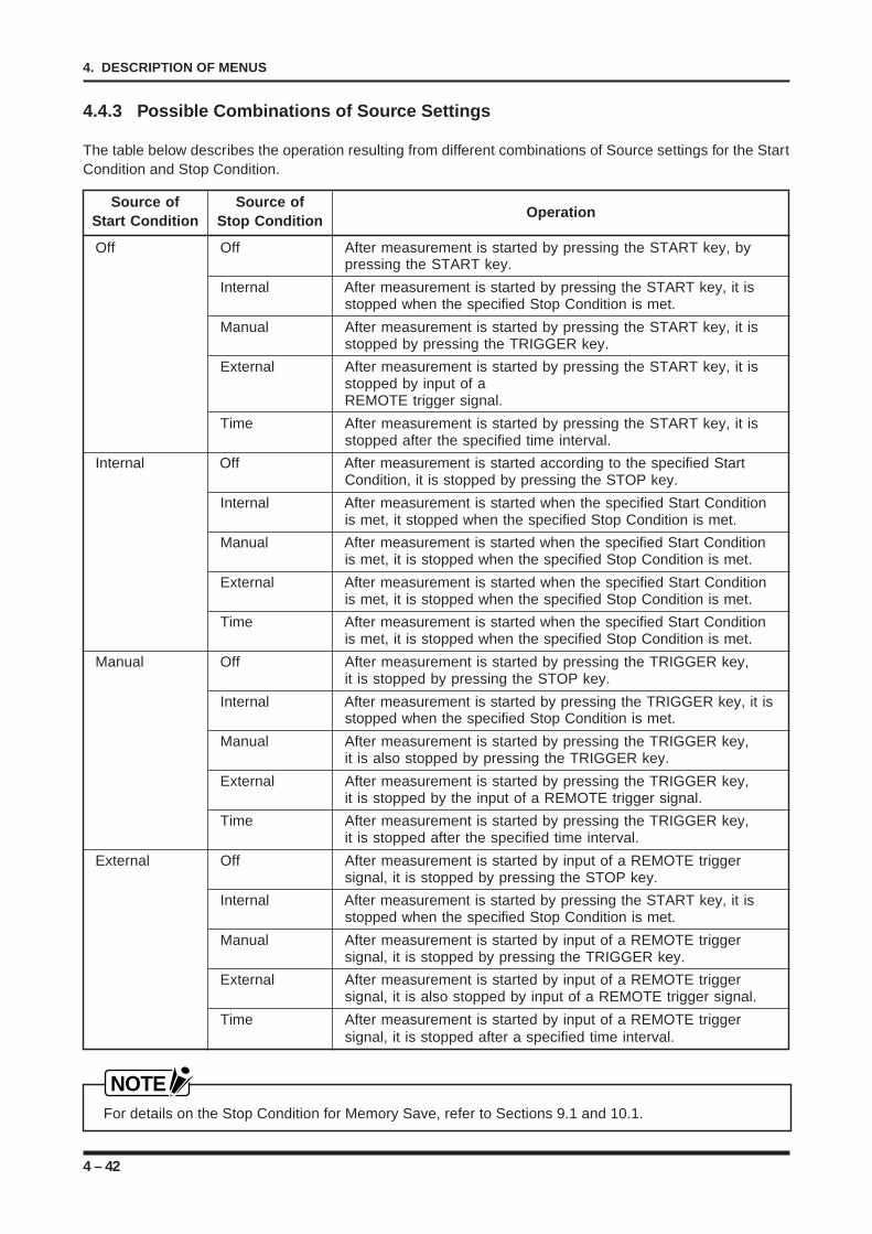
4 – 42
4. DESCRIPTION OF MENUS
4.4.3 Possible Combinations of Source Settings
The table below describes the operation resulting from different combinations of Source settings for the StartCondition and Stop Condition.
Source of Source ofOperationStart Condition Stop Condition
Off Off After measurement is started by pressing the START key, bypressing the START key.
Internal After measurement is started by pressing the START key, it isstopped when the specified Stop Condition is met.
Manual After measurement is started by pressing the START key, it isstopped by pressing the TRIGGER key.
External After measurement is started by pressing the START key, it isstopped by input of aREMOTE trigger signal.
Time After measurement is started by pressing the START key, it isstopped after the specified time interval.
Internal Off After measurement is started according to the specified StartCondition, it is stopped by pressing the STOP key.
Internal After measurement is started when the specified Start Conditionis met, it stopped when the specified Stop Condition is met.
Manual After measurement is started when the specified Start Conditionis met, it is stopped when the specified Stop Condition is met.
External After measurement is started when the specified Start Conditionis met, it is stopped when the specified Stop Condition is met.
Time After measurement is started when the specified Start Conditionis met, it is stopped when the specified Stop Condition is met.
Manual Off After measurement is started by pressing the TRIGGER key,it is stopped by pressing the STOP key.
Internal After measurement is started by pressing the TRIGGER key, it isstopped when the specified Stop Condition is met.
Manual After measurement is started by pressing the TRIGGER key,it is also stopped by pressing the TRIGGER key.
External After measurement is started by pressing the TRIGGER key,it is stopped by the input of a REMOTE trigger signal.
Time After measurement is started by pressing the TRIGGER key,it is stopped after the specified time interval.
External Off After measurement is started by input of a REMOTE triggersignal, it is stopped by pressing the STOP key.
Internal After measurement is started by pressing the START key, it isstopped when the specified Stop Condition is met.
Manual After measurement is started by input of a REMOTE triggersignal, it is stopped by pressing the TRIGGER key.
External After measurement is started by input of a REMOTE triggersignal, it is also stopped by input of a REMOTE trigger signal.
Time After measurement is started by input of a REMOTE triggersignal, it is stopped after a specified time interval.
NOTEFor details on the Stop Condition for Memory Save, refer to Sections 9.1 and 10.1.
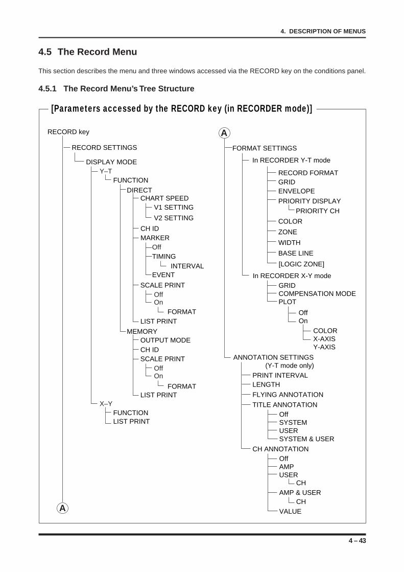
4 – 43
4. DESCRIPTION OF MENUS
4.5 The Record Menu
This section describes the menu and three windows accessed via the RECORD key on the conditions panel.
4.5.1 The Record Menu’s Tree Structure
RECORD SETTINGS
DISPLAY MODEY–T
FUNCTION
DIRECT
V1 SETTINGCHART SPEED
V2 SETTING
MARKER
TIMINGOff
EVENT INTERVAL
SCALE PRINTOffOn
FORMAT
FORMAT
LIST PRINT
CH ID
X–YFUNCTIONLIST PRINT
MEMORYOUTPUT MODE
SCALE PRINTOffOn
LIST PRINT
CH ID ANNOTATION SETTINGS
(Y-T mode only)PRINT INTERVALLENGTH
FLYING ANNOTATION
TITLE ANNOTATIONOffSYSTEMUSER
FORMAT SETTINGS
RECORD FORMATGRIDENVELOPE
PRIORITY DISPLAY
COLOR
PRIORITY CH
ZONE
BASE LINE
[LOGIC ZONE]
WIDTH
SYSTEM & USER
In RECORDER Y-T mode
In RECORDER X-Y mode
RECORD key
[Parameters accessed by the RECORD key (in RECORDER mode)]
A
A
GRIDCOMPENSATION MODEPLOT
OffOn
COLORX-AXISY-AXIS
CH ANNOTATIONOffAMPUSER
CH
CHVALUE
AMP & USER
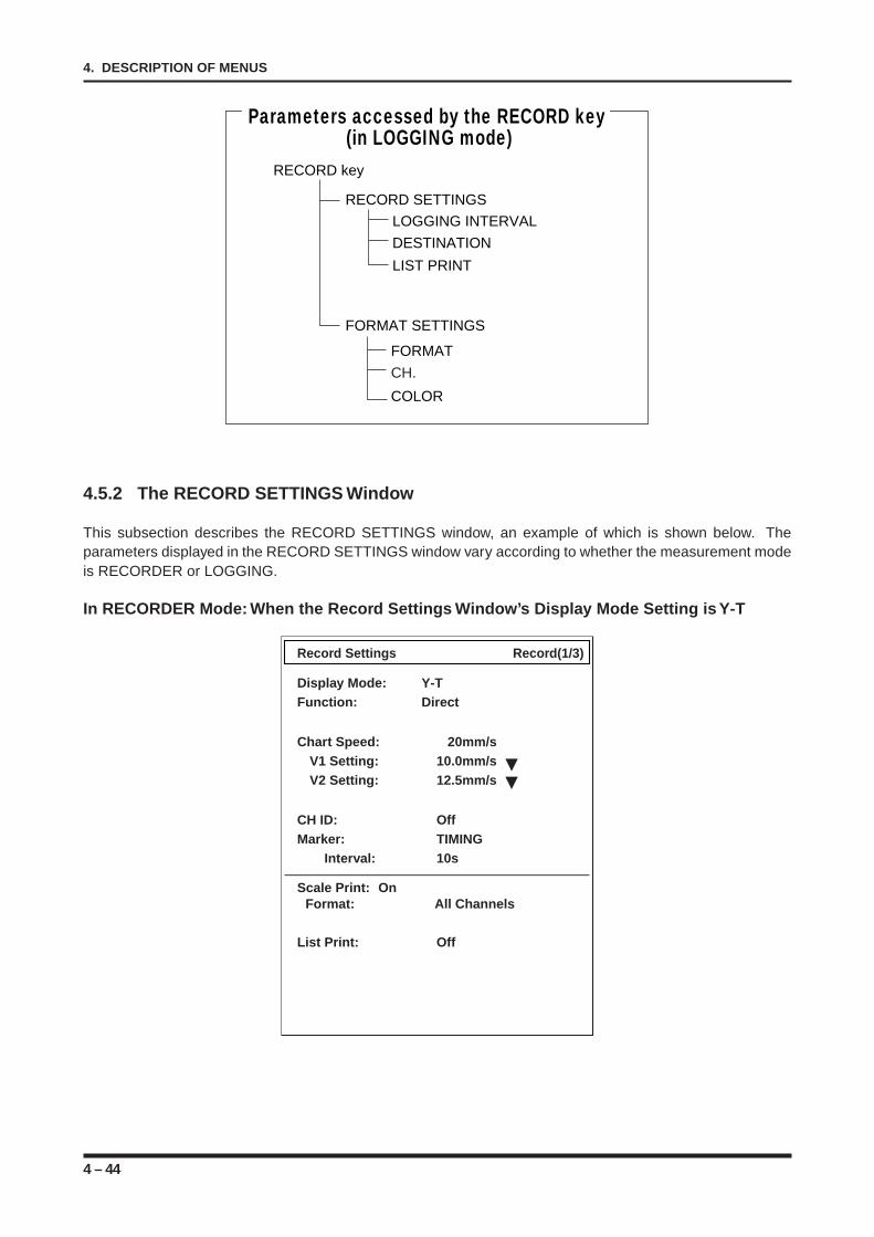
4 – 44
4. DESCRIPTION OF MENUS
FORMAT SETTINGS
FORMAT
CH.
COLOR
RECORD SETTINGS
LOGGING INTERVAL
DESTINATION
LIST PRINT
Parameters accessed by the RECORD key (in LOGGING mode)
RECORD key
4.5.2 The RECORD SETTINGS Window
This subsection describes the RECORD SETTINGS window, an example of which is shown below. Theparameters displayed in the RECORD SETTINGS window vary according to whether the measurement modeis RECORDER or LOGGING.
In RECORDER Mode: When the Record Settings Window’s Display Mode Setting is Y-T
Record Settings Record(1/3)
Display Mode: Y-TFunction: Direct
Chart Speed: 20mm/sV1 Setting: 10.0mm/sV2 Setting: 12.5mm/s
CH ID: OffMarker: TIMING
Interval: 10s
Scale Print: OnFormat: All Channels
List Print: Off
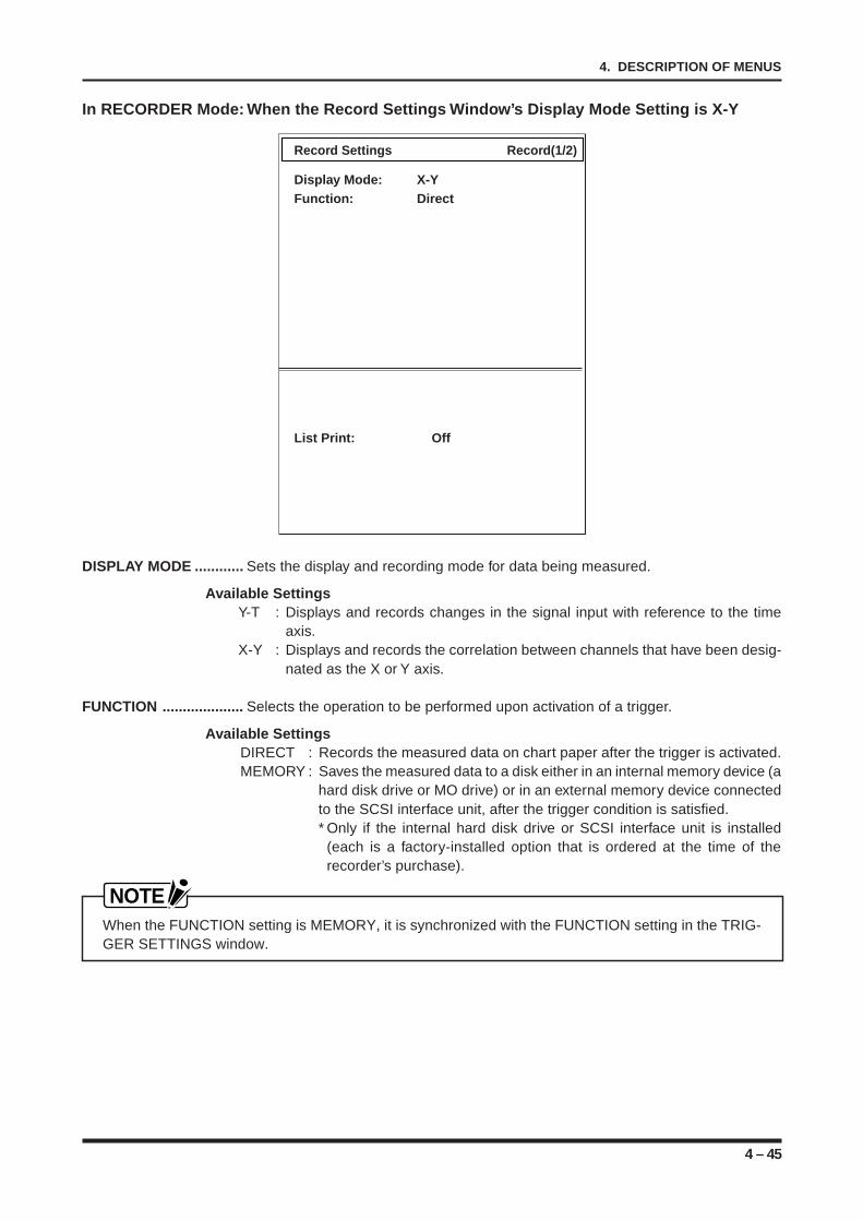
4 – 45
4. DESCRIPTION OF MENUS
In RECORDER Mode: When the Record Settings Window’s Display Mode Setting is X-Y
Record Settings Record(1/2)
Display Mode: X-YFunction: Direct
List Print: Off
DISPLAY MODE ............ Sets the display and recording mode for data being measured.
Available SettingsY-T : Displays and records changes in the signal input with reference to the time
axis.X-Y : Displays and records the correlation between channels that have been desig-
nated as the X or Y axis.
FUNCTION .................... Selects the operation to be performed upon activation of a trigger.
Available SettingsDIRECT : Records the measured data on chart paper after the trigger is activated.MEMORY : Saves the measured data to a disk either in an internal memory device (a
hard disk drive or MO drive) or in an external memory device connectedto the SCSI interface unit, after the trigger condition is satisfied.* Only if the internal hard disk drive or SCSI interface unit is installed
(each is a factory-installed option that is ordered at the time of therecorder’s purchase).
NOTEWhen the FUNCTION setting is MEMORY, it is synchronized with the FUNCTION setting in the TRIG-GER SETTINGS window.
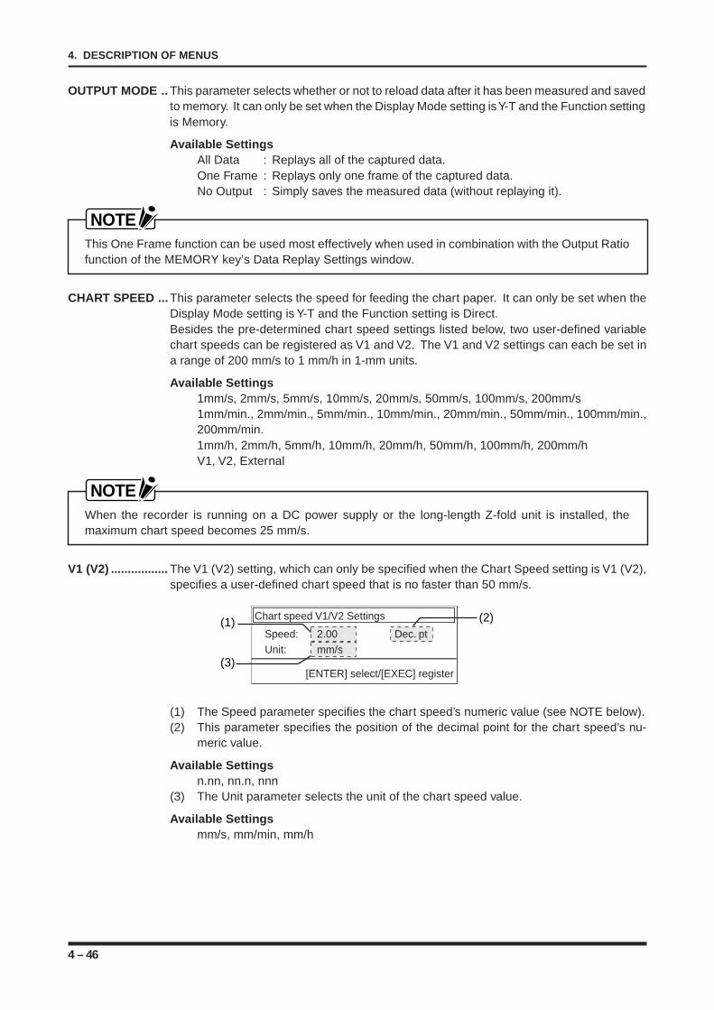
4 – 46
4. DESCRIPTION OF MENUS
OUTPUT MODE .. This parameter selects whether or not to reload data after it has been measured and savedto memory. It can only be set when the Display Mode setting is Y-T and the Function settingis Memory.
Available SettingsAll Data : Replays all of the captured data.One Frame : Replays only one frame of the captured data.No Output : Simply saves the measured data (without replaying it).
NOTEThis One Frame function can be used most effectively when used in combination with the Output Ratiofunction of the MEMORY key’s Data Replay Settings window.
CHART SPEED ... This parameter selects the speed for feeding the chart paper. It can only be set when theDisplay Mode setting is Y-T and the Function setting is Direct.Besides the pre-determined chart speed settings listed below, two user-defined variablechart speeds can be registered as V1 and V2. The V1 and V2 settings can each be set ina range of 200 mm/s to 1 mm/h in 1-mm units.
Available Settings1mm/s, 2mm/s, 5mm/s, 10mm/s, 20mm/s, 50mm/s, 100mm/s, 200mm/s1mm/min., 2mm/min., 5mm/min., 10mm/min., 20mm/min., 50mm/min., 100mm/min.,200mm/min.1mm/h, 2mm/h, 5mm/h, 10mm/h, 20mm/h, 50mm/h, 100mm/h, 200mm/hV1, V2, External
NOTEWhen the recorder is running on a DC power supply or the long-length Z-fold unit is installed, themaximum chart speed becomes 25 mm/s.
V1 (V2) ................. The V1 (V2) setting, which can only be specified when the Chart Speed setting is V1 (V2),specifies a user-defined chart speed that is no faster than 50 mm/s.
Chart speed V1/V2 Settings
Speed: 2.00 Dec. ptUnit: mm/s
[ENTER] select/[EXEC] register
(2)(1)
(3)
(1) The Speed parameter specifies the chart speed’s numeric value (see NOTE below).(2) This parameter specifies the position of the decimal point for the chart speed’s nu-
meric value.
Available Settingsn.nn, nn.n, nnn
(3) The Unit parameter selects the unit of the chart speed value.
Available Settingsmm/s, mm/min, mm/h
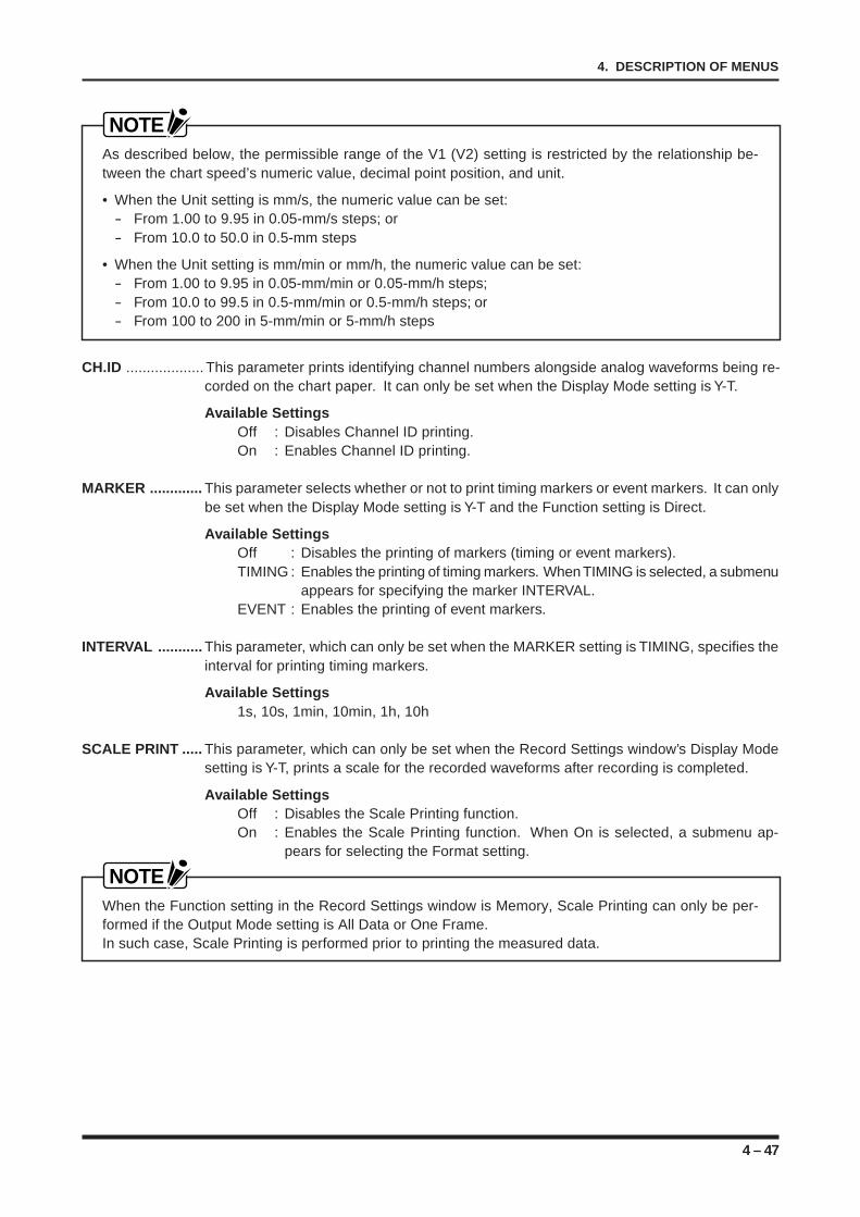
4 – 47
4. DESCRIPTION OF MENUS
NOTEAs described below, the permissible range of the V1 (V2) setting is restricted by the relationship be-tween the chart speed’s numeric value, decimal point position, and unit.
• When the Unit setting is mm/s, the numeric value can be set:- From 1.00 to 9.95 in 0.05-mm/s steps; or- From 10.0 to 50.0 in 0.5-mm steps
• When the Unit setting is mm/min or mm/h, the numeric value can be set:- From 1.00 to 9.95 in 0.05-mm/min or 0.05-mm/h steps;- From 10.0 to 99.5 in 0.5-mm/min or 0.5-mm/h steps; or- From 100 to 200 in 5-mm/min or 5-mm/h steps
CH.ID ................... This parameter prints identifying channel numbers alongside analog waveforms being re-corded on the chart paper. It can only be set when the Display Mode setting is Y-T.
Available SettingsOff : Disables Channel ID printing.On : Enables Channel ID printing.
MARKER ............. This parameter selects whether or not to print timing markers or event markers. It can onlybe set when the Display Mode setting is Y-T and the Function setting is Direct.
Available SettingsOff : Disables the printing of markers (timing or event markers).TIMING : Enables the printing of timing markers. When TIMING is selected, a submenu
appears for specifying the marker INTERVAL.EVENT : Enables the printing of event markers.
INTERVAL ........... This parameter, which can only be set when the MARKER setting is TIMING, specifies theinterval for printing timing markers.
Available Settings1s, 10s, 1min, 10min, 1h, 10h
SCALE PRINT ..... This parameter, which can only be set when the Record Settings window’s Display Modesetting is Y-T, prints a scale for the recorded waveforms after recording is completed.
Available SettingsOff : Disables the Scale Printing function.On : Enables the Scale Printing function. When On is selected, a submenu ap-
pears for selecting the Format setting.
NOTEWhen the Function setting in the Record Settings window is Memory, Scale Printing can only be per-formed if the Output Mode setting is All Data or One Frame.In such case, Scale Printing is performed prior to printing the measured data.
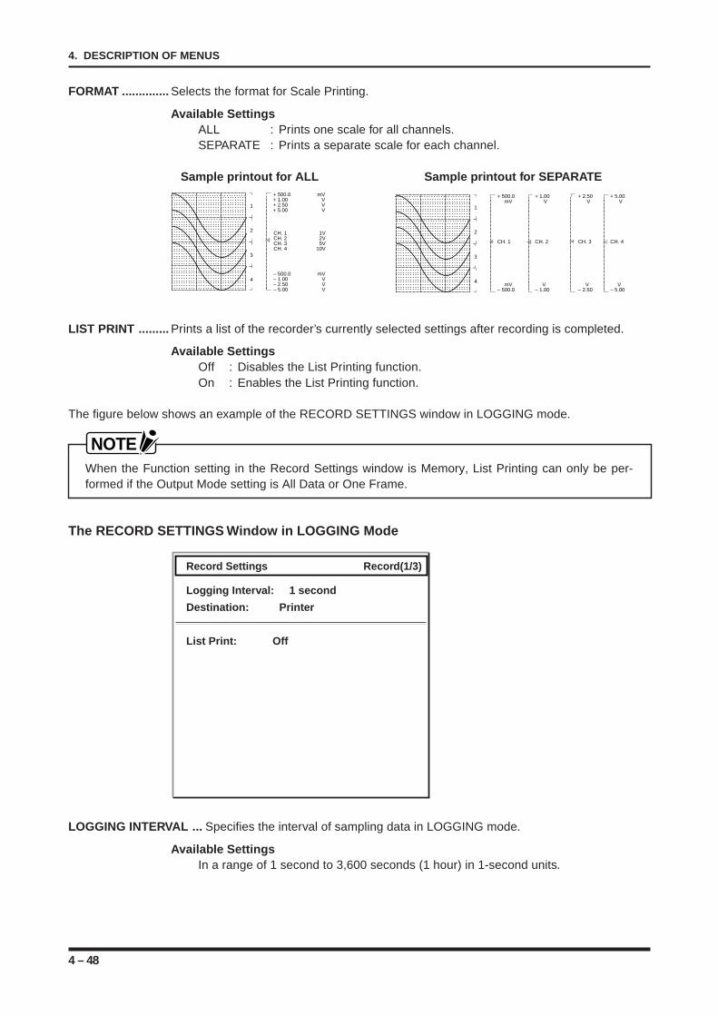
4 – 48
4. DESCRIPTION OF MENUS
FORMAT .............. Selects the format for Scale Printing.
Available SettingsALL : Prints one scale for all channels.SEPARATE : Prints a separate scale for each channel.
Sample printout for ALL Sample printout for SEPARATE+ 500.0 mV+ 1.00 V+ 2.50 V+ 5.00 V
– 500.0 mV– 1.00 V– 2.50 V– 5.00 V
CH. 1 1VCH. 2 2VCH. 3 5VCH. 4 10V
1
2
3
4
+ 500.0 mV
mV– 500.0
CH. 1
+ 1.00 V
V– 1.00
CH. 2
+ 2.50 V
V– 2.50
CH. 3
+ 5.00 V
V– 5.00
CH. 4
1
2
3
4
LIST PRINT ......... Prints a list of the recorder’s currently selected settings after recording is completed.
Available SettingsOff : Disables the List Printing function.On : Enables the List Printing function.
The figure below shows an example of the RECORD SETTINGS window in LOGGING mode.
NOTEWhen the Function setting in the Record Settings window is Memory, List Printing can only be per-formed if the Output Mode setting is All Data or One Frame.
The RECORD SETTINGS Window in LOGGING Mode
Record Settings Record(1/3)
Logging Interval: 1 second
Destination: Printer
List Print: Off
LOGGING INTERVAL ... Specifies the interval of sampling data in LOGGING mode.
Available SettingsIn a range of 1 second to 3,600 seconds (1 hour) in 1-second units.
4 – 49
4. DESCRIPTION OF MENUS
DESTINATION ..... Selects the output destination of the measured data.
Available SettingsPRINTER : Displays the measured data on the screen or plots it onto chart paper.INTERFACE : Outputs the measured data as ASCII data via the interface selected
by the Remote I/F setting in the SYSTEM key’s Option Settings win-dow.
NOTEIt is not possible to simultaneously plot the measured data onto chart paper and output it via the inter-face.
LIST PRINT ......... List Printing can only be performed if the DESTINATION setting is PRINTER. Prints a listof the recorder’s currently selected settings after recording is completed.
Available SettingsOff : Disables the List Printing function.On : Enables the List Printing function.
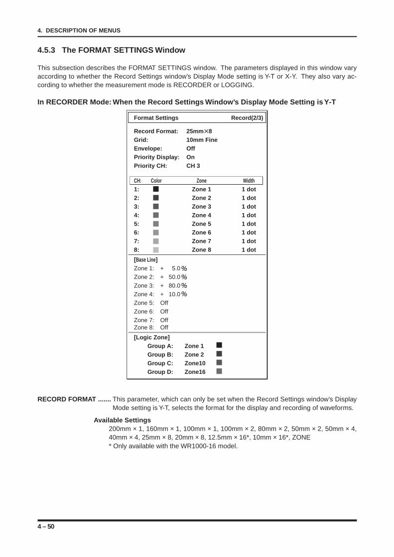
4 – 50
4. DESCRIPTION OF MENUS
4.5.3 The FORMAT SETTINGS Window
This subsection describes the FORMAT SETTINGS window. The parameters displayed in this window varyaccording to whether the Record Settings window’s Display Mode setting is Y-T or X-Y. They also vary ac-cording to whether the measurement mode is RECORDER or LOGGING.
In RECORDER Mode: When the Record Settings Window’s Display Mode Setting is Y-T
Format Settings Record(2/3)
Record Format: 25mm 8Grid: 10mm FineEnvelope: OffPriority Display: OnPriority CH: CH 3
CH: Color Zone Width1: Zone 1 1 dot2: Zone 2 1 dot3: Zone 3 1 dot4: Zone 4 1 dot5: Zone 5 1 dot6: Zone 6 1 dot7: Zone 7 1 dot8: Zone 8 1 dot
[Base Line]Zone 1: + 5.0
Zone 2: + 50.0
Zone 3: + 80.0
Zone 4: + 10.0
Zone 5: Off
Zone 6: Off
Zone 7: OffZone 8: Off
[Logic Zone]Group A: Zone 1Group B: Zone 2Group C: Zone10Group D: Zone16
RECORD FORMAT ....... This parameter, which can only be set when the Record Settings window’s DisplayMode setting is Y-T, selects the format for the display and recording of waveforms.
Available Settings200mm × 1, 160mm × 1, 100mm × 1, 100mm × 2, 80mm × 2, 50mm × 2, 50mm × 4,40mm × 4, 25mm × 8, 20mm × 8, 12.5mm × 16*, 10mm × 16*, ZONE* Only available with the WR1000-16 model.
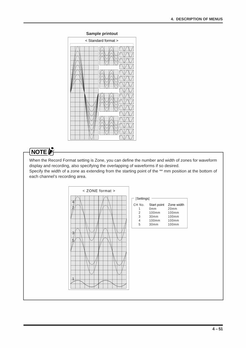
4 – 51
4. DESCRIPTION OF MENUS
Sample printout
< Standard format >
NOTEWhen the Record Format setting is Zone, you can define the number and width of zones for waveformdisplay and recording, also specifying the overlapping of waveforms if so desired.Specify the width of a zone as extending from the starting point of the ** mm position at the bottom ofeach channel’s recording area.
< ZONE format >
1
3
4
2
5
[Settings]
CH No. Start point Zone width1 0mm 20mm2 100mm 100mm3 30mm 100mm4 100mm 100mm5 30mm 100mm
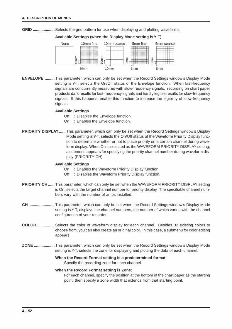
4 – 52
4. DESCRIPTION OF MENUS
GRID .................... Selects the grid pattern for use when displaying and plotting waveforms.
Available Settings (when the Display Mode setting is Y-T)
10mm
10m
m
10m
m
5mm
5mm
10mm fineNone
10mm
10mm coarse
5mm
5mm fine
5mm
5mm coarse
ENVELOPE ......... This parameter, which can only be set when the Record Settings window’s Display Modesetting is Y-T, selects the On/Off status of the Envelope function. When fast-frequencysignals are concurrently measured with slow-frequency signals, recording on chart paperproducts dark results for fast-frequency signals and hardly legible results for slow-frequencysignals. If this happens, enable this function to increase the legibility of slow-frequencysignals.
Available SettingsOff : Disables the Envelope function.On : Enables the Envelope function.
PRIORITY DISPLAY ...... This parameter, which can only be set when the Record Settings window’s DisplayMode setting is Y-T, selects the On/Off status of the Waveform Priority Display func-tion to determine whether or not to place priority on a certain channel during wave-form display. When On is selected as the WAVEFORM PRIORITY DISPLAY setting,a submenu appears for specifying the priority channel number during waveform dis-play (PRIORITY CH).
Available SettingsOn : Enables the Waveform Priority Display function.Off : Disables the Waveform Priority Display function.
PRIORITY CH ...... This parameter, which can only be set when the WAVEFORM PRIORITY DISPLAY settingis On, selects the target channel number for priority display. The specifiable channel num-bers vary with the number of amps installed.
CH ........................ This parameter, which can only be set when the Record Settings window’s Display Modesetting is Y-T, displays the channel numbers, the number of which varies with the channelconfiguration of your recorder.
COLOR ................ Selects the color of waveform display for each channel. Besides 32 existing colors tochoose from, you can also create an original color. In this case, a submenu for color editingappears.
ZONE ................... This parameter, which can only be set when the Record Settings window’s Display Modesetting is Y-T, selects the zone for displaying and plotting the data of each channel.
When the Record Format setting is a predetermined format:Specify the recording zone for each channel.
When the Record Format setting is Zone:For each channel, specify the position at the bottom of the chart paper as the startingpoint, then specify a zone width that extends from that starting point.
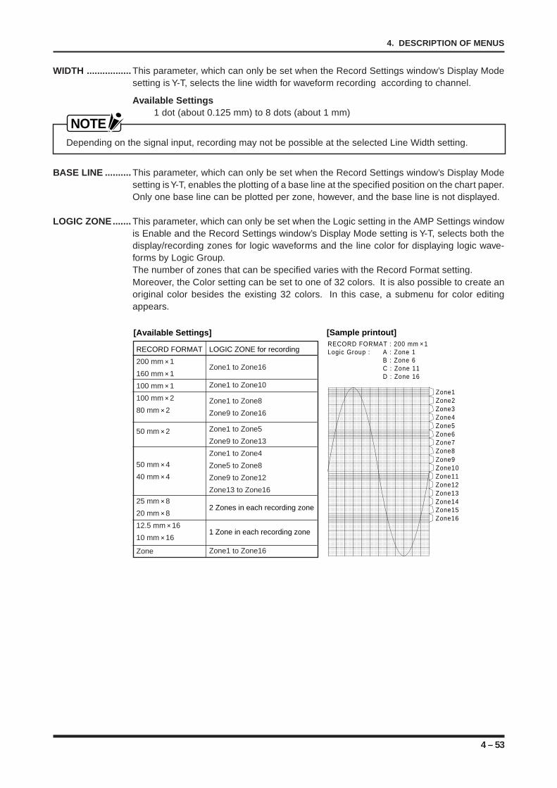
4 – 53
4. DESCRIPTION OF MENUS
WIDTH ................. This parameter, which can only be set when the Record Settings window’s Display Modesetting is Y-T, selects the line width for waveform recording according to channel.
Available Settings1 dot (about 0.125 mm) to 8 dots (about 1 mm)
NOTEDepending on the signal input, recording may not be possible at the selected Line Width setting.
BASE LINE .......... This parameter, which can only be set when the Record Settings window’s Display Modesetting is Y-T, enables the plotting of a base line at the specified position on the chart paper.Only one base line can be plotted per zone, however, and the base line is not displayed.
LOGIC ZONE....... This parameter, which can only be set when the Logic setting in the AMP Settings windowis Enable and the Record Settings window’s Display Mode setting is Y-T, selects both thedisplay/recording zones for logic waveforms and the line color for displaying logic wave-forms by Logic Group.The number of zones that can be specified varies with the Record Format setting.Moreover, the Color setting can be set to one of 32 colors. It is also possible to create anoriginal color besides the existing 32 colors. In this case, a submenu for color editingappears.
RECORD FORMAT : 200 mm × 1Logic Group : A : Zone 1
B : Zone 6C : Zone 11D : Zone 16
RECORD FORMAT
200 mm × 1
160 mm × 1
100 mm × 1
100 mm × 2
80 mm × 2
50 mm × 2
50 mm × 4
40 mm × 4
25 mm × 8
20 mm × 8
12.5 mm × 16
10 mm × 16
Zone
LOGIC ZONE for recording
Zone1 to Zone16
Zone1 to Zone10
Zone1 to Zone8
Zone9 to Zone16
Zone1 to Zone5
Zone9 to Zone13
Zone1 to Zone4
Zone5 to Zone8
Zone9 to Zone12
Zone13 to Zone16
2 Zones in each recording zone
1 Zone in each recording zone
Zone1 to Zone16
[Available Settings] [Sample printout]
Zone1Zone2Zone3Zone4Zone5Zone6Zone7Zone8Zone9Zone10Zone11Zone12Zone13Zone14Zone15Zone16
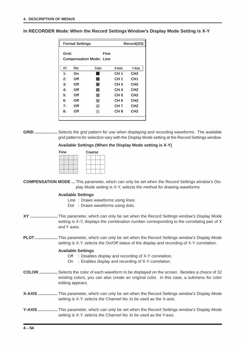
4 – 54
4. DESCRIPTION OF MENUS
In RECORDER Mode: When the Record Settings Window’s Display Mode Setting is X-Y
Format Settings Record(2/2)
Grid: FineCompensation Mode: Line
XY: Plot Color X-Axis Y-Axis1: On CH 1 CH22: Off CH 1 CH13: Off CH 3 CH24: Off CH 4 CH25: Off CH 5 CH26: Off CH 6 CH27: Off CH 7 CH28: Off CH 8 CH2
GRID .................... Selects the grid pattern for use when displaying and recording waveforms. The availablegrid patterns for selection vary with the Display Mode setting at the Record Settings window.
Available Settings (When the Display Mode setting is X-Y)
Fine Coarse
COMPENSATION MODE ... This parameter, which can only be set when the Record Settings window’s Dis-play Mode setting is X-Y, selects the method for drawing waveforms.
Available SettingsLine : Draws waveforms using lines.Dot : Draws waveforms using dots.
XY ........................ This parameter, which can only be set when the Record Settings window’s Display Modesetting is X-Y, displays the combination number corresponding to the correlating pair of Xand Y axes.
PLOT.................... This parameter, which can only be set when the Record Settings window’s Display Modesetting is X-Y, selects the On/Off status of the display and recording of X-Y correlation.
Available SettingsOff : Disables display and recording of X-Y correlation.On : Enables display and recording of X-Y correlation.
COLOR ................ Selects the color of each waveform to be displayed on the screen. Besides a choice of 32existing colors, you can also create an original color. In this case, a submenu for colorediting appears.
X-AXIS ................. This parameter, which can only be set when the Record Settings window’s Display Modesetting is X-Y, selects the Channel No. to be used as the X-axis.
Y-AXIS ................. This parameter, which can only be set when the Record Settings window’s Display Modesetting is X-Y, selects the Channel No. to be used as the Y-axis.
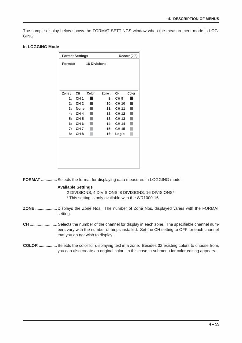
4 – 55
4. DESCRIPTION OF MENUS
The sample display below shows the FORMAT SETTINGS window when the measurement mode is LOG-GING.
In LOGGING Mode
Format Settings Record(2/3)
Format: 16 Divisions
Zone : CH Color Zone : CH Color1: CH 1 9: CH 92: CH 2 10: CH 103: None 11: CH 114: CH 4 12: CH 125: CH 5 13: CH 136: CH 6 14: CH 147: CH 7 15: CH 158: CH 8 16: Logic
FORMAT .............. Selects the format for displaying data measured in LOGGING mode.
Available Settings2 DIVISIONS, 4 DIVISIONS, 8 DIVISIONS, 16 DIVISIONS** This setting is only available with the WR1000-16.
ZONE ................... Displays the Zone Nos. The number of Zone Nos. displayed varies with the FORMATsetting.
CH ........................ Selects the number of the channel for display in each zone. The specifiable channel num-bers vary with the number of amps installed. Set the CH setting to OFF for each channelthat you do not wish to display.
COLOR ................ Selects the color for displaying text in a zone. Besides 32 existing colors to choose from,you can also create an original color. In this case, a submenu for color editing appears.
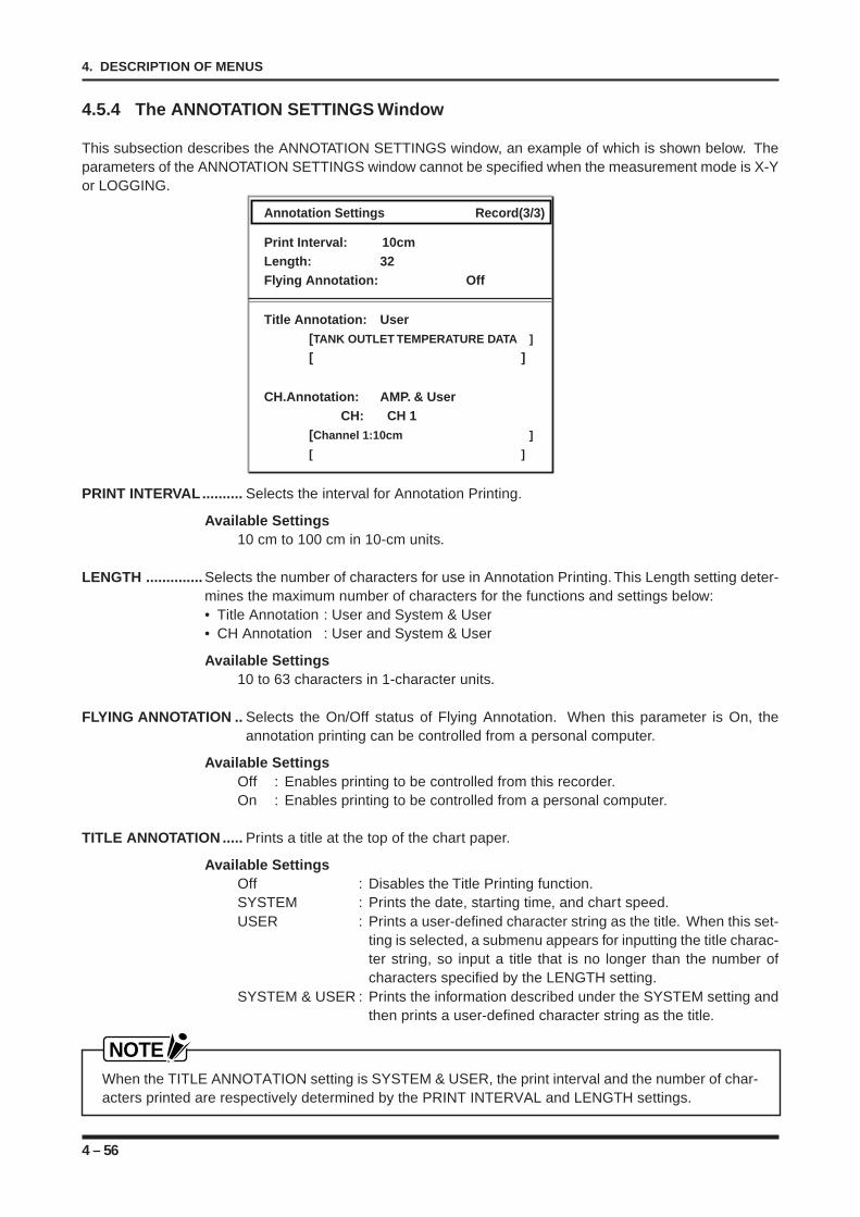
4 – 56
4. DESCRIPTION OF MENUS
4.5.4 The ANNOTATION SETTINGS Window
This subsection describes the ANNOTATION SETTINGS window, an example of which is shown below. Theparameters of the ANNOTATION SETTINGS window cannot be specified when the measurement mode is X-Yor LOGGING.
Annotation Settings Record(3/3)
Print Interval: 10cmLength: 32Flying Annotation: Off
Title Annotation: User[TANK OUTLET TEMPERATURE DATA ]
[ ]
CH.Annotation: AMP. & UserCH: CH 1
[Channel 1:10cm ]
[ ]
PRINT INTERVAL.......... Selects the interval for Annotation Printing.
Available Settings10 cm to 100 cm in 10-cm units.
LENGTH .............. Selects the number of characters for use in Annotation Printing. This Length setting deter-mines the maximum number of characters for the functions and settings below:• Title Annotation : User and System & User• CH Annotation : User and System & User
Available Settings10 to 63 characters in 1-character units.
FLYING ANNOTATION .. Selects the On/Off status of Flying Annotation. When this parameter is On, theannotation printing can be controlled from a personal computer.
Available SettingsOff : Enables printing to be controlled from this recorder.On : Enables printing to be controlled from a personal computer.
TITLE ANNOTATION ..... Prints a title at the top of the chart paper.
Available SettingsOff : Disables the Title Printing function.SYSTEM : Prints the date, starting time, and chart speed.USER : Prints a user-defined character string as the title. When this set-
ting is selected, a submenu appears for inputting the title charac-ter string, so input a title that is no longer than the number ofcharacters specified by the LENGTH setting.
SYSTEM & USER : Prints the information described under the SYSTEM setting andthen prints a user-defined character string as the title.
NOTEWhen the TITLE ANNOTATION setting is SYSTEM & USER, the print interval and the number of char-acters printed are respectively determined by the PRINT INTERVAL and LENGTH settings.
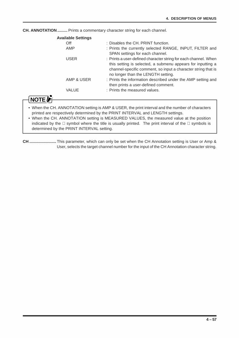
4 – 57
4. DESCRIPTION OF MENUS
CH. ANNOTATION ......... Prints a commentary character string for each channel.
Available SettingsOff : Disables the CH. PRINT function.AMP : Prints the currently selected RANGE, INPUT, FILTER and
SPAN settings for each channel.USER : Prints a user-defined character string for each channel. When
this setting is selected, a submenu appears for inputting achannel-specific comment, so input a character string that isno longer than the LENGTH setting.
AMP & USER : Prints the information described under the AMP setting andthen prints a user-defined comment.
VALUE : Prints the measured values.
NOTE• When the CH. ANNOTATION setting is AMP & USER, the print interval and the number of characters
printed are respectively determined by the PRINT INTERVAL and LENGTH settings.• When the CH. ANNOTATION setting is MEASURED VALUES, the measured value at the position
indicated by the ∇ symbol where the title is usually printed. The print interval of the ∇ symbols isdetermined by the PRINT INTERVAL setting.
CH ........................ This parameter, which can only be set when the CH Annotation setting is User or Amp &User, selects the target channel number for the input of the CH Annotation character string.
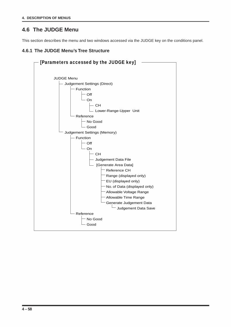
4 – 58
4. DESCRIPTION OF MENUS
4.6 The JUDGE Menu
This section describes the menu and two windows accessed via the JUDGE key on the conditions panel.
4.6.1 The JUDGE Menu’s Tree Structure
[Parameters accessed by the JUDGE key]
JUDGE Menu
Judgement Settings (Direct)
Function
Off
On
CH
Lower-Range-Upper Unit
Reference
No Good
Good
Judgement Settings (Memory)
Function
Off
On
CH
Judgement Data File
[Generate Area Data]
Reference CH
Range (displayed only)
EU (displayed only)
No. of Data (displayed only)
Allowable Voltage Range
Allowable Time Range
Generate Judgement Data
Judgement Data Save
Reference
No Good
Good
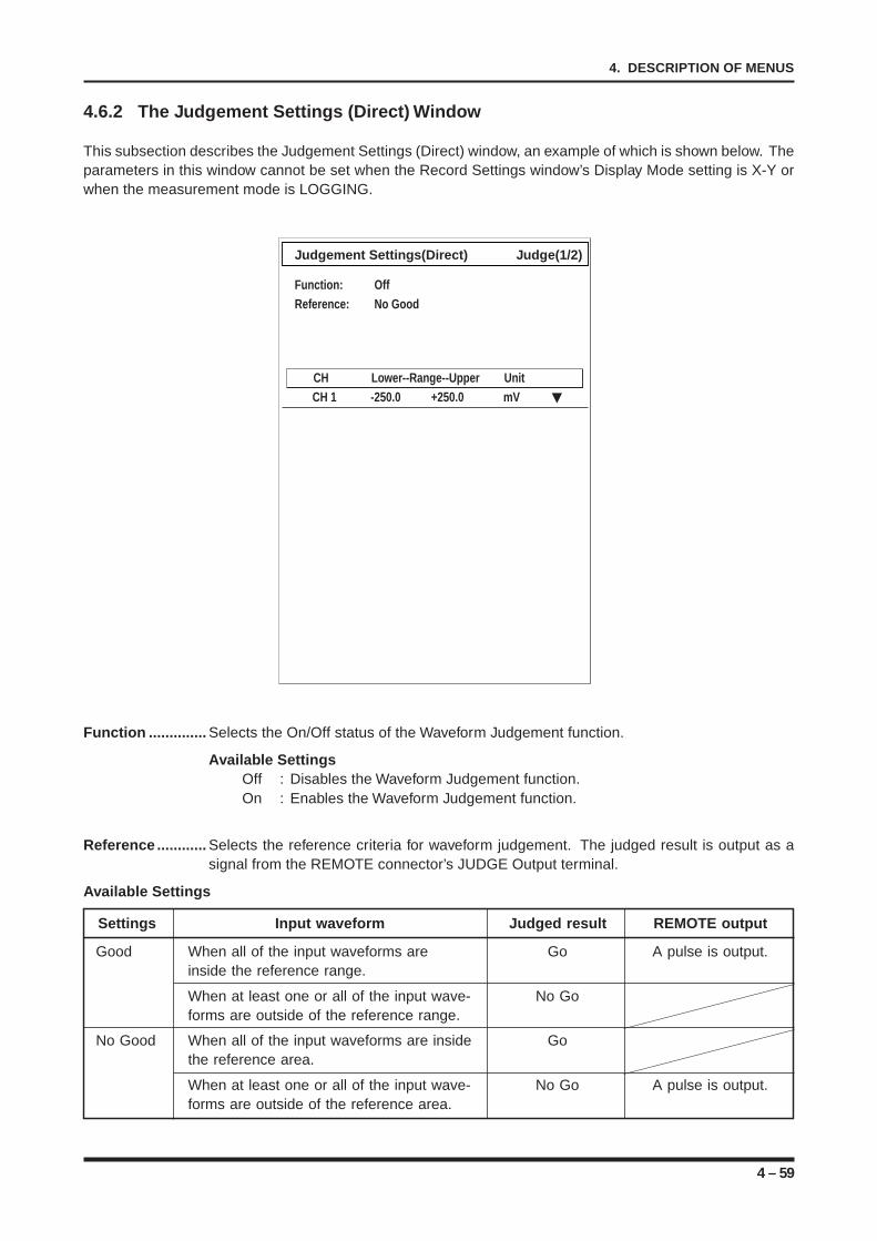
4 – 59
4. DESCRIPTION OF MENUS
Judgement Settings(Direct) Judge(1/2)
Function: OffReference: No Good
CH Lower--Range--Upper UnitCH 1 -250.0 +250.0 mV
4.6.2 The Judgement Settings (Direct) Window
This subsection describes the Judgement Settings (Direct) window, an example of which is shown below. Theparameters in this window cannot be set when the Record Settings window’s Display Mode setting is X-Y orwhen the measurement mode is LOGGING.
Function .............. Selects the On/Off status of the Waveform Judgement function.
Available SettingsOff : Disables the Waveform Judgement function.On : Enables the Waveform Judgement function.
Reference ............ Selects the reference criteria for waveform judgement. The judged result is output as asignal from the REMOTE connector’s JUDGE Output terminal.
Available Settings
Settings Input waveform Judged result REMOTE output
Good When all of the input waveforms are Go A pulse is output.inside the reference range.
When at least one or all of the input wave- No Goforms are outside of the reference range.
No Good When all of the input waveforms are inside Gothe reference area.
When at least one or all of the input wave- No Go A pulse is output.forms are outside of the reference area.
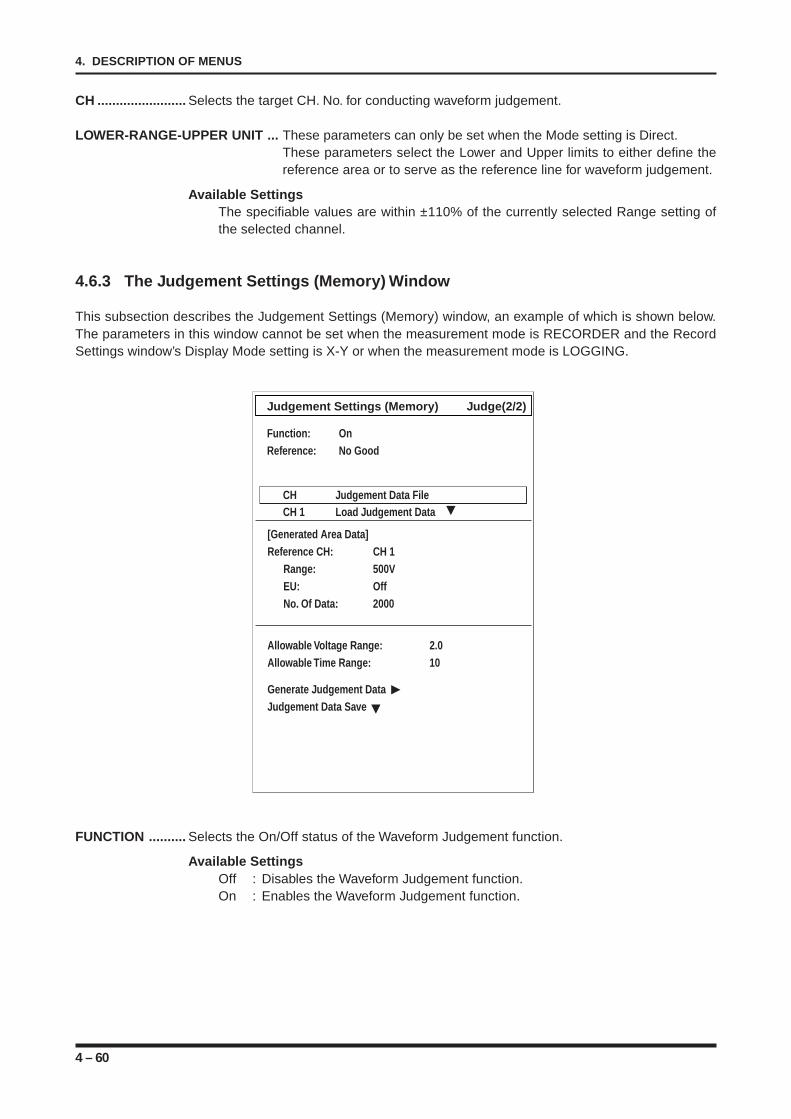
4 – 60
4. DESCRIPTION OF MENUS
CH ........................ Selects the target CH. No. for conducting waveform judgement.
LOWER-RANGE-UPPER UNIT ... These parameters can only be set when the Mode setting is Direct.These parameters select the Lower and Upper limits to either define thereference area or to serve as the reference line for waveform judgement.
Available SettingsThe specifiable values are within ±110% of the currently selected Range setting ofthe selected channel.
4.6.3 The Judgement Settings (Memory) Window
This subsection describes the Judgement Settings (Memory) window, an example of which is shown below.The parameters in this window cannot be set when the measurement mode is RECORDER and the RecordSettings window’s Display Mode setting is X-Y or when the measurement mode is LOGGING.
FUNCTION .......... Selects the On/Off status of the Waveform Judgement function.
Available SettingsOff : Disables the Waveform Judgement function.On : Enables the Waveform Judgement function.
Judgement Settings (Memory) Judge(2/2)
Function: OnReference: No Good
CH Judgement Data FileCH 1 Load Judgement Data
[Generated Area Data]Reference CH: CH 1
Range: 500VEU: OffNo. Of Data: 2000
Allowable Voltage Range: 2.0Allowable Time Range: 10
Generate Judgement DataJudgement Data Save
4 – 61
4. DESCRIPTION OF MENUS
REFERENCE ....... Selects the reference criteria for waveform judgement. The judged result is output as asignal from the REMOTE connector’s JUDGE Output terminal.
Available Settings
Settings Input waveform Judged result REMOTE output
Good When all of the input waveforms are Go A pulse is output.inside the reference range.
When at least one or all of the input wave- No Goforms are outside of the reference range.
No Good When all of the input waveforms are inside Gothe reference area.
When at least one or all of the input wave- No Go A pulse is output.forms are outside of the reference area.
CH ........................ Selects the target CH. No. for conducting waveform judgement.
JUDGEMENT DATA FILE .... This parameter can only be set when the Mode setting is Memory. It loads ajudgement data file that was previously generated and saved.
[GENERATE AREA DATA] .. The values shown in this section are only for display and cannot be changedhere. This section displays information about the generation of judgement datausing data captured in memory and about the reference waveform.
Reference CH : Selects the Channel No. of a waveform out of the captured memory data foruse as the reference waveform.
Range : This parameter, which is only displayed and cannot be changed, indicates theRange setting of the channel selected by CH setting.
EU : This parameter, which is only displayed and cannot be changed, indicates theOn/Off status of Scaling for the channel selected by the CH setting.
No. of Data : This parameter, which is only displayed and cannot be changed, indicates thenumber of data points of the channel selected by the Reference CH setting.
Allowable Voltage Range : Generates a reference waveform with a wide voltage axis.Allowable Time Range : Generates a reference waveform with a wide time axis.Generate Judgement Data : Generates waveform judgement data that reflects the values specified by the
Allowable Voltage Range and Allowable Time Range settings onto the refer-ence waveform.
NOTEThe generated waveform data is automatically saved at the final Block No.
Judgement Data Save : Execute this function in order to save the generated judgement data file to adisk.
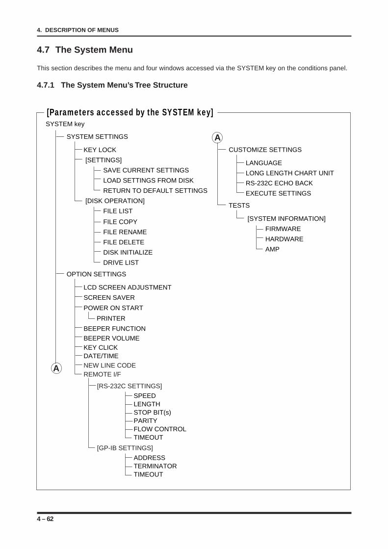
4 – 62
4. DESCRIPTION OF MENUS
4.7 The System Menu
This section describes the menu and four windows accessed via the SYSTEM key on the conditions panel.
4.7.1 The System Menu’s Tree Structure
SYSTEM SETTINGS
OPTION SETTINGS
KEY LOCK
[SETTINGS]
SAVE CURRENT SETTINGS
RETURN TO DEFAULT SETTINGS
[DISK OPERATION]
FILE LIST
LOAD SETTINGS FROM DISK
FILE COPY
FILE DELETE
DISK INITIALIZE
DRIVE LIST
FILE RENAME
LCD SCREEN ADJUSTMENT
SCREEN SAVER
POWER ON START
DATE/TIME
PRINTER
BEEPER FUNCTION
BEEPER VOLUMEKEY CLICK
CUSTOMIZE SETTINGS
LANGUAGE
LONG LENGTH CHART UNIT
RS-232C ECHO BACK
EXECUTE SETTINGS
TESTS
[SYSTEM INFORMATION]
FIRMWARE
HARDWARE
AMP
SYSTEM key
[Parameters accessed by the SYSTEM key]
A
A NEW LINE CODEREMOTE I/F
[RS-232C SETTINGS]
[GP-IB SETTINGS]
ADDRESSTERMINATORTIMEOUT
SPEEDLENGTHSTOP BIT(s)PARITYFLOW CONTROLTIMEOUT
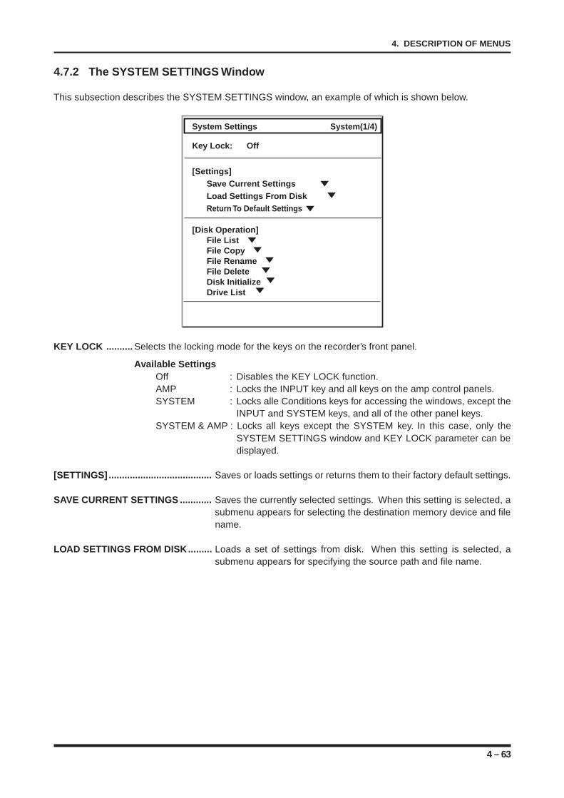
4 – 63
4. DESCRIPTION OF MENUS
4.7.2 The SYSTEM SETTINGS Window
This subsection describes the SYSTEM SETTINGS window, an example of which is shown below.
System Settings System(1/4)
Key Lock: Off
[Settings]Save Current SettingsLoad Settings From DiskReturn To Default Settings
[Disk Operation]File ListFile CopyFile RenameFile DeleteDisk InitializeDrive List
KEY LOCK .......... Selects the locking mode for the keys on the recorder’s front panel.
Available SettingsOff : Disables the KEY LOCK function.AMP : Locks the INPUT key and all keys on the amp control panels.SYSTEM : Locks alle Conditions keys for accessing the windows, except the
INPUT and SYSTEM keys, and all of the other panel keys.SYSTEM & AMP : Locks all keys except the SYSTEM key. In this case, only the
SYSTEM SETTINGS window and KEY LOCK parameter can bedisplayed.
[SETTINGS] ....................................... Saves or loads settings or returns them to their factory default settings.
SAVE CURRENT SETTINGS ............ Saves the currently selected settings. When this setting is selected, asubmenu appears for selecting the destination memory device and filename.
LOAD SETTINGS FROM DISK......... Loads a set of settings from disk. When this setting is selected, asubmenu appears for specifying the source path and file name.
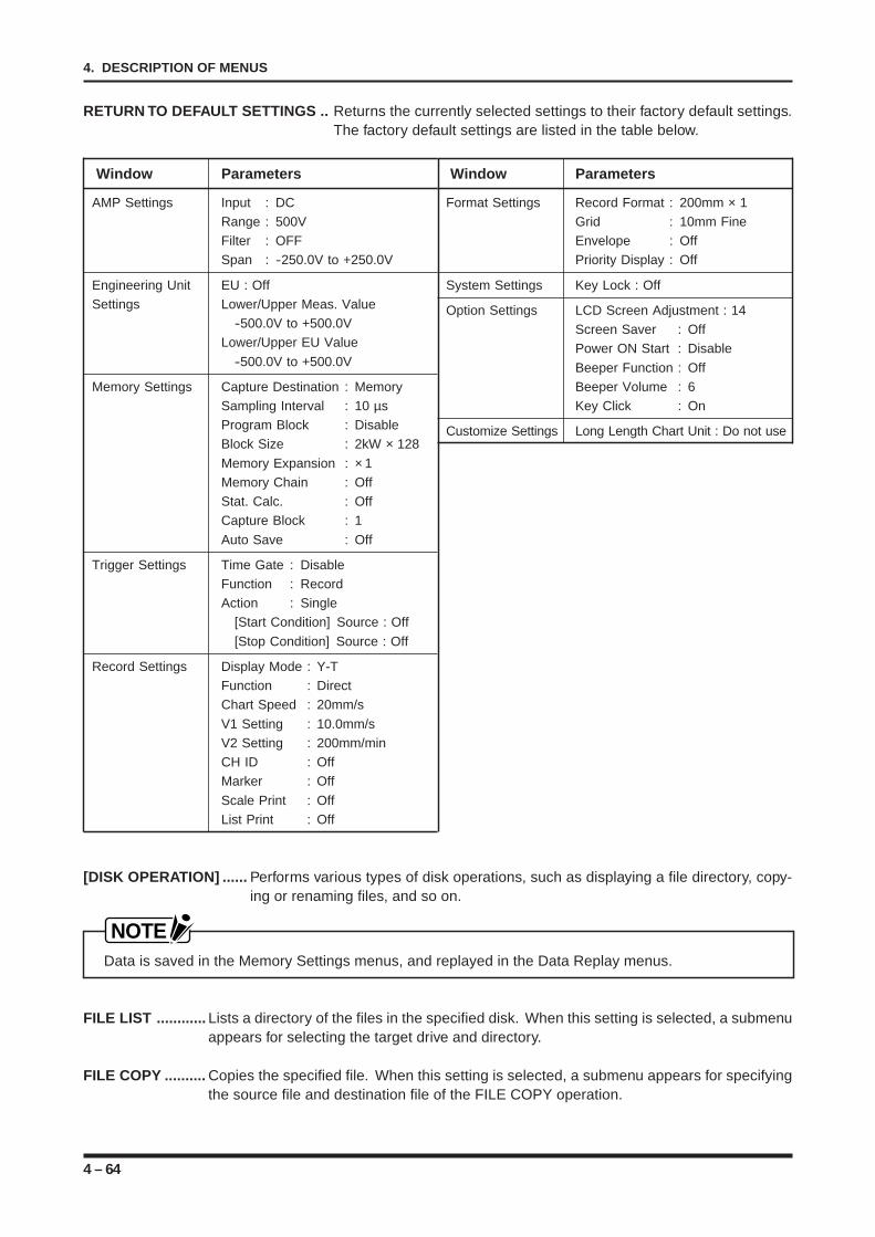
4 – 64
4. DESCRIPTION OF MENUS
RETURN TO DEFAULT SETTINGS .. Returns the currently selected settings to their factory default settings.The factory default settings are listed in the table below.
[DISK OPERATION] ...... Performs various types of disk operations, such as displaying a file directory, copy-ing or renaming files, and so on.
NOTEData is saved in the Memory Settings menus, and replayed in the Data Replay menus.
FILE LIST ............ Lists a directory of the files in the specified disk. When this setting is selected, a submenuappears for selecting the target drive and directory.
FILE COPY .......... Copies the specified file. When this setting is selected, a submenu appears for specifyingthe source file and destination file of the FILE COPY operation.
Window Parameters
AMP Settings Input : DCRange : 500VFilter : OFFSpan : -250.0V to +250.0V
Engineering Unit EU : OffSettings Lower/Upper Meas. Value
-500.0V to +500.0VLower/Upper EU Value
-500.0V to +500.0V
Memory Settings Capture Destination : MemorySampling Interval : 10 µsProgram Block : DisableBlock Size : 2kW × 128
Memory Expansion : × 1Memory Chain : OffStat. Calc. : OffCapture Block : 1
Auto Save : Off
Trigger Settings Time Gate : DisableFunction : RecordAction : Single
[Start Condition] Source : Off
[Stop Condition] Source : Off
Record Settings Display Mode : Y-TFunction : DirectChart Speed : 20mm/s
V1 Setting : 10.0mm/sV2 Setting : 200mm/minCH ID : OffMarker : Off
Scale Print : OffList Print : Off
Window Parameters
Format Settings Record Format : 200mm × 1Grid : 10mm FineEnvelope : OffPriority Display : Off
System Settings Key Lock : Off
Option Settings LCD Screen Adjustment : 14Screen Saver : OffPower ON Start : Disable
Beeper Function : OffBeeper Volume : 6Key Click : On
Customize Settings Long Length Chart Unit : Do not use
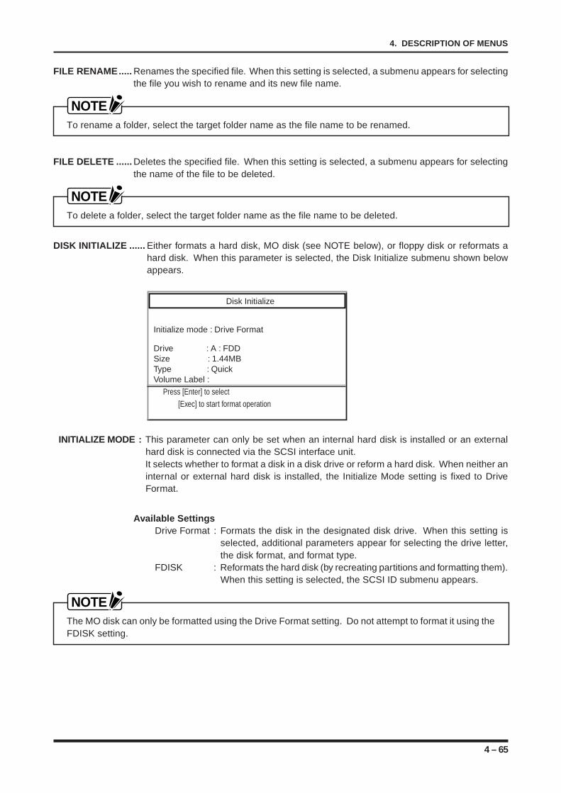
4 – 65
4. DESCRIPTION OF MENUS
FILE RENAME..... Renames the specified file. When this setting is selected, a submenu appears for selectingthe file you wish to rename and its new file name.
NOTETo rename a folder, select the target folder name as the file name to be renamed.
FILE DELETE ...... Deletes the specified file. When this setting is selected, a submenu appears for selectingthe name of the file to be deleted.
NOTETo delete a folder, select the target folder name as the file name to be deleted.
DISK INITIALIZE ...... Either formats a hard disk, MO disk (see NOTE below), or floppy disk or reformats ahard disk. When this parameter is selected, the Disk Initialize submenu shown belowappears.
Disk Initialize
Initialize mode : Drive Format
Drive : A : FDDSize : 1.44MBType : QuickVolume Label : Press [Enter] to select [Exec] to start format operation
INITIALIZE MODE : This parameter can only be set when an internal hard disk is installed or an externalhard disk is connected via the SCSI interface unit.It selects whether to format a disk in a disk drive or reform a hard disk. When neither aninternal or external hard disk is installed, the Initialize Mode setting is fixed to DriveFormat.
Available SettingsDrive Format : Formats the disk in the designated disk drive. When this setting is
selected, additional parameters appear for selecting the drive letter,the disk format, and format type.
FDISK : Reformats the hard disk (by recreating partitions and formatting them).When this setting is selected, the SCSI ID submenu appears.
NOTEThe MO disk can only be formatted using the Drive Format setting. Do not attempt to format it using theFDISK setting.
4 – 66
4. DESCRIPTION OF MENUS
Drive : This parameter, which can only be set when the Initialize Mode setting is DriveFormat, selects the drive to be formatted.
Available SettingsA : The floppy disk driveC through G : An internal hard diskH : MO driveI onward : An external memory device (connected via the SCSI interface
unit)
Size, Type : These parameters, which can only be set when the Initialize Mode set-ting is Drive Format, respectively select the disk format or type of format-ting method. The parameter displayed varies with the current Drive set-ting.
Available Settings• When the Drive setting is FDD, the Size setting can be set to 2DD format (720
Kbytes) or 2HD format (1.44 Mbytes).• When the Drive setting is MO Disk*1, the Type setting can be set to Quick or
Normal (the disk format is automatically recognized).• When the Drive setting is Hard Disk*2, the Type setting can be set to Quick or
Normal.*1 Only when the MO disk is installed.*2 Recognizable IBM-standard formats are 2128 Mbytes, 230 Mbytes, 540 Mbytes,
and 640 Mbytes (compatible with MS-DOS Version 5.1 or later).*4
*3 Only when using a hard disk recommended by Graphtec.*4 IBM is a registered trademark of International Business Machines Corp. MS-DOS
is a registered trademark of Microsoft Corporation.
Volume Label : This parameter, which can only be set when the Initialize Mode set-ting is Drive Format, specifies the volume label of the disk to be for-matted. Specify a volume label of up to 12 characters.
SCSI ID : This parameter, which can only be set when the Initialize Mode set-ting is FDISK, selects the ID number of the hard disk to be reformat-ted.
DRIVE LIST ......... When this setting is selected, a list of existing drives appears. If the SCSI interface unit isinstalled and is used to connect an MO disk drive or Zip drive as an external device, thedrive number of such devices will also be listed.
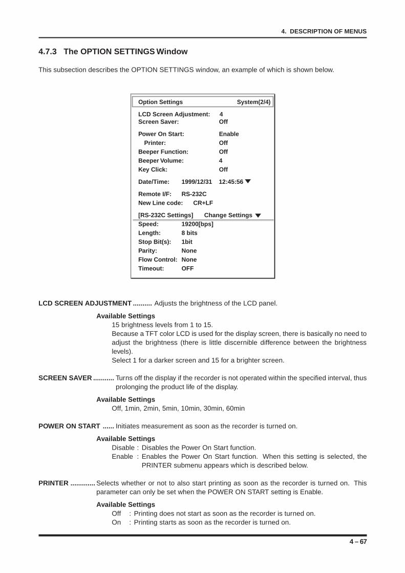
4 – 67
4. DESCRIPTION OF MENUS
4.7.3 The OPTION SETTINGS Window
This subsection describes the OPTION SETTINGS window, an example of which is shown below.
Option Settings System(2/4)
LCD Screen Adjustment: 4Screen Saver: Off
Power On Start: EnablePrinter: Off
Beeper Function: OffBeeper Volume: 4Key Click: Off
Date/Time: 1999/12/31 12:45:56
Remote I/F: RS-232CNew Line code: CR+LF
[RS-232C Settings] Change SettingsSpeed: 19200[bps]Length: 8 bitsStop Bit(s): 1bitParity: NoneFlow Control: NoneTimeout: OFF
LCD SCREEN ADJUSTMENT .......... Adjusts the brightness of the LCD panel.
Available Settings15 brightness levels from 1 to 15.Because a TFT color LCD is used for the display screen, there is basically no need toadjust the brightness (there is little discernible difference between the brightnesslevels).Select 1 for a darker screen and 15 for a brighter screen.
SCREEN SAVER ........... Turns off the display if the recorder is not operated within the specified interval, thusprolonging the product life of the display.
Available SettingsOff, 1min, 2min, 5min, 10min, 30min, 60min
POWER ON START ...... Initiates measurement as soon as the recorder is turned on.
Available SettingsDisable : Disables the Power On Start function.Enable : Enables the Power On Start function. When this setting is selected, the
PRINTER submenu appears which is described below.
PRINTER ............. Selects whether or not to also start printing as soon as the recorder is turned on. Thisparameter can only be set when the POWER ON START setting is Enable.
Available SettingsOff : Printing does not start as soon as the recorder is turned on.On : Printing starts as soon as the recorder is turned on.
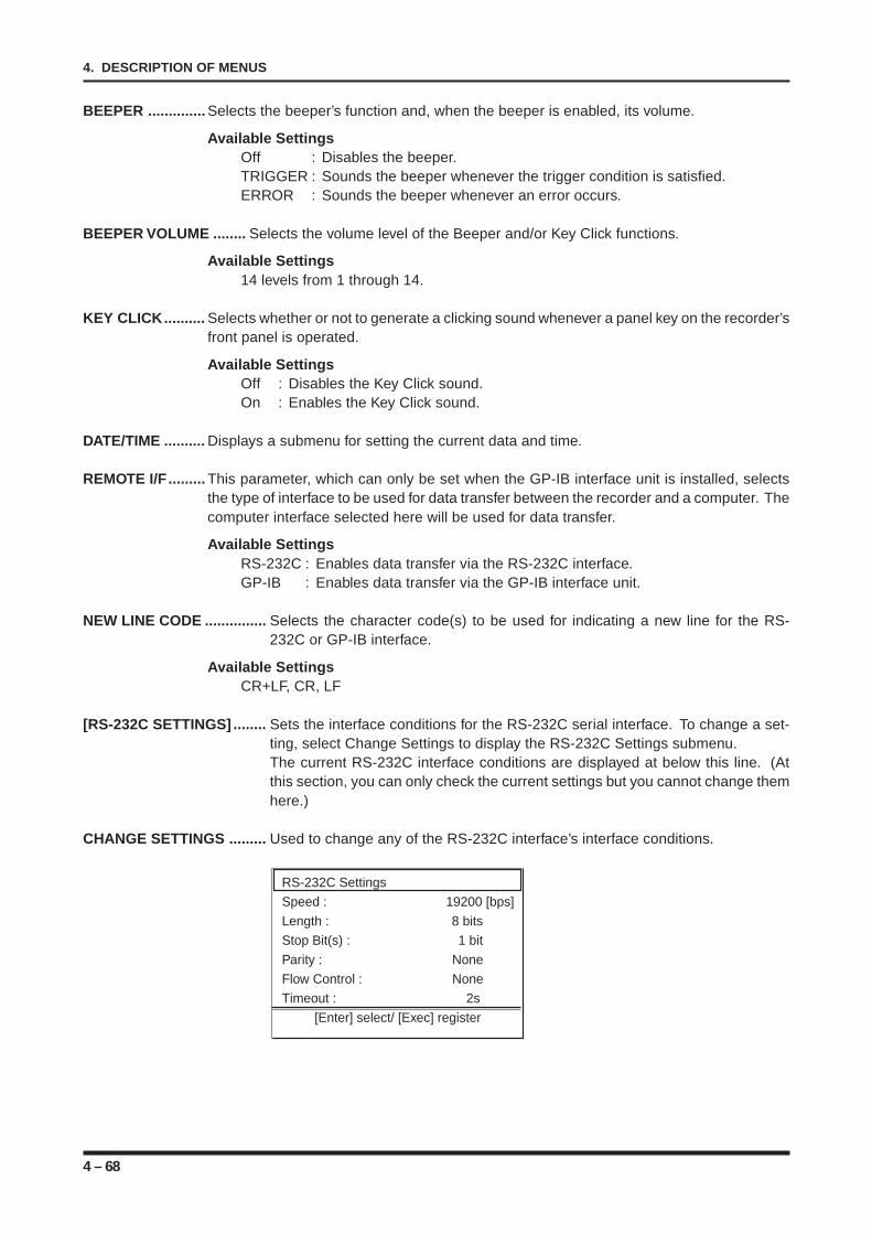
4 – 68
4. DESCRIPTION OF MENUS
BEEPER .............. Selects the beeper’s function and, when the beeper is enabled, its volume.
Available SettingsOff : Disables the beeper.TRIGGER : Sounds the beeper whenever the trigger condition is satisfied.ERROR : Sounds the beeper whenever an error occurs.
BEEPER VOLUME ........ Selects the volume level of the Beeper and/or Key Click functions.
Available Settings14 levels from 1 through 14.
KEY CLICK.......... Selects whether or not to generate a clicking sound whenever a panel key on the recorder’sfront panel is operated.
Available SettingsOff : Disables the Key Click sound.On : Enables the Key Click sound.
DATE/TIME .......... Displays a submenu for setting the current data and time.
REMOTE I/F ......... This parameter, which can only be set when the GP-IB interface unit is installed, selectsthe type of interface to be used for data transfer between the recorder and a computer. Thecomputer interface selected here will be used for data transfer.
Available SettingsRS-232C : Enables data transfer via the RS-232C interface.GP-IB : Enables data transfer via the GP-IB interface unit.
NEW LINE CODE ............... Selects the character code(s) to be used for indicating a new line for the RS-232C or GP-IB interface.
Available SettingsCR+LF, CR, LF
[RS-232C SETTINGS] ........ Sets the interface conditions for the RS-232C serial interface. To change a set-ting, select Change Settings to display the RS-232C Settings submenu.The current RS-232C interface conditions are displayed at below this line. (Atthis section, you can only check the current settings but you cannot change themhere.)
CHANGE SETTINGS ......... Used to change any of the RS-232C interface’s interface conditions.
RS-232C Settings
Speed : 19200 [bps]
Length : 8 bits
Stop Bit(s) : 1 bit
Parity : None
Flow Control : None
Timeout : 2s
[Enter] select/ [Exec] register
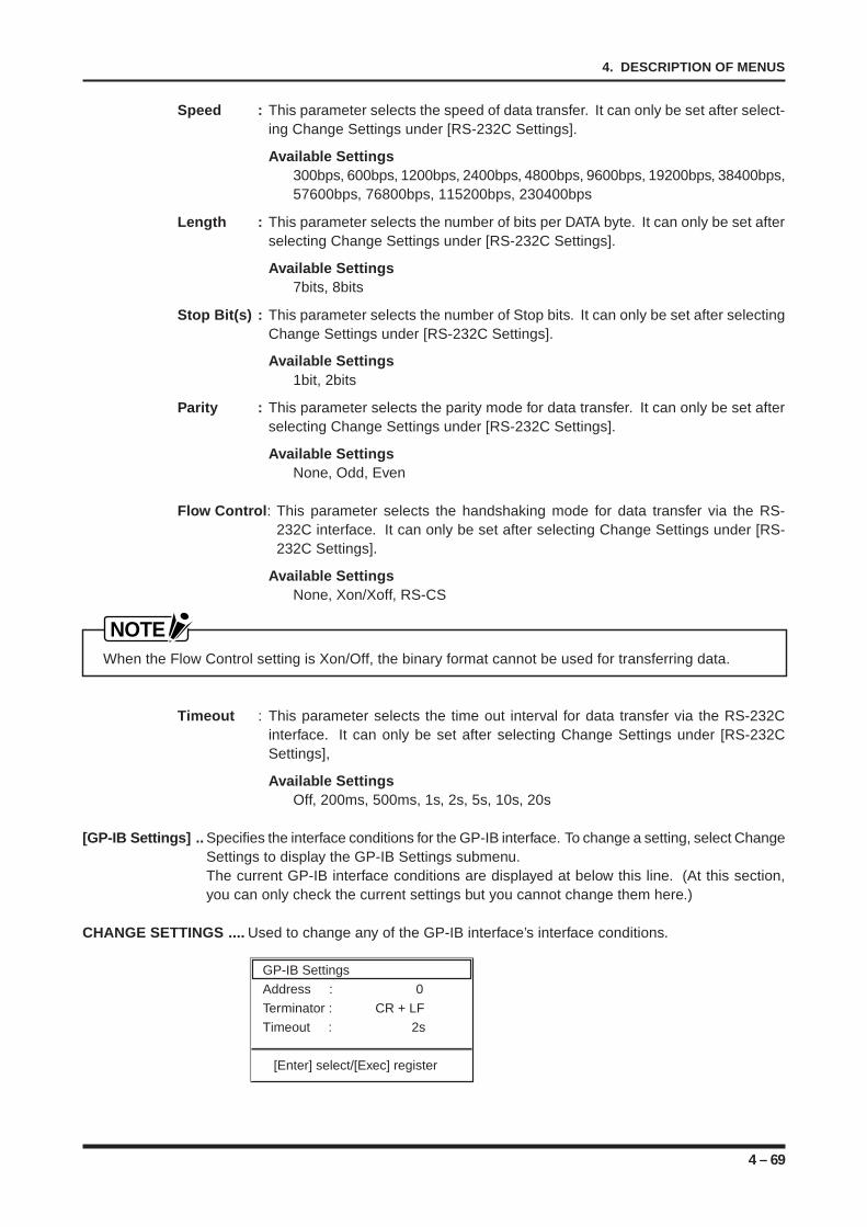
4 – 69
4. DESCRIPTION OF MENUS
Speed : This parameter selects the speed of data transfer. It can only be set after select-ing Change Settings under [RS-232C Settings].
Available Settings300bps, 600bps, 1200bps, 2400bps, 4800bps, 9600bps, 19200bps, 38400bps,57600bps, 76800bps, 115200bps, 230400bps
Length : This parameter selects the number of bits per DATA byte. It can only be set afterselecting Change Settings under [RS-232C Settings].
Available Settings7bits, 8bits
Stop Bit(s) : This parameter selects the number of Stop bits. It can only be set after selectingChange Settings under [RS-232C Settings].
Available Settings1bit, 2bits
Parity : This parameter selects the parity mode for data transfer. It can only be set afterselecting Change Settings under [RS-232C Settings].
Available SettingsNone, Odd, Even
Flow Control : This parameter selects the handshaking mode for data transfer via the RS-232C interface. It can only be set after selecting Change Settings under [RS-232C Settings].
Available SettingsNone, Xon/Xoff, RS-CS
NOTEWhen the Flow Control setting is Xon/Off, the binary format cannot be used for transferring data.
Timeout : This parameter selects the time out interval for data transfer via the RS-232Cinterface. It can only be set after selecting Change Settings under [RS-232CSettings],
Available SettingsOff, 200ms, 500ms, 1s, 2s, 5s, 10s, 20s
[GP-IB Settings] .. Specifies the interface conditions for the GP-IB interface. To change a setting, select ChangeSettings to display the GP-IB Settings submenu.The current GP-IB interface conditions are displayed at below this line. (At this section,you can only check the current settings but you cannot change them here.)
CHANGE SETTINGS .... Used to change any of the GP-IB interface’s interface conditions.
GP-IB Settings
Address : 0
Terminator : CR + LF
Timeout : 2s
[Enter] select/[Exec] register
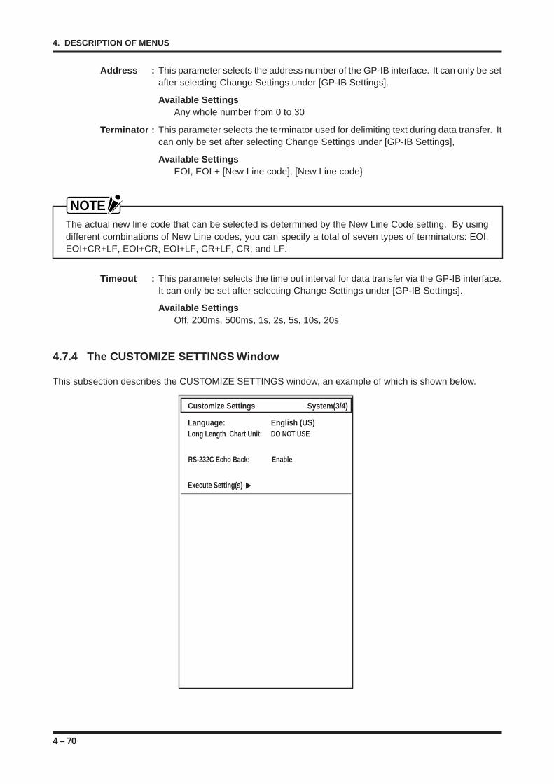
4 – 70
4. DESCRIPTION OF MENUS
Address : This parameter selects the address number of the GP-IB interface. It can only be setafter selecting Change Settings under [GP-IB Settings].
Available SettingsAny whole number from 0 to 30
Terminator : This parameter selects the terminator used for delimiting text during data transfer. Itcan only be set after selecting Change Settings under [GP-IB Settings],
Available SettingsEOI, EOI + [New Line code], [New Line code
NOTEThe actual new line code that can be selected is determined by the New Line Code setting. By usingdifferent combinations of New Line codes, you can specify a total of seven types of terminators: EOI,EOI+CR+LF, EOI+CR, EOI+LF, CR+LF, CR, and LF.
Timeout : This parameter selects the time out interval for data transfer via the GP-IB interface.It can only be set after selecting Change Settings under [GP-IB Settings].
Available SettingsOff, 200ms, 500ms, 1s, 2s, 5s, 10s, 20s
4.7.4 The CUSTOMIZE SETTINGS Window
This subsection describes the CUSTOMIZE SETTINGS window, an example of which is shown below.
Customize Settings System(3/4)
Language: English (US)Long Length Chart Unit: DO NOT USE
Execute Setting(s)
RS-232C Echo Back: Enable
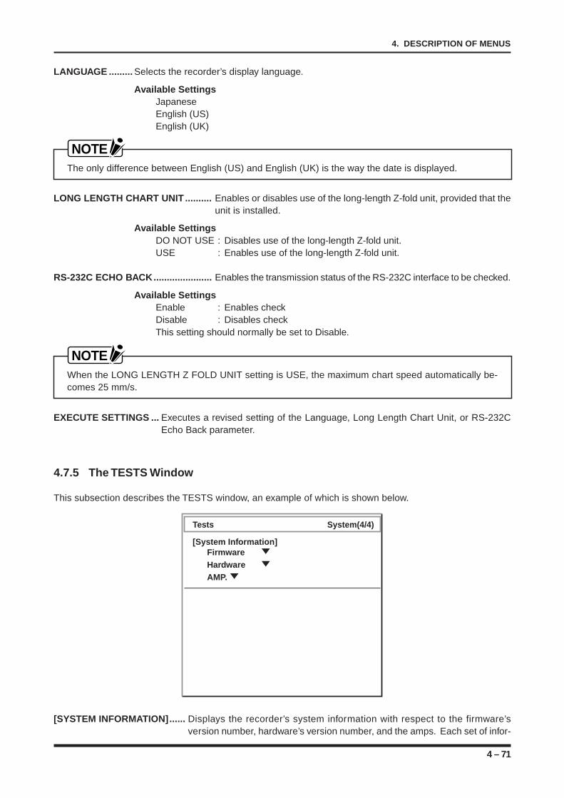
4 – 71
4. DESCRIPTION OF MENUS
LANGUAGE ......... Selects the recorder’s display language.
Available SettingsJapaneseEnglish (US)English (UK)
NOTEThe only difference between English (US) and English (UK) is the way the date is displayed.
LONG LENGTH CHART UNIT .......... Enables or disables use of the long-length Z-fold unit, provided that theunit is installed.
Available SettingsDO NOT USE : Disables use of the long-length Z-fold unit.USE : Enables use of the long-length Z-fold unit.
RS-232C ECHO BACK...................... Enables the transmission status of the RS-232C interface to be checked.
Available SettingsEnable : Enables checkDisable : Disables checkThis setting should normally be set to Disable.
NOTEWhen the LONG LENGTH Z FOLD UNIT setting is USE, the maximum chart speed automatically be-comes 25 mm/s.
EXECUTE SETTINGS ... Executes a revised setting of the Language, Long Length Chart Unit, or RS-232CEcho Back parameter.
4.7.5 The TESTS Window
This subsection describes the TESTS window, an example of which is shown below.
Tests System(4/4))
[System Information]FirmwareHardwareAMP.
[SYSTEM INFORMATION]...... Displays the recorder’s system information with respect to the firmware’sversion number, hardware’s version number, and the amps. Each set of infor-
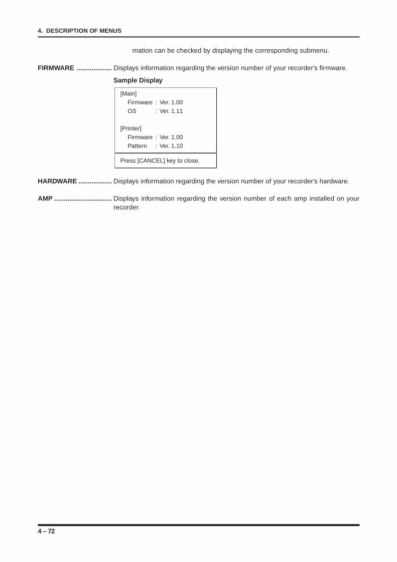
4 – 72
4. DESCRIPTION OF MENUS
mation can be checked by displaying the corresponding submenu.
FIRMWARE ................... Displays information regarding the version number of your recorder’s firmware.
Sample Display
[Main]
Firmware : Ver. 1.00
OS : Ver. 1.11
[Printer]
Firmware : Ver. 1.00
Pattern : Ver. 1.10
Press [CANCEL] key to close.
HARDWARE .................. Displays information regarding the version number of your recorder’s hardware.
AMP ............................... Displays information regarding the version number of each amp installed on yourrecorder.
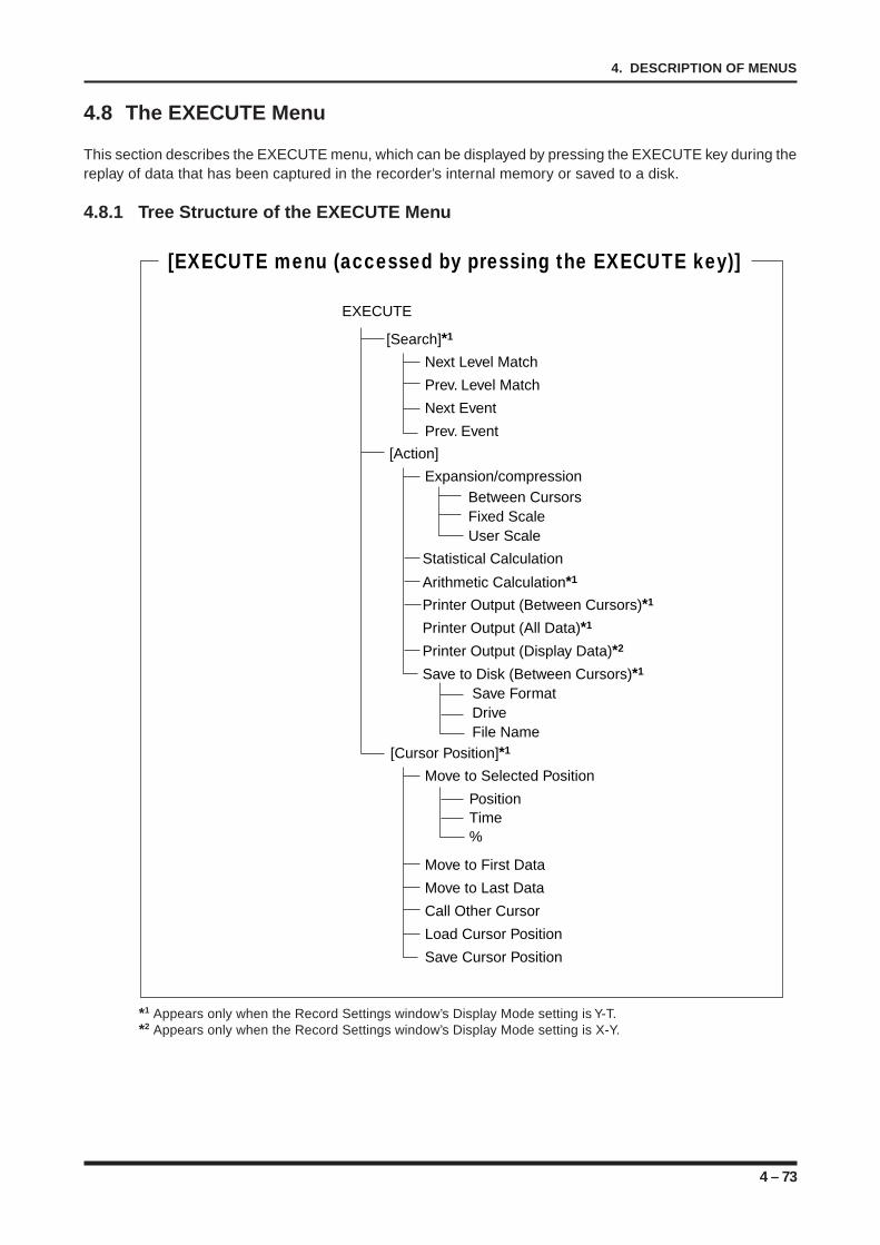
4 – 73
4. DESCRIPTION OF MENUS
4.8 The EXECUTE Menu
This section describes the EXECUTE menu, which can be displayed by pressing the EXECUTE key during thereplay of data that has been captured in the recorder’s internal memory or saved to a disk.
4.8.1 Tree Structure of the EXECUTE Menu
EXECUTE
[Action]
Expansion/compression
Printer Output (Between Cursors)*1
Printer Output (All Data)*1
Printer Output (Display Data)*2
Save to Disk (Between Cursors)*1
Between CursorsFixed ScaleUser Scale
Save FormatDrive File Name
[Cursor Position]*1
Move to Selected Position
Move to First Data
Move to Last Data
Call Other Cursor
Load Cursor Position
Save Cursor Position
Position Time %
[Search]*1
Next Level Match
Prev. Level Match
Next Event
Prev. Event
[EXECUTE menu (accessed by pressing the EXECUTE key)]
Statistical Calculation
Arithmetic Calculation*1
*1 Appears only when the Record Settings window’s Display Mode setting is Y-T.*2 Appears only when the Record Settings window’s Display Mode setting is X-Y.
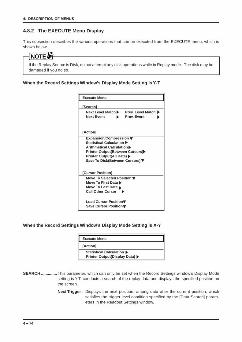
4 – 74
4. DESCRIPTION OF MENUS
4.8.2 The EXECUTE Menu Display
This subsection describes the various operations that can be executed from the EXECUTE menu, which isshown below.
NOTEIf the Replay Source is Disk, do not attempt any disk operations while in Replay mode. The disk may bedamaged if you do so.
When the Record Settings Window’s Display Mode Setting is Y-T
Execute Menu
[Search]Next Level Match Prev. Level MatchNext Event Prev. Event
[Action]
Expansion/CompressionStatistical CalculationArithmetical CalculationPrinter Output(Between Cursors)Printer Output(All Data)Save To Disk(Between Cursors)
[Cursor Position]Move To Selected PositionMove To First DataMove To Last DataCall Other Cursor
Load Cursor PositionSave Cursor Position
When the Record Settings Window’s Display Mode Setting is X-Y
Execute Menu
[Action]
Statistical CalculationPrinter Output(Display Data)
SEARCH .............. This parameter, which can only be set when the Record Settings window’s Display Modesetting is Y-T, conducts a search of the replay data and displays the specified position onthe screen.
Next Trigger : Displays the next position, among data after the current position, whichsatisfies the trigger level condition specified by the [Data Search] param-eters in the Readout Settings window.
4 – 75
4. DESCRIPTION OF MENUS
Prev. Trigger : Displays the previous position, among data before the current position, whichsatisfies the trigger level condition specified by the [Data Search] param-eters in the Readout Settings window.
Next Event* : Displays the next event marker position after the current position.This function, however, can only be used when event markers have beencaptured along with the measured data during data capture in the followcase:• The Capture Destination setting is Disk (The Replay Source setting at the
Memory Settings window is Disk); and• The Event setting at the Memory Settings window is On to enable cap-
ture of event data (this Event function is displayed only when the ReplaySource setting is Disk).
Prev. Event* : Displays the previous event marker position before the current position.This function, however, can only be used when event markers have beencaptured along with the measured data during data capture in the followcase:• The Capture Destination setting is Disk (The Replay Source setting at the
Memory Settings window is Disk); and• The Event setting at the Memory Settings window is On to enable cap-
ture of event data (this Event function is displayed only when the ReplaySource setting is Disk).
* The input of event marker data is based on a logical OR operation between input via the REMOTEinterface or input by the main control panel’s MODE/EVENT key.
ACTION ............... Performs various operations for waveforms, such as expansion, compression, printout,and calculation.
Expansion/Compression : Expands or compresses the display of waveforms being re-played.
Available SettingsBetween Cursors : Expands or compresses the cursor-defined segment of the wave-
form display to fit the screen’s width.Fixed Scale : Expands or compresses the waveform by the ratio selected from
the choices below.Expansion : Can be set to any integer from 1 to 10.Compression : Can be set to any fraction with a numerator of 1
from 1/1 to 1/1000.
User Scale : Expands or compresses the waveform by the desired magnifica-tion ratio from 1/1000 to 10×.The User Scale value is specified as the time unit per division.
Stat. Calc . : Performs an Area Statistical Calculation operation on the cursor-definedportion of a waveform. The type of calculation used is determined by theFunction setting under [Area Statistical Calculation] in the Readout Settingswindow.
Arith. Calc. : This parameter, which can only be set when the Record Settings window’sDisplay Mode setting is Y-T, performs an arithmetic operation on the cursor-defined portion of a waveform. The type of operation used is determined bythe Formula Settings in the Calculation Settings window.
4 – 76
4. DESCRIPTION OF MENUS
Printer Output (Between Cursors) : This parameter, which can only be set when theRecord Settings window’s Display Mode setting isY-T, prints the cursor-defined segment of the wave-form display onto chart paper.
Printer Output (All Data) : This parameter, which can only be set when theRecord Settings window’s Display Mode setting isY-T, prints all waveform data being replayed ontochart paper.
Printer Output (Display Data) : This parameter, which can only be set when theRecord Settings window’s Display Mode setting isX-Y, prints out the data being replayed onto chartpaper in a 200 × 200 mm format.
Save to Disk (Between Cursors) : This parameter, which can only be set when theRecord Settings window’s Display Mode setting isY-T, saves the cursor-defined segment of the wave-form display to a disk either in an internal disk drive(a hard disk drive*1, floppy disk, or MO drive*2) or inan external memory device connected via the SCSIinterface unit*3.
*1 Only when the 31/2” hard disk drive is installed.*2 Only when the MO drive is installed (either an MO drive or floppy disk drive can be installed in the
slot provided).*3 Only when the SCSI interface unit is installed.
CURSOR POSITION ..... This parameter, which can only be set when the Record Settings window’s DisplayMode setting is Y-T, moves the cursor to the selected position within the data beingreplayed, loads/saves the cursor position, and so on.
Move to Selected Position : Moves the cursor to the selected position within the databeing replayed using one of three methods.
Available SettingsPosition : Moves the cursor to the position of the specified time from the current position.Time : Moves the cursor to the position of the specified time. Specify a time that
was captured along with the measured data during data capture.% : Moves the cursor to the position specified as a percentage of the entire
data (which represents 100%).
Move to First Data : Moves the cursor to the beginning of the data being replayed.
Move to Last Data : Moves the cursor to the end of the data being replayed.
Call Other Cursor : Summons the other cursor within the same screen as the cur-rently displayed cursor.
Load Cursor Position : Loads a previously saved cursor position and then moves thecursor to that position.
Save Cursor Position : Saves the cursor’s current position. The cursor position is savedunder the name of “Position number: n.” Up to 10 cursor posi-tions can be saved.
5 – 1
5. SIMPLIFIED RECORDING IN REALTIME
SIMPLIFIED RECORDING IN REALTIME
This chapter provides instructions for simplified Directrecording, that is, for directly initiating realtime record-ing using the panel keys.
5.1 Overall Flow of the Setting Procedure5.2 Enabling Simplified Direct Recording
CHAPTER 5CHAPTER 5
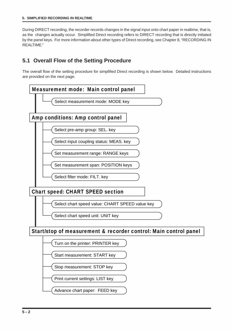
5 – 2
5. SIMPLIFIED RECORDING IN REALTIME
During DIRECT recording, the recorder records changes in the signal input onto chart paper in realtime, that is,as the changes actually occur. Simplified Direct recording refers to DIRECT recording that is directly initiatedby the panel keys. For more information about other types of Direct recording, see Chapter 8, “RECORDING INREALTIME.”
5.1 Overall Flow of the Setting Procedure
The overall flow of the setting procedure for simplified Direct recording is shown below. Detailed instructionsare provided on the next page.
Amp conditions: Amp control panel
Select pre-amp group: SEL. key
Select input coupling status: MEAS. key
Set measurement range: RANGE keys
Set measurement span: POSITION keys
Select filter mode: FILT. key
Chart speed: CHART SPEED section
Select chart speed value: CHART SPEED value key
Select chart speed unit: UNIT key
Start/stop of measurement & recorder control: Main control panel
Turn on the printer: PRINTER key
Start measurement: START key
Stop measurement: STOP key
Print current settings: LIST key
Advance chart paper: FEED key
Measurement mode: Main control panel
Select measurement mode: MODE key
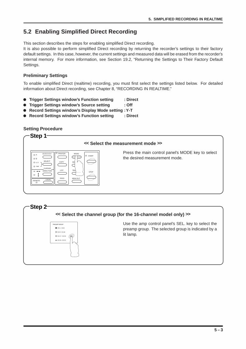
5 – 3
5. SIMPLIFIED RECORDING IN REALTIME
5.2 Enabling Simplified Direct Recording
This section describes the steps for enabling simplified Direct recording.It is also possible to perform simplified Direct recording by returning the recorder’s settings to their factorydefault settings. In this case, however, the current settings and measured data will be erased from the recorder’sinternal memory. For more information, see Section 19.2, “Returning the Settings to Their Factory DefaultSettings.
Preliminary Settings
To enable simplified Direct (realtime) recording, you must first select the settings listed below. For detailedinformation about Direct recording, see Chapter 8, “RECORDING IN REALTIME.”
Trigger Settings window’s Function setting : DirectTrigger Settings window’s Source setting : OffRecord Settings window’s Display Mode setting : Y-TRecord Settings window’s Function setting : Direct
Setting Procedure
Step 2<< Select the channel group (for the 16-channel model only) >>
Use the amp control panel’s SEL. key to select thepreamp group. The selected group is indicated by alit lamp.
PREAMP GROUP
CH 1 - CH 8
CH 9 - CH 16
CH 17 - CH 24
CH 24 - CH 32
SEL.
Press the main control panel’s MODE key to selectthe desired measurement mode.
Step 1<< Select the measurement mode >>
MODE/EVENT
SELECT
A
B
A, B
A&B
PRINTER
COPY
LIST
FEED
MODE
MONITOR
TRIGGER
MEM.OUT
START
STOP
LOCALREMOTE
CURSOR
DIRECTION
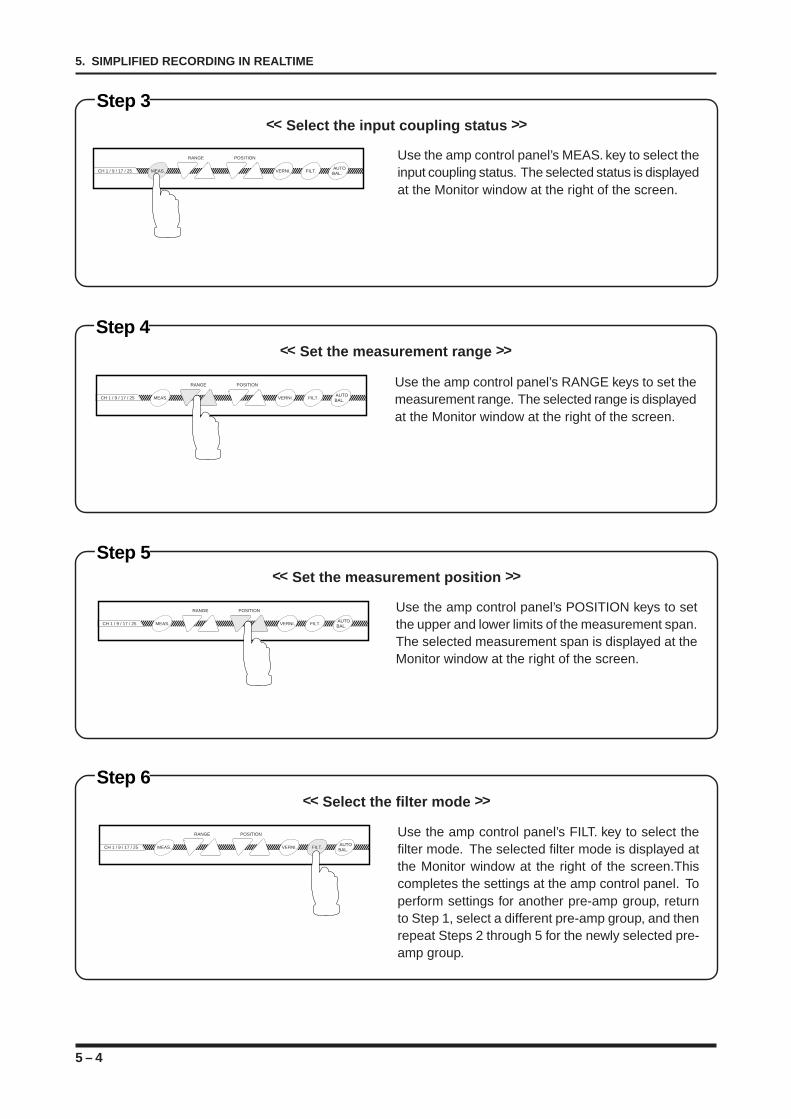
5 – 4
5. SIMPLIFIED RECORDING IN REALTIME
Step 5<< Set the measurement position >>
Step 6<< Select the filter mode >>
Use the amp control panel’s POSITION keys to setthe upper and lower limits of the measurement span.The selected measurement span is displayed at theMonitor window at the right of the screen.
Use the amp control panel’s FILT. key to select thefilter mode. The selected filter mode is displayed atthe Monitor window at the right of the screen.Thiscompletes the settings at the amp control panel. Toperform settings for another pre-amp group, returnto Step 1, select a different pre-amp group, and thenrepeat Steps 2 through 5 for the newly selected pre-amp group.
CH 1 / 9 / 17 / 25 MEAS. VERNI. FILT. AUTO
BAL.
POSITIONRANGE
CH 1 / 9 / 17 / 25 MEAS. VERNI. FILT. AUTO
BAL.
POSITIONRANGE
Step 3<< Select the input coupling status >>
Use the amp control panel’s MEAS. key to select theinput coupling status. The selected status is displayedat the Monitor window at the right of the screen.
Step 4<< Set the measurement range >>
CH 1 / 9 / 17 / 25 MEAS. VERNI. FILT. AUTO
BAL.
POSITIONRANGE
CH 1 / 9 / 17 / 25 MEAS. VERNI. FILT. AUTO
BAL.
POSITIONRANGE Use the amp control panel’s RANGE keys to set themeasurement range. The selected range is displayedat the Monitor window at the right of the screen.
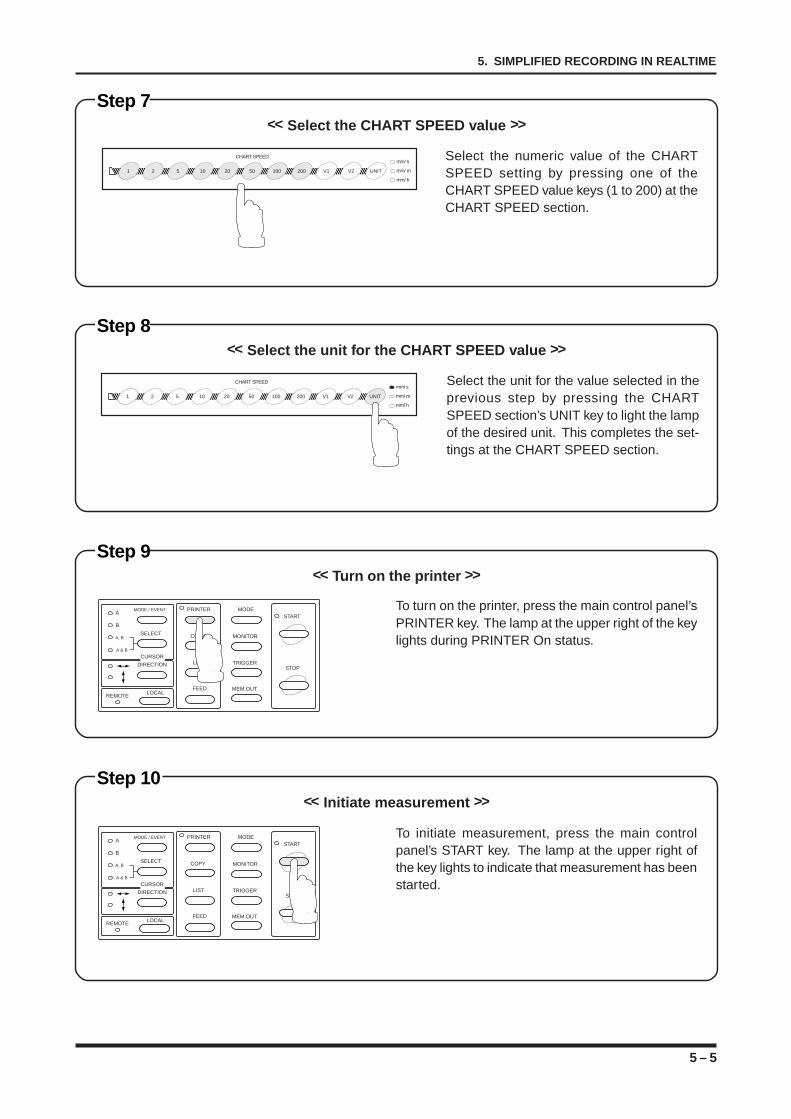
5 – 5
5. SIMPLIFIED RECORDING IN REALTIME
Step 7<< Select the CHART SPEED value >>
Step 8<< Select the unit for the CHART SPEED value >>
Select the numeric value of the CHARTSPEED setting by pressing one of theCHART SPEED value keys (1 to 200) at theCHART SPEED section.
Select the unit for the value selected in theprevious step by pressing the CHARTSPEED section’s UNIT key to light the lampof the desired unit. This completes the set-tings at the CHART SPEED section.
1 2 5 10 20 50 100 200 V1 V2 UNIT
mm/ s
mm/ m
mm/ h
CHART SPEED
1 2 5 10 20 50 100 200 V1 V2 UNIT
mm/ s
mm/ m
mm/ h
CHART SPEED
Step 9<< Turn on the printer >>
Step 10<< Initiate measurement >>
To turn on the printer, press the main control panel’sPRINTER key. The lamp at the upper right of the keylights during PRINTER On status.
To initiate measurement, press the main controlpanel’s START key. The lamp at the upper right ofthe key lights to indicate that measurement has beenstarted.
MODE / EVENT
SELECT
A
B
A, B
A & B
PRINTER
COPY
LIST
FEED
MODE
MONITOR
TRIGGER
MEM.OUT
START
STOP
LOCALREMOTE
CURSOR
DIRECTION
MODE / EVENT
SELECT
A
B
A, B
A & B
PRINTER
COPY
LIST
FEED
MODE
MONITOR
TRIGGER
MEM.OUT
START
STOP
LOCALREMOTE
CURSOR
DIRECTION
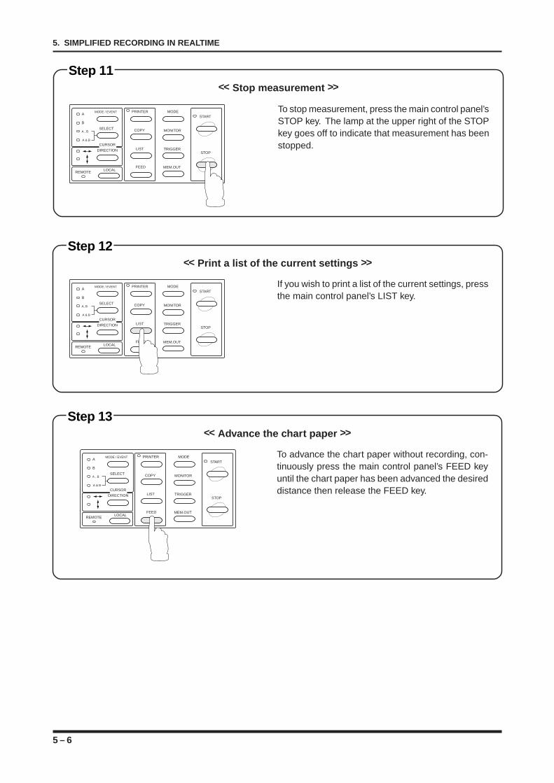
5 – 6
5. SIMPLIFIED RECORDING IN REALTIME
Step 13<< Advance the chart paper >>
To advance the chart paper without recording, con-tinuously press the main control panel’s FEED keyuntil the chart paper has been advanced the desireddistance then release the FEED key.
MODE / EVENT
SELECT
A
B
A , B
A & B
PRINTER
COPY
LIST
FEED
MODE
MONITOR
TRIGGER
MEM.OUT
START
STOP
LOCALREMOTE
CURSOR
DIRECTION
Step 11<< Stop measurement >>
Step 12<< Print a list of the current settings >>
To stop measurement, press the main control panel’sSTOP key. The lamp at the upper right of the STOPkey goes off to indicate that measurement has beenstopped.
If you wish to print a list of the current settings, pressthe main control panel’s LIST key.
MODE / EVENT
SELECT
A
B
A , B
A & B
PRINTER
COPY
LIST
FEED
MODE
MONITOR
TRIGGER
MEM.OUT
START
STOP
LOCALREMOTE
CURSOR
DIRECTION
MODE / EVENT
SELECT
A
B
A, B
A & B
PRINTER
COPY
LIST
FEED
MODE
MONITOR
TRIGGER
MEM.OUT
START
STOP
LOCALREMOTE
CURSOR
DIRECTION
6 – 1
6. FLOW OF SETTING OPERATIONS
CHAPTER 6CHAPTER 6FLOW OF SETTING OPERATIONS
This chapter describes the general flow of settingoperations.
6.1 Flow of Setting Operations
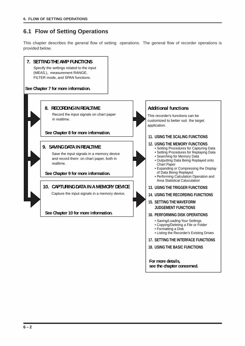
6 – 2
6. FLOW OF SETTING OPERATIONS
6.1 Flow of Setting Operations
This chapter describes the general flow of setting operations. The general flow of recorder operations isprovided below.
Additional functions
11. USING THE SCALING FUNCTIONS
12. USING THE MEMORY FUNCTIONS• Setting Procedures for Capturing Data• Setting Procedures for Replaying Data• Searching for Memory Data• Outputting Data Being Replayed onto
Chart Paper• Expanding or Compressing the Display
of Data Being Replayed• Performing Calculation Operation and
Area Statistical Caluculation
13. USING THE TRIGGER FUNCTIONS
14. USING THE RECORDING FUNCTIONS
15. SETTING THE WAVEFORM
JUDGEMENT FUNCTIONS
16. PERFORMING DISK OPERATIONS • Saving/Loading Your Settings• Copying/Deleting a File or Folder• Formatting a Disk• Listing the Recorder’s Existing Drives
17. SETTING THE INTERFACE FUNCTIONS
18. USING THE BASIC FUNCTIONS
8. RECORDING IN REALTIMERecord the input signals on chart paper in realtime.
9. SAVING DATA IN REALTIMESave the input signals in a memory device and record them on chart paper, both in realtime.
10. CAPTURING DATA IN A MEMORY DEVICECapture the input signals in a memory device.
This recorder’s functions can be customized to better suit the target application.
See Chapter 10 for more information.
For more details, see the chapter concerned.
See Chapter 9 for more information.
See Chapter 8 for more information.
7. SETTING THE AMP FUNCTIONSSpecify the settings related to the input (MEAS.), measurement RANGE, FILTER mode, and SPAN functions.
See Chapter 7 for more information.
7 – 1
7. SETTING THE AMP FUNCTIONS
CHAPTER 7CHAPTER 7SETTING THE AMP FUNCTIONS
This chapter describes the procedural flow for settingamp-related settings.
7.1 Opening the AMP SETTINGS Window7.2 Selecting the Input Coupling (MEAS.) Type7.3 Setting the Measurement RANGE7.4 Selecting the FILTER Mode7.5 Setting the Measurement SPAN7.6 Setting the Logic Amp’s Conditions7.7 Setting the VERNIER Function
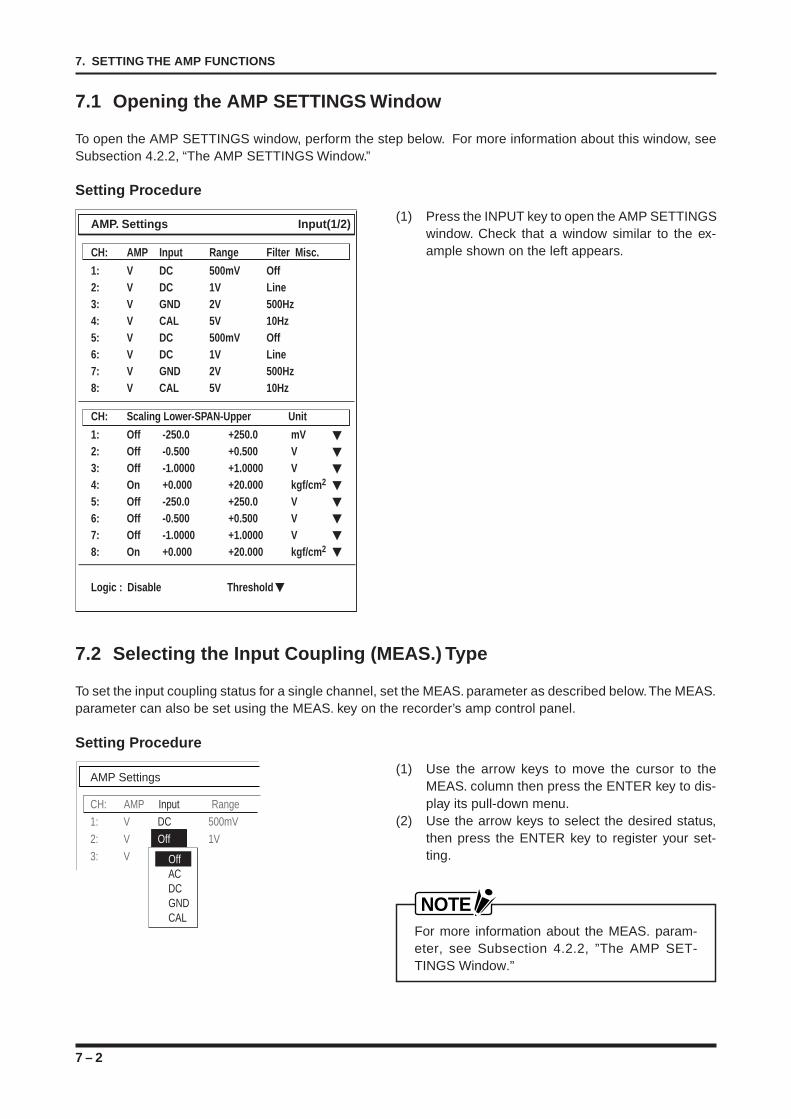
7 – 2
7. SETTING THE AMP FUNCTIONS
7.1 Opening the AMP SETTINGS Window
To open the AMP SETTINGS window, perform the step below. For more information about this window, seeSubsection 4.2.2, “The AMP SETTINGS Window.”
Setting Procedure
(1) Press the INPUT key to open the AMP SETTINGSwindow. Check that a window similar to the ex-ample shown on the left appears.
7.2 Selecting the Input Coupling (MEAS.) Type
To set the input coupling status for a single channel, set the MEAS. parameter as described below. The MEAS.parameter can also be set using the MEAS. key on the recorder’s amp control panel.
Setting Procedure
(1) Use the arrow keys to move the cursor to theMEAS. column then press the ENTER key to dis-play its pull-down menu.
(2) Use the arrow keys to select the desired status,then press the ENTER key to register your set-ting.
NOTEFor more information about the MEAS. param-eter, see Subsection 4.2.2, ”The AMP SET-TINGS Window.”
AMP Settings
CH: AMP Input Range
1: V DC 500mV
2: V Off 1V
3: V GNDOffACDCGNDCAL
AMP. Settings Input(1/2)
CH: AMP Input Range Filter Misc.
1: V DC 500mV Off2: V DC 1V Line3: V GND 2V 500Hz4: V CAL 5V 10Hz5: V DC 500mV Off6: V DC 1V Line7: V GND 2V 500Hz8: V CAL 5V 10Hz
CH: Scaling Lower-SPAN-Upper Unit
1: Off -250.0 +250.0 mV2: Off -0.500 +0.500 V3: Off -1.0000 +1.0000 V4: On +0.000 +20.000 kgf/cm2
5: Off -250.0 +250.0 V6: Off -0.500 +0.500 V7: Off -1.0000 +1.0000 V8: On +0.000 +20.000 kgf/cm2
Logic : Disable Threshold
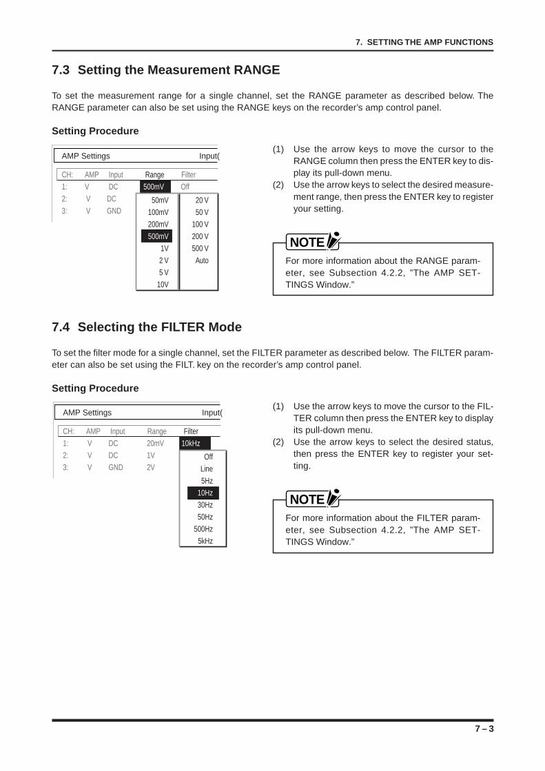
7 – 3
7. SETTING THE AMP FUNCTIONS
7.3 Setting the Measurement RANGE
To set the measurement range for a single channel, set the RANGE parameter as described below. TheRANGE parameter can also be set using the RANGE keys on the recorder’s amp control panel.
Setting Procedure
(1) Use the arrow keys to move the cursor to theRANGE column then press the ENTER key to dis-play its pull-down menu.
(2) Use the arrow keys to select the desired measure-ment range, then press the ENTER key to registeryour setting.
NOTEFor more information about the RANGE param-eter, see Subsection 4.2.2, ”The AMP SET-TINGS Window.”
7.4 Selecting the FILTER Mode
To set the filter mode for a single channel, set the FILTER parameter as described below. The FILTER param-eter can also be set using the FILT. key on the recorder’s amp control panel.
Setting Procedure
(1) Use the arrow keys to move the cursor to the FIL-TER column then press the ENTER key to displayits pull-down menu.
(2) Use the arrow keys to select the desired status,then press the ENTER key to register your set-ting.
NOTEFor more information about the FILTER param-eter, see Subsection 4.2.2, ”The AMP SET-TINGS Window.”
AMP Settings Input(
CH: AMP Input Range Filter
1: V DC 500mV Off
2: V DC 1V Line
3: V GND 2V 500Hz50mV 20 V
100mV 50 V
200mV 100 V
500mV 200 V
1V 5500 V
2 V Auto
5 V
10V
AMP Settings Input(
CH: AMP Input Range Filter
1: V DC 20mV 10kHz
2: V DC 1V Line
3: V GND 2V 500HzOff
Line
5Hz
10Hz
30Hz
50Hz
500Hz
5kHz
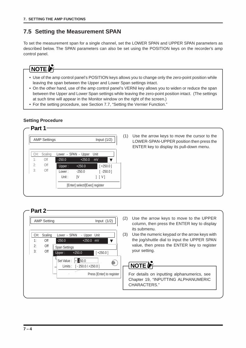
7 – 4
7. SETTING THE AMP FUNCTIONS
7.5 Setting the Measurement SPAN
To set the measurement span for a single channel, set the LOWER SPAN and UPPER SPAN parameters asdescribed below. The SPAN parameters can also be set using the POSITION keys on the recorder’s ampcontrol panel.
NOTE• Use of the amp control panel’s POSITION keys allows you to change only the zero-point position while
leaving the span between the Upper and Lower Span settings intact.• On the other hand, use of the amp control panel’s VERNI key allows you to widen or reduce the span
between the Upper and Lower Span settings while leaving the zero-point position intact. (The settingsat such time will appear in the Monitor window on the right of the screen.)
• For the setting procedure, see Section 7.7, “Setting the Vernier Function.”
Setting Procedure
Part 1
Part 2
CH: Scaling Lower - SPAN - Upper Unit
1: Off --250.0 +250.0 mV
2: Off
3: Off
[Enter] select/[Exec] register
Upper : +250.0 [ +250.0 ]
Lower : -250.0 [ -250.0 ]
Unit : [V ] [ V ]
AMP Settings Input (1/2)
CH: Scaling Lower - SPAN - Upper Unit
1: Off -250.0 +250.0 mV
2: Off
3: Off
AMP Setting Input (1/2)
[Enter] select/[Exec] register
Span Settings
Upper : +250.0 [ +250.0 ]
Lower : -250.0 [ -250.0 ]
Unit : [V ] [ V ]
Press [Enter] to register
Set Value : + 250.0
Limits : [ - 250.0 / +250.0 ]
(1) Use the arrow keys to move the cursor to theLOWER-SPAN-UPPER position then press theENTER key to display its pull-down menu.
(2) Use the arrow keys to move to the UPPERcolumn, then press the ENTER key to displayits submenu.
(3) Use the numeric keypad or the arrow keys withthe jog/shuttle dial to input the UPPER SPANvalue, then press the ENTER key to registeryour setting.
NOTEFor details on inputting alphanumerics, seeChapter 19, “INPUTTING ALPHANUMERICCHARACTERS.”
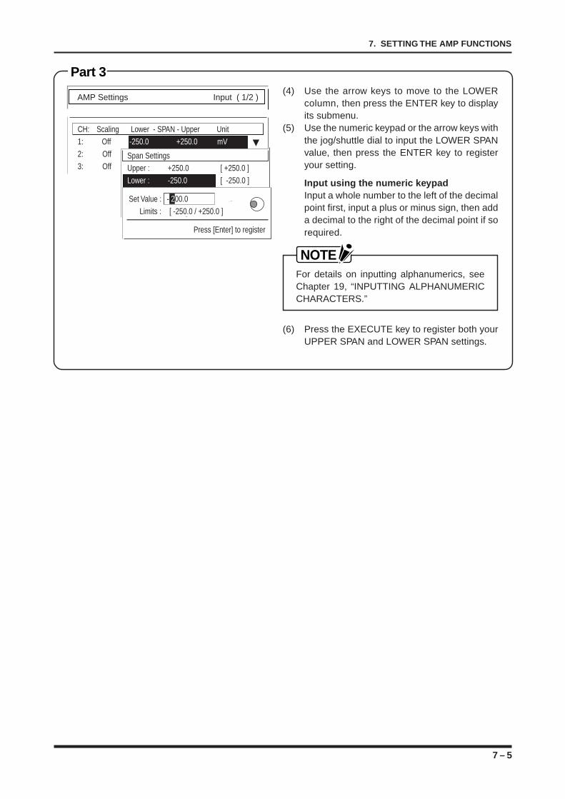
7 – 5
7. SETTING THE AMP FUNCTIONS
Part 3
CH: Scaling Lower - SPAN - Upper Unit
1: Off -250.0 +250.0 mV
2: Off
3: Off
AMP Settings Input ( 1/2 )
[Enter] select/[Exec] register
Span Settings
Upper : +250.0 [ +250.0 ]
Lower : -250.0 [ -250.0 ]
Unit : [V ] [ V ]
Press [Enter] to register
Set Value : - 200.0
Limits : [ -250.0 / +250.0 ]
(4) Use the arrow keys to move to the LOWERcolumn, then press the ENTER key to displayits submenu.
(5) Use the numeric keypad or the arrow keys withthe jog/shuttle dial to input the LOWER SPANvalue, then press the ENTER key to registeryour setting.
Input using the numeric keypadInput a whole number to the left of the decimalpoint first, input a plus or minus sign, then adda decimal to the right of the decimal point if sorequired.
NOTEFor details on inputting alphanumerics, seeChapter 19, “INPUTTING ALPHANUMERICCHARACTERS.”
(6) Press the EXECUTE key to register both yourUPPER SPAN and LOWER SPAN settings.
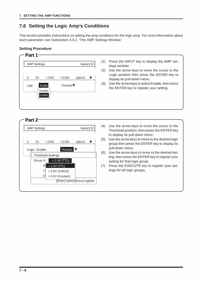
7 – 6
7. SETTING THE AMP FUNCTIONS
7.6 Setting the Logic Amp’s Conditions
This section provides instructions on setting the amp conditions for the logic amp. For more information abouteach parameter, see Subsection 4.4.2, “The AMP Settings Window.”
Setting Procedure
Part 1
Part 2(4) Use the arrow keys to move the cursor to the
Threshold position, then press the ENTER keyto display its pull-down menu.
(5) Use the arrow keys to move to the desired logicgroup then press the ENTER key to display itspull-down menu.
(6) Use the arrow keys to move to the desired set-ting, then press the ENTER key to register yoursetting for that logic group.
(7) Press the EXECUTE key to register your set-tings for all logic groups.
AMP Settings Input(1/2)
8: On + 0.000 + 20.000 kgf/cm2
Logic : Enable Threshold
Threshold Settings
Group A : + 1.4V (TTL)
B:
C:
D:
[Enter] select/[Exec] register
+ 1.4V (TTL)
+ 2.5V (CMOS)
+ 5.0V (Contact)
(1) Press the INPUT key to display the AMP set-tings window.
(2) Use the arrow keys to move the cursor to theLogic position then press the ENTER key todisplay its pull-down menu.
(3) Use the arrow keys to select Enable, then pressthe ENTER key to register your setting.
AMP Settings Input(1/2)
8: On + 0.000 + 20.000 kgf/cm2
Logic : Enable Threshold
Disable
Enable
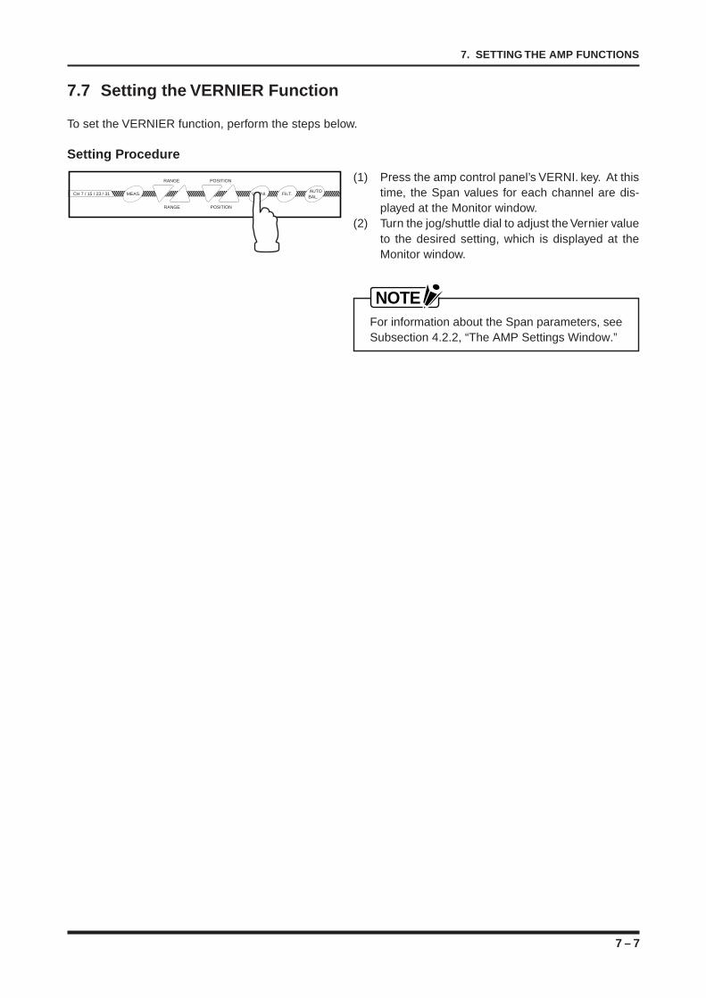
7 – 7
7. SETTING THE AMP FUNCTIONS
7.7 Setting the VERNIER Function
To set the VERNIER function, perform the steps below.
Setting Procedure
(1) Press the amp control panel’s VERNI. key. At thistime, the Span values for each channel are dis-played at the Monitor window.
(2) Turn the jog/shuttle dial to adjust the Vernier valueto the desired setting, which is displayed at theMonitor window.
NOTEFor information about the Span parameters, seeSubsection 4.2.2, “The AMP Settings Window.”
POSITIONRANGE
CH 7 / 15 / 23 / 31 MEAS. VERNI. FILT. AUTO
BAL.
POSITIONRANGE

7 – 8
7. SETTING THE AMP FUNCTIONS
8 – 1
8. RECORDING IN REALTIME
CHAPTER 8CHAPTER 8RECORDING IN REALTIME
This chapter describes how to set up your recorder toperform different types of realtime recording.
8.1 Overview of DIRECT Recording8.2 Enabling DIRECT Y-T Recording8.3 Enabling DIRECT X-Y Recording8.4 Enabling DIRECT Logging
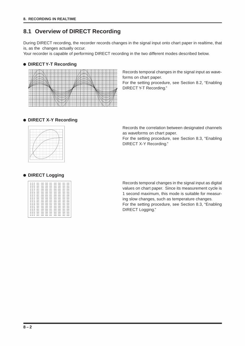
8 – 2
8. RECORDING IN REALTIME
8.1 Overview of DIRECT Recording
During DIRECT recording, the recorder records changes in the signal input onto chart paper in realtime, thatis, as the changes actually occur.Your recorder is capable of performing DIRECT recording in the two different modes described below.
DIRECT Y-T Recording
Records temporal changes in the signal input as wave-forms on chart paper.For the setting procedure, see Section 8.2, “EnablingDIRECT Y-T Recording.”
DIRECT X-Y Recording
Records the correlation between designated channelsas waveforms on chart paper.For the setting procedure, see Section 8.3, “EnablingDIRECT X-Y Recording.”
DIRECT Logging
Records temporal changes in the signal input as digitalvalues on chart paper. Since its measurement cycle is1 second maximum, this mode is suitable for measur-ing slow changes, such as temperature changes.For the setting procedure, see Section 8.3, “EnablingDIRECT Logging.”
01 : 01 : 22 –15.11 –15.44 –78.22 –15.11 –15.44 –78.22 –15.11 –15.44
01 : 01 : 21 –15.11 –15.44 –78.22 –15.11 –15.44 –78.22 –15.11 –15.44
01 : 01 : 20 –15.11 –15.44 –78.22 –15.11 –15.44 –78.22 –15.11 –15.44
01 : 01 : 19 –15.11 –15.44 –78.22 –15.11 –15.44 –78.22 –15.11 –15.44
01 : 01 : 18 –15.11 –15.44 –78.22 –15.11 –15.44 –78.22 –15.11 –15.44
01 : 01 : 17 –15.11 –15.44 –78.22 –15.11 –15.44 –78.22 –15.11 –15.44
01 : 01 : 16 –15.11 –15.44 –78.22 –15.11 –15.44 –78.22 –15.11 –15.44
01 : 01 : 15 –15.11 –15.44 –78.22 –15.11 –15.44 –78.22 –15.11 –15.44
01 : 01 : 14 –15.11 –15.44 –78.22 –15.11 –15.44 –78.22 –15.11 –15.44
01 : 01 : 13 –15.11 –15.44 –78.22 –15.11 –15.44 –78.22 –15.11 –15.44
01 : 01 : 12 –15.11 –15.44 –78.22 –15.11 –15.44 –78.22 –15.11 –15.44
01 : 01 : 11 –15.11 –15.44 –78.22 –15.11 –15.44 –78.22 –15.11 –15.44
01 : 01 : 10 –15.11 –15.44 –78.22 –15.11 –15.44 –78.22 –15.11 –15.44
01 : 01 : 09 –15.11 –15.44 –78.22 –15.11 –15.44 –78.22 –15.11 –15.44
01 : 01 : 08 –15.11 –15.44 –78.22 –15.11 –15.44 –78.22 –15.11 –15.44
01 : 01 : 07 –15.11 –15.44 –78.22 –15.11 –15.44 –78.22 –15.11 –15.44
01 : 01 : 06 –15.11 –15.44 –78.22 –15.11 –15.44 –78.22 –15.11 –15.44
01 : 01 : 05 –15.11 –15.44 –78.22 –15.11 –15.44 –78.22 –15.11 –15.44
01 : 01 : 04 –15.11 –15.44 –78.22 –15.11 –15.44 –78.22 –15.11 –15.44
01 : 01 : 03 –15.11 –15.44 –78.22 –15.11 –15.44 –78.22 –15.11 –15.44
01 : 01 : 02 –15.11 –15.44 –78.22 –15.11 –15.44 –78.22 –15.11 –15.44
01 : 01 : 01 –15.11 –15.44 –78.22 –15.11 –15.44 –78.22 –15.11 –15.44
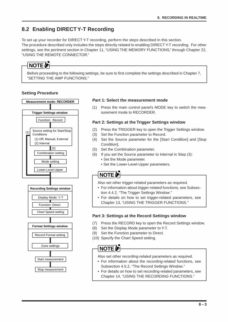
8 – 3
8. RECORDING IN REALTIME
8.2 Enabling DIRECT Y-T Recording
To set up your recorder for DIRECT Y-T recording, perform the steps described in this section.The procedure described only includes the steps directly related to enabling DIRECT Y-T recording. For othersettings, see the pertinent section in Chapter 11, “USING THE MEMORY FUNCTIONS,” through Chapter 22,“USING THE REMOTE CONNECTOR.”
NOTEBefore proceeding to the following settings, be sure to first complete the settings described in Chapter 7,“SETTING THE AMP FUNCTIONS.”
Setting Procedure
Part 1: Select the measurement mode
(1) Press the main control panel’s MODE key to switch the mea-surement mode to RECORDER.
Part 2: Settings at the Trigger Settings window
(2) Press the TRIGGER key to open the Trigger Settings window.(3) Set the Function parameter to Record.(4) Set the Source parameter for the [Start Condition] and [Stop
Condition].(5) Set the Combination parameter.(6) If you set the Source parameter to Internal in Step (3):
• Set the Mode parameter.• Set the Lower-Level-Upper parameters.
NOTEAlso set other trigger-related parameters as required.• For information about trigger-related functions, see Subsec-
tion 4.4.2, “The Trigger Settings Window.”• For details on how to set trigger-related parameters, see
Chapter 13, “USING THE TRIGGER FUNCTIONS.”
Part 3: Settings at the Record Settings window
(7) Press the RECORD key to open the Record Settings window.(8) Set the Display Mode parameter to Y-T.(9) Set the Function parameter to Direct.(10) Specify the Chart Speed setting.
NOTEAlso set other recording-related parameters as required.• For information about the recording-related functions, see
Subsection 4.5.2, “The Record Settings Window.”• For details on how to set recording-related parameters, see
Chapter 14, “USING THE RECORDING FUNCTIONS.”
Measurement mode: RECORDER
Trigger Settings window
Function: Record
Lower-Level-Upper
Mode setting
Combination setting
Recording Settings window
Display Mode: Y-T
Chart Speed setting
Format Settings window
Record Format setting
Zone settings
Start measurement
Stop measurement
(1)
(2)
Source setting for Start/Stop Conditions
(1) Off, Manual, External (2) Internal
Function: Direct
8 – 4
8. RECORDING IN REALTIME
Part 4: Settings at the Format Settings window
(11) Press the RECORD key to open the Format Settings window.(12) Set the Record Format parameter.(13) Assign the Channel Nos. to Zones.
NOTEAlso perform other format-related settings as required.• For information about format-related functions, see Sub-
section 4.5.3, “The Format Settings Window.”• For details on how to set format-related parameters, see
Chapter 14, “USING THE RECORDING FUNCTIONS.”
Part 5: Start measurement
(14) Press the CLOSE key to close the currently opened window.(15) Press the PRINTER key (if you wish to record onto chart pa-
per).(16) Press the START key.(17) Press the TRIGGER key (if the [Start Condition] Source set-
ting at the Trigger Settings window is Manual).
Part 6: Stop measurement
(18) Press the TRIGGER key (if the [Stop Condition] Source settingat the Trigger Settings window is Manual).
(19) Press the STOP key.
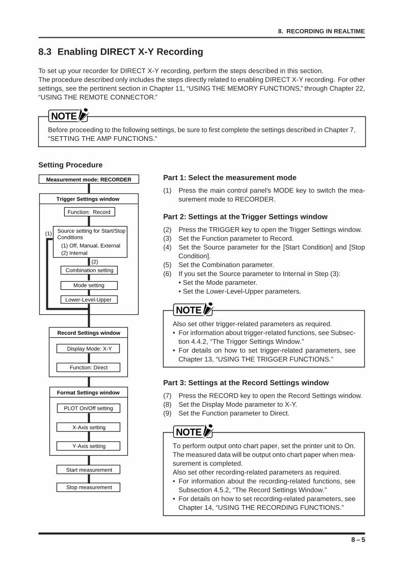
8 – 5
8. RECORDING IN REALTIME
8.3 Enabling DIRECT X-Y Recording
To set up your recorder for DIRECT X-Y recording, perform the steps described in this section.The procedure described only includes the steps directly related to enabling DIRECT X-Y recording. For othersettings, see the pertinent section in Chapter 11, “USING THE MEMORY FUNCTIONS,” through Chapter 22,“USING THE REMOTE CONNECTOR.”
NOTEBefore proceeding to the following settings, be sure to first complete the settings described in Chapter 7,“SETTING THE AMP FUNCTIONS.”
Setting Procedure
Part 1: Select the measurement mode
(1) Press the main control panel’s MODE key to switch the mea-surement mode to RECORDER.
Part 2: Settings at the Trigger Settings window
(2) Press the TRIGGER key to open the Trigger Settings window.(3) Set the Function parameter to Record.(4) Set the Source parameter for the [Start Condition] and [Stop
Condition].(5) Set the Combination parameter.(6) If you set the Source parameter to Internal in Step (3):
• Set the Mode parameter.• Set the Lower-Level-Upper parameters.
NOTEAlso set other trigger-related parameters as required.• For information about trigger-related functions, see Subsec-
tion 4.4.2, “The Trigger Settings Window.”• For details on how to set trigger-related parameters, see
Chapter 13, “USING THE TRIGGER FUNCTIONS.”
Part 3: Settings at the Record Settings window
(7) Press the RECORD key to open the Record Settings window.(8) Set the Display Mode parameter to X-Y.(9) Set the Function parameter to Direct.
NOTETo perform output onto chart paper, set the printer unit to On.The measured data will be output onto chart paper when mea-surement is completed.Also set other recording-related parameters as required.• For information about the recording-related functions, see
Subsection 4.5.2, “The Record Settings Window.”• For details on how to set recording-related parameters, see
Chapter 14, “USING THE RECORDING FUNCTIONS.”
Measurement mode: RECORDER
Trigger Settings window
Function: Record
Lower-Level-Upper
Mode setting
Combination setting
Record Settings window
Display Mode: X-Y
Function: Direct
Format Settings window
PLOT On/Off setting
X-Axis setting
Y-Axis setting
Start measurement
Stop measurement
(1)
(2)
Source setting for Start/Stop Conditions
(1) Off, Manual, External (2) Internal
8 – 6
8. RECORDING IN REALTIME
Part 4: Settings at the Format Settings window
(10) Press the RECORD key to open the Format Settings window.(11) Select the On/Off status of the PLOT parameter.(12) Set the X-Axis parameter.(13) Set the Y-Axis parameter.
NOTEAlso perform other format-related settings as required.• For information about format-related functions, see Subsec-
tion 4.5.3, “The Format Settings Window.”• For details on how to set format-related parameters, see
Chapter 14, “USING THE RECORDING FUNCTIONS.”
Part 5: Start measurement
(14) Press the CLOSE key to close the currently opened window.(15) Press the PRINTER key (if you wish to record onto chart pa-
per).(16) Press the START key.(17) Press the TRIGGER key (if the [Start Condition] Source setting
at the Trigger Settings window is Manual).
Part 6: Stop measurement
(18) Press the TRIGGER key (if the [Stop Condition] Source settingat the Trigger Settings window is Manual).
(19) Press the STOP key.
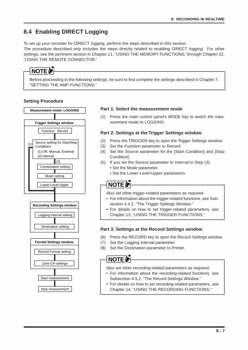
8 – 7
8. RECORDING IN REALTIME
8.4 Enabling DIRECT Logging
To set up your recorder for DIRECT logging, perform the steps described in this section.The procedure described only includes the steps directly related to enabling DIRECT logging. For othersettings, see the pertinent section in Chapter 11, “USING THE MEMORY FUNCTIONS,” through Chapter 22,“USING THE REMOTE CONNECTOR.”
NOTEBefore proceeding to the following settings, be sure to first complete the settings described in Chapter 7,“SETTING THE AMP FUNCTIONS.”
Setting Procedure
Part 1: Select the measurement mode
(1) Press the main control panel’s MODE key to switch the mea-surement mode to LOGGING.
Part 2: Settings at the Trigger Settings window
(2) Press the TRIGGER key to open the Trigger Settings window.(3) Set the Function parameter to Record.(4) Set the Source parameter for the [Start Condition] and [Stop
Condition].(5) If you set the Source parameter to Internal in Step (3):
• Set the Mode parameter.• Set the Lower-Level-Upper parameters.
NOTEAlso set other trigger-related parameters as required.• For information about the trigger-related functions, see Sub-
section 4.4.2, “The Trigger Settings Window.”• For details on how to set trigger-related parameters, see
Chapter 13, “USING THE TRIGGER FUNCTIONS.”
Part 3: Settings at the Record Settings window
(6) Press the RECORD key to open the Record Settings window.(7) Set the Logging Interval parameter.(8) Set the Destination parameter to Printer.
NOTEAlso set other recording-related parameters as required.• For information about the recording-related functions, see
Subsection 4.5.2, “The Record Settings Window.”• For details on how to set recording-related parameters, see
Chapter 14, “USING THE RECORDING FUNCTIONS.”
Measurement mode: LOGGING
Trigger Settings window
Function: Record
Lower-Level-Upper
Mode setting
Combination setting
Recording Settings window
Logging Interval setting
Destination setting
Format Settings window
Record Format setting
Zone CH settings
Start measurement
Stop measurement
(1)
(2)
Source setting for Start/Stop Conditions
(1) Off, Manual, External (2) Internal
8 – 8
8. RECORDING IN REALTIME
Part 4: Settings at the Format Settings window
(9) Press the RECORD key to open the Format Settings window.(10) Set the Format parameter.(11) Set the Zone and CH parameters.
NOTEAlso perform other format-related settings as required.• For information about format-related functions, see Subsec-
tion 4.5.3, “The Format Settings Window.”• For details on how to set format-related parameters, see
Chapter 14, “USING THE RECORDING FUNCTIONS.”
Part 5: Start measurement
(12) Press the CLOSE key to close the currently opened window.(13) Press the PRINTER key (if you wish to record onto chart pa-
per).(14) Press the START key.(15) Press the TRIGGER key (if the [Start Condition] Source setting
at the Trigger Settings window is Manual).
Part 6: Stop measurement
(16) Press the TRIGGER key (if the [Stop Condition] Source settingat the Trigger Settings window is Manual).
(17) Press the STOP key.
9 – 1
9. SAVING DATA IN REALTIME
SAVING DATA IN REALTIME
This chapter describes how to set up your recorder tosimultaneously record and save data in realtime.
9.1 Overview of DIRECT SAVE Operations9.2 Enabling DIRECT Y-T SAVE Operations9.3 Enabling DIRECT X-Y SAVE Operations9.4 Enabling DIRECT LOGGING SAVE Operations
CHAPTER 9CHAPTER 9
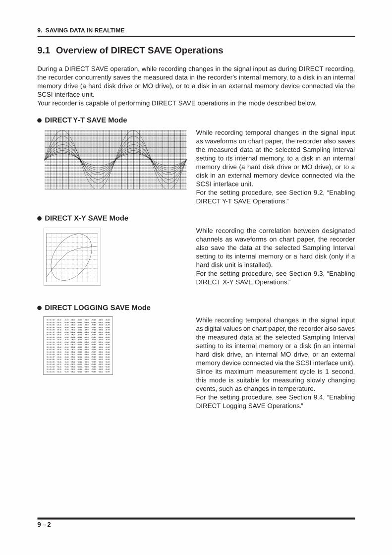
9 – 2
9. SAVING DATA IN REALTIME
9.1 Overview of DIRECT SAVE Operations
During a DIRECT SAVE operation, while recording changes in the signal input as during DIRECT recording,the recorder concurrently saves the measured data in the recorder’s internal memory, to a disk in an internalmemory drive (a hard disk drive or MO drive), or to a disk in an external memory device connected via theSCSI interface unit.Your recorder is capable of performing DIRECT SAVE operations in the mode described below.
DIRECT Y-T SAVE Mode
While recording temporal changes in the signal inputas waveforms on chart paper, the recorder also savesthe measured data at the selected Sampling Intervalsetting to its internal memory, to a disk in an internalmemory drive (a hard disk drive or MO drive), or to adisk in an external memory device connected via theSCSI interface unit.For the setting procedure, see Section 9.2, “EnablingDIRECT Y-T SAVE Operations.”
DIRECT X-Y SAVE Mode
While recording the correlation between designatedchannels as waveforms on chart paper, the recorderalso save the data at the selected Sampling Intervalsetting to its internal memory or a hard disk (only if ahard disk unit is installed).For the setting procedure, see Section 9.3, “EnablingDIRECT X-Y SAVE Operations.”
DIRECT LOGGING SAVE Mode
While recording temporal changes in the signal inputas digital values on chart paper, the recorder also savesthe measured data at the selected Sampling Intervalsetting to its internal memory or a disk (in an internalhard disk drive, an internal MO drive, or an externalmemory device connected via the SCSI interface unit).Since its maximum measurement cycle is 1 second,this mode is suitable for measuring slowly changingevents, such as changes in temperature.For the setting procedure, see Section 9.4, “EnablingDIRECT Logging SAVE Operations.”
01 : 01 : 22 –15.11 –15.44 –78.22 –15.11 –15.44 –78.22 –15.11 –15.44
01 : 01 : 21 –15.11 –15.44 –78.22 –15.11 –15.44 –78.22 –15.11 –15.44
01 : 01 : 20 –15.11 –15.44 –78.22 –15.11 –15.44 –78.22 –15.11 –15.44
01 : 01 : 19 –15.11 –15.44 –78.22 –15.11 –15.44 –78.22 –15.11 –15.44
01 : 01 : 18 –15.11 –15.44 –78.22 –15.11 –15.44 –78.22 –15.11 –15.44
01 : 01 : 17 –15.11 –15.44 –78.22 –15.11 –15.44 –78.22 –15.11 –15.44
01 : 01 : 16 –15.11 –15.44 –78.22 –15.11 –15.44 –78.22 –15.11 –15.44
01 : 01 : 15 –15.11 –15.44 –78.22 –15.11 –15.44 –78.22 –15.11 –15.44
01 : 01 : 14 –15.11 –15.44 –78.22 –15.11 –15.44 –78.22 –15.11 –15.44
01 : 01 : 13 –15.11 –15.44 –78.22 –15.11 –15.44 –78.22 –15.11 –15.44
01 : 01 : 12 –15.11 –15.44 –78.22 –15.11 –15.44 –78.22 –15.11 –15.44
01 : 01 : 11 –15.11 –15.44 –78.22 –15.11 –15.44 –78.22 –15.11 –15.44
01 : 01 : 10 –15.11 –15.44 –78.22 –15.11 –15.44 –78.22 –15.11 –15.44
01 : 01 : 09 –15.11 –15.44 –78.22 –15.11 –15.44 –78.22 –15.11 –15.44
01 : 01 : 08 –15.11 –15.44 –78.22 –15.11 –15.44 –78.22 –15.11 –15.44
01 : 01 : 07 –15.11 –15.44 –78.22 –15.11 –15.44 –78.22 –15.11 –15.44
01 : 01 : 06 –15.11 –15.44 –78.22 –15.11 –15.44 –78.22 –15.11 –15.44
01 : 01 : 05 –15.11 –15.44 –78.22 –15.11 –15.44 –78.22 –15.11 –15.44
01 : 01 : 04 –15.11 –15.44 –78.22 –15.11 –15.44 –78.22 –15.11 –15.44
01 : 01 : 03 –15.11 –15.44 –78.22 –15.11 –15.44 –78.22 –15.11 –15.44
01 : 01 : 02 –15.11 –15.44 –78.22 –15.11 –15.44 –78.22 –15.11 –15.44
01 : 01 : 01 –15.11 –15.44 –78.22 –15.11 –15.44 –78.22 –15.11 –15.44
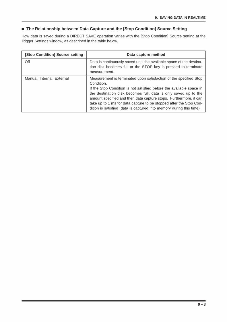
9 – 3
9. SAVING DATA IN REALTIME
The Relationship between Data Capture and the [Stop Condition] Source Setting
How data is saved during a DIRECT SAVE operation varies with the [Stop Condition] Source setting at theTrigger Settings window, as described in the table below.
[Stop Condition] Source setting Data capture method
Off Data is continuously saved until the available space of the destina-tion disk becomes full or the STOP key is pressed to terminatemeasurement.
Manual, Internal, External Measurement is terminated upon satisfaction of the specified StopCondition.If the Stop Condition is not satisfied before the available space inthe destination disk becomes full, data is only saved up to theamount specified and then data capture stops. Furthermore, it cantake up to 1 ms for data capture to be stopped after the Stop Con-dition is satisfied (data is captured into memory during this time).
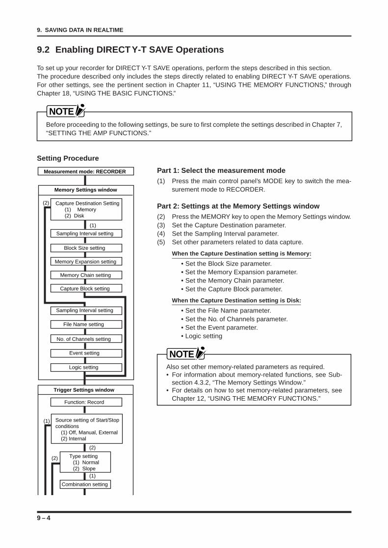
9 – 4
9. SAVING DATA IN REALTIME
9.2 Enabling DIRECT Y-T SAVE Operations
To set up your recorder for DIRECT Y-T SAVE operations, perform the steps described in this section.The procedure described only includes the steps directly related to enabling DIRECT Y-T SAVE operations.For other settings, see the pertinent section in Chapter 11, “USING THE MEMORY FUNCTIONS,” throughChapter 18, “USING THE BASIC FUNCTIONS.”
NOTEBefore proceeding to the following settings, be sure to first complete the settings described in Chapter 7,“SETTING THE AMP FUNCTIONS.”
Setting Procedure
Part 1: Select the measurement mode(1) Press the main control panel’s MODE key to switch the mea-
surement mode to RECORDER.
Part 2: Settings at the Memory Settings window(2) Press the MEMORY key to open the Memory Settings window.(3) Set the Capture Destination parameter.(4) Set the Sampling Interval parameter.(5) Set other parameters related to data capture.
When the Capture Destination setting is Memory:
• Set the Block Size parameter.• Set the Memory Expansion parameter.• Set the Memory Chain parameter.• Set the Capture Block parameter.
When the Capture Destination setting is Disk:
• Set the File Name parameter.• Set the No. of Channels parameter.• Set the Event parameter.• Logic setting
NOTEAlso set other memory-related parameters as required.• For information about memory-related functions, see Sub-
section 4.3.2, “The Memory Settings Window.”• For details on how to set memory-related parameters, see
Chapter 12, “USING THE MEMORY FUNCTIONS.”
Measurement mode: RECORDER
Trigger Settings window
Function: Record
Source setting of Start/Stop conditions
(1) Off, Manual, External (2) Internal
Combination setting
(2)
(1)
(1)
Type setting(1) Normal (2) Slope
(2)
Memory Settings window
Memory Expansion setting
Block Size setting
Sampling Interval setting
Memory Chain setting
Capture Block setting
Capture Destination Setting(1) Memory (2) Disk
Sampling Interval setting
File Name setting
No. of Channels setting
Event setting
Logic setting
(2)
(1)
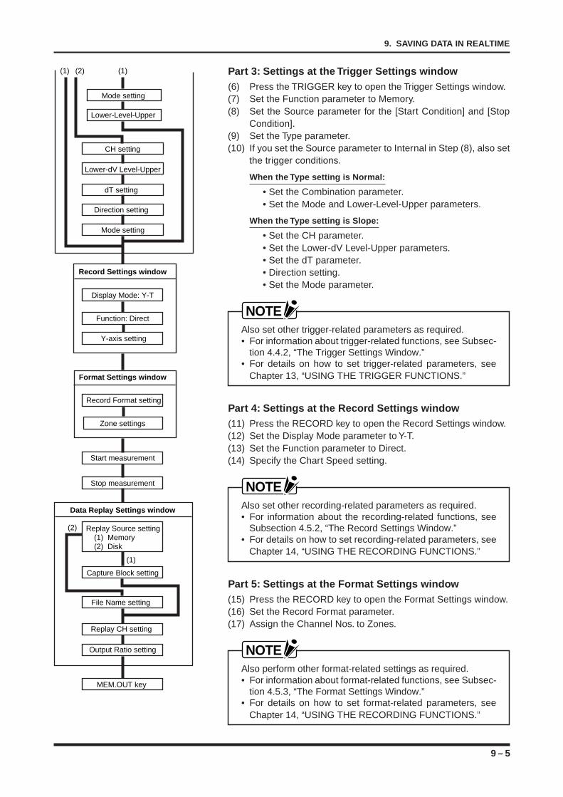
9 – 5
9. SAVING DATA IN REALTIME
Part 3: Settings at the Trigger Settings window(6) Press the TRIGGER key to open the Trigger Settings window.(7) Set the Function parameter to Memory.(8) Set the Source parameter for the [Start Condition] and [Stop
Condition].(9) Set the Type parameter.(10) If you set the Source parameter to Internal in Step (8), also set
the trigger conditions.
When the Type setting is Normal:
• Set the Combination parameter.• Set the Mode and Lower-Level-Upper parameters.
When the Type setting is Slope:
• Set the CH parameter.• Set the Lower-dV Level-Upper parameters.• Set the dT parameter.• Direction setting.• Set the Mode parameter.
NOTEAlso set other trigger-related parameters as required.• For information about trigger-related functions, see Subsec-
tion 4.4.2, “The Trigger Settings Window.”• For details on how to set trigger-related parameters, see
Chapter 13, “USING THE TRIGGER FUNCTIONS.”
Part 4: Settings at the Record Settings window(11) Press the RECORD key to open the Record Settings window.(12) Set the Display Mode parameter to Y-T.(13) Set the Function parameter to Direct.(14) Specify the Chart Speed setting.
NOTEAlso set other recording-related parameters as required.• For information about the recording-related functions, see
Subsection 4.5.2, “The Record Settings Window.”• For details on how to set recording-related parameters, see
Chapter 14, “USING THE RECORDING FUNCTIONS.”
Part 5: Settings at the Format Settings window(15) Press the RECORD key to open the Format Settings window.(16) Set the Record Format parameter.(17) Assign the Channel Nos. to Zones.
NOTEAlso perform other format-related settings as required.• For information about format-related functions, see Subsec-
tion 4.5.3, “The Format Settings Window.”• For details on how to set format-related parameters, see
Chapter 14, “USING THE RECORDING FUNCTIONS.”
Data Replay Settings window
Capture Block setting
Replay Source setting(1) Memory (2) Disk
File Name setting
Replay CH setting
Output Ratio setting
MEM.OUT key
Record Settings window
Function: Direct
Record Format setting
Format Settings window
Zone settings
Y-axis setting
Display Mode: Y-T
Start measurement
Stop measurement
Lower-Level-Upper
Mode setting
CH setting
Lower-dV Level-Upper
dT setting
Direction setting
Mode setting
(1) (2) (1)
(2)
(1)
9 – 6
9. SAVING DATA IN REALTIME
Part 6: Start measurement(18) Press the CLOSE key to close the currently opened window.(19) Press the PRINTER key (if you wish to record onto chart pa-
per).(20) Press the START key.(21) Press the TRIGGER key (if the [Start Condition] Source setting
at the Trigger Settings window is Manual).
Part 7: Stop measurement(22) Press the TRIGGER key (if the [Stop Condition] Source setting
at the Trigger Settings window is Manual).(23) Press the STOP key.
Part 8: Set the Replay Conditions for the Captured Data(24) Press the MEMORY key to open the Data Replay Settings
window.(25) Set the Replay Source parameter.(26) Set the Capture Block or File Name parameter.
When the Replay Source setting is Memory:
• Set the Capture Block parameter.
When the Replay Source setting is Disk:
• Set the File Name parameter.
(27) Set the Replay CH parameter.(28) Set the Output Ratio parameter.
Part 9: Replay the Captured Data(29) Press the main control panel’s MEM.OUT key.
NOTE• To concurrently record the replay data onto chart paper,
press the EXECUTE key to open the EXECUTE menu andset a Printer Output operation. For instructions, see Section12.6, “Outputting Data Being Replayed onto Chart Paper.”
• During the replay of captured data, the recorder’s operatingmode switches automatically to Replay mode. In Replaymode, you cannot change any of the recorder’s settings.To change a setting, press the main control panel’s MODE/EVENT key to exit Replay mode and then proceed to thedesired window.
• If the Replay Source is Disk, do not attempt any disk opera-tions while in Replay mode. The disk may be damaged ifyou do so.
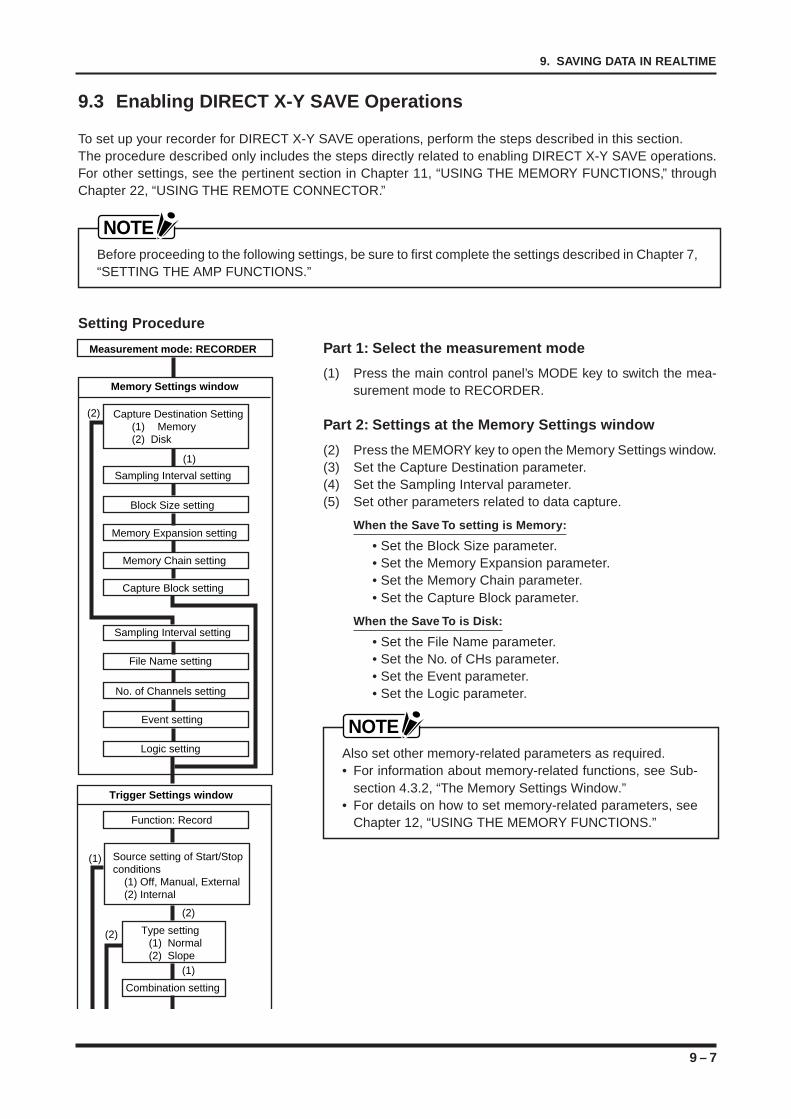
9 – 7
9. SAVING DATA IN REALTIME
9.3 Enabling DIRECT X-Y SAVE Operations
To set up your recorder for DIRECT X-Y SAVE operations, perform the steps described in this section.The procedure described only includes the steps directly related to enabling DIRECT X-Y SAVE operations.For other settings, see the pertinent section in Chapter 11, “USING THE MEMORY FUNCTIONS,” throughChapter 22, “USING THE REMOTE CONNECTOR.”
NOTEBefore proceeding to the following settings, be sure to first complete the settings described in Chapter 7,“SETTING THE AMP FUNCTIONS.”
Setting Procedure
Part 1: Select the measurement mode
(1) Press the main control panel’s MODE key to switch the mea-surement mode to RECORDER.
Part 2: Settings at the Memory Settings window
(2) Press the MEMORY key to open the Memory Settings window.(3) Set the Capture Destination parameter.(4) Set the Sampling Interval parameter.(5) Set other parameters related to data capture.
When the Save To setting is Memory:
• Set the Block Size parameter.• Set the Memory Expansion parameter.• Set the Memory Chain parameter.• Set the Capture Block parameter.
When the Save To is Disk:
• Set the File Name parameter.• Set the No. of CHs parameter.• Set the Event parameter.• Set the Logic parameter.
NOTEAlso set other memory-related parameters as required.• For information about memory-related functions, see Sub-
section 4.3.2, “The Memory Settings Window.”• For details on how to set memory-related parameters, see
Chapter 12, “USING THE MEMORY FUNCTIONS.”
Measurement mode: RECORDER
Trigger Settings window
Function: Record
Source setting of Start/Stop conditions
(1) Off, Manual, External (2) Internal
Combination setting
(2)
(1)
(1)
Type setting(1) Normal (2) Slope
(2)
Memory Settings window
Memory Expansion setting
Block Size setting
Sampling Interval setting
Memory Chain setting
Capture Block setting
Capture Destination Setting(1) Memory (2) Disk
Sampling Interval setting
File Name setting
No. of Channels setting
Event setting
Logic setting
(2)
(1)
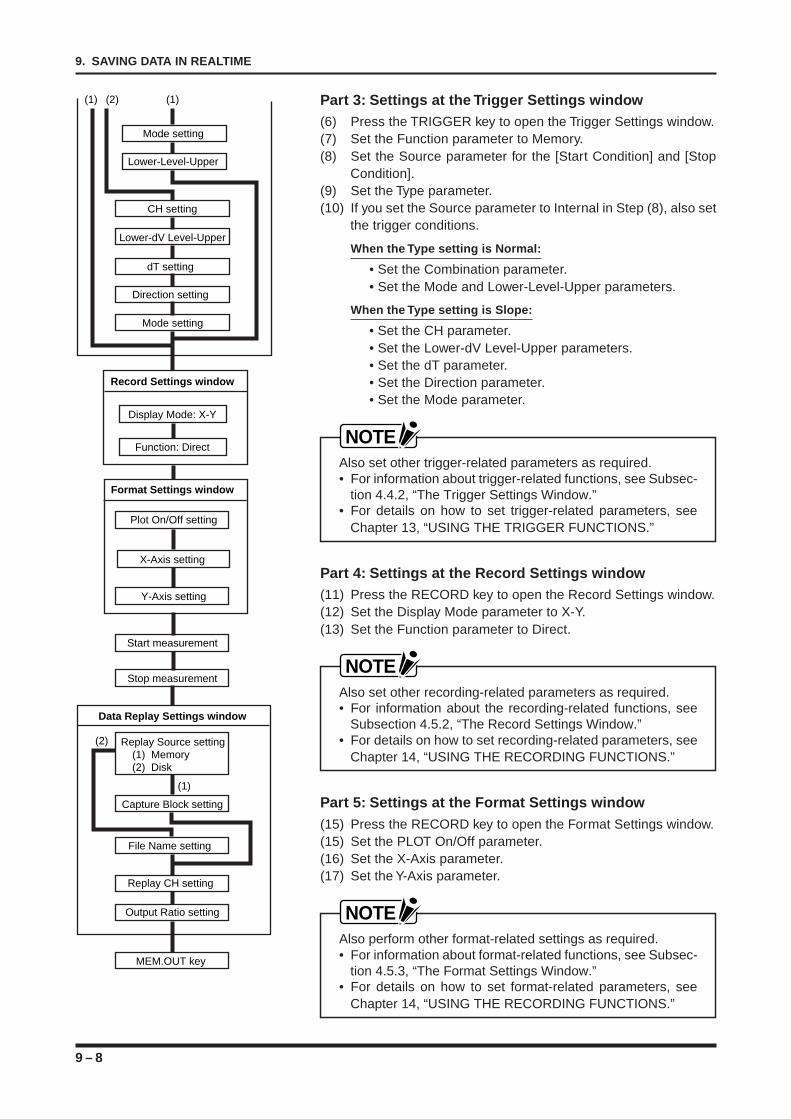
9 – 8
9. SAVING DATA IN REALTIME
Data Replay Settings window
Capture Block setting
Replay Source setting(1) Memory (2) Disk
File Name setting
Replay CH setting
Output Ratio setting
MEM.OUT key
Record Settings window
Function: Direct
Plot On/Off setting
Format Settings window
X-Axis setting
Y-Axis setting
Display Mode: X-Y
Start measurement
Stop measurement
Lower-Level-Upper
Mode setting
CH setting
Lower-dV Level-Upper
dT setting
Direction setting
Mode setting
(1) (2) (1)
(2)
(1)
Part 3: Settings at the Trigger Settings window(6) Press the TRIGGER key to open the Trigger Settings window.(7) Set the Function parameter to Memory.(8) Set the Source parameter for the [Start Condition] and [Stop
Condition].(9) Set the Type parameter.(10) If you set the Source parameter to Internal in Step (8), also set
the trigger conditions.
When the Type setting is Normal:
• Set the Combination parameter.• Set the Mode and Lower-Level-Upper parameters.
When the Type setting is Slope:
• Set the CH parameter.• Set the Lower-dV Level-Upper parameters.• Set the dT parameter.• Set the Direction parameter.• Set the Mode parameter.
NOTEAlso set other trigger-related parameters as required.• For information about trigger-related functions, see Subsec-
tion 4.4.2, “The Trigger Settings Window.”• For details on how to set trigger-related parameters, see
Chapter 13, “USING THE TRIGGER FUNCTIONS.”
Part 4: Settings at the Record Settings window(11) Press the RECORD key to open the Record Settings window.(12) Set the Display Mode parameter to X-Y.(13) Set the Function parameter to Direct.
NOTEAlso set other recording-related parameters as required.• For information about the recording-related functions, see
Subsection 4.5.2, “The Record Settings Window.”• For details on how to set recording-related parameters, see
Chapter 14, “USING THE RECORDING FUNCTIONS.”
Part 5: Settings at the Format Settings window(15) Press the RECORD key to open the Format Settings window.(15) Set the PLOT On/Off parameter.(16) Set the X-Axis parameter.(17) Set the Y-Axis parameter.
NOTEAlso perform other format-related settings as required.• For information about format-related functions, see Subsec-
tion 4.5.3, “The Format Settings Window.”• For details on how to set format-related parameters, see
Chapter 14, “USING THE RECORDING FUNCTIONS.”
9 – 9
9. SAVING DATA IN REALTIME
Part 6: Start measurement(18) Press the CLOSE key to close the currently opened window.(19) Press the PRINTER key (if you wish to record onto chart pa-
per).(20) Press the START key.(21) Press the TRIGGER key (if the [Start Condition] Source setting
at the Trigger Settings window is Manual).
Part 7: Stop measurement(22) Press the TRIGGER key (if the [Stop Condition] Source setting
at the Trigger Settings window is Manual).(23) Press the STOP key.
Part 8: Set the Replay Conditions for the Captured Data
(24) Press the MEMORY key to open the Data Replay Settings win-dow.
(25) Set the Replay Source parameter.(26) Set the Capture Block or File Name parameter.
When the Replay Source setting is Memory:
• Set the Capture Block parameter.
When the Replay Source setting is Disk:
• Set the File Name parameter.
(27) Set the Replay CH parameter.(28) Set the Output Ratio parameter.
Part 9: Replay the Captured Data(29) Press the main control panel’s MEM.OUT key.
NOTETo concurrently record the replay data onto chart paper, pressthe EXECUTE key to open the Execute menu and set aPrinter Output operation. For instructions, see Section 12.6,“Outputting Data Being Replayed onto Chart Paper.”• When captured data is replayed, the operating mode auto-
matically switches to Replay mode. In Replay mode, therecorder’s settings cannot be changed. To change a set-ting, exit the Replay mode by pressing the main controlpanel’s MODE key.
• Never remove or exchange a disk during Replay Modewhen the Replay Source setting is Disk, or you may damagethe disk’s contents.
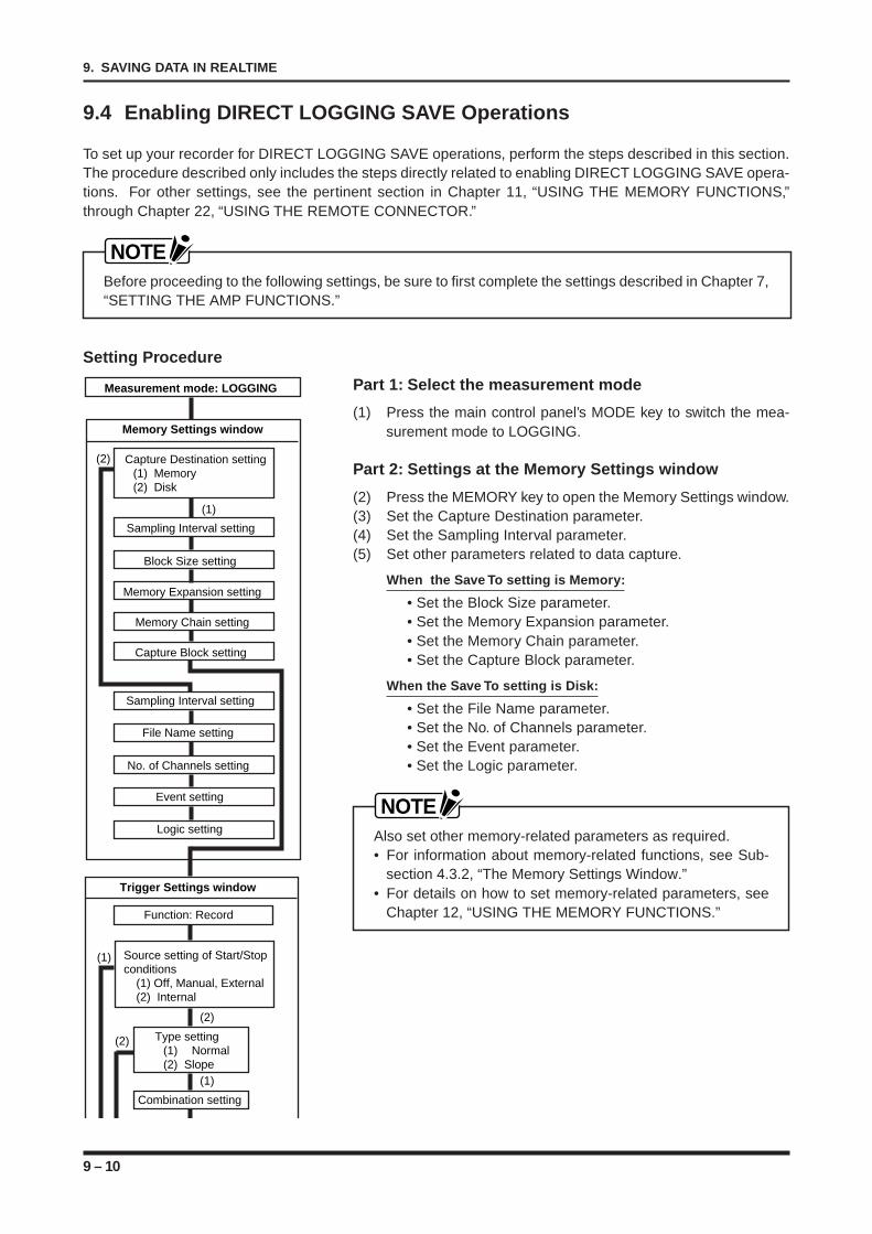
9 – 10
9. SAVING DATA IN REALTIME
9.4 Enabling DIRECT LOGGING SAVE Operations
To set up your recorder for DIRECT LOGGING SAVE operations, perform the steps described in this section.The procedure described only includes the steps directly related to enabling DIRECT LOGGING SAVE opera-tions. For other settings, see the pertinent section in Chapter 11, “USING THE MEMORY FUNCTIONS,”through Chapter 22, “USING THE REMOTE CONNECTOR.”
NOTEBefore proceeding to the following settings, be sure to first complete the settings described in Chapter 7,“SETTING THE AMP FUNCTIONS.”
Setting Procedure
Part 1: Select the measurement mode
(1) Press the main control panel’s MODE key to switch the mea-surement mode to LOGGING.
Part 2: Settings at the Memory Settings window
(2) Press the MEMORY key to open the Memory Settings window.(3) Set the Capture Destination parameter.(4) Set the Sampling Interval parameter.(5) Set other parameters related to data capture.
When the Save To setting is Memory:
• Set the Block Size parameter.• Set the Memory Expansion parameter.• Set the Memory Chain parameter.• Set the Capture Block parameter.
When the Save To setting is Disk:
• Set the File Name parameter.• Set the No. of Channels parameter.• Set the Event parameter.• Set the Logic parameter.
NOTEAlso set other memory-related parameters as required.• For information about memory-related functions, see Sub-
section 4.3.2, “The Memory Settings Window.”• For details on how to set memory-related parameters, see
Chapter 12, “USING THE MEMORY FUNCTIONS.”
Measurement mode: LOGGING
Memory Settings window
Memory Expansion setting
Block Size setting
Sampling Interval setting
Memory Chain setting
Capture Block setting
Capture Destination setting(1) Memory (2) Disk
Sampling Interval setting
File Name setting
No. of Channels setting
Event setting
(2)
(1)
Trigger Settings window
Function: Record
Source setting of Start/Stop conditions
(1) Off, Manual, External (2) Internal
Combination setting
(2)
(1)
(1)
Type setting(1) Normal (2) Slope
(2)
Logic setting
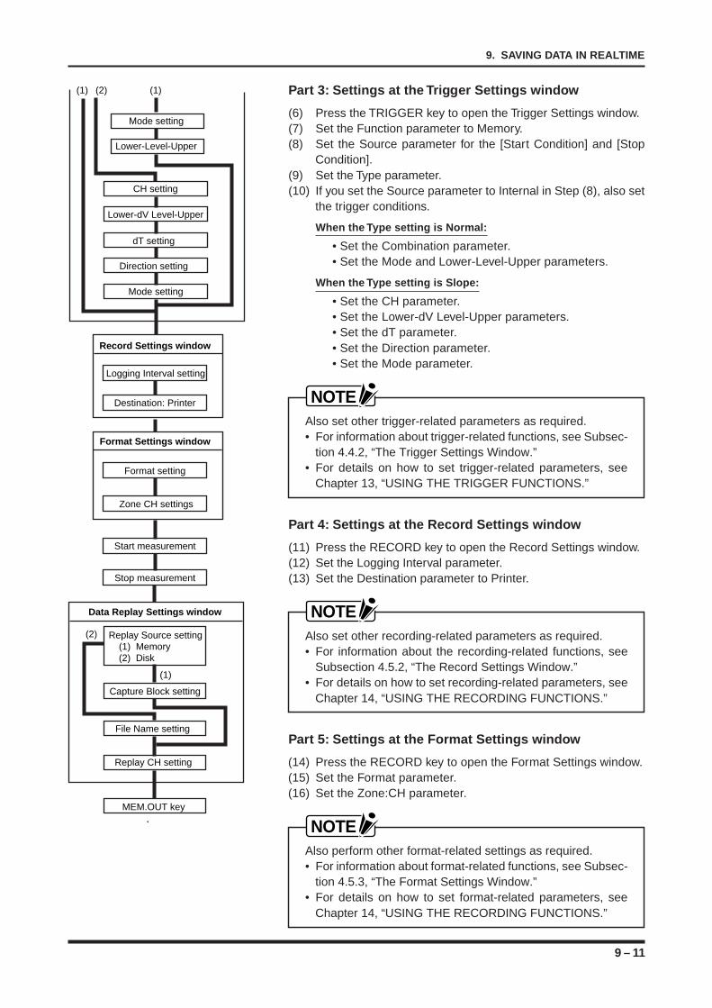
9 – 11
9. SAVING DATA IN REALTIME
Part 3: Settings at the Trigger Settings window
(6) Press the TRIGGER key to open the Trigger Settings window.(7) Set the Function parameter to Memory.(8) Set the Source parameter for the [Start Condition] and [Stop
Condition].(9) Set the Type parameter.(10) If you set the Source parameter to Internal in Step (8), also set
the trigger conditions.
When the Type setting is Normal:
• Set the Combination parameter.• Set the Mode and Lower-Level-Upper parameters.
When the Type setting is Slope:
• Set the CH parameter.• Set the Lower-dV Level-Upper parameters.• Set the dT parameter.• Set the Direction parameter.• Set the Mode parameter.
NOTEAlso set other trigger-related parameters as required.• For information about trigger-related functions, see Subsec-
tion 4.4.2, “The Trigger Settings Window.”• For details on how to set trigger-related parameters, see
Chapter 13, “USING THE TRIGGER FUNCTIONS.”
Part 4: Settings at the Record Settings window
(11) Press the RECORD key to open the Record Settings window.(12) Set the Logging Interval parameter.(13) Set the Destination parameter to Printer.
NOTEAlso set other recording-related parameters as required.• For information about the recording-related functions, see
Subsection 4.5.2, “The Record Settings Window.”• For details on how to set recording-related parameters, see
Chapter 14, “USING THE RECORDING FUNCTIONS.”
Part 5: Settings at the Format Settings window
(14) Press the RECORD key to open the Format Settings window.(15) Set the Format parameter.(16) Set the Zone:CH parameter.
NOTEAlso perform other format-related settings as required.• For information about format-related functions, see Subsec-
tion 4.5.3, “The Format Settings Window.”• For details on how to set format-related parameters, see
Chapter 14, “USING THE RECORDING FUNCTIONS.”
Data Replay Settings window
Capture Block setting
Replay Source setting(1) Memory (2) Disk
File Name setting
Replay CH setting
MEM.OUT key
Record Settings window
Destination: Printer
Format Settings window
Format setting
Zone CH settings
Logging Interval setting
Start measurement
Stop measurement
(2)
(1)
Lower-Level-Upper
Mode setting
CH setting
Lower-dV Level-Upper
dT setting
Direction setting
Mode setting
(1) (2) (1)
9 – 12
9. SAVING DATA IN REALTIME
Part 6: Start measurement
(17) Press the CLOSE key to close the currently opened window.(18) Press the PRINTER key (if you wish to record onto chart pa-
per).(19) Press the START key.(20) Press the TRIGGER key (if the [Start Condition] Source setting
at the Trigger Settings window is Manual).
Part 7: Stop measurement
(21) Press the TRIGGER key (if the [Stop Condition] Source settingat the Trigger Settings window is Manual).
(22) Press the STOP key.
Part 8: Set the Replay Conditions for the Captured Data
(23) Press the MEMORY key to open the Data Replay Settings win-dow.
(24) Set the Replay Source parameter.(25) Set the Capture Block or File Name parameter.
When the Replay Source setting is Memory:
• Set the Capture Block parameter.
When the Replay Source setting is Disk:
• Set the File Name parameter.
(26) Set the Replay CH parameter.(27) Set the Output Ratio parameter.
Part 9: Replay the Captured Data
(28) Press the main control panel’s MEM.OUT key.
NOTE• To record the replay data onto chart paper, press the main
control panel’s PRINTER key to enable the Print functionand then press the MEM.OUT key.
• Never remove or exchange a disk during Replay modewhen the Replay Source setting is Disk, or you may damagethe disk’s contents.
10 – 1
10. CAPTURING DATA IN A MEMORY DEVICE
CAPTURING DATA IN A MEMORY DEVICE
This chapter describes how to set up your recorder tosave measured data to memory without recording it.
10.1 Overview of MEMORY SAVE Operations10.2 Enabling MEMORY Y-T SAVE Operations10.3 Enabling MEMORY X-Y SAVE Operations
CHAPTER 10CHAPTER 10
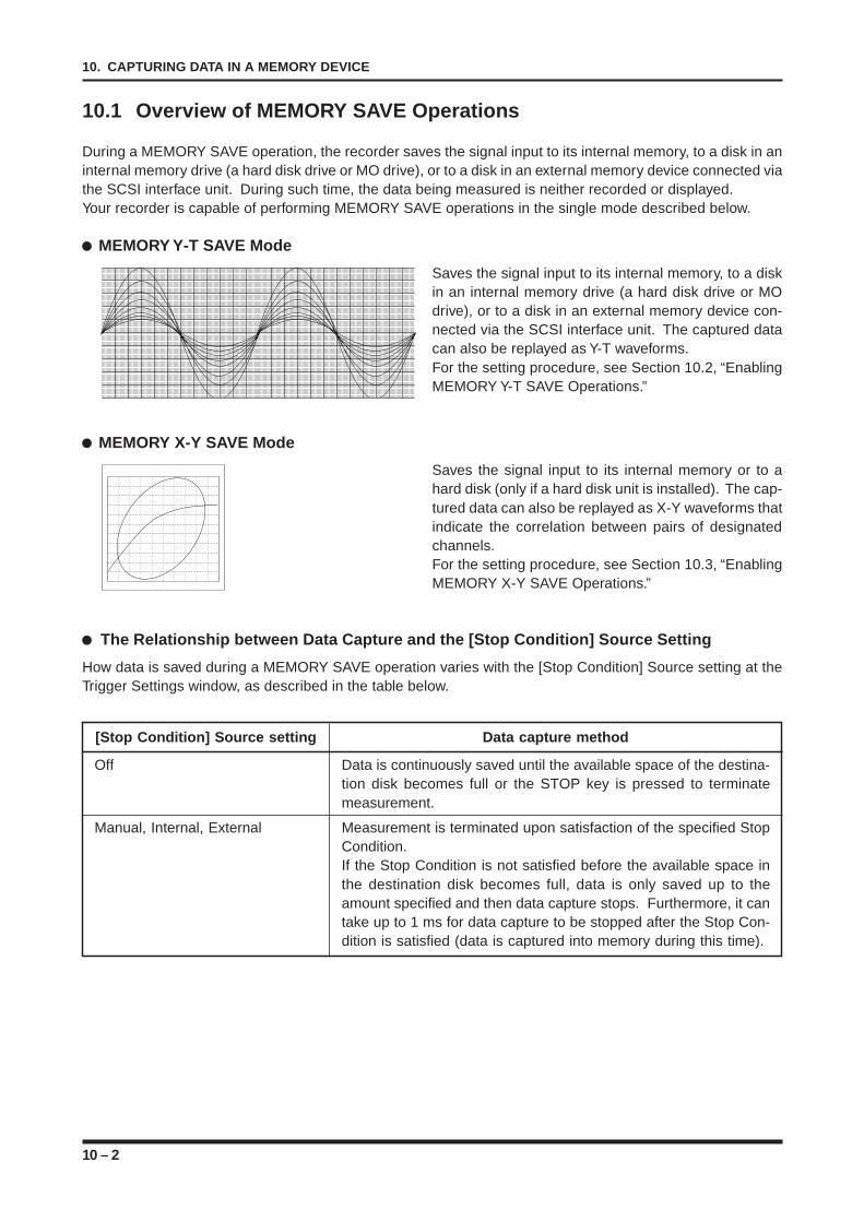
10 – 2
10. CAPTURING DATA IN A MEMORY DEVICE
10.1 Overview of MEMORY SAVE Operations
During a MEMORY SAVE operation, the recorder saves the signal input to its internal memory, to a disk in aninternal memory drive (a hard disk drive or MO drive), or to a disk in an external memory device connected viathe SCSI interface unit. During such time, the data being measured is neither recorded or displayed.Your recorder is capable of performing MEMORY SAVE operations in the single mode described below.
MEMORY Y-T SAVE Mode
Saves the signal input to its internal memory, to a diskin an internal memory drive (a hard disk drive or MOdrive), or to a disk in an external memory device con-nected via the SCSI interface unit. The captured datacan also be replayed as Y-T waveforms.For the setting procedure, see Section 10.2, “EnablingMEMORY Y-T SAVE Operations.”
MEMORY X-Y SAVE Mode
Saves the signal input to its internal memory or to ahard disk (only if a hard disk unit is installed). The cap-tured data can also be replayed as X-Y waveforms thatindicate the correlation between pairs of designatedchannels.For the setting procedure, see Section 10.3, “EnablingMEMORY X-Y SAVE Operations.”
The Relationship between Data Capture and the [Stop Condition] Source Setting
How data is saved during a MEMORY SAVE operation varies with the [Stop Condition] Source setting at theTrigger Settings window, as described in the table below.
[Stop Condition] Source setting Data capture method
Off Data is continuously saved until the available space of the destina-tion disk becomes full or the STOP key is pressed to terminatemeasurement.
Manual, Internal, External Measurement is terminated upon satisfaction of the specified StopCondition.If the Stop Condition is not satisfied before the available space inthe destination disk becomes full, data is only saved up to theamount specified and then data capture stops. Furthermore, it cantake up to 1 ms for data capture to be stopped after the Stop Con-dition is satisfied (data is captured into memory during this time).
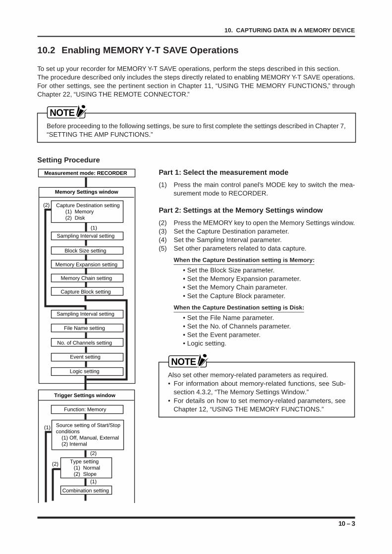
10 – 3
10. CAPTURING DATA IN A MEMORY DEVICE
Measurement mode: RECORDER
Trigger Settings window
Function: Memory
Source setting of Start/Stop conditions
(1) Off, Manual, External (2) Internal
Combination setting
(2)
(1)
(1)
Type setting(1) Normal (2) Slope
(2)
Memory Settings window
Memory Expansion setting
Block Size setting
Sampling Interval setting
Memory Chain setting
Capture Block setting
Capture Destination setting(1) Memory (2) Disk
Sampling Interval setting
File Name setting
No. of Channels setting
Logic setting
Event setting
(2)
(1)
10.2 Enabling MEMORY Y-T SAVE Operations
To set up your recorder for MEMORY Y-T SAVE operations, perform the steps described in this section.The procedure described only includes the steps directly related to enabling MEMORY Y-T SAVE operations.For other settings, see the pertinent section in Chapter 11, “USING THE MEMORY FUNCTIONS,” throughChapter 22, “USING THE REMOTE CONNECTOR.”
NOTEBefore proceeding to the following settings, be sure to first complete the settings described in Chapter 7,“SETTING THE AMP FUNCTIONS.”
Setting Procedure
Part 1: Select the measurement mode
(1) Press the main control panel’s MODE key to switch the mea-surement mode to RECORDER.
Part 2: Settings at the Memory Settings window
(2) Press the MEMORY key to open the Memory Settings window.(3) Set the Capture Destination parameter.(4) Set the Sampling Interval parameter.(5) Set other parameters related to data capture.
When the Capture Destination setting is Memory:
• Set the Block Size parameter.• Set the Memory Expansion parameter.• Set the Memory Chain parameter.• Set the Capture Block parameter.
When the Capture Destination setting is Disk:
• Set the File Name parameter.• Set the No. of Channels parameter.• Set the Event parameter.• Logic setting.
NOTEAlso set other memory-related parameters as required.• For information about memory-related functions, see Sub-
section 4.3.2, “The Memory Settings Window.”• For details on how to set memory-related parameters, see
Chapter 12, “USING THE MEMORY FUNCTIONS.”
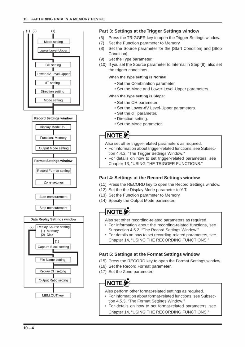
10 – 4
10. CAPTURING DATA IN A MEMORY DEVICE
Part 3: Settings at the Trigger Settings window(6) Press the TRIGGER key to open the Trigger Settings window.(7) Set the Function parameter to Memory.(8) Set the Source parameter for the [Start Condition] and [Stop
Condition].(9) Set the Type parameter.(10) If you set the Source parameter to Internal in Step (8), also set
the trigger conditions.
When the Type setting is Normal:
• Set the Combination parameter.• Set the Mode and Lower-Level-Upper parameters.
When the Type setting is Slope:
• Set the CH parameter.• Set the Lower-dV Level-Upper parameters.• Set the dT parameter.• Direction setting.• Set the Mode parameter.
NOTEAlso set other trigger-related parameters as required.• For information about trigger-related functions, see Subsec-
tion 4.4.2, “The Trigger Settings Window.”• For details on how to set trigger-related parameters, see
Chapter 13, “USING THE TRIGGER FUNCTIONS.”
Part 4: Settings at the Record Settings window(11) Press the RECORD key to open the Record Settings window.(12) Set the the Display Mode parameter to Y-T.(13) Set the Function parameter to Memory.(14) Specify the Output Mode parameter.
NOTEAlso set other recording-related parameters as required.• For information about the recording-related functions, see
Subsection 4.5.2, “The Record Settings Window.”• For details on how to set recording-related parameters, see
Chapter 14, “USING THE RECORDING FUNCTIONS.”
Part 5: Settings at the Format Settings window(15) Press the RECORD key to open the Format Settings window.(16) Set the Record Format parameter.(17) Set the Zone parameter.
NOTEAlso perform other format-related settings as required.• For information about format-related functions, see Subsec-
tion 4.5.3, “The Format Settings Window.”• For details on how to set format-related parameters, see
Chapter 14, “USING THE RECORDING FUNCTIONS.”
Data Replay Settings window
Capture Block setting
Replay Source setting(1) Memory (2) Disk
File Name setting
Replay CH setting
Output Ratio setting
MEM.OUT key
Record Settings window
Function: Memory
Output Mode setting
Format Settings window
Record Format setting
Zone settings
Display Mode: Y-T
Start measurement
Stop measurement
(2)
(1)
Lower-Level-Upper
Mode setting
CH setting
Lower-dV Level-Upper
dT setting
Direction setting
Mode setting
(1) (2) (1)
10 – 5
10. CAPTURING DATA IN A MEMORY DEVICE
Part 6: Start measurement(18) Press the CLOSE key to close the currently opened window.(19) Press the START key.(20) Press the TRIGGER key (if the [Start Condition] Source setting
at the Trigger Settings window is Manual).
Part 7: Stop measurement(21) Press the TRIGGER key (if the [Stop Condition] Source setting
at the Trigger Settings window is Manual).(22) Press the STOP key.
Part 8: Set the Replay Conditions for the Captured Data(23) Press the MEMORY key to open the Data Replay Settings win-
dow.(24) Set the Replay Source parameter.(25) Set the Capture Block or File Name parameter.
When the Replay Source setting is Memory:
• Set the Capture Block parameter.
When the Replay Source setting is Disk:
• Set the File Name parameter.
(26) Set the Replay CH parameter.(27) Set the Output Ratio parameter.
Part 9: Replay the Captured Data(28) Press the main control panel’s MEM.OUT key.
NOTE• To concurrently record the replay data onto chart paper,
press the EXECUTE key to open the EXECUTE menu andset a Printer Output operation. For instructions, see Section12.6, “Outputting Data Being Replayed onto Chart Paper.”
• During the replay of captured data, the recorder’s operatingmode switches automatically to Replay mode. In Replaymode, you cannot change any of the recorder’s settings.To change a setting, press the main control panel’s MODE/EVENT key to exit Replay mode and then proceed to thedesired window.
• If the Replay Source is Disk, do not attempt any disk opera-tions while in Replay mode. The disk may be damaged ifyou do so.

10 – 6
10. CAPTURING DATA IN A MEMORY DEVICE
10.3 Enabling MEMORY X-Y SAVE Operations
To set up your recorder for MEMORY X-Y SAVE operations, perform the steps described in this section.The procedure described only includes the steps directly related to enabling MEMORY X-Y SAVE operations.For other settings, see the pertinent section in Chapter 11, “USING THE MEMORY FUNCTIONS,” throughChapter 22, USING THE REMOTE CONNECTOR.”
NOTEBefore proceeding to the following settings, be sure to first complete the settings described in Chapter 7,“SETTING THE AMP FUNCTIONS.”
Setting Procedure
Part 1: Select the measurement mode
(1) Press the main control panel’s MODE key to switch the mea-surement mode to RECORDER.
Part 2: Settings at the Memory Settings window
(2) Press the MEMORY key to open the Memory Settings window.(3) Set the Capture Destination parameter.(4) Set the Sampling Interval parameter.(5) Set other parameters related to data capture.
When the Save To setting is Memory:
• Set the Block Size parameter.• Set the Memory Expansion parameter.• Set the Memory Chain parameter.• Set the Capture Block parameter.
When the Save To setting is Disk:
• Set the File Name parameter.• Set the No. of CHs parameter.• Set the Event parameter.• Set the Logic parameter.
NOTEAlso set other memory-related parameters as required.• For information about memory-related functions, see Sub-
section 4.3.2, “The Memory Settings Window.”• For details on how to set memory-related parameters, see
Chapter 12, “USING THE MEMORY FUNCTIONS.”
Measurement mode: RECORDER
Trigger Settings window
Function: Memory
Source setting of Start/Stop conditions
(1) Off, Manual, External (2) Internal
Combination setting
(2)
(1)
(1)
Type setting(1) Normal (2) Slope
(2)
Memory Settings window
Memory Expansion setting
Block Size setting
Sampling Interval setting
Memory Chain setting
Capture Block setting
Capture Destination setting(1) Memory (2) Disk
Sampling Interval setting
File Name setting
No. of Channels setting
Logic setting
Event setting
(2)
(1)
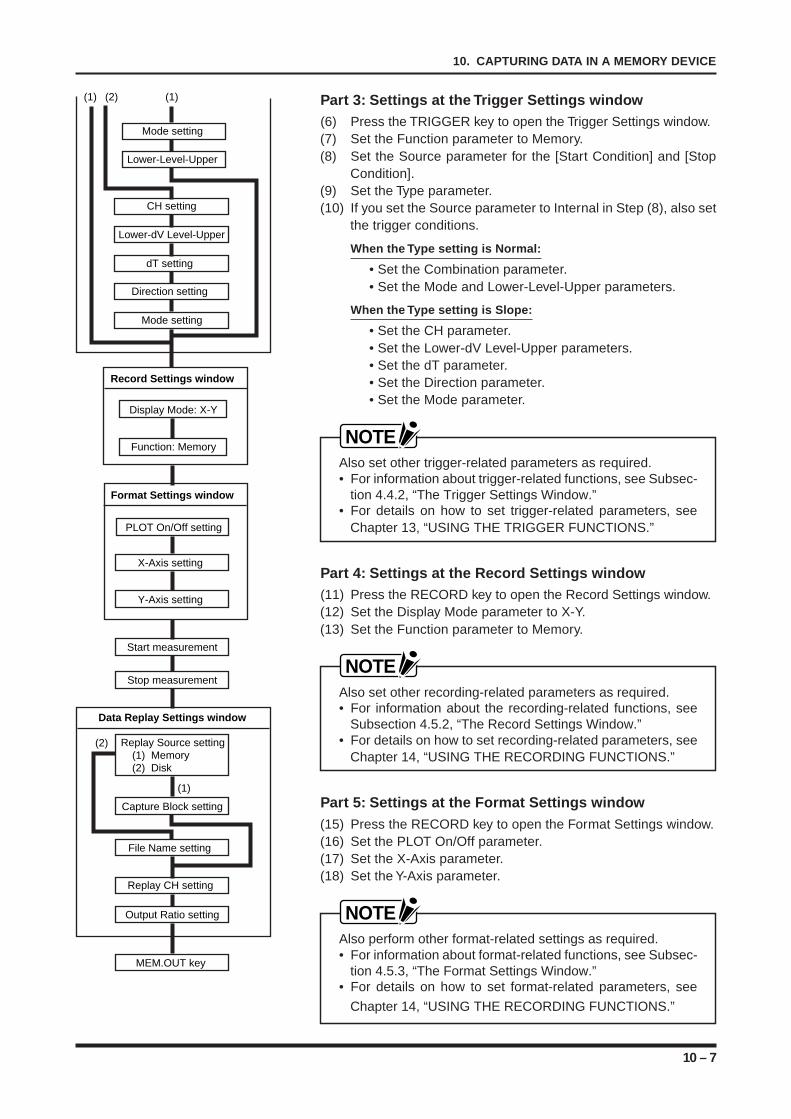
10 – 7
10. CAPTURING DATA IN A MEMORY DEVICE
Part 3: Settings at the Trigger Settings window(6) Press the TRIGGER key to open the Trigger Settings window.(7) Set the Function parameter to Memory.(8) Set the Source parameter for the [Start Condition] and [Stop
Condition].(9) Set the Type parameter.(10) If you set the Source parameter to Internal in Step (8), also set
the trigger conditions.
When the Type setting is Normal:
• Set the Combination parameter.• Set the Mode and Lower-Level-Upper parameters.
When the Type setting is Slope:
• Set the CH parameter.• Set the Lower-dV Level-Upper parameters.• Set the dT parameter.• Set the Direction parameter.• Set the Mode parameter.
NOTEAlso set other trigger-related parameters as required.• For information about trigger-related functions, see Subsec-
tion 4.4.2, “The Trigger Settings Window.”• For details on how to set trigger-related parameters, see
Chapter 13, “USING THE TRIGGER FUNCTIONS.”
Part 4: Settings at the Record Settings window(11) Press the RECORD key to open the Record Settings window.(12) Set the Display Mode parameter to X-Y.(13) Set the Function parameter to Memory.
NOTEAlso set other recording-related parameters as required.• For information about the recording-related functions, see
Subsection 4.5.2, “The Record Settings Window.”• For details on how to set recording-related parameters, see
Chapter 14, “USING THE RECORDING FUNCTIONS.”
Part 5: Settings at the Format Settings window(15) Press the RECORD key to open the Format Settings window.(16) Set the PLOT On/Off parameter.(17) Set the X-Axis parameter.(18) Set the Y-Axis parameter.
NOTEAlso perform other format-related settings as required.• For information about format-related functions, see Subsec-
tion 4.5.3, “The Format Settings Window.”• For details on how to set format-related parameters, see
Chapter 14, “USING THE RECORDING FUNCTIONS.”
Data Replay Settings window
Capture Block setting
Replay Source setting(1) Memory (2) Disk
File Name setting
Replay CH setting
Output Ratio setting
MEM.OUT key
Record Settings window
Display Mode: X-Y
Function: Memory
Format Settings window
PLOT On/Off setting
X-Axis setting
Y-Axis setting
Start measurement
Stop measurement
(2)
(1)
Lower-Level-Upper
Mode setting
CH setting
Lower-dV Level-Upper
dT setting
Direction setting
Mode setting
(1) (2) (1)
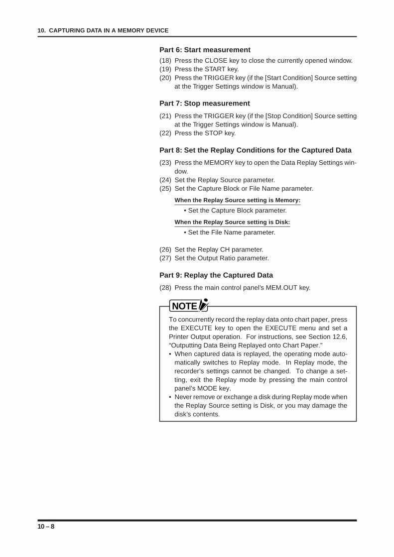
10 – 8
10. CAPTURING DATA IN A MEMORY DEVICE
Part 6: Start measurement(18) Press the CLOSE key to close the currently opened window.(19) Press the START key.(20) Press the TRIGGER key (if the [Start Condition] Source setting
at the Trigger Settings window is Manual).
Part 7: Stop measurement
(21) Press the TRIGGER key (if the [Stop Condition] Source settingat the Trigger Settings window is Manual).
(22) Press the STOP key.
Part 8: Set the Replay Conditions for the Captured Data
(23) Press the MEMORY key to open the Data Replay Settings win-dow.
(24) Set the Replay Source parameter.(25) Set the Capture Block or File Name parameter.
When the Replay Source setting is Memory:
• Set the Capture Block parameter.
When the Replay Source setting is Disk:
• Set the File Name parameter.
(26) Set the Replay CH parameter.(27) Set the Output Ratio parameter.
Part 9: Replay the Captured Data
(28) Press the main control panel’s MEM.OUT key.
NOTETo concurrently record the replay data onto chart paper, pressthe EXECUTE key to open the EXECUTE menu and set aPrinter Output operation. For instructions, see Section 12.6,“Outputting Data Being Replayed onto Chart Paper.”• When captured data is replayed, the operating mode auto-
matically switches to Replay mode. In Replay mode, therecorder’s settings cannot be changed. To change a set-ting, exit the Replay mode by pressing the main controlpanel’s MODE key.
• Never remove or exchange a disk during Replay mode whenthe Replay Source setting is Disk, or you may damage thedisk’s contents.
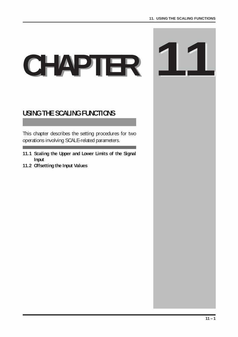
11 – 1
11. USING THE SCALING FUNCTIONS
USING THE SCALING FUNCTIONS
This chapter describes the setting procedures for twooperations involving SCALE-related parameters.
11.1 Scaling the Upper and Lower Limits of the SignalInput
11.2 Offsetting the Input Values
CHAPTER 11CHAPTER 11
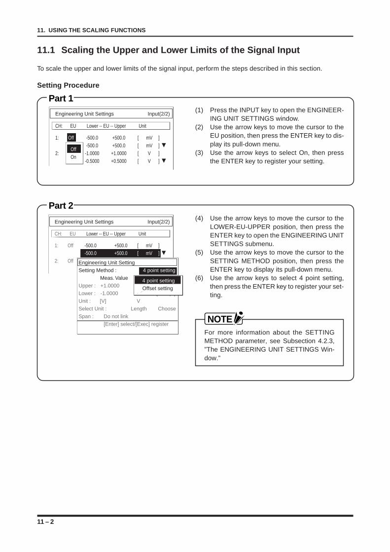
11 – 2
11. USING THE SCALING FUNCTIONS
11.1 Scaling the Upper and Lower Limits of the Signal Input
To scale the upper and lower limits of the signal input, perform the steps described in this section.
Setting Procedure
Part 1(1) Press the INPUT key to open the ENGINEER-
ING UNIT SETTINGS window.(2) Use the arrow keys to move the cursor to the
EU position, then press the ENTER key to dis-play its pull-down menu.
(3) Use the arrow keys to select On, then pressthe ENTER key to register your setting.
Part 2(4) Use the arrow keys to move the cursor to the
LOWER-EU-UPPER position, then press theENTER key to open the ENGINEERING UNITSETTINGS submenu.
(5) Use the arrow keys to move the cursor to theSETTING METHOD position, then press theENTER key to display its pull-down menu.
(6) Use the arrow keys to select 4 point setting,then press the ENTER key to register your set-ting.
NOTEFor more information about the SETTINGMETHOD parameter, see Subsection 4.2.3,”The ENGINEERING UNIT SETTINGS Win-dow.”
Engineering Unit Settings Input(2/2)
CH: EU Lower -- EU -- Upper Unit
1: Off -500.0 +500.0 [ mV ]
-500.0 +500.0 [ mV ]
2: Off -1.0000 +1.0000 [ V ]
-0.5000 +0.5000 [ V ]
Off
On
Engineering Unit Settings Input(2/2)
CH: EU Lower -- EU -- Upper Unit
1: Off -500.0 +500.0 [ mV ]
-500.0 +500.0 [ mV ]
2: Off 1.0000 1.0000 [ V ]
0.5000 0.5000 [ V ]Engineering Unit SettingSetting Method : 4 point setting
Meas. Value EU ValueUpper : +1.0000 +1.0000 Dec. ptLower : -1.0000 -1.0000 [Dec. pt]Unit : [V] VSelect Unit : Length ChooseSpan : Do not link
[Enter] select/[Exec] register
4 point setting
Offset setting
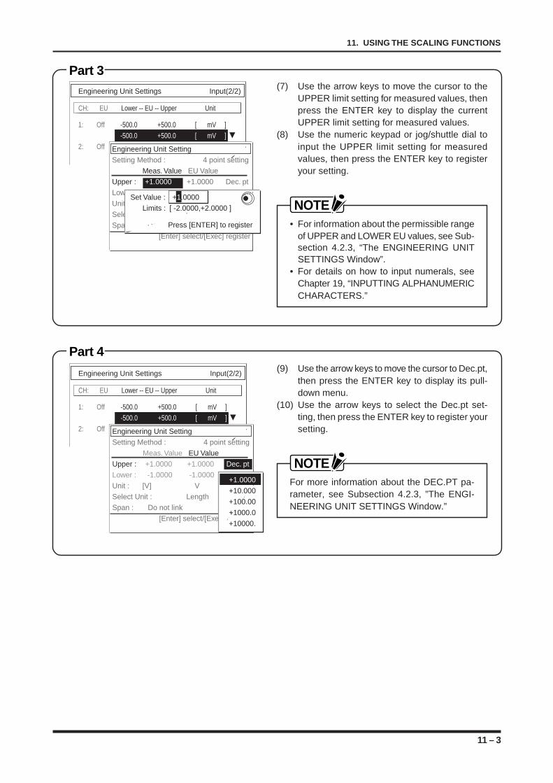
11 – 3
11. USING THE SCALING FUNCTIONS
Part 3
Part 4
(7) Use the arrow keys to move the cursor to theUPPER limit setting for measured values, thenpress the ENTER key to display the currentUPPER limit setting for measured values.
(8) Use the numeric keypad or jog/shuttle dial toinput the UPPER limit setting for measuredvalues, then press the ENTER key to registeryour setting.
NOTE• For information about the permissible range
of UPPER and LOWER EU values, see Sub-section 4.2.3, “The ENGINEERING UNITSETTINGS Window”.
• For details on how to input numerals, seeChapter 19, “INPUTTING ALPHANUMERICCHARACTERS.”
(9) Use the arrow keys to move the cursor to Dec.pt,then press the ENTER key to display its pull-down menu.
(10) Use the arrow keys to select the Dec.pt set-ting, then press the ENTER key to register yoursetting.
NOTEFor more information about the DEC.PT pa-rameter, see Subsection 4.2.3, ”The ENGI-NEERING UNIT SETTINGS Window.”
Engineering Unit Settings Input(2/2)
CH: EU Lower -- EU -- Upper Unit
1: Off -500.0 +500.0 [ mV ]
-500.0 +500.0 [ mV ]
2: Off Engineering Unit SettingSetting Method : 4 point setting
Meas. Value EU ValueUpper : +1.0000 +1.0000 Dec. ptLower : -1.0000 -1.0000 [Dec. pt]Unit : [V] VSelect Unit : Length SelectSpan : Do not link
[Enter] select/[Exec] register
Set Value : +1.0000
Limits : [ -2.0000,+2.0000 ]
Press [ENTER] to register
Engineering Unit Settings Input(2/2)
CH: EU Lower -- EU -- Upper Unit
1: Off -500.0 +500.0 [ mV ]
-500.0 +500.0 [ mV ]
2: Off Engineering Unit SettingSetting Method : 4 point setting
Meas. Value EU ValueUpper : +1.0000 +1.0000 Dec. ptLower : -1.0000 -1.0000 [Dec. pt]Unit : [V] VSelect Unit : Length SelectSpan : Do not link
[Enter] select/[Exec] register
+1.0000
+10.000
+100.00
+1000.0
+10000.
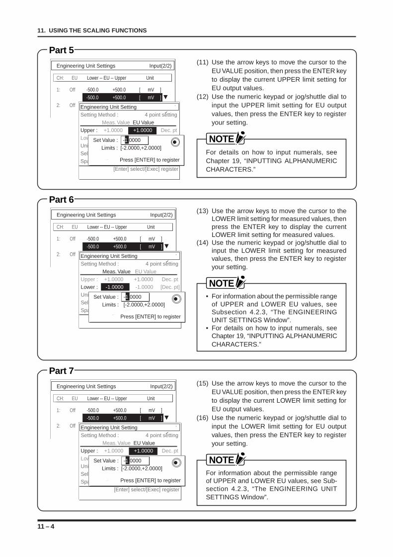
11 – 4
11. USING THE SCALING FUNCTIONS
Part 5
Part 6
Part 7
(11) Use the arrow keys to move the cursor to theEU VALUE position, then press the ENTER keyto display the current UPPER limit setting forEU output values.
(12) Use the numeric keypad or jog/shuttle dial toinput the UPPER limit setting for EU outputvalues, then press the ENTER key to registeryour setting.
NOTEFor details on how to input numerals, seeChapter 19, “INPUTTING ALPHANUMERICCHARACTERS.”
(13) Use the arrow keys to move the cursor to theLOWER limit setting for measured values, thenpress the ENTER key to display the currentLOWER limit setting for measured values.
(14) Use the numeric keypad or jog/shuttle dial toinput the LOWER limit setting for measuredvalues, then press the ENTER key to registeryour setting.
NOTE• For information about the permissible range
of UPPER and LOWER EU values, seeSubsection 4.2.3, “The ENGINEERINGUNIT SETTINGS Window”.
• For details on how to input numerals, seeChapter 19, “INPUTTING ALPHANUMERICCHARACTERS.”
(15) Use the arrow keys to move the cursor to theEU VALUE position, then press the ENTER keyto display the current LOWER limit setting forEU output values.
(16) Use the numeric keypad or jog/shuttle dial toinput the LOWER limit setting for EU outputvalues, then press the ENTER key to registeryour setting.
NOTEFor information about the permissible rangeof UPPER and LOWER EU values, see Sub-section 4.2.3, “The ENGINEERING UNITSETTINGS Window”.
Engineering Unit Settings Input(2/2)
CH: EU Lower -- EU -- Upper Unit
1: Off -500.0 +500.0 [ mV ]
-500.0 +500.0 [ mV ]
2: Off Engineering Unit SettingSetting Method : 4 point setting
Meas. Value EU ValueUpper : +1.0000 +1.0000 Dec. ptLower : -1.0000 -1.0000 [Dec. pt]Unit : [V] VSelect Unit : Length SelectSpan : Do not link
[Enter] select/[Exec] register
Set Value : -1.0000
Limits : [-2.0000,+2.0000]
Press [ENTER] to register
Engineering Unit Settings Input(2/2)
CH: EU Lower -- EU -- Upper Unit
1: Off -500.0 +500.0 [ mV ]
-500.0 +500.0 [ mV ]
2: Off Engineering Unit SettingSetting Method : 4 point setting
Meas. Value EU ValueUpper : +1.0000 +1.0000 Dec. ptLower : -1.0000 -1.0000 [Dec. pt]Unit : [V] VSelect Unit : Length SelectSpan : Do not link
[Enter] select/[Exec] register
Set Value : -1.0000
Limits : [-2.0000,+2.0000]
Press [ENTER] to register
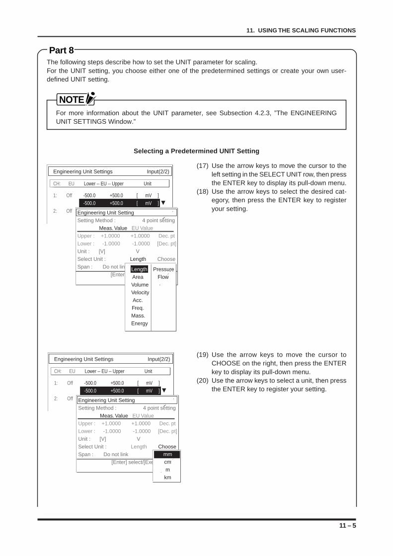
11 – 5
11. USING THE SCALING FUNCTIONS
Part 8The following steps describe how to set the UNIT parameter for scaling.For the UNIT setting, you choose either one of the predetermined settings or create your own user-defined UNIT setting.
NOTEFor more information about the UNIT parameter, see Subsection 4.2.3, ”The ENGINEERINGUNIT SETTINGS Window.”
Selecting a Predetermined UNIT Setting
(17) Use the arrow keys to move the cursor to theleft setting in the SELECT UNIT row, then pressthe ENTER key to display its pull-down menu.
(18) Use the arrow keys to select the desired cat-egory, then press the ENTER key to registeryour setting.
(19) Use the arrow keys to move the cursor toCHOOSE on the right, then press the ENTERkey to display its pull-down menu.
(20) Use the arrow keys to select a unit, then pressthe ENTER key to register your setting.
Engineering Unit Settings Input(2/2)
CH: EU Lower -- EU -- Upper Unit
1: Off -500.0 +500.0 [ mV ]
-500.0 +500.0 [ mV ]
2: Off Engineering Unit SettingSetting Method : 4 point setting
Meas. Value EU ValueUpper : +1.0000 +1.0000 Dec. ptLower : -1.0000 -1.0000 [Dec. pt]Unit : [V] VSelect Unit : Length ChooseSpan : Do not link
[Enter] select/[Exec] registerLength PressureArea FlowVolumeVelocityAcc.Freq.Mass.Energy
Engineering Unit Settings Input(2/2)
CH: EU Lower -- EU -- Upper Unit
1: Off -500.0 +500.0 [ mV ]
-500.0 +500.0 [ mV ]
2: Off Engineering Unit SettingSetting Method : 4 point setting
Meas. Value EU ValueUpper : +1.0000 +1.0000 Dec. ptLower : -1.0000 -1.0000 [Dec. pt]Unit : [V] VSelect Unit : Length ChooseSpan : Do not link
[Enter] select/[Exec] register
mmcmmkm
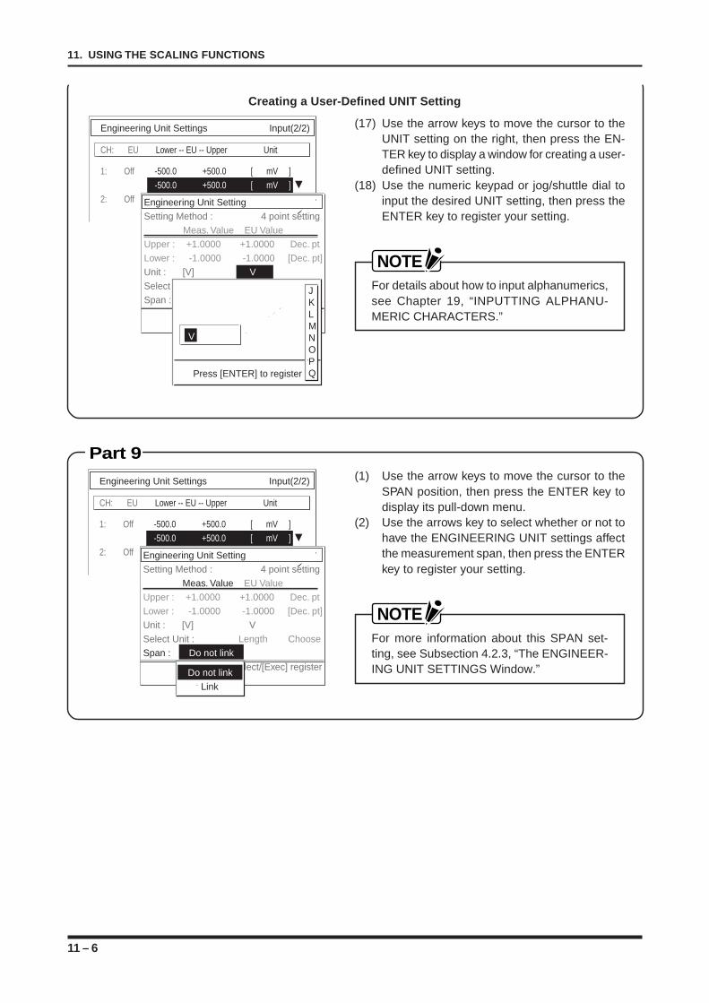
11 – 6
11. USING THE SCALING FUNCTIONS
Part 9
Creating a User-Defined UNIT Setting
(17) Use the arrow keys to move the cursor to theUNIT setting on the right, then press the EN-TER key to display a window for creating a user-defined UNIT setting.
(18) Use the numeric keypad or jog/shuttle dial toinput the desired UNIT setting, then press theENTER key to register your setting.
NOTEFor details about how to input alphanumerics,see Chapter 19, “INPUTTING ALPHANU-MERIC CHARACTERS.”
(1) Use the arrow keys to move the cursor to theSPAN position, then press the ENTER key todisplay its pull-down menu.
(2) Use the arrows key to select whether or not tohave the ENGINEERING UNIT settings affectthe measurement span, then press the ENTERkey to register your setting.
NOTEFor more information about this SPAN set-ting, see Subsection 4.2.3, “The ENGINEER-ING UNIT SETTINGS Window.”
Engineering Unit Settings Input(2/2)
CH: EU Lower -- EU -- Upper Unit
1: Off -500.0 +500.0 [ mV ]
-500.0 +500.0 [ mV ]
2: Off Engineering Unit SettingSetting Method : 4 point setting
Meas. Value EU ValueUpper : +1.0000 +1.0000 Dec. ptLower : -1.0000 -1.0000 [Dec. pt]Unit : [V] VSelect Unit : Length SelectSpan : Do not link
[Enter] select/[Exec] register
V
Press [ENTER] to register
JKLMNOPQ
Engineering Unit Settings Input(2/2)
CH: EU Lower -- EU -- Upper Unit
1: Off -500.0 +500.0 [ mV ]
-500.0 +500.0 [ mV ]
2: Off Engineering Unit SettingSetting Method : 4 point setting
Meas. Value EU ValueUpper : +1.0000 +1.0000 Dec. ptLower : -1.0000 -1.0000 [Dec. pt]Unit : [V] VSelect Unit : Length ChooseSpan : Do not link
[Enter] select/[Exec] registerDo not link Link
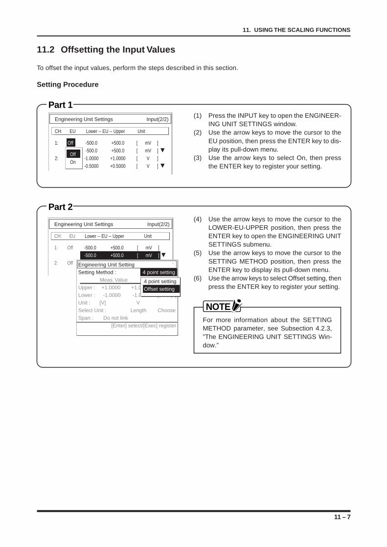
11 – 7
11. USING THE SCALING FUNCTIONS
11.2 Offsetting the Input Values
To offset the input values, perform the steps described in this section.
Setting Procedure
(1) Press the INPUT key to open the ENGINEER-ING UNIT SETTINGS window.
(2) Use the arrow keys to move the cursor to theEU position, then press the ENTER key to dis-play its pull-down menu.
(3) Use the arrow keys to select On, then pressthe ENTER key to register your setting.
Part 1
Part 2(4) Use the arrow keys to move the cursor to the
LOWER-EU-UPPER position, then press theENTER key to open the ENGINEERING UNITSETTINGS submenu.
(5) Use the arrow keys to move the cursor to theSETTING METHOD position, then press theENTER key to display its pull-down menu.
(6) Use the arrow keys to select Offset setting, thenpress the ENTER key to register your setting.
NOTEFor more information about the SETTINGMETHOD parameter, see Subsection 4.2.3,”The ENGINEERING UNIT SETTINGS Win-dow.”
Engineering Unit Settings Input(2/2)
CH: EU Lower -- EU -- Upper Unit
1: Off -500.0 +500.0 [ mV ]
-500.0 +500.0 [ mV ]
2: Off Engineering Unit SettingSetting Method : 4 point setting
Meas. Value EU ValueUpper : +1.0000 +1.0000 Dec. ptLower : -1.0000 -1.0000 [Dec. pt]Unit : [V] VSelect Unit : Length ChooseSpan : Do not link
[Enter] select/[Exec] register
4 point setting
Offset setting
Engineering Unit Settings Input(2/2)
CH: EU Lower -- EU -- Upper Unit
1: Off -500.0 +500.0 [ mV ]
-500.0 +500.0 [ mV ]
2: Off -1.0000 +1.0000 [ V ]
-0.5000 +0.5000 [ V ]
Off
On
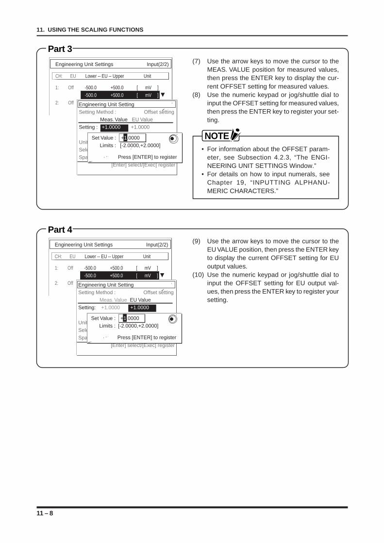
11 – 8
11. USING THE SCALING FUNCTIONS
Part 3
Part 4
(7) Use the arrow keys to move the cursor to theMEAS. VALUE position for measured values,then press the ENTER key to display the cur-rent OFFSET setting for measured values.
(8) Use the numeric keypad or jog/shuttle dial toinput the OFFSET setting for measured values,then press the ENTER key to register your set-ting.
NOTE• For information about the OFFSET param-
eter, see Subsection 4.2.3, “The ENGI-NEERING UNIT SETTINGS Window.”
• For details on how to input numerals, seeChapter 19, “INPUTTING ALPHANU-MERIC CHARACTERS.”
(9) Use the arrow keys to move the cursor to theEU VALUE position, then press the ENTER keyto display the current OFFSET setting for EUoutput values.
(10) Use the numeric keypad or jog/shuttle dial toinput the OFFSET setting for EU output val-ues, then press the ENTER key to register yoursetting.
Engineering Unit Settings Input(2/2)
CH: EU Lower -- EU -- Upper Unit
1: Off -500.0 +500.0 [ mV ]
-500.0 +500.0 [ mV ]
2: Off Engineering Unit SettingSetting Method : Offset setting
Meas. Value EU ValueSetting: +1.0000 +1.0000
-1.0000 -1.0000 [Dec. pt]Unit : [V] VSelect Unit : Length SelectSpan : Do not link
[Enter] select/[Exec] register
Set Value : +1.0000
Limits : [-2.0000,+2.0000]
Press [ENTER] to register
Engineering Unit Settings Input(2/2)
CH: EU Lower -- EU -- Upper Unit
1: Off -500.0 +500.0 [ mV ]
-500.0 +500.0 [ mV ]
2: Off Engineering Unit SettingSetting Method : Offset setting
Meas. Value EU ValueSetting : +1.0000 +1.0000 -1.0000 -1.0000 [Dec. pt]Unit : [V] VSelect Unit : Length SelectSpan : Do not link
[Enter] select/[Exec] register
Set Value : +1.0000
Limits : [-2.0000,+2.0000]
Press [ENTER] to register
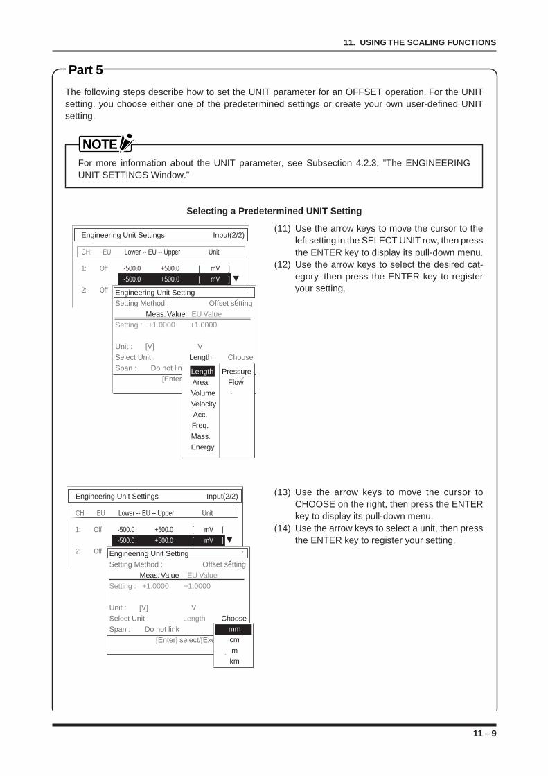
11 – 9
11. USING THE SCALING FUNCTIONS
Part 5
The following steps describe how to set the UNIT parameter for an OFFSET operation. For the UNITsetting, you choose either one of the predetermined settings or create your own user-defined UNITsetting.
NOTEFor more information about the UNIT parameter, see Subsection 4.2.3, ”The ENGINEERINGUNIT SETTINGS Window.”
Selecting a Predetermined UNIT Setting
(11) Use the arrow keys to move the cursor to theleft setting in the SELECT UNIT row, then pressthe ENTER key to display its pull-down menu.
(12) Use the arrow keys to select the desired cat-egory, then press the ENTER key to registeryour setting.
(13) Use the arrow keys to move the cursor toCHOOSE on the right, then press the ENTERkey to display its pull-down menu.
(14) Use the arrow keys to select a unit, then pressthe ENTER key to register your setting.
Engineering Unit Settings Input(2/2)
CH: EU Lower -- EU -- Upper Unit
1: Off -500.0 +500.0 [ mV ]
-500.0 +500.0 [ mV ]
2: Off Engineering Unit SettingSetting Method : Offset setting
Meas. Value EU ValueSetting : +1.0000 +1.0000
Unit : [V] VSelect Unit : Length ChooseSpan : Do not link
[Enter] select/[Exec] registerLength PressureArea FlowVolumeVelocityAcc.Freq.Mass.Energy
Engineering Unit Settings Input(2/2)
CH: EU Lower -- EU -- Upper Unit
1: Off -500.0 +500.0 [ mV ]
-500.0 +500.0 [ mV ]
2: Off Engineering Unit SettingSetting Method : Offset setting
Meas. Value EU ValueSetting : +1.0000 +1.0000
Unit : [V] VSelect Unit : Length ChooseSpan : Do not link
[Enter] select/[Exec] register
mmcmmkm
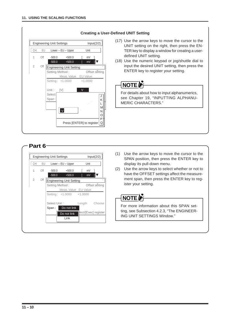
11 – 10
11. USING THE SCALING FUNCTIONS
Creating a User-Defined UNIT Setting
(17) Use the arrow keys to move the cursor to theUNIT setting on the right, then press the EN-TER key to display a window for creating a user-defined UNIT setting.
(18) Use the numeric keypad or jog/shuttle dial toinput the desired UNIT setting, then press theENTER key to register your setting.
NOTEFor details about how to input alphanumerics,see Chapter 19, “INPUTTING ALPHANU-MERIC CHARACTERS.”
(1) Use the arrow keys to move the cursor to theSPAN position, then press the ENTER key todisplay its pull-down menu.
(2) Use the arrow keys to select whether or not tohave the OFFSET settings affect the measure-ment span, then press the ENTER key to reg-ister your setting.
NOTEFor more information about this SPAN set-ting, see Subsection 4.2.3, “The ENGINEER-ING UNIT SETTINGS Window.”
Part 6
Engineering Unit Settings Input(2/2)
CH: EU Lower -- EU -- Upper Unit
1: Off -500.0 +500.0 [ mV ]
-500.0 +500.0 [ mV ]
2: Off Engineering Unit SettingSetting Method : Offset setting
Meas. Value EU ValueSetting : +1.0000 +1.0000
Unit : [V] VSelect Unit : Length SelectSpan : Do not link
[Enter] select/[Exec] register
V
Press [ENTER] to register
JKLMNOPQ
Engineering Unit Settings Input(2/2)
CH: EU Lower -- EU -- Upper Unit
1: Off -500.0 +500.0 [ mV ]
-500.0 +500.0 [ mV ]
2: Off Engineering Unit SettingSetting Method : Offset setting
Meas. Value EU ValueSetting : +1.0000 +1.0000
Select Unit : Length ChooseSpan : Do not link
[Enter] select/[Exec] registerDo not link Link
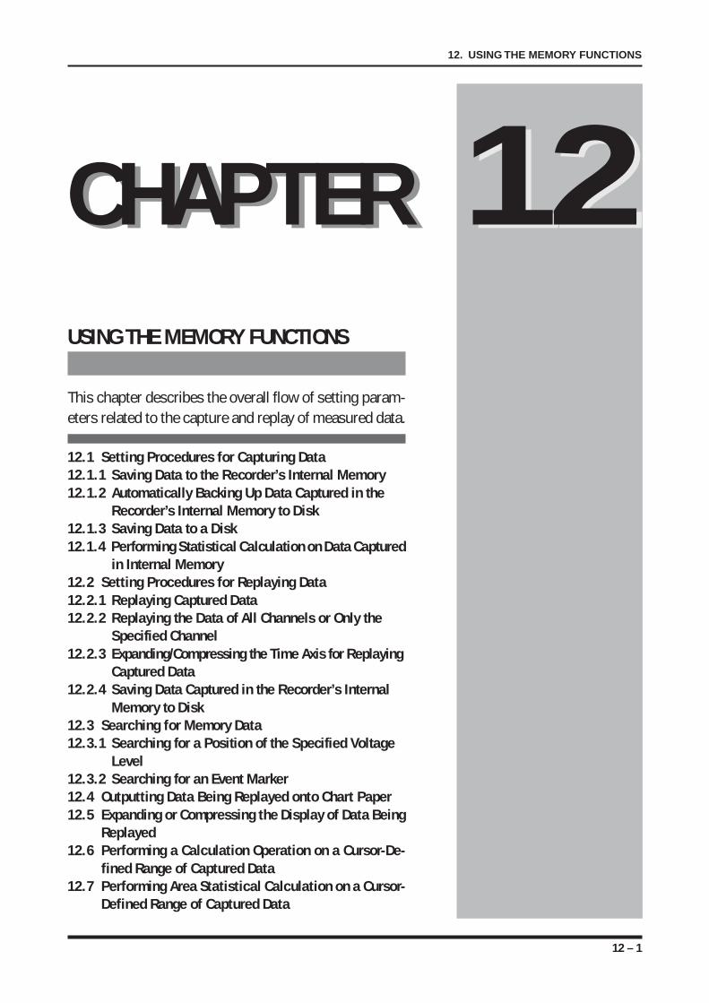
12 – 1
12. USING THE MEMORY FUNCTIONS
USING THE MEMORY FUNCTIONS
This chapter describes the overall flow of setting param-eters related to the capture and replay of measured data.
12.1 Setting Procedures for Capturing Data12.1.1 Saving Data to the Recorder’s Internal Memory12.1.2 Automatically Backing Up Data Captured in the
Recorder’s Internal Memory to Disk12.1.3 Saving Data to a Disk12.1.4 Performing Statistical Calculation on Data Captured
in Internal Memory12.2 Setting Procedures for Replaying Data12.2.1 Replaying Captured Data12.2.2 Replaying the Data of All Channels or Only the
Specified Channel12.2.3 Expanding/Compressing the Time Axis for Replaying
Captured Data12.2.4 Saving Data Captured in the Recorder’s Internal
Memory to Disk12.3 Searching for Memory Data12.3.1 Searching for a Position of the Specified Voltage
Level12.3.2 Searching for an Event Marker12.4 Outputting Data Being Replayed onto Chart Paper12.5 Expanding or Compressing the Display of Data Being
Replayed12.6 Performing a Calculation Operation on a Cursor-De-
fined Range of Captured Data12.7 Performing Area Statistical Calculation on a Cursor-
Defined Range of Captured Data
CHAPTER 12CHAPTER 12
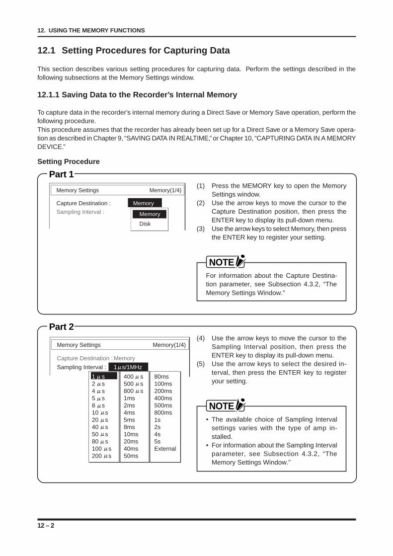
12 – 2
12. USING THE MEMORY FUNCTIONS
12.1 Setting Procedures for Capturing Data
This section describes various setting procedures for capturing data. Perform the settings described in thefollowing subsections at the Memory Settings window.
12.1.1 Saving Data to the Recorder’s Internal Memory
To capture data in the recorder’s internal memory during a Direct Save or Memory Save operation, perform thefollowing procedure.This procedure assumes that the recorder has already been set up for a Direct Save or a Memory Save opera-tion as described in Chapter 9, “SAVING DATA IN REALTIME,” or Chapter 10, “CAPTURING DATA IN A MEMORYDEVICE.”
Memory Settings Memory(1/4)
Capture Destination : Memory
Sampling Interval : 1ms/1kHzMemory
Disk
Memory Settings Memory(1/4)
Capture Destination : Memory
Sampling Interval : 1 s/1MHz
1 s 400 s 80ms2 s 500 s 100ms4 s 800 s 200ms5 s 1ms 400ms8 s 2ms 500ms10 s 4ms 800ms20 s 5ms 1s40 s 8ms 2s50 s 10ms 4s80 s 20ms 5s100 s 40ms External200 s 50ms
(1) Press the MEMORY key to open the MemorySettings window.
(2) Use the arrow keys to move the cursor to theCapture Destination position, then press theENTER key to display its pull-down menu.
(3) Use the arrow keys to select Memory, then pressthe ENTER key to register your setting.
NOTEFor information about the Capture Destina-tion parameter, see Subsection 4.3.2, “TheMemory Settings Window.”
Part 2(4) Use the arrow keys to move the cursor to the
Sampling Interval position, then press theENTER key to display its pull-down menu.
(5) Use the arrow keys to select the desired in-terval, then press the ENTER key to registeryour setting.
NOTE• The available choice of Sampling Interval
settings varies with the type of amp in-stalled.
• For information about the Sampling Intervalparameter, see Subsection 4.3.2, “TheMemory Settings Window.”
Setting Procedure
Part 1
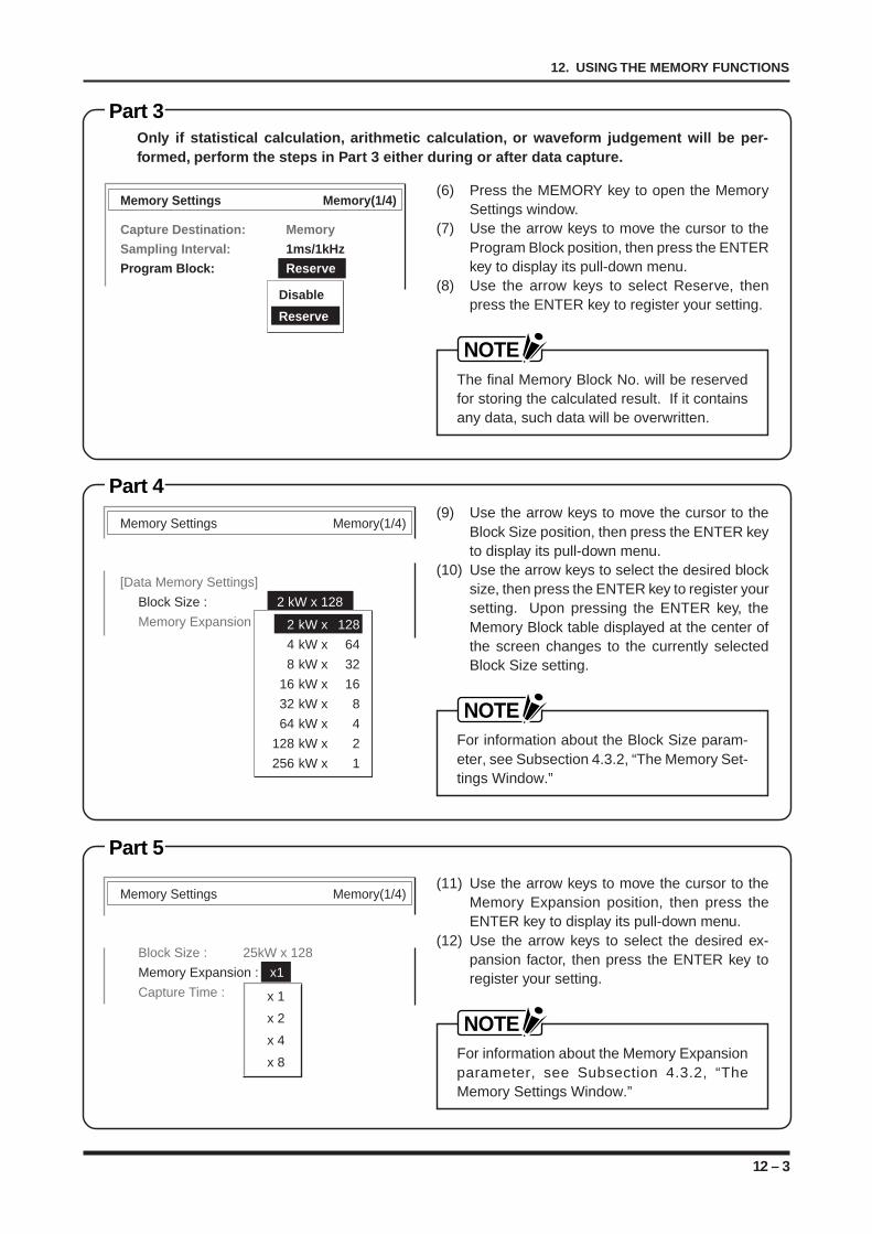
12 – 3
12. USING THE MEMORY FUNCTIONS
Memory Settings Memory(1/4)
[Data Memory Settings]
Block Size : 2 kW x 128
Memory Expansion 2 kW x 128
4 kW x 64
8 kW x 32
16 kW x 16
32 kW x 8
64 kW x 4
128 kW x 2
256 kW x 1
Memory Settings Memory(1/4)
Block Size : 25kW x 128
Memory Expansion : x1
Capture Time : x 1
x 2
x 4
x 8
Part 4
Part 5
(9) Use the arrow keys to move the cursor to theBlock Size position, then press the ENTER keyto display its pull-down menu.
(10) Use the arrow keys to select the desired blocksize, then press the ENTER key to register yoursetting. Upon pressing the ENTER key, theMemory Block table displayed at the center ofthe screen changes to the currently selectedBlock Size setting.
NOTEFor information about the Block Size param-eter, see Subsection 4.3.2, “The Memory Set-tings Window.”
(11) Use the arrow keys to move the cursor to theMemory Expansion position, then press theENTER key to display its pull-down menu.
(12) Use the arrow keys to select the desired ex-pansion factor, then press the ENTER key toregister your setting.
NOTEFor information about the Memory Expansionparameter, see Subsection 4.3.2, “TheMemory Settings Window.”
Part 3
(6) Press the MEMORY key to open the MemorySettings window.
(7) Use the arrow keys to move the cursor to theProgram Block position, then press the ENTERkey to display its pull-down menu.
(8) Use the arrow keys to select Reserve, thenpress the ENTER key to register your setting.
NOTEThe final Memory Block No. will be reservedfor storing the calculated result. If it containsany data, such data will be overwritten.
Memory Settings Memory(1/4)
Capture Destination: Memory
Sampling Interval: 1ms/1kHz
Program Block: Reserve
Disable
Reserve
Only if statistical calculation, arithmetic calculation, or waveform judgement will be per-formed, perform the steps in Part 3 either during or after data capture.
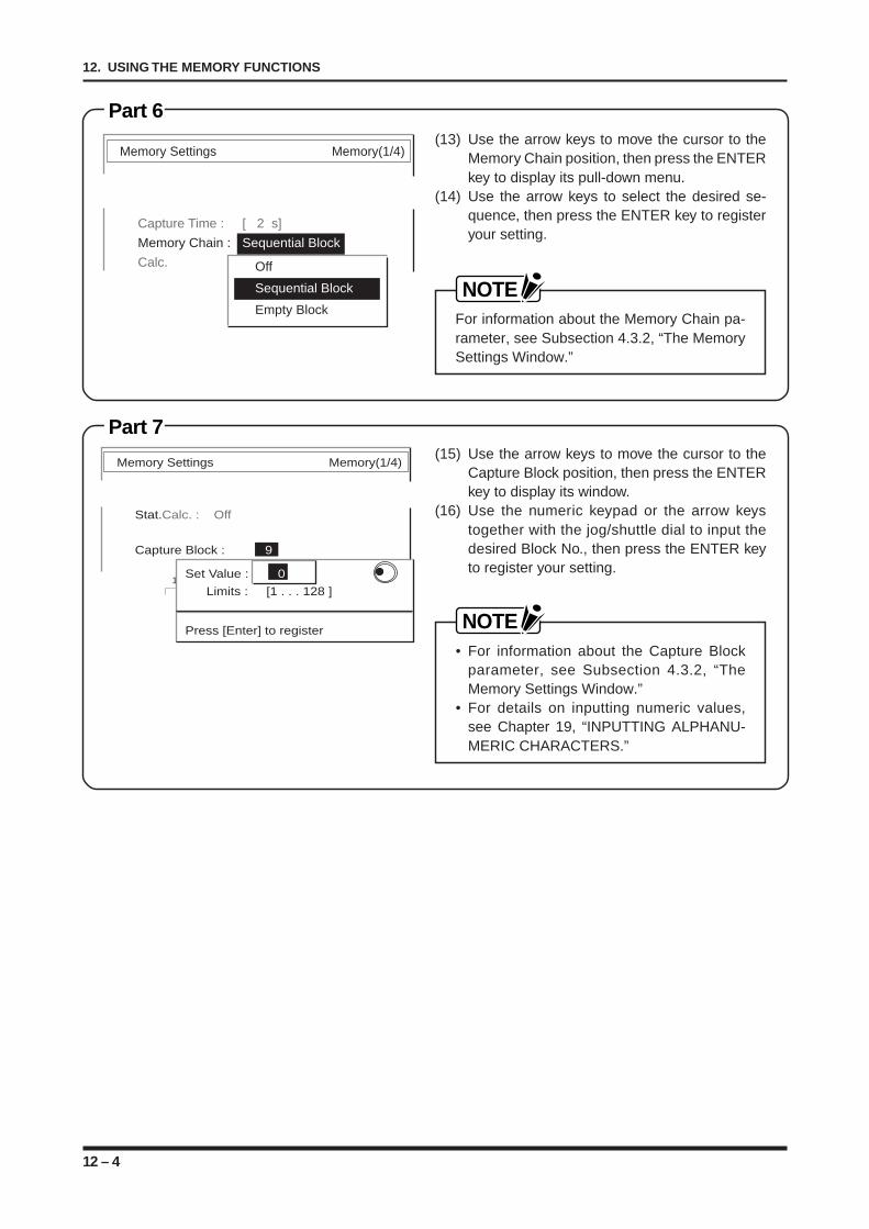
12 – 4
12. USING THE MEMORY FUNCTIONS
Memory Settings Memory(1/4)
Stat.Calc. : Off
Capture Block : 9
1 2 3 4 5 6 7 8 9 10 Set Value : 0
Limits : [1 . . . 128 ]
Press [Enter] to register
Part 7(15) Use the arrow keys to move the cursor to the
Capture Block position, then press the ENTERkey to display its window.
(16) Use the numeric keypad or the arrow keystogether with the jog/shuttle dial to input thedesired Block No., then press the ENTER keyto register your setting.
NOTE• For information about the Capture Block
parameter, see Subsection 4.3.2, “TheMemory Settings Window.”
• For details on inputting numeric values,see Chapter 19, “INPUTTING ALPHANU-MERIC CHARACTERS.”
Part 6(13) Use the arrow keys to move the cursor to the
Memory Chain position, then press the ENTERkey to display its pull-down menu.
(14) Use the arrow keys to select the desired se-quence, then press the ENTER key to registeryour setting.
NOTEFor information about the Memory Chain pa-rameter, see Subsection 4.3.2, “The MemorySettings Window.”
Memory Settings Memory(1/4)
Capture Time : [ 2 s]
Memory Chain : Sequential Block
Calc. Off
Sequential Block
Empty Block
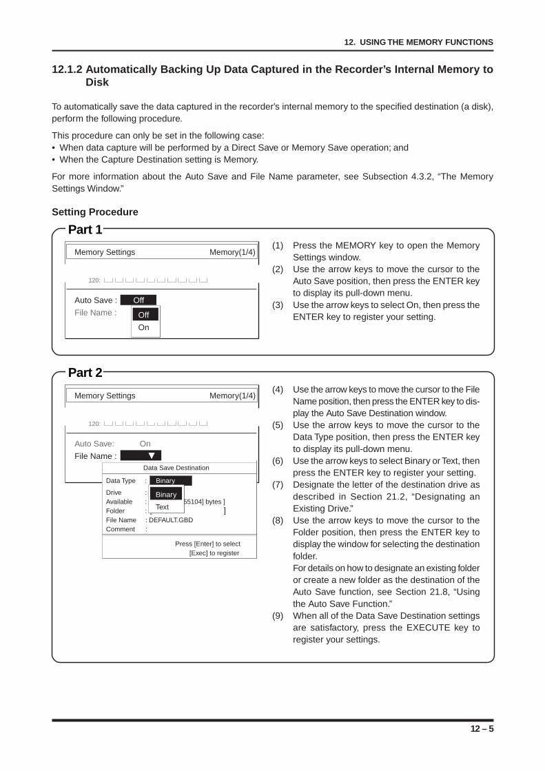
12 – 5
12. USING THE MEMORY FUNCTIONS
12.1.2 Automatically Backing Up Data Captured in the Recorder’s Internal Memory toDisk
To automatically save the data captured in the recorder’s internal memory to the specified destination (a disk),perform the following procedure.
This procedure can only be set in the following case:• When data capture will be performed by a Direct Save or Memory Save operation; and• When the Capture Destination setting is Memory.
For more information about the Auto Save and File Name parameter, see Subsection 4.3.2, “The MemorySettings Window.”
Part 2(4) Use the arrow keys to move the cursor to the File
Name position, then press the ENTER key to dis-play the Auto Save Destination window.
(5) Use the arrow keys to move the cursor to theData Type position, then press the ENTER keyto display its pull-down menu.
(6) Use the arrow keys to select Binary or Text, thenpress the ENTER key to register your setting.
(7) Designate the letter of the destination drive asdescribed in Section 21.2, “Designating anExisting Drive.”
(8) Use the arrow keys to move the cursor to theFolder position, then press the ENTER key todisplay the window for selecting the destinationfolder.For details on how to designate an existing folderor create a new folder as the destination of theAuto Save function, see Section 21.8, “Usingthe Auto Save Function.”
(9) When all of the Data Save Destination settingsare satisfactory, press the EXECUTE key toregister your settings.
Memory Settings Memory(1/4)
120:
Auto Save: On
File Name :Data Save Destination
Data Type : Binary
Drive : A : FDDAvailable : [ 1455104] bytes ]Folder : [ ]File Name : DEFAULT.GBDComment :
Press [Enter] to select[Exec] to register
Binary
Text
Setting Procedure
Part 1(1) Press the MEMORY key to open the Memory
Settings window.(2) Use the arrow keys to move the cursor to the
Auto Save position, then press the ENTER keyto display its pull-down menu.
(3) Use the arrow keys to select On, then press theENTER key to register your setting.
Memory Settings Memory(1/4)
120:
Auto Save : Off
File Name : Off
On
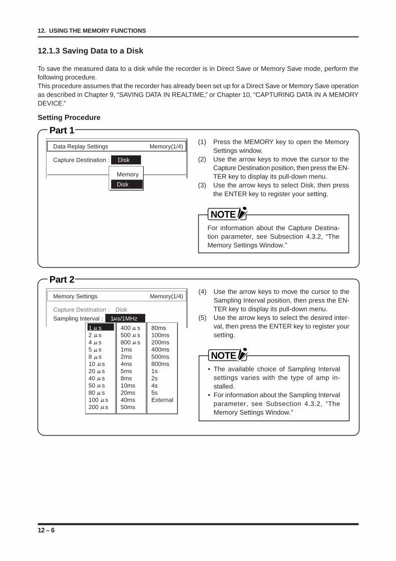
12 – 6
12. USING THE MEMORY FUNCTIONS
Part 2
12.1.3 Saving Data to a Disk
To save the measured data to a disk while the recorder is in Direct Save or Memory Save mode, perform thefollowing procedure.This procedure assumes that the recorder has already been set up for a Direct Save or Memory Save operationas described in Chapter 9, “SAVING DATA IN REALTIME,” or Chapter 10, “CAPTURING DATA IN A MEMORYDEVICE.”
Setting Procedure
Part 1(1) Press the MEMORY key to open the Memory
Settings window.(2) Use the arrow keys to move the cursor to the
Capture Destination position, then press the EN-TER key to display its pull-down menu.
(3) Use the arrow keys to select Disk, then pressthe ENTER key to register your setting.
NOTEFor information about the Capture Destina-tion parameter, see Subsection 4.3.2, “TheMemory Settings Window.”
(4) Use the arrow keys to move the cursor to theSampling Interval position, then press the EN-TER key to display its pull-down menu.
(5) Use the arrow keys to select the desired inter-val, then press the ENTER key to register yoursetting.
NOTE• The available choice of Sampling Interval
settings varies with the type of amp in-stalled.
• For information about the Sampling Intervalparameter, see Subsection 4.3.2, “TheMemory Settings Window.”
Memory Settings Memory(1/4)
Capture Destination : Disk
Sampling Interval : 1 s/1MHz
1 s 400 s 80ms2 s 500 s 100ms4 s 800 s 200ms5 s 1ms 400ms8 s 2ms 500ms10 s 4ms 800ms20 s 5ms 1s40 s 8ms 2s50 s 10ms 4s80 s 20ms 5s100 s 40ms External200 s 50ms
Data Replay Settings Memory(1/4)
Capture Destination : Disk
Memory
Disk
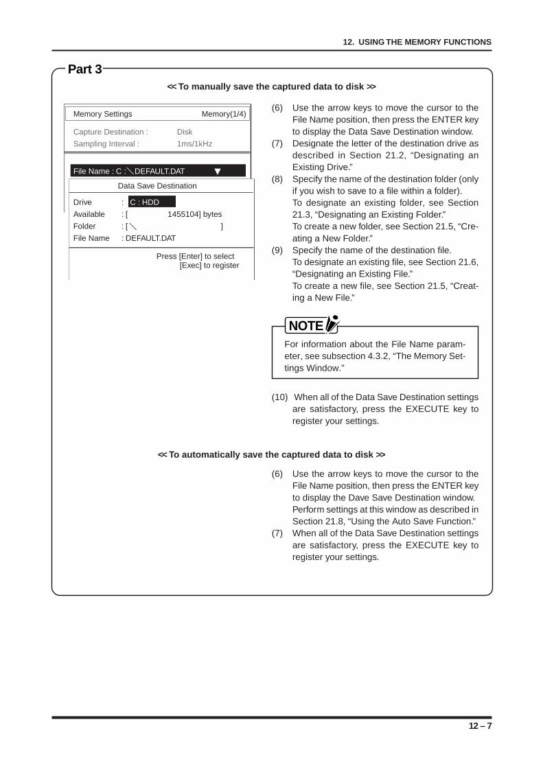
12 – 7
12. USING THE MEMORY FUNCTIONS
Part 3
Memory Settings Memory(1/4)
Capture Destination : Disk
Sampling Interval : 1ms/1kHz
File Name : C : DEFAULT.DAT
Data Save Destination
Drive : C : HDD
Available : [ 1455104] bytes
Folder : [ ]
File Name : DEFAULT.DAT
Press [Enter] to select[Exec] to register
(6) Use the arrow keys to move the cursor to theFile Name position, then press the ENTER keyto display the Data Save Destination window.
(7) Designate the letter of the destination drive asdescribed in Section 21.2, “Designating anExisting Drive.”
(8) Specify the name of the destination folder (onlyif you wish to save to a file within a folder).To designate an existing folder, see Section21.3, “Designating an Existing Folder.”To create a new folder, see Section 21.5, “Cre-ating a New Folder.”
(9) Specify the name of the destination file.To designate an existing file, see Section 21.6,“Designating an Existing File.”To create a new file, see Section 21.5, “Creat-ing a New File.”
NOTEFor information about the File Name param-eter, see subsection 4.3.2, “The Memory Set-tings Window.”
(10) When all of the Data Save Destination settingsare satisfactory, press the EXECUTE key toregister your settings.
<< To manually save the captured data to disk >>
<< To automatically save the captured data to disk >>
(6) Use the arrow keys to move the cursor to theFile Name position, then press the ENTER keyto display the Dave Save Destination window.Perform settings at this window as described inSection 21.8, “Using the Auto Save Function.”
(7) When all of the Data Save Destination settingsare satisfactory, press the EXECUTE key toregister your settings.
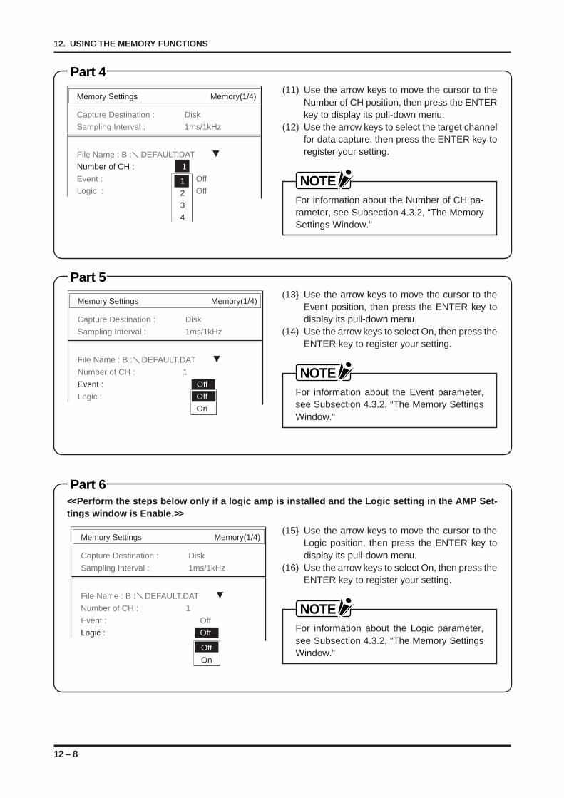
12 – 8
12. USING THE MEMORY FUNCTIONS
Part 4
Memory Settings Memory(1/4)
Capture Destination : Disk
Sampling Interval : 1ms/1kHz
File Name : B : DEFAULT.DAT
Number of CH : 1
Event : Off
Logic : Off1
2
3
4
(11) Use the arrow keys to move the cursor to theNumber of CH position, then press the ENTERkey to display its pull-down menu.
(12) Use the arrow keys to select the target channelfor data capture, then press the ENTER key toregister your setting.
NOTEFor information about the Number of CH pa-rameter, see Subsection 4.3.2, “The MemorySettings Window.”
Part 5
Memory Settings Memory(1/4)
Capture Destination : Disk
Sampling Interval : 1ms/1kHz
File Name : B : DEFAULT.DAT
Number of CH : 1
Event : Off
Logic : OffOff
On
(13 Use the arrow keys to move the cursor to theEvent position, then press the ENTER key todisplay its pull-down menu.
(14) Use the arrow keys to select On, then press theENTER key to register your setting.
NOTEFor information about the Event parameter,see Subsection 4.3.2, “The Memory SettingsWindow.”
Part 6
Memory Settings Memory(1/4)
Capture Destination : Disk
Sampling Interval : 1ms/1kHz
File Name : B : DEFAULT.DAT
Number of CH : 1
Event : Off
Logic : Off
Off
On
(15 Use the arrow keys to move the cursor to theLogic position, then press the ENTER key todisplay its pull-down menu.
(16) Use the arrow keys to select On, then press theENTER key to register your setting.
NOTEFor information about the Logic parameter,see Subsection 4.3.2, “The Memory SettingsWindow.”
<<Perform the steps below only if a logic amp is installed and the Logic setting in the AMP Set-tings window is Enable.>>
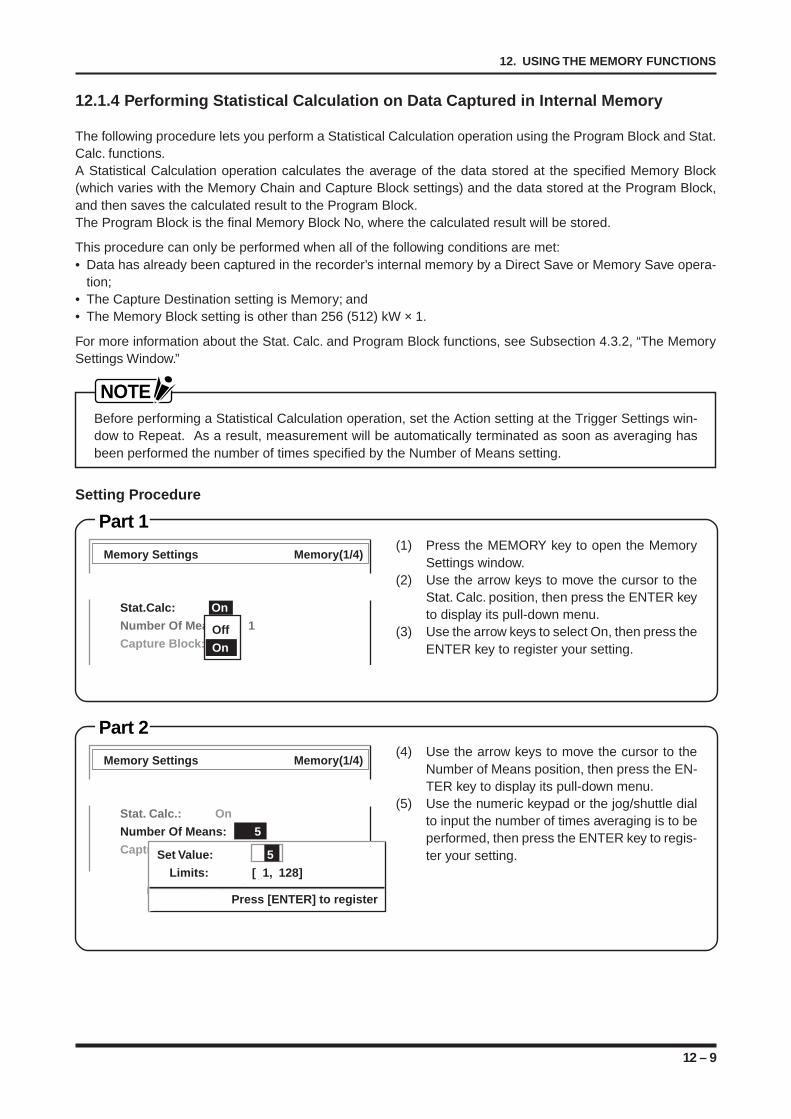
12 – 9
12. USING THE MEMORY FUNCTIONS
12.1.4 Performing Statistical Calculation on Data Captured in Internal Memory
The following procedure lets you perform a Statistical Calculation operation using the Program Block and Stat.Calc. functions.A Statistical Calculation operation calculates the average of the data stored at the specified Memory Block(which varies with the Memory Chain and Capture Block settings) and the data stored at the Program Block,and then saves the calculated result to the Program Block.The Program Block is the final Memory Block No, where the calculated result will be stored.
This procedure can only be performed when all of the following conditions are met:• Data has already been captured in the recorder’s internal memory by a Direct Save or Memory Save opera-
tion;• The Capture Destination setting is Memory; and• The Memory Block setting is other than 256 (512) kW × 1.
For more information about the Stat. Calc. and Program Block functions, see Subsection 4.3.2, “The MemorySettings Window.”
NOTEBefore performing a Statistical Calculation operation, set the Action setting at the Trigger Settings win-dow to Repeat. As a result, measurement will be automatically terminated as soon as averaging hasbeen performed the number of times specified by the Number of Means setting.
Setting Procedure
Part 1(1) Press the MEMORY key to open the Memory
Settings window.(2) Use the arrow keys to move the cursor to the
Stat. Calc. position, then press the ENTER keyto display its pull-down menu.
(3) Use the arrow keys to select On, then press theENTER key to register your setting.
Part 2(4) Use the arrow keys to move the cursor to the
Number of Means position, then press the EN-TER key to display its pull-down menu.
(5) Use the numeric keypad or the jog/shuttle dialto input the number of times averaging is to beperformed, then press the ENTER key to regis-ter your setting.
Memory Settings Memory(1/4)
Stat. Calc.: On
Number Of Means: 5
Capture Block: 9
1 2 3 4 5 6 7 8 9 10
Set Value: 5
Limits: [ 1, 128]
Press [ENTER] to register
Memory Settings Memory(1/4)
Stat.Calc: On
Number Of Means: 1
Capture Block: 9Off
On
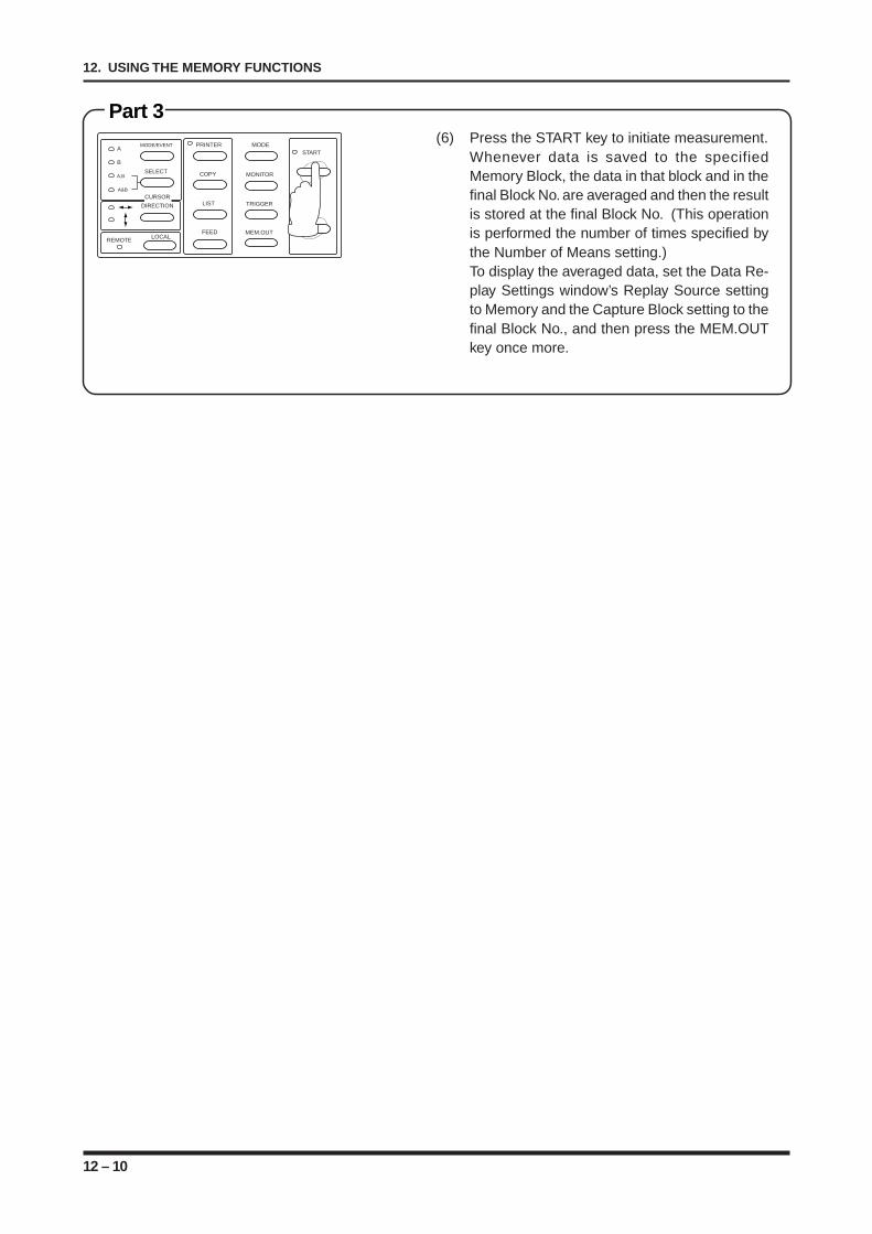
12 – 10
12. USING THE MEMORY FUNCTIONS
MODE/EVENT
SELECT
A
B
A,B
A&B
PRINTER
COPY
LIST
FEED
MODE
MONITOR
TRIGGER
MEM.OUT
START
STOP
LOCALREMOTE
CURSOR
DIRECTION
Part 3(6) Press the START key to initiate measurement.
Whenever data is saved to the specifiedMemory Block, the data in that block and in thefinal Block No. are averaged and then the resultis stored at the final Block No. (This operationis performed the number of times specified bythe Number of Means setting.)To display the averaged data, set the Data Re-play Settings window’s Replay Source settingto Memory and the Capture Block setting to thefinal Block No., and then press the MEM.OUTkey once more.
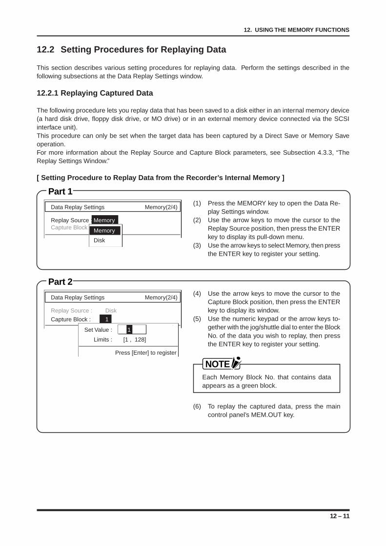
12 – 11
12. USING THE MEMORY FUNCTIONS
12.2 Setting Procedures for Replaying Data
This section describes various setting procedures for replaying data. Perform the settings described in thefollowing subsections at the Data Replay Settings window.
12.2.1 Replaying Captured Data
The following procedure lets you replay data that has been saved to a disk either in an internal memory device(a hard disk drive, floppy disk drive, or MO drive) or in an external memory device connected via the SCSIinterface unit).This procedure can only be set when the target data has been captured by a Direct Save or Memory Saveoperation.For more information about the Replay Source and Capture Block parameters, see Subsection 4.3.3, “TheReplay Settings Window.”
[ Setting Procedure to Replay Data from the Recorder’s Internal Memory ]
Data Replay Settings Memory(2/4)
Replay Source : MemoryCapture Block : Memory
Disk
Part 1(1) Press the MEMORY key to open the Data Re-
play Settings window.(2) Use the arrow keys to move the cursor to the
Replay Source position, then press the ENTERkey to display its pull-down menu.
(3) Use the arrow keys to select Memory, then pressthe ENTER key to register your setting.
Data Replay Settings Memory(2/4)
Replay Source : Disk
Capture Block : 1
Set Value : 1
Limits : [1 , 128]
Press [Enter] to register
Part 2(4) Use the arrow keys to move the cursor to the
Capture Block position, then press the ENTERkey to display its window.
(5) Use the numeric keypad or the arrow keys to-gether with the jog/shuttle dial to enter the BlockNo. of the data you wish to replay, then pressthe ENTER key to register your setting.
NOTEEach Memory Block No. that contains dataappears as a green block.
(6) To replay the captured data, press the maincontrol panel’s MEM.OUT key.
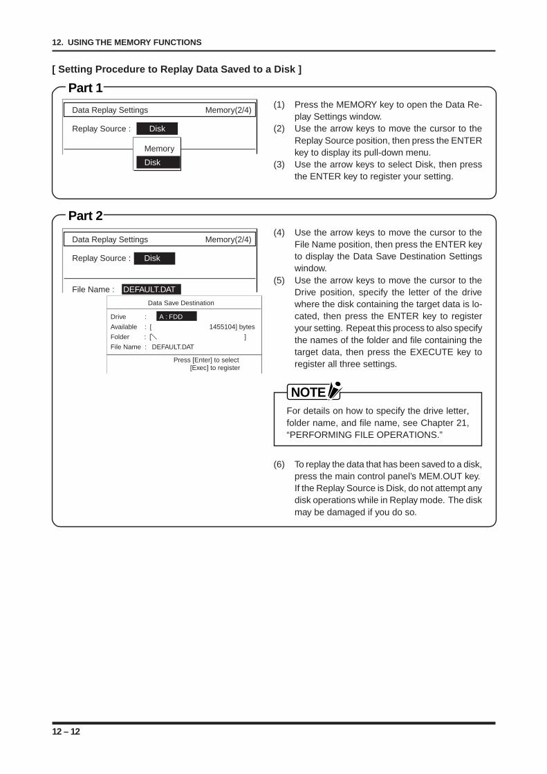
12 – 12
12. USING THE MEMORY FUNCTIONS
Part 1(1) Press the MEMORY key to open the Data Re-
play Settings window.(2) Use the arrow keys to move the cursor to the
Replay Source position, then press the ENTERkey to display its pull-down menu.
(3) Use the arrow keys to select Disk, then pressthe ENTER key to register your setting.
Part 2(4) Use the arrow keys to move the cursor to the
File Name position, then press the ENTER keyto display the Data Save Destination Settingswindow.
(5) Use the arrow keys to move the cursor to theDrive position, specify the letter of the drivewhere the disk containing the target data is lo-cated, then press the ENTER key to registeryour setting. Repeat this process to also specifythe names of the folder and file containing thetarget data, then press the EXECUTE key toregister all three settings.
NOTEFor details on how to specify the drive letter,folder name, and file name, see Chapter 21,“PERFORMING FILE OPERATIONS.”
(6) To replay the data that has been saved to a disk,press the main control panel’s MEM.OUT key.If the Replay Source is Disk, do not attempt anydisk operations while in Replay mode. The diskmay be damaged if you do so.
[ Setting Procedure to Replay Data Saved to a Disk ]
Data Replay Settings Memory(2/4)
Replay Source : Disk
Memory
Disk
Data Replay Settings Memory(2/4)
Replay Source : Disk
File Name : DEFAULT.DAT
Data Save Destination
Drive : A : FDD
Available : [ 1455104] bytes
Folder : [ ]
File Name : DEFAULT.DAT
Press [Enter] to select[Exec] to register
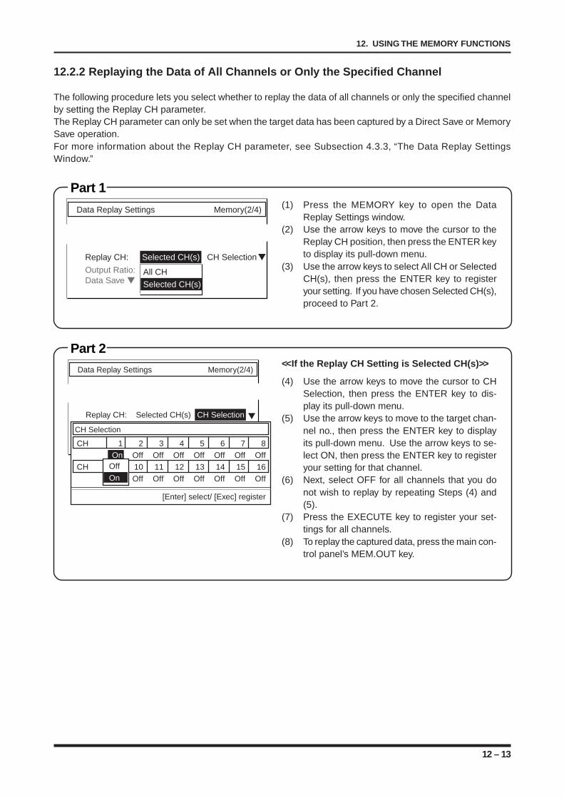
12 – 13
12. USING THE MEMORY FUNCTIONS
12.2.2 Replaying the Data of All Channels or Only the Specified Channel
The following procedure lets you select whether to replay the data of all channels or only the specified channelby setting the Replay CH parameter.The Replay CH parameter can only be set when the target data has been captured by a Direct Save or MemorySave operation.For more information about the Replay CH parameter, see Subsection 4.3.3, “The Data Replay SettingsWindow.”
Part 1(1) Press the MEMORY key to open the Data
Replay Settings window.(2) Use the arrow keys to move the cursor to the
Replay CH position, then press the ENTER keyto display its pull-down menu.
(3) Use the arrow keys to select All CH or SelectedCH(s), then press the ENTER key to registeryour setting. If you have chosen Selected CH(s),proceed to Part 2.
Part 2<<If the Replay CH Setting is Selected CH(s)>>
(4) Use the arrow keys to move the cursor to CHSelection, then press the ENTER key to dis-play its pull-down menu.
(5) Use the arrow keys to move to the target chan-nel no., then press the ENTER key to displayits pull-down menu. Use the arrow keys to se-lect ON, then press the ENTER key to registeryour setting for that channel.
(6) Next, select OFF for all channels that you donot wish to replay by repeating Steps (4) and(5).
(7) Press the EXECUTE key to register your set-tings for all channels.
(8) To replay the captured data, press the main con-trol panel’s MEM.OUT key.
Data Replay Settings Memory(2/4)
Replay CH: Selected CH(s) CH Selection
Output Ratio:Data Save
All CHSelected CH(s)
Data Replay Settings Memory(2/4)
Replay CH: Selected CH(s) CH Selection
CH 1 2 3 4 5 6 7 8
On Off Off Off Off Off Off Off
CH 9 10 11 12 13 14 15 16
Off Off Off Off Off Off Off Off
[Enter] select/ [Exec] register
CH Selection
Off
On
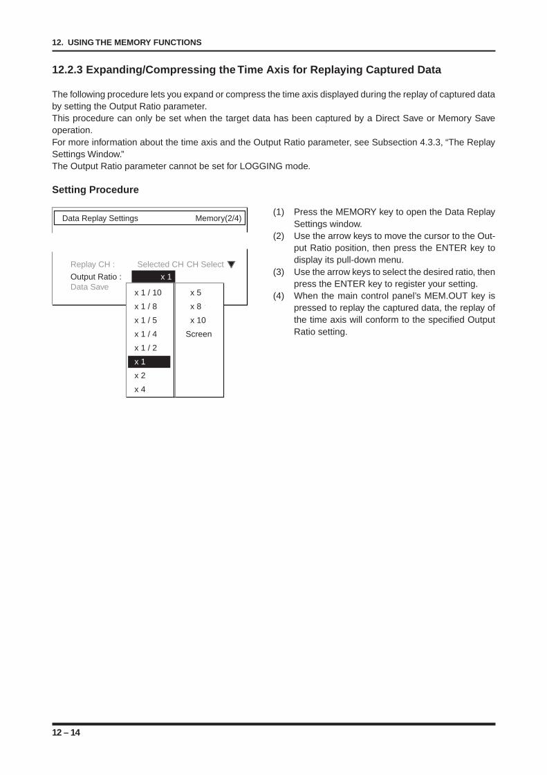
12 – 14
12. USING THE MEMORY FUNCTIONS
Data Replay Settings Memory(2/4)
Replay CH : Selected CH CH Select
Output Ratio : x 1Data Save
x 1 / 10 x 5
x 1 / 8 x 8
x 1 / 5 x 10
x 1 / 4 Screen
x 1 / 2
x 1
x 2
x 4
12.2.3 Expanding/Compressing the Time Axis for Replaying Captured Data
The following procedure lets you expand or compress the time axis displayed during the replay of captured databy setting the Output Ratio parameter.This procedure can only be set when the target data has been captured by a Direct Save or Memory Saveoperation.For more information about the time axis and the Output Ratio parameter, see Subsection 4.3.3, “The ReplaySettings Window.”The Output Ratio parameter cannot be set for LOGGING mode.
Setting Procedure
(1) Press the MEMORY key to open the Data ReplaySettings window.
(2) Use the arrow keys to move the cursor to the Out-put Ratio position, then press the ENTER key todisplay its pull-down menu.
(3) Use the arrow keys to select the desired ratio, thenpress the ENTER key to register your setting.
(4) When the main control panel’s MEM.OUT key ispressed to replay the captured data, the replay ofthe time axis will conform to the specified OutputRatio setting.
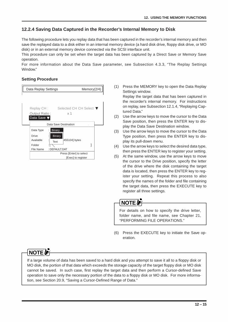
12 – 15
12. USING THE MEMORY FUNCTIONS
12.2.4 Saving Data Captured in the Recorder’s Internal Memory to Disk
The following procedure lets you replay data that has been captured in the recorder’s internal memory and thensave the replayed data to a disk either in an internal memory device (a hard disk drive, floppy disk drive, or MOdisk) or in an external memory device connected via the SCSI interface unit.This procedure can only be set when the target data has been captured by a Direct Save or Memory Saveoperation.For more information about the Data Save parameter, see Subsection 4.3.3, “The Replay SettingsWindow.”
Setting Procedure
(1) Press the MEMORY key to open the Data ReplaySettings window.Replay the target data that has been captured inthe recorder’s internal memory. For instructionson replay, see Subsection 12.1.4, “Replaying Cap-tured Data.”
(2) Use the arrow keys to move the cursor to the DataSave position, then press the ENTER key to dis-play the Data Save Destination window.
(3) Use the arrow keys to move the cursor to the DataType position, then press the ENTER key to dis-play its pull-down menu.
(4) Use the arrow keys to select the desired data type,then press the ENTER key to register your setting.
(5) At the same window, use the arrow keys to movethe cursor to the Drive position, specify the letterof the drive where the disk containing the targetdata is located, then press the ENTER key to reg-ister your setting. Repeat this process to alsospecify the names of the folder and file containingthe target data, then press the EXECUTE key toregister all three settings.
NOTEFor details on how to specify the drive letter,folder name, and file name, see Chapter 21,“PERFORMING FILE OPERATIONS.”
(6) Press the EXECUTE key to initiate the Save op-eration.
NOTEIf a large volume of data has been saved to a hard disk and you attempt to save it all to a floppy disk orMO disk, the portion of that data which exceeds the storage capacity of the target floppy disk or MO diskcannot be saved. In such case, first replay the target data and then perform a Cursor-defined Saveoperation to save only the necessary portion of the data to a floppy disk or MO disk. For more informa-tion, see Section 20.9, “Saving a Cursor-Defined Range of Data.”
Data Replay Settings Memory(2/4)
Replay CH : Selected CH CH Select
Output Ratio : x 1Data Save
Data Save Destination
Data Type : Binary
Drive : A : FDD
Available : [ 1455104] bytes
Folder : [ ]File Name : DEFAULT.DAT
Press [Enter] to select
[Exec] to register
Binary
Text
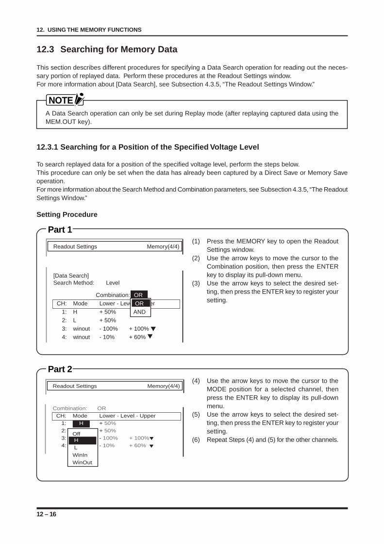
12 – 16
12. USING THE MEMORY FUNCTIONS
12.3 Searching for Memory Data
This section describes different procedures for specifying a Data Search operation for reading out the neces-sary portion of replayed data. Perform these procedures at the Readout Settings window.For more information about [Data Search], see Subsection 4.3.5, “The Readout Settings Window.”
NOTEA Data Search operation can only be set during Replay mode (after replaying captured data using theMEM.OUT key).
12.3.1 Searching for a Position of the Specified Voltage Level
To search replayed data for a position of the specified voltage level, perform the steps below.This procedure can only be set when the data has already been captured by a Direct Save or Memory Saveoperation.For more information about the Search Method and Combination parameters, see Subsection 4.3.5, “The ReadoutSettings Window.”
Setting Procedure
(1) Press the MEMORY key to open the ReadoutSettings window.
(2) Use the arrow keys to move the cursor to theCombination position, then press the ENTERkey to display its pull-down menu.
(3) Use the arrow keys to select the desired set-ting, then press the ENTER key to register yoursetting.
Part 1
Readout Settings Memory(4/4)
[Data Search]Search Method: Level
Combination: ORCH: Mode Lower - Level - Upper
1: H + 50%2: L + 50%3: winout - 100% + 100%4: winout - 10% + 60%
ORAND
Part 2(4) Use the arrow keys to move the cursor to the
MODE position for a selected channel, thenpress the ENTER key to display its pull-downmenu.
(5) Use the arrow keys to select the desired set-ting, then press the ENTER key to register yoursetting.
(6) Repeat Steps (4) and (5) for the other channels.
Readout Settings Memory(4/4)
Combination: ORCH: Mode Lower - Level - Upper
1: H + 50%2: H + 50%3: winout - 100% + 100%4: winout - 10% + 60%
Off H LWinInWinOut

12 – 17
12. USING THE MEMORY FUNCTIONS
Part 4(10) Press the main control panel’s MODE/EVENT
key to display the cursor.MODE/EVENT
SELECT
A
B
A,B
A&B
PRINTER
COPY
LIST
FEED
MODE
MONITOR
TRIGGER
MEM.OUT
START
STOP
LOCALREMOTE
CURSOR
DIRECTION
Part 5(11) Press the CLOSE key to close the Readout
Settings window.(12) Press the EXECUTE key to display the EX-
ECUTE menu.(13) Use the arrow keys to move the cursor to Next
Level Match or Prev. Level Match. When youpress the ENTER key, the recorder searchesthe position that satisfies the trigger conditionspecified under [Data Search] in the ReadoutSettings window, then displays that position onthe screen.
Execute Menu
[Serch]Next Level Match Prev. Level MatchNext Event Prev. Event
NOTEA regular Search operation can be performed by displaying the Execute menu and a simplifiedSearch operation can be performed using the and arrow keys. To perform a simplifiedSearch operation, complete Part 4 above and then either use the key to move to Next LevelMatch point or the key to move the Prev. Level Match point.Once an Event Search operation is performed from the Execute menu, the target of the simplifiedSearch operation becomes an Event. In this case, if you wish to perform a simplified Searchoperation for a target Level, return to the Execute menu and perform a Level Search operation.
(7) Use the arrow keys to move the cursor to theLower-Level-Upper position, then press theENTER key to display its window.
(8) Use the numeric keypad or the arrow keystogether with the jog/shuttle dial to enter thedesired level, then press the ENTER key to reg-ister your setting.
(9) Repeat Steps (7) and (8) for each of the otherchannels with a Mode setting of H, L, WinIn, orWinOut.
NOTE• If the Mode setting is Win In or Win Out, also
set the Lower Level and Upper Level values.• For details on inputting numeric values, see
Chapter 19, “INPUTTING ALPHANUMERICCHARACTERS.”
Part 3
Readout Settings Memory(4/4)
CH: Mode Lowe - Level - Upper1: H + 50%2: H + 50%3: winout - 100% + 100%4: winout - 10% + 60%5: H + 30%
Set Value : + 50Limits : [-100, +100]
Press [Enter] to register
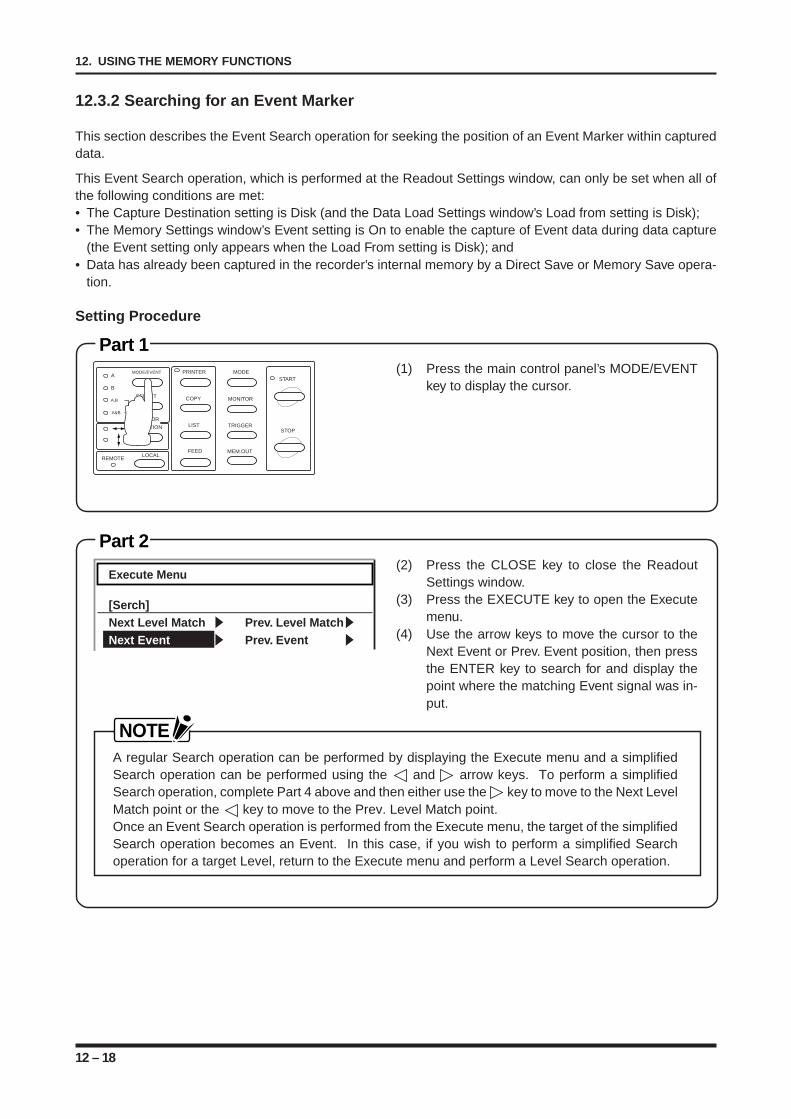
12 – 18
12. USING THE MEMORY FUNCTIONS
Part 2(2) Press the CLOSE key to close the Readout
Settings window.(3) Press the EXECUTE key to open the Execute
menu.(4) Use the arrow keys to move the cursor to the
Next Event or Prev. Event position, then pressthe ENTER key to search for and display thepoint where the matching Event signal was in-put.
Execute Menu
[Serch]Next Level Match Prev. Level MatchNext Event Prev. Event
Part 1(1) Press the main control panel’s MODE/EVENT
key to display the cursor.MODE/EVENT
SELECT
A
B
A,B
A&B
PRINTER
COPY
LIST
FEED
MODE
MONITOR
TRIGGER
MEM.OUT
START
STOP
LOCALREMOTE
CURSOR
DIRECTION
12.3.2 Searching for an Event Marker
This section describes the Event Search operation for seeking the position of an Event Marker within captureddata.
This Event Search operation, which is performed at the Readout Settings window, can only be set when all ofthe following conditions are met:• The Capture Destination setting is Disk (and the Data Load Settings window’s Load from setting is Disk);• The Memory Settings window’s Event setting is On to enable the capture of Event data during data capture
(the Event setting only appears when the Load From setting is Disk); and• Data has already been captured in the recorder’s internal memory by a Direct Save or Memory Save opera-
tion.
Setting Procedure
NOTEA regular Search operation can be performed by displaying the Execute menu and a simplifiedSearch operation can be performed using the and arrow keys. To perform a simplifiedSearch operation, complete Part 4 above and then either use the key to move to the Next LevelMatch point or the key to move to the Prev. Level Match point.Once an Event Search operation is performed from the Execute menu, the target of the simplifiedSearch operation becomes an Event. In this case, if you wish to perform a simplified Searchoperation for a target Level, return to the Execute menu and perform a Level Search operation.
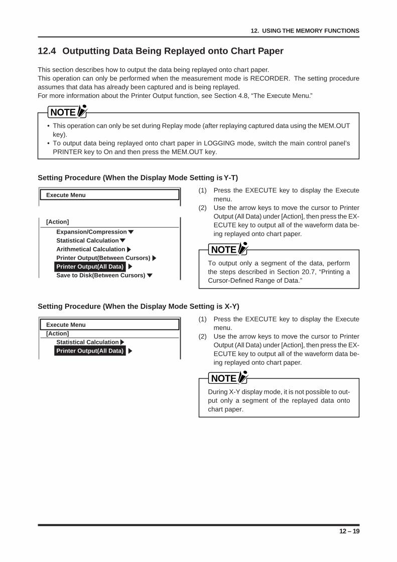
12 – 19
12. USING THE MEMORY FUNCTIONS
12.4 Outputting Data Being Replayed onto Chart Paper
This section describes how to output the data being replayed onto chart paper.This operation can only be performed when the measurement mode is RECORDER. The setting procedureassumes that data has already been captured and is being replayed.For more information about the Printer Output function, see Section 4.8, “The Execute Menu.”
NOTE• This operation can only be set during Replay mode (after replaying captured data using the MEM.OUT
key).• To output data being replayed onto chart paper in LOGGING mode, switch the main control panel’s
PRINTER key to On and then press the MEM.OUT key.
Setting Procedure (When the Display Mode Setting is Y-T)
(1) Press the EXECUTE key to display the Executemenu.
(2) Use the arrow keys to move the cursor to PrinterOutput (All Data) under [Action], then press the EX-ECUTE key to output all of the waveform data be-ing replayed onto chart paper.
NOTETo output only a segment of the data, performthe steps described in Section 20.7, “Printing aCursor-Defined Range of Data.”
Setting Procedure (When the Display Mode Setting is X-Y)
(1) Press the EXECUTE key to display the Executemenu.
(2) Use the arrow keys to move the cursor to PrinterOutput (All Data) under [Action], then press the EX-ECUTE key to output all of the waveform data be-ing replayed onto chart paper.
NOTEDuring X-Y display mode, it is not possible to out-put only a segment of the replayed data ontochart paper.
Execute Menu
[Action]
Expansion/CompressionStatistical CalculationArithmetical CalculationPrinter Output(Between Cursors)Printer Output(All Data)Save to Disk(Between Cursors)
Execute Menu[Action]
Statistical CalculationPrinter Output(All Data)
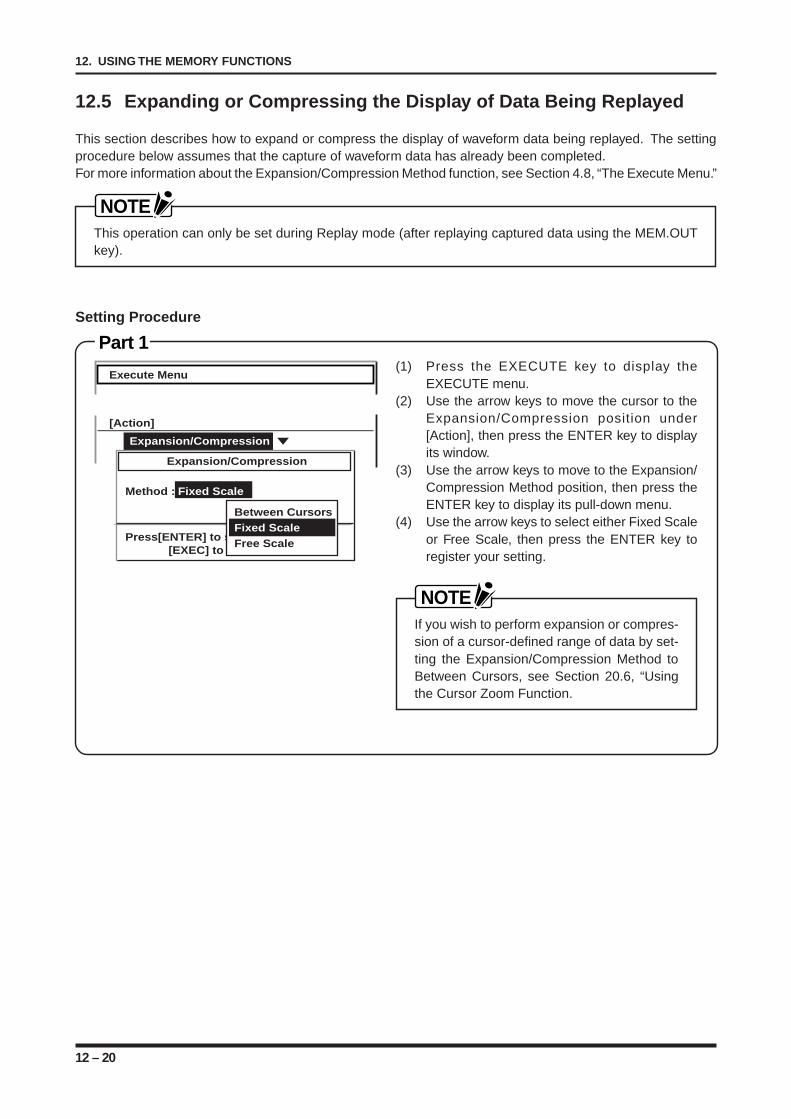
12 – 20
12. USING THE MEMORY FUNCTIONS
Execute Menu
[Action]
Expansion/CompressionStatistical CalculationExpansion/Compression
Method : Fixed Scale
Press[ENTER] to select[EXEC] to execute
Between CursorsFixed ScaleFree Scale
12.5 Expanding or Compressing the Display of Data Being Replayed
This section describes how to expand or compress the display of waveform data being replayed. The settingprocedure below assumes that the capture of waveform data has already been completed.For more information about the Expansion/Compression Method function, see Section 4.8, “The Execute Menu.”
NOTEThis operation can only be set during Replay mode (after replaying captured data using the MEM.OUTkey).
Setting Procedure
Part 1(1) Press the EXECUTE key to display the
EXECUTE menu.(2) Use the arrow keys to move the cursor to the
Expansion/Compression position under[Action], then press the ENTER key to displayits window.
(3) Use the arrow keys to move to the Expansion/Compression Method position, then press theENTER key to display its pull-down menu.
(4) Use the arrow keys to select either Fixed Scaleor Free Scale, then press the ENTER key toregister your setting.
NOTEIf you wish to perform expansion or compres-sion of a cursor-defined range of data by set-ting the Expansion/Compression Method toBetween Cursors, see Section 20.6, “Usingthe Cursor Zoom Function.
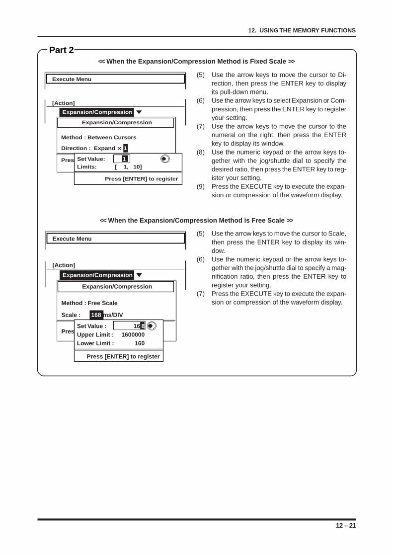
12 – 21
12. USING THE MEMORY FUNCTIONS
<< When the Expansion/Compression Method is Fixed Scale >>
(5) Use the arrow keys to move the cursor to Scale,then press the ENTER key to display its win-dow.
(6) Use the numeric keypad or the arrow keys to-gether with the jog/shuttle dial to specify a mag-nification ratio, then press the ENTER key toregister your setting.
(7) Press the EXECUTE key to execute the expan-sion or compression of the waveform display.
<< When the Expansion/Compression Method is Free Scale >>
Part 2
(5) Use the arrow keys to move the cursor to Di-rection, then press the ENTER key to displayits pull-down menu.
(6) Use the arrow keys to select Expansion or Com-pression, then press the ENTER key to registeryour setting.
(7) Use the arrow keys to move the cursor to thenumeral on the right, then press the ENTERkey to display its window.
(8) Use the numeric keypad or the arrow keys to-gether with the jog/shuttle dial to specify thedesired ratio, then press the ENTER key to reg-ister your setting.
(9) Press the EXECUTE key to execute the expan-sion or compression of the waveform display.
Execute Menu
[Action]
Expansion/CompressionStatistical CalculationExpansion/Compression
Method : Between Cursors
Direction : Expand 1
Press[ENTER] to select[EXEC] to execute
Set Value: 1Limits: [ 1, 10]
Press [ENTER] to register
Execute Menu
[Action]
Expansion/CompressionStatistical CalculationExpansion/Compression
Method : Free Scale
Scale : 168 ms/DIV 1
Press[ENTER] t: select[EXEC] to execute
Set Value : 16 8Upper Limit : 1600000Lower Limit : 160
Press [ENTER] to register
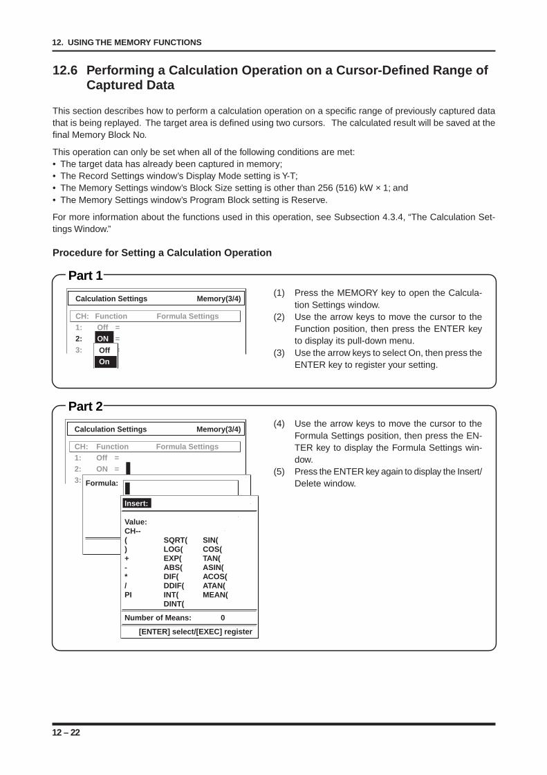
12 – 22
12. USING THE MEMORY FUNCTIONS
Calculation Settings Memory(3/4)
CH: Function Formula Settings1: Off =2: ON =3: On =Formula:
[ENTER] select / [Exec] register
Insert:
Value:CH--( SQRT( SIN() LOG( COS(+ EXP( TAN(- ABS( ASIN(* DIF( ACOS(/ DDIF( ATAN(PI INT( MEAN(
DINT(
Number of Means: 0
[ENTER] select/[EXEC] register
Calculation Settings Memory(3/4)
CH: Function Formula Settings1: Off =2: ON =3: On =Off
On
12.6 Performing a Calculation Operation on a Cursor-Defined Range ofCaptured Data
This section describes how to perform a calculation operation on a specific range of previously captured datathat is being replayed. The target area is defined using two cursors. The calculated result will be saved at thefinal Memory Block No.
This operation can only be set when all of the following conditions are met:• The target data has already been captured in memory;• The Record Settings window’s Display Mode setting is Y-T;• The Memory Settings window’s Block Size setting is other than 256 (516) kW × 1; and• The Memory Settings window’s Program Block setting is Reserve.
For more information about the functions used in this operation, see Subsection 4.3.4, “The Calculation Set-tings Window.”
Procedure for Setting a Calculation Operation
(1) Press the MEMORY key to open the Calcula-tion Settings window.
(2) Use the arrow keys to move the cursor to theFunction position, then press the ENTER keyto display its pull-down menu.
(3) Use the arrow keys to select On, then press theENTER key to register your setting.
Part 1
(4) Use the arrow keys to move the cursor to theFormula Settings position, then press the EN-TER key to display the Formula Settings win-dow.
(5) Press the ENTER key again to display the Insert/Delete window.
Part 2
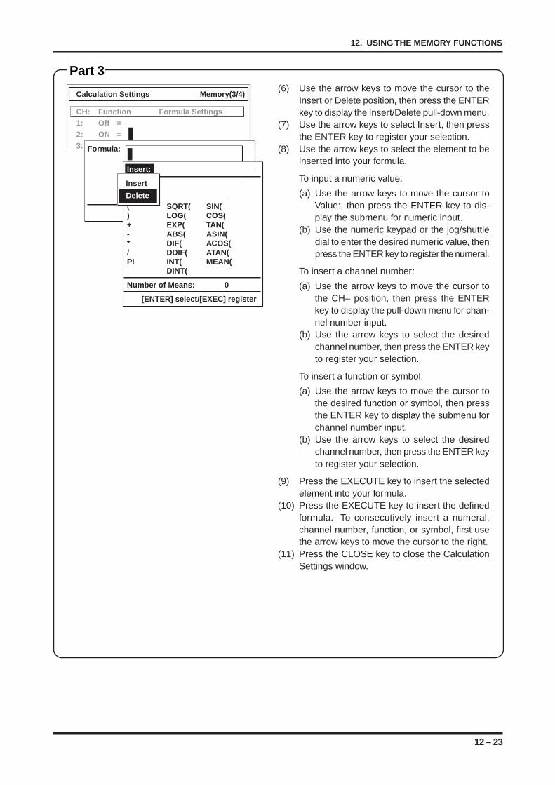
12 – 23
12. USING THE MEMORY FUNCTIONS
(6) Use the arrow keys to move the cursor to theInsert or Delete position, then press the ENTERkey to display the Insert/Delete pull-down menu.
(7) Use the arrow keys to select Insert, then pressthe ENTER key to register your selection.
(8) Use the arrow keys to select the element to beinserted into your formula.
To input a numeric value:
(a) Use the arrow keys to move the cursor toValue:, then press the ENTER key to dis-play the submenu for numeric input.
(b) Use the numeric keypad or the jog/shuttledial to enter the desired numeric value, thenpress the ENTER key to register the numeral.
To insert a channel number:
(a) Use the arrow keys to move the cursor tothe CH– position, then press the ENTERkey to display the pull-down menu for chan-nel number input.
(b) Use the arrow keys to select the desiredchannel number, then press the ENTER keyto register your selection.
To insert a function or symbol:
(a) Use the arrow keys to move the cursor tothe desired function or symbol, then pressthe ENTER key to display the submenu forchannel number input.
(b) Use the arrow keys to select the desiredchannel number, then press the ENTER keyto register your selection.
(9) Press the EXECUTE key to insert the selectedelement into your formula.
(10) Press the EXECUTE key to insert the definedformula. To consecutively insert a numeral,channel number, function, or symbol, first usethe arrow keys to move the cursor to the right.
(11) Press the CLOSE key to close the CalculationSettings window.
Part 3
Calculation Settings Memory(3/4)
CH: Function Formula Settings1: Off =2: ON =3: On =Formula:
[ENTER] select / [Exec] register
Insert:
Value:CH--( SQRT( SIN() LOG( COS(+ EXP( TAN(- ABS( ASIN(* DIF( ACOS(/ DDIF( ATAN(PI INT( MEAN(
DINT(
Number of Means: 0
[ENTER] select/[EXEC] register
Insert
Delete
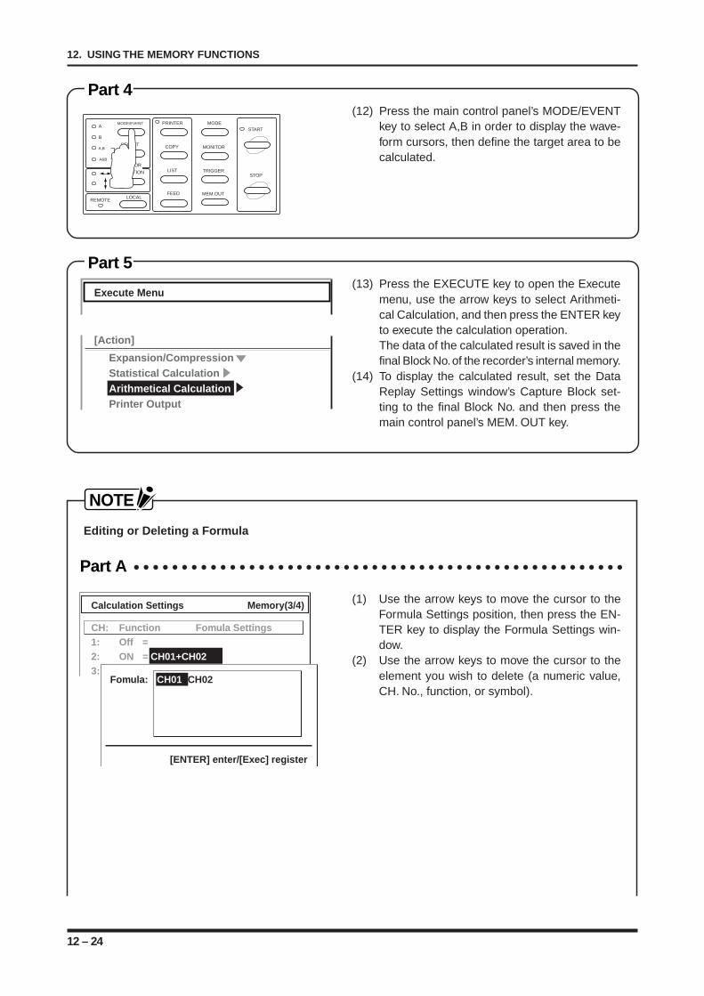
12 – 24
12. USING THE MEMORY FUNCTIONS
Part 4(12) Press the main control panel’s MODE/EVENT
key to select A,B in order to display the wave-form cursors, then define the target area to becalculated.
MODE/EVENT
SELECT
A
B
A,B
A&B
PRINTER
COPY
LIST
FEED
MODE
MONITOR
TRIGGER
MEM.OUT
START
STOP
LOCALREMOTE
CURSOR
DIRECTION
Part 5(13) Press the EXECUTE key to open the Execute
menu, use the arrow keys to select Arithmeti-cal Calculation, and then press the ENTER keyto execute the calculation operation.The data of the calculated result is saved in thefinal Block No. of the recorder’s internal memory.
(14) To display the calculated result, set the DataReplay Settings window’s Capture Block set-ting to the final Block No. and then press themain control panel’s MEM. OUT key.
NOTE
Editing or Deleting a Formula
Part A
(1) Use the arrow keys to move the cursor to theFormula Settings position, then press the EN-TER key to display the Formula Settings win-dow.
(2) Use the arrow keys to move the cursor to theelement you wish to delete (a numeric value,CH. No., function, or symbol).
Execute Menu
[Action]
Expansion/CompressionStatistical CalculationArithmetical CalculationPrinter Output
Calculation Settings Memory(3/4)
CH: Function Fomula Settings1: Off =2: ON = CH01+CH023: On =
Fomula: CH01+CH02
[ENTER] enter/[Exec] register
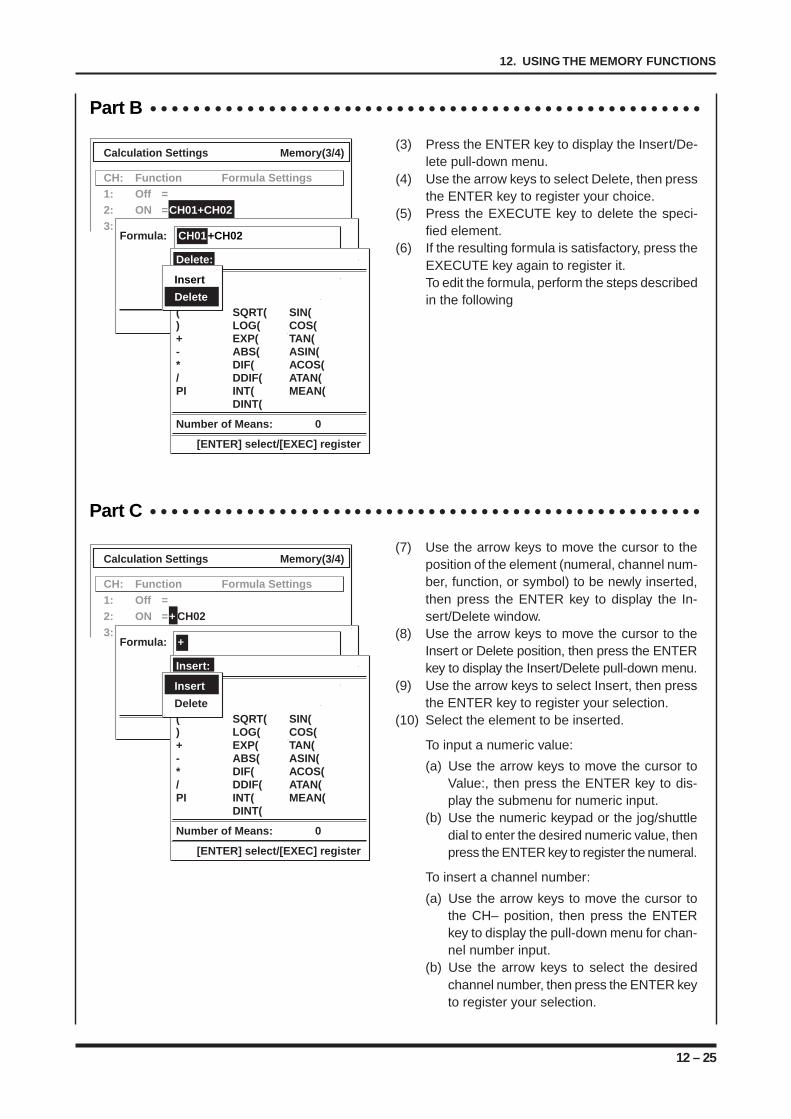
12 – 25
12. USING THE MEMORY FUNCTIONS
Part C
(7) Use the arrow keys to move the cursor to theposition of the element (numeral, channel num-ber, function, or symbol) to be newly inserted,then press the ENTER key to display the In-sert/Delete window.
(8) Use the arrow keys to move the cursor to theInsert or Delete position, then press the ENTERkey to display the Insert/Delete pull-down menu.
(9) Use the arrow keys to select Insert, then pressthe ENTER key to register your selection.
(10) Select the element to be inserted.
To input a numeric value:
(a) Use the arrow keys to move the cursor toValue:, then press the ENTER key to dis-play the submenu for numeric input.
(b) Use the numeric keypad or the jog/shuttledial to enter the desired numeric value, thenpress the ENTER key to register the numeral.
To insert a channel number:
(a) Use the arrow keys to move the cursor tothe CH– position, then press the ENTERkey to display the pull-down menu for chan-nel number input.
(b) Use the arrow keys to select the desiredchannel number, then press the ENTER keyto register your selection.
Calculation Settings Memory(3/4)
CH: Function Formula Settings1: Off =2: ON = + CH023: On =
Formula: +
[ENTER] select / [Exec] register
Insert:
Value:CH--( SQRT( SIN() LOG( COS(+ EXP( TAN(- ABS( ASIN(* DIF( ACOS(/ DDIF( ATAN(PI INT( MEAN(
DINT(
Number of Means: 0
[ENTER] select/[EXEC] register
Insert
Delete
Part B
(3) Press the ENTER key to display the Insert/De-lete pull-down menu.
(4) Use the arrow keys to select Delete, then pressthe ENTER key to register your choice.
(5) Press the EXECUTE key to delete the speci-fied element.
(6) If the resulting formula is satisfactory, press theEXECUTE key again to register it.To edit the formula, perform the steps describedin the following
Calculation Settings Memory(3/4)
CH: Function Formula Settings1: Off =2: ON = CH01+CH023: On =
Formula: CH01+CH02
[ENTER] select / [Exec] register
Delete:
Value:CH--( SQRT( SIN() LOG( COS(+ EXP( TAN(- ABS( ASIN(* DIF( ACOS(/ DDIF( ATAN(PI INT( MEAN(
DINT(
Number of Means: 0
[ENTER] select/[EXEC] register
Insert
Delete
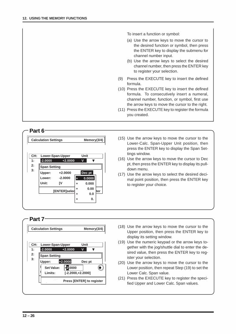
12 – 26
12. USING THE MEMORY FUNCTIONS
To insert a function or symbol:
(a) Use the arrow keys to move the cursor tothe desired function or symbol, then pressthe ENTER key to display the submenu forchannel number input.
(b) Use the arrow keys to select the desiredchannel number, then press the ENTER keyto register your selection.
(9) Press the EXECUTE key to insert the definedformula.
(10) Press the EXECUTE key to insert the definedformula. To consecutively insert a numeral,channel number, function, or symbol, first usethe arrow keys to move the cursor to the right.
(11) Press the EXECUTE key to register the formulayou created.
(15) Use the arrow keys to move the cursor to theLower-Calc. Span-Upper Unit position, thenpress the ENTER key to display the Span Set-tings window.
(16) Use the arrow keys to move the cursor to Decpt, then press the ENTER key to display its pull-down menu.
(17) Use the arrow keys to select the desired deci-mal point position, then press the ENTER keyto register your choice.
Part 6
Calculation Settings Memory(3/4)
CH: Lower-Span-Upper Unit1: -2.0000 +2.0000 V2: -100.00 +100.00 mV3: -2.0000 +2.0000 V
Span Setting
Upper: +2.0000 Dec pt
Lower: -2.0000
Unit: [V ]
[ENTER]select/[EXEC]register
Set Value: +2.0000
Limits: [-2.2000,+2.2000]
Press [ENTER] to register
Calculation Settings Memory(3/4)
CH: Lower-Span-Upper Unit1: -2.0000 +2.0000 V2: -100.00 +100.00 mV3: -2.0000 +2.0000 V
Span Setting
Upper: +2.0000 Dec pt
Lower: -2.0000
Unit: [V ]
[ENTER]select/[EXEC]register
+ 0.0000
+ 0.000
+ 0.00
+ 0.0
+ 0.
(18) Use the arrow keys to move the cursor to theUpper position, then press the ENTER key todisplay its setting window.
(19) Use the numeric keypad or the arrow keys to-gether with the jog/shuttle dial to enter the de-sired value, then press the ENTER key to reg-ister your selection.
(20) Use the arrow keys to move the cursor to theLower position, then repeat Step (19) to set theLower Calc. Span value.
(21) Press the EXECUTE key to register the speci-fied Upper and Lower Calc. Span values.
Part 7
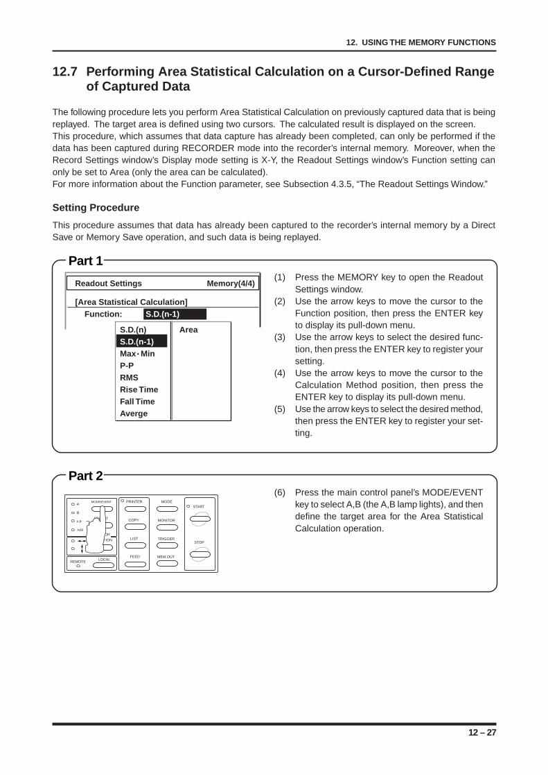
12 – 27
12. USING THE MEMORY FUNCTIONS
12.7 Performing Area Statistical Calculation on a Cursor-Defined Rangeof Captured Data
The following procedure lets you perform Area Statistical Calculation on previously captured data that is beingreplayed. The target area is defined using two cursors. The calculated result is displayed on the screen.This procedure, which assumes that data capture has already been completed, can only be performed if thedata has been captured during RECORDER mode into the recorder’s internal memory. Moreover, when theRecord Settings window’s Display mode setting is X-Y, the Readout Settings window’s Function setting canonly be set to Area (only the area can be calculated).For more information about the Function parameter, see Subsection 4.3.5, “The Readout Settings Window.”
Setting Procedure
This procedure assumes that data has already been captured to the recorder’s internal memory by a DirectSave or Memory Save operation, and such data is being replayed.
Part 1(1) Press the MEMORY key to open the Readout
Settings window.(2) Use the arrow keys to move the cursor to the
Function position, then press the ENTER keyto display its pull-down menu.
(3) Use the arrow keys to select the desired func-tion, then press the ENTER key to register yoursetting.
(4) Use the arrow keys to move the cursor to theCalculation Method position, then press theENTER key to display its pull-down menu.
(5) Use the arrow keys to select the desired method,then press the ENTER key to register your set-ting.
Readout Settings Memory(4/4)
[Area Statistical Calculation]Function: S.D.(n-1)
S.D.(n) AreaS.D.(n-1)Max MinP-PRMSRise TimeFall TimeAverge
Part 2(6) Press the main control panel’s MODE/EVENT
key to select A,B (the A,B lamp lights), and thendefine the target area for the Area StatisticalCalculation operation.
MODE/EVENT
SELECT
A
B
A,B
A&B
PRINTER
COPY
LIST
FEED
MODE
MONITOR
TRIGGER
MEM.OUT
START
STOP
LOCALREMOTE
CURSOR
DIRECTION

12 – 28
12. USING THE MEMORY FUNCTIONS
Part 3(7) Press the EXECUTE key to open the Execute
menu. Next, use the arrow keys to select Sta-tistical Calculation and press the ENTER keyto execute the specified operation.After the calculation is completed, the calculatedresult is displayed on the screen.
Execute Menu
[Action]
Expansion/CompressionStatistical CalculationArithmetical CalculationPrinter Output
13 – 1
13. USING THE TRIGGER FUNCTIONS
CHAPTER 13CHAPTER 13USING THE TRIGGER FUNCTIONS
This chapter describes the overall flow of setting param-eters related to trigger operations.
13.1 Disabling the Trigger Function13.2 Activating the Trigger by the TRIGGER Key13.3 Activating the Trigger by an Externally-Supplied
REMOTE Signal13.4 Activating the Trigger by the Signal Input’s Voltage
Level13.4.1 Starting/Stopping Measurement When the Trigger
Condition of One Channel Is Met13.4.2 Starting/Stopping Measurement When the Trigger
Condition of Every Channel Is Met13.5 Activating the Trigger by the Slope of the Signal
Input’s Rise (Fall) Time13.6 Arming the Trigger Only within the Specified Time
Interval13.7 Starting Measurement Before (After) the Trigger Is
Activated13.8 Stopping Measurement at a Specified Time Interval
After the Trigger is Activated13.9 Starting/Stopping Measurement After the Trigger Is
Activated the Specified Number of Times13.10 Filtering the Trigger
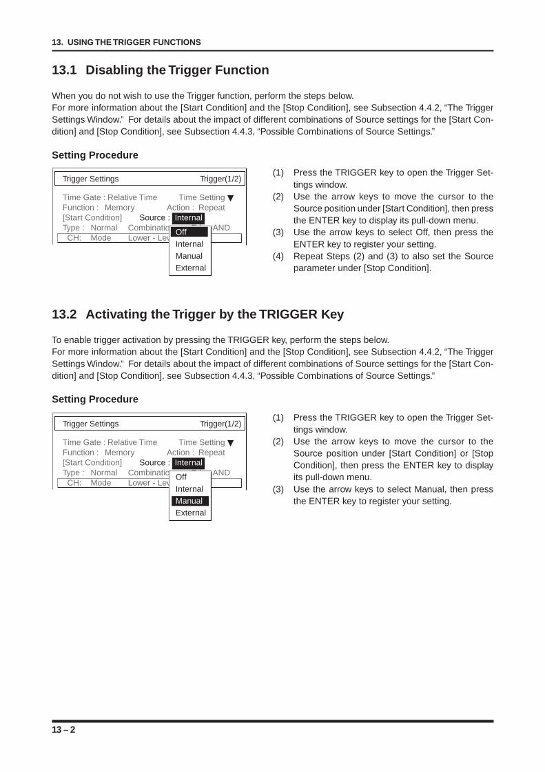
13 – 2
13. USING THE TRIGGER FUNCTIONS
13.1 Disabling the Trigger Function
When you do not wish to use the Trigger function, perform the steps below.For more information about the [Start Condition] and the [Stop Condition], see Subsection 4.4.2, “The TriggerSettings Window.” For details about the impact of different combinations of Source settings for the [Start Con-dition] and [Stop Condition], see Subsection 4.4.3, “Possible Combinations of Source Settings.”
Setting Procedure
Trigger Settings Trigger(1/2)
Time Gate : Relative Time Time SettingFunction : Memory Action : Repeat[Start Condition] Source : InternalType : Normal Combination : Edge AND
CH: Mode Lower - Level - UpperOffInternalManualExternal
Trigger Settings Trigger(1/2)
Time Gate : Relative Time Time SettingFunction : Memory Action : Repeat[Start Condition] Source : InternalType : Normal Combination : Edge AND
CH: Mode Lower - Level - UpperOffInternalManualExternal
(1) Press the TRIGGER key to open the Trigger Set-tings window.
(2) Use the arrow keys to move the cursor to theSource position under [Start Condition], then pressthe ENTER key to display its pull-down menu.
(3) Use the arrow keys to select Off, then press theENTER key to register your setting.
(4) Repeat Steps (2) and (3) to also set the Sourceparameter under [Stop Condition].
13.2 Activating the Trigger by the TRIGGER Key
To enable trigger activation by pressing the TRIGGER key, perform the steps below.For more information about the [Start Condition] and the [Stop Condition], see Subsection 4.4.2, “The TriggerSettings Window.” For details about the impact of different combinations of Source settings for the [Start Con-dition] and [Stop Condition], see Subsection 4.4.3, “Possible Combinations of Source Settings.”
Setting Procedure
(1) Press the TRIGGER key to open the Trigger Set-tings window.
(2) Use the arrow keys to move the cursor to theSource position under [Start Condition] or [StopCondition], then press the ENTER key to displayits pull-down menu.
(3) Use the arrow keys to select Manual, then pressthe ENTER key to register your setting.
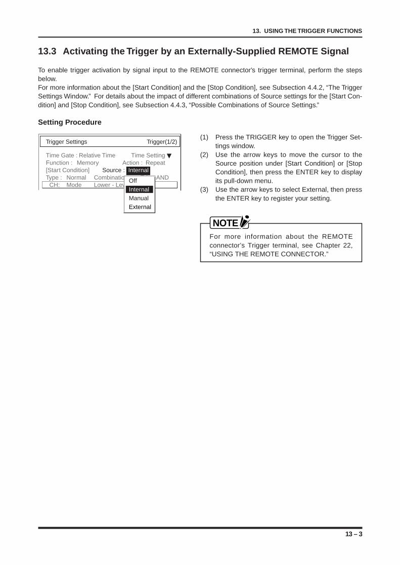
13 – 3
13. USING THE TRIGGER FUNCTIONS
Trigger Settings Trigger(1/2)
Time Gate : Relative Time Time SettingFunction : Memory Action : Repeat[Start Condition] Source : InternalType : Normal Combination : Edge AND
CH: Mode Lower - Level - UpperOffInternalManualExternal
13.3 Activating the Trigger by an Externally-Supplied REMOTE Signal
To enable trigger activation by signal input to the REMOTE connector’s trigger terminal, perform the stepsbelow.For more information about the [Start Condition] and the [Stop Condition], see Subsection 4.4.2, “The TriggerSettings Window.” For details about the impact of different combinations of Source settings for the [Start Con-dition] and [Stop Condition], see Subsection 4.4.3, “Possible Combinations of Source Settings.”
Setting Procedure
(1) Press the TRIGGER key to open the Trigger Set-tings window.
(2) Use the arrow keys to move the cursor to theSource position under [Start Condition] or [StopCondition], then press the ENTER key to displayits pull-down menu.
(3) Use the arrow keys to select External, then pressthe ENTER key to register your setting.
NOTEFor more information about the REMOTEconnector’s Trigger terminal, see Chapter 22,“USING THE REMOTE CONNECTOR.”
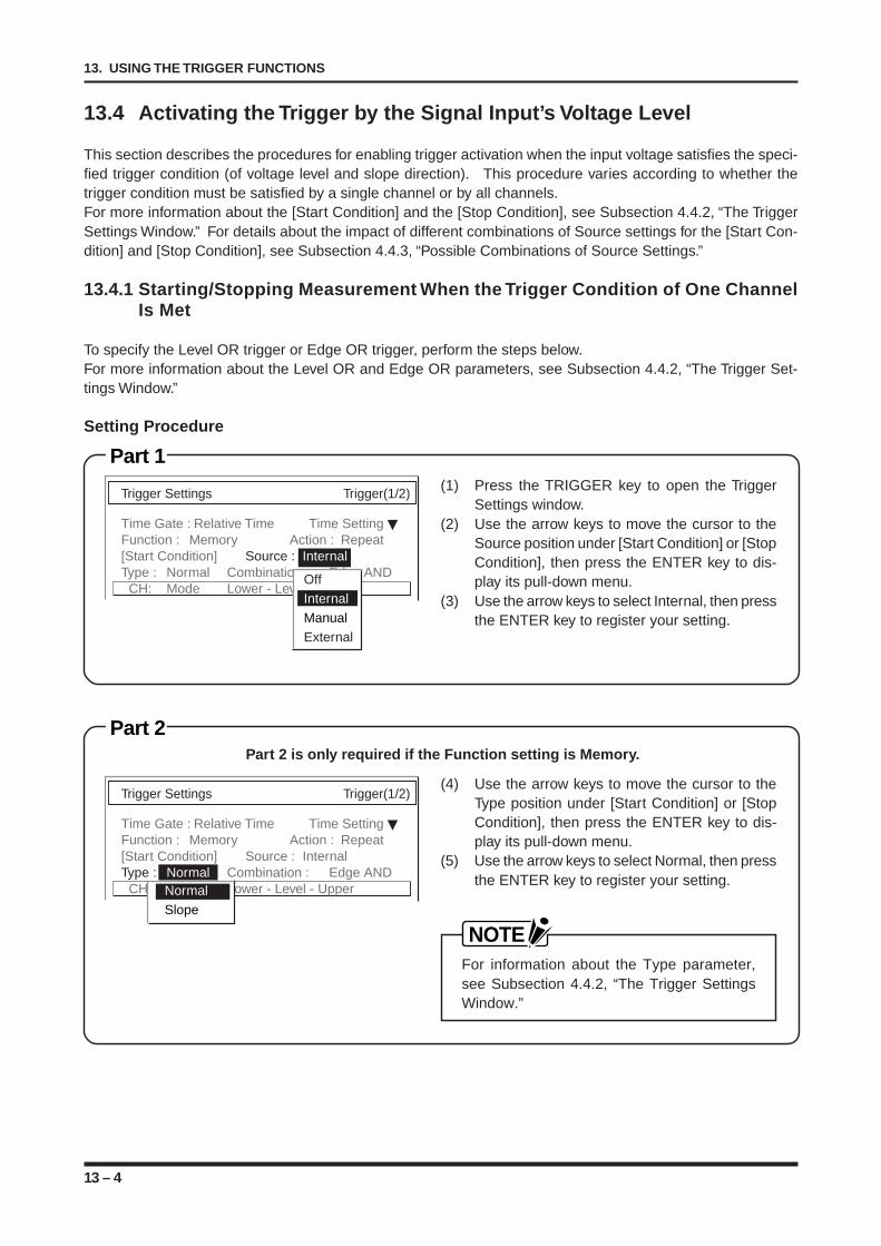
13 – 4
13. USING THE TRIGGER FUNCTIONS
Part 1
Part 2
Trigger Settings Trigger(1/2)
Time Gate : Relative Time Time SettingFunction : Memory Action : Repeat[Start Condition] Source : InternalType : Normal Combination : Edge AND
CH: Mode Lower - Level - UpperOffInternalManualExternal
13.4 Activating the Trigger by the Signal Input’s Voltage Level
This section describes the procedures for enabling trigger activation when the input voltage satisfies the speci-fied trigger condition (of voltage level and slope direction). This procedure varies according to whether thetrigger condition must be satisfied by a single channel or by all channels.For more information about the [Start Condition] and the [Stop Condition], see Subsection 4.4.2, “The TriggerSettings Window.” For details about the impact of different combinations of Source settings for the [Start Con-dition] and [Stop Condition], see Subsection 4.4.3, “Possible Combinations of Source Settings.”
13.4.1 Starting/Stopping Measurement When the Trigger Condition of One ChannelIs Met
To specify the Level OR trigger or Edge OR trigger, perform the steps below.For more information about the Level OR and Edge OR parameters, see Subsection 4.4.2, “The Trigger Set-tings Window.”
Setting Procedure
(4) Use the arrow keys to move the cursor to theType position under [Start Condition] or [StopCondition], then press the ENTER key to dis-play its pull-down menu.
(5) Use the arrow keys to select Normal, then pressthe ENTER key to register your setting.
NOTEFor information about the Type parameter,see Subsection 4.4.2, “The Trigger SettingsWindow.”
Part 2 is only required if the Function setting is Memory.
Trigger Settings Trigger(1/2)
Time Gate : Relative Time Time SettingFunction : Memory Action : Repeat[Start Condition] Source : InternalType : Normal Combination : Edge AND
CH: Mode Lower - Level - UpperNormalSlope
(1) Press the TRIGGER key to open the TriggerSettings window.
(2) Use the arrow keys to move the cursor to theSource position under [Start Condition] or [StopCondition], then press the ENTER key to dis-play its pull-down menu.
(3) Use the arrow keys to select Internal, then pressthe ENTER key to register your setting.
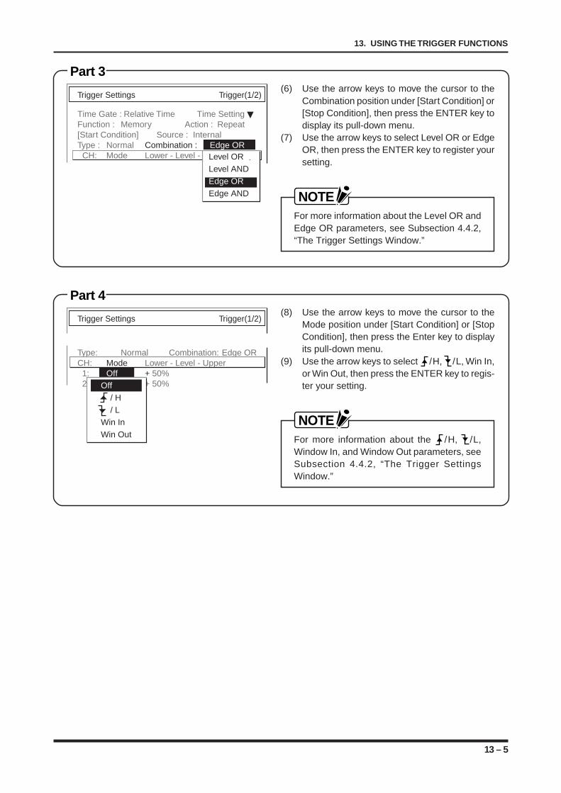
13 – 5
13. USING THE TRIGGER FUNCTIONS
Part 3
Part 4
Trigger Settings Trigger(1/2)
Time Gate : Relative Time Time SettingFunction : Memory Action : Repeat[Start Condition] Source : InternalType : Normal Combination : Edge OR
CH: Mode Lower - Level - UpperLevel ORLevel ANDEdge OREdge AND
Trigger Settings Trigger(1/2)
Type: Normal Combination: Edge ORCH: Mode Lower - Level - Upper 1: Off + 50% 2: Off + 50%Off
/ H / LWin InWin Out
(6) Use the arrow keys to move the cursor to theCombination position under [Start Condition] or[Stop Condition], then press the ENTER key todisplay its pull-down menu.
(7) Use the arrow keys to select Level OR or EdgeOR, then press the ENTER key to register yoursetting.
NOTEFor more information about the Level OR andEdge OR parameters, see Subsection 4.4.2,“The Trigger Settings Window.”
(8) Use the arrow keys to move the cursor to theMode position under [Start Condition] or [StopCondition], then press the Enter key to displayits pull-down menu.
(9) Use the arrow keys to select /H, /L, Win In,or Win Out, then press the ENTER key to regis-ter your setting.
NOTEFor more information about the /H, /L,Window In, and Window Out parameters, seeSubsection 4.4.2, “The Trigger SettingsWindow.”
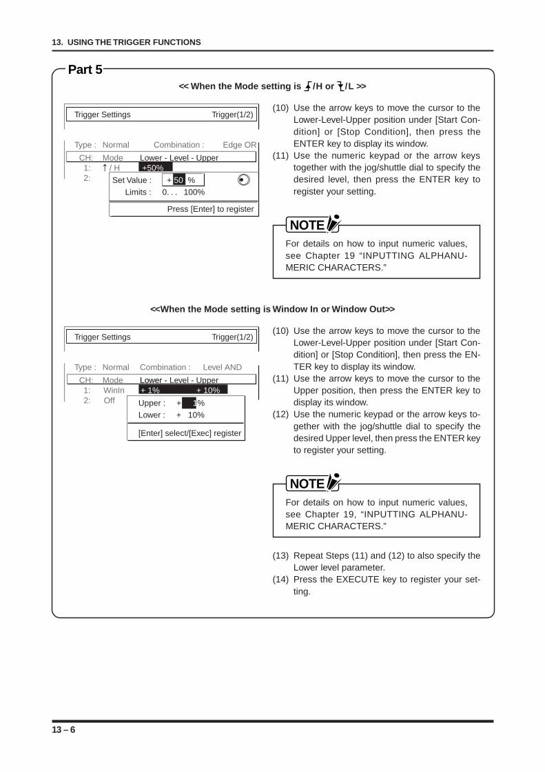
13 – 6
13. USING THE TRIGGER FUNCTIONS
Part 5
(10) Use the arrow keys to move the cursor to theLower-Level-Upper position under [Start Con-dition] or [Stop Condition], then press theENTER key to display its window.
(11) Use the numeric keypad or the arrow keystogether with the jog/shuttle dial to specify thedesired level, then press the ENTER key toregister your setting.
NOTEFor details on how to input numeric values,see Chapter 19 “INPUTTING ALPHANU-MERIC CHARACTERS.”
<< When the Mode setting is /H or /L >>
(10) Use the arrow keys to move the cursor to theLower-Level-Upper position under [Start Con-dition] or [Stop Condition], then press the EN-TER key to display its window.
(11) Use the arrow keys to move the cursor to theUpper position, then press the ENTER key todisplay its window.
(12) Use the numeric keypad or the arrow keys to-gether with the jog/shuttle dial to specify thedesired Upper level, then press the ENTER keyto register your setting.
NOTEFor details on how to input numeric values,see Chapter 19, “INPUTTING ALPHANU-MERIC CHARACTERS.”
(13) Repeat Steps (11) and (12) to also specify theLower level parameter.
(14) Press the EXECUTE key to register your set-ting.
<<When the Mode setting is Window In or Window Out>>
Trigger Settings Trigger(1/2)
Type : Normal Combination : Edge OR
CH: Mode Lower - Level - Upper 1: / H +50% 2: OffSet Value : + 50 %
Limits : 0. . . 100%
Press [Enter] to register
Trigger Settings Trigger(1/2)
Type : Normal Combination : Level AND
CH: Mode Lower - Level - Upper 1: WinIn + 1% + 10% 2: Off Upper : + 1%
Lower : + 10%
[Enter] select/[Exec] register
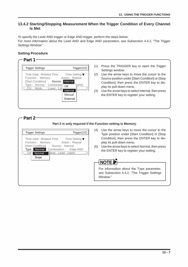
13 – 7
13. USING THE TRIGGER FUNCTIONS
Part 1
Part 2
13.4.2 Starting/Stopping Measurement When the Trigger Condition of Every ChannelIs Met
To specify the Level AND trigger or Edge AND trigger, perform the steps below.For more information about the Level AND and Edge AND parameters, see Subsection 4.4.2, “The TriggerSettings Window.”
Setting Procedure
(4) Use the arrow keys to move the cursor to theType position under [Start Condition] or [StopCondition], then press the ENTER key to dis-play its pull-down menu.
(5) Use the arrow keys to select Normal, then pressthe ENTER key to register your setting.
NOTEFor information about the Type parameter,see Subsection 4.4.2, “The Trigger SettingsWindow.”
Part 2 is only required if the Function setting is Memory.
(1) Press the TRIGGER key to open the TriggerSettings window.
(2) Use the arrow keys to move the cursor to theSource position under [Start Condition] or [StopCondition], then press the ENTER key to dis-play its pull-down menu.
(3) Use the arrow keys to select Internal, then pressthe ENTER key to register your setting.
Trigger Settings Trigger(1/2)
Time Gate : Relative Time Time SettingFunction : Memory Action : Repeat[Start Condition] Source : InternalType : Normal Combination : Edge AND
CH: Mode Lower - Level - UpperOffInternalManualExternal
Trigger Settings Trigger(1/2)
Time Gate : Relative Time Time SettingFunction : Memory Action : Repeat[Start Condition] Source : InternalType : Normal Combination : Edge AND
CH: Mode Lower - Level - UpperNormalSlope
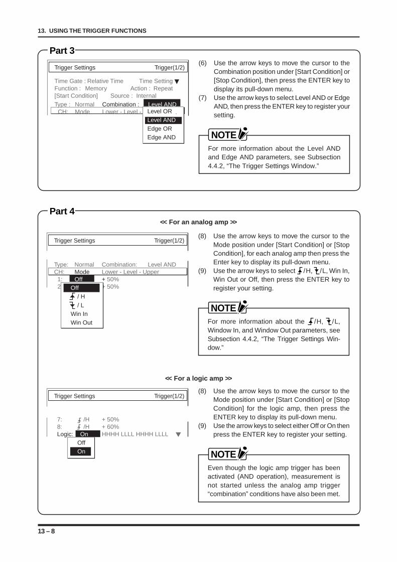
13 – 8
13. USING THE TRIGGER FUNCTIONS
Part 3
Trigger Settings Trigger(1/2)
Time Gate : Relative Time Time SettingFunction : Memory Action : Repeat[Start Condition] Source : InternalType : Normal Combination : Level AND
CH: Mode Lower - Level - UpperLevel ORLevel ANDEdge OREdge AND
(6) Use the arrow keys to move the cursor to theCombination position under [Start Condition] or[Stop Condition], then press the ENTER key todisplay its pull-down menu.
(7) Use the arrow keys to select Level AND or EdgeAND, then press the ENTER key to register yoursetting.
NOTEFor more information about the Level ANDand Edge AND parameters, see Subsection4.4.2, “The Trigger Settings Window.”
Part 4
Trigger Settings Trigger(1/2)
Type: Normal Combination: Level ANDCH: Mode Lower - Level - Upper 1: Off + 50% 2: Off + 50%Off
/ H / LWin InWin Out
(8) Use the arrow keys to move the cursor to theMode position under [Start Condition] or [StopCondition], for each analog amp then press theEnter key to display its pull-down menu.
(9) Use the arrow keys to select /H, /L, Win In,Win Out or Off, then press the ENTER key toregister your setting.
NOTEFor more information about the /H, /L,Window In, and Window Out parameters, seeSubsection 4.4.2, “The Trigger Settings Win-dow.”
(8) Use the arrow keys to move the cursor to theMode position under [Start Condition] or [StopCondition] for the logic amp, then press theENTER key to display its pull-down menu.
(9) Use the arrow keys to select either Off or On thenpress the ENTER key to register your setting.
NOTEEven though the logic amp trigger has beenactivated (AND operation), measurement isnot started unless the analog amp trigger“combination” conditions have also been met.
<< For an analog amp >>
Trigger Settings Trigger(1/2)
7: /H + 50%8: /H + 60%Logic: On HHHH LLLL HHHH LLLL
OffOn
<< For a logic amp >>
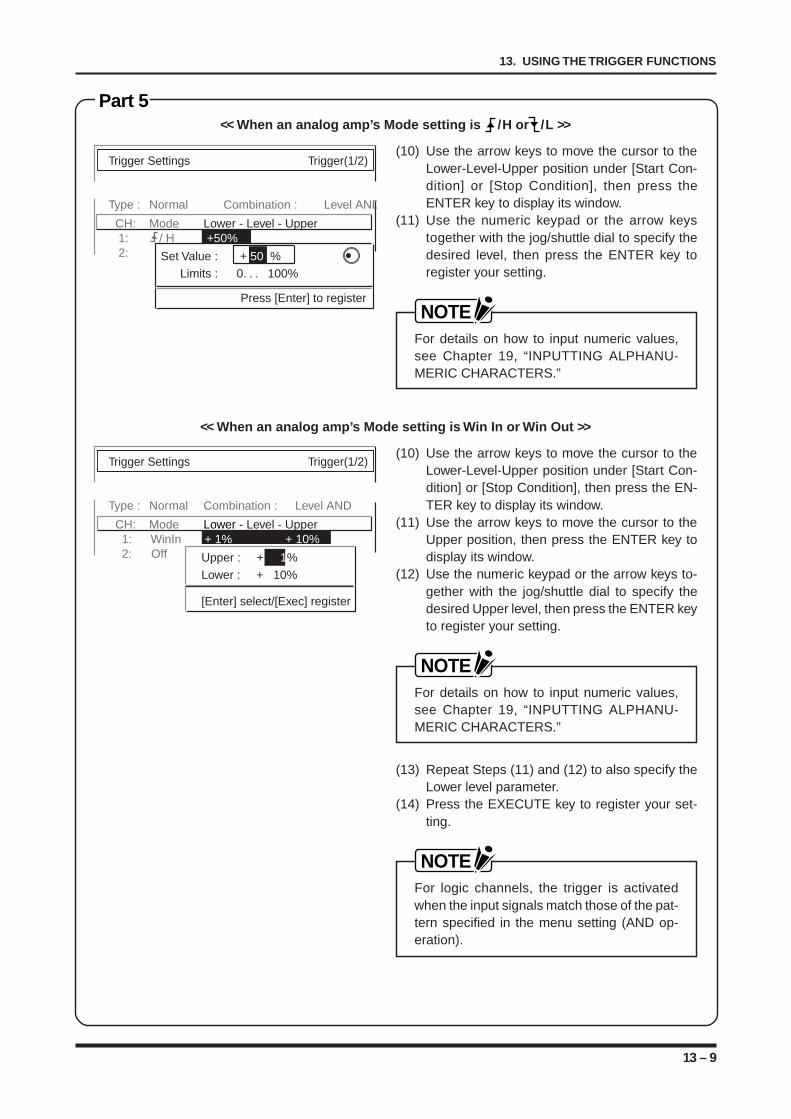
13 – 9
13. USING THE TRIGGER FUNCTIONS
Part 5
Trigger Settings Trigger(1/2)
Type : Normal Combination : Level AND
CH: Mode Lower - Level - Upper 1: / H +50% 2: OffSet Value : + 50 %
Limits : 0. . . 100%
Press [Enter] to register
Trigger Settings Trigger(1/2)
Type : Normal Combination : Level AND
CH: Mode Lower - Level - Upper 1: WinIn + 1% + 10% 2: Off Upper : + 1%
Lower : + 10%
[Enter] select/[Exec] register
(10) Use the arrow keys to move the cursor to theLower-Level-Upper position under [Start Con-dition] or [Stop Condition], then press theENTER key to display its window.
(11) Use the numeric keypad or the arrow keystogether with the jog/shuttle dial to specify thedesired level, then press the ENTER key toregister your setting.
NOTEFor details on how to input numeric values,see Chapter 19, “INPUTTING ALPHANU-MERIC CHARACTERS.”
<< When an analog amp’s Mode setting is /H or /L >>
(10) Use the arrow keys to move the cursor to theLower-Level-Upper position under [Start Con-dition] or [Stop Condition], then press the EN-TER key to display its window.
(11) Use the arrow keys to move the cursor to theUpper position, then press the ENTER key todisplay its window.
(12) Use the numeric keypad or the arrow keys to-gether with the jog/shuttle dial to specify thedesired Upper level, then press the ENTER keyto register your setting.
NOTEFor details on how to input numeric values,see Chapter 19, “INPUTTING ALPHANU-MERIC CHARACTERS.”
(13) Repeat Steps (11) and (12) to also specify theLower level parameter.
(14) Press the EXECUTE key to register your set-ting.
NOTEFor logic channels, the trigger is activatedwhen the input signals match those of the pat-tern specified in the menu setting (AND op-eration).
<< When an analog amp’s Mode setting is Win In or Win Out >>
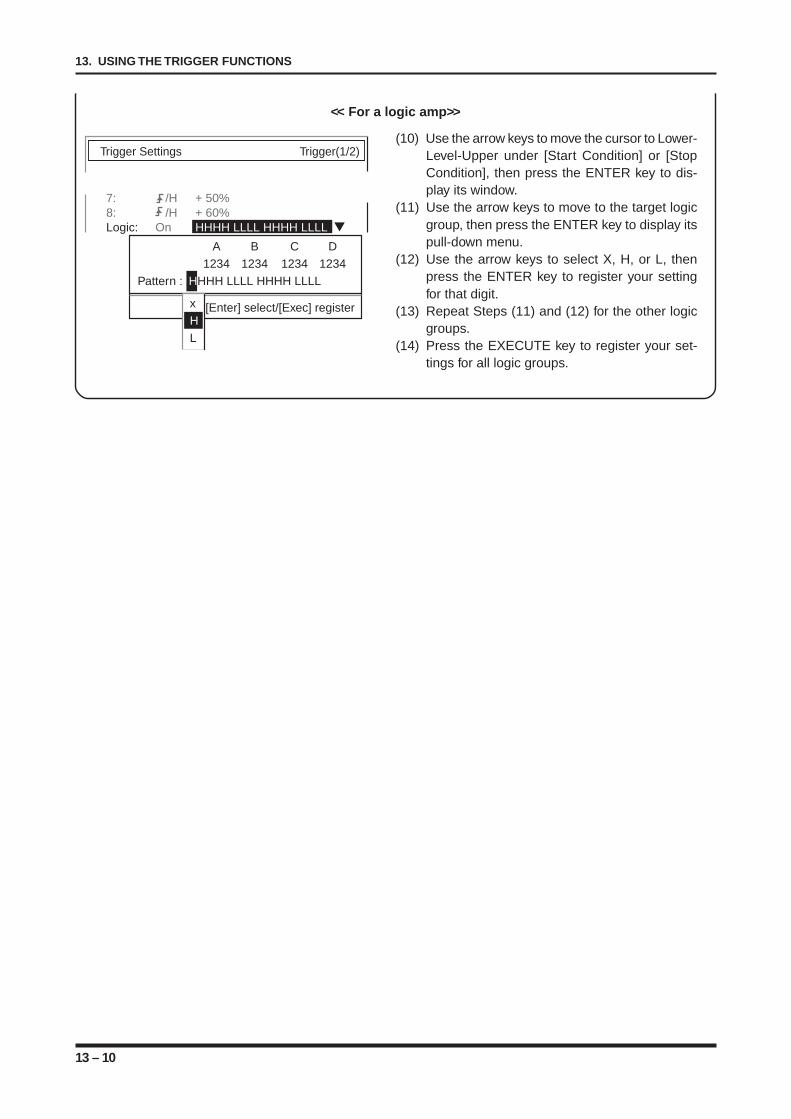
13 – 10
13. USING THE TRIGGER FUNCTIONS
(10) Use the arrow keys to move the cursor to Lower-Level-Upper under [Start Condition] or [StopCondition], then press the ENTER key to dis-play its window.
(11) Use the arrow keys to move to the target logicgroup, then press the ENTER key to display itspull-down menu.
(12) Use the arrow keys to select X, H, or L, thenpress the ENTER key to register your settingfor that digit.
(13) Repeat Steps (11) and (12) for the other logicgroups.
(14) Press the EXECUTE key to register your set-tings for all logic groups.
<< For a logic amp>>
Trigger Settings Trigger(1/2)
7: /H + 50%8: /H + 60%Logic: On HHHH LLLL HHHH LLLL
A B C D1234 1234 1234 1234
Pattern : HHHH LLLL HHHH LLLL
[Enter] select/[Exec] registerxHL
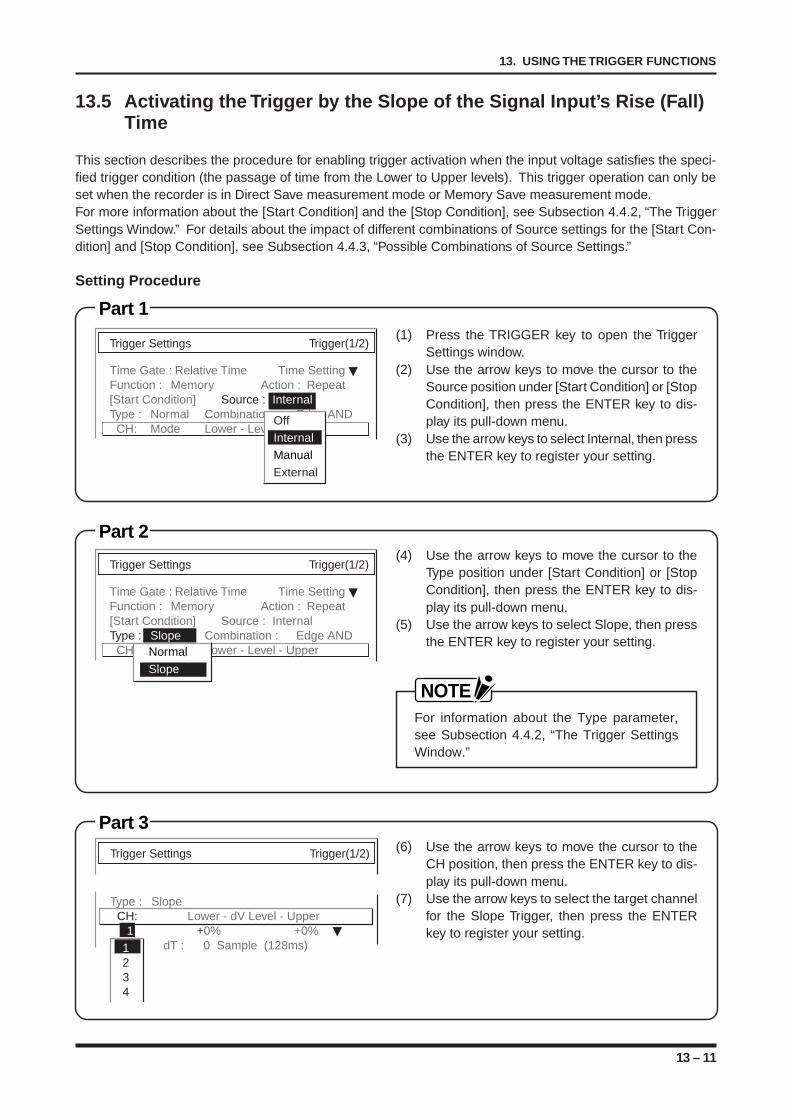
13 – 11
13. USING THE TRIGGER FUNCTIONS
13.5 Activating the Trigger by the Slope of the Signal Input’s Rise (Fall)Time
This section describes the procedure for enabling trigger activation when the input voltage satisfies the speci-fied trigger condition (the passage of time from the Lower to Upper levels). This trigger operation can only beset when the recorder is in Direct Save measurement mode or Memory Save measurement mode.For more information about the [Start Condition] and the [Stop Condition], see Subsection 4.4.2, “The TriggerSettings Window.” For details about the impact of different combinations of Source settings for the [Start Con-dition] and [Stop Condition], see Subsection 4.4.3, “Possible Combinations of Source Settings.”
Setting Procedure
Part 1(1) Press the TRIGGER key to open the Trigger
Settings window.(2) Use the arrow keys to move the cursor to the
Source position under [Start Condition] or [StopCondition], then press the ENTER key to dis-play its pull-down menu.
(3) Use the arrow keys to select Internal, then pressthe ENTER key to register your setting.
Trigger Settings Trigger(1/2)
Time Gate : Relative Time Time SettingFunction : Memory Action : Repeat[Start Condition] Source : InternalType : Normal Combination : Edge AND
CH: Mode Lower - Level - UpperOffInternalManualExternal
Part 2(4) Use the arrow keys to move the cursor to the
Type position under [Start Condition] or [StopCondition], then press the ENTER key to dis-play its pull-down menu.
(5) Use the arrow keys to select Slope, then pressthe ENTER key to register your setting.
NOTEFor information about the Type parameter,see Subsection 4.4.2, “The Trigger SettingsWindow.”
Trigger Settings Trigger(1/2)
Time Gate : Relative Time Time SettingFunction : Memory Action : Repeat[Start Condition] Source : InternalType : Slope Combination : Edge AND
CH: Mode Lower - Level - UpperNormalSlope
Part 3(6) Use the arrow keys to move the cursor to the
CH position, then press the ENTER key to dis-play its pull-down menu.
(7) Use the arrow keys to select the target channelfor the Slope Trigger, then press the ENTERkey to register your setting.
Trigger Settings Trigger(1/2)
Type : SlopeCH: Lower - dV Level - Upper
1 +0% +0% dT : 0 Sample (128ms)1
234
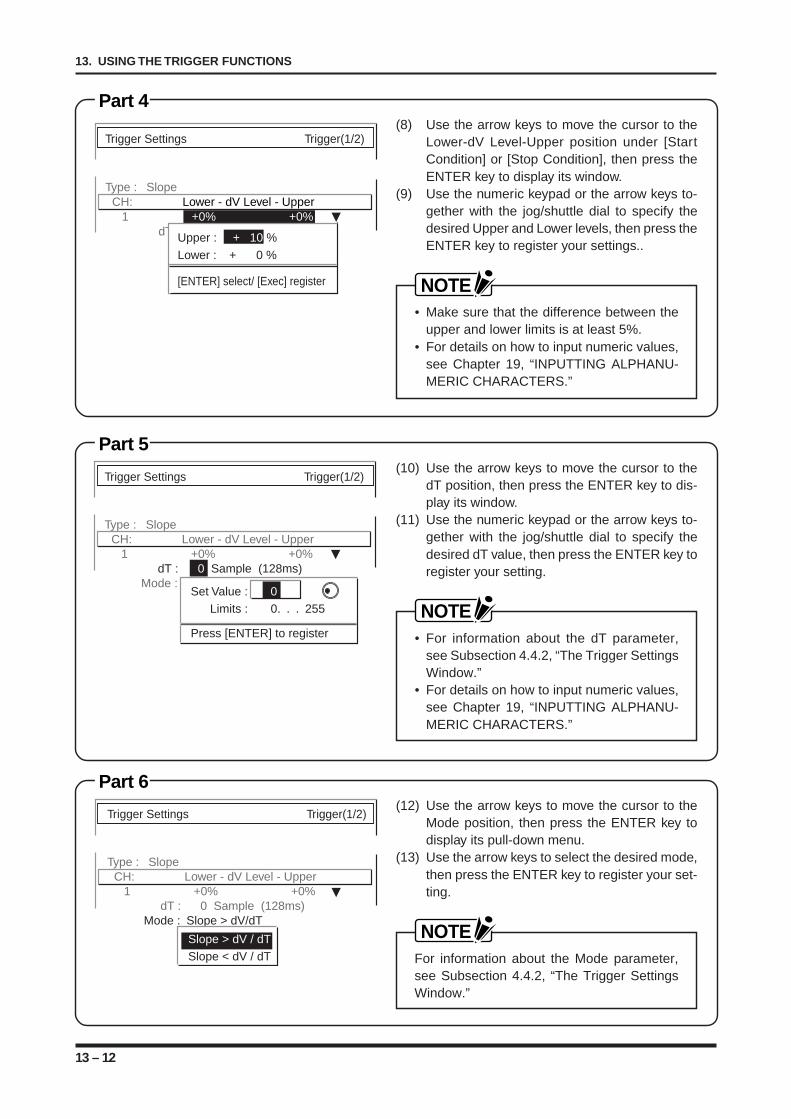
13 – 12
13. USING THE TRIGGER FUNCTIONS
Part 6(12) Use the arrow keys to move the cursor to the
Mode position, then press the ENTER key todisplay its pull-down menu.
(13) Use the arrow keys to select the desired mode,then press the ENTER key to register your set-ting.
NOTEFor information about the Mode parameter,see Subsection 4.4.2, “The Trigger SettingsWindow.”
Trigger Settings Trigger(1/2)
Type : SlopeCH: Lower - dV Level - Upper
1 +0% +0% dT : 0 Sample (128ms) Mode : Slope > dV/dT
Slope > dV / dTSlope < dV / dT
Part 5(10) Use the arrow keys to move the cursor to the
dT position, then press the ENTER key to dis-play its window.
(11) Use the numeric keypad or the arrow keys to-gether with the jog/shuttle dial to specify thedesired dT value, then press the ENTER key toregister your setting.
NOTE• For information about the dT parameter,
see Subsection 4.4.2, “The Trigger SettingsWindow.”
• For details on how to input numeric values,see Chapter 19, “INPUTTING ALPHANU-MERIC CHARACTERS.”
Trigger Settings Trigger(1/2)
Type : SlopeCH: Lower - dV Level - Upper
1 +0% +0% dT : 0 Sample (128ms) Mode : Input > dV/dT
Set Value : 0Limits : 0. . . 255
Press [ENTER] to register
Part 4(8) Use the arrow keys to move the cursor to the
Lower-dV Level-Upper position under [StartCondition] or [Stop Condition], then press theENTER key to display its window.
(9) Use the numeric keypad or the arrow keys to-gether with the jog/shuttle dial to specify thedesired Upper and Lower levels, then press theENTER key to register your settings..
NOTE• Make sure that the difference between the
upper and lower limits is at least 5%.• For details on how to input numeric values,
see Chapter 19, “INPUTTING ALPHANU-MERIC CHARACTERS.”
Trigger Settings Trigger(1/2)
Type : SlopeCH: Lower - dV Level - Upper
1 +0% +0% dT : 0 Sample (128ms)Upper : + 10 %
Lower : + 0 %
[ENTER] select/ [Exec] register
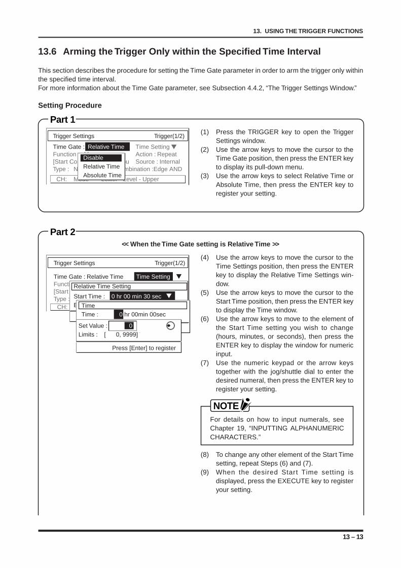
13 – 13
13. USING THE TRIGGER FUNCTIONS
13.6 Arming the Trigger Only within the Specified Time Interval
This section describes the procedure for setting the Time Gate parameter in order to arm the trigger only withinthe specified time interval.For more information about the Time Gate parameter, see Subsection 4.4.2, “The Trigger Settings Window.”
Setting Procedure
Part 1(1) Press the TRIGGER key to open the Trigger
Settings window.(2) Use the arrow keys to move the cursor to the
Time Gate position, then press the ENTER keyto display its pull-down menu.
(3) Use the arrow keys to select Relative Time orAbsolute Time, then press the ENTER key toregister your setting.
Trigger Settings Trigger(1/2)
Time Gate : Relative Time Time SettingFunction : Memory Action : Repeat[Start Condi Sou Source : InternalType : Normal Combination :Edge AND
CH: Mode Lower - Level - Upper
DisableRelative TimeAbsolute Time
Part 2
(4) Use the arrow keys to move the cursor to theTime Settings position, then press the ENTERkey to display the Relative Time Settings win-dow.
(5) Use the arrow keys to move the cursor to theStart Time position, then press the ENTER keyto display the Time window.
(6) Use the arrow keys to move to the element ofthe Start Time setting you wish to change(hours, minutes, or seconds), then press theENTER key to display the window for numericinput.
(7) Use the numeric keypad or the arrow keystogether with the jog/shuttle dial to enter thedesired numeral, then press the ENTER key toregister your setting.
NOTEFor details on how to input numerals, seeChapter 19, “INPUTTING ALPHANUMERICCHARACTERS.”
(8) To change any other element of the Start Timesetting, repeat Steps (6) and (7).
(9) When the desired Start Time setting isdisplayed, press the EXECUTE key to registeryour setting.
<< When the Time Gate setting is Relative Time >>
Trigger Settings Trigger(1/2)
Time Gate : Relative Time Time SettingFunction[Start Condition]Type :
CH:
Relative Time Setting
Start Time : 0 hr 00 min 30 secEndTime
Time : 0 hr 00min 00sec
Set Value : 0Limits : [ 0, 9999]
Press [Enter] to register
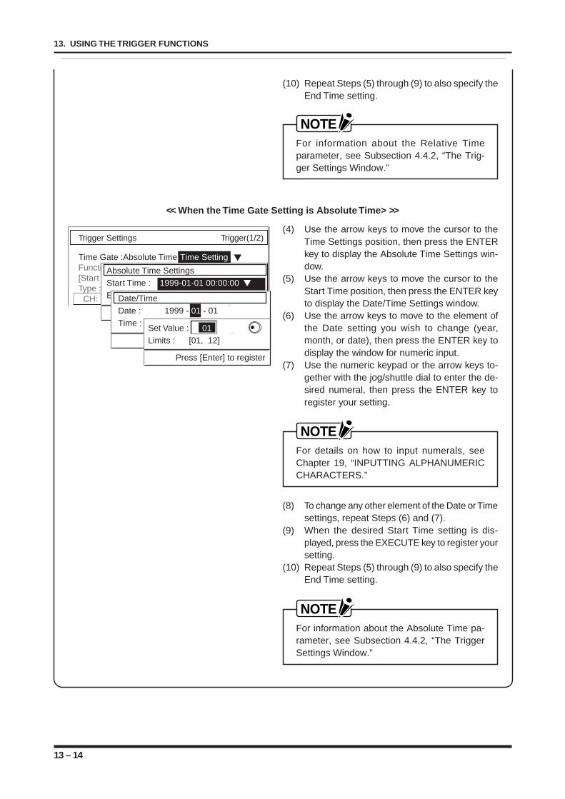
13 – 14
13. USING THE TRIGGER FUNCTIONS
(4) Use the arrow keys to move the cursor to theTime Settings position, then press the ENTERkey to display the Absolute Time Settings win-dow.
(5) Use the arrow keys to move the cursor to theStart Time position, then press the ENTER keyto display the Date/Time Settings window.
(6) Use the arrow keys to move to the element ofthe Date setting you wish to change (year,month, or date), then press the ENTER key todisplay the window for numeric input.
(7) Use the numeric keypad or the arrow keys to-gether with the jog/shuttle dial to enter the de-sired numeral, then press the ENTER key toregister your setting.
NOTEFor details on how to input numerals, seeChapter 19, “INPUTTING ALPHANUMERICCHARACTERS.”
(8) To change any other element of the Date or Timesettings, repeat Steps (6) and (7).
(9) When the desired Start Time setting is dis-played, press the EXECUTE key to register yoursetting.
(10) Repeat Steps (5) through (9) to also specify theEnd Time setting.
NOTEFor information about the Absolute Time pa-rameter, see Subsection 4.4.2, “The TriggerSettings Window.”
<< When the Time Gate Setting is Absolute Time> >>
Trigger Settings Trigger(1/2)
Time Gate :Absolute Time Time SettingFunction[Start Type :
CH:
Absolute Time SettingsStart Time : 1999-01-01 00:00:00EndDate/Time
Date : 1999 - 01 - 01Time : 00:00:00
Set Value : 01Limits : [01, 12]
Press [Enter] to register
(10) Repeat Steps (5) through (9) to also specify theEnd Time setting.
NOTEFor information about the Relative Timeparameter, see Subsection 4.4.2, “The Trig-ger Settings Window.”
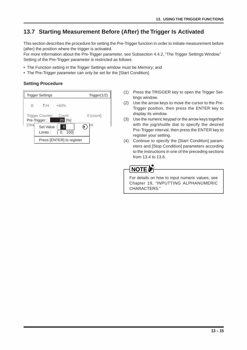
13 – 15
13. USING THE TRIGGER FUNCTIONS
13.7 Starting Measurement Before (After) the Trigger Is Activated
This section describes the procedure for setting the Pre-Trigger function in order to initiate measurement before(after) the position where the trigger is activated.For more information about the Pre-Trigger parameter, see Subsection 4.4.2, “The Trigger Settings Window.”Setting of the Pre-Trigger parameter is restricted as follows:
• The Function setting in the Trigger Settings window must be Memory; and• The Pre-Trigger parameter can only be set for the [Start Condition].
Setting Procedure
(1) Press the TRIGGER key to open the Trigger Set-tings window.
(2) Use the arrow keys to move the cursor to the Pre-Trigger position, then press the ENTER key todisplay its window.
(3) Use the numeric keypad or the arrow keys togetherwith the jog/shuttle dial to specify the desiredPre-Trigger interval, then press the ENTER key toregister your setting.
(4) Continue to specify the [Start Condition] param-eters and [Stop Condition] parameters accordingto the instructions in one of the preceding sectionsfrom 13.4 to 13.6.
NOTEFor details on how to input numeric values, seeChapter 19, “INPUTTING ALPHANUMERICCHARACTERS.”
Trigger Settings Trigger(1/2)
8: /H +60%
Trigger Counter : Count 0 [count]Pre-Trigger : 20 [%][Stop Condition] Source : InternalSet Value : 0
Limits : [ 0, 100]
Press [ENTER] to register
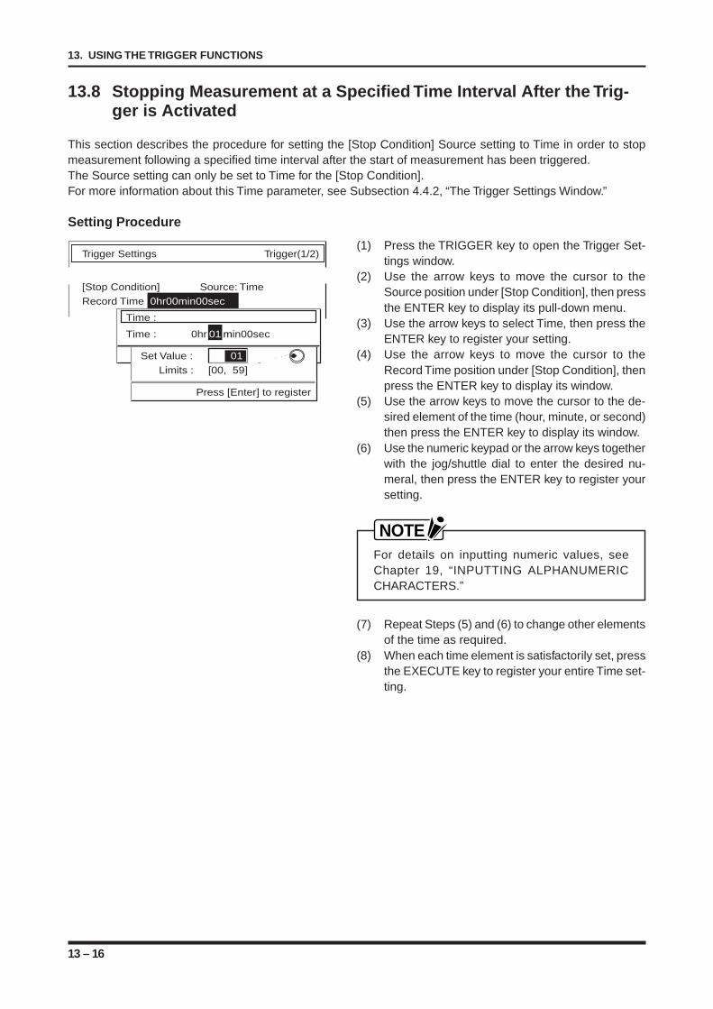
13 – 16
13. USING THE TRIGGER FUNCTIONS
13.8 Stopping Measurement at a Specified Time Interval After the Trig-ger is Activated
This section describes the procedure for setting the [Stop Condition] Source setting to Time in order to stopmeasurement following a specified time interval after the start of measurement has been triggered.The Source setting can only be set to Time for the [Stop Condition].For more information about this Time parameter, see Subsection 4.4.2, “The Trigger Settings Window.”
Setting Procedure
(1) Press the TRIGGER key to open the Trigger Set-tings window.
(2) Use the arrow keys to move the cursor to theSource position under [Stop Condition], then pressthe ENTER key to display its pull-down menu.
(3) Use the arrow keys to select Time, then press theENTER key to register your setting.
(4) Use the arrow keys to move the cursor to theRecord Time position under [Stop Condition], thenpress the ENTER key to display its window.
(5) Use the arrow keys to move the cursor to the de-sired element of the time (hour, minute, or second)then press the ENTER key to display its window.
(6) Use the numeric keypad or the arrow keys togetherwith the jog/shuttle dial to enter the desired nu-meral, then press the ENTER key to register yoursetting.
NOTEFor details on inputting numeric values, seeChapter 19, “INPUTTING ALPHANUMERICCHARACTERS.”
(7) Repeat Steps (5) and (6) to change other elementsof the time as required.
(8) When each time element is satisfactorily set, pressthe EXECUTE key to register your entire Time set-ting.
Trigger Settings Trigger(1/2)
[Stop Condition] Source: TimeRecord Time :0hr00min00sec
Time :
Time : 0hr 01 min00sec
[Enter] select/[Exec] registerSet Value : 01 Limits : [00, 59]
Press [Enter] to register
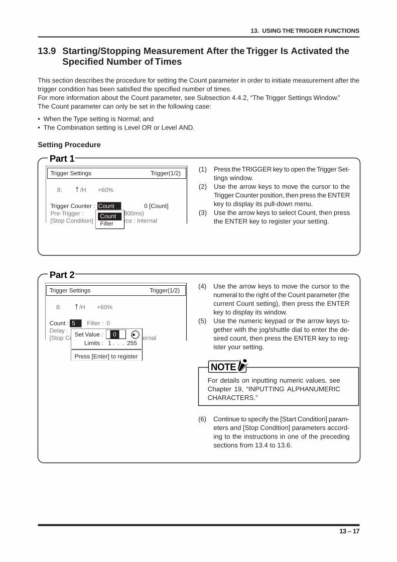
13 – 17
13. USING THE TRIGGER FUNCTIONS
13.9 Starting/Stopping Measurement After the Trigger Is Activated theSpecified Number of Times
This section describes the procedure for setting the Count parameter in order to initiate measurement after thetrigger condition has been satisfied the specified number of times.For more information about the Count parameter, see Subsection 4.4.2, “The Trigger Settings Window.”The Count parameter can only be set in the following case:
• When the Type setting is Normal; and• The Combination setting is Level OR or Level AND.
Setting Procedure
Part 2
Trigger Settings Trigger(1/2)
8: /H +60%
Trigger Counter : Count 0 [Count] Pre-Trigger : 20 % (800ms)[Stop Condition] Source : Internal
CountFilter
Part 1(1) Press the TRIGGER key to open the Trigger Set-
tings window.(2) Use the arrow keys to move the cursor to the
Trigger Counter position, then press the ENTERkey to display its pull-down menu.
(3) Use the arrow keys to select Count, then pressthe ENTER key to register your setting.
(4) Use the arrow keys to move the cursor to thenumeral to the right of the Count parameter (thecurrent Count setting), then press the ENTERkey to display its window.
(5) Use the numeric keypad or the arrow keys to-gether with the jog/shuttle dial to enter the de-sired count, then press the ENTER key to reg-ister your setting.
NOTEFor details on inputting numeric values, seeChapter 19, “INPUTTING ALPHANUMERICCHARACTERS.”
(6) Continue to specify the [Start Condition] param-eters and [Stop Condition] parameters accord-ing to the instructions in one of the precedingsections from 13.4 to 13.6.
Trigger Settings Trigger(1/2)
8: /H +60%
Count : 5 Filter : 0Delay : 20 % (800ms)[Stop Condition] Source : Internal
Set Value : 0Limits : 1 . . . 255
Press [Enter] to register
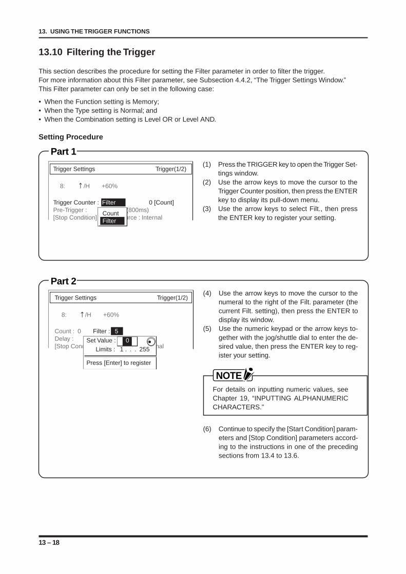
13 – 18
13. USING THE TRIGGER FUNCTIONS
Trigger Settings Trigger(1/2)
8: /H +60%
Trigger Counter : Filter 0 [Count] Pre-Trigger : 20 % (800ms)[Stop Condition] Source : Internal
CountFilter
13.10 Filtering the Trigger
This section describes the procedure for setting the Filter parameter in order to filter the trigger.For more information about this Filter parameter, see Subsection 4.4.2, “The Trigger Settings Window.”This Filter parameter can only be set in the following case:
• When the Function setting is Memory;• When the Type setting is Normal; and• When the Combination setting is Level OR or Level AND.
Setting Procedure
(1) Press the TRIGGER key to open the Trigger Set-tings window.
(2) Use the arrow keys to move the cursor to theTrigger Counter position, then press the ENTERkey to display its pull-down menu.
(3) Use the arrow keys to select Filt., then pressthe ENTER key to register your setting.
Part 2
Part 1
(4) Use the arrow keys to move the cursor to thenumeral to the right of the Filt. parameter (thecurrent Filt. setting), then press the ENTER todisplay its window.
(5) Use the numeric keypad or the arrow keys to-gether with the jog/shuttle dial to enter the de-sired value, then press the ENTER key to reg-ister your setting.
NOTEFor details on inputting numeric values, seeChapter 19, “INPUTTING ALPHANUMERICCHARACTERS.”
(6) Continue to specify the [Start Condition] param-eters and [Stop Condition] parameters accord-ing to the instructions in one of the precedingsections from 13.4 to 13.6.
Trigger Settings Trigger(1/2)
8: /H +60%
Count : 0 Filter : 5Delay : 20 % (800ms)[Stop Condition] Source : Internal
Set Value : 0Limits : 1 . . . 255
Press [Enter] to register
14 – 1
14. USING THE RECORDING FUNCTIONS
CHAPTER 14CHAPTER 14USING THE RECORDING FUNCTIONS
This chapter describes the overall flow of setting param-eters related to recording.
14.1 Various Settings Related to Display and Recording inRECORDER Mode (Display Mode Setting: Y-T)
14.1.1 Changing the Waveform Display Mode of Signal Input to Y-T14.1.2 Changing the Output Destination of Signal Input14.1.3 Outputting Captured Data onto Chart Paper14.1.4 Selecting a Predetermined Chart Speed Setting14.1.5 Specifying a User-Defined Chart Speed Setting14.1.6 Printing Channel ID Nos. on Waveforms14.1.7 Printing Timing Markers or Event Markers14.1.8 Printing a Scale on Chart Paper14.1.9 Printing a List of Current Settings14.1.10 Changing the Record Format and Zone Settings14.1.11 Changing the Grid Setting14.1.12 Enabling the Envelope Function14.1.13 Prioritizing Display of a Specific Channel14.1.14 Changing the Color of Waveform Display14.1.15 Changing the Line Width of Waveforms14.1.16 Printing a Reference Line in Each Zone14.1.17 Changing the Print Interval between Annotations14.1.18 Selecting the No. of Characters in Annotation14.1.19 Selecting the Method for the Control of Annotation Printing14.1.20 Printing a Title at the Top of the Chart Paper14.1.21 Printing a Message or Measured Values for Each Channel14.2 Various Settings Related to Display and Recording in
RECORDER Mode (Display Mode Setting: X-Y)14.2.1 Changing the Waveform Display Mode of Signal Input to X-Y14.2.2 Changing the Output Destination of Signal Input14.2.3 Printing a List of Current Settings14.2.4 Changing the Grid Setting14.2.5 Selecting the Compensation Mode14.2.6 Selecting the Plot On/Off Status for Each XY Number14.2.7 Changing the Color of Waveform Display14.2.8 Selecting the X-Axis and Y-Axis Channels14.3 Recording and Display in LOGGING Mode14.3.1 Changing the Logging Interval14.3.2 Printing a List of the Current Settings14.3.3 Changing the Number of Displayed Zones14.3.4 Assigning a Channel to a Display Zone14.3.5 Changing the Text Color of Each Zone
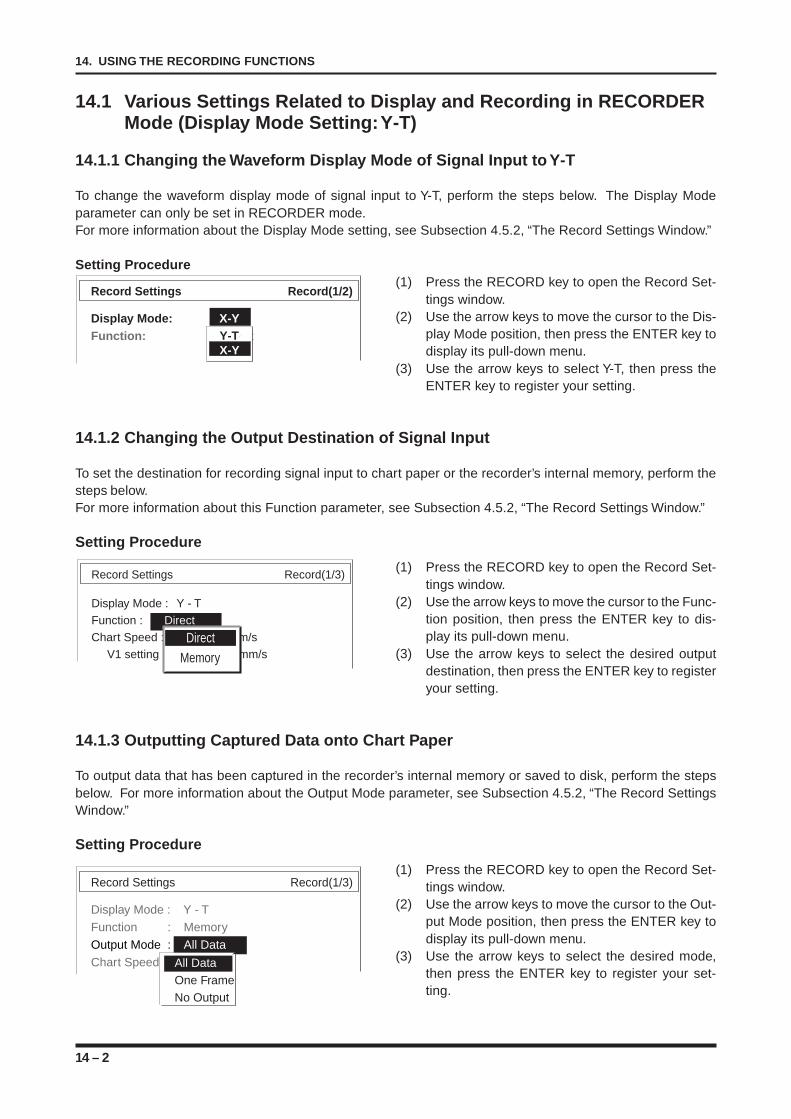
14 – 2
14. USING THE RECORDING FUNCTIONS
14.1 Various Settings Related to Display and Recording in RECORDERMode (Display Mode Setting: Y-T)
14.1.1 Changing the Waveform Display Mode of Signal Input to Y-T
To change the waveform display mode of signal input to Y-T, perform the steps below. The Display Modeparameter can only be set in RECORDER mode.For more information about the Display Mode setting, see Subsection 4.5.2, “The Record Settings Window.”
Setting Procedure(1) Press the RECORD key to open the Record Set-
tings window.(2) Use the arrow keys to move the cursor to the Dis-
play Mode position, then press the ENTER key todisplay its pull-down menu.
(3) Use the arrow keys to select Y-T, then press theENTER key to register your setting.
14.1.2 Changing the Output Destination of Signal Input
To set the destination for recording signal input to chart paper or the recorder’s internal memory, perform thesteps below.For more information about this Function parameter, see Subsection 4.5.2, “The Record Settings Window.”
Setting Procedure
(1) Press the RECORD key to open the Record Set-tings window.
(2) Use the arrow keys to move the cursor to the Func-tion position, then press the ENTER key to dis-play its pull-down menu.
(3) Use the arrow keys to select the desired outputdestination, then press the ENTER key to registeryour setting.
14.1.3 Outputting Captured Data onto Chart Paper
To output data that has been captured in the recorder’s internal memory or saved to disk, perform the stepsbelow. For more information about the Output Mode parameter, see Subsection 4.5.2, “The Record SettingsWindow.”
Setting Procedure
(1) Press the RECORD key to open the Record Set-tings window.
(2) Use the arrow keys to move the cursor to the Out-put Mode position, then press the ENTER key todisplay its pull-down menu.
(3) Use the arrow keys to select the desired mode,then press the ENTER key to register your set-ting.
Record Settings Record(1/3)
Display Mode : Y - T
Function : Direct
Chart Speed : 20mm/s
V1 setting : 10 mm/s Direct
Memory
Record Settings Record(1/3)
Display Mode : Y - T
Function : Memory
Output Mode : All Data
Chart Speed : 20mm/sAll DataOne FrameNo Output
Record Settings Record(1/2)
Display Mode: X-YFunction: DirectY-T
X-Y
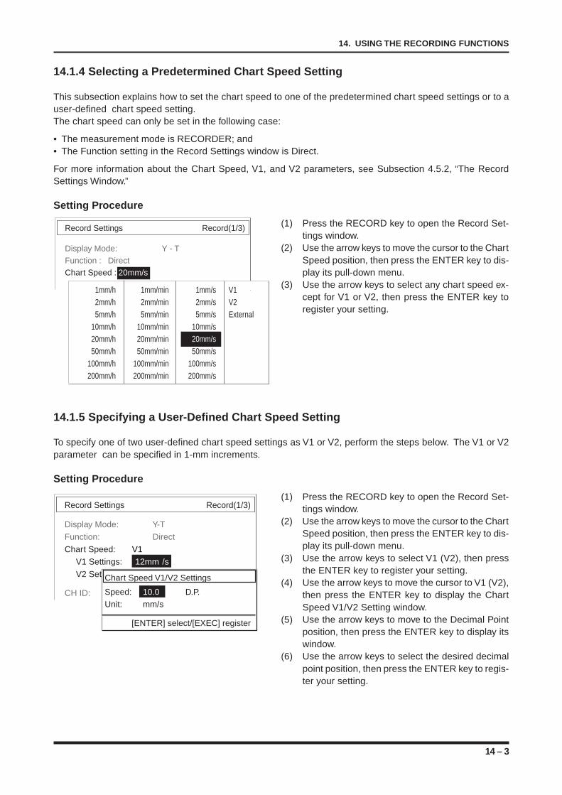
14 – 3
14. USING THE RECORDING FUNCTIONS
14.1.4 Selecting a Predetermined Chart Speed Setting
This subsection explains how to set the chart speed to one of the predetermined chart speed settings or to auser-defined chart speed setting.The chart speed can only be set in the following case:
• The measurement mode is RECORDER; and• The Function setting in the Record Settings window is Direct.
For more information about the Chart Speed, V1, and V2 parameters, see Subsection 4.5.2, “The RecordSettings Window.”
Setting Procedure
(1) Press the RECORD key to open the Record Set-tings window.
(2) Use the arrow keys to move the cursor to the ChartSpeed position, then press the ENTER key to dis-play its pull-down menu.
(3) Use the arrow keys to select any chart speed ex-cept for V1 or V2, then press the ENTER key toregister your setting.
14.1.5 Specifying a User-Defined Chart Speed Setting
To specify one of two user-defined chart speed settings as V1 or V2, perform the steps below. The V1 or V2parameter can be specified in 1-mm increments.
Setting Procedure
(1) Press the RECORD key to open the Record Set-tings window.
(2) Use the arrow keys to move the cursor to the ChartSpeed position, then press the ENTER key to dis-play its pull-down menu.
(3) Use the arrow keys to select V1 (V2), then pressthe ENTER key to register your setting.
(4) Use the arrow keys to move the cursor to V1 (V2),then press the ENTER key to display the ChartSpeed V1/V2 Setting window.
(5) Use the arrow keys to move to the Decimal Pointposition, then press the ENTER key to display itswindow.
(6) Use the arrow keys to select the desired decimalpoint position, then press the ENTER key to regis-ter your setting.
Record Settings Record(1/3)
Display Mode: Y - T
Function : Direct
Chart Speed : 20mm/s
V1 setting: 10 mm/s1mm/h 1mm/min 1mm/s V12mm/h 2mm/min 2mm/s V25mm/h 5mm/min 5mm/s External
10mm/h 10mm/min 10mm/s20mm/h 20mm/min 20mm/s50mm/h 50mm/min 50mm/s
100mm/h 100mm/min 100mm/s200mm/h 200mm/min 200mm/s
Record Settings Record(1/3)
Display Mode: Y-T
Function: Direct
Chart Speed: V1
V1 Settings: 12mm /s
V2 Setings: 28mm /s
CH ID: On
Chart Speed V1/V2 Settings
Speed: 10.0 D.P.Unit: mm/s
[ENTER] select/[EXEC] register
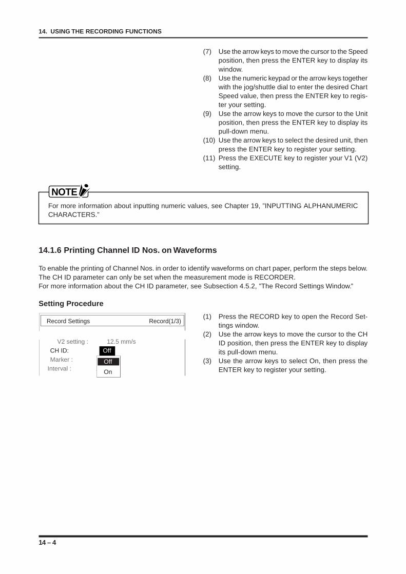
14 – 4
14. USING THE RECORDING FUNCTIONS
Record Settings Record(1/3)
V2 setting : 12.5 mm/s
CH ID: Off
Marker : Timing
Interval : 10sOff
On
(7) Use the arrow keys to move the cursor to the Speedposition, then press the ENTER key to display itswindow.
(8) Use the numeric keypad or the arrow keys togetherwith the jog/shuttle dial to enter the desired ChartSpeed value, then press the ENTER key to regis-ter your setting.
(9) Use the arrow keys to move the cursor to the Unitposition, then press the ENTER key to display itspull-down menu.
(10) Use the arrow keys to select the desired unit, thenpress the ENTER key to register your setting.
(11) Press the EXECUTE key to register your V1 (V2)setting.
NOTEFor more information about inputting numeric values, see Chapter 19, ”INPUTTING ALPHANUMERICCHARACTERS.”
14.1.6 Printing Channel ID Nos. on Waveforms
To enable the printing of Channel Nos. in order to identify waveforms on chart paper, perform the steps below.The CH ID parameter can only be set when the measurement mode is RECORDER.For more information about the CH ID parameter, see Subsection 4.5.2, ”The Record Settings Window.”
Setting Procedure
(1) Press the RECORD key to open the Record Set-tings window.
(2) Use the arrow keys to move the cursor to the CHID position, then press the ENTER key to displayits pull-down menu.
(3) Use the arrow keys to select On, then press theENTER key to register your setting.
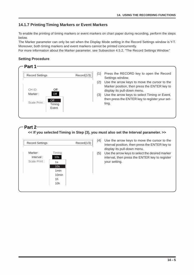
14 – 5
14. USING THE RECORDING FUNCTIONS
Part 1
14.1.7 Printing Timing Markers or Event Markers
To enable the printing of timing markers or event markers on chart paper during recording, perform the stepsbelow.The Marker parameter can only be set when the Display Mode setting in the Record Settings window is Y-T.Moreover, both timing markers and event markers cannot be printed concurrently.For more information about the Marker parameter, see Subsection 4.5.2, ”The Record Settings Window.”
Setting Procedure
(1) Press the RECORD key to open the RecordSettings window.
(2) Use the arrow keys to move the cursor to theMarker position, then press the ENTER key todisplay its pull-down menu.
(3) Use the arrow keys to select Timing or Event,then press the ENTER key to register your set-ting.
<< If you selected Timing in Step (3), you must also set the Interval parameter. >>
(4) Use the arrow keys to move the cursor to theInterval position, then press the ENTER key todisplay its pull-down menu.
(5) Use the arrow keys to select the desired markerinterval, then press the ENTER key to registeryour setting.
Record Settings Record(1/3)
CH ID: Off
Marker : Off
Scale Print :OffTimingEvent
Part 2
Record Settings Record(1/3)
Marker : Timing
Interval : 10s
Scale Print : Off1s10s1min10min1h10h
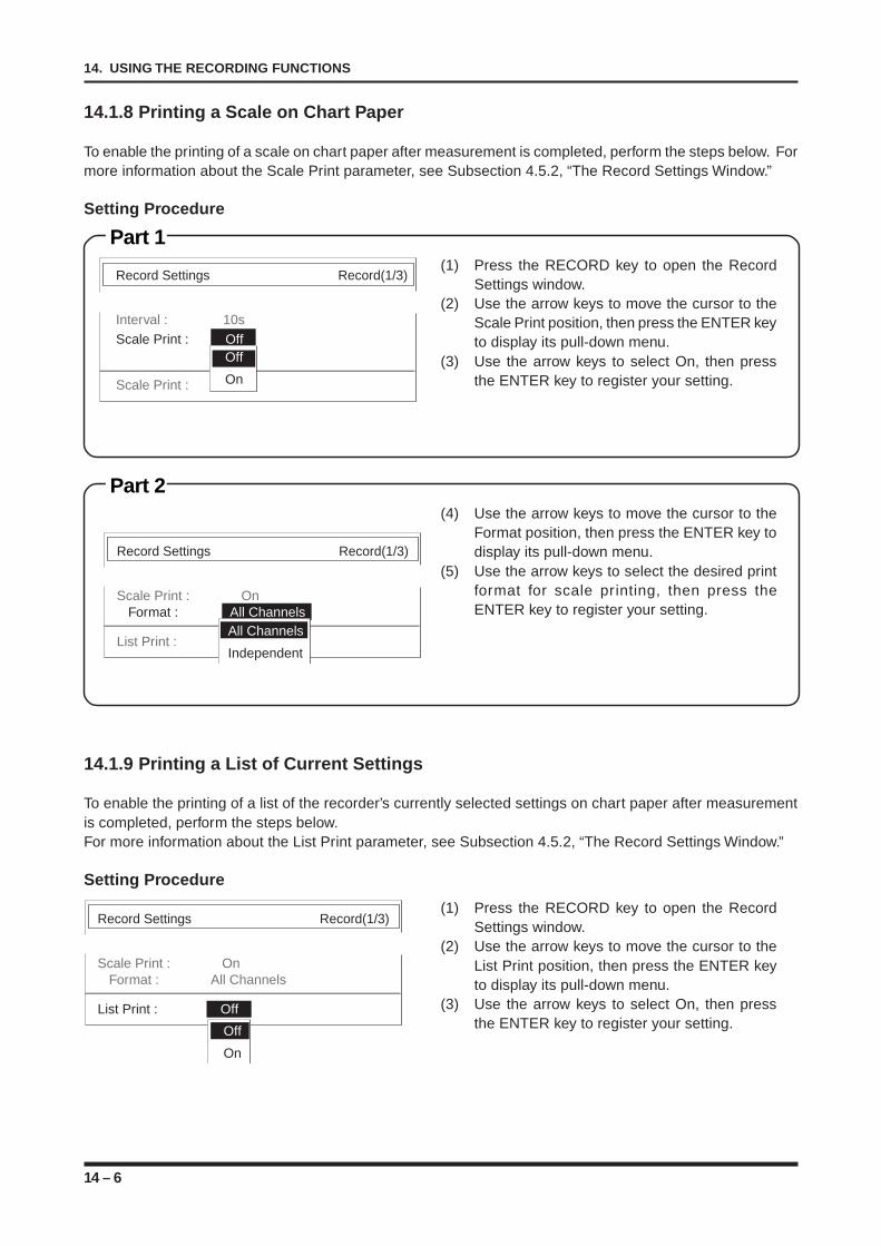
14 – 6
14. USING THE RECORDING FUNCTIONS
Record Settings Record(1/3)
Scale Print : On Format : All Channels
List Print : Off
Off
On
14.1.8 Printing a Scale on Chart Paper
To enable the printing of a scale on chart paper after measurement is completed, perform the steps below. Formore information about the Scale Print parameter, see Subsection 4.5.2, “The Record Settings Window.”
Setting Procedure
Part 1(1) Press the RECORD key to open the Record
Settings window.(2) Use the arrow keys to move the cursor to the
Scale Print position, then press the ENTER keyto display its pull-down menu.
(3) Use the arrow keys to select On, then pressthe ENTER key to register your setting.
Part 2(4) Use the arrow keys to move the cursor to the
Format position, then press the ENTER key todisplay its pull-down menu.
(5) Use the arrow keys to select the desired printformat for scale printing, then press theENTER key to register your setting.
14.1.9 Printing a List of Current Settings
To enable the printing of a list of the recorder’s currently selected settings on chart paper after measurementis completed, perform the steps below.For more information about the List Print parameter, see Subsection 4.5.2, “The Record Settings Window.”
Setting Procedure
(1) Press the RECORD key to open the RecordSettings window.
(2) Use the arrow keys to move the cursor to theList Print position, then press the ENTER keyto display its pull-down menu.
(3) Use the arrow keys to select On, then pressthe ENTER key to register your setting.
Record Settings Record(1/3)
Interval : 10s
Scale Print : Off
Scale Print : Off
Off
On
Record Settings Record(1/3)
Scale Print : On Format : All Channels
List Print :All Channels
Independent
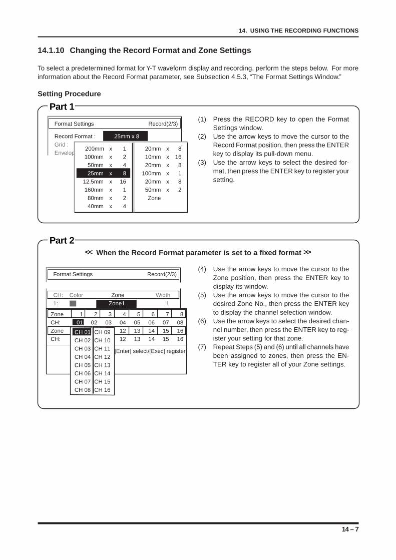
14 – 7
14. USING THE RECORDING FUNCTIONS
14.1.10 Changing the Record Format and Zone Settings
To select a predetermined format for Y-T waveform display and recording, perform the steps below. For moreinformation about the Record Format parameter, see Subsection 4.5.3, “The Format Settings Window.”
Setting Procedure
Part 1(1) Press the RECORD key to open the Format
Settings window.(2) Use the arrow keys to move the cursor to the
Record Format position, then press the ENTERkey to display its pull-down menu.
(3) Use the arrow keys to select the desired for-mat, then press the ENTER key to register yoursetting.
Part 2<< When the Record Format parameter is set to a fixed format >>
(4) Use the arrow keys to move the cursor to theZone position, then press the ENTER key todisplay its window.
(5) Use the arrow keys to move the cursor to thedesired Zone No., then press the ENTER keyto display the channel selection window.
(6) Use the arrow keys to select the desired chan-nel number, then press the ENTER key to reg-ister your setting for that zone.
(7) Repeat Steps (5) and (6) until all channels havebeen assigned to zones, then press the EN-TER key to register all of your Zone settings.
Format Settings Record(2/3)
Record Format : 25mm x 8
Grid : 10mm Fine
Envelope : Off 200mm x 1 20mm x 8
100mm x 2 10mm x 1650mm x 4 20mm x 825mm x 8 100mm x 1
12.5mm x 16 20mm x 8160mm x 1 50mm x 280mm x 2 Zone40mm x 4
Format Settings Record(2/3)
CH: Color Zone Width
1: Zone1 1
2: Zone2 1Zone 1 2 3 4 5 6 7 8
CH: 01 02 03 04 05 06 07 08
Zone 9 10 11 12 13 14 15 16
CH: 09 10 11 12 13 14 15 16
[Enter] select/[Exec] register
CH 01 CH 09
CH 02 CH 10
CH 03 CH 11
CH 04 CH 12
CH 05 CH 13
CH 06 CH 14
CH 07 CH 15
CH 08 CH 16
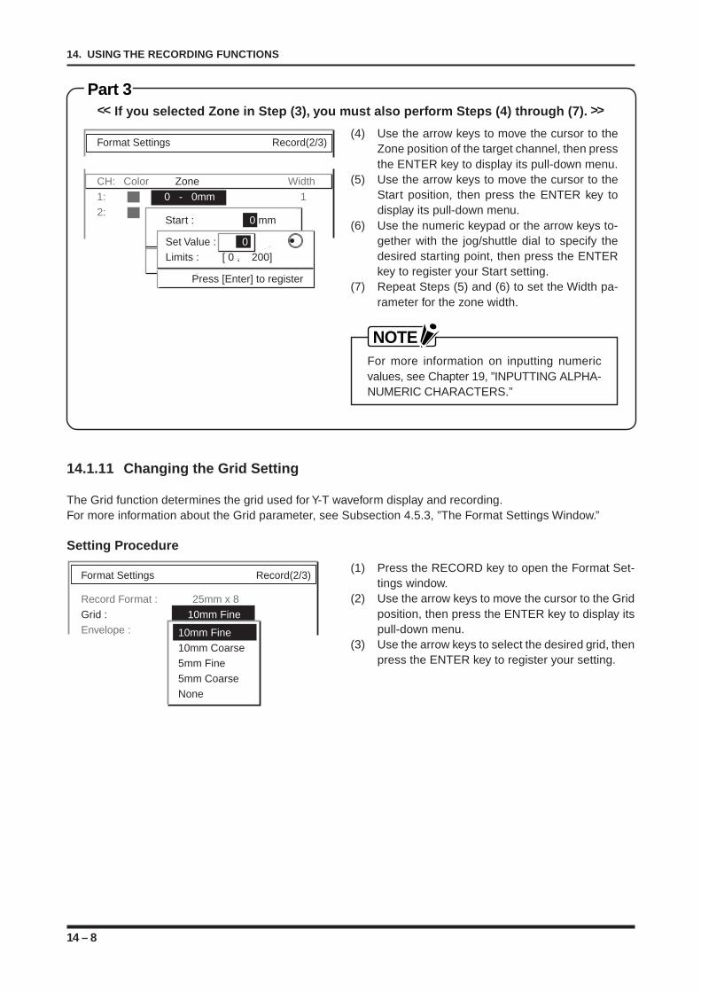
14 – 8
14. USING THE RECORDING FUNCTIONS
Format Settings Record(2/3)
Record Format : 25mm x 8
Grid : 10mm Fine
Envelope : 10mm Fine10mm Coarse5mm Fine5mm CoarseNone
Format Settings Record(2/3)
CH: Color Zone Width
1: 0 - 0mm 1
2: 0 - 0mm + 0.0% 1Start : 0 mm
Width : 0 mm
[Enter] select/[Exec] register
Set Value : 0Limits : [ 0 , 200]
Press [Enter] to register
Part 3<< If you selected Zone in Step (3), you must also perform Steps (4) through (7). >>
(4) Use the arrow keys to move the cursor to theZone position of the target channel, then pressthe ENTER key to display its pull-down menu.
(5) Use the arrow keys to move the cursor to theStart position, then press the ENTER key todisplay its pull-down menu.
(6) Use the numeric keypad or the arrow keys to-gether with the jog/shuttle dial to specify thedesired starting point, then press the ENTERkey to register your Start setting.
(7) Repeat Steps (5) and (6) to set the Width pa-rameter for the zone width.
NOTEFor more information on inputting numericvalues, see Chapter 19, ”INPUTTING ALPHA-NUMERIC CHARACTERS.”
14.1.11 Changing the Grid Setting
The Grid function determines the grid used for Y-T waveform display and recording.For more information about the Grid parameter, see Subsection 4.5.3, ”The Format Settings Window.”
Setting Procedure
(1) Press the RECORD key to open the Format Set-tings window.
(2) Use the arrow keys to move the cursor to the Gridposition, then press the ENTER key to display itspull-down menu.
(3) Use the arrow keys to select the desired grid, thenpress the ENTER key to register your setting.
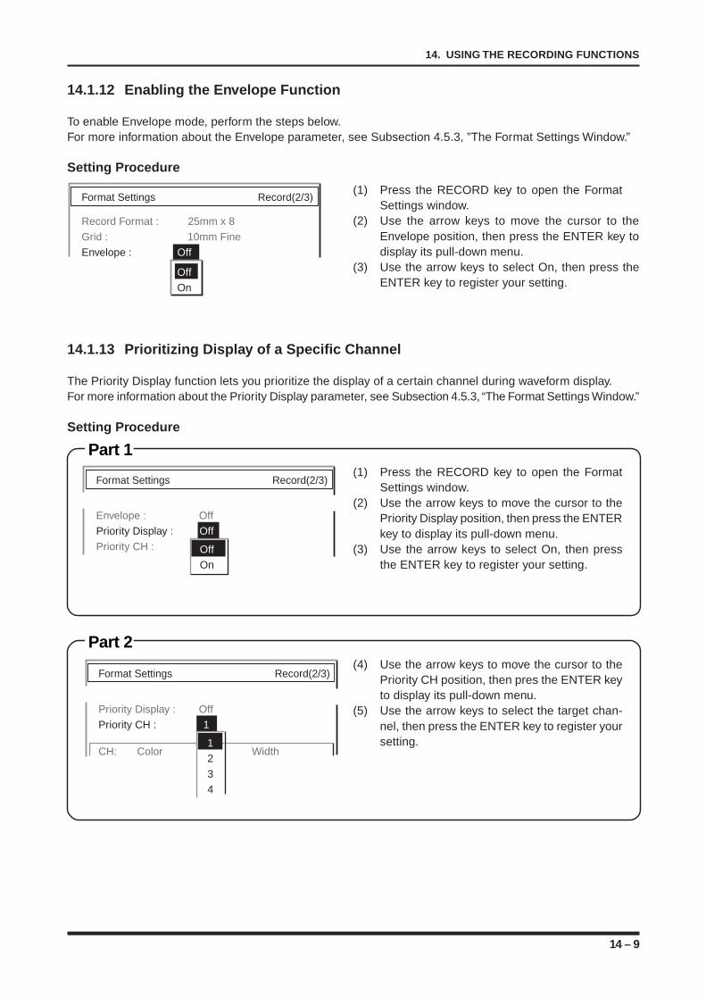
14 – 9
14. USING THE RECORDING FUNCTIONS
14.1.13 Prioritizing Display of a Specific Channel
The Priority Display function lets you prioritize the display of a certain channel during waveform display.For more information about the Priority Display parameter, see Subsection 4.5.3, “The Format Settings Window.”
Setting Procedure
Part 1(1) Press the RECORD key to open the Format
Settings window.(2) Use the arrow keys to move the cursor to the
Priority Display position, then press the ENTERkey to display its pull-down menu.
(3) Use the arrow keys to select On, then pressthe ENTER key to register your setting.
Part 2(4) Use the arrow keys to move the cursor to the
Priority CH position, then pres the ENTER keyto display its pull-down menu.
(5) Use the arrow keys to select the target chan-nel, then press the ENTER key to register yoursetting.
Format Settings Record(2/3)
Envelope : Off
Priority Display : Off
Priority CH : Off
On
Format Settings Record(2/3)
Priority Display : Off
Priority CH : 1
CH: Color Zone Width1
2
3
4
14.1.12 Enabling the Envelope Function
To enable Envelope mode, perform the steps below.For more information about the Envelope parameter, see Subsection 4.5.3, ”The Format Settings Window.”
Setting Procedure
(1) Press the RECORD key to open the FormatSettings window.
(2) Use the arrow keys to move the cursor to theEnvelope position, then press the ENTER key todisplay its pull-down menu.
(3) Use the arrow keys to select On, then press theENTER key to register your setting.
Format Settings Record(2/3)
Record Format : 25mm x 8
Grid : 10mm Fine
Envelope : Off
OffOn
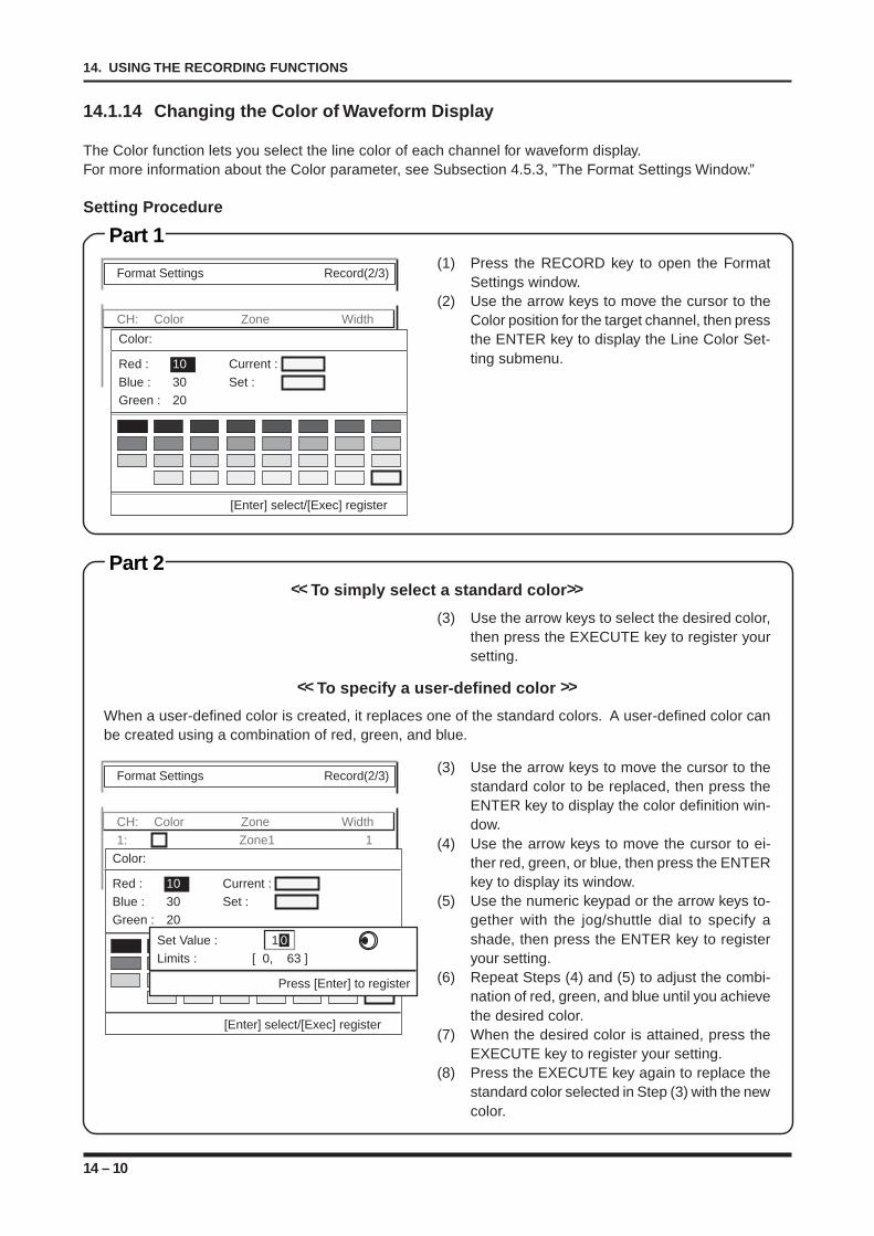
14 – 10
14. USING THE RECORDING FUNCTIONS
14.1.14 Changing the Color of Waveform Display
The Color function lets you select the line color of each channel for waveform display.For more information about the Color parameter, see Subsection 4.5.3, ”The Format Settings Window.”
Setting Procedure
Part 1(1) Press the RECORD key to open the Format
Settings window.(2) Use the arrow keys to move the cursor to the
Color position for the target channel, then pressthe ENTER key to display the Line Color Set-ting submenu.
Part 2<< To simply select a standard color >>
(3) Use the arrow keys to select the desired color,then press the EXECUTE key to register yoursetting.
<< To specify a user-defined color >>
When a user-defined color is created, it replaces one of the standard colors. A user-defined color canbe created using a combination of red, green, and blue.
(3) Use the arrow keys to move the cursor to thestandard color to be replaced, then press theENTER key to display the color definition win-dow.
(4) Use the arrow keys to move the cursor to ei-ther red, green, or blue, then press the ENTERkey to display its window.
(5) Use the numeric keypad or the arrow keys to-gether with the jog/shuttle dial to specify ashade, then press the ENTER key to registeryour setting.
(6) Repeat Steps (4) and (5) to adjust the combi-nation of red, green, and blue until you achievethe desired color.
(7) When the desired color is attained, press theEXECUTE key to register your setting.
(8) Press the EXECUTE key again to replace thestandard color selected in Step (3) with the newcolor.
Format Settings Record(2/3)
CH: Color Zone Width
1: Zone1 1
2: Zone2 1
[Enter] select/[Exec] register
Color:
Red : 10 Current :Blue : 30 Set :Green : 20
Format Settings Record(2/3)
CH: Color Zone Width
1: Zone1 1
2: Zone2 1
[Enter] select/[Exec] register
Color:
Red : 10 Current :Blue : 30 Set :Green : 20
Set Value : 1 0Limits : [ 0, 63 ]
Press [Enter] to register
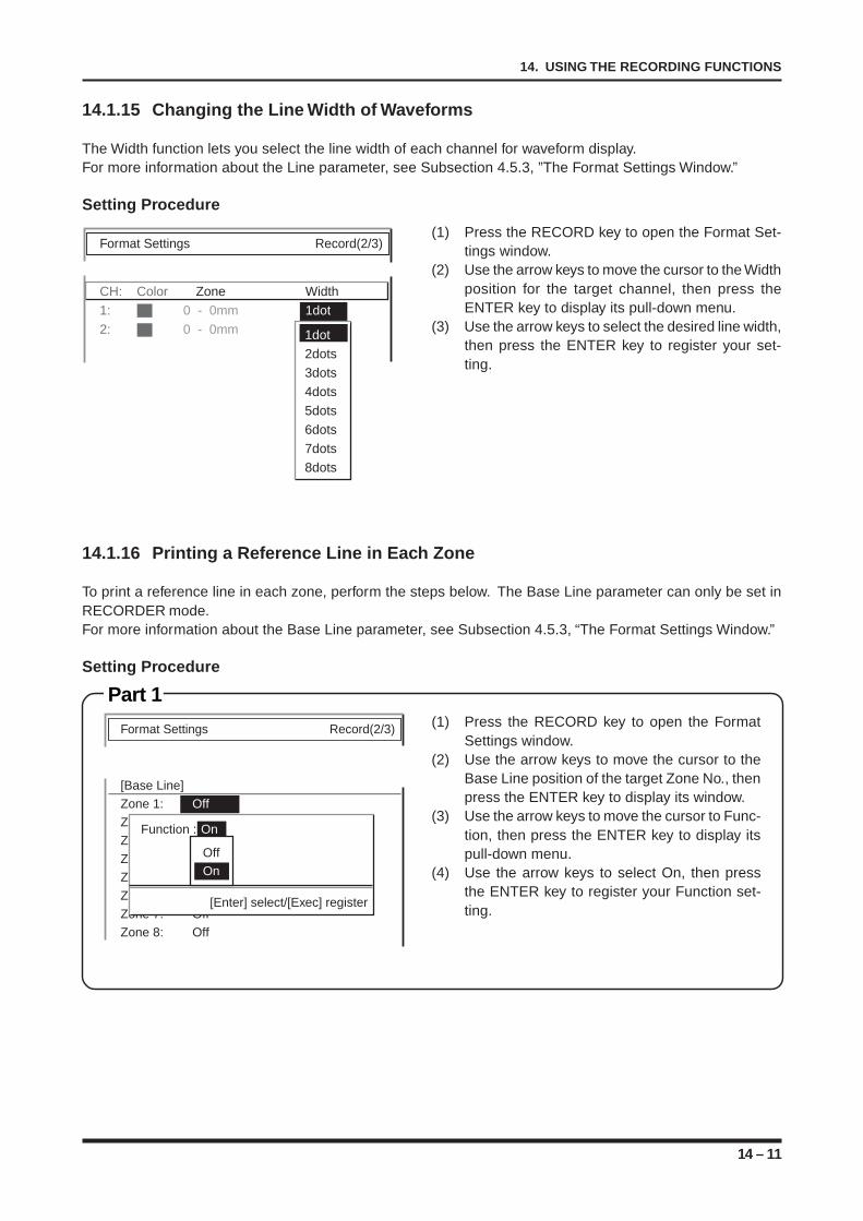
14 – 11
14. USING THE RECORDING FUNCTIONS
14.1.15 Changing the Line Width of Waveforms
The Width function lets you select the line width of each channel for waveform display.For more information about the Line parameter, see Subsection 4.5.3, ”The Format Settings Window.”
Setting Procedure
(1) Press the RECORD key to open the Format Set-tings window.
(2) Use the arrow keys to move the cursor to the Widthposition for the target channel, then press theENTER key to display its pull-down menu.
(3) Use the arrow keys to select the desired line width,then press the ENTER key to register your set-ting.
14.1.16 Printing a Reference Line in Each Zone
To print a reference line in each zone, perform the steps below. The Base Line parameter can only be set inRECORDER mode.For more information about the Base Line parameter, see Subsection 4.5.3, “The Format Settings Window.”
Setting Procedure
Part 1(1) Press the RECORD key to open the Format
Settings window.(2) Use the arrow keys to move the cursor to the
Base Line position of the target Zone No., thenpress the ENTER key to display its window.
(3) Use the arrow keys to move the cursor to Func-tion, then press the ENTER key to display itspull-down menu.
(4) Use the arrow keys to select On, then pressthe ENTER key to register your Function set-ting.
Format Settings Record(2/3)
CH: Color Zone Width
1: 0 - 0mm 1dot
2: 0 - 0mm 1do1dot
2dots
3dots
4dots
5dots
6dots
7dots
8dots
Format Settings Record(2/3)
[Base Line]
Zone 1: Off
Zone 2: + 50.0%
Zone 3: + 80.0%
Zone 4: + 10.0%
Zone 5: Off
Zone 6: Off
Zone 7: Off
Zone 8: Off
Function : On
[Enter] select/[Exec] register
OffOn
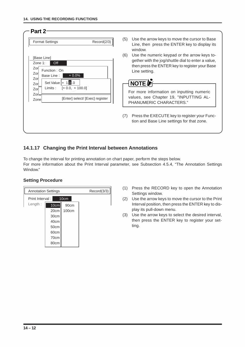
14 – 12
14. USING THE RECORDING FUNCTIONS
Format Settings Record(2/3)
[Base Line]
Zone 1: Off
Zone 2:
Zone 3:
Zone 4:
Zone 5: Off
Zone 6: Off
Zone 7: Off
Zone 8: Off
Function : OnBase Line
[+ 1.000V]
[Enter] select/ [Exec] register
: + 0.0%
Set Value + 1 0 .0Limits : [+ 0.0, + 100.0]
[Enter] select/ [Exec] register
Part 2(5) Use the arrow keys to move the cursor to Base
Line, then press the ENTER key to display itswindow.
(6) Use the numeric keypad or the arrow keys to-gether with the jog/shuttle dial to enter a value,then press the ENTER key to register your BaseLine setting.
NOTEFor more information on inputting numericvalues, see Chapter 19, ”INPUTTING AL-PHANUMERIC CHARACTERS.”
(7) Press the EXECUTE key to register your Func-tion and Base Line settings for that zone.
14.1.17 Changing the Print Interval between Annotations
To change the interval for printing annotation on chart paper, perform the steps below.For more information about the Print Interval parameter, see Subsection 4.5.4, “The Annotation SettingsWindow.”
Setting Procedure
(1) Press the RECORD key to open the AnnotationSettings window.
(2) Use the arrow keys to move the cursor to the PrintInterval position, then press the ENTER key to dis-play its pull-down menu.
(3) Use the arrow keys to select the desired interval,then press the ENTER key to register your set-ting.
Annotation Settings Record(3/3)
Print Interval : 10cm
Length : 3210cm 90cm
20cm 100cm
30cm
40cm
50cm
60cm
70cm
80cm
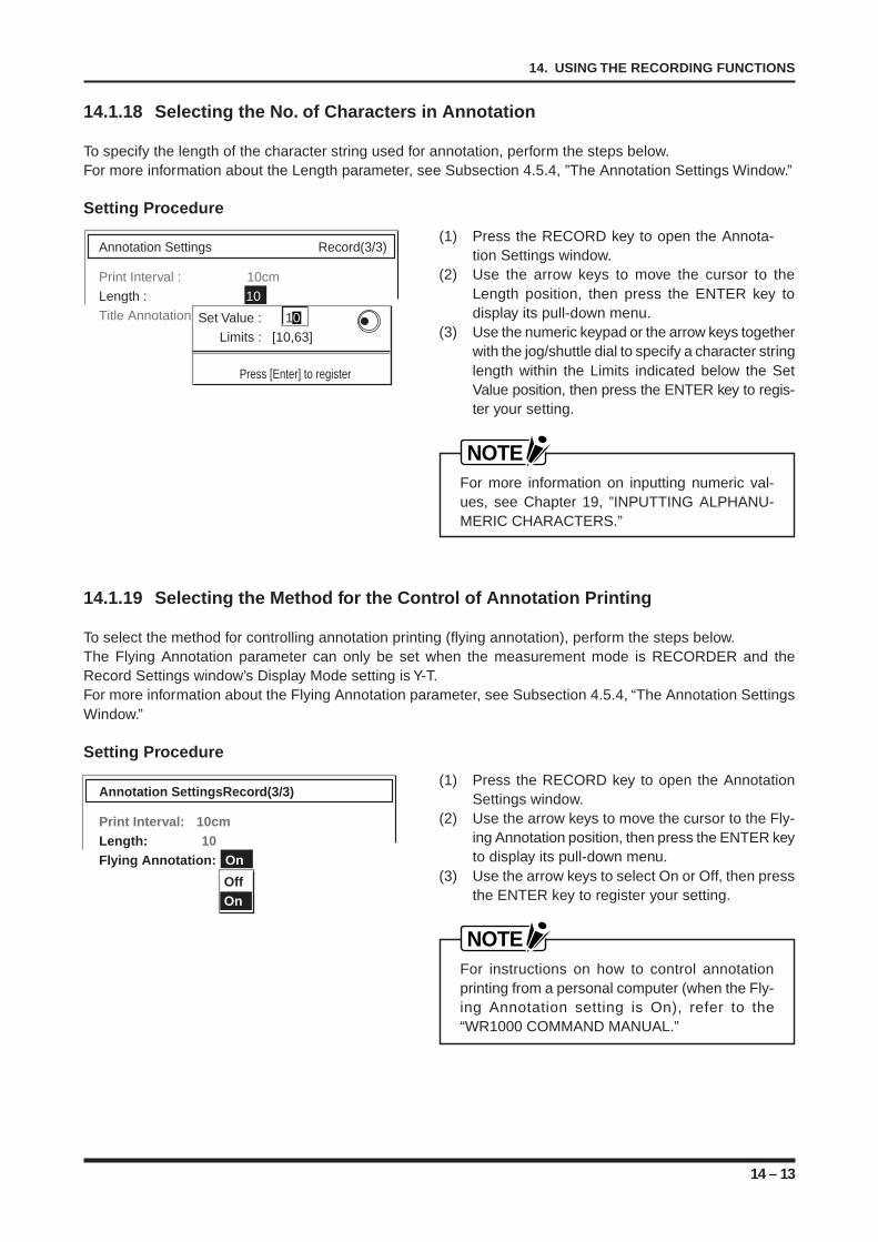
14 – 13
14. USING THE RECORDING FUNCTIONS
14.1.18 Selecting the No. of Characters in Annotation
To specify the length of the character string used for annotation, perform the steps below.For more information about the Length parameter, see Subsection 4.5.4, ”The Annotation Settings Window.”
Setting Procedure
(1) Press the RECORD key to open the Annota-tion Settings window.
(2) Use the arrow keys to move the cursor to theLength position, then press the ENTER key todisplay its pull-down menu.
(3) Use the numeric keypad or the arrow keys togetherwith the jog/shuttle dial to specify a character stringlength within the Limits indicated below the SetValue position, then press the ENTER key to regis-ter your setting.
NOTEFor more information on inputting numeric val-ues, see Chapter 19, ”INPUTTING ALPHANU-MERIC CHARACTERS.”
14.1.19 Selecting the Method for the Control of Annotation Printing
To select the method for controlling annotation printing (flying annotation), perform the steps below.The Flying Annotation parameter can only be set when the measurement mode is RECORDER and theRecord Settings window’s Display Mode setting is Y-T.For more information about the Flying Annotation parameter, see Subsection 4.5.4, “The Annotation SettingsWindow.”
Setting Procedure
(1) Press the RECORD key to open the AnnotationSettings window.
(2) Use the arrow keys to move the cursor to the Fly-ing Annotation position, then press the ENTER keyto display its pull-down menu.
(3) Use the arrow keys to select On or Off, then pressthe ENTER key to register your setting.
NOTEFor instructions on how to control annotationprinting from a personal computer (when the Fly-ing Annotation setting is On), refer to the“WR1000 COMMAND MANUAL.”
Annotation Settings Record(3/3)
Print Interval : 10cm
Length : 10
Title Annotation :Set Value : 10
Limits : [10,63]
Press [Enter] to register
Annotation SettingsRecord(3/3)
Print Interval: 10cmLength: 10Flying Annotation: On
OffOn
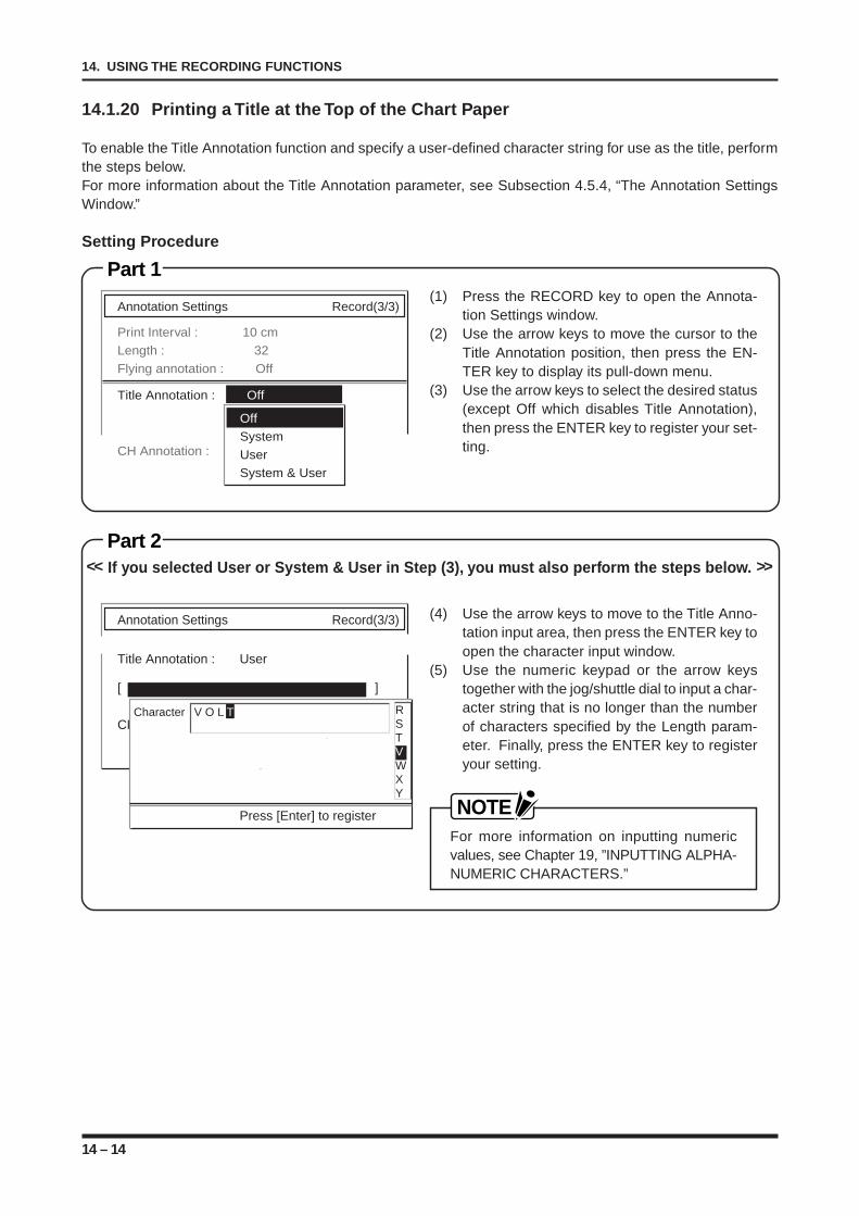
14 – 14
14. USING THE RECORDING FUNCTIONS
14.1.20 Printing a Title at the Top of the Chart Paper
To enable the Title Annotation function and specify a user-defined character string for use as the title, performthe steps below.For more information about the Title Annotation parameter, see Subsection 4.5.4, “The Annotation SettingsWindow.”
Setting Procedure
Part 1(1) Press the RECORD key to open the Annota-
tion Settings window.(2) Use the arrow keys to move the cursor to the
Title Annotation position, then press the EN-TER key to display its pull-down menu.
(3) Use the arrow keys to select the desired status(except Off which disables Title Annotation),then press the ENTER key to register your set-ting.
Part 2<< If you selected User or System & User in Step (3), you must also perform the steps below. >>
(4) Use the arrow keys to move to the Title Anno-tation input area, then press the ENTER key toopen the character input window.
(5) Use the numeric keypad or the arrow keystogether with the jog/shuttle dial to input a char-acter string that is no longer than the numberof characters specified by the Length param-eter. Finally, press the ENTER key to registeryour setting.
NOTEFor more information on inputting numericvalues, see Chapter 19, ”INPUTTING ALPHA-NUMERIC CHARACTERS.”
Annotation Settings Record(3/3)
Print Interval : 10 cm
Length : 32
Flying annotation : Off
Title Annotation : Off
CH Annotation :
Off
System
User
System & User
Annotation Settings Record(3/3)
Title Annotation : User
[ ]
CHCharacter V O L T
Press [Enter] to register
RSTVWXY
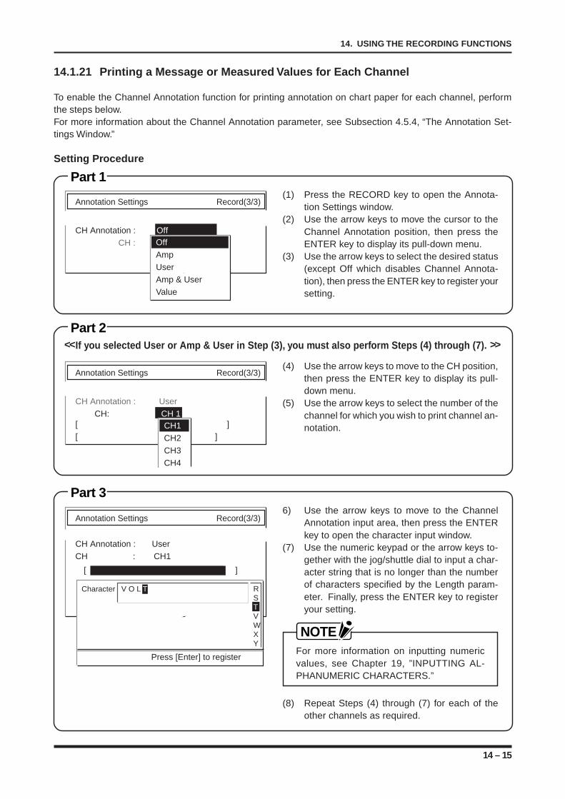
14 – 15
14. USING THE RECORDING FUNCTIONS
14.1.21 Printing a Message or Measured Values for Each Channel
To enable the Channel Annotation function for printing annotation on chart paper for each channel, performthe steps below.For more information about the Channel Annotation parameter, see Subsection 4.5.4, “The Annotation Set-tings Window.”
Setting Procedure
Part 1(1) Press the RECORD key to open the Annota-
tion Settings window.(2) Use the arrow keys to move the cursor to the
Channel Annotation position, then press theENTER key to display its pull-down menu.
(3) Use the arrow keys to select the desired status(except Off which disables Channel Annota-tion), then press the ENTER key to register yoursetting.
Part 2<<If you selected User or Amp & User in Step (3), you must also perform Steps (4) through (7). >>
(4) Use the arrow keys to move to the CH position,then press the ENTER key to display its pull-down menu.
(5) Use the arrow keys to select the number of thechannel for which you wish to print channel an-notation.
Part 36) Use the arrow keys to move to the Channel
Annotation input area, then press the ENTERkey to open the character input window.
(7) Use the numeric keypad or the arrow keys to-gether with the jog/shuttle dial to input a char-acter string that is no longer than the numberof characters specified by the Length param-eter. Finally, press the ENTER key to registeryour setting.
NOTEFor more information on inputting numericvalues, see Chapter 19, ”INPUTTING AL-PHANUMERIC CHARACTERS.”
(8) Repeat Steps (4) through (7) for each of theother channels as required.
Annotation Settings Record(3/3)
CH Annotation : Off
CH : Off
Amp
User
Amp & User
Value
Annotation Settings Record(3/3)
CH Annotation : User
CH: CH 1[ ]
[ ]CH1
CH2
CH3
CH4
Annotation Settings Record(3/3)
CH Annotation : User
CH : CH1
Character V O L T
Press [Enter] to register
RSTVWXY
[ ]
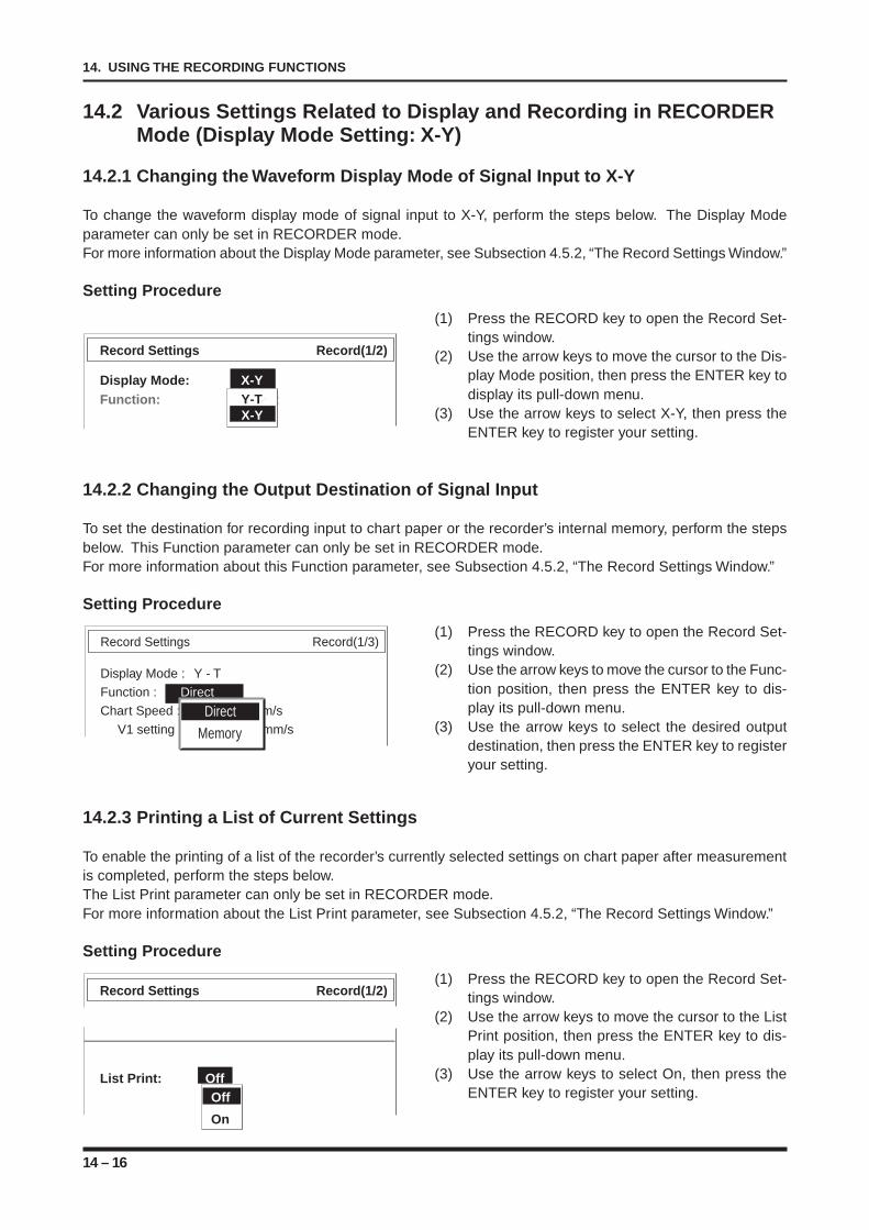
14 – 16
14. USING THE RECORDING FUNCTIONS
14.2 Various Settings Related to Display and Recording in RECORDERMode (Display Mode Setting: X-Y)
14.2.1 Changing the Waveform Display Mode of Signal Input to X-Y
To change the waveform display mode of signal input to X-Y, perform the steps below. The Display Modeparameter can only be set in RECORDER mode.For more information about the Display Mode parameter, see Subsection 4.5.2, “The Record Settings Window.”
Setting Procedure
(1) Press the RECORD key to open the Record Set-tings window.
(2) Use the arrow keys to move the cursor to the Dis-play Mode position, then press the ENTER key todisplay its pull-down menu.
(3) Use the arrow keys to select X-Y, then press theENTER key to register your setting.
14.2.2 Changing the Output Destination of Signal Input
To set the destination for recording input to chart paper or the recorder’s internal memory, perform the stepsbelow. This Function parameter can only be set in RECORDER mode.For more information about this Function parameter, see Subsection 4.5.2, “The Record Settings Window.”
Setting Procedure
(1) Press the RECORD key to open the Record Set-tings window.
(2) Use the arrow keys to move the cursor to the Func-tion position, then press the ENTER key to dis-play its pull-down menu.
(3) Use the arrow keys to select the desired outputdestination, then press the ENTER key to registeryour setting.
14.2.3 Printing a List of Current Settings
To enable the printing of a list of the recorder’s currently selected settings on chart paper after measurementis completed, perform the steps below.The List Print parameter can only be set in RECORDER mode.For more information about the List Print parameter, see Subsection 4.5.2, “The Record Settings Window.”
Setting Procedure
(1) Press the RECORD key to open the Record Set-tings window.
(2) Use the arrow keys to move the cursor to the ListPrint position, then press the ENTER key to dis-play its pull-down menu.
(3) Use the arrow keys to select On, then press theENTER key to register your setting.
Record Settings Record(1/2)
List Print: OffOff
On
Record Settings Record(1/3)
Display Mode : Y - T
Function : Direct
Chart Speed : 20mm/s
V1 setting : 10 mm/s Direct
Memory
Record Settings Record(1/2)
Display Mode: X-YFunction: DirectY-T
X-Y
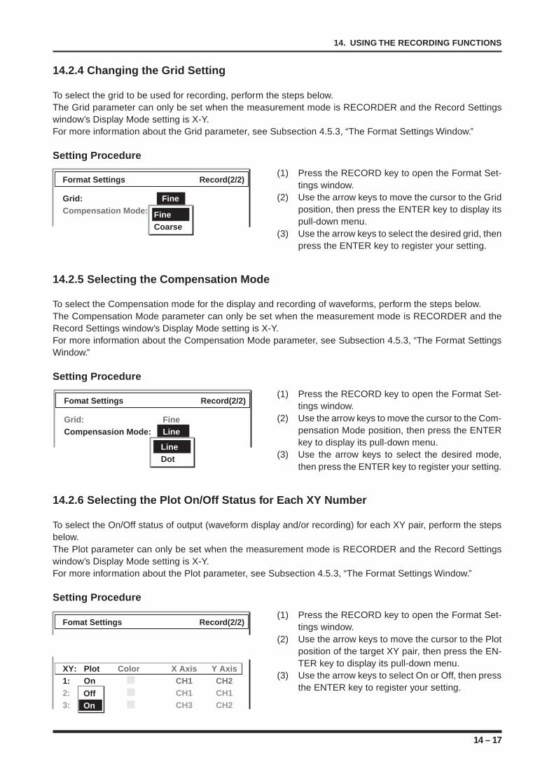
14 – 17
14. USING THE RECORDING FUNCTIONS
14.2.4 Changing the Grid Setting
To select the grid to be used for recording, perform the steps below.The Grid parameter can only be set when the measurement mode is RECORDER and the Record Settingswindow’s Display Mode setting is X-Y.For more information about the Grid parameter, see Subsection 4.5.3, “The Format Settings Window.”
Setting Procedure
(1) Press the RECORD key to open the Format Set-tings window.
(2) Use the arrow keys to move the cursor to the Gridposition, then press the ENTER key to display itspull-down menu.
(3) Use the arrow keys to select the desired grid, thenpress the ENTER key to register your setting.
14.2.5 Selecting the Compensation Mode
To select the Compensation mode for the display and recording of waveforms, perform the steps below.The Compensation Mode parameter can only be set when the measurement mode is RECORDER and theRecord Settings window’s Display Mode setting is X-Y.For more information about the Compensation Mode parameter, see Subsection 4.5.3, “The Format SettingsWindow.”
Setting Procedure
(1) Press the RECORD key to open the Format Set-tings window.
(2) Use the arrow keys to move the cursor to the Com-pensation Mode position, then press the ENTERkey to display its pull-down menu.
(3) Use the arrow keys to select the desired mode,then press the ENTER key to register your setting.
14.2.6 Selecting the Plot On/Off Status for Each XY Number
To select the On/Off status of output (waveform display and/or recording) for each XY pair, perform the stepsbelow.The Plot parameter can only be set when the measurement mode is RECORDER and the Record Settingswindow’s Display Mode setting is X-Y.For more information about the Plot parameter, see Subsection 4.5.3, “The Format Settings Window.”
Setting Procedure
(1) Press the RECORD key to open the Format Set-tings window.
(2) Use the arrow keys to move the cursor to the Plotposition of the target XY pair, then press the EN-TER key to display its pull-down menu.
(3) Use the arrow keys to select On or Off, then pressthe ENTER key to register your setting.
Format Settings Record(2/2)
Grid: FineCompensation Mode: LineFine
Coarse
Fomat Settings Record(2/2)
Grid: FineCompensasion Mode: Line
LineDot
Fomat Settings Record(2/2)
XY: Plot Color X Axis Y Axis1: On CH1 CH22: Off CH1 CH13: Off CH3 CH2
OffOn
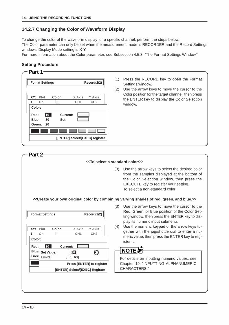
14 – 18
14. USING THE RECORDING FUNCTIONS
14.2.7 Changing the Color of Waveform Display
To change the color of the waveform display for a specific channel, perform the steps below.The Color parameter can only be set when the measurement mode is RECORDER and the Record Settingswindow’s Display Mode setting is X-Y.For more information about the Color parameter, see Subsection 4.5.3, “The Format Settings Window.”
Setting Procedure
Part 1(1) Press the RECORD key to open the Format
Settings window.(2) Use the arrow keys to move the cursor to the
Color position for the target channel, then pressthe ENTER key to display the Color Selectionwindow.
Part 2<<To select a standard color: >>
(3) Use the arrow keys to select the desired colorfrom the samples displayed at the bottom ofthe Color Selection window, then press theEXECUTE key to register your setting.To select a non-standard color:
<<Create your own original color by combining varying shades of red, green, and blue.>>
(3) Use the arrow keys to move the cursor to theRed, Green, or Blue position of the Color Set-ting window, then press the ENTER key to dis-play its numeric input submenu.
(4) Use the numeric keypad or the arrow keys to-gether with the jog/shuttle dial to enter a nu-meric value, then press the ENTER key to reg-ister it.
NOTEFor details on inputting numeric values, seeChapter 19, “INPUTTING ALPHANUMERICCHARACTERS.”
Fomat Settings Record(2/2)
XY: Plot Color X Axis Y Axis1: On CH1 CH22: Off CH1 CH13: Off CH3 CH2
[ENTER] select/[EXEC] register
Color:
Red: 10 Current:Blue: 30 Set:Green: 20
Format Settings Record(2/2)
XY: Plot Color X Axis Y Axis1: On CH1 CH22: Off CH1 CH13: Off CH3 CH2
[ENTER] Select/[EXEC] Register
Color:
Red: 10 Current:Blue: 30 Set:Green: 20
Set Value: 10Limits: [ 0, 63]
Press [ENTER] to register
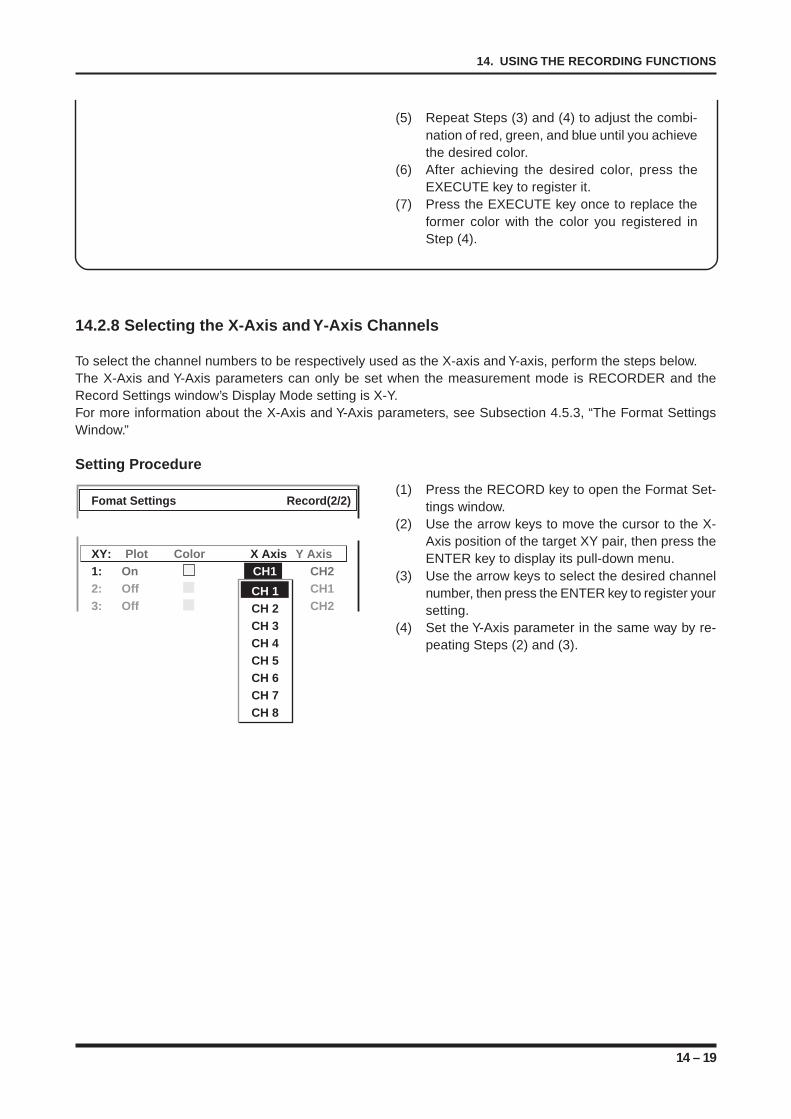
14 – 19
14. USING THE RECORDING FUNCTIONS
(5) Repeat Steps (3) and (4) to adjust the combi-nation of red, green, and blue until you achievethe desired color.
(6) After achieving the desired color, press theEXECUTE key to register it.
(7) Press the EXECUTE key once to replace theformer color with the color you registered inStep (4).
14.2.8 Selecting the X-Axis and Y-Axis Channels
To select the channel numbers to be respectively used as the X-axis and Y-axis, perform the steps below.The X-Axis and Y-Axis parameters can only be set when the measurement mode is RECORDER and theRecord Settings window’s Display Mode setting is X-Y.For more information about the X-Axis and Y-Axis parameters, see Subsection 4.5.3, “The Format SettingsWindow.”
Setting Procedure
(1) Press the RECORD key to open the Format Set-tings window.
(2) Use the arrow keys to move the cursor to the X-Axis position of the target XY pair, then press theENTER key to display its pull-down menu.
(3) Use the arrow keys to select the desired channelnumber, then press the ENTER key to register yoursetting.
(4) Set the Y-Axis parameter in the same way by re-peating Steps (2) and (3).
Fomat Settings Record(2/2)
XY: Plot Color X Axis Y Axis1: On CH1 CH22: Off CH1 CH13: Off CH3 CH2
CH 1CH 2CH 3CH 4CH 5CH 6CH 7CH 8
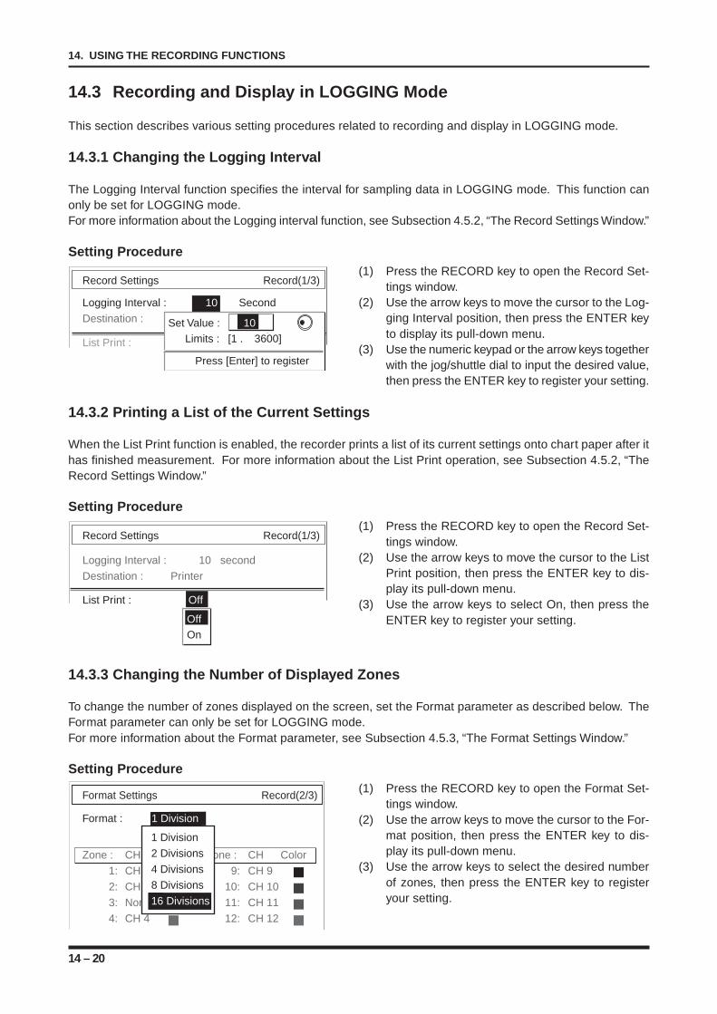
14 – 20
14. USING THE RECORDING FUNCTIONS
Format Settings Record(2/3)
Format : 1 Division
Zone : CH Zone : CH Color
1: CH 1 9: CH 9
2: CH 2 10: CH 10
3: None 11: CH 11
4: CH 4 12: CH 12
1 Division
2 Divisions
4 Divisions
8 Divisions
16 Divisions
Record Settings Record(1/3)
Logging Interval : 10 second
Destination : Printer
List Print : Off
OffOn
Record Settings Record(1/3)
Logging Interval : 10 Second
Destination :
List Print : V1
Set Value : 10Limits : [1 . 3600]
Press [Enter] to register
14.3 Recording and Display in LOGGING Mode
This section describes various setting procedures related to recording and display in LOGGING mode.
14.3.1 Changing the Logging Interval
The Logging Interval function specifies the interval for sampling data in LOGGING mode. This function canonly be set for LOGGING mode.For more information about the Logging interval function, see Subsection 4.5.2, “The Record Settings Window.”
Setting Procedure(1) Press the RECORD key to open the Record Set-
tings window.(2) Use the arrow keys to move the cursor to the Log-
ging Interval position, then press the ENTER keyto display its pull-down menu.
(3) Use the numeric keypad or the arrow keys togetherwith the jog/shuttle dial to input the desired value,then press the ENTER key to register your setting.
14.3.2 Printing a List of the Current Settings
When the List Print function is enabled, the recorder prints a list of its current settings onto chart paper after ithas finished measurement. For more information about the List Print operation, see Subsection 4.5.2, “TheRecord Settings Window.”
Setting Procedure(1) Press the RECORD key to open the Record Set-
tings window.(2) Use the arrow keys to move the cursor to the List
Print position, then press the ENTER key to dis-play its pull-down menu.
(3) Use the arrow keys to select On, then press theENTER key to register your setting.
14.3.3 Changing the Number of Displayed Zones
To change the number of zones displayed on the screen, set the Format parameter as described below. TheFormat parameter can only be set for LOGGING mode.For more information about the Format parameter, see Subsection 4.5.3, “The Format Settings Window.”
Setting Procedure(1) Press the RECORD key to open the Format Set-
tings window.(2) Use the arrow keys to move the cursor to the For-
mat position, then press the ENTER key to dis-play its pull-down menu.
(3) Use the arrow keys to select the desired numberof zones, then press the ENTER key to registeryour setting.
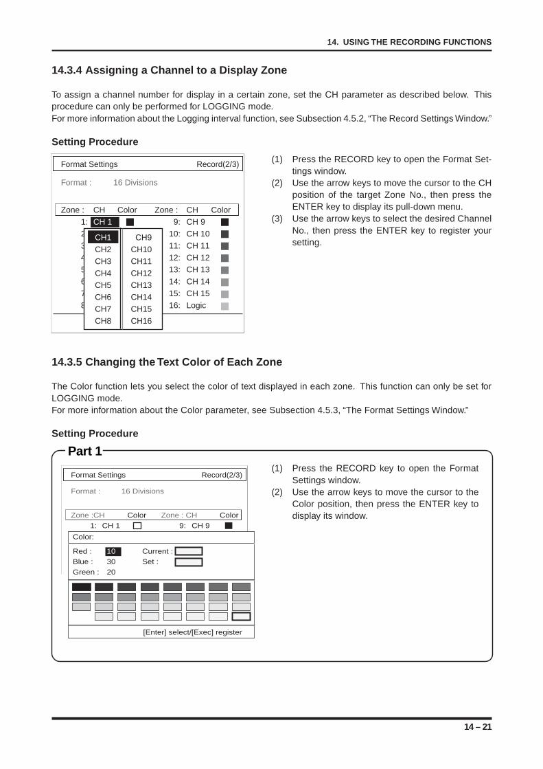
14 – 21
14. USING THE RECORDING FUNCTIONS
14.3.5 Changing the Text Color of Each Zone
The Color function lets you select the color of text displayed in each zone. This function can only be set forLOGGING mode.For more information about the Color parameter, see Subsection 4.5.3, “The Format Settings Window.”
Setting Procedure
Part 1(1) Press the RECORD key to open the Format
Settings window.(2) Use the arrow keys to move the cursor to the
Color position, then press the ENTER key todisplay its window.
Format Settings Record(2/3)
Format : 16 Divisions
Zone : CH Color Zone : CH Color
1: CH 1 9: CH 9
2: CH 2 10: CH 10
3: None 11: CH 11
4: CH 4 12: CH 12
5: CH 5 13: CH 13
6: CH 6 14: CH 14
7: CH 7 15: CH 15
8: CH 8 16: Logic
CH1 CH9
CH2 CH10
CH3 CH11
CH4 CH12
CH5 CH13
CH6 CH14
CH7 CH15
CH8 CH16
14.3.4 Assigning a Channel to a Display Zone
To assign a channel number for display in a certain zone, set the CH parameter as described below. Thisprocedure can only be performed for LOGGING mode.For more information about the Logging interval function, see Subsection 4.5.2, “The Record Settings Window.”
Setting Procedure
(1) Press the RECORD key to open the Format Set-tings window.
(2) Use the arrow keys to move the cursor to the CHposition of the target Zone No., then press theENTER key to display its pull-down menu.
(3) Use the arrow keys to select the desired ChannelNo., then press the ENTER key to register yoursetting.
Format Settings Record(2/3)
Format : 16 Divisions
Zone :CH Color Zone : CH Color
1: CH 1 9: CH 9
[Enter] select/[Exec] register
Color:
Red : 10 Current :Blue : 30 Set :Green : 20
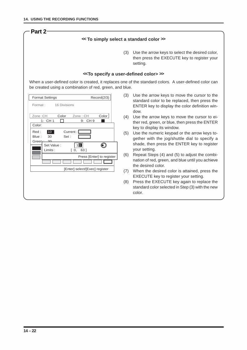
14 – 22
14. USING THE RECORDING FUNCTIONS
Format Settings Record(2/3)
Format : 16 Divisions
Zone :CH Color Zone : CH Color
1: CH 1 9: CH 9
[Enter] select/[Exec] register
Color:
Red : 10 Current :Blue : 30 Set :Green : 20
Set Value : 1 0Limits : [ 0, 63 ]
Press [Enter] to register
Part 2<< To simply select a standard color >>
(3) Use the arrow keys to select the desired color,then press the EXECUTE key to register yoursetting.
<<To specify a user-defined color> >>
When a user-defined color is created, it replaces one of the standard colors. A user-defined color canbe created using a combination of red, green, and blue.
(3) Use the arrow keys to move the cursor to thestandard color to be replaced, then press theENTER key to display the color definition win-dow.
(4) Use the arrow keys to move the cursor to ei-ther red, green, or blue, then press the ENTERkey to display its window.
(5) Use the numeric keypad or the arrow keys to-gether with the jog/shuttle dial to specify ashade, then press the ENTER key to registeryour setting.
(6) Repeat Steps (4) and (5) to adjust the combi-nation of red, green, and blue until you achievethe desired color.
(7) When the desired color is attained, press theEXECUTE key to register your setting.
(8) Press the EXECUTE key again to replace thestandard color selected in Step (3) with the newcolor.
15 – 1
15. SETTING THE WAVEFORM JUDGEMENT FUNCTIONS
CHAPTER 15CHAPTER 15SETTING THE WAVEFORM JUDGEMENTFUNCTIONS
This chapter describes the overall flow for setting proce-dures involving waveform judgement.
15.1 Performing a Waveform Judgement Operation duringDIRECT Measurement
15.2 Performing a Waveform Judgement Operation duringMEMORY Measurement
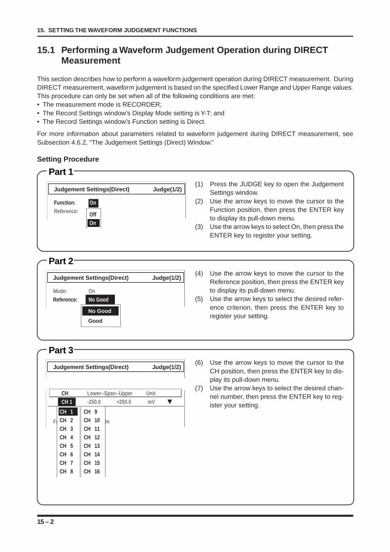
15 – 2
15. SETTING THE WAVEFORM JUDGEMENT FUNCTIONS
15.1 Performing a Waveform Judgement Operation during DIRECTMeasurement
This section describes how to perform a waveform judgement operation during DIRECT measurement. DuringDIRECT measurement, waveform judgement is based on the specified Lower Range and Upper Range values.This procedure can only be set when all of the following conditions are met:• The measurement mode is RECORDER;• The Record Settings window’s Display Mode setting is Y-T; and• The Record Settings window’s Function setting is Direct.
For more information about parameters related to waveform judgement during DIRECT measurement, seeSubsection 4.6.2, “The Judgement Settings (Direct) Window.”
Setting Procedure
Part 1(1) Press the JUDGE key to open the Judgement
Settings window.(2) Use the arrow keys to move the cursor to the
Function position, then press the ENTER keyto display its pull-down menu.
(3) Use the arrow keys to select On, then press theENTER key to register your setting.
Part 2(4) Use the arrow keys to move the cursor to the
Reference position, then press the ENTER keyto display its pull-down menu.
(5) Use the arrow keys to select the desired refer-ence criterion, then press the ENTER key toregister your setting.
Part 3(6) Use the arrow keys to move the cursor to the
CH position, then press the ENTER key to dis-play its pull-down menu.
(7) Use the arrow keys to select the desired chan-nel number, then press the ENTER key to reg-ister your setting.
Judgement Settings(Direct) Judge(1/2)
Function:Reference: Off
On
On
Judgement Settings(Direct) Judge(1/2)
Mode: OnReference: No Good
No Good
Good
Judgement Settings(Direct) Judge(1/2)
CH Lower--Span--Upper UnitCH 1 -250.0 +250.0 mV
Function: On
CH 1 CH 9CH 2 CH 10CH 3 CH 11CH 4 CH 12CH 5 CH 13CH 6 CH 14CH 7 CH 15CH 8 CH 16
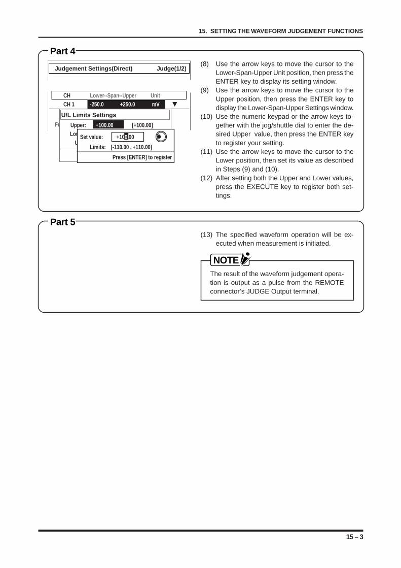
15 – 3
15. SETTING THE WAVEFORM JUDGEMENT FUNCTIONS
Part 4(8) Use the arrow keys to move the cursor to the
Lower-Span-Upper Unit position, then press theENTER key to display its setting window.
(9) Use the arrow keys to move the cursor to theUpper position, then press the ENTER key todisplay the Lower-Span-Upper Settings window.
(10) Use the numeric keypad or the arrow keys to-gether with the jog/shuttle dial to enter the de-sired Upper value, then press the ENTER keyto register your setting.
(11) Use the arrow keys to move the cursor to theLower position, then set its value as describedin Steps (9) and (10).
(12) After setting both the Upper and Lower values,press the EXECUTE key to register both set-tings.
Part 5(13) The specified waveform operation will be ex-
ecuted when measurement is initiated.
NOTEThe result of the waveform judgement opera-tion is output as a pulse from the REMOTEconnector’s JUDGE Output terminal.
Judgement Settings(Direct) Judge(1/2)
CH Lower--Span--Upper UnitCH 1 -250.0 +250.0 mV
Function: On
U/L Limits Settings
Upper: +100.00 [+100.00]Lower: -100.00 [-100.00]
Unit: [mV ] [mV ]
[ENTER]select / [EXEC]register
Set value: +100.00
Limits: [-110.00 , +110.00]
Press [ENTER] to register
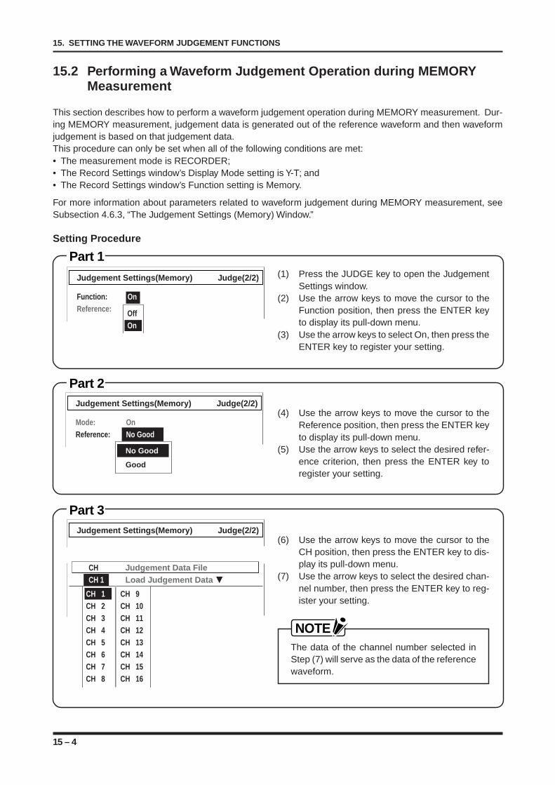
15 – 4
15. SETTING THE WAVEFORM JUDGEMENT FUNCTIONS
15.2 Performing a Waveform Judgement Operation during MEMORYMeasurement
This section describes how to perform a waveform judgement operation during MEMORY measurement. Dur-ing MEMORY measurement, judgement data is generated out of the reference waveform and then waveformjudgement is based on that judgement data.This procedure can only be set when all of the following conditions are met:• The measurement mode is RECORDER;• The Record Settings window’s Display Mode setting is Y-T; and• The Record Settings window’s Function setting is Memory.
For more information about parameters related to waveform judgement during MEMORY measurement, seeSubsection 4.6.3, “The Judgement Settings (Memory) Window.”
Setting Procedure
Part 1(1) Press the JUDGE key to open the Judgement
Settings window.(2) Use the arrow keys to move the cursor to the
Function position, then press the ENTER keyto display its pull-down menu.
(3) Use the arrow keys to select On, then press theENTER key to register your setting.
Part 2
(4) Use the arrow keys to move the cursor to theReference position, then press the ENTER keyto display its pull-down menu.
(5) Use the arrow keys to select the desired refer-ence criterion, then press the ENTER key toregister your setting.
Part 3
(6) Use the arrow keys to move the cursor to theCH position, then press the ENTER key to dis-play its pull-down menu.
(7) Use the arrow keys to select the desired chan-nel number, then press the ENTER key to reg-ister your setting.
NOTEThe data of the channel number selected inStep (7) will serve as the data of the referencewaveform.
Judgement Settings(Memory) Judge(2/2)
CH Judgement Data FileCH 1 Load Judgement Data
CH 1 CH 9CH 2 CH 10CH 3 CH 11CH 4 CH 12CH 5 CH 13CH 6 CH 14CH 7 CH 15CH 8 CH 16
Judgement Settings(Memory) Judge(2/2)
Function:Reference: Off
On
On
Judgement Settings(Memory) Judge(2/2)
Mode: OnReference: No Good
No Good
Good
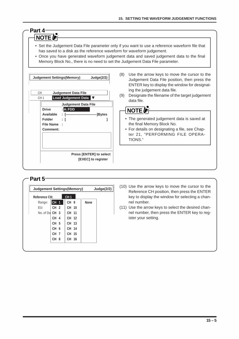
15 – 5
15. SETTING THE WAVEFORM JUDGEMENT FUNCTIONS
Part 4NOTE• Set the Judgement Data File parameter only if you want to use a reference waveform file that
has saved to a disk as the reference waveform for waveform judgement.• Once you have generated waveform judgement data and saved judgement data to the final
Memory Block No., there is no need to set the Judgement Data File parameter.
(8) Use the arrow keys to move the cursor to theJudgement Data File position, then press theENTER key to display the window for designat-ing the judgement data file.
(9) Designate the filename of the target judgementdata file.
NOTE• The generated judgement data is saved at
the final Memory Block No.• For details on designating a file, see Chap-
ter 21, “PERFORMING FILE OPERA-TIONS.”
Part 5(10) Use the arrow keys to move the cursor to the
Reference CH position, then press the ENTERkey to display the window for selecting a chan-nel number.
(11) Use the arrow keys to select the desired chan-nel number, then press the ENTER key to reg-ister your setting.
Judgement Settings(Memory) Judge(2/2)
CH Judgement Data FileCH 1 Load Judgement Data
Judgement Data FileDrive : A:FDDAvailable : [---------------------------]BytesFolder : [ ]File Name :Comment:
Press [ENTER] to select[EXEC] to register
Judgement Settings(Memory) Judge(2/2)
Reference CH: CH 1Range: 500VEU: OffNo. of Data: 2000
CH 1 CH 9 NoneCH 2 CH 10CH 3 CH 11CH 4 CH 12CH 5 CH 13CH 6 CH 14CH 7 CH 15CH 8 CH 16
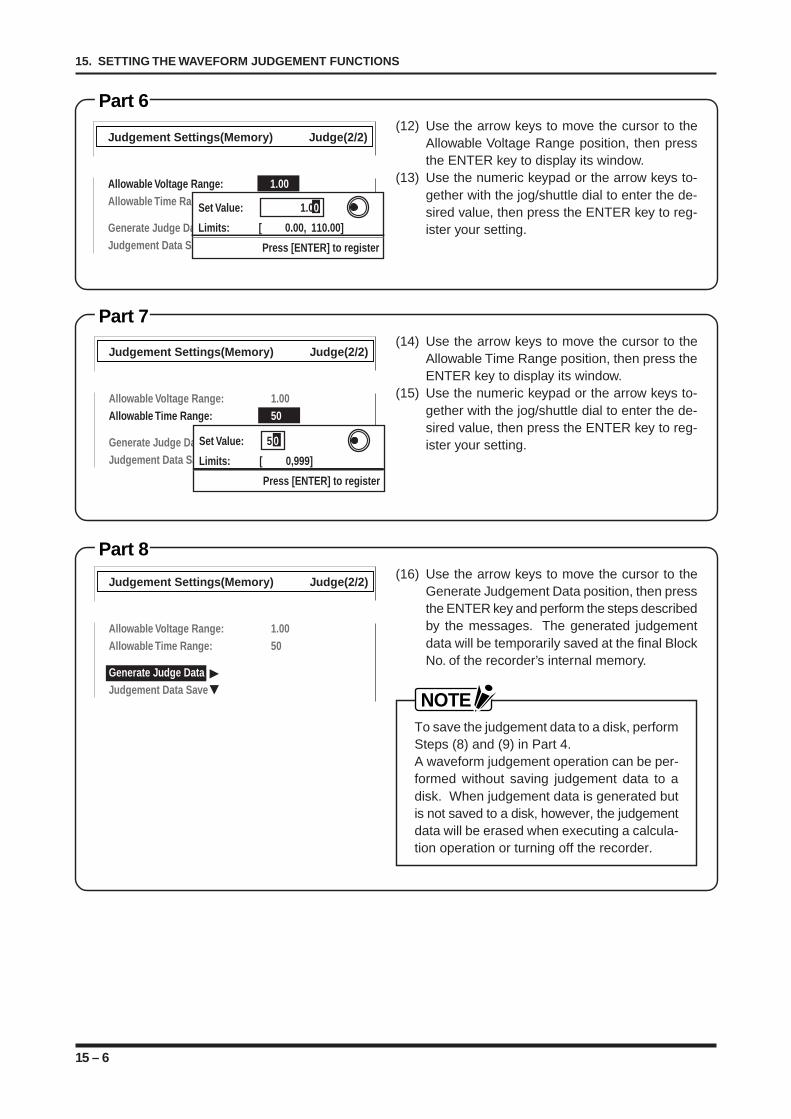
15 – 6
15. SETTING THE WAVEFORM JUDGEMENT FUNCTIONS
Judgement Settings(Memory) Judge(2/2)
Allowable Voltage Range: 1.00Allowable Time Range: 10
Generate Judge DataJudgement Data Save
Set Value: 1.00
Limits: [ 0.00, 110.00]
Press [ENTER] to register
Part 6(12) Use the arrow keys to move the cursor to the
Allowable Voltage Range position, then pressthe ENTER key to display its window.
(13) Use the numeric keypad or the arrow keys to-gether with the jog/shuttle dial to enter the de-sired value, then press the ENTER key to reg-ister your setting.
Part 7(14) Use the arrow keys to move the cursor to the
Allowable Time Range position, then press theENTER key to display its window.
(15) Use the numeric keypad or the arrow keys to-gether with the jog/shuttle dial to enter the de-sired value, then press the ENTER key to reg-ister your setting.
Part 8(16) Use the arrow keys to move the cursor to the
Generate Judgement Data position, then pressthe ENTER key and perform the steps describedby the messages. The generated judgementdata will be temporarily saved at the final BlockNo. of the recorder’s internal memory.
NOTETo save the judgement data to a disk, performSteps (8) and (9) in Part 4.A waveform judgement operation can be per-formed without saving judgement data to adisk. When judgement data is generated butis not saved to a disk, however, the judgementdata will be erased when executing a calcula-tion operation or turning off the recorder.
Judgement Settings(Memory) Judge(2/2)
Allowable Voltage Range: 1.00Allowable Time Range: 50
Generate Judge DataJudgement Data Save
Judgement Settings(Memory) Judge(2/2)
Allowable Voltage Range: 1.00Allowable Time Range: 50
Generate Judge DataJudgement Data Save
Set Value: 5 0
Limits: [ 0,999]
Press [ENTER] to register
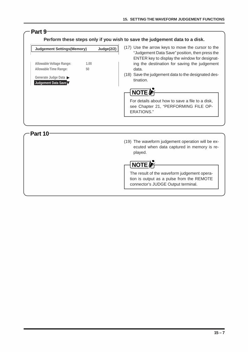
15 – 7
15. SETTING THE WAVEFORM JUDGEMENT FUNCTIONS
Part 9Perform these steps only if you wish to save the judgement data to a disk.
(17) Use the arrow keys to move the cursor to the“Judgement Data Save” position, then press theENTER key to display the window for designat-ing the destination for saving the judgementdata.
(18) Save the judgement data to the designated des-tination.
NOTEFor details about how to save a file to a disk,see Chapter 21, “PERFORMING FILE OP-ERATIONS.”
Part 10(19) The waveform judgement operation will be ex-
ecuted when data captured in memory is re-played.
NOTEThe result of the waveform judgement opera-tion is output as a pulse from the REMOTEconnector’s JUDGE Output terminal.
Judgement Settings(Memory) Judge(2/2)
Allowable Voltage Range: 1.00Allowable Time Range: 50
Generate Judge DataJudgement Data Save

15 – 8
15. SETTING THE WAVEFORM JUDGEMENT FUNCTIONS
16 – 1
16. PERFORMING DISK OPERATIONS
PERFORMING DISK OPERATIONS
This chapter explains the procedural flow of disk opera-tions.
16.1 Saving Your Settings16.2 Loading Your Settings16.3 Displaying Information about a File16.4 Copying a File or Folder16.5 Renaming a File or Folder16.6 Deleting a File or Folder16.7 Reformatting a Hard Disk16.8 Formatting a Disk16.9 Listing the Recorder’s Existing Drives
CHAPTER 16CHAPTER 16
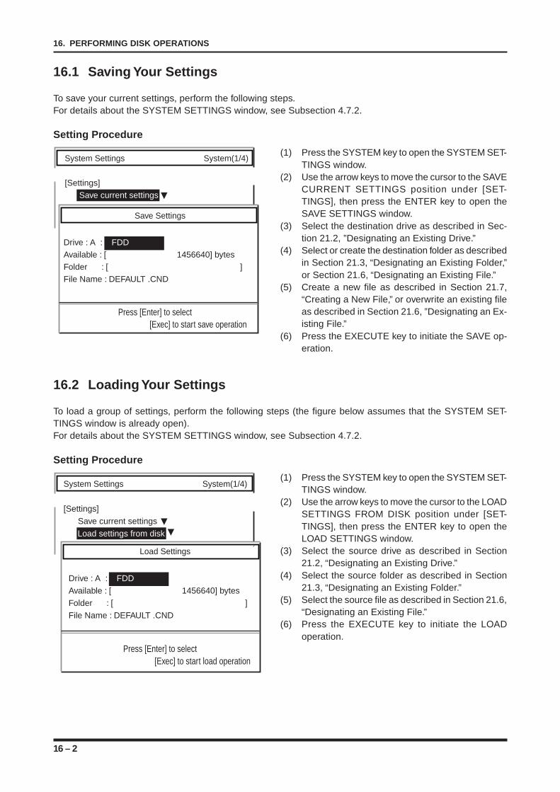
16 – 2
16. PERFORMING DISK OPERATIONS
16.1 Saving Your Settings
To save your current settings, perform the following steps.For details about the SYSTEM SETTINGS window, see Subsection 4.7.2.
Setting Procedure
(1) Press the SYSTEM key to open the SYSTEM SET-TINGS window.
(2) Use the arrow keys to move the cursor to the SAVECURRENT SETTINGS position under [SET-TINGS], then press the ENTER key to open theSAVE SETTINGS window.
(3) Select the destination drive as described in Sec-tion 21.2, ”Designating an Existing Drive.”
(4) Select or create the destination folder as describedin Section 21.3, “Designating an Existing Folder,”or Section 21.6, “Designating an Existing File.”
(5) Create a new file as described in Section 21.7,“Creating a New File,” or overwrite an existing fileas described in Section 21.6, ”Designating an Ex-isting File.”
(6) Press the EXECUTE key to initiate the SAVE op-eration.
16.2 Loading Your Settings
To load a group of settings, perform the following steps (the figure below assumes that the SYSTEM SET-TINGS window is already open).For details about the SYSTEM SETTINGS window, see Subsection 4.7.2.
Setting Procedure
(1) Press the SYSTEM key to open the SYSTEM SET-TINGS window.
(2) Use the arrow keys to move the cursor to the LOADSETTINGS FROM DISK position under [SET-TINGS], then press the ENTER key to open theLOAD SETTINGS window.
(3) Select the source drive as described in Section21.2, “Designating an Existing Drive.”
(4) Select the source folder as described in Section21.3, “Designating an Existing Folder.”
(5) Select the source file as described in Section 21.6,“Designating an Existing File.”
(6) Press the EXECUTE key to initiate the LOADoperation.
System Settings System(1/4)
[Settings]
Save current settings
Save Settings
Drive : A : FDDAvailable : [ 1456640] bytesFolder : [ ]File Name : DEFAULT .CND
Press [Enter] to select[Exec] to start save operation
System Settings System(1/4)
[Settings]
Save current settings
Load settings from disk
Load Settings
Drive : A : FDDAvailable : [ 1456640] bytesFolder : [ ]File Name : DEFAULT .CND
Press [Enter] to select[Exec] to start load operation
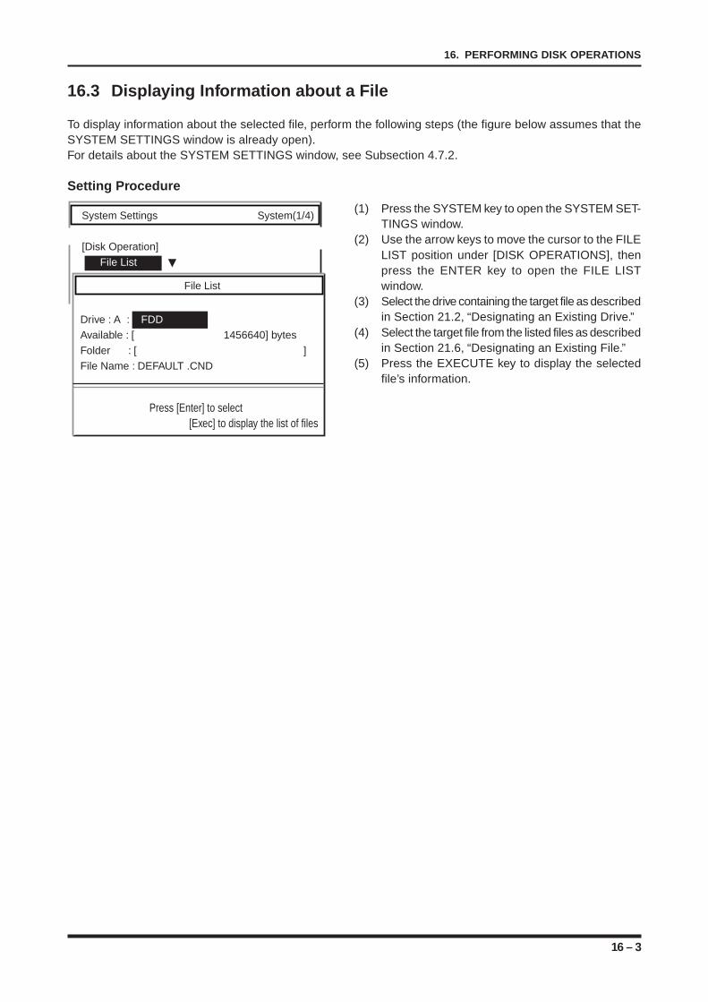
16 – 3
16. PERFORMING DISK OPERATIONS
16.3 Displaying Information about a File
To display information about the selected file, perform the following steps (the figure below assumes that theSYSTEM SETTINGS window is already open).For details about the SYSTEM SETTINGS window, see Subsection 4.7.2.
Setting Procedure
(1) Press the SYSTEM key to open the SYSTEM SET-TINGS window.
(2) Use the arrow keys to move the cursor to the FILELIST position under [DISK OPERATIONS], thenpress the ENTER key to open the FILE LISTwindow.
(3) Select the drive containing the target file as describedin Section 21.2, “Designating an Existing Drive.”
(4) Select the target file from the listed files as describedin Section 21.6, “Designating an Existing File.”
(5) Press the EXECUTE key to display the selectedfile’s information.
System Settings System(1/4)
[Disk Operation]
File List
File List
Drive : A : FDDAvailable : [ 1456640] bytesFolder : [ ]File Name : DEFAULT .CND
Press [Enter] to select[Exec] to display the list of files
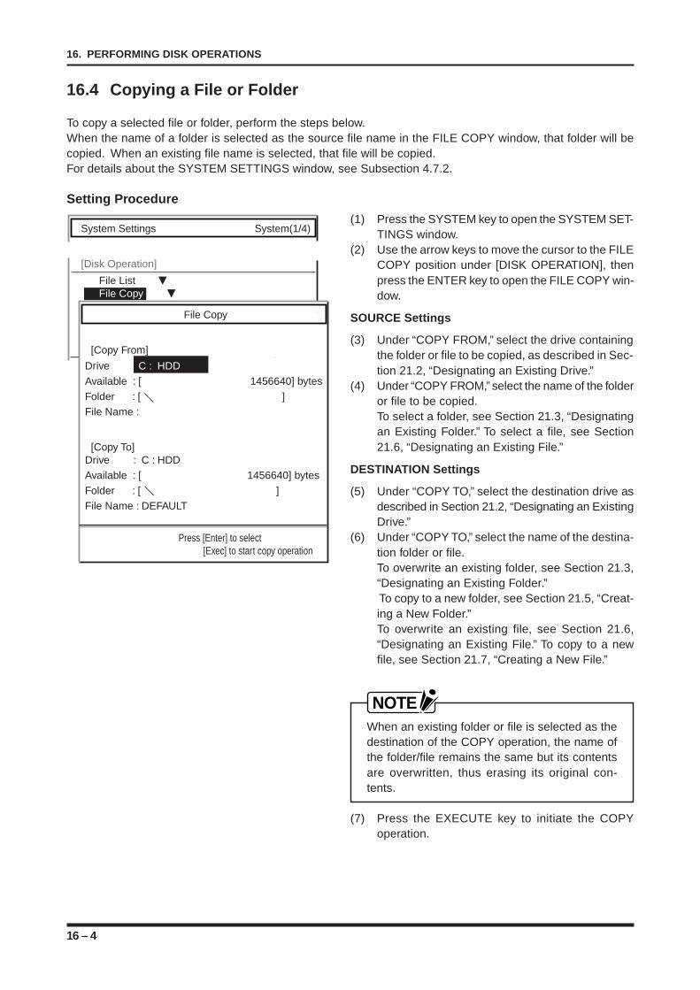
16 – 4
16. PERFORMING DISK OPERATIONS
16.4 Copying a File or Folder
To copy a selected file or folder, perform the steps below.When the name of a folder is selected as the source file name in the FILE COPY window, that folder will becopied. When an existing file name is selected, that file will be copied.For details about the SYSTEM SETTINGS window, see Subsection 4.7.2.
Setting Procedure
(1) Press the SYSTEM key to open the SYSTEM SET-TINGS window.
(2) Use the arrow keys to move the cursor to the FILECOPY position under [DISK OPERATION], thenpress the ENTER key to open the FILE COPY win-dow.
SOURCE Settings
(3) Under “COPY FROM,” select the drive containingthe folder or file to be copied, as described in Sec-tion 21.2, “Designating an Existing Drive.”
(4) Under “COPY FROM,” select the name of the folderor file to be copied.To select a folder, see Section 21.3, “Designatingan Existing Folder.” To select a file, see Section21.6, “Designating an Existing File.”
DESTINATION Settings
(5) Under “COPY TO,” select the destination drive asdescribed in Section 21.2, “Designating an ExistingDrive.”
(6) Under “COPY TO,” select the name of the destina-tion folder or file.To overwrite an existing folder, see Section 21.3,“Designating an Existing Folder.” To copy to a new folder, see Section 21.5, “Creat-ing a New Folder.”To overwrite an existing file, see Section 21.6,“Designating an Existing File.” To copy to a newfile, see Section 21.7, “Creating a New File.”
NOTEWhen an existing folder or file is selected as thedestination of the COPY operation, the name ofthe folder/file remains the same but its contentsare overwritten, thus erasing its original con-tents.
(7) Press the EXECUTE key to initiate the COPYoperation.
System Settings System(1/4)
[Disk Operation]
File List File Copy
File Copy
[Copy From]
Drive : C : HDDAvailable : [ 1456640] bytesFolder : [ ]File Name :
[Copy To]Drive : C : HDDAvailable : [ 1456640] bytesFolder : [ ]File Name : DEFAULT
Press [Enter] to select[Exec] to start copy operation

16 – 5
16. PERFORMING DISK OPERATIONS
16.5 Renaming a File or Folder
To rename a selected file or folder, perform the steps below.For details about the SYSTEM SETTINGS window, see Subsection 4.7.2.
Setting Procedure
(1) Press the SYSTEM key to open the SYSTEM SET-TINGS window.
(2) Use the arrow keys to move the cursor to the FILERENAME position under [DISK OPERATION].
(3) Press the ENTER key to open the FILE RENAMEwindow.
(4) Under “CURRENT,” select the drive containing thefolder or file to be renamed, as described in Section21.2, “Designating an Existing Drive.”
(5) Under “CURRENT,” select the name of the folderor file to be renamed.To select a folder, see Section 21.3, “Designatingan Existing Folder.”To select a file, see Section 21.6, “Designating anExisting File.”
(6) Under “NEW NAME,” select the new name of thefolder or file, using the numeric keypad, arrow keys,or jog/shuttle dial.To create a new folder, see Section 21.5, “Creat-ing a New Folder.To create a new file, see Section 21.7, “Creating aNew File.”
(7) Press the EXECUTE key to initiate the RENAMEoperation.
System Settings System(1/4)
[Disk Operation]
File List File Copy File Rename
File Rename
[Current]
Drive : C : HDDAvailable : [ 1456640] bytesFolder : [ ]File Name :
[New Name]File Name : DEFAULT
Press [Enter] to select[Exec] to change file name
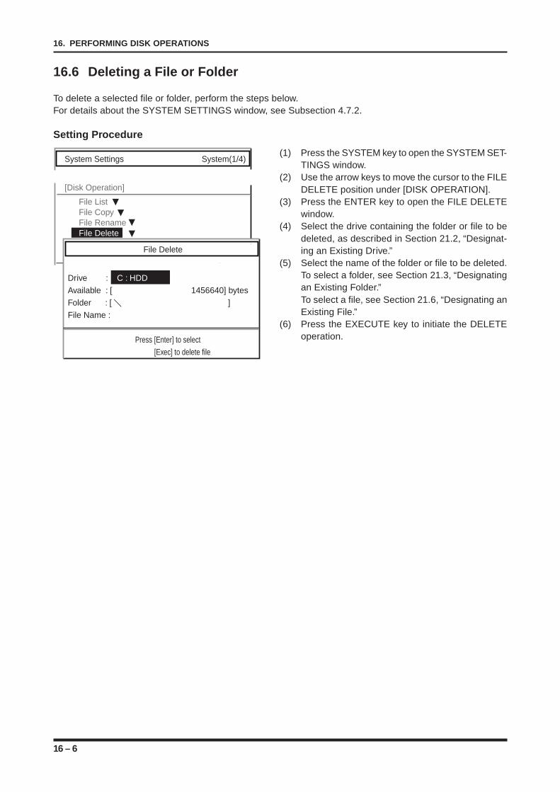
16 – 6
16. PERFORMING DISK OPERATIONS
16.6 Deleting a File or Folder
To delete a selected file or folder, perform the steps below.For details about the SYSTEM SETTINGS window, see Subsection 4.7.2.
Setting Procedure
(1) Press the SYSTEM key to open the SYSTEM SET-TINGS window.
(2) Use the arrow keys to move the cursor to the FILEDELETE position under [DISK OPERATION].
(3) Press the ENTER key to open the FILE DELETEwindow.
(4) Select the drive containing the folder or file to bedeleted, as described in Section 21.2, “Designat-ing an Existing Drive.”
(5) Select the name of the folder or file to be deleted.To select a folder, see Section 21.3, “Designatingan Existing Folder.”To select a file, see Section 21.6, “Designating anExisting File.”
(6) Press the EXECUTE key to initiate the DELETEoperation.
System Settings System(1/4)
[Disk Operation]
File List File Copy File Rename File Delete
File Delete
Drive : C : HDDAvailable : [ 1456640] bytesFolder : [ ]File Name :
Press [Enter] to select[Exec] to delete file
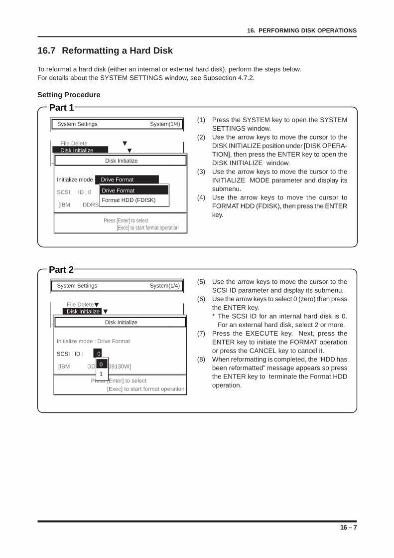
16 – 7
16. PERFORMING DISK OPERATIONS
Part 2
16.7 Reformatting a Hard Disk
To reformat a hard disk (either an internal or external hard disk), perform the steps below.For details about the SYSTEM SETTINGS window, see Subsection 4.7.2.
Setting Procedure
Part 1(1) Press the SYSTEM key to open the SYSTEM
SETTINGS window.(2) Use the arrow keys to move the cursor to the
DISK INITIALIZE position under [DISK OPERA-TION], then press the ENTER key to open theDISK INITIALIZE window.
(3) Use the arrow keys to move the cursor to theINITIALIZE MODE parameter and display itssubmenu.
(4) Use the arrow keys to move the cursor toFORMAT HDD (FDISK), then press the ENTERkey.
(5) Use the arrow keys to move the cursor to theSCSI ID parameter and display its submenu.
(6) Use the arrow keys to select 0 (zero) then pressthe ENTER key.* The SCSI ID for an internal hard disk is 0.
For an external hard disk, select 2 or more.(7) Press the EXECUTE key. Next, press the
ENTER key to initiate the FORMAT operationor press the CANCEL key to cancel it.
(8) When reformatting is completed, the “HDD hasbeen reformatted” message appears so pressthe ENTER key to terminate the Format HDDoperation.
System Settings System(1/4)
File Delete Disk Initialize
Disk Initialize
Initialize mode Drive Format
SCSI ID : 0
[IBM DDRS
Press [Enter] to select[Exec] to start format operation
Drive Format
Format HDD (FDISK)
System Settings System(1/4)
File DeleteDisk Initialize
Disk Initialize
Initialize mode : Drive Format
SCSI ID : 0
[IBM DDRS - 39130W]
Press [Enter] to select[Exec] to start format operation
0
1
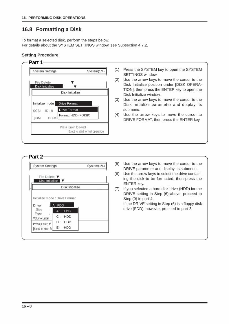
16 – 8
16. PERFORMING DISK OPERATIONS
Part 1
Part 2
16.8 Formatting a Disk
To format a selected disk, perform the steps below.For details about the SYSTEM SETTINGS window, see Subsection 4.7.2.
Setting Procedure
(1) Press the SYSTEM key to open the SYSTEMSETTINGS window.
(2) Use the arrow keys to move the cursor to theDisk Initialize position under [DISK OPERA-TION], then press the ENTER key to open theDisk Initialize window.
(3) Use the arrow keys to move the cursor to theDisk Initialize parameter and display itssubmenu.
(4) Use the arrow keys to move the cursor toDRIVE FORMAT, then press the ENTER key.
(5) Use the arrow keys to move the cursor to theDRIVE parameter and display its submenu.
(6) Use the arrow keys to select the drive contain-ing the disk to be formatted, then press theENTER key.
(7) If you selected a hard disk drive (HDD) for theDRIVE setting in Step (6) above, proceed toStep (9) in part 4.If the DRIVE setting in Step (6) is a floppy diskdrive (FDD), however, proceed to part 3.
System Settings System(1/4)
File DeleteDisk Initialize
Disk Initialize
Initialize mode : Drive Format
Drive : A : FDD Size : Type :Volume Label :
Press [Enter] to select[Exec] to start format operation
A : FDD
C : HDD
D : HDD
E : HDD
System Settings System(1/4)
File Delete Disk Initialize
Disk Initialize
Initialize mode Drive Format
SCSI ID : 0
[IBM DDRS
Press [Enter] to select[Exec] to start format operation
Drive Format
Format HDD (FDISK)
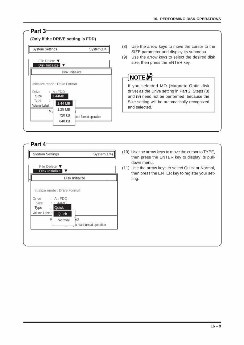
16 – 9
16. PERFORMING DISK OPERATIONS
Part 3
Part 4
(Only if the DRIVE setting is FDD)
(8) Use the arrow keys to move the cursor to theSIZE parameter and display its submenu.
(9) Use the arrow keys to select the desired disksize, then press the ENTER key.
NOTEIf you selected MO (Magneto-Optic diskdrive) as the Drive setting in Part 2, Steps (8)and (9) need not be performed because theSize setting will be automatically recognizedand selected.
(10) Use the arrow keys to move the cursor to TYPE,then press the ENTER key to display its pull-down menu.
(11) Use the arrow keys to select Quick or Normal,then press the ENTER key to register your set-ting.
System Settings System(1/4)
File DeleteDisk Initialize
Disk Initialize
Initialize mode : Drive Format
Drive : A : FDD Size : 1.44MB Type :Volume Label :
Press [Enter] to select[Exec] to start format operation
1.44 MB
1.25 MB
720 kB
640 kB
System Settings System(1/4)
File DeleteDisk Initialize
Disk Initialize
Initialize mode : Drive Format
Drive : A : FDD Size : 1.44MB Type : QuickVolume Label :
Press [Enter] to select[Exec] to start format operation
Quick
Normal
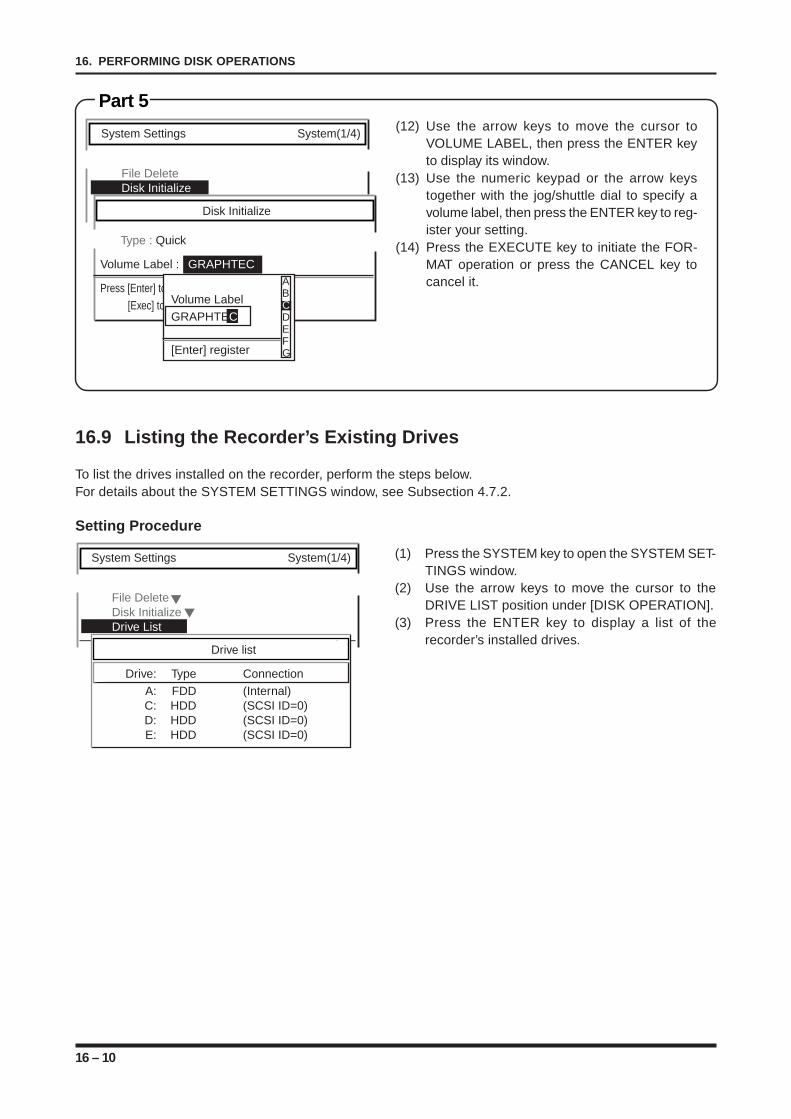
16 – 10
16. PERFORMING DISK OPERATIONS
System Settings System(1/4)
File Delete Disk Initialize
Disk Initialize
Type : Quick
Volume Label : GRAPHTEC
Press [Enter] to select[Exec] to start format operationVolume Label
GRAPHTEC
[Enter] register
ABCDEFG
Part 5(12) Use the arrow keys to move the cursor to
VOLUME LABEL, then press the ENTER keyto display its window.
(13) Use the numeric keypad or the arrow keystogether with the jog/shuttle dial to specify avolume label, then press the ENTER key to reg-ister your setting.
(14) Press the EXECUTE key to initiate the FOR-MAT operation or press the CANCEL key tocancel it.
16.9 Listing the Recorder’s Existing Drives
To list the drives installed on the recorder, perform the steps below.For details about the SYSTEM SETTINGS window, see Subsection 4.7.2.
Setting Procedure
(1) Press the SYSTEM key to open the SYSTEM SET-TINGS window.
(2) Use the arrow keys to move the cursor to theDRIVE LIST position under [DISK OPERATION].
(3) Press the ENTER key to display a list of therecorder’s installed drives.
System Settings System(1/4)
File Delete Disk InitializeDrive List
Drive list
Drive: Type ConnectionA: FDD (Internal)C: HDD (SCSI ID=0)D: HDD (SCSI ID=0)E: HDD (SCSI ID=0)
17 – 1
17. SETTING THE INTERFACE FUNCTIONS
CHAPTER 17CHAPTER 17SETTING THE INTERFACE FUNCTIONS
This chapter describes how to set the interface functions.
17.1 Selecting the Interface Type17.2 Selecting the New Line Code17.3 Setting the RS-232C Interface Conditions17.3.1 Selecting the Transfer Speed17.3.2 Selecting the Length of the DATA Byte17.3.3 Selecting the Number of Stop Bit(s)17.3.4 Selecting the Parity Mode17.3.5 Selecting the Handshaking (Flow Control) Mode17.3.6 Selecting the Time Out Interval17.4 Setting the GP-IB Interface Conditions17.4.1 Selecting the Recorder’s Device Address17.4.2 Selecting the Terminator Code17.4.3 Selecting the Time Out Interval
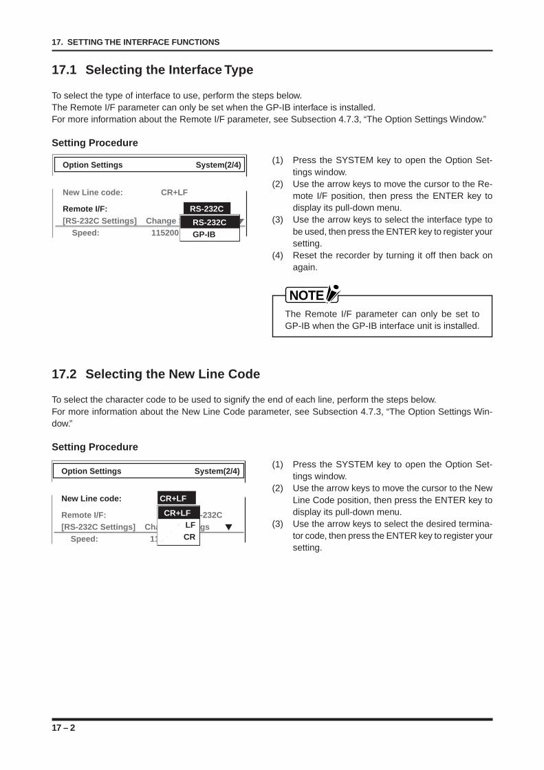
17 – 2
17. SETTING THE INTERFACE FUNCTIONS
17.1 Selecting the Interface Type
To select the type of interface to use, perform the steps below.The Remote I/F parameter can only be set when the GP-IB interface is installed.For more information about the Remote I/F parameter, see Subsection 4.7.3, “The Option Settings Window.”
Setting Procedure
(1) Press the SYSTEM key to open the Option Set-tings window.
(2) Use the arrow keys to move the cursor to the Re-mote I/F position, then press the ENTER key todisplay its pull-down menu.
(3) Use the arrow keys to select the interface type tobe used, then press the ENTER key to register yoursetting.
(4) Reset the recorder by turning it off then back onagain.
NOTEThe Remote I/F parameter can only be set toGP-IB when the GP-IB interface unit is installed.
17.2 Selecting the New Line Code
To select the character code to be used to signify the end of each line, perform the steps below.For more information about the New Line Code parameter, see Subsection 4.7.3, “The Option Settings Win-dow.”
Setting Procedure
(1) Press the SYSTEM key to open the Option Set-tings window.
(2) Use the arrow keys to move the cursor to the NewLine Code position, then press the ENTER key todisplay its pull-down menu.
(3) Use the arrow keys to select the desired termina-tor code, then press the ENTER key to register yoursetting.
Option Settings System(2/4)
New Line code: CR+LF
Remote I/F: RS-232C[RS-232C Settings] Change Settings
Speed: 115200 bpsRS-232CGP-IB
Option Settings System(2/4)
New Line code: CR+LF
Remote I/F: RS-232C[RS-232C Settings] Change Settings
Speed: 115200 bps
CR+LFLFCR
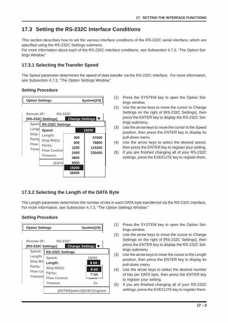
17 – 3
17. SETTING THE INTERFACE FUNCTIONS
17.3 Setting the RS-232C Interface Conditions
This section describes how to set the various interface conditions of the RS-232C serial interface, which arespecified using the RS-232C Settings submenu.For more information about each of the RS-232C interface conditions, see Subsection 4.7.3, “The Option Set-tings Window.”
17.3.1 Selecting the Transfer Speed
The Speed parameter determines the speed of data transfer via the RS-232C interface. For more information,see Subsection 4.7.3, “The Option Settings Window.”
Setting Procedure
(1) Press the SYSTEM key to open the Option Set-tings window.
(2) Use the arrow keys to move the cursor to ChangeSettings on the right of [RS-232C Settings], thenpress the ENTER key to display the RS-232C Set-tings submenu.
(3) Use the arrow keys to move the cursor to the Speedposition, then press the ENTER key to display itspull-down menu.
(4) Use the arrow keys to select the desired speed,then press the ENTER key to register your setting.
(5) If you are finished changing all of your RS-232Csettings, press the EXECUTE key to register them.
17.3.2 Selecting the Length of the DATA Byte
The Length parameter determines the number of bits in each DATA byte transferred via the RS-232C interface.For more information, see Subsection 4.7.3, “The Option Settings Window.”
Setting Procedure
(1) Press the SYSTEM key to open the Option Set-tings window.
(2) Use the arrow keys to move the cursor to ChangeSettings on the right of [RS-232C Settings], thenpress the ENTER key to display the RS-232C Set-tings submenu.
(3) Use the arrow keys to move the cursor to the Lengthposition, then press the ENTER key to display itspull-down menu.
(4) Use the arrow keys to select the desired numberof bits per DATA byte, then press the ENTER keyto register your setting.
(5) If you are finished changing all of your RS-232Csettings, press the EXECUTE key to register them.
Option Settings System(2/4)
Remote I/F: RS-232C[RS-232C Settings] Change Settings
Speed: 115200 bpsLength: 8 bitStop Bit: 1 bitParity: NoneFlow Control: RS-CSTimeout: 2s
RS-232C Settings
Speed: 19200Length: 8 bitStop Bit(s): 1 bitParity: NoneFlow Control: NoneTimeout: 2s
[ENTER]select/[EXEC]register
300 57600600 76800
1200 1152002400 23040048009600
1920038400
Option Settings System(2/4)
Remote I/F: RS-232C[RS-232C Settings] Change Settings
Speed: 115200 bpsLength: 8 bitStop Bit: 1 bitParity: NoneFlow Control: RS-CSTimeout: 2s
RS-232C Settings
Speed: 19200Length: 8 bitStop Bit(s): 1 bitParity: NoneFlow Control: NoneTimeout: 2s
[ENTER]select/[EXEC]register
8 bit7 bit
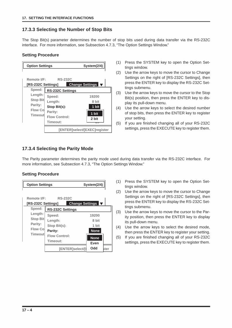
17 – 4
17. SETTING THE INTERFACE FUNCTIONS
17.3.3 Selecting the Number of Stop Bits
The Stop Bit(s) parameter determines the number of stop bits used during data transfer via the RS-232Cinterface. For more information, see Subsection 4.7.3, “The Option Settings Window.”
Setting Procedure
(1) Press the SYSTEM key to open the Option Set-tings window.
(2) Use the arrow keys to move the cursor to ChangeSettings on the right of [RS-232C Settings], thenpress the ENTER key to display the RS-232C Set-tings submenu.
(3) Use the arrow keys to move the cursor to the StopBit(s) position, then press the ENTER key to dis-play its pull-down menu.
(4) Use the arrow keys to select the desired numberof stop bits, then press the ENTER key to registeryour setting.
(5) If you are finished changing all of your RS-232Csettings, press the EXECUTE key to register them.
17.3.4 Selecting the Parity Mode
The Parity parameter determines the parity mode used during data transfer via the RS-232C interface. Formore information, see Subsection 4.7.3, “The Option Settings Window.”
Setting Procedure
(1) Press the SYSTEM key to open the Option Set-tings window.
(2) Use the arrow keys to move the cursor to ChangeSettings on the right of [RS-232C Settings], thenpress the ENTER key to display the RS-232C Set-tings submenu.
(3) Use the arrow keys to move the cursor to the Par-ity position, then press the ENTER key to displayits pull-down menu.
(4) Use the arrow keys to select the desired mode,then press the ENTER key to register your setting.
(5) If you are finished changing all of your RS-232Csettings, press the EXECUTE key to register them.
Option Settings System(2/4)
Remote I/F: RS-232C[RS-232C Settings] Change Settings
Speed: 115200 bpsLength: 8 bitStop Bit: 1 bitParity: NoneFlow Control: RS-CSTimeout: 2s
RS-232C Settings
Speed: 19200Length: 8 bitStop Bit(s): 1 bitParity: NoneFlow Control: NoneTimeout: 2s
[ENTER]select/[EXEC]register
1 bit2 bit
Option Settings System(2/4)
Remote I/F: RS-232C[RS-232C Settings] Change Settings
Speed: 115200 bpsLength: 8 bitStop Bit: 1 bitParity: NoneFlow Control: RS-CSTimeout: 2s
RS-232C Settings
Speed: 19200Length: 8 bitStop Bit(s): 1 bitParity: NoneFlow Control: NoneTimeout: 2s
[ENTER]select/[EXEC]register
NoneEvenOdd
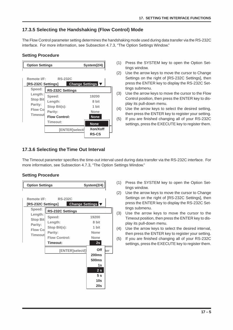
17 – 5
17. SETTING THE INTERFACE FUNCTIONS
17.3.5 Selecting the Handshaking (Flow Control) Mode
The Flow Control parameter setting determines the handshaking mode used during data transfer via the RS-232Cinterface. For more information, see Subsection 4.7.3, “The Option Settings Window.”
Setting Procedure
(1) Press the SYSTEM key to open the Option Set-tings window.
(2) Use the arrow keys to move the cursor to ChangeSettings on the right of [RS-232C Settings], thenpress the ENTER key to display the RS-232C Set-tings submenu.
(3) Use the arrow keys to move the cursor to the FlowControl position, then press the ENTER key to dis-play its pull-down menu.
(4) Use the arrow keys to select the desired setting,then press the ENTER key to register your setting.
(5) If you are finished changing all of your RS-232Csettings, press the EXECUTE key to register them.
17.3.6 Selecting the Time Out Interval
The Timeout parameter specifies the time-out interval used during data transfer via the RS-232C interface. Formore information, see Subsection 4.7.3, “The Option Settings Window.”
Setting Procedure
(1) Press the SYSTEM key to open the Option Set-tings window.
(2) Use the arrow keys to move the cursor to ChangeSettings on the right of [RS-232C Settings], thenpress the ENTER key to display the RS-232C Set-tings submenu.
(3) Use the arrow keys to move the cursor to theTimeout position, then press the ENTER key to dis-play its pull-down menu.
(4) Use the arrow keys to select the desired interval,then press the ENTER key to register your setting.
(5) If you are finished changing all of your RS-232Csettings, press the EXECUTE key to register them.
Option Settings System(2/4)
Remote I/F: RS-232C[RS-232C Settings] Change Settings
Speed: 115200 bpsLength: 8 bitStop Bit: 1 bitParity: NoneFlow Control: RS-CSTimeout: 2s
RS-232C Settings
Speed: 19200Length: 8 bitStop Bit(s): 1 bitParity: NoneFlow Control: NoneTimeout: 2s
[ENTER]select/[EXEC]register
NoneXon/XoffRS-CS
Option Settings System(2/4)
Remote I/F: RS-232C[RS-232C Settings] Change Settings
Speed: 115200 bpsLength: 8 bitStop Bit: 1 bitParity: NoneFlow Control: RS-CSTimeout: 2s
RS-232C Settings
Speed: 19200Length: 8 bitStop Bit(s): 1 bitParity: NoneFlow Control: NoneTimeout: 2s
[ENTER]select/[EXEC]registerOff200ms500ms
1s2 s5 s
10s20s
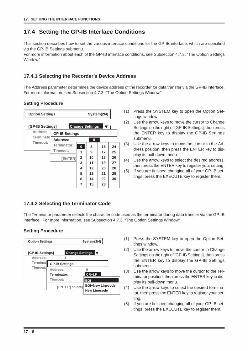
17 – 6
17. SETTING THE INTERFACE FUNCTIONS
17.4 Setting the GP-IB Interface Conditions
This section describes how to set the various interface conditions for the GP-IB interface, which are specifiedvia the GP-IB Settings submenu.For more information about each of the GP-IB interface conditions, see Subsection 4.7.3, “The Option SettingsWindow.”
17.4.1 Selecting the Recorder’s Device Address
The Address parameter determines the device address of the recorder for data transfer via the GP-IB interface.For more information, see Subsection 4.7.3, “The Option Settings Window.”
Setting Procedure
(1) Press the SYSTEM key to open the Option Set-tings window.
(2) Use the arrow keys to move the cursor to ChangeSettings on the right of [GP-IB Settings], then pressthe ENTER key to display the GP-IB Settingssubmenu.
(3) Use the arrow keys to move the cursor to the Ad-dress position, then press the ENTER key to dis-play its pull-down menu.
(4) Use the arrow keys to select the desired address,then press the ENTER key to register your setting.
(5) If you are finished changing all of your GP-IB set-tings, press the EXECUTE key to register them.
17.4.2 Selecting the Terminator Code
The Terminator parameter selects the character code used as the terminator during data transfer via the GP-IBinterface. For more information, see Subsection 4.7.3, “The Option Settings Window.”
Setting Procedure
(1) Press the SYSTEM key to open the Option Set-tings window.
(2) Use the arrow keys to move the cursor to ChangeSettings on the right of [GP-IB Settings], then pressthe ENTER key to display the GP-IB Settingssubmenu.
(3) Use the arrow keys to move the cursor to the Ter-minator position, then press the ENTER key to dis-play its pull-down menu.
(4) Use the arrow keys to select the desired termina-tor, then press the ENTER key to register your set-ting.
(5) If you are finished changing all of your GP-IB set-tings, press the EXECUTE key to register them.
Option Settings System(2/4)
[GP-IB Settings] Change SettingsAddress: 1Terminator: CR+LFTimeout: 200ms
GP-IB Settings
Address: 0Terminator: CR+LFTimeout: 2 S
[ENTER] select/[EXEC] register
0 8 16 241 9 17 252 10 18 263 11 19 274 12 20 285 13 21 296 14 22 307 15 23
Option Settings System(2/4)
[GP-IB Settings] Change SettingsAddress: 1Terminator: CR+LFTimeout: 200ms
GP-IB Settings
Address: 0Terminator: CR+LFTimeout: 2 S
[ENTER] select/[EXEC] register
EOI LFEOI+New LinecodeNew Linecode
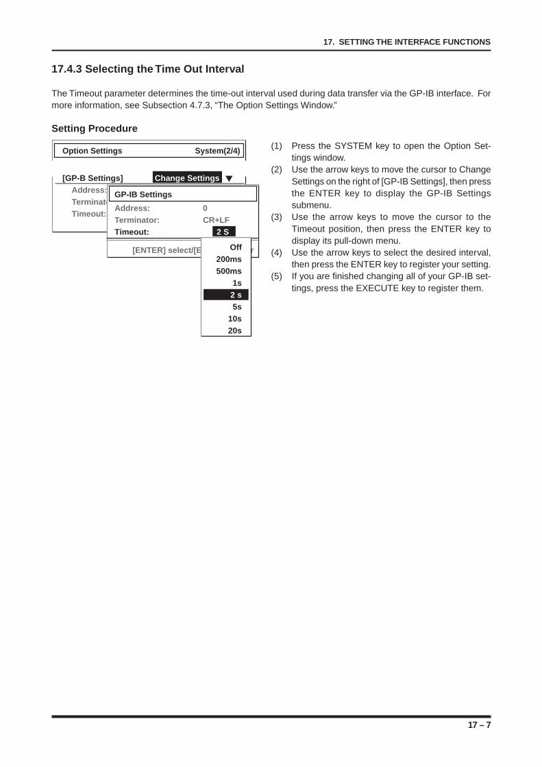
17 – 7
17. SETTING THE INTERFACE FUNCTIONS
17.4.3 Selecting the Time Out Interval
The Timeout parameter determines the time-out interval used during data transfer via the GP-IB interface. Formore information, see Subsection 4.7.3, “The Option Settings Window.”
Setting Procedure
(1) Press the SYSTEM key to open the Option Set-tings window.
(2) Use the arrow keys to move the cursor to ChangeSettings on the right of [GP-IB Settings], then pressthe ENTER key to display the GP-IB Settingssubmenu.
(3) Use the arrow keys to move the cursor to theTimeout position, then press the ENTER key todisplay its pull-down menu.
(4) Use the arrow keys to select the desired interval,then press the ENTER key to register your setting.
(5) If you are finished changing all of your GP-IB set-tings, press the EXECUTE key to register them.
Option Settings System(2/4)
[GP-B Settings] Change SettingsAddress: 1Terminator: CR+LFTimeout: 200ms
GP-IB Settings
Address: 0Terminator: CR+LFTimeout: 2 S
[ENTER] select/[EXEC] registerOff200ms500ms
1s2 s5s
10s20s

17 – 8
17. SETTING THE INTERFACE FUNCTIONS
18 – 1
18. USING THE BASIC FUNCTIONS
CHAPTER 18CHAPTER 18USING THE BASIC FUNCTIONS
This chapter describes how to use the recorder’s basicfunctions.
18.1 Locking the Panel Keys18.2 Returning the Settings to Their Factory Default
Settings18.3 Adjusting the Backlit Display’s Brightness18.4 Using the Screen Saver18.5 Starting Measurement/Printing When the Power is
Turned On18.6 Using the Beeper and Adjusting Its Volume18.7 Enabling the Key Click Sound18.8 Changing the Date and Time18.9 Changing the Displayed Language18.10 Using the Long-Length Z-Fold Unit18.11 Making a Copy of the Screen Display
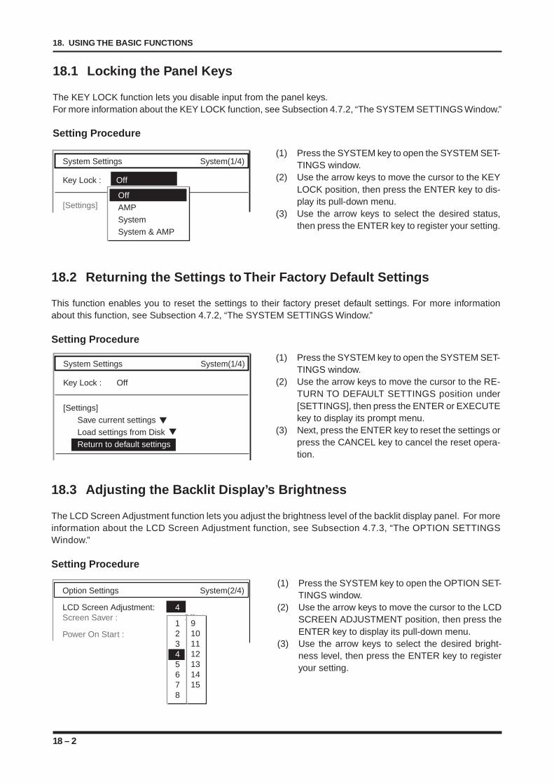
18 – 2
18. USING THE BASIC FUNCTIONS
18.1 Locking the Panel Keys
The KEY LOCK function lets you disable input from the panel keys.For more information about the KEY LOCK function, see Subsection 4.7.2, “The SYSTEM SETTINGS Window.”
Setting Procedure
(1) Press the SYSTEM key to open the SYSTEM SET-TINGS window.
(2) Use the arrow keys to move the cursor to the KEYLOCK position, then press the ENTER key to dis-play its pull-down menu.
(3) Use the arrow keys to select the desired status,then press the ENTER key to register your setting.
18.2 Returning the Settings to Their Factory Default Settings
This function enables you to reset the settings to their factory preset default settings. For more informationabout this function, see Subsection 4.7.2, “The SYSTEM SETTINGS Window.”
Setting Procedure
(1) Press the SYSTEM key to open the SYSTEM SET-TINGS window.
(2) Use the arrow keys to move the cursor to the RE-TURN TO DEFAULT SETTINGS position under[SETTINGS], then press the ENTER or EXECUTEkey to display its prompt menu.
(3) Next, press the ENTER key to reset the settings orpress the CANCEL key to cancel the reset opera-tion.
18.3 Adjusting the Backlit Display’s Brightness
The LCD Screen Adjustment function lets you adjust the brightness level of the backlit display panel. For moreinformation about the LCD Screen Adjustment function, see Subsection 4.7.3, “The OPTION SETTINGSWindow.”
Setting Procedure
(1) Press the SYSTEM key to open the OPTION SET-TINGS window.
(2) Use the arrow keys to move the cursor to the LCDSCREEN ADJUSTMENT position, then press theENTER key to display its pull-down menu.
(3) Use the arrow keys to select the desired bright-ness level, then press the ENTER key to registeryour setting.
System Settings System(1/4)
Key Lock : Off
[Settings]Off
AMP
System
System & AMP
Option Settings System(2/4)
LCD Screen Adjustment: 4Screen Saver : Off
Power On Start : On12345678
9101112131415
System Settings System(1/4)
Key Lock : Off
[Settings]
Save current settings
Load settings from Disk
Return to default settings
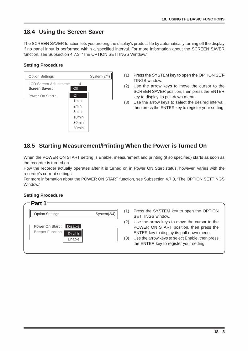
18 – 3
18. USING THE BASIC FUNCTIONS
18.4 Using the Screen Saver
The SCREEN SAVER function lets you prolong the display’s product life by automatically turning off the displayif no panel input is performed within a specified interval. For more information about the SCREEN SAVERfunction, see Subsection 4.7.3, “The OPTION SETTINGS Window.”
Setting Procedure
(1) Press the SYSTEM key to open the OPTION SET-TINGS window.
(2) Use the arrow keys to move the cursor to theSCREEN SAVER position, then press the ENTERkey to display its pull-down menu.
(3) Use the arrow keys to select the desired interval,then press the ENTER key to register your setting.
18.5 Starting Measurement/Printing When the Power is Turned On
When the POWER ON START setting is Enable, measurement and printing (if so specified) starts as soon asthe recorder is turned on.How the recorder actually operates after it is turned on in Power ON Start status, however, varies with therecorder’s current settings.For more information about the POWER ON START function, see Subsection 4.7.3, “The OPTION SETTINGSWindow.”
Setting Procedure
Part 1(1) Press the SYSTEM key to open the OPTION
SETTINGS window.(2) Use the arrow keys to move the cursor to the
POWER ON START position, then press theENTER key to display its pull-down menu.
(3) Use the arrow keys to select Enable, then pressthe ENTER key to register your setting.
Option Settings System(2/4)
LCD Screen Adjustment: 4Screen Saver : Off
Power On Start : OnOff1min2min5min10min30min60min
Option Settings System(2/4)
Power On Start : Disable Off
Beeper Function : KeyDisable
Enable
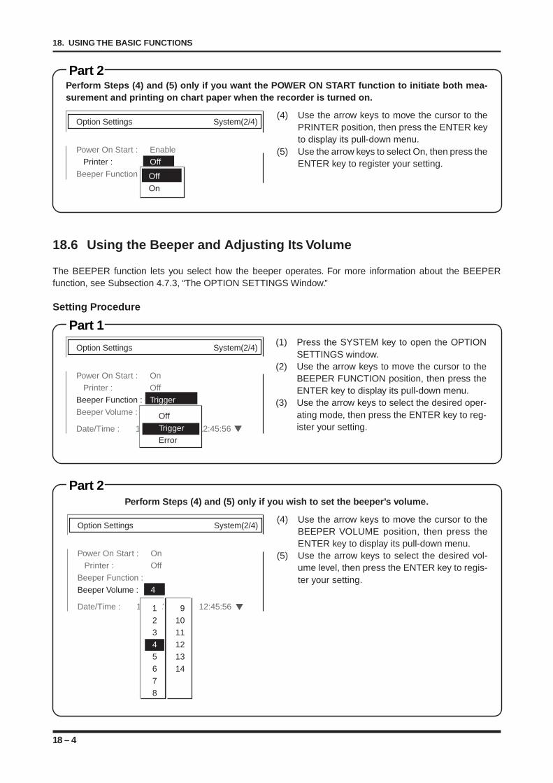
18 – 4
18. USING THE BASIC FUNCTIONS
Part 1
Part 2
18.6 Using the Beeper and Adjusting Its Volume
The BEEPER function lets you select how the beeper operates. For more information about the BEEPERfunction, see Subsection 4.7.3, “The OPTION SETTINGS Window.”
Setting Procedure
(1) Press the SYSTEM key to open the OPTIONSETTINGS window.
(2) Use the arrow keys to move the cursor to theBEEPER FUNCTION position, then press theENTER key to display its pull-down menu.
(3) Use the arrow keys to select the desired oper-ating mode, then press the ENTER key to reg-ister your setting.
Perform Steps (4) and (5) only if you wish to set the beeper’s volume.
(4) Use the arrow keys to move the cursor to theBEEPER VOLUME position, then press theENTER key to display its pull-down menu.
(5) Use the arrow keys to select the desired vol-ume level, then press the ENTER key to regis-ter your setting.
Part 2Perform Steps (4) and (5) only if you want the POWER ON START function to initiate both mea-surement and printing on chart paper when the recorder is turned on.
(4) Use the arrow keys to move the cursor to thePRINTER position, then press the ENTER keyto display its pull-down menu.
(5) Use the arrow keys to select On, then press theENTER key to register your setting.
Option Settings System(2/4)
Power On Start : Enable
Printer : Off
Beeper Function : Off
On
Option Settings System(2/4)
Power On Start : On
Printer : Off
Beeper Function : Trigger
Beeper Volume : 4
Date/Time : 1999/12/31 12:45:56
OffTriggerError
Option Settings System(2/4)
Power On Start : On
Printer : Off
Beeper Function : Key
Beeper Volume : 4
Date/Time : 1999/12/31 12:45:5612345678
91011121314
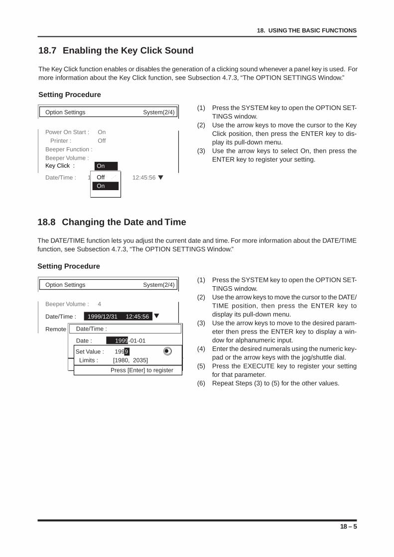
18 – 5
18. USING THE BASIC FUNCTIONS
18.8 Changing the Date and Time
The DATE/TIME function lets you adjust the current date and time. For more information about the DATE/TIMEfunction, see Subsection 4.7.3, “The OPTION SETTINGS Window.”
Setting Procedure
(1) Press the SYSTEM key to open the OPTION SET-TINGS window.
(2) Use the arrow keys to move the cursor to the DATE/TIME position, then press the ENTER key todisplay its pull-down menu.
(3) Use the arrow keys to move to the desired param-eter then press the ENTER key to display a win-dow for alphanumeric input.
(4) Enter the desired numerals using the numeric key-pad or the arrow keys with the jog/shuttle dial.
(5) Press the EXECUTE key to register your settingfor that parameter.
(6) Repeat Steps (3) to (5) for the other values.
18.7 Enabling the Key Click Sound
The Key Click function enables or disables the generation of a clicking sound whenever a panel key is used. Formore information about the Key Click function, see Subsection 4.7.3, “The OPTION SETTINGS Window.”
Setting Procedure
(1) Press the SYSTEM key to open the OPTION SET-TINGS window.
(2) Use the arrow keys to move the cursor to the KeyClick position, then press the ENTER key to dis-play its pull-down menu.
(3) Use the arrow keys to select On, then press theENTER key to register your setting.
Option Settings System(2/4)
Beeper Volume : 4
Date/Time : 1999/12/31 12:45:56
Remote I/F Date/Time :
Date : 1999-01-01
Set Value : 1999Limits : [1980, 2035]
Press [Enter] to register
Option Settings System(2/4)
Power On Start : On
Printer : Off
Beeper Function : Trigger
Beeper Volume : 4Key Click :
Date/Time : 1999/12/31 12:45:56
On
OffOn
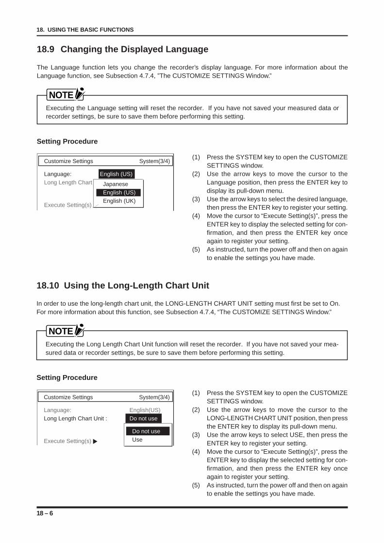
18 – 6
18. USING THE BASIC FUNCTIONS
18.10 Using the Long-Length Chart Unit
In order to use the long-length chart unit, the LONG-LENGTH CHART UNIT setting must first be set to On.For more information about this function, see Subsection 4.7.4, “The CUSTOMIZE SETTINGS Window.”
NOTEExecuting the Long Length Chart Unit function will reset the recorder. If you have not saved your mea-sured data or recorder settings, be sure to save them before performing this setting.
Setting Procedure
(1) Press the SYSTEM key to open the CUSTOMIZESETTINGS window.
(2) Use the arrow keys to move the cursor to theLONG-LENGTH CHART UNIT position, then pressthe ENTER key to display its pull-down menu.
(3) Use the arrow keys to select USE, then press theENTER key to register your setting.
(4) Move the cursor to “Execute Setting(s)”, press theENTER key to display the selected setting for con-firmation, and then press the ENTER key onceagain to register your setting.
(5) As instructed, turn the power off and then on againto enable the settings you have made.
Customize Settings System(3/4)
Language: English(US)Long Length Chart Unit : Do not use
Execute Setting(s)
Do not useUse
18.9 Changing the Displayed Language
The Language function lets you change the recorder’s display language. For more information about theLanguage function, see Subsection 4.7.4, ”The CUSTOMIZE SETTINGS Window.”
NOTEExecuting the Language setting will reset the recorder. If you have not saved your measured data orrecorder settings, be sure to save them before performing this setting.
Setting Procedure
Customize Settings System(3/4)
Language: English (US)Long Length Chart Unit
Execute Setting(s)
JapaneseEnglish (US)English (UK)
(1) Press the SYSTEM key to open the CUSTOMIZESETTINGS window.
(2) Use the arrow keys to move the cursor to theLanguage position, then press the ENTER key todisplay its pull-down menu.
(3) Use the arrow keys to select the desired language,then press the ENTER key to register your setting.
(4) Move the cursor to “Execute Setting(s)”, press theENTER key to display the selected setting for con-firmation, and then press the ENTER key onceagain to register your setting.
(5) As instructed, turn the power off and then on againto enable the settings you have made.
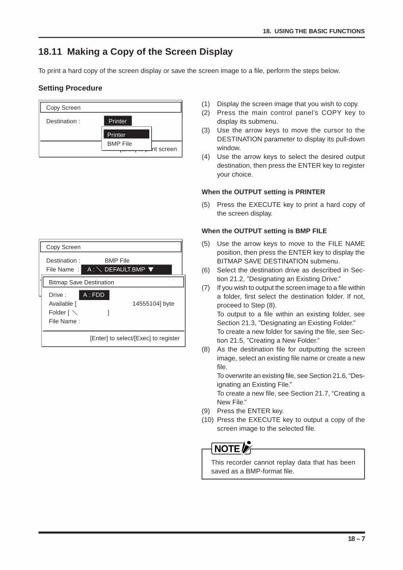
18 – 7
18. USING THE BASIC FUNCTIONS
18.11 Making a Copy of the Screen Display
To print a hard copy of the screen display or save the screen image to a file, perform the steps below.
Setting Procedure
Copy Screen
Destination : Printer
[Exec] to print screen
PrinterBMP File
Copy Screen
Destination : BMP FileFile Name : A : DEFAULT.BMP
Bitmap Save Destination
Drive : A : FDDAvailable [ 14555104] byteFolder [ ]File Name :
[Enter] to select/[Exec] to register
(1) Display the screen image that you wish to copy.(2) Press the main control panel’s COPY key to
display its submenu.(3) Use the arrow keys to move the cursor to the
DESTINATION parameter to display its pull-downwindow.
(4) Use the arrow keys to select the desired outputdestination, then press the ENTER key to registeryour choice.
When the OUTPUT setting is PRINTER
(5) Press the EXECUTE key to print a hard copy ofthe screen display.
When the OUTPUT setting is BMP FILE
(5) Use the arrow keys to move to the FILE NAMEposition, then press the ENTER key to display theBITMAP SAVE DESTINATION submenu.
(6) Select the destination drive as described in Sec-tion 21.2, ”Designating an Existing Drive.”
(7) If you wish to output the screen image to a file withina folder, first select the destination folder. If not,proceed to Step (8).To output to a file within an existing folder, seeSection 21.3, ”Designating an Existing Folder.”To create a new folder for saving the file, see Sec-tion 21.5, ”Creating a New Folder.”
(8) As the destination file for outputting the screenimage, select an existing file name or create a newfile.To overwrite an existing file, see Section 21.6, “Des-ignating an Existing File.”To create a new file, see Section 21.7, “Creating aNew File.”
(9) Press the ENTER key.(10) Press the EXECUTE key to output a copy of the
screen image to the selected file.
NOTEThis recorder cannot replay data that has beensaved as a BMP-format file.

18 – 8
18. USING THE BASIC FUNCTIONS
19 – 1
19. INPUTTING ALPHANUMERIC CHAR ACTERS
INPUTTING ALPHANUMERICCHARACTERS
This chapter describes how to input alphanumeric char-acters using either the numeric keypad or the arrow keystogether with the jog/shuttle dial.
19.1 Using the Numeric Keypad for Alphanumeric Input19.1.1 Key Assignment of the Numeric Keypad19.1.2 Numeric Example: Inputting SPAN Values19.1.3 Alphabetic Example: Inputting a Title Character
String19.2 Using the Arrow Keys and Jog/Shuttle Dial for
Alphanumeric Input19.2.1 Numeric Example: Inputting SPAN Values19.2.2 Alphabetic Example: Inputting a Title Character
String
CHAPTER 19CHAPTER 19
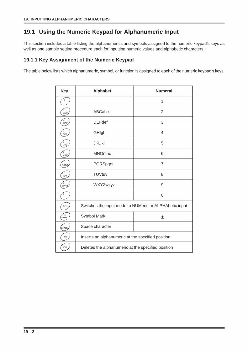
19 – 2
19. INPUTTING ALPHANUMERIC CHARACTERS
19.1 Using the Numeric Keypad for Alphanumeric Input
This section includes a table listing the alphanumerics and symbols assigned to the numeric keypad’s keys aswell as one sample setting procedure each for inputting numeric values and alphabetic characters.
19.1.1 Key Assignment of the Numeric Keypad
The table below lists which alphanumeric, symbol, or function is assigned to each of the numeric keypad’s keys.
Key Alphabet Numeral
1
ABCabc 2
DEFdef 3
GHIghi 4
JKLjkl 5
MNOmno 6
PQRSpqrs 7
TUVtuv 8
WXYZwxyz 9
0
Switches the input mode to NUMeric or ALPHAbetic input
Symbol Mark
Space character
Inserts an alphanumeric at the specified position
Deletes the alphanumeric at the specified position
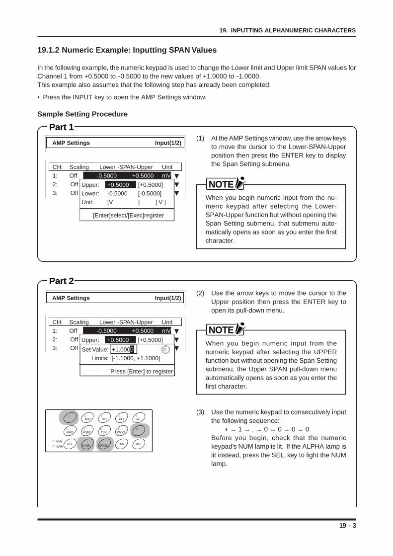
19 – 3
19. INPUTTING ALPHANUMERIC CHARACTERS
Part 1
Part 2
19.1.2 Numeric Example: Inputting SPAN Values
In the following example, the numeric keypad is used to change the Lower limit and Upper limit SPAN values forChannel 1 from +0.5000 to -0.5000 to the new values of +1.0000 to -1.0000.This example also assumes that the following step has already been completed:
• Press the INPUT key to open the AMP Settings window.
Sample Setting Procedure
(1) At the AMP Settings window, use the arrow keysto move the cursor to the Lower-SPAN-Upperposition then press the ENTER key to displaythe Span Setting submenu.
NOTEWhen you begin numeric input from the nu-meric keypad after selecting the Lower-SPAN-Upper function but without opening theSpan Setting submenu, that submenu auto-matically opens as soon as you enter the firstcharacter.
(2) Use the arrow keys to move the cursor to theUpper position then press the ENTER key toopen its pull-down menu.
NOTEWhen you begin numeric input from thenumeric keypad after selecting the UPPERfunction but without opening the Span Settingsubmenu, the Upper SPAN pull-down menuautomatically opens as soon as you enter thefirst character.
(3) Use the numeric keypad to consecutively inputthe following sequence:
+ → 1 → . → 0 → 0 → 0 → 0Before you begin, check that the numerickeypad’s NUM lamp is lit. If the ALPHA lamp islit instead, press the SEL. key to light the NUMlamp.
CH: Scaling Lower -SPAN-Upper Unit
1: Off -0.5000 +0.5000 mV
2: Off -0.5000 +0.5000 V
3: Off -1.0000 +1.0000 VUpper: +0.5000 [+0.5000]
Lower: -0.5000 [-0.5000]
Unit: [V ] [ V ]
[Enter]select/[Exec]register
AMP Settings Input(1/2)
CH: Scaling Lower -SPAN-Upper Unit
1: Off -0.5000 +0.5000 mV
2: Off -0.5000 +0.5000 V
3: Off -1.0000 +1.0000 V
AMP Settings Input(1/2)
Upper: +0.5000 [+0.5000]
Lower: -0.5000 [-0.5000]
Unit: [V ] [ V ]
[Enter]select/[Exec]register
Set Value: +1.0000
Limits: [-1.1000, +1.1000]
Press [Enter] to register
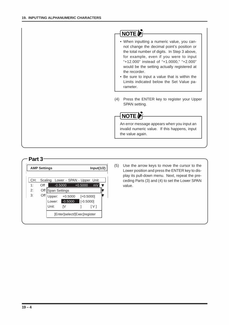
19 – 4
19. INPUTTING ALPHANUMERIC CHARACTERS
Part 3
NOTE• When inputting a numeric value, you can-
not change the decimal point’s position orthe total number of digits. In Step 3 above,for example, even if you were to input“+12.000” instead of “+1.0000,” “+2.000”would be the setting actually registered atthe recorder.
• Be sure to input a value that is within theLimits indicated below the Set Value pa-rameter.
(4) Press the ENTER key to register your UpperSPAN setting.
NOTEAn error message appears when you input aninvalid numeric value. If this happens, inputthe value again.
(5) Use the arrow keys to move the cursor to theLower position and press the ENTER key to dis-play its pull-down menu. Next, repeat the pre-ceding Parts (3) and (4) to set the Lower SPANvalue.
CH: Scaling Lower - SPAN - Upper Unit
1: Off -0.5000 +0.5000 mV
2: Off -0.5000 +0.5000 V
3: Off -1.0000 +1.0000 V
AMP Settings Input(1/2)
Span Settings
Upper: +0.5000 [+0.5000]
Lower: -0.5000 [-0.5000]
Unit: [V ] [ V ]
[Enter]select/[Exec]register
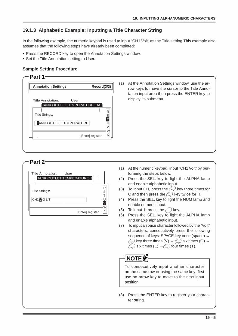
19 – 5
19. INPUTTING ALPHANUMERIC CHAR ACTERS
Part 1
Part 2
19.1.3 Alphabetic Example: Inputting a Title Character String
In the following example, the numeric keypad is used to input “CH1 Volt” as the Title setting.This example alsoassumes that the following steps have already been completed:
• Press the RECORD key to open the Annotation Settings window.• Set the Title Annotation setting to User.
Sample Setting P rocedure
(1) At the Annotation Settings window, use the ar-row keys to move the cursor to the Title Anno-tation input area then press the ENTER key todisplay its submenu.
(1) At the numeric keypad, input “CH1 Volt” by per-forming the steps below.
(2) Press the SEL. key to light the ALPHA lampand enable alphabetic input.
(3) To input CH, press the key three times forC and then press the key twice for H.
(4) Press the SEL. key to light the NUM lamp andenable numeric input.
(5) To input 1, press the key.(6) Press the SEL. key to light the ALPHA lamp
and enable alphabetic input.(7) To input a space character followed by the “Volt”
characters, consecutively press the followingsequence of keys: SPACE key once (space) →
key three times (V) → six times (O) → six times (L) → four times (T).
NOTETo consecutively input another characteron the same row or using the same key, firstuse an arrow key to move to the next inputposition.
(8) Press the ENTER key to register your charac-ter string.
Annotation Settings Record(3/3)
TANK OUTLET TEMPERATURE
RSTUVWX[Enter] register
Title Strings:
Title Annotation: User
[TANK OUTLET TEMPERATURE DAT]
[ ]
Title Annotation: User
[ TANK OUTLET TEMPERATURE DAT]
[ ]
CH1 V O L T
RSTUVWX[Enter] register
Title Strings:
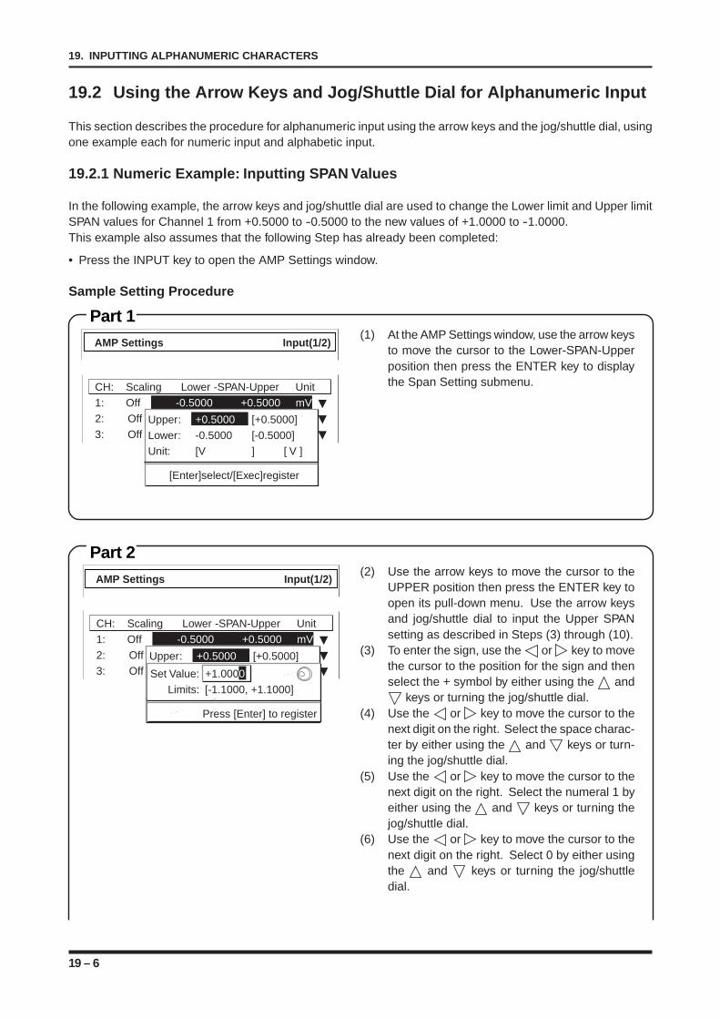
19 – 6
19. INPUTTING ALPHANUMERIC CHARACTERS
Part 1
Part 2
19.2 Using the Arrow Keys and Jog/Shuttle Dial for Alphanumeric Input
This section describes the procedure for alphanumeric input using the arrow keys and the jog/shuttle dial, usingone example each for numeric input and alphabetic input.
19.2.1 Numeric Example: Inputting SPAN Values
In the following example, the arrow keys and jog/shuttle dial are used to change the Lower limit and Upper limitSPAN values for Channel 1 from +0.5000 to -0.5000 to the new values of +1.0000 to -1.0000.This example also assumes that the following Step has already been completed:
• Press the INPUT key to open the AMP Settings window.
Sample Setting Procedure
(1) At the AMP Settings window, use the arrow keysto move the cursor to the Lower-SPAN-Upperposition then press the ENTER key to displaythe Span Setting submenu.
(2) Use the arrow keys to move the cursor to theUPPER position then press the ENTER key toopen its pull-down menu. Use the arrow keysand jog/shuttle dial to input the Upper SPANsetting as described in Steps (3) through (10).
(3) To enter the sign, use the or key to movethe cursor to the position for the sign and thenselect the + symbol by either using the and
keys or turning the jog/shuttle dial.(4) Use the or key to move the cursor to the
next digit on the right. Select the space charac-ter by either using the and keys or turn-ing the jog/shuttle dial.
(5) Use the or key to move the cursor to thenext digit on the right. Select the numeral 1 byeither using the and keys or turning thejog/shuttle dial.
(6) Use the or key to move the cursor to thenext digit on the right. Select 0 by either usingthe and keys or turning the jog/shuttledial.
CH: Scaling Lower -SPAN-Upper Unit
1: Off -0.5000 +0.5000 mV
2: Off -0.5000 +0.5000 V
3: Off -1.0000 +1.0000 VUpper: +0.5000 [+0.5000]
Lower: -0.5000 [-0.5000]
Unit: [V ] [ V ]
[Enter]select/[Exec]register
AMP Settings Input(1/2)
CH: Scaling Lower -SPAN-Upper Unit
1: Off -0.5000 +0.5000 mV
2: Off -0.5000 +0.5000 V
3: Off -1.0000 +1.0000 V
AMP Settings Input(1/2)
Upper: +0.5000 [+0.5000]
Lower: -0.5000 [-0.5000]
Unit: [V ] [ V ]
[Enter]select/[Exec]register
Set Value: +1.0000
Limits: [-1.1000, +1.1000]
Press [Enter] to register
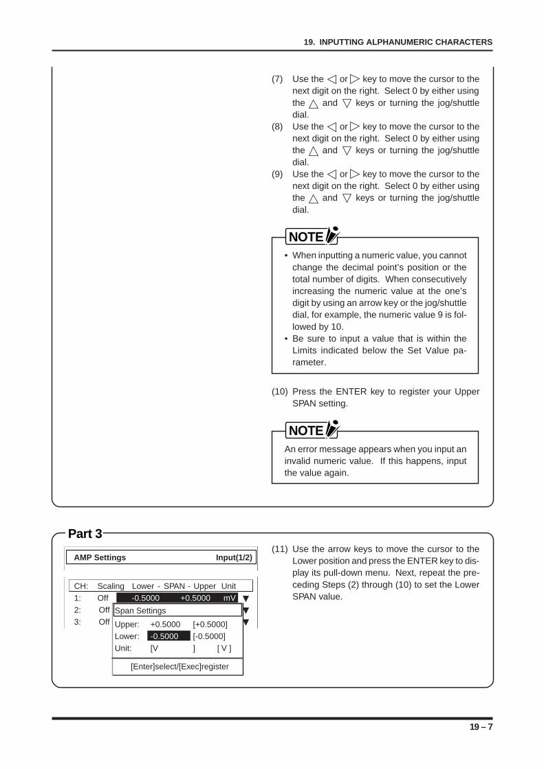
19 – 7
19. INPUTTING ALPHANUMERIC CHARACTERS
(7) Use the or key to move the cursor to thenext digit on the right. Select 0 by either usingthe and keys or turning the jog/shuttledial.
(8) Use the or key to move the cursor to thenext digit on the right. Select 0 by either usingthe and keys or turning the jog/shuttledial.
(9) Use the or key to move the cursor to thenext digit on the right. Select 0 by either usingthe and keys or turning the jog/shuttledial.
NOTE• When inputting a numeric value, you cannot
change the decimal point’s position or thetotal number of digits. When consecutivelyincreasing the numeric value at the one’sdigit by using an arrow key or the jog/shuttledial, for example, the numeric value 9 is fol-lowed by 10.
• Be sure to input a value that is within theLimits indicated below the Set Value pa-rameter.
(10) Press the ENTER key to register your UpperSPAN setting.
NOTEAn error message appears when you input aninvalid numeric value. If this happens, inputthe value again.
Part 3(11) Use the arrow keys to move the cursor to the
Lower position and press the ENTER key to dis-play its pull-down menu. Next, repeat the pre-ceding Steps (2) through (10) to set the LowerSPAN value.
CH: Scaling Lower - SPAN - Upper Unit
1: Off -0.5000 +0.5000 mV
2: Off -0.5000 +0.5000 V
3: Off -1.0000 +1.0000 V
AMP Settings Input(1/2)
Span Settings
Upper: +0.5000 [+0.5000]
Lower: -0.5000 [-0.5000]
Unit: [V ] [ V ]
[Enter]select/[Exec]register
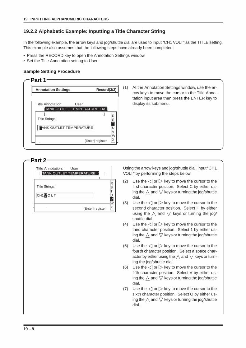
19 – 8
19. INPUTTING ALPHANUMERIC CHARACTERS
Part 2
19.2.2 Alphabetic Example: Inputting a Title Character String
In the following example, the arrow keys and jog/shuttle dial are used to input “CH1 VOLT” as the TITLE setting.This example also assumes that the following steps have already been completed:
• Press the RECORD key to open the Annotation Settings window.• Set the Title Annotation setting to User.
Sample Setting Procedure
Using the arrow keys and jog/shuttle dial, input “CH1VOLT” by performing the steps below.
(2) Use the or key to move the cursor to thefirst character position. Select C by either us-ing the and keys or turning the jog/shuttledial.
(3) Use the or key to move the cursor to thesecond character position. Select H by eitherusing the and keys or turning the jog/shuttle dial.
(4) Use the or key to move the cursor to thethird character position. Select 1 by either us-ing the and keys or turning the jog/shuttledial.
(5) Use the or key to move the cursor to thefourth character position. Select a space char-acter by either using the and keys or turn-ing the jog/shuttle dial.
(6) Use the or key to move the cursor to thefifth character position. Select V by either us-ing the and keys or turning the jog/shuttledial.
(7) Use the or key to move the cursor to thesixth character position. Select O by either us-ing the and keys or turning the jog/shuttledial.
Title Annotation: User
[ TANK OUTLET TEMPERATURE DAT]
[ ]
CH1 V O L T
RSTUVWX[Enter] register
Title Strings:
Part 1(1) At the Annotation Settings window, use the ar-
row keys to move the cursor to the Title Anno-tation input area then press the ENTER key todisplay its submenu.
Annotation Settings Record(3/3)
TANK OUTLET TEMPERATURE
RSTUVWX[Enter] register
Title Strings:
Title Annotation: User
[TANK OUTLET TEMPERATURE DAT]
[ ]
19 – 9
19. INPUTTING ALPHANUMERIC CHARACTERS
(8) Use the or key to move the cursor to theseventh character position. Select L by eitherusing the and keys or turning the jog/shuttle dial.
(9) Use the or key to move the cursor to theeighth character position. Select T by eitherusing the and keys or turning the jog/shuttle dial.
NOTEIf you turn the jog/shuttle dial without usingthe arrow keys to move to a different charac-ter position, the currently selected characterwill be changed.
(10) Press the ENTER key to register your Title An-notation character string.

19 – 10
19. INPUTTING ALPHANUMERIC CHARACTERS
20 – 1
20. PERFORMING CURSOR OPERATIONS
CHAPTER 20CHAPTER 20PERFORMING CURSOR OPERATIONS
This chapter describes how to perform various types ofcursor-related operations.
20.1 Overview of the Cursor Functions20.1.1 Types of Cursor Functions20.2 The Cursor Display20.2.1 When the Display Mode Setting is Y-T20.2.2 When the Display Mode Setting is X-Y20.3 The Display Position of Cursor Information20.3.1 When the Display Mode Setting is Y-T20.3.2 When the Display Mode Setting is X-Y20.4 Using the Cursor-Controlled Scroll Function20.5 Using the Cursor Readout Function20.6 Expanding/Compressing the Cursor-Defined Range of
the Waveform Display to the Screen’s Width20.7 Printing Data within a Cursor-Defined Range20.8 Saving a Cursor-Defined Range of Data to Disk20.9 Saving the Cursor Position20.10 Loading a Cursor Position20.11 Other Cursor Functions20.11.1 Moving to the Beginning of Replay Data20.11.2 Moving to the End of Replay Data20.11.3 Moving to a Cursor-Defined Position (within
Replay Data)20.11.4 Moving the Cursor to a Selected Time (within
Replay Data)20.11.5 Summoning the Other Cursor
20 – 2
20. PERFORMING CURSOR OPERATIONS
20.1 Overview of Cursor Functions
This section describes the types of cursor functions and restrictions on their use. The cursor functions can onlybe used during the replay of data that was captured in RECORDER mode.
20.1.1 Types of Cursor Functions
The cursor types and functions available vary with the Display Mode setting in the Record Settings window.
When the Display Mode Setting is Y-T
Scroll
The jog/shuttle dial can be used to scroll the display of memory data (data that has been captured in therecorder’s internal memory) being displayed on the screen.
Cursor Readout
The electrical potential, time, and frequency values (frequency difference) of the signal input indicated bythe waveform cursor(s) are displayed at the top of the screen or in the Monitor window to the right.
Cursor-defined Zoom
Expands or reduces the memory data within the range specified by the waveform cursors.
Printer Output
Prints the memory data within the range specified by the waveform cursors.
Cursor-defined Save operation
Saves the memory data within the range specified by the waveform cursors to a floppy disk or (if installed)another memory device such as a hard disk or magneto-optic disk.
Save/Load Cursor Position
Saves the position of the waveform cursor or loads a waveform cursor position that has been previouslysaved.
When the Display Mode Setting is X-Y
Cursor Readout
Displays the electrical potential of the signal input at the position indicated by the waveform cursor(s) at theright side of the screen (the X-axis values) and the lower part of the screen (the Y-axis values).
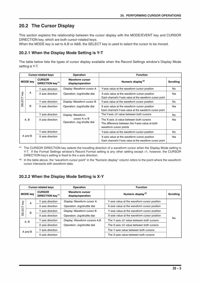
20 – 3
20. PERFORMING CURSOR OPERATIONS
20.2 The Cursor Display
This section explains the relationship between the cursor display with the MODE/EVENT key and CURSORDIRECTION key, which are both cursor-related keys.When the MODE key is set to A,B or A&B, the SELECT key is used to select the cursor to be moved.
20.2.1 When the Display Mode Setting is Y-T
The table below lists the types of cursor display available when the Record Settings window’s Display Modesetting is Y-T.
MODE keyCURSOR DIRECTION key*1
Waveform cursor display/operation
Numeric display*2 Scrolling
X axis direction
Y axis direction
X axis direction
Y axis direction
X axis direction
Y axis direction
X axis direction
Y axis direction
Display: Waveform cursor A
Operation: Jog/shuttle dial
Display: Waveform cursor B
Operation: Jog/shuttle dial
Display: Waveform cursor A or B
Operation: Jog shuttle dial
Y-axis value at the waveform cursor position
X-axis value at the waveform cursor position Each channel’s Y-axis value at the waveform cursor point
Y-axis value at the waveform cursor position
X-axis value at the waveform cursor position Each channel’s Y-axis value at the waveform cursor point
The Y-axis ∆V value between both cursors
The X-axis ∆t value between both cursors The difference between the Y-axis value at both waveform cursor points
Y-axis value at the waveform cursor position
X-axis value at the waveform cursor position Each channel’s Y-axis value at the waveform cursor point
No
Yes
No
Yes
Yes
No
No
Yes
A
B
A, B
A and B
Cursor-related keys Operation Function
SE
LEC
T k
ey
*1 The CURSOR DIRECTION key selects the travelling direction of a waveform cursor when the Display Mode setting isY-T. If the Format Settings window’s Record Format setting is any other setting except ×1, however, the CURSORDIRECTION key’s setting is fixed to the x-axis direction.
*2 In the table above, the “waveform cursor point” in the “Numeric display” column refers to the point where the waveformcursor intersects with waveform data.
20.2.2 When the Display Mode Setting is X-Y
MODE keyCURSOR DIRECTION key*1
Waveform cursor display/operation
Numeric display*2 Scrolling
X axis direction
Y axis direction
Operation: Jog/shuttle dial
Display: Waveform cursor A
X-axis value at the waveform cursor position
Y-axis value at the waveform cursor position
X axis direction
Y axis direction
X axis direction
Y axis direction
X axis direction
Y axis direction
Operation: Jog/shuttle dial
Display: Waveform cursor B
Operation: Jog/shuttle dial
Display: Waveform cursors A,B
The X-axis ∆V value between both cursors
The Y-axis ∆V value between both cursors
The X-axis value between both cursors
The Y-axis value between both cursors
X-axis value at the waveform cursor position
Y-axis value at the waveform cursor position
No
A
B
A, B
A and B
Cursor-related keys Operation Function
SE
LEC
T k
ey
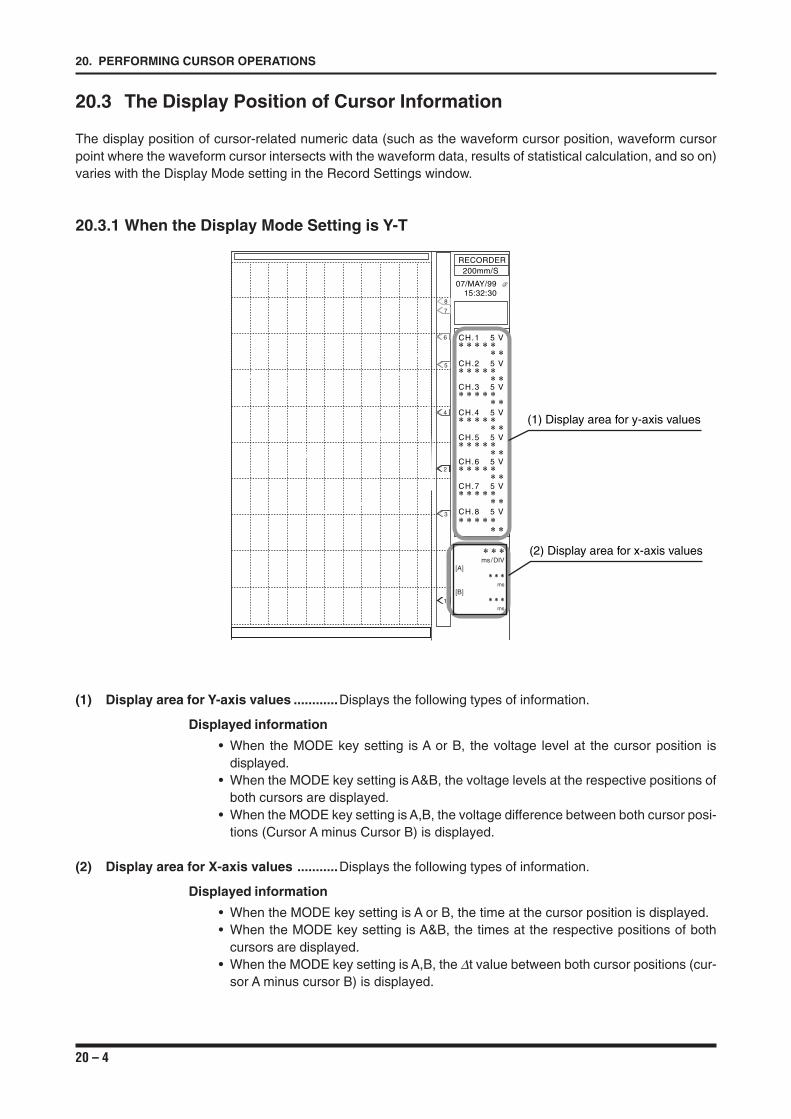
20 – 4
20. PERFORMING CURSOR OPERATIONS
20.3 The Display Position of Cursor Information
The display position of cursor-related numeric data (such as the waveform cursor position, waveform cursorpoint where the waveform cursor intersects with the waveform data, results of statistical calculation, and so on)varies with the Display Mode setting in the Record Settings window.
20.3.1 When the Display Mode Setting is Y-T
1
2
3
4
5
6
7
8
∗ ∗ ∗ms/DIV
[A]∗ ∗ ∗
ms
[B]∗ ∗ ∗
ms
RECORDER200mm/S
07/MAY/99 @15:32:30
CH.1 5 V∗ ∗ ∗ ∗ ∗
∗ ∗CH.2 5 V∗ ∗ ∗ ∗ ∗
∗ ∗CH.3 5 V∗ ∗ ∗ ∗ ∗
∗ ∗CH.4 5 V∗ ∗ ∗ ∗ ∗
∗ ∗CH.5 5 V∗ ∗ ∗ ∗ ∗
∗ ∗
CH.7 5 V∗ ∗ ∗ ∗ ∗
∗ ∗CH.8 5 V∗ ∗ ∗ ∗ ∗
∗ ∗
CH.6 5 V∗ ∗ ∗ ∗ ∗
∗ ∗
(1) Display area for y-axis values
(2) Display area for x-axis values
(1) Display area for Y-axis values ............Displays the following types of information.
Displayed information
• When the MODE key setting is A or B, the voltage level at the cursor position isdisplayed.
• When the MODE key setting is A&B, the voltage levels at the respective positions ofboth cursors are displayed.
• When the MODE key setting is A,B, the voltage difference between both cursor posi-tions (Cursor A minus Cursor B) is displayed.
(2) Display area for X-axis values ...........Displays the following types of information.
Displayed information
• When the MODE key setting is A or B, the time at the cursor position is displayed.• When the MODE key setting is A&B, the times at the respective positions of both
cursors are displayed.• When the MODE key setting is A,B, the ∆t value between both cursor positions (cur-
sor A minus cursor B) is displayed.
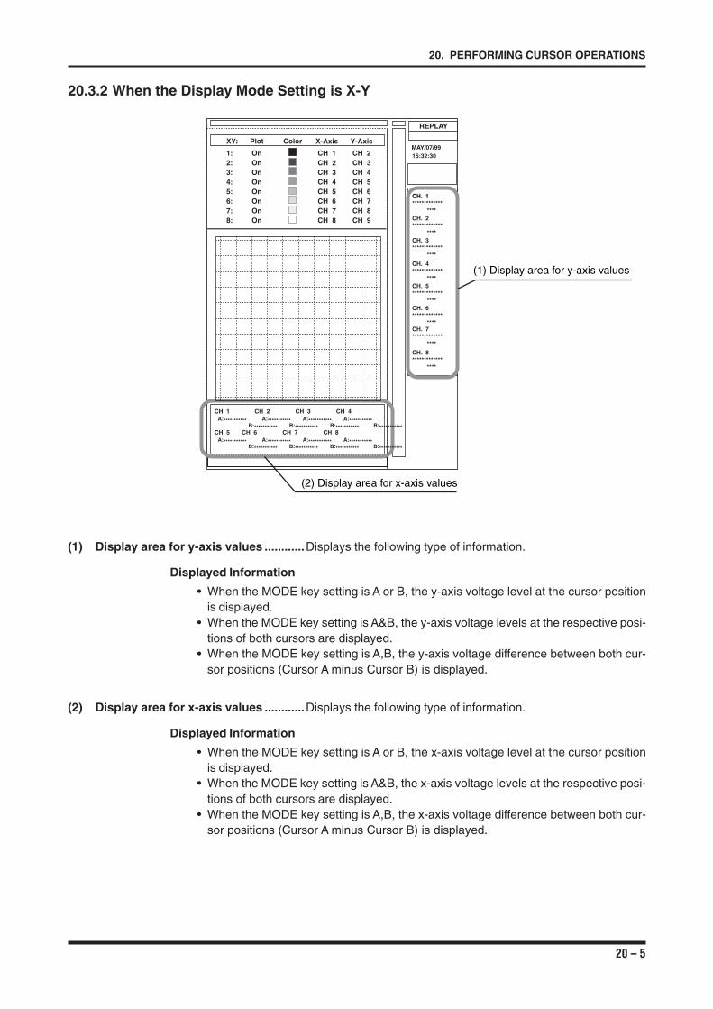
20 – 5
20. PERFORMING CURSOR OPERATIONS
20.3.2 When the Display Mode Setting is X-Y
(1) Display area for y-axis values ............Displays the following type of information.
Displayed Information
• When the MODE key setting is A or B, the y-axis voltage level at the cursor positionis displayed.
• When the MODE key setting is A&B, the y-axis voltage levels at the respective posi-tions of both cursors are displayed.
• When the MODE key setting is A,B, the y-axis voltage difference between both cur-sor positions (Cursor A minus Cursor B) is displayed.
(2) Display area for x-axis values ............Displays the following type of information.
Displayed Information
• When the MODE key setting is A or B, the x-axis voltage level at the cursor positionis displayed.
• When the MODE key setting is A&B, the x-axis voltage levels at the respective posi-tions of both cursors are displayed.
• When the MODE key setting is A,B, the x-axis voltage difference between both cur-sor positions (Cursor A minus Cursor B) is displayed.
REPLAY
CH. 1*************
****CH. 2*************
****CH. 3*************
****
CH. 4*************
****CH. 5*************
****CH. 6*************
****CH. 7*************
****
CH. 8*************
****
MAY/07/9915:32:30
XY: Plot Color X-Axis Y-Axis
1: On CH 1 CH 22: On CH 2 CH 33: On CH 3 CH 44: On CH 4 CH 55: On CH 5 CH 66: On CH 6 CH 77: On CH 7 CH 88: On CH 8 CH 9
CH 1 CH 2 CH 3 CH 4A:*********** A:*********** A:*********** A:***********
B:*********** B:*********** B:*********** B:***********CH 5 CH 6 CH 7 CH 8
A:*********** A:*********** A:*********** A:***********B:*********** B:*********** B:*********** B:***********
(2) Display area for x-axis values
(1) Display area for y-axis values
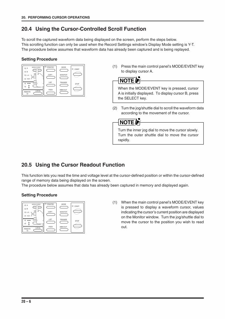
20 – 6
20. PERFORMING CURSOR OPERATIONS
20.4 Using the Cursor-Controlled Scroll Function
To scroll the captured waveform data being displayed on the screen, perform the steps below.This scrolling function can only be used when the Record Settings window’s Display Mode setting is Y-T.The procedure below assumes that waveform data has already been captured and is being replayed.
Setting Procedure
(1) Press the main control panel’s MODE/EVENT keyto display cursor A.
NOTEWhen the MODE/EVENT key is pressed, cursorA is initially displayed. To display cursor B, pressthe SELECT key.
(2) Turn the jog/shuttle dial to scroll the waveform dataaccording to the movement of the cursor.
NOTETurn the inner jog dial to move the cursor slowly.Turn the outer shuttle dial to move the cursorrapidly.
20.5 Using the Cursor Readout Function
This function lets you read the time and voltage level at the cursor-defined position or within the cursor-definedrange of memory data being displayed on the screen.The procedure below assumes that data has already been captured in memory and displayed again.
Setting Procedure
(1) When the main control panel’s MODE/EVENT keyis pressed to display a waveform cursor, valuesindicating the cursor’s current position are displayedon the Monitor window. Turn the jog/shuttle dial tomove the cursor to the position you wish to readout.
MODE/ EVENT
SELECT
A
B
A, B
A&B
PRINTER
COPY
LIST
FEED
MODE
MONITOR
TRIGGER
MEM.OUT
START
STOP
LOCALREMOTE
CURSOR
DIRECTION
MODE/ EVENT
SELECT
A
B
A, B
A&B
PRINTER
COPY
LIST
FEED
MODE
MONITOR
TRIGGER
MEM.OUT
START
STOP
LOCALREMOTE
CURSOR
DIRECTION
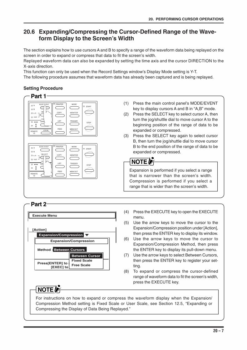
20 – 7
20. PERFORMING CURSOR OPERATIONS
20.6 Expanding/Compressing the Cursor-Defined Range of the Wave-form Display to the Screen’s Width
The section explains how to use cursors A and B to specify a range of the waveform data being replayed on thescreen in order to expand or compress that data to fit the screen’s width.Replayed waveform data can also be expanded by setting the time axis and the cursor DIRECTION to theX-axis direction.This function can only be used when the Record Settings window’s Display Mode setting is Y-T.The following procedure assumes that waveform data has already been captured and is being replayed.
(4) Press the EXECUTE key to open the EXECUTEmenu.
(5) Use the arrow keys to move the cursor to theExpansion/Compression position under [Action],then press the ENTER key to display its window.
(6) Use the arrow keys to move the cursor toExpansion/Compression Method, then pressthe ENTER key to display its pull-down menu.
(7) Use the arrow keys to select Between Cursors,then press the ENTER key to register your set-ting.
(8) To expand or compress the cursor-definedrange of waveform data to fit the screen’s width,press the EXECUTE key.
Execute Menu
[Action]
Expansion/CompressionStatistical CalculationExpansion/Compression
Method : Between Cursors
Press[ENTER] to select[EXEC] to execute
Between CursorFixed ScaleFree Scale
Part 2
Setting Procedure
Part 1(1) Press the main control panel’s MODE/EVENT
key to display cursors A and B in “A,B” mode.(2) Press the SELECT key to select cursor A, then
turn the jog/shuttle dial to move cursor A to thebeginning position of the range of data to beexpanded or compressed.
(3) Press the SELECT key again to select cursorB, then turn the jog/shuttle dial to move cursorB to the end position of the range of data to beexpanded or compressed.
NOTEExpansion is performed if you select a rangethat is narrower than the screen’s width.Compression is performed if you select arange that is wider than the screen’s width.
MODE/EVENT
SELECT
A
B
A, B
A&B
PRINTER
COPY
LIST
FEED
MODE
MONITOR
TRIGGER
MEM.OUT
START
STOP
LOCALREMOTE
CURSOR
DIRECTION
MODE/ EVENT
SELECT
A
B
A, B
A&B
PRINTER
COPY
LIST
FEED
MODE
MONITOR
TRIGGER
MEM.OUT
START
STOP
LOCALREMOTE
CURSOR
DIRECTION
NOTEFor instructions on how to expand or compress the waveform display when the Expansion/Compression Method setting is Fixed Scale or User Scale, see Section 12.5, “Expanding orCompressing the Display of Data Being Replayed.”
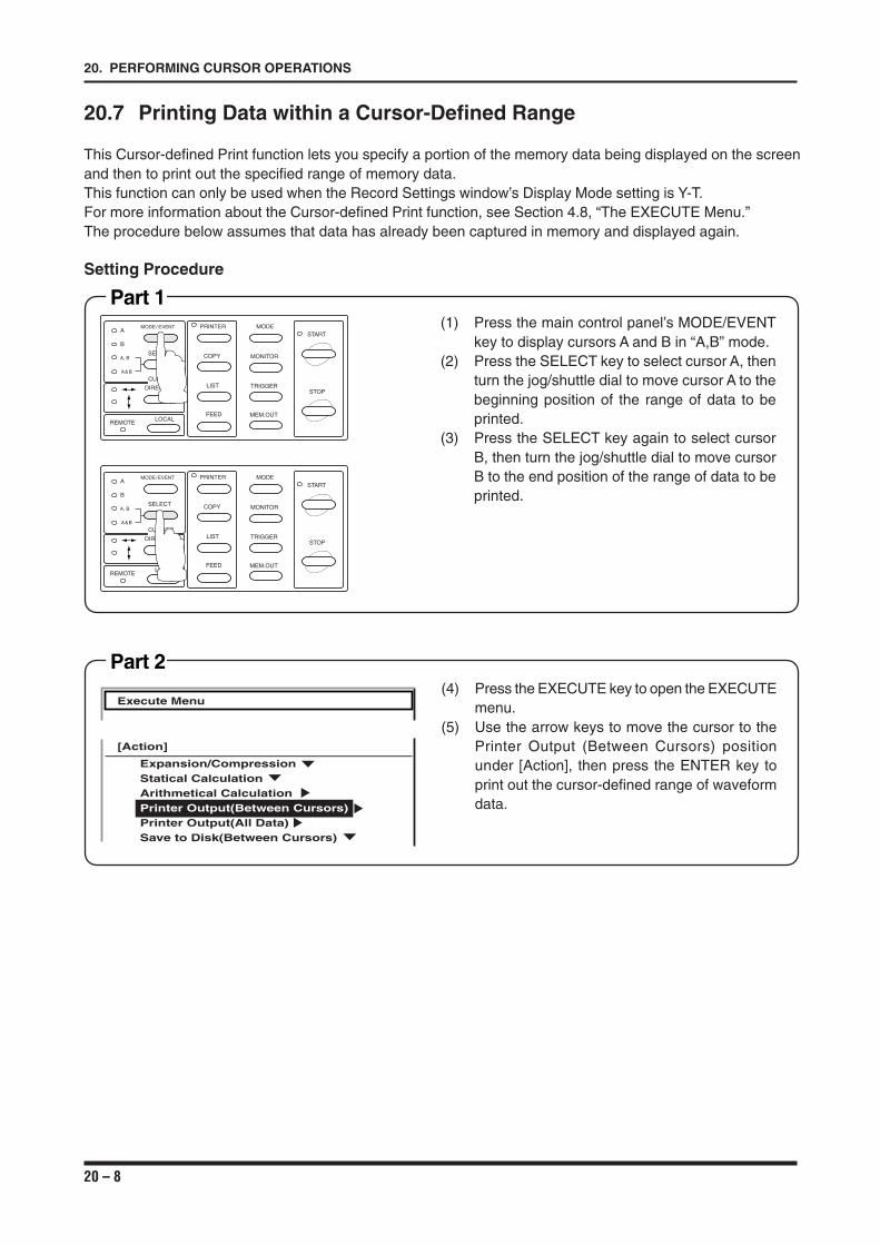
20 – 8
20. PERFORMING CURSOR OPERATIONS
20.7 Printing Data within a Cursor-Defined Range
This Cursor-defined Print function lets you specify a portion of the memory data being displayed on the screenand then to print out the specified range of memory data.This function can only be used when the Record Settings window’s Display Mode setting is Y-T.For more information about the Cursor-defined Print function, see Section 4.8, “The EXECUTE Menu.”The procedure below assumes that data has already been captured in memory and displayed again.
Setting Procedure
Part 1(1) Press the main control panel’s MODE/EVENT
key to display cursors A and B in “A,B” mode.(2) Press the SELECT key to select cursor A, then
turn the jog/shuttle dial to move cursor A to thebeginning position of the range of data to beprinted.
(3) Press the SELECT key again to select cursorB, then turn the jog/shuttle dial to move cursorB to the end position of the range of data to beprinted.
MODE/EVENT
SELECT
A
B
A, B
A&B
PRINTER
COPY
LIST
FEED
MODE
MONITOR
TRIGGER
MEM.OUT
START
STOP
LOCALREMOTE
CURSOR
DIRECTION
MODE/ EVENT
SELECT
A
B
A, B
A&B
PRINTER
COPY
LIST
FEED
MODE
MONITOR
TRIGGER
MEM.OUT
START
STOP
LOCALREMOTE
CURSOR
DIRECTION
Part 2(4) Press the EXECUTE key to open the EXECUTE
menu.(5) Use the arrow keys to move the cursor to the
Printer Output (Between Cursors) positionunder [Action], then press the ENTER key toprint out the cursor-defined range of waveformdata.
Execute Menu
[Action]
Expansion/CompressionStatical CalculationArithmetical CalculationPrinter Output(Between Cursors)Printer Output(All Data)Save to Disk(Between Cursors)
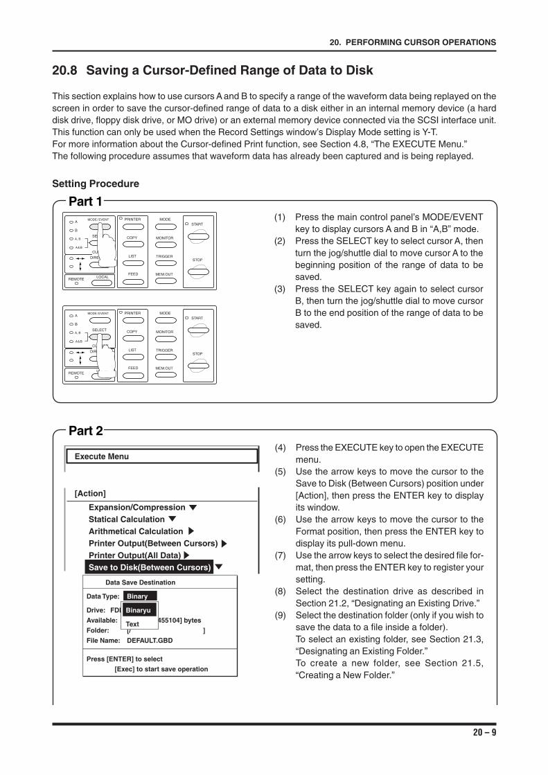
20 – 9
20. PERFORMING CURSOR OPERATIONS
20.8 Saving a Cursor-Defined Range of Data to Disk
This section explains how to use cursors A and B to specify a range of the waveform data being replayed on thescreen in order to save the cursor-defined range of data to a disk either in an internal memory device (a harddisk drive, floppy disk drive, or MO drive) or an external memory device connected via the SCSI interface unit.This function can only be used when the Record Settings window’s Display Mode setting is Y-T.For more information about the Cursor-defined Print function, see Section 4.8, “The EXECUTE Menu.”The following procedure assumes that waveform data has already been captured and is being replayed.
Setting Procedure
Part 1(1) Press the main control panel’s MODE/EVENT
key to display cursors A and B in “A,B” mode.(2) Press the SELECT key to select cursor A, then
turn the jog/shuttle dial to move cursor A to thebeginning position of the range of data to besaved.
(3) Press the SELECT key again to select cursorB, then turn the jog/shuttle dial to move cursorB to the end position of the range of data to besaved.
MODE/EVENT
SELECT
A
B
A, B
A&B
PRINTER
COPY
LIST
FEED
MODE
MONITOR
TRIGGER
MEM.OUT
START
STOP
LOCALREMOTE
CURSOR
DIRECTION
MODE/ EVENT
SELECT
A
B
A, B
A&B
PRINTER
COPY
LIST
FEED
MODE
MONITOR
TRIGGER
MEM.OUT
START
STOP
LOCALREMOTE
CURSOR
DIRECTION
Part 2(4) Press the EXECUTE key to open the EXECUTE
menu.(5) Use the arrow keys to move the cursor to the
Save to Disk (Between Cursors) position under[Action], then press the ENTER key to displayits window.
(6) Use the arrow keys to move the cursor to theFormat position, then press the ENTER key todisplay its pull-down menu.
(7) Use the arrow keys to select the desired file for-mat, then press the ENTER key to register yoursetting.
(8) Select the destination drive as described inSection 21.2, “Designating an Existing Drive.”
(9) Select the destination folder (only if you wish tosave the data to a file inside a folder).To select an existing folder, see Section 21.3,“Designating an Existing Folder.”To create a new folder, see Section 21.5,“Creating a New Folder.”
Execute Menu
[Action]
Expansion/CompressionStatical CalculationArithmetical CalculationPrinter Output(Between Cursors)Printer Output(All Data)Save to Disk(Between Cursors)
Data Save Destination
Data Type: Binary
Drive:AFDD
Available: [ 1455104] bytes
Folder: [/ ]
File Name: DEFAULT.GBD
Press [ENTER] to select
[Exec] to start save operation
Binaryu
Text
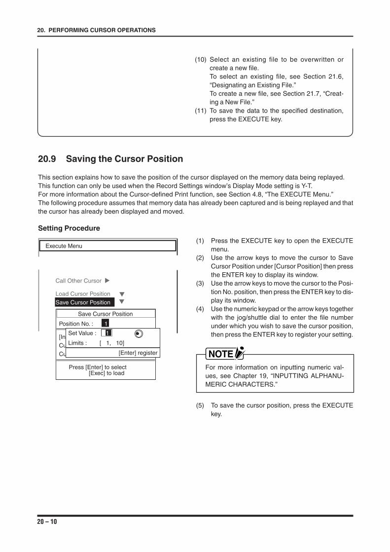
20 – 10
20. PERFORMING CURSOR OPERATIONS
20.9 Saving the Cursor Position
This section explains how to save the position of the cursor displayed on the memory data being replayed.This function can only be used when the Record Settings window’s Display Mode setting is Y-T.For more information about the Cursor-defined Print function, see Section 4.8, “The EXECUTE Menu.”The following procedure assumes that memory data has already been captured and is being replayed and thatthe cursor has already been displayed and moved.
Setting Procedure
(1) Press the EXECUTE key to open the EXECUTEmenu.
(2) Use the arrow keys to move the cursor to SaveCursor Position under [Cursor Position] then pressthe ENTER key to display its window.
(3) Use the arrow keys to move the cursor to the Posi-tion No. position, then press the ENTER key to dis-play its window.
(4) Use the numeric keypad or the arrow keys togetherwith the jog/shuttle dial to enter the file numberunder which you wish to save the cursor position,then press the ENTER key to register your setting.
NOTEFor more information on inputting numeric val-ues, see Chapter 19, “INPUTTING ALPHANU-MERIC CHARACTERS.”
(5) To save the cursor position, press the EXECUTEkey.
Execute Menu
Call Other Cursor
Load Cursor Position
Save Cursor Position
Save Cursor Position
Position No. : 1
[Information]
Cursor A : + 200ms
Cursor B : + 300ms
Press [Enter] to select[Exec] to load
Set Value : 1
Limits : [ 1, 10]
[Enter] register
(10) Select an existing file to be overwritten orcreate a new file.To select an existing file, see Section 21.6,“Designating an Existing File.”To create a new file, see Section 21.7, “Creat-ing a New File.”
(11) To save the data to the specified destination,press the EXECUTE key.
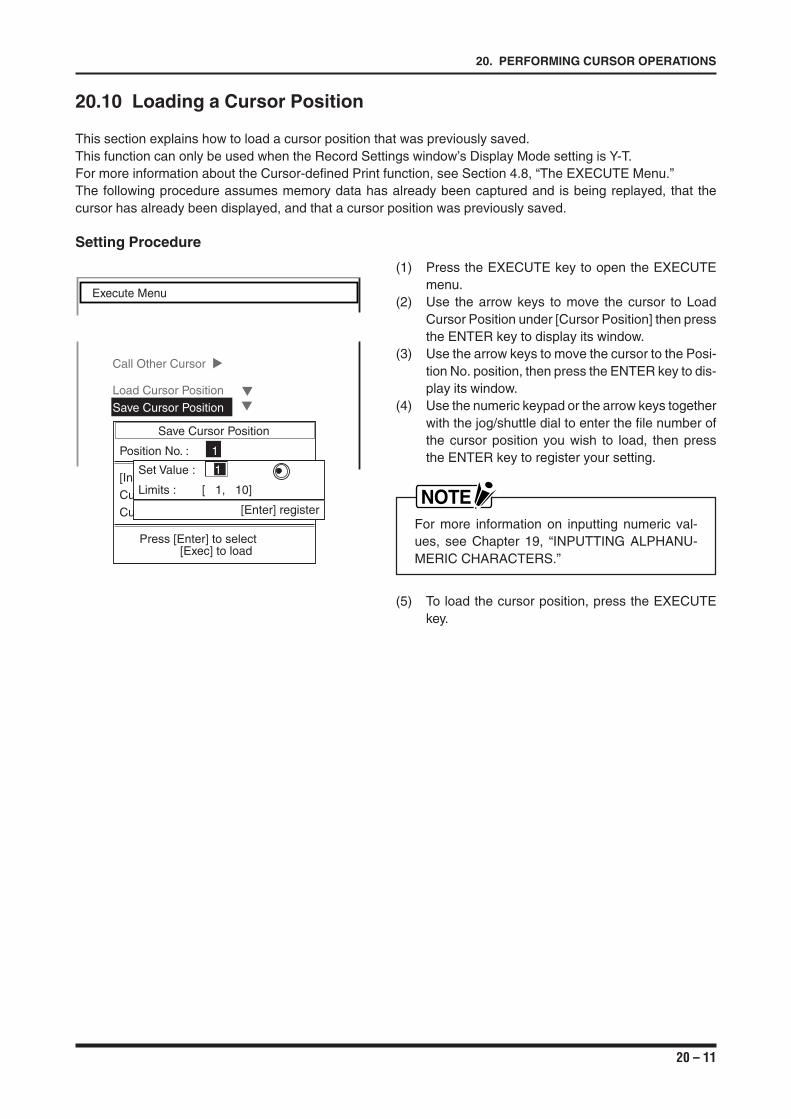
20 – 11
20. PERFORMING CURSOR OPERATIONS
Execute Menu
Call Other Cursor
Load Cursor Position
Save Cursor Position
Save Cursor Position
Position No. : 1
[Information]
Cursor A : + 200ms
Cursor B : + 300ms
Press [Enter] to select[Exec] to load
Set Value : 1
Limits : [ 1, 10]
[Enter] register
20.10 Loading a Cursor Position
This section explains how to load a cursor position that was previously saved.This function can only be used when the Record Settings window’s Display Mode setting is Y-T.For more information about the Cursor-defined Print function, see Section 4.8, “The EXECUTE Menu.”The following procedure assumes memory data has already been captured and is being replayed, that thecursor has already been displayed, and that a cursor position was previously saved.
Setting Procedure
(1) Press the EXECUTE key to open the EXECUTEmenu.
(2) Use the arrow keys to move the cursor to LoadCursor Position under [Cursor Position] then pressthe ENTER key to display its window.
(3) Use the arrow keys to move the cursor to the Posi-tion No. position, then press the ENTER key to dis-play its window.
(4) Use the numeric keypad or the arrow keys togetherwith the jog/shuttle dial to enter the file number ofthe cursor position you wish to load, then pressthe ENTER key to register your setting.
NOTEFor more information on inputting numeric val-ues, see Chapter 19, “INPUTTING ALPHANU-MERIC CHARACTERS.”
(5) To load the cursor position, press the EXECUTEkey.
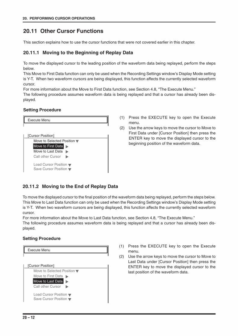
20 – 12
20. PERFORMING CURSOR OPERATIONS
20.11 Other Cursor Functions
This section explains how to use the cursor functions that were not covered earlier in this chapter.
20.11.1 Moving to the Beginning of Replay Data
To move the displayed cursor to the leading position of the waveform data being replayed, perform the stepsbelow.This Move to First Data function can only be used when the Recording Settings window’s Display Mode settingis Y-T. When two waveform cursors are being displayed, this function affects the currently selected waveformcursor.For more information about the Move to First Data function, see Section 4.8, “The Execute Menu.”The following procedure assumes waveform data is being replayed and that a cursor has already been dis-played.
Setting Procedure
(1) Press the EXECUTE key to open the Executemenu.
(2) Use the arrow keys to move the cursor to Move toFirst Data under [Cursor Position] then press theENTER key to move the displayed cursor to thebeginning position of the waveform data.
Execute Menu
[Cursor Position]
Move to Selected Position
Move to First Data
Move to Last Data
Call other Cursor
Load Cursor PositionSave Cursor Position
20.11.2 Moving to the End of Replay Data
To move the displayed cursor to the final position of the waveform data being replayed, perform the steps below.This Move to Last Data function can only be used when the Recording Settings window’s Display Mode settingis Y-T. When two waveform cursors are being displayed, this function affects the currently selected waveformcursor.For more information about the Move to Last Data function, see Section 4.8, “The Execute Menu.”The following procedure assumes waveform data is being replayed and that a cursor has already been dis-played.
Setting Procedure
(1) Press the EXECUTE key to open the Executemenu.
(2) Use the arrow keys to move the cursor to Move toLast Data under [Cursor Position] then press theENTER key to move the displayed cursor to thelast position of the waveform data.
Execute Menu
[Cursor Position]
Move to Selected Position
Move to First Data
Move to Last Data
Call other Cursor
Load Cursor PositionSave Cursor Position

20 – 13
20. PERFORMING CURSOR OPERATIONS
20.11.3 Moving to a Cursor-Defined Position (within Replay Data)
To move the displayed cursor to a specified position, perform the steps below. If two waveform cursors arebeing displayed, this function affects only the currently selected cursor.This function can only be used when the Record Settings window’s Display Mode setting is Y-T.For more information about the Move to Selected Position function, see Section 4.8, “The EXECUTE Menu.”The following procedure assumes waveform data is being replayed and that a cursor has already beendisplayed.
Setting Procedure
Part 1(1) Press the EXECUTE key to open the EXECUTE
menu.(2) Use the arrow keys to move the cursor to Move
to Selected Position under [Cursor Position] thenpress the ENTER key to display its window.
(3) Use the arrow keys to move the cursor to theMethod position, then press the ENTER key todisplay its pull-down menu.
(4) Use the arrow keys to select either Position or%, then press the ENTER key to register yoursetting.
NOTE• The Position parameter is specified as the
lapse of time from the data’s starting posi-tion which is regarded as 0 µs.
• The % parameter is specified on the basisof the data’s first position as 0% and its lastposition as 100%.
Execute Menu
[Cursor Position]
Move to Selected Position
Move to Selected PositionMethod : PositionMove to : +
[Information]Start Point : + 0 sEnd Point : - 1 s
Press [Enter] to select[Exec] to register
Position
Time
Percent
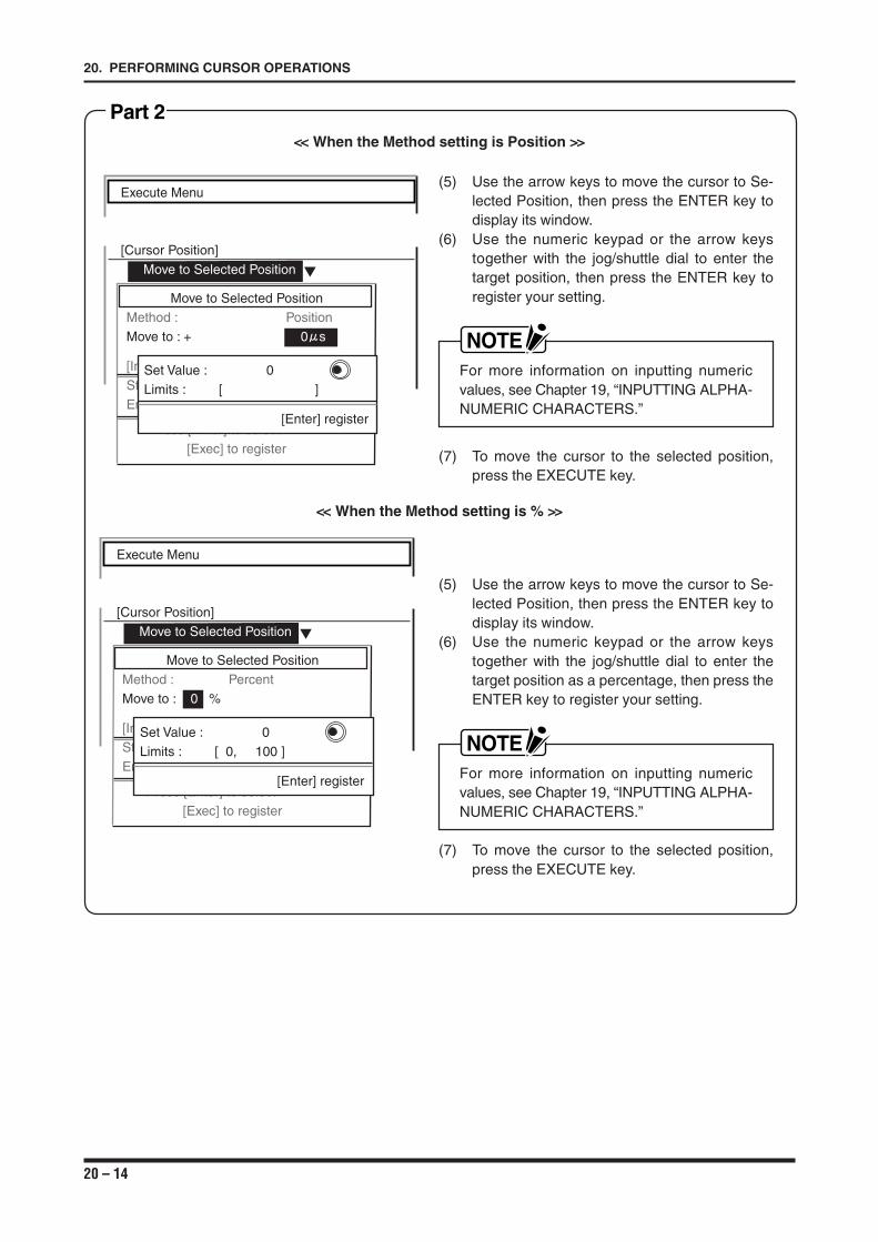
20 – 14
20. PERFORMING CURSOR OPERATIONS
(5) Use the arrow keys to move the cursor to Se-lected Position, then press the ENTER key todisplay its window.
(6) Use the numeric keypad or the arrow keystogether with the jog/shuttle dial to enter thetarget position as a percentage, then press theENTER key to register your setting.
NOTEFor more information on inputting numericvalues, see Chapter 19, “INPUTTING ALPHA-NUMERIC CHARACTERS.”
(7) To move the cursor to the selected position,press the EXECUTE key.
<< When the Method setting is % >>
Execute Menu
[Cursor Position]
Move to Selected Position
Move to Selected PositionMethod : PercentMove to : 0 %
[Information]Start Point : + 0 sEnd Point : - 1 s
Press [Enter] to select[Exec] to register
Set Value : 0Limits : [ 0, 100 ]
[Enter] register
Part 2
(5) Use the arrow keys to move the cursor to Se-lected Position, then press the ENTER key todisplay its window.
(6) Use the numeric keypad or the arrow keystogether with the jog/shuttle dial to enter thetarget position, then press the ENTER key toregister your setting.
NOTEFor more information on inputting numericvalues, see Chapter 19, “INPUTTING ALPHA-NUMERIC CHARACTERS.”
(7) To move the cursor to the selected position,press the EXECUTE key.
Execute Menu
[Cursor Position]
Move to Selected Position
Move to Selected PositionMethod : PositionMove to : + 0 s
[Information]Start Point : + 0 sEnd Point : - 1 s
Press [Enter] to select[Exec] to register
Set Value : 0Limits : [ ]
[Enter] register
<< When the Method setting is Position >>
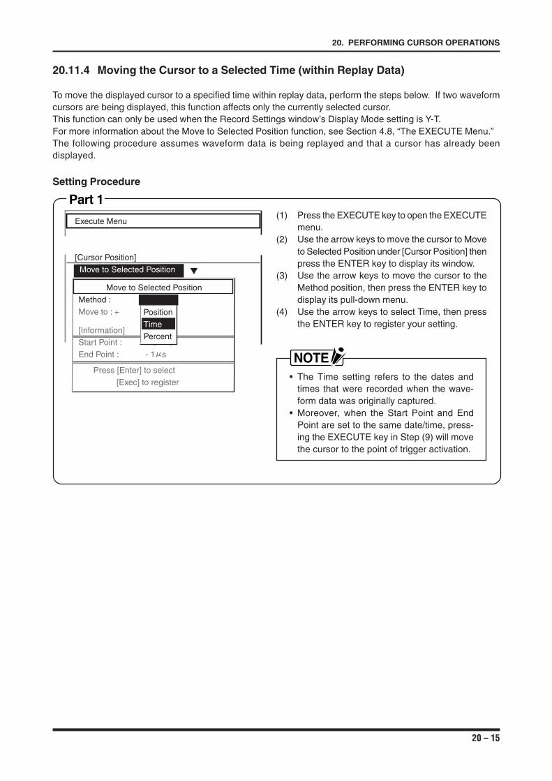
20 – 15
20. PERFORMING CURSOR OPERATIONS
20.11.4 Moving the Cursor to a Selected Time (within Replay Data)
To move the displayed cursor to a specified time within replay data, perform the steps below. If two waveformcursors are being displayed, this function affects only the currently selected cursor.This function can only be used when the Record Settings window’s Display Mode setting is Y-T.For more information about the Move to Selected Position function, see Section 4.8, “The EXECUTE Menu.”The following procedure assumes waveform data is being replayed and that a cursor has already beendisplayed.
Setting Procedure
Part 1(1) Press the EXECUTE key to open the EXECUTE
menu.(2) Use the arrow keys to move the cursor to Move
to Selected Position under [Cursor Position] thenpress the ENTER key to display its window.
(3) Use the arrow keys to move the cursor to theMethod position, then press the ENTER key todisplay its pull-down menu.
(4) Use the arrow keys to select Time, then pressthe ENTER key to register your setting.
NOTE• The Time setting refers to the dates and
times that were recorded when the wave-form data was originally captured.
• Moreover, when the Start Point and EndPoint are set to the same date/time, press-ing the EXECUTE key in Step (9) will movethe cursor to the point of trigger activation.
Execute Menu
[Cursor Position]
Move to Selected Position
Move to Selected PositionMethod : TimeMove to : +
[Information]Start Point : + 0 sEnd Point : - 1 s
Press [Enter] to select[Exec] to register
Position
Time
Percent
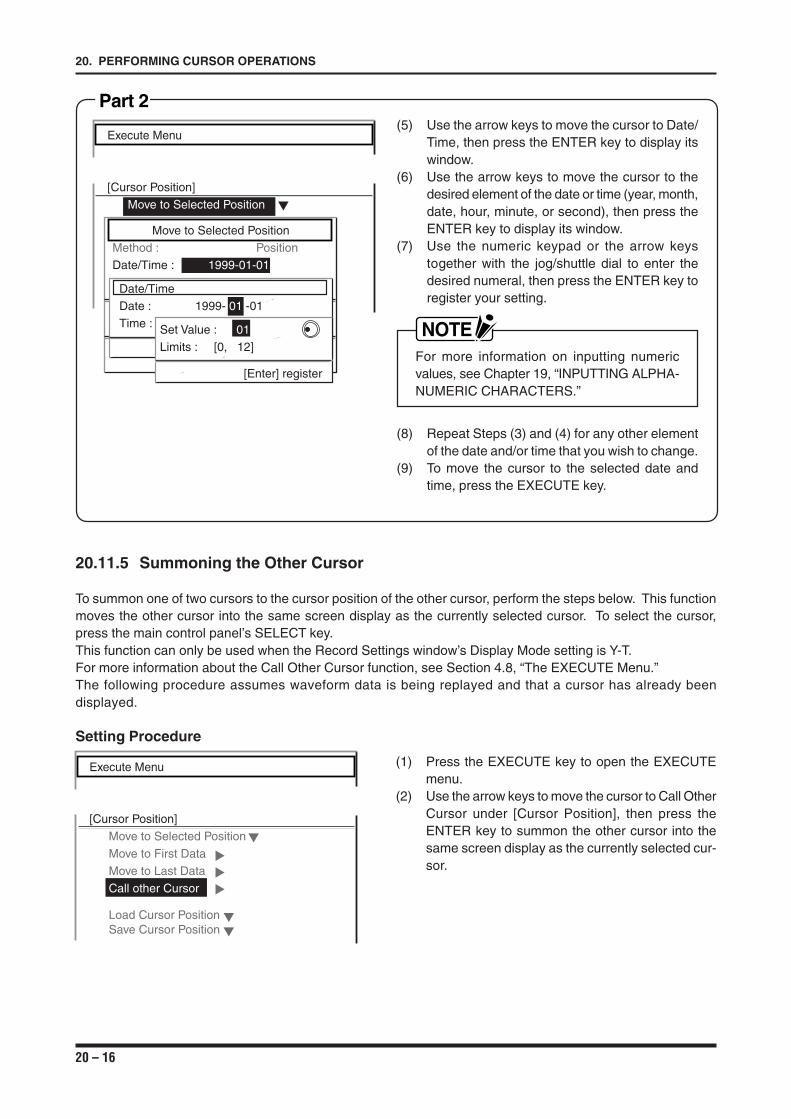
20 – 16
20. PERFORMING CURSOR OPERATIONS
20.11.5 Summoning the Other Cursor
To summon one of two cursors to the cursor position of the other cursor, perform the steps below. This functionmoves the other cursor into the same screen display as the currently selected cursor. To select the cursor,press the main control panel’s SELECT key.This function can only be used when the Record Settings window’s Display Mode setting is Y-T.For more information about the Call Other Cursor function, see Section 4.8, “The EXECUTE Menu.”The following procedure assumes waveform data is being replayed and that a cursor has already beendisplayed.
Setting Procedure
(1) Press the EXECUTE key to open the EXECUTEmenu.
(2) Use the arrow keys to move the cursor to Call OtherCursor under [Cursor Position], then press theENTER key to summon the other cursor into thesame screen display as the currently selected cur-sor.
Execute Menu
[Cursor Position]
Move to Selected Position
Move to First Data
Move to Last Data
Call other Cursor
Load Cursor PositionSave Cursor Position
Part 2(5) Use the arrow keys to move the cursor to Date/
Time, then press the ENTER key to display itswindow.
(6) Use the arrow keys to move the cursor to thedesired element of the date or time (year, month,date, hour, minute, or second), then press theENTER key to display its window.
(7) Use the numeric keypad or the arrow keystogether with the jog/shuttle dial to enter thedesired numeral, then press the ENTER key toregister your setting.
NOTEFor more information on inputting numericvalues, see Chapter 19, “INPUTTING ALPHA-NUMERIC CHARACTERS.”
(8) Repeat Steps (3) and (4) for any other elementof the date and/or time that you wish to change.
(9) To move the cursor to the selected date andtime, press the EXECUTE key.
Execute Menu
[Cursor Position]
Move to Selected Position
Move to Selected PositionMethod : PositionDate/Time : 1999-01-01
Date/TimeDate : 1999- 01 -01Time : Set Value : 01
Limits : [0, 12]
[Enter] register
21 – 1
21. PERFORMING FILE OPERATIONS
CHAPTER 21CHAPTER 21PERFORMING FILE OPERATIONS
This chapter provides instructions on how to performfile-related operations.
21.1 Managing Files21.1.1 Elements of File Management21.1.2 File Types21.2 Designating an Existing Drive21.3 Designating an Existing Folder21.4 Moving to an Existing Folder21.5 Creating a New Folder21.6 Designating an Existing File21.7 Creating a New File21.8 Using the Auto Save Function
21 – 2
21. PERFORMING FILE OPERATIONS
21.1 Managing Files
This recorder’s system for managing files consists of three elements: drives, folders, and files.
21.1.1 Elements of File Management
(1) Drive ............ Represents a specific memory device which is assigned a unique drive letter, such as A orB.
Example : “A:FDD” signifies that the drive letter “A” is assigned to the floppy disk drive.
(2) Folder .......... Represents a location on a memory device and is assigned a unique group name.The name of a folder can be freely chosen. It is also possible to create a folder withinanother folder.In the Disk submenu, a folder name is distinguished by < > marks.
Example 1: “A:\GRAPHTEC” indicates that the presence of the GRAPHTEC folderwithin the floppy disk in drive A.
Example 2: The folder named GRAPHTEC appears as <GRAPHTEC> within the Disksubmenu.
(3) File ............... Represents one set of saved data. The name of a file can be freely chosen.Example : “A:\GRAPHTEC\WR1000” indicates that the file named WR1000 is located
in the GRAPHTEC folder within the floppy disk in drive A.
21.1.2 File Types
This recorder distinguishes file types by the three-character file name extension, which consists of the twotypes below.
∗∗∗∗∗∗∗∗.con : Signifies a file that contains measurement conditions.∗∗∗∗∗∗∗∗.dat*1 : Signifies a file that contains measured data.∗∗∗∗∗∗∗∗.TXT : Signifies a file that contains text data.∗∗∗∗∗∗∗∗.BMP : Signifies a file that contains bitmap data.
*1 A .dat file cannot be read by a personal computer or other external device in its original status. To read a .datfile, first convert it to a text (.TXT) file or a binary (.BMP) file.
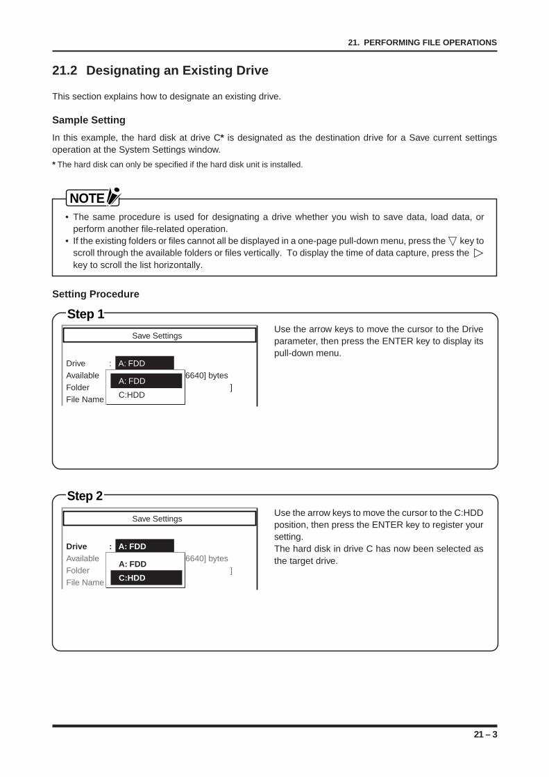
21 – 3
21. PERFORMING FILE OPERATIONS
Step 1
Step 2
21.2 Designating an Existing Drive
This section explains how to designate an existing drive.
Sample Setting
In this example, the hard disk at drive C* is designated as the destination drive for a Save current settingsoperation at the System Settings window.
* The hard disk can only be specified if the hard disk unit is installed.
NOTE• The same procedure is used for designating a drive whether you wish to save data, load data, or
perform another file-related operation.• If the existing folders or files cannot all be displayed in a one-page pull-down menu, press the key to
scroll through the available folders or files vertically. To display the time of data capture, press the key to scroll the list horizontally.
Setting Procedure
Use the arrow keys to move the cursor to the C:HDDposition, then press the ENTER key to register yoursetting.The hard disk in drive C has now been selected asthe target drive.
Use the arrow keys to move the cursor to the Driveparameter, then press the ENTER key to display itspull-down menu.
Save Settings
Drive : A: FDDAvailable : [ 1456640] bytesFolder : [\ ]File Name : DEFAULT.CND
A: FDD
C:HDD
Save Settings
Drive : A: FDDAvailable : [ 1456640] bytesFolder : [\ ]File Name : DEFAULT.CND
A: FDD
C:HDD
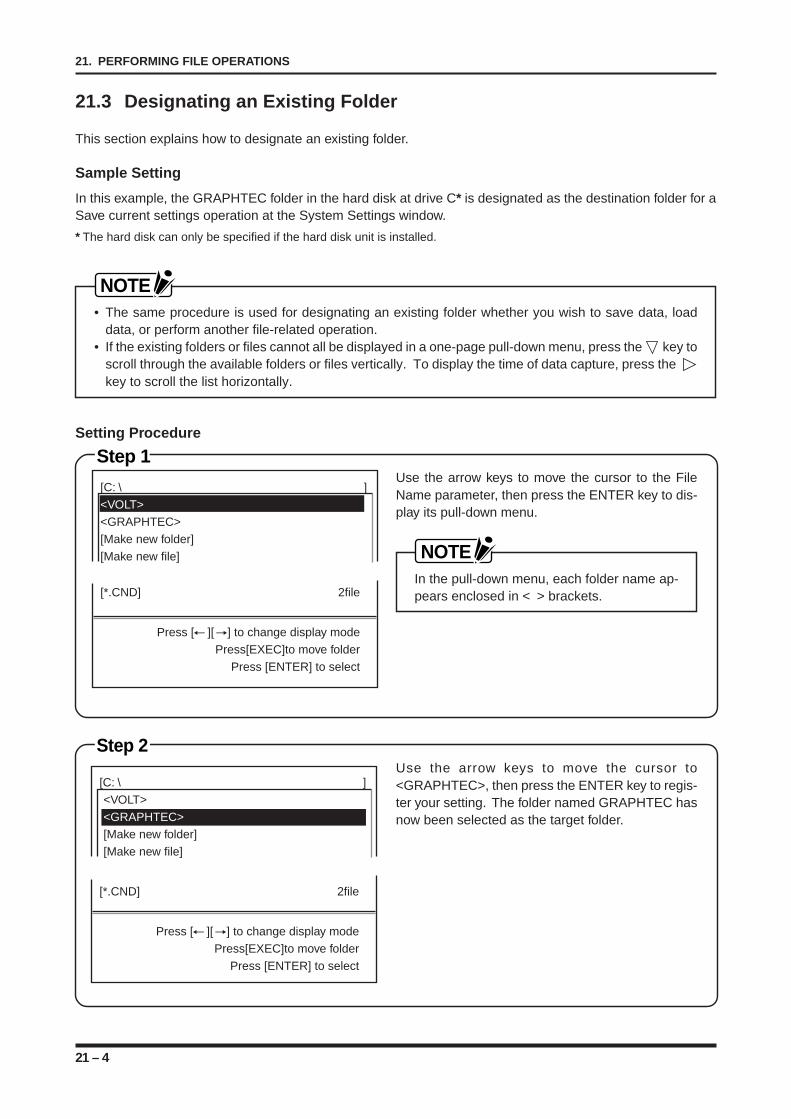
21 – 4
21. PERFORMING FILE OPERATIONS
21.3 Designating an Existing Folder
This section explains how to designate an existing folder.
Sample Setting
In this example, the GRAPHTEC folder in the hard disk at drive C* is designated as the destination folder for aSave current settings operation at the System Settings window.
* The hard disk can only be specified if the hard disk unit is installed.
NOTE• The same procedure is used for designating an existing folder whether you wish to save data, load
data, or perform another file-related operation.• If the existing folders or files cannot all be displayed in a one-page pull-down menu, press the key to
scroll through the available folders or files vertically. To display the time of data capture, press the key to scroll the list horizontally.
Setting Procedure
Step 1
Step 2Use the arrow keys to move the cursor to<GRAPHTEC>, then press the ENTER key to regis-ter your setting. The folder named GRAPHTEC hasnow been selected as the target folder.
Use the arrow keys to move the cursor to the FileName parameter, then press the ENTER key to dis-play its pull-down menu.
NOTEIn the pull-down menu, each folder name ap-pears enclosed in < > brackets.
[C: \ ]<VOLT><GRAPHTEC>[Make new folder][Make new file]
[*.CND] 2file
Press [ ][ ] to change display modePress[EXEC]to move folder
Press [ENTER] to select
[C: \ ]<VOLT><GRAPHTEC>[Make new folder][Make new file]
[*.CND] 2file
Press [ ][ ] to change display modePress[EXEC]to move folder
Press [ENTER] to select
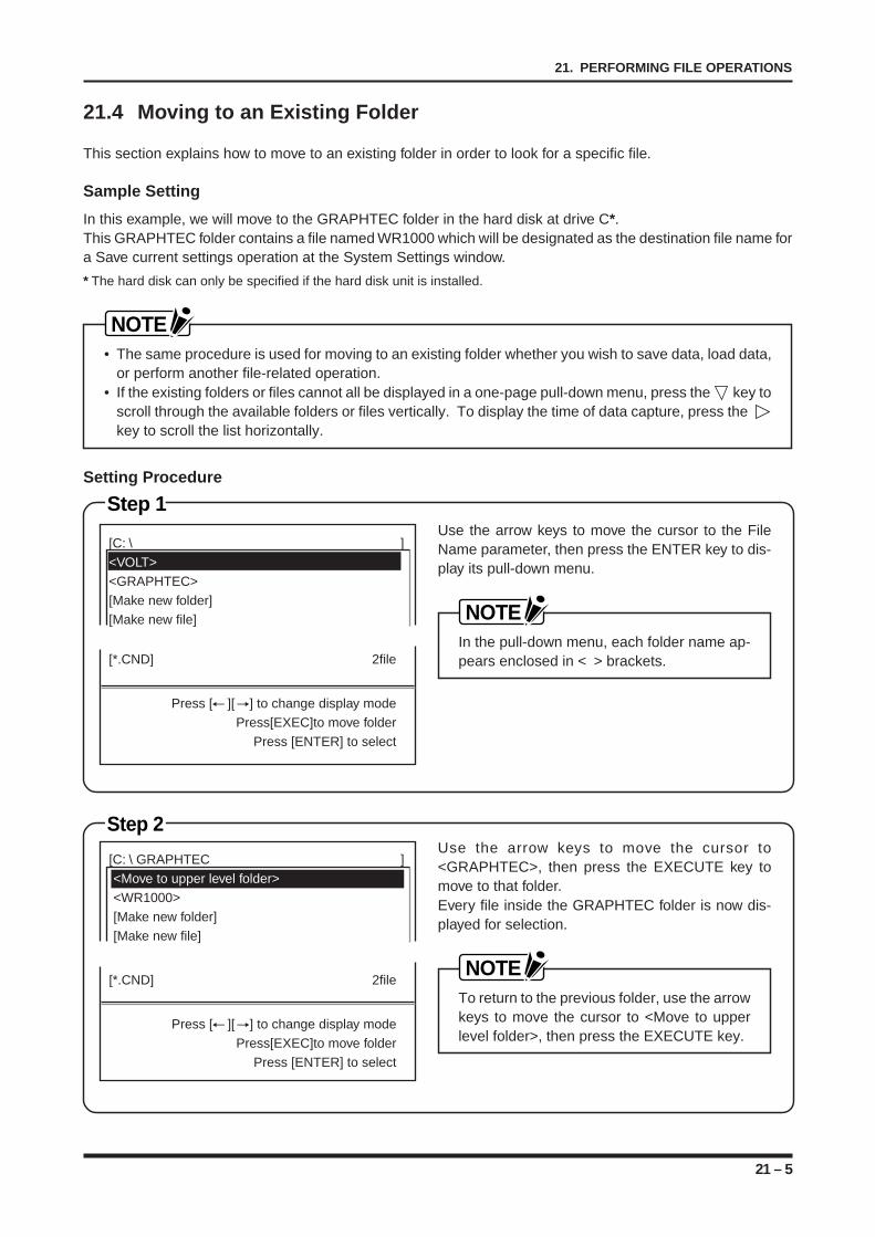
21 – 5
21. PERFORMING FILE OPERATIONS
21.4 Moving to an Existing Folder
This section explains how to move to an existing folder in order to look for a specific file.
Sample Setting
In this example, we will move to the GRAPHTEC folder in the hard disk at drive C*.This GRAPHTEC folder contains a file named WR1000 which will be designated as the destination file name fora Save current settings operation at the System Settings window.
* The hard disk can only be specified if the hard disk unit is installed.
NOTE• The same procedure is used for moving to an existing folder whether you wish to save data, load data,
or perform another file-related operation.• If the existing folders or files cannot all be displayed in a one-page pull-down menu, press the key to
scroll through the available folders or files vertically. To display the time of data capture, press the key to scroll the list horizontally.
Setting Procedure
Step 1
Step 2
Use the arrow keys to move the cursor to the FileName parameter, then press the ENTER key to dis-play its pull-down menu.
NOTEIn the pull-down menu, each folder name ap-pears enclosed in < > brackets.
Use the arrow keys to move the cursor to<GRAPHTEC>, then press the EXECUTE key tomove to that folder.Every file inside the GRAPHTEC folder is now dis-played for selection.
NOTETo return to the previous folder, use the arrowkeys to move the cursor to <Move to upperlevel folder>, then press the EXECUTE key.
[C: \ GRAPHTEC ]<Move to upper level folder><WR1000>[Make new folder][Make new file]
[*.CND] 2file
Press [ ][ ] to change display modePress[EXEC]to move folder
Press [ENTER] to select
[C: \ ]<VOLT><GRAPHTEC>[Make new folder][Make new file]
[*.CND] 2file
Press [ ][ ] to change display modePress[EXEC]to move folder
Press [ENTER] to select
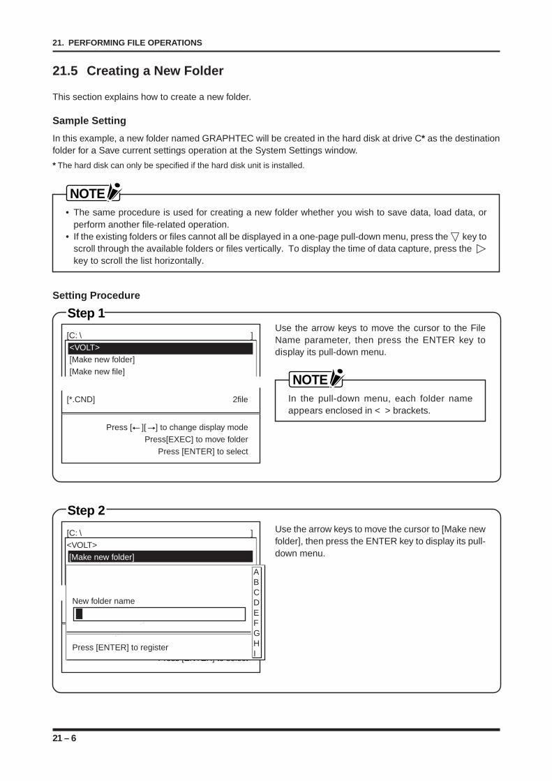
21 – 6
21. PERFORMING FILE OPERATIONS
21.5 Creating a New Folder
This section explains how to create a new folder.
Sample Setting
In this example, a new folder named GRAPHTEC will be created in the hard disk at drive C* as the destinationfolder for a Save current settings operation at the System Settings window.
* The hard disk can only be specified if the hard disk unit is installed.
NOTE• The same procedure is used for creating a new folder whether you wish to save data, load data, or
perform another file-related operation.• If the existing folders or files cannot all be displayed in a one-page pull-down menu, press the key to
scroll through the available folders or files vertically. To display the time of data capture, press the key to scroll the list horizontally.
Setting Procedure
Step 2Use the arrow keys to move the cursor to [Make newfolder], then press the ENTER key to display its pull-down menu.
[C: \ ]<VOLT> [Make new folder][Make new file]
[*.CND] 1file
Press [ ][ ] to change display modePress[EXEC]to move folder
Press [ENTER] to select
New folder name
Press [ENTER] to register
ABCDEFGHI
Step 1Use the arrow keys to move the cursor to the FileName parameter, then press the ENTER key todisplay its pull-down menu.
NOTEIn the pull-down menu, each folder nameappears enclosed in < > brackets.
[C: \ ]<VOLT>[Make new folder][Make new file]
[*.CND] 2file
Press [ ][ ] to change display modePress[EXEC] to move folder
Press [ENTER] to select
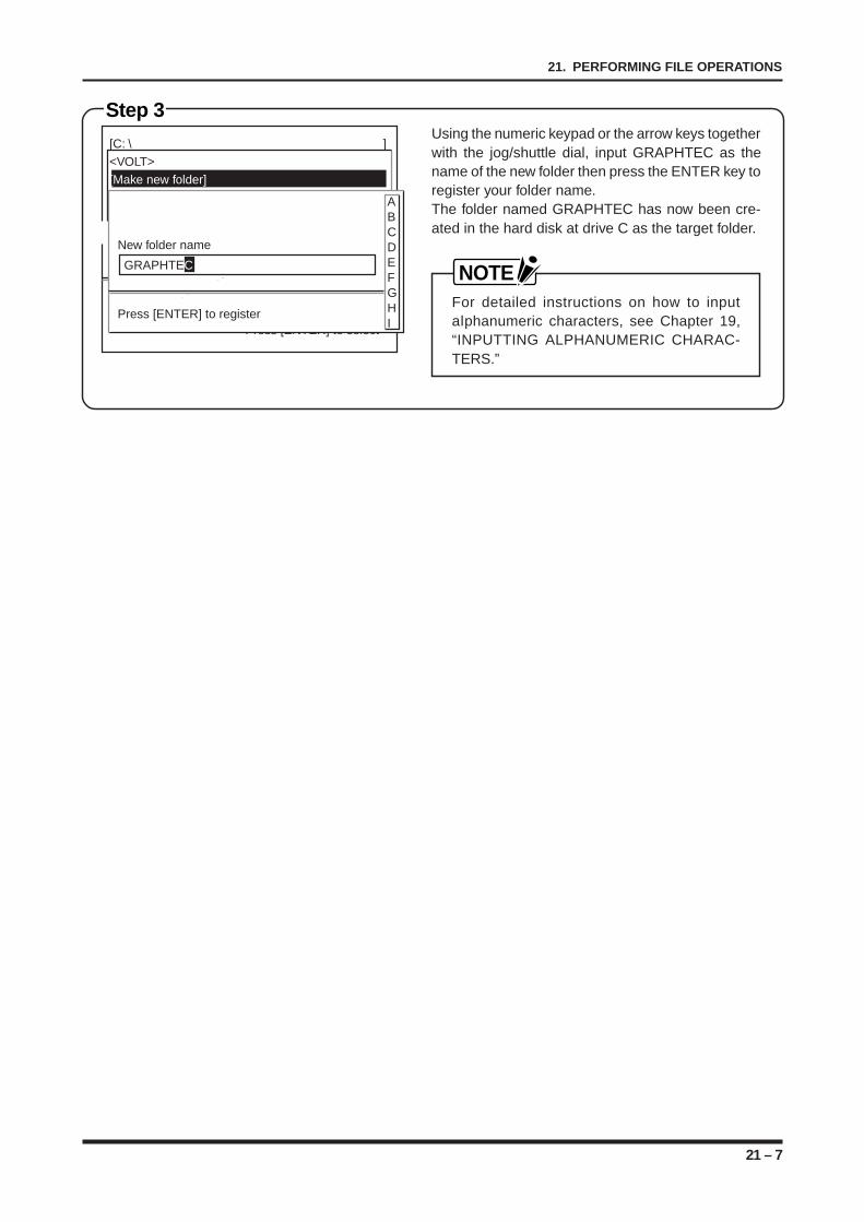
21 – 7
21. PERFORMING FILE OPERATIONS
Step 3Using the numeric keypad or the arrow keys togetherwith the jog/shuttle dial, input GRAPHTEC as thename of the new folder then press the ENTER key toregister your folder name.The folder named GRAPHTEC has now been cre-ated in the hard disk at drive C as the target folder.
NOTEFor detailed instructions on how to inputalphanumeric characters, see Chapter 19,“INPUTTING ALPHANUMERIC CHARAC-TERS.”
[C: \ ]<VOLT>[Make new folder][Make new file]
[*.CND] 1file
Press [ ][ ] to change display modePress[EXEC]to move folder
Press [ENTER] to select
New folder name
Press [ENTER] to register
ABCDEFGHI
GRAPHTEC
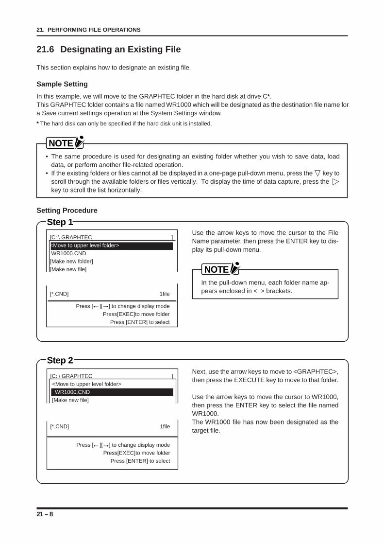
21 – 8
21. PERFORMING FILE OPERATIONS
21.6 Designating an Existing File
This section explains how to designate an existing file.
Sample Setting
In this example, we will move to the GRAPHTEC folder in the hard disk at drive C*.This GRAPHTEC folder contains a file named WR1000 which will be designated as the destination file name fora Save current settings operation at the System Settings window.
* The hard disk can only be specified if the hard disk unit is installed.
NOTE• The same procedure is used for designating an existing folder whether you wish to save data, load
data, or perform another file-related operation.• If the existing folders or files cannot all be displayed in a one-page pull-down menu, press the key to
scroll through the available folders or files vertically. To display the time of data capture, press the key to scroll the list horizontally.
Setting Procedure
Step 1Use the arrow keys to move the cursor to the FileName parameter, then press the ENTER key to dis-play its pull-down menu.
NOTEIn the pull-down menu, each folder name ap-pears enclosed in < > brackets.
[C: \ GRAPHTEC ]<Move to upper level folder> WR1000.CND[Make new folder][Make new file]
[*.CND] 1file
Press [ ][ ] to change display modePress[EXEC]to move folder
Press [ENTER] to select
Step 2Next, use the arrow keys to move to <GRAPHTEC>,then press the EXECUTE key to move to that folder.
Use the arrow keys to move the cursor to WR1000,then press the ENTER key to select the file namedWR1000.The WR1000 file has now been designated as thetarget file.
[C: \ GRAPHTEC ]<Move to upper level folder> WR1000.CND[Make new file]
[*.CND] 1file
Press [ ][ ] to change display modePress[EXEC]to move folder
Press [ENTER] to select
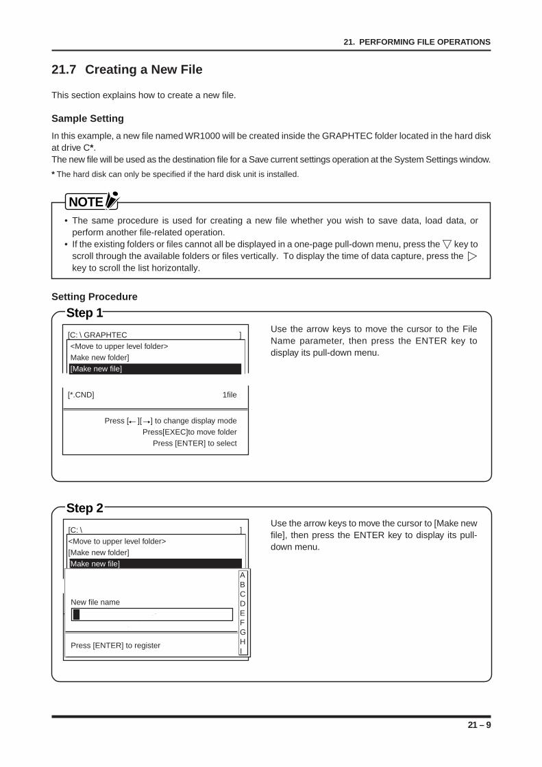
21 – 9
21. PERFORMING FILE OPERATIONS
21.7 Creating a New File
This section explains how to create a new file.
Sample Setting
In this example, a new file named WR1000 will be created inside the GRAPHTEC folder located in the hard diskat drive C*.The new file will be used as the destination file for a Save current settings operation at the System Settings window.
* The hard disk can only be specified if the hard disk unit is installed.
NOTE• The same procedure is used for creating a new file whether you wish to save data, load data, or
perform another file-related operation.• If the existing folders or files cannot all be displayed in a one-page pull-down menu, press the key to
scroll through the available folders or files vertically. To display the time of data capture, press the key to scroll the list horizontally.
Setting Procedure
Step 1Use the arrow keys to move the cursor to the FileName parameter, then press the ENTER key todisplay its pull-down menu.
[C: \ GRAPHTEC ]<Move to upper level folder>Make new folder][Make new file]
[*.CND] 1file
Press [ ][ ] to change display modePress[EXEC]to move folder
Press [ENTER] to select
Step 2Use the arrow keys to move the cursor to [Make newfile], then press the ENTER key to display its pull-down menu.
[C: \ ]<Move to upper level folder>[Make new folder][Make new file]
[*.CND] 1file
Press [ ][ ] to change display modePress[EXEC]to move folder
Press [ENTER] to select
New file name
Press [ENTER] to register
ABCDEFGHI
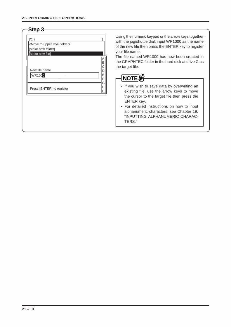
21 – 10
21. PERFORMING FILE OPERATIONS
Step 3Using the numeric keypad or the arrow keys togetherwith the jog/shuttle dial, input WR1000 as the nameof the new file then press the ENTER key to registeryour file name.The file named WR1000 has now been created inthe GRAPHTEC folder in the hard disk at drive C asthe target file.
NOTE• If you wish to save data by overwriting an
existing file, use the arrow keys to movethe cursor to the target file then press theENTER key.
• For detailed instructions on how to inputalphanumeric characters, see Chapter 19,“INPUTTING ALPHANUMERIC CHARAC-TERS.”
[C: \ ]<Move to upper level folder>[Make new folder][Make new file]
[*.CND] 1file
Press [ ][ ] to change display modePress[EXEC]to move folder
Press [ENTER] to select
New file name
Press [ENTER] to register
ABCDEFGHI
WR1000
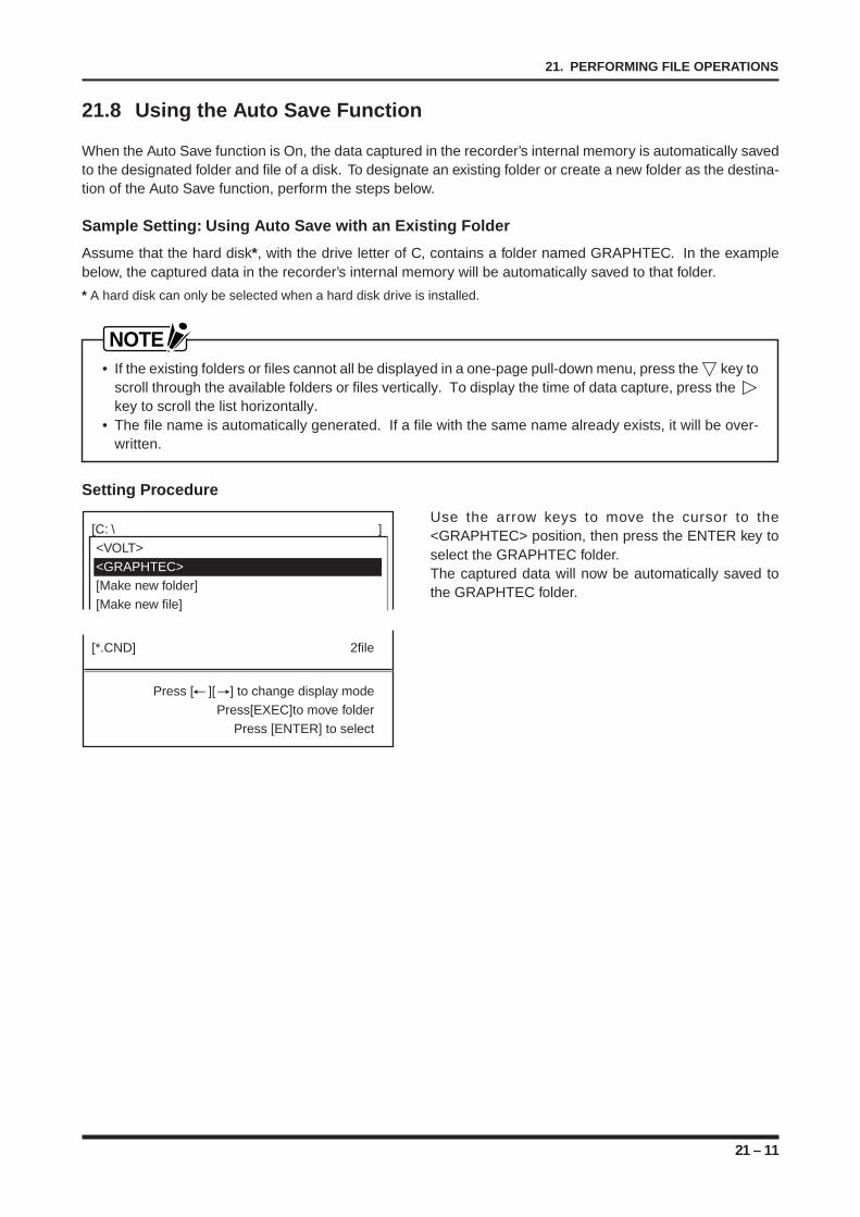
21 – 11
21. PERFORMING FILE OPERATIONS
21.8 Using the Auto Save Function
When the Auto Save function is On, the data captured in the recorder’s internal memory is automatically savedto the designated folder and file of a disk. To designate an existing folder or create a new folder as the destina-tion of the Auto Save function, perform the steps below.
Sample Setting: Using Auto Save with an Existing Folder
Assume that the hard disk*, with the drive letter of C, contains a folder named GRAPHTEC. In the examplebelow, the captured data in the recorder’s internal memory will be automatically saved to that folder.
* A hard disk can only be selected when a hard disk drive is installed.
NOTE• If the existing folders or files cannot all be displayed in a one-page pull-down menu, press the key to
scroll through the available folders or files vertically. To display the time of data capture, press the key to scroll the list horizontally.
• The file name is automatically generated. If a file with the same name already exists, it will be over-written.
Setting Procedure
Use the arrow keys to move the cursor to the<GRAPHTEC> position, then press the ENTER key toselect the GRAPHTEC folder.The captured data will now be automatically saved tothe GRAPHTEC folder.
[C: \ ]<VOLT><GRAPHTEC>[Make new folder][Make new file]
[*.CND] 2file
Press [ ][ ] to change display modePress[EXEC]to move folder
Press [ENTER] to select
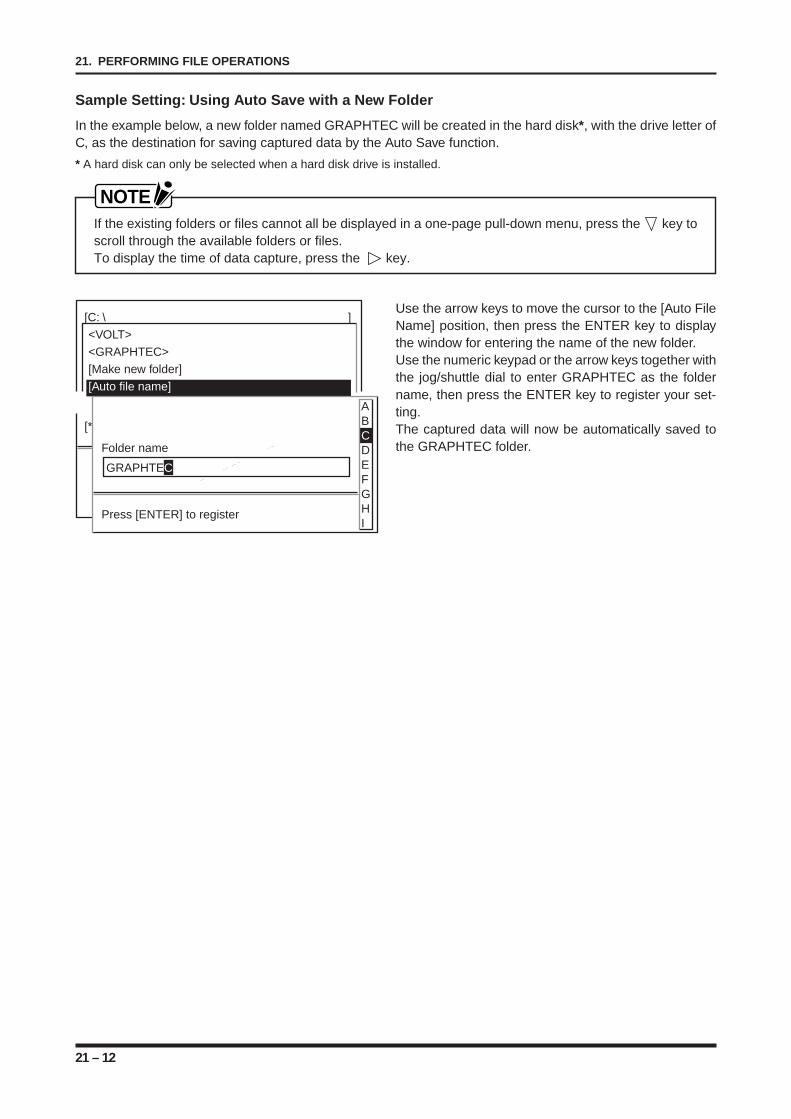
21 – 12
21. PERFORMING FILE OPERATIONS
Sample Setting: Using Auto Save with a New Folder
In the example below, a new folder named GRAPHTEC will be created in the hard disk*, with the drive letter ofC, as the destination for saving captured data by the Auto Save function.
* A hard disk can only be selected when a hard disk drive is installed.
NOTEIf the existing folders or files cannot all be displayed in a one-page pull-down menu, press the key toscroll through the available folders or files.To display the time of data capture, press the key.
Use the arrow keys to move the cursor to the [Auto FileName] position, then press the ENTER key to displaythe window for entering the name of the new folder.Use the numeric keypad or the arrow keys together withthe jog/shuttle dial to enter GRAPHTEC as the foldername, then press the ENTER key to register your set-ting.The captured data will now be automatically saved tothe GRAPHTEC folder.
[C: \ ]<VOLT><GRAPHTEC>[Make new folder][Auto file name]
[*.CND] 1file
Press [ ][ ] to change display modePress[EXEC]to move folder
Press [ENTER] to select
Folder name
Press [ENTER] to register
ABCDEFGHI
GRAPHTEC
22 – 1
22. USING THE REMOTE CONNECTOR
USING THE REMOTE CONNECTOR
This chapter provides instructions on how to use the RE-MOTE connector.
22.1 The REMOTE Connector’s Functions and PinAssignment
22.2 Assembling the REMOTE Connector22.3 Using the REMOTE Functions
CHAPTER 22CHAPTER 22
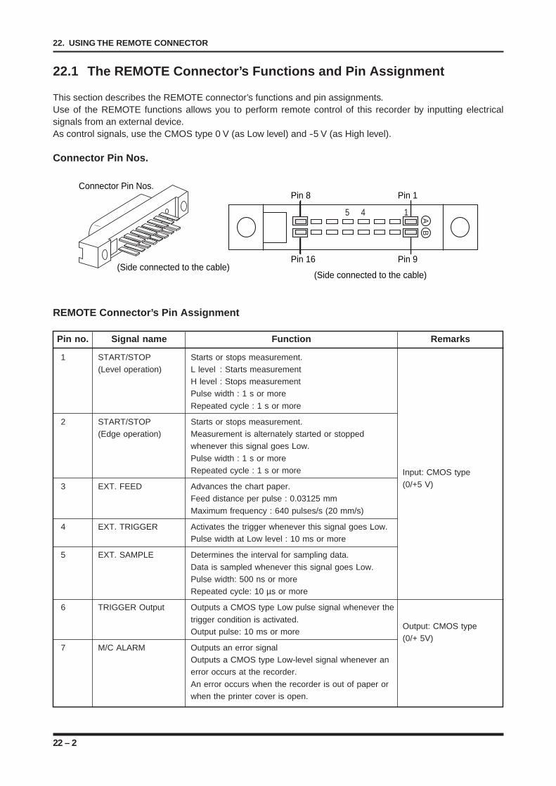
22 – 2
22. USING THE REMOTE CONNECTOR
22.1 The REMOTE Connector’s Functions and Pin Assignment
This section describes the REMOTE connector’s functions and pin assignments.Use of the REMOTE functions allows you to perform remote control of this recorder by inputting electricalsignals from an external device.As control signals, use the CMOS type 0 V (as Low level) and -5 V (as High level).
Connector Pin Nos.
Pin 8 Pin 1
Pin 16 Pin 9
5 4 1 AB
(Side connected to the cable)(Side connected to the cable)
Connector Pin Nos.
REMOTE Connector’s Pin Assignment
Pin no. Signal name Function Remarks
1 START/STOP Starts or stops measurement.(Level operation) L level : Starts measurement
H level : Stops measurementPulse width : 1 s or more
Repeated cycle : 1 s or more
2 START/STOP Starts or stops measurement.(Edge operation) Measurement is alternately started or stopped
whenever this signal goes Low.
Pulse width : 1 s or moreRepeated cycle : 1 s or more Input: CMOS type
3 EXT. FEED Advances the chart paper. (0/+5 V)
Feed distance per pulse : 0.03125 mm
Maximum frequency : 640 pulses/s (20 mm/s)
4 EXT. TRIGGER Activates the trigger whenever this signal goes Low.Pulse width at Low level : 10 ms or more
5 EXT. SAMPLE Determines the interval for sampling data.
Data is sampled whenever this signal goes Low.Pulse width: 500 ns or moreRepeated cycle: 10 µs or more
6 TRIGGER Output Outputs a CMOS type Low pulse signal whenever the
trigger condition is activated.Output: CMOS type
Output pulse: 10 ms or more(0/+ 5V)
7 M/C ALARM Outputs an error signalOutputs a CMOS type Low-level signal whenever anerror occurs at the recorder.
An error occurs when the recorder is out of paper orwhen the printer cover is open.
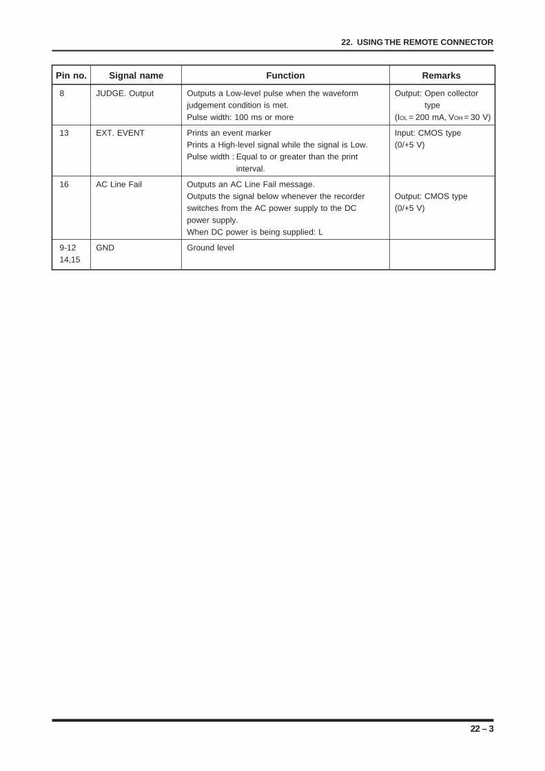
22 – 3
22. USING THE REMOTE CONNECTOR
Pin no. Signal name Function Remarks
8 JUDGE. Output Outputs a Low-level pulse when the waveform Output: Open collectorjudgement condition is met. type
Pulse width: 100 ms or more (IOL = 200 mA, VOH = 30 V)
13 EXT. EVENT Prints an event marker Input: CMOS typePrints a High-level signal while the signal is Low. (0/+5 V)Pulse width : Equal to or greater than the print
interval.
16 AC Line Fail Outputs an AC Line Fail message.Outputs the signal below whenever the recorder Output: CMOS typeswitches from the AC power supply to the DC (0/+5 V)
power supply.When DC power is being supplied: L
9-12 GND Ground level14,15
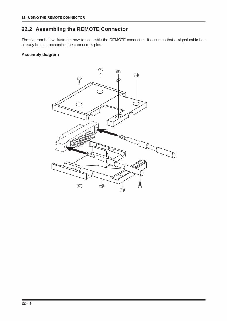
22 – 4
22. USING THE REMOTE CONNECTOR
22.2 Assembling the REMOTE Connector
The diagram below illustrates how to assemble the REMOTE connector. It assumes that a signal cable hasalready been connected to the connector’s pins.
Assembly diagram
22 – 5
22. USING THE REMOTE CONNECTOR
22.3 Using the REMOTE Functions
The following describes the procedures for using the REMOTE functions.
START/STOP
This recorder can be started or stopped from an external device by inputting the designated signal to therecorder via the REMOTE connector.
EXT. FEED
When the CHART SPEED setting in the Record menu’s RECORD SETTINGS window is EXTERNAL, inputthe designated signal via the REMOTE interface in order to feed the chart paper at a speed based on suchsignal input.
EXT. TRIGGER
When the SOURCE setting in the Trigger menu’s TRIGGER SETTINGS window is EXTERNAL, input thedesignated signal via the REMOTE connector in order to satisfy the trigger condition.
EXT. SAMPLE
When the SAMPLING INTERVAL setting in the Memory menu’s MEMORY SETTINGS window is EXTER-NAL, input the designated signal via the REMOTE connector to sample data at a sampling interval based onsuch signal input.
TRIGGER Output
When the trigger condition is satisfied, this function outputs the designated signal via the REMOTE connec-tor.
M/C ALARM
When an error occurs in one of the recorder’s functions, this function outputs the designated signal via theREMOTE connector.
JUDGE. Output
Inputs the designated signal via the REMOTE connector when the waveform judgement condition is met.
EXT. EVENT
Input the designated signal via the REMOTE connector in order to print event markers based on such signalinput.
AC Line Fail
This function is only available when the DC adapter unit is installed. If a power failure or other problem forcesthe recorder to switch from the AC power supply to the DC power supply, this function outputs the designatedsignal via the REMOTE connector.

22 – 6
22. USING THE REMOTE CONNECTOR
A – 1
APPENDIX A. SPECIFICATIONS
SPECIFICATIONS
This appendix provides the WR1000’s specifications.
A.1 Basic SpecificationsA.2 Memory FunctionsA.3 Trigger FunctionsA.4 Measured Mode FunctionA.5 Plug-in Amplifiers FunctionsA.5.1 V (Voltage Input) Type AmpA.5.2 M (Multi-Input) Type AmpA.5.3 LO (Logic) Type AmpA.6 Memory DevicesA.6.1 Floppy Disk DriveA.6.2 MO (Magneto-Optic) Disk Drive (Factory-Installed
Option)A.6.3 Hard Disk (Factory-Installed Option)A.7 Interface UnitsA.7.1 RS-232C InterfaceA.7.2 GB-IB InterfaceA.7.3 SCSI Interface Unit (Factory-Installed Unit)A.8 DC Adapter Unit (Factory-Installed Option)
APPENDIX AAPPENDIX A
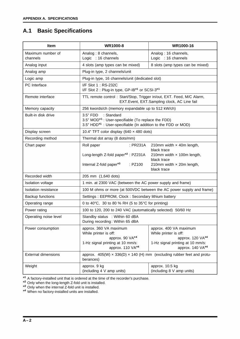
A – 2
APPENDIX A. SPECIFICATIONS
A.1 Basic Specifications
Item WR1000-8 WR1000-16
Maximum number of Analog : 8 channels, Analog : 16 channels,channels Logic : 16 channels Logic : 16 channels
Analog input 4 slots (amp types can be mixed) 8 slots (amp types can be mixed)
Analog amp Plug-in type, 2 channels/unit
Logic amp Plug-in type, 16 channels/unit (dedicated slot)
PC Interface I/F Slot 1 : RS-232CI/F Slot 2 : Plug-in type, GP-IB*1 or SCSI-3*1
Remote interface TTL remote control : Start/Stop, Trigger in/out, EXT. Feed, M/C Alarm,EXT.Event, EXT.Sampling clock, AC Line fail
Memory capacity 256 kwords/ch (memory expandable up to 512 kW/ch)
Built-in disk drive 3.5” FDD : Standard3.5” MOD*1 : User-specifiable (To replace the FDD)3.5” HDD*1 : User-specifiable (In addition to the FDD or MOD)
Display screen 10.4” TFT color display (640 × 480 dots)
Recording method Thermal dot array (8 dots/mm)
Chart paper Roll paper : PR231A 210mm width × 40m length,black trace
Long-length Z-fold paper*2 : PZ231A 210mm width × 100m length,black trace
Internal Z-fold paper*3 : PZ100 210mm width × 20m length,black trace
Recorded width 205 mm (1,640 dots)
Isolation voltage 1 min. at 2300 VAC (between the AC power supply and frame)
Isolation resistance 100 M ohms or more (at 500VDC between the AC power supply and frame)
Backup functions Settings : EEPROM, Clock : Secondary lithium battery
Operating range 0 to 40°C, 30 to 80 % RH (5 to 35°C for printing)
Power rating 100 to 120, 200 to 240 VAC (automatically selected) 50/60 Hz
Operating noise level Standby status : Within 60 dBADuring recording : Within 65 dBA
Power consumption approx. 360 VA maximum approx. 400 VA maximumWhile printer is off: While printer is off:
approx. 90 VA*4 approx. 120 VA*4
1-Hz signal printing at 10 mm/s: 1-Hz signal printing at 10 mm/s:approx. 110 VA*4 approx. 140 VA*4
External dimensions approx. 405(W) × 336(D) × 140 (H) mm (excluding rubber feet and protu-berances)
Weight approx. 9 kg approx. 10.5 kg(including 4 V amp units) (including 8 V amp units)
*1 A factory-installed unit that is ordered at the time of the recorder’s purchase.*2 Only when the long-length Z-fold unit is installed.*3 Only when the internal Z-fold unit is installed.*4 When no factory-installed units are installed.
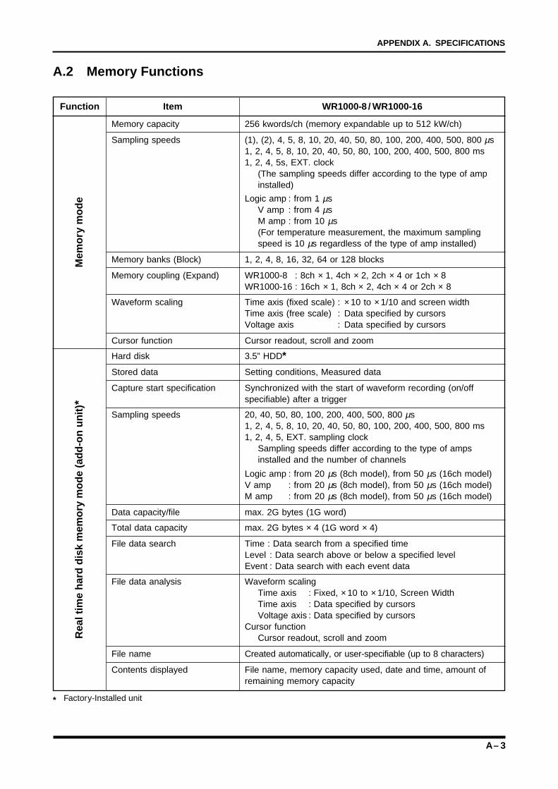
A – 3
APPENDIX A. SPECIFICATIONS
A.2 Memory Functions
Function Item WR1000-8 / WR1000-16
Memory capacity 256 kwords/ch (memory expandable up to 512 kW/ch)
Sampling speeds (1), (2), 4, 5, 8, 10, 20, 40, 50, 80, 100, 200, 400, 500, 800 µs1, 2, 4, 5, 8, 10, 20, 40, 50, 80, 100, 200, 400, 500, 800 ms1, 2, 4, 5s, EXT. clock
(The sampling speeds differ according to the type of ampinstalled)
Logic amp : from 1 µsV amp : from 4 µsM amp : from 10 µs(For temperature measurement, the maximum samplingspeed is 10 µs regardless of the type of amp installed)
Memory banks (Block) 1, 2, 4, 8, 16, 32, 64 or 128 blocks
Memory coupling (Expand) WR1000-8 : 8ch × 1, 4ch × 2, 2ch × 4 or 1ch × 8WR1000-16 : 16ch × 1, 8ch × 2, 4ch × 4 or 2ch × 8
Waveform scaling Time axis (fixed scale) : × 10 to × 1/10 and screen widthTime axis (free scale) : Data specified by cursorsVoltage axis : Data specified by cursors
Cursor function Cursor readout, scroll and zoom
Hard disk 3.5” HDD*
Stored data Setting conditions, Measured data
Capture start specification Synchronized with the start of waveform recording (on/offspecifiable) after a trigger
Sampling speeds 20, 40, 50, 80, 100, 200, 400, 500, 800 µs1, 2, 4, 5, 8, 10, 20, 40, 50, 80, 100, 200, 400, 500, 800 ms1, 2, 4, 5, EXT. sampling clock
Sampling speeds differ according to the type of ampsinstalled and the number of channels
Logic amp : from 20 µs (8ch model), from 50 µs (16ch model)V amp : from 20 µs (8ch model), from 50 µs (16ch model)M amp : from 20 µs (8ch model), from 50 µs (16ch model)
Data capacity/file max. 2G bytes (1G word)
Total data capacity max. 2G bytes × 4 (1G word × 4)
File data search Time : Data search from a specified timeLevel : Data search above or below a specified levelEvent : Data search with each event data
File data analysis Waveform scalingTime axis : Fixed, × 10 to × 1/10, Screen WidthTime axis : Data specified by cursorsVoltage axis : Data specified by cursors
Cursor functionCursor readout, scroll and zoom
File name Created automatically, or user-specifiable (up to 8 characters)
Contents displayed File name, memory capacity used, date and time, amount ofremaining memory capacity
* Factory-Installed unit
Mem
ory
mo
de
Rea
l tim
e h
ard
dis
k m
emo
ry m
od
e (a
dd
-on
un
it) *
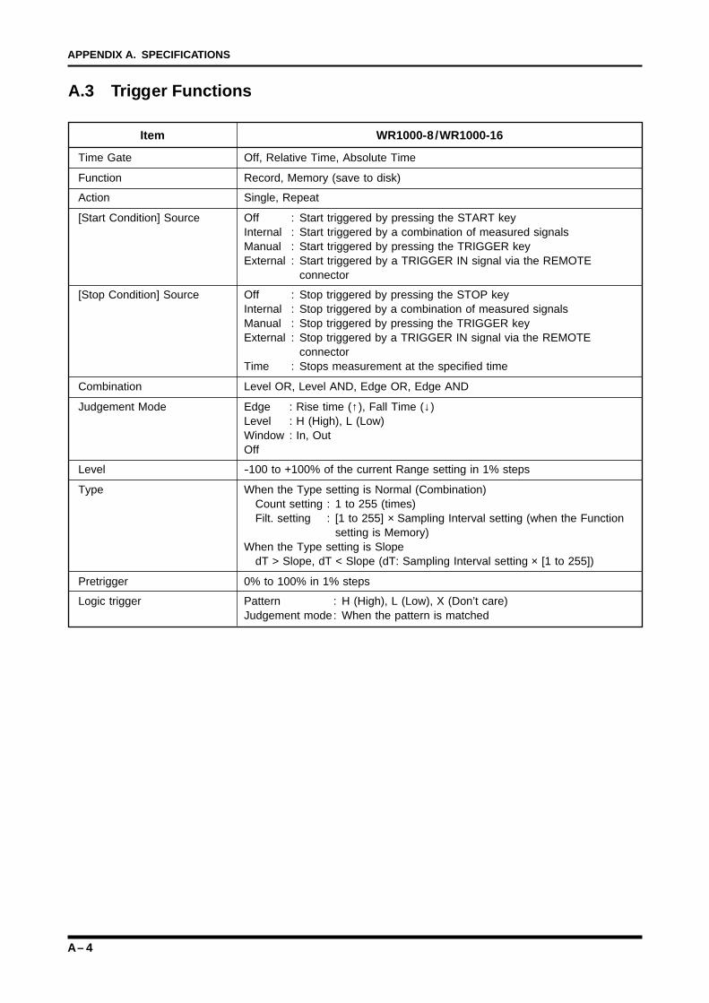
A – 4
APPENDIX A. SPECIFICATIONS
A.3 Trigger Functions
Item WR1000-8 /WR1000-16
Time Gate Off, Relative Time, Absolute Time
Function Record, Memory (save to disk)
Action Single, Repeat
[Start Condition] Source Off : Start triggered by pressing the START keyInternal : Start triggered by a combination of measured signalsManual : Start triggered by pressing the TRIGGER keyExternal : Start triggered by a TRIGGER IN signal via the REMOTE
connector
[Stop Condition] Source Off : Stop triggered by pressing the STOP keyInternal : Stop triggered by a combination of measured signalsManual : Stop triggered by pressing the TRIGGER keyExternal : Stop triggered by a TRIGGER IN signal via the REMOTE
connectorTime : Stops measurement at the specified time
Combination Level OR, Level AND, Edge OR, Edge AND
Judgement Mode Edge : Rise time (↑), Fall Time (↓)Level : H (High), L (Low)Window : In, OutOff
Level -100 to +100% of the current Range setting in 1% steps
Type When the Type setting is Normal (Combination)Count setting : 1 to 255 (times)Filt. setting : [1 to 255] × Sampling Interval setting (when the Function
setting is Memory)When the Type setting is Slope
dT > Slope, dT < Slope (dT: Sampling Interval setting × [1 to 255])
Pretrigger 0% to 100% in 1% steps
Logic trigger Pattern : H (High), L (Low), X (Don’t care)Judgement mode: When the pattern is matched
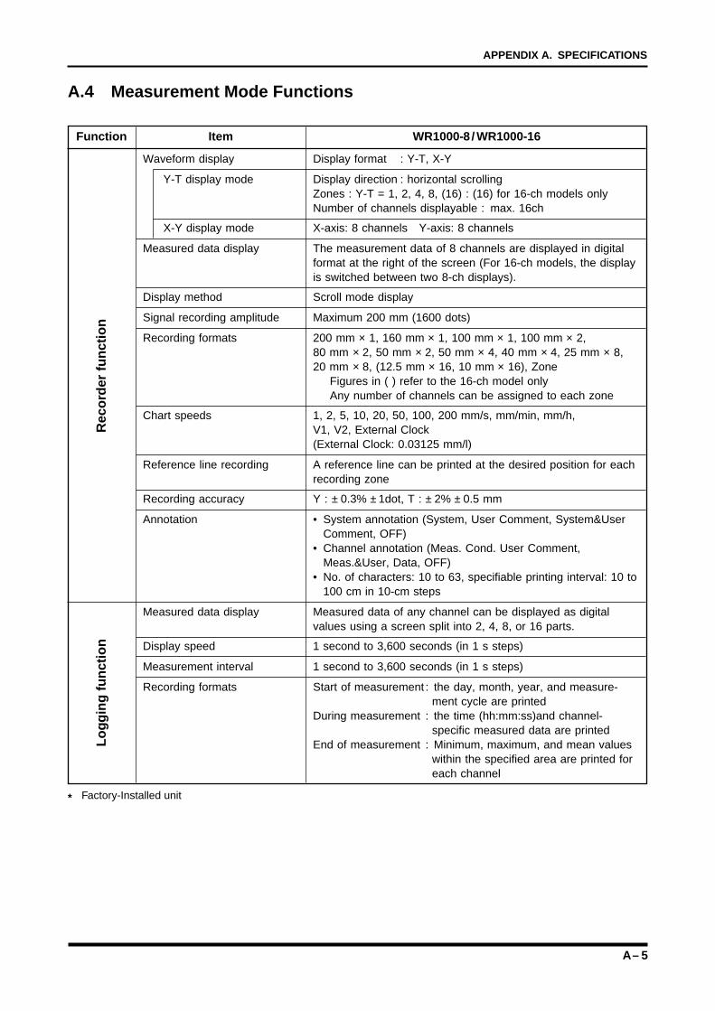
A – 5
APPENDIX A. SPECIFICATIONS
A.4 Measurement Mode Functions
Function Item WR1000-8 / WR1000-16
Waveform display Display format : Y-T, X-Y
Y-T display mode Display direction : horizontal scrollingZones : Y-T = 1, 2, 4, 8, (16) : (16) for 16-ch models onlyNumber of channels displayable : max. 16ch
X-Y display mode X-axis: 8 channels Y-axis: 8 channels
Measured data display The measurement data of 8 channels are displayed in digitalformat at the right of the screen (For 16-ch models, the displayis switched between two 8-ch displays).
Display method Scroll mode display
Signal recording amplitude Maximum 200 mm (1600 dots)
Recording formats 200 mm × 1, 160 mm × 1, 100 mm × 1, 100 mm × 2,80 mm × 2, 50 mm × 2, 50 mm × 4, 40 mm × 4, 25 mm × 8,20 mm × 8, (12.5 mm × 16, 10 mm × 16), Zone
Figures in ( ) refer to the 16-ch model onlyAny number of channels can be assigned to each zone
Chart speeds 1, 2, 5, 10, 20, 50, 100, 200 mm/s, mm/min, mm/h,V1, V2, External Clock(External Clock: 0.03125 mm/l)
Reference line recording A reference line can be printed at the desired position for eachrecording zone
Recording accuracy Y : ± 0.3% ± 1dot, T : ± 2% ± 0.5 mm
Annotation • System annotation (System, User Comment, System&UserComment, OFF)
• Channel annotation (Meas. Cond. User Comment,Meas.&User, Data, OFF)
• No. of characters: 10 to 63, specifiable printing interval: 10 to100 cm in 10-cm steps
Measured data display Measured data of any channel can be displayed as digitalvalues using a screen split into 2, 4, 8, or 16 parts.
Display speed 1 second to 3,600 seconds (in 1 s steps)
Measurement interval 1 second to 3,600 seconds (in 1 s steps)
Recording formats Start of measurement : the day, month, year, and measure-ment cycle are printed
During measurement : the time (hh:mm:ss)and channel-specific measured data are printed
End of measurement : Minimum, maximum, and mean valueswithin the specified area are printed foreach channel
* Factory-Installed unit
Rec
ord
er f
un
ctio
nL
og
gin
g f
un
ctio
n
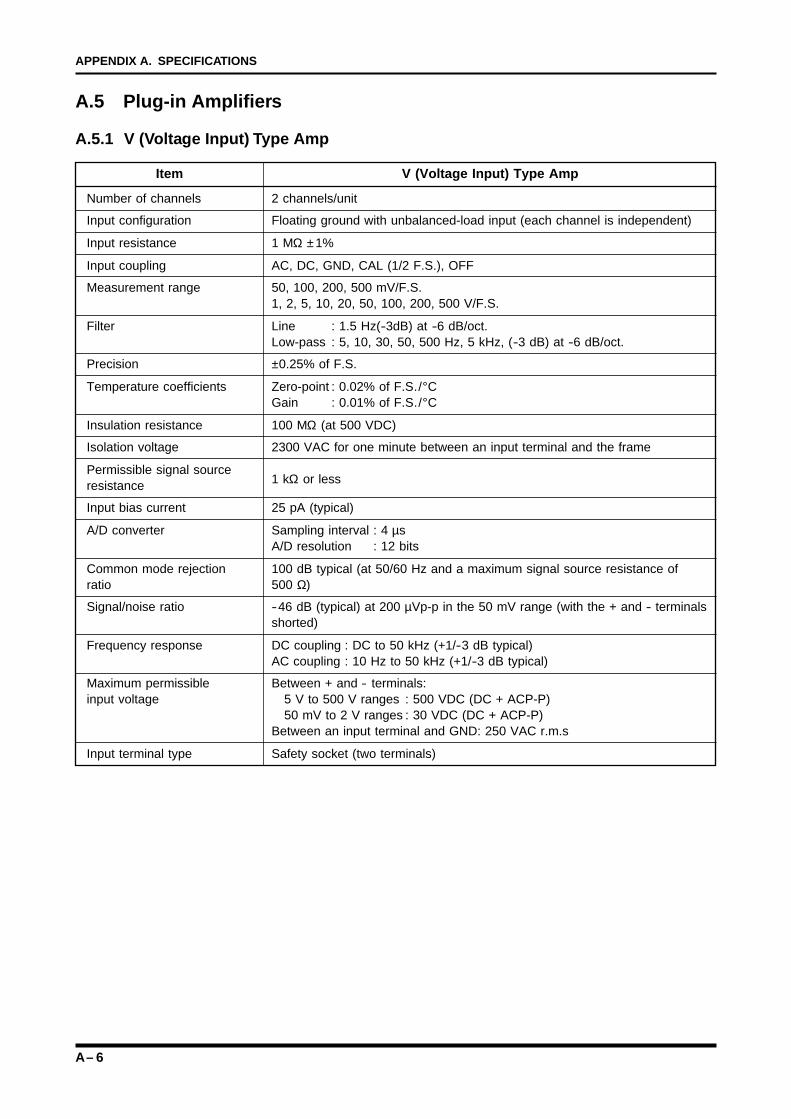
A – 6
APPENDIX A. SPECIFICATIONS
A.5 Plug-in Amplifiers
A.5.1 V (Voltage Input) Type Amp
Item V (Voltage Input) Type Amp
Number of channels 2 channels/unit
Input configuration Floating ground with unbalanced-load input (each channel is independent)
Input resistance 1 MΩ ±1%
Input coupling AC, DC, GND, CAL (1/2 F.S.), OFF
Measurement range 50, 100, 200, 500 mV/F.S.1, 2, 5, 10, 20, 50, 100, 200, 500 V/F.S.
Filter Line : 1.5 Hz(-3dB) at -6 dB/oct.Low-pass : 5, 10, 30, 50, 500 Hz, 5 kHz, (-3 dB) at -6 dB/oct.
Precision ±0.25% of F.S.
Temperature coefficients Zero-point : 0.02% of F.S./°CGain : 0.01% of F.S./°C
Insulation resistance 100 MΩ (at 500 VDC)
Isolation voltage 2300 VAC for one minute between an input terminal and the frame
Permissible signal source1 kΩ or lessresistance
Input bias current 25 pA (typical)
A/D converter Sampling interval : 4 µsA/D resolution : 12 bits
Common mode rejection 100 dB typical (at 50/60 Hz and a maximum signal source resistance ofratio 500 Ω)
Signal/noise ratio -46 dB (typical) at 200 µVp-p in the 50 mV range (with the + and - terminalsshorted)
Frequency response DC coupling : DC to 50 kHz (+1/-3 dB typical)AC coupling : 10 Hz to 50 kHz (+1/-3 dB typical)
Maximum permissible Between + and - terminals:input voltage 5 V to 500 V ranges : 500 VDC (DC + ACP-P)
50 mV to 2 V ranges : 30 VDC (DC + ACP-P)Between an input terminal and GND: 250 VAC r.m.s
Input terminal type Safety socket (two terminals)
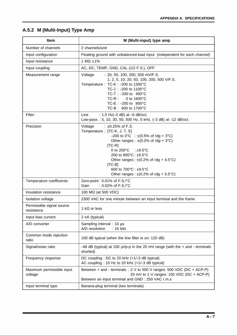
A – 7
APPENDIX A. SPECIFICATIONS
A.5.2 M (Multi-Input) Type Amp
Item M (Multi-input) type amp
Number of channels 2 channels/unit
Input configuration Floating ground with unbalanced-load input (independent for each channel)
Input resistance 1 MΩ ±1%
Input coupling AC, DC, TEMP, GND, CAL (1/2 F.S.), OFF
Measurement range Voltage : 20, 50, 100, 200, 500 mV/F.S.1, 2, 5, 10, 20, 50, 100, 200, 500 V/F.S.
Temperature : TC-K : -200 to 1300°CTC-J : -200 to 1100°CTC-T : -200 to 400°CTC-R : 0 to 1600°CTC-E : -200 to 800°CTC-B : 600 to 1700°C
Filter Line : 1.5 Hz(-3 dB) at -6 dB/oct.Low-pass : 5, 10, 30, 50, 500 Hz, 5 kHz, (-3 dB) at -12 dB/oct.
Precision Voltage : ±0.25% of F.S.Temperature : [TC-K, J, T, E]
-200 to 0°C : ±(0.5% of rdg + 3°C)Other ranges : ±(0.2% of rdg + 3°C)
[TC-R]0 to 200°C : ±9.5°C200 to 800°C : ±6.5°COther ranges : ±(0.2% of rdg + 4.5°C)
[TC-B]600 to 700°C : ±9.5°COther ranges : ±(0.2% of rdg + 5.5°C)
Temperature coefficients Zero-point : 0.01% of F.S./°CGain : 0.02% of F.S./°C
Insulation resistance 100 MΩ (at 500 VDC)
Isolation voltage 2300 VAC for one minute between an input terminal and the frame
Permissible signal source1 kΩ or lessresistance
Input bias current 2 nA (typical)
A/D converter Sampling interval : 10 µsA/D resolution : 16 bits
Common mode rejection100 dB typical (when the line filter is on: 120 dB)ratio
Signal/noise ratio -48 dB (typical) at 100 µVp-p in the 20 mV range (with the + and - terminalsshorted)
Frequency response DC coupling : DC to 20 kHz (+1/-3 dB typical)AC coupling : 10 Hz to 20 kHz (+1/-3 dB typical)
Maximum permissible input Between + and - terminals : 2 V to 500 V ranges: 500 VDC (DC + ACP-P)voltage 20 mV to 1 V ranges: 100 VDC (DC + ACP-P)
Between an input terminal and GND : 250 VAC r.m.s
Input terminal type Banana-plug terminal (two terminals)
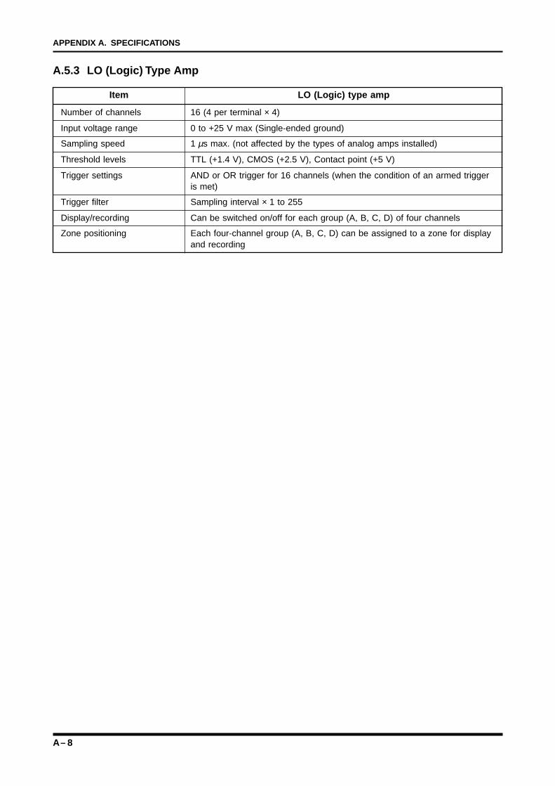
A – 8
APPENDIX A. SPECIFICATIONS
A.5.3 LO (Logic) Type Amp
Item LO (Logic) type amp
Number of channels 16 (4 per terminal × 4)
Input voltage range 0 to +25 V max (Single-ended ground)
Sampling speed 1 µs max. (not affected by the types of analog amps installed)
Threshold levels TTL (+1.4 V), CMOS (+2.5 V), Contact point (+5 V)
Trigger settings AND or OR trigger for 16 channels (when the condition of an armed triggeris met)
Trigger filter Sampling interval × 1 to 255
Display/recording Can be switched on/off for each group (A, B, C, D) of four channels
Zone positioning Each four-channel group (A, B, C, D) can be assigned to a zone for displayand recording
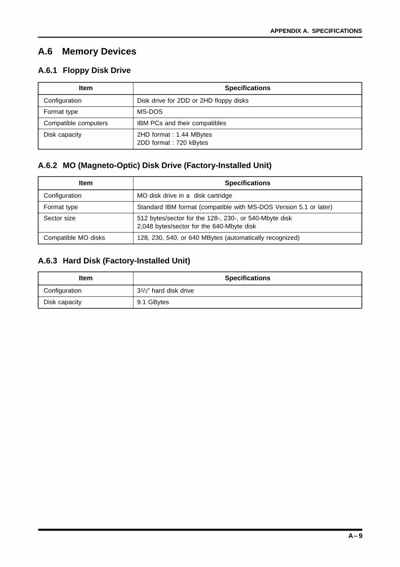
A – 9
APPENDIX A. SPECIFICATIONS
A.6 Memory Devices
A.6.1 Floppy Disk Drive
Item Specifications
Configuration Disk drive for 2DD or 2HD floppy disks
Format type MS-DOS
Compatible computers IBM PCs and their compatibles
Disk capacity 2HD format : 1.44 MBytes2DD format : 720 kBytes
A.6.2 MO (Magneto-Optic) Disk Drive (Factory-Installed Unit)
Item Specifications
Configuration MO disk drive in a disk cartridge
Format type Standard IBM format (compatible with MS-DOS Version 5.1 or later)
Sector size 512 bytes/sector for the 128-, 230-, or 540-Mbyte disk2,048 bytes/sector for the 640-Mbyte disk
Compatible MO disks 128, 230, 540, or 640 MBytes (automatically recognized)
A.6.3 Hard Disk (Factory-Installed Unit)
Item Specifications
Configuration 31/2” hard disk drive
Disk capacity 9.1 GBytes
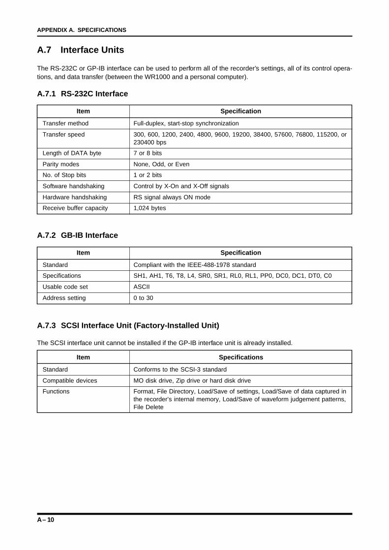
A – 10
APPENDIX A. SPECIFICATIONS
A.7 Interface Units
The RS-232C or GP-IB interface can be used to perform all of the recorder’s settings, all of its control opera-tions, and data transfer (between the WR1000 and a personal computer).
A.7.1 RS-232C Interface
Item Specification
Transfer method Full-duplex, start-stop synchronization
Transfer speed 300, 600, 1200, 2400, 4800, 9600, 19200, 38400, 57600, 76800, 115200, or230400 bps
Length of DATA byte 7 or 8 bits
Parity modes None, Odd, or Even
No. of Stop bits 1 or 2 bits
Software handshaking Control by X-On and X-Off signals
Hardware handshaking RS signal always ON mode
Receive buffer capacity 1,024 bytes
A.7.2 GB-IB Interface
Item Specification
Standard Compliant with the IEEE-488-1978 standard
Specifications SH1, AH1, T6, T8, L4, SR0, SR1, RL0, RL1, PP0, DC0, DC1, DT0, C0
Usable code set ASCII
Address setting 0 to 30
A.7.3 SCSI Interface Unit (Factory-Installed Unit)
The SCSI interface unit cannot be installed if the GP-IB interface unit is already installed.
Item Specifications
Standard Conforms to the SCSI-3 standard
Compatible devices MO disk drive, Zip drive or hard disk drive
Functions Format, File Directory, Load/Save of settings, Load/Save of data captured inthe recorder’s internal memory, Load/Save of waveform judgement patterns,File Delete
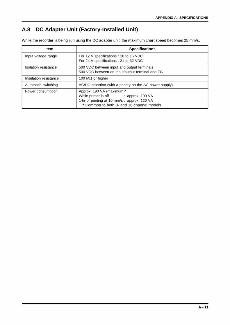
A – 11
APPENDIX A. SPECIFICATIONS
A.8 DC Adapter Unit (Factory-Installed Unit)
While the recorder is being run using the DC adapter unit, the maximum chart speed becomes 25 mm/s.
Item Specifications
Input voltage range For 12 V specifications : 10 to 16 VDCFor 24 V specifications : 21 to 32 VDC
Isolation resistance 500 VDC between input and output terminals500 VDC between an input/output terminal and FG
Insulation resistance 100 MΩ or higher
Automatic switching AC/DC selection (with a priority on the AC power supply)
Power consumption Approx. 190 VA (maximum)*While printer is off : approx. 100 VA1-hr of printing at 10 mm/s : approx. 120 VA
* Common to both 8- and 16-channel models

A – 12
APPENDIX A. SPECIFICATIONS
B – 1
APPENDIX B. SUPPLIES, ADD-ON, AND OTHER ACCESSORIES
APPENDIX BAPPENDIX BSUPPLIES, ADD-ON UNITS, AND OTHERACCESSORIES
This appendix contains a brief description of theWR1000’s supplies, add-on units, and other accessories.
B.1 Supplies DesignationB.2 Add-on Units DesignationB.3 Other Accessories

B – 2
APPENDIX B. SUPPLIES, ADD-ON, AND OTHER ACCESSORIES
B.1 Supplies Designation
Part No. Min. supply unit Remarks
Thermal roll paper PR231A 10 rolls 40 m/roll
Thermal Z-fold paper PZ231A 5 packs 100 m/pack (for long-length Z-fold unit)
Thermal Z-fold paper PZ100 10 packs 20 m/pack (for internal Z-fold unit)
Head cleaner kit B-368 1 kit For cleaning thermal print head
B.2 Add-on Units Designation
Part No. Remarks
3.5” MO disk drive (640 MBytes) B-384 (Factory-Installed)
Internal hard disk drive (8 GBytes) B-385 (Factory-Installed)
512 kW memory option (for 8-CH and 16-CH models) B-389 (Factory-Installed)
GP-IB interface unit B-387
SCSI interface unit B-386 (Factory-Installed)
12 VDC adapter B-395 (Factory-Installed)
24 VDC adapter B-396 (Factory-Installed)
Long-length Z-fold unit B-392 Use special paper
Internal Z-fold unit B-405 Use special paper
Writing table B-393
B.3 Other Accessories
Part No. Remarks
8 input cables B-331 2-pin banana-plug cables, bare tips
16 input cables B-335 2-pin banana-plug cables, bare tips
AC power cord RSC-110 3-pin plugs with grounding conductor
DC power cord RIC-140 2-m cord with round 10-pin connectors
Clamp adapter (1200 A) CM-102
Digital clamp meter CM-111
Probe for logic amp RIC-07
Alligator-clip cable RIC-08
IC-clip cable RIC-09
Probe set (RIC-07 to RIC-09) RIC-10
Floating voltage input probe CM-105
Voltage conversion probe CM-106
Temperature probe for clamp meter RIC-110
Line separator CM-108
REMOTE connector RCN-114 16-pin connector jack
Safety adapter SMA-102 Converts a high-voltage BNC connector toa banana-plug connector
C – 1
APPENDIX C. MAINTAINING THE RECORDER
APPENDIX CAPPENDIX CMAINTAINING THE RECORDER
This appendix contains instructions on maintaining therecorder.
C.1 Cleaning the Thermal PrintheadC.2 If an MO Disk Gets Jammed in its Drive
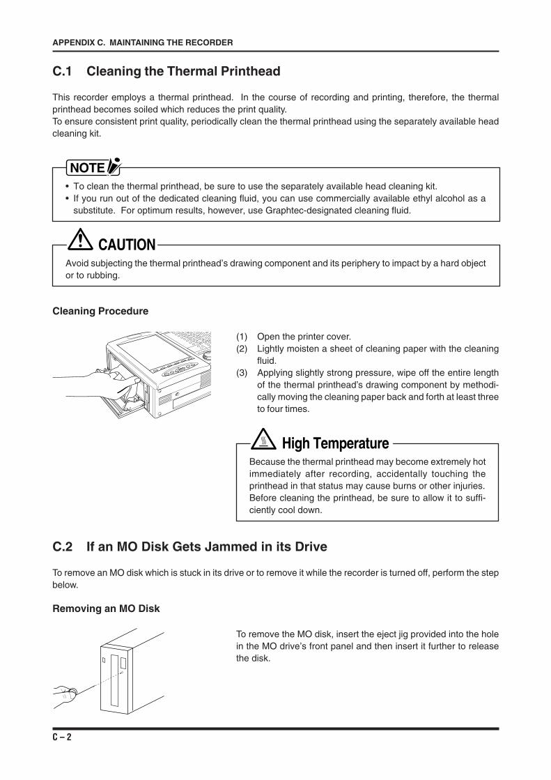
C – 2
APPENDIX C. MAINTAINING THE RECORDER
C.1 Cleaning the Thermal Printhead
This recorder employs a thermal printhead. In the course of recording and printing, therefore, the thermalprinthead becomes soiled which reduces the print quality.To ensure consistent print quality, periodically clean the thermal printhead using the separately available headcleaning kit.
NOTE• To clean the thermal printhead, be sure to use the separately available head cleaning kit.• If you run out of the dedicated cleaning fluid, you can use commercially available ethyl alcohol as a
substitute. For optimum results, however, use Graphtec-designated cleaning fluid.
CAUTIONAvoid subjecting the thermal printhead’s drawing component and its periphery to impact by a hard objector to rubbing.
Cleaning Procedure
(1) Open the printer cover.(2) Lightly moisten a sheet of cleaning paper with the cleaning
fluid.(3) Applying slightly strong pressure, wipe off the entire length
of the thermal printhead’s drawing component by methodi-cally moving the cleaning paper back and forth at least threeto four times.
High TemperatureBecause the thermal printhead may become extremely hotimmediately after recording, accidentally touching theprinthead in that status may cause burns or other injuries.Before cleaning the printhead, be sure to allow it to suffi-ciently cool down.
C.2 If an MO Disk Gets Jammed in its Drive
To remove an MO disk which is stuck in its drive or to remove it while the recorder is turned off, perform the stepbelow.
Removing an MO Disk
To remove the MO disk, insert the eject jig provided into the holein the MO drive’s front panel and then insert it further to releasethe disk.
D – 1
APPENDIX D. BEFORE REQUESTING SERVICE
APPENDIX DAPPENDIX DBEFORE REQUESTING SERVICE
This chapter describes the check procedures that shouldbe performed before requesting service.
D.1 BEFORE REQUESTING SERVICE
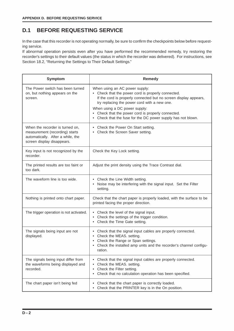
D – 2
APPENDIX D. BEFORE REQUESTING SERVICE
D.1 BEFORE REQUESTING SERVICE
In the case that this recorder is not operating normally, be sure to confirm the checkpoints below before request-ing service.If abnormal operation persists even after you have performed the recommended remedy, try restoring therecorder’s settings to their default values (the status in which the recorder was delivered). For instructions, seeSection 18.2, “Returning the Settings to Their Default Settings.”
Symptom
The Power switch has been turnedon, but nothing appears on thescreen.
When the recorder is turned on,measurement (recording) startsautomatically. After a while, thescreen display disappears.
Key input is not recognized by therecorder.
The printed results are too faint ortoo dark.
The waveform line is too wide.
Nothing is printed onto chart paper.
The trigger operation is not activated.
The signals being input are notdisplayed.
The signals being input differ fromthe waveforms being displayed andrecorded.
The chart paper isn’t being fed
Remedy
When using an AC power supply:• Check that the power cord is properly connected.
If the cord is properly connected but no screen display appears,try replacing the power cord with a new one.
When using a DC power supply:• Check that the power cord is properly connected.• Check that the fuse for the DC power supply has not blown.
• Check the Power On Start setting.• Check the Screen Saver setting.
Check the Key Lock setting.
Adjust the print density using the Trace Contrast dial.
• Check the Line Width setting.• Noise may be interfering with the signal input. Set the Filter
setting.
Check that the chart paper is properly loaded, with the surface to beprinted facing the proper direction.
• Check the level of the signal input.• Check the settings of the trigger condition.• Check the Time Gate setting.
• Check that the signal input cables are properly connected.• Check the MEAS. setting.• Check the Range or Span settings.• Check the installed amp units and the recorder’s channel configu-
ration.
• Check that the signal input cables are properly connected.• Check the MEAS. setting.• Check the Filter setting.• Check that no calculation operation has been specified.
• Check that the chart paper is correctly loaded.• Check that the PRINTER key is in the On position.
E – 1
APPENDIX E. EXTERNAL DIMENSIONS
APPENDIX EAPPENDIX EEXTERNAL DIMENSIONS
E.1 External Dimensions of the Standard Model(16 Channels)
E.2 External Dimensions of the Standard Model withWriting Table Attached (16 Channels)
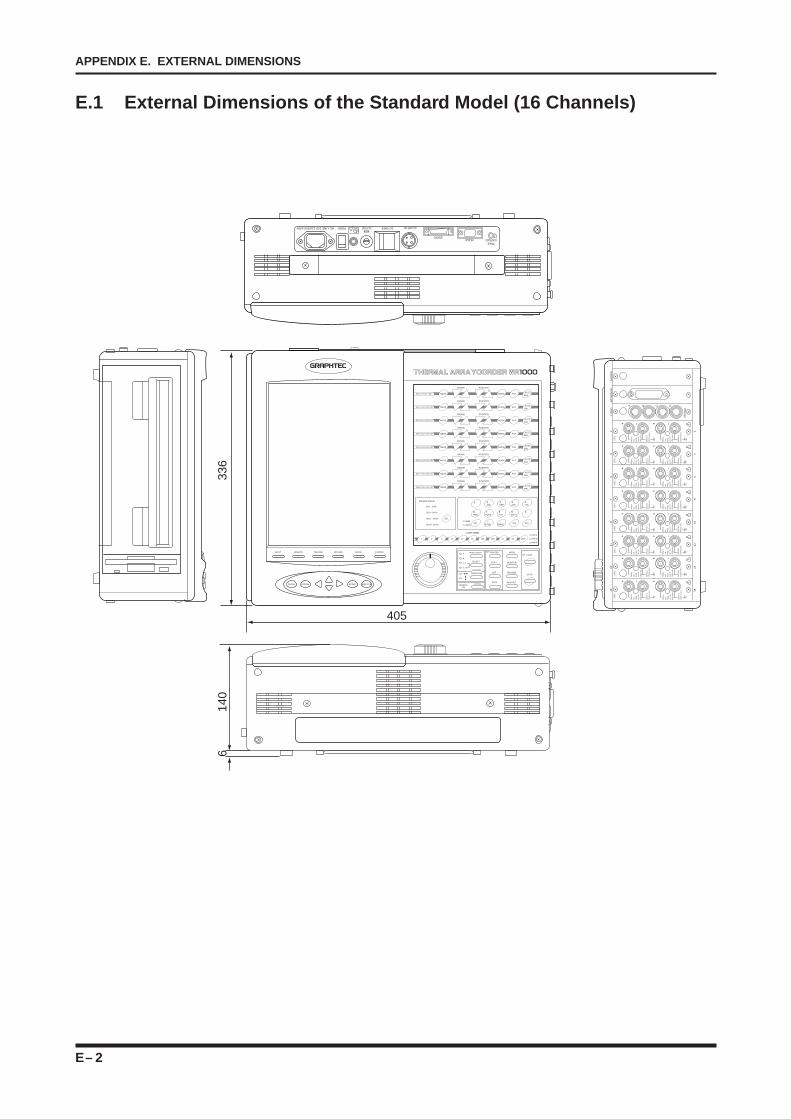
E – 2
APPENDIX E. EXTERNAL DIMENSIONS
AC-LINE 100-120/200-240V POWER DC-FUSE DC-POWER DC-LINE 12V
REMOTERS-232C
TRACECONTRAST
!
INPUT MEMORY TRIGGER RECORD JUDGE SYSTEM
CLOSE CANCEL ENTER EXECUTE
CH 1 / 9 / 17 / 25 MEAS. VERNI. FILT. AUTO
BAL.
POSITIONRANGE
CH 2 / 10 / 18 / 26 MEAS. VERNI. FILT. AUTO
BAL.
POSITIONRANGE
CH 3 / 11 / 19 / 27 MEAS. VERNI. FILT. AUTO
BAL.
POSITIONRANGE
CH 4 / 12 / 20 / 28 MEAS. VERNI. FILT. AUTO
BAL.
POSITIONRANGE
CH 5 / 13 / 21 / 29 MEAS. VERNI. FILT. AUTO
BAL.
POSITIONRANGE
CH 6 / 14 / 22 / 30 MEAS. VERNI. FILT. AUTO
BAL.
POSITIONRANGE
CH 7 / 15 / 23 / 31 MEAS. VERNI. FILT. AUTO
BAL.
POSITIONRANGE
CH 8 / 16 / 24 / 32 MEAS. VERNI. FILT. AUTO
BAL.
POSITIONRANGE
1 2 5 10 20 50 100 200 V1 V2 UNIT
1 2ABC
3DEF
4GHI
5JHL
6MNO
7PQRS
8TUV
9WXYZ
0
SEL.±
SYMB..
SPACEINS DEL.
NUM
ALPHA
mm/ s
mm/ m
mm/ h
CHART SPEED
PREAMP GROUP
CH 1 - CH 8
CH 9 - CH 16
CH 17 - CH 24
CH 24 - CH 32
SEL.
CAT
2
500V
p-p
max
.Ra
nge
up to
2V
30Vp
-p m
ax.
250V
Crm
s(7
10Vp
-p m
ax.)
500V
p-p
max
.Ra
nge
up to
2V
30Vp
-p m
ax.
250V
Crm
s(7
10Vp
-p m
ax.)
CAT
2
500V
p-p
max
.Ra
nge
up to
2V
30Vp
-p m
ax.
250V
Crm
s(7
10Vp
-p m
ax.)
CAT
2
500V
p-p
max
.Ra
nge
up to
2V
30Vp
-p m
ax.
250V
Crm
s(7
10Vp
-p m
ax.)
CAT
2
500V
p-p
max
.Ra
nge
up to
2V
30Vp
-p m
ax.
250V
Crm
s(7
10Vp
-p m
ax.)
CAT
2
500V
p-p
max
.Ra
nge
up to
2V
30Vp
-p m
ax.
250V
Crm
s(7
10Vp
-p m
ax.)
CAT
2
500V
p-p
max
.Ra
nge
up to
2V
30Vp
-p m
ax.
250V
Crm
s(7
10Vp
-p m
ax.)
CAT
2
500V
p-p
max
.Ra
nge
up to
2V
30Vp
-p m
ax.
250V
Crm
s(7
10Vp
-p m
ax.)
CAT
2
+ – + – !!+ – + –
!+ – + –
!+ – + –
!+ – + –
!+ – + –
!+ – + –
!+ – + –
500V
p-p
max
.Ra
nge
up to
2V
30Vp
-p m
ax.
250V
Crm
s(7
10Vp
-p m
ax.)
500V
p-p
max
.Ra
nge
up to
2V
30Vp
-p m
ax.
250V
Crm
s(7
10Vp
-p m
ax.)
500V
p-p
max
.Ra
nge
up to
2V
30Vp
-p m
ax.
250V
Crm
s(7
10Vp
-p m
ax.)
500V
p-p
max
.Ra
nge
up to
2V
30Vp
-p m
ax.
250V
Crm
s(7
10Vp
-p m
ax.)
500V
p-p
max
.Ra
nge
up to
2V
30Vp
-p m
ax.
250V
Crm
s(7
10Vp
-p m
ax.)
500V
p-p
max
.Ra
nge
up to
2V
30Vp
-p m
ax.
250V
Crm
s(7
10Vp
-p m
ax.)
500V
p-p
max
.Ra
nge
up to
2V
30Vp
-p m
ax.
250V
Crm
s(7
10Vp
-p m
ax.)
500V
p-p
max
.Ra
nge
up to
2V
30Vp
-p m
ax.
250V
Crm
s(7
10Vp
-p m
ax.)
25V
max
.A B C D
1513
119
75
31 2
46
810
1214
16
LOG
ICG
P-I
B/S
CS
IS
OU
ND
336
140
6
405
MODE / EVENT
SELECT
A
B
A, B
A & B
PRINTER
COPY
LIST
FEED
MODE
MONITOR
TRIGGER
MEM.OUT
START
STOP
LOCALREMOTE
CURSOR
DIRECTION
E.1 External Dimensions of the Standard Model (16 Channels)
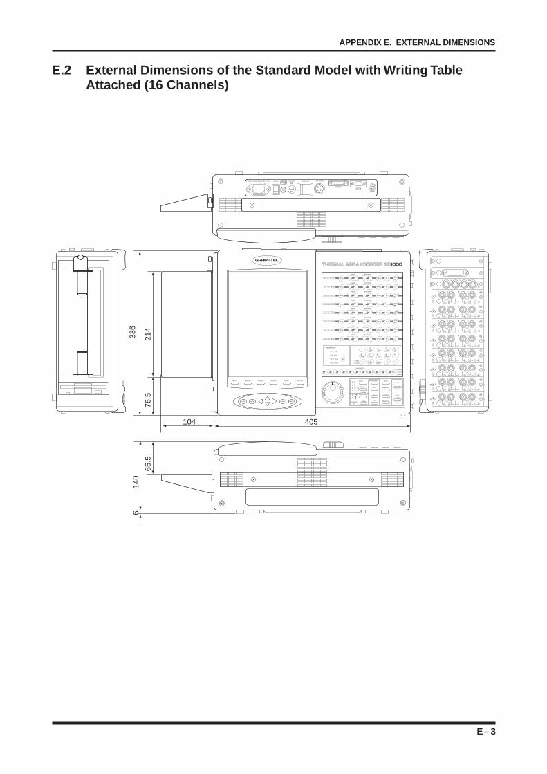
E – 3
APPENDIX E. EXTERNAL DIMENSIONS
AC-LINE 100-120/200-240V POWER DC-FUSE DC-POWER DC-LINE 12V
REMOTERS-232C
TRACECONTRAST
!
CAT
2
500V
p-p
max
.Ra
nge
up to
2V
30Vp
-p m
ax.
250V
Crm
s(7
10Vp
-p m
ax.)
500V
p-p
max
.Ra
nge
up to
2V
30Vp
-p m
ax.
250V
Crm
s(7
10Vp
-p m
ax.)
CAT
2
500V
p-p
max
.Ra
nge
up to
2V
30Vp
-p m
ax.
250V
Crm
s(7
10Vp
-p m
ax.)
CAT
2
500V
p-p
max
.Ra
nge
up to
2V
30Vp
-p m
ax.
250V
Crm
s(7
10Vp
-p m
ax.)
CAT
2
500V
p-p
max
.Ra
nge
up to
2V
30Vp
-p m
ax.
250V
Crm
s(7
10Vp
-p m
ax.)
CAT
2
500V
p-p
max
.Ra
nge
up to
2V
30Vp
-p m
ax.
250V
Crm
s(7
10Vp
-p m
ax.)
CAT
2
500V
p-p
max
.Ra
nge
up to
2V
30Vp
-p m
ax.
250V
Crm
s(7
10Vp
-p m
ax.)
CAT
2
500V
p-p
max
.Ra
nge
up to
2V
30Vp
-p m
ax.
250V
Crm
s(7
10Vp
-p m
ax.)
CAT
2
500V
p-p
max
.Ra
nge
up to
2V
30Vp
-p m
ax.
250V
Crm
s(7
10Vp
-p m
ax.)
500V
p-p
max
.Ra
nge
up to
2V
30Vp
-p m
ax.
250V
Crm
s(7
10Vp
-p m
ax.)
500V
p-p
max
.Ra
nge
up to
2V
30Vp
-p m
ax.
250V
Crm
s(7
10Vp
-p m
ax.)
500V
p-p
max
.Ra
nge
up to
2V
30Vp
-p m
ax.
250V
Crm
s(7
10Vp
-p m
ax.)
500V
p-p
max
.Ra
nge
up to
2V
30Vp
-p m
ax.
250V
Crm
s(7
10Vp
-p m
ax.)
500V
p-p
max
.Ra
nge
up to
2V
30Vp
-p m
ax.
250V
Crm
s(7
10Vp
-p m
ax.)
500V
p-p
max
.Ra
nge
up to
2V
30Vp
-p m
ax.
250V
Crm
s(7
10Vp
-p m
ax.)
500V
p-p
max
.Ra
nge
up to
2V
30Vp
-p m
ax.
250V
Crm
s(7
10Vp
-p m
ax.)
25V
max
.A B C D
1513
119
75
31 2
46
810
1214
16
LOG
ICG
P-I
B/S
CS
IS
OU
ND
140
6
65.5
INPUT MEMORY TRIGGER RECORD JUDGE SYSTEM
CLOSE CANCEL ENTER EXECUTE
CH 1 / 9 / 17 / 25 MEAS. VERNI. FILT. AUTO
BAL.
POSITIONRANGE
CH 2 / 10 / 18 / 26 MEAS. VERNI. FILT. AUTO
BAL.
POSITIONRANGE
CH 3 / 11 / 19 / 27 MEAS. VERNI. FILT. AUTO
BAL.
POSITIONRANGE
CH 4 / 12 / 20 / 28 MEAS. VERNI. FILT. AUTO
BAL.
POSITIONRANGE
CH 5 / 13 / 21 / 29 MEAS. VERNI. FILT. AUTO
BAL.
POSITIONRANGE
CH 6 / 14 / 22 / 30 MEAS. VERNI. FILT. AUTO
BAL.
POSITIONRANGE
CH 7 / 15 / 23 / 31 MEAS. VERNI. FILT. AUTO
BAL.
POSITIONRANGE
CH 8 / 16 / 24 / 32 MEAS. VERNI. FILT. AUTO
BAL.
POSITIONRANGE
1 2 5 10 20 50 100 200 V1 V2 UNIT
NUM
ALPHA
mm/ s
mm/ m
mm/ h
CHART SPEED
PREAMP GROUP
CH 1 - CH 8
CH 9 - CH 16
CH 17 - CH 24
CH 24 - CH 32
SEL.
336
405104
76.5
214
MODENT
SELECT
A
B
A, B
A & B
PRINTER
COPY
LIST
FEED
MODE
MONITOR
TRIGGER
MEM.OUT
START
STOP
LOCALREMOTE
CURSOR
DIRECTION
1 2 ABC
3DEF
4 GHI
5JHL
6MNO
7PQRS
8TUV
9 WXYZ
0
SEL.±
SYMB..
SPACEINS DEL.
!+ – + –
!+ – + –
!+ – + –
!+ – + –
!+ – + –
!+ – + –
!+ – + –
!+ – + –
E.2 External Dimensions of the Standard Model with Writing TableAttached (16 Channels)

E – 4
APPENDIX E. EXTERNAL DIMENSIONS