Embed Size (px)
Citation preview
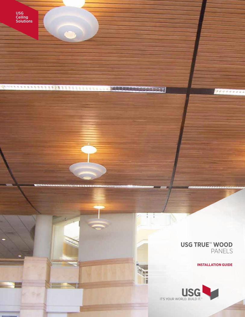
USG Ceiling Solutions
USG TRUE™ WOOD PANELS
INSTALLATION GUIDE
INSTALLATION GUIDE
1
USG TRUE™ WOOD PANELS
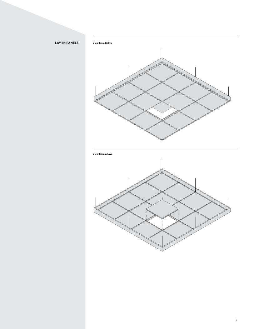
USG True™ Wood Lay-In panels work just like traditional acoustical panels. Available in many wood finishes and four perforation patterns.
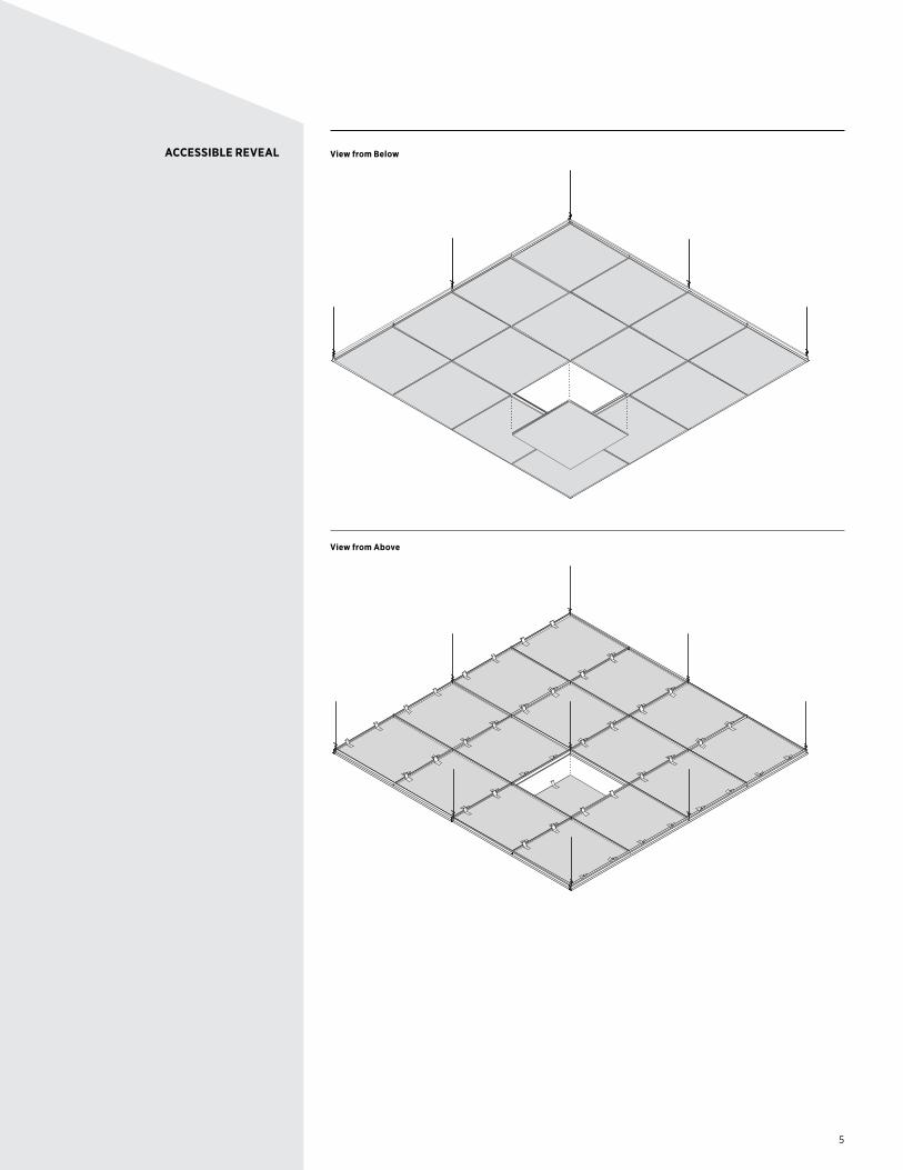
USG True™ Wood Accessible Reveal panels install on a traditional suspension system and provide a clean, uninterrupted wood ceiling with complete access to the plenum. Available in many wood finishes and four perforation patterns.
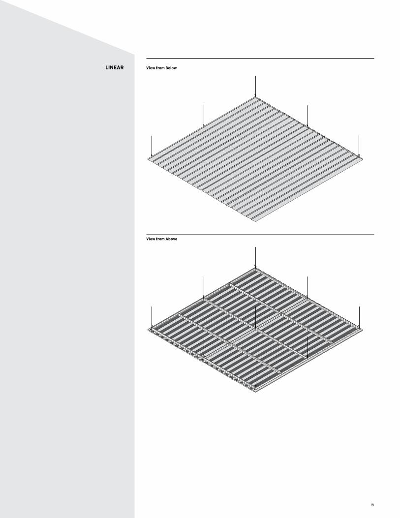
USG True™ Wood Linear panels are available in a variety of finishes and install directly to USG drywall grid system, making it great for large open spaces.
2 USG True™ Wood System Overview7 Lay-In Components9 Lay-In Applications12 Large Panel Installations13 Accessible Reveal Components16 Accessible Reveal Applications19 Linear Components21 Linear Applications
26 Perforations27 Finishes28 Application Guide Specifications
Technical Service800 USG.4YOU (874-4968)
Web Siteusg.com
CHOOSE YOUR SYSTEM
UNDERSTAND YOUR SYSTEM
SPECIFY YOUR SYSTEM
FOR MORE INFORMATION
2
SYSTEM OVERVIEW USG True™ Wood Lay-In panels work just like traditional acoustical panels. Available in many wood finishes and four perforation patterns.
USG True™ Wood Accessible Reveal panels install on a traditional suspension system and provide a clean, uninterrupted wood ceiling with complete access to the plenum. Available in many wood finishes and four perforation patterns.
USG True™ Wood Linear panels are available in a variety of finishes and install directly to USG drywall grid system, making it great for large open spaces.
USG True Wood Lay-In panels and Accessible Reveal panels come in 2' x 2' and 2' x 4' sizes as a standard.
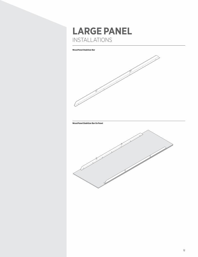
Plank size panels (2' x 6', 2' x 8', 20" x 60", 30" x 60") require the installation of wood panel stabilizer bars.
USG True Wood Linear panels come in nominal 4" x 96" and 6" x 96" plank sizes and install with a 3/4 inch gap. They can also be installed with no gap, edge to edge.
USG True Wood Lay-In is available for both 15/16" USG Donn® Brand DX®, 9/16" Centricee™ and 9/16" Fineline® suspension systems. All Lay-In tiles have a 5/16" Shadowline or Fineline edge standard. Panels may be field-cut at wall and columns but otherwise should be used in full modules.
USG True Wood Accessible Reveal tiles install on to 15/16" USG Donn Brand DX grid only, the reveal created by the abutting tiles leaves a 3/8" gap that conceals the suspension system. Accessible Reveal tile should be used in full modules, but provisions can be made to accommodate field-cut conditions.
USG True Wood Linear is fastened directly to drywall suspension system, and special considerations have to be taken for access and field-cut conditions.
Optional USG Compässo™ trim may be used with USG True Wood Lay-In and Accessible Reveal ceilings for a finished appearance at exposed edges. See brochure IC400 in the USG Specialty Ceilings Binder for more information.
USG True Wood perimeter trim can be used with all USG True Wood systems to ensure a panel species and perimeter trim wood species match.
Perforated Lay-In and Accessible Reveal panels with a Acoustibond™ sound backer achieve .60 NRC when installed in an enclosed plenum (18" depth min.). Available fiberglass backing provides even greater acoustical performance.
Installation shall be done only when the temperature and humidity closely approximate the interior conditions that will exist when the building is occupied. The heating and cooling systems shall be operating before, during and after installation, with the humidity of interior spaces maintained between 25% and 55%.
Building environmental conditions should be maintained in accordance with ASHRAE Standard 62.1, 2013.
It is important that plenums have proper ventilation, especially in high moisture areas. There shall be no excessive buildup of heat in the ceiling areas.
Prior to the start of installation, all exterior windows and doors are to be in place, glazed and weather-stripped. The roof is to be watertight, and all wet trades' work is to be completed and thoroughly dry.
Refer to CISCA Wood Ceilings Technical Guidelines for best practices on installing wood ceilings.Mechanical, electrical and other utility service installations above the ceiling plane shall have been completed. No materials should rest against, or wrap around, the ceiling suspension components or connecting hangers.
USG TRUE™ WOOD SYSTEMS
SIZES
SUSPENSION SYSTEM
PERIMETER DETAILS
ACOUSTICAL PERFORMANCE
PROJECT CONDITIONS
3
DELIVERY, STORAGE AND HANDLING
CUTTING PANELS
SCRATCH REPAIR
MATERIAL LIST
USG TRUE™ WOOD PRODUCTS ARE FSC CERTIFIED
USG True Wood shall be delivered to the project site in original, unopened packages. USG True Wood shall be stored flat and level in a fully enclosed space. The ceiling panels shall be stored off the floor. Care in handling must be exercised to avoid damage.
USG True Wood panels should be cut face up. Eye protection should be worn.
USG True Wood may be cut with a variety of tools including table saws, circular saws, jig saws and hole saws. Please follow the safety instructions issued by the power tool manufacturer.
A miter saw or table saw are the best choices for maintaining a clean, straight cut. For portable circular saws (Skilsaws®), use either 24 or 40 tooth carbide blades to cut USG True Wood.
For making holes for can lights, a hole saw is recommended. A jigsaw can also be used. Use fine tooth blades that are specified for cutting veneers.
A repair kit (foam brush and stain) is included with each USG True Wood order. This kit can be used after installation is complete and should be left with the building owner.
• #8 1/2" wood lath screws• 1-1/4" fine threaded drywall screws• Large spring clamps• Miter saw• Table saw or circular saw• Jig saw• Hole saw and drill• Nail set• Hole punch• 1-1/4" trim nails• MAC2 clips• Can of black spray paint
FSC stands for the Forest Stewardship Council. FSC certification is a voluntary, market-based tool for forest conservation. Consumer demand for FSC-certified products encourages more responsible forest management. FSC tracks products from forest to job site. Products that are responsibly harvested and/or from verified recycled sources are identified with the FSC logo.
4
LAY-IN PANELS View from Below
View from Above
5
ACCESSIBLE REVEAL View from Below
View from Above
6
LINEAR View from Below
View from Above
7
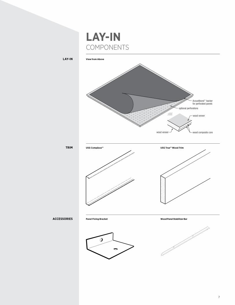
LAY-IN COMPONENTS
View from Above
Acoustibond™ backerfor perforated panels
optional perforations
wood composite core
wood veneer
wood veneer
USG Compässo™ USG True™ Wood Trim
Panel Fixing Bracket Wood Panel Stabilizer Bar
LAY-IN
TRIM
ACCESSORIES
8
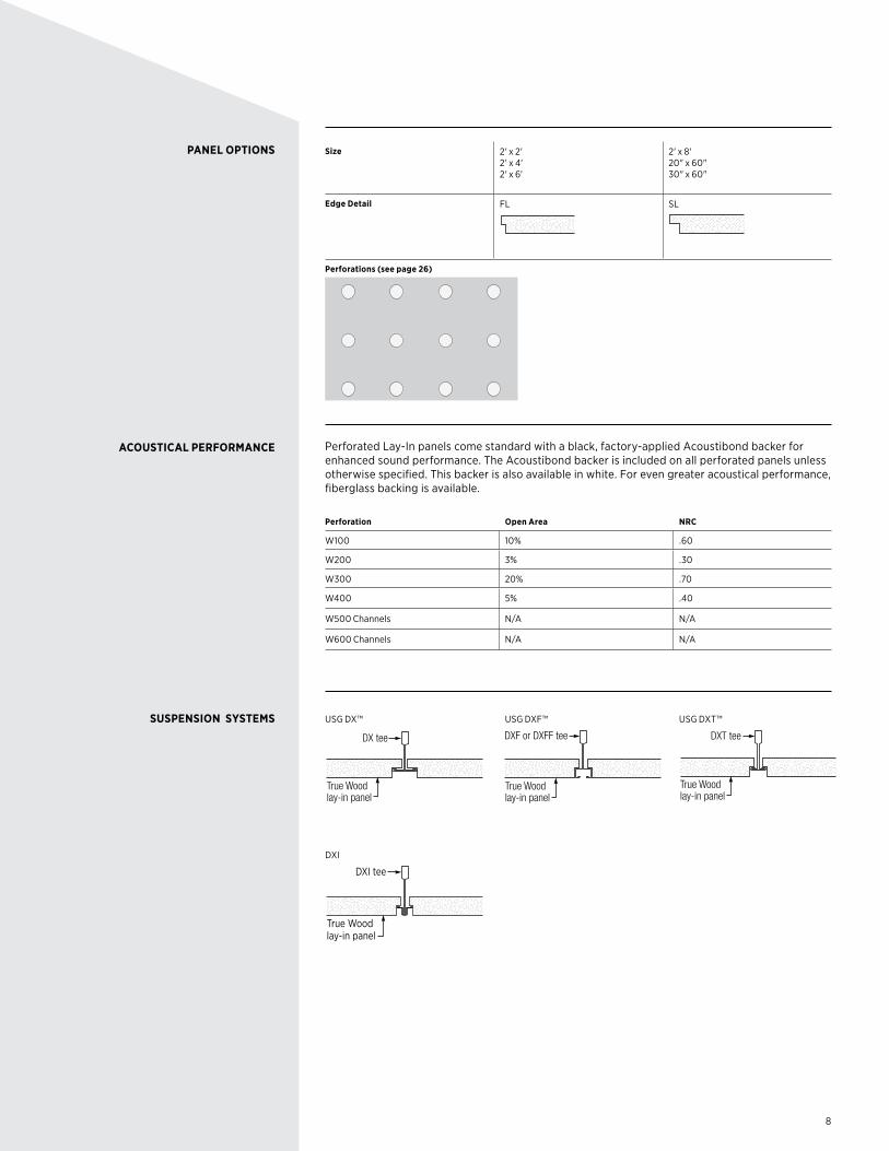
PANEL OPTIONS
ACOUSTICAL PERFORMANCE
SUSPENSION SYSTEMS
Size 2' x 2' 2' x 4' 2' x 6'
2' x 8' 20" x 60" 30" x 60"
Edge Detail FL SL
Perforations (see page 26)
W400
Perforated Lay-In panels come standard with a black, factory-applied Acoustibond backer for enhanced sound performance. The Acoustibond backer is included on all perforated panels unless otherwise specified. This backer is also available in white. For even greater acoustical performance, fiberglass backing is available.
Perforation Open Area NRC
W100 10% .60
W200 3% .30
W300 20% .70
W400 5% .40
W500 Channels N/A N/A
W600 Channels N/A N/A
USG DX™
True Wood lay-in panel
DX tee
USG DXF™
True Wood lay-in panel
DXF or DXFF tee
USG DXT™
True Wood lay-in panel
DXT tee
DXI
True Wood lay-in panel
DXI tee
9
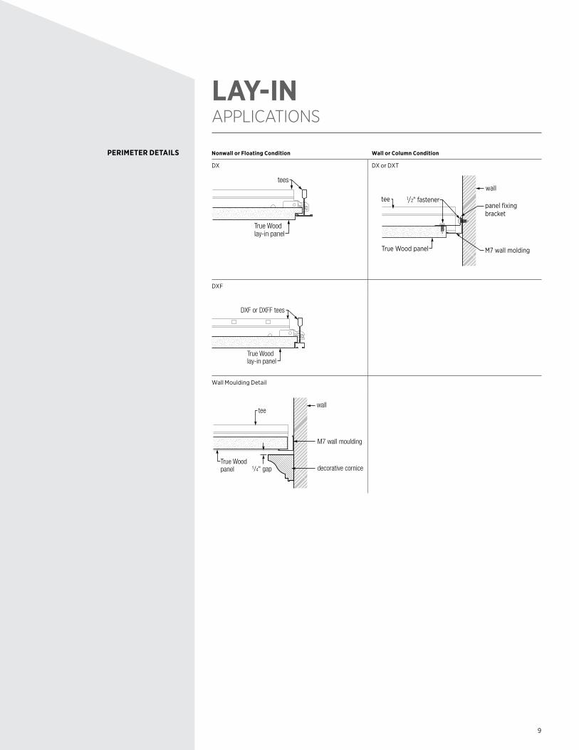
LAY-IN APPLICATIONS
Nonwall or Floating Condition Wall or Column Condition
DX DX or DXT
True Wood lay-in panel
tees
1/2" fastener
wall
tee
True Wood panel
panel fixing bracket
M7 wall molding
DXF
True Wood lay-in panel
DXF or DXFF tees
Wall Moulding Detail
M7 wall moulding
1/4" gap
wall
decorative cornice
tee
True Wood panel
PERIMETER DETAILS

10
Optional USG Compässo™ edge trim in 2-1/4", 4", 6", 8", 10" and 12" heights may be added for a finished appearance at exposed edges.
10"
9/16"
8"
9/16"
12"
9/16"
4"
9/16"
21/4"
9/16"6"
9/16"
Parallel (On Module)
DXF
4" Compasso trim
Compasso attachmentclip
True Wood lay-in panel
DXF or DXFF tees
DXF (Isometric)
DXF
True Wood lay-in panel
DXT tees
4" Compasso trim
Compasso attachmentclip
Perpendicular (Off Module)
DXF
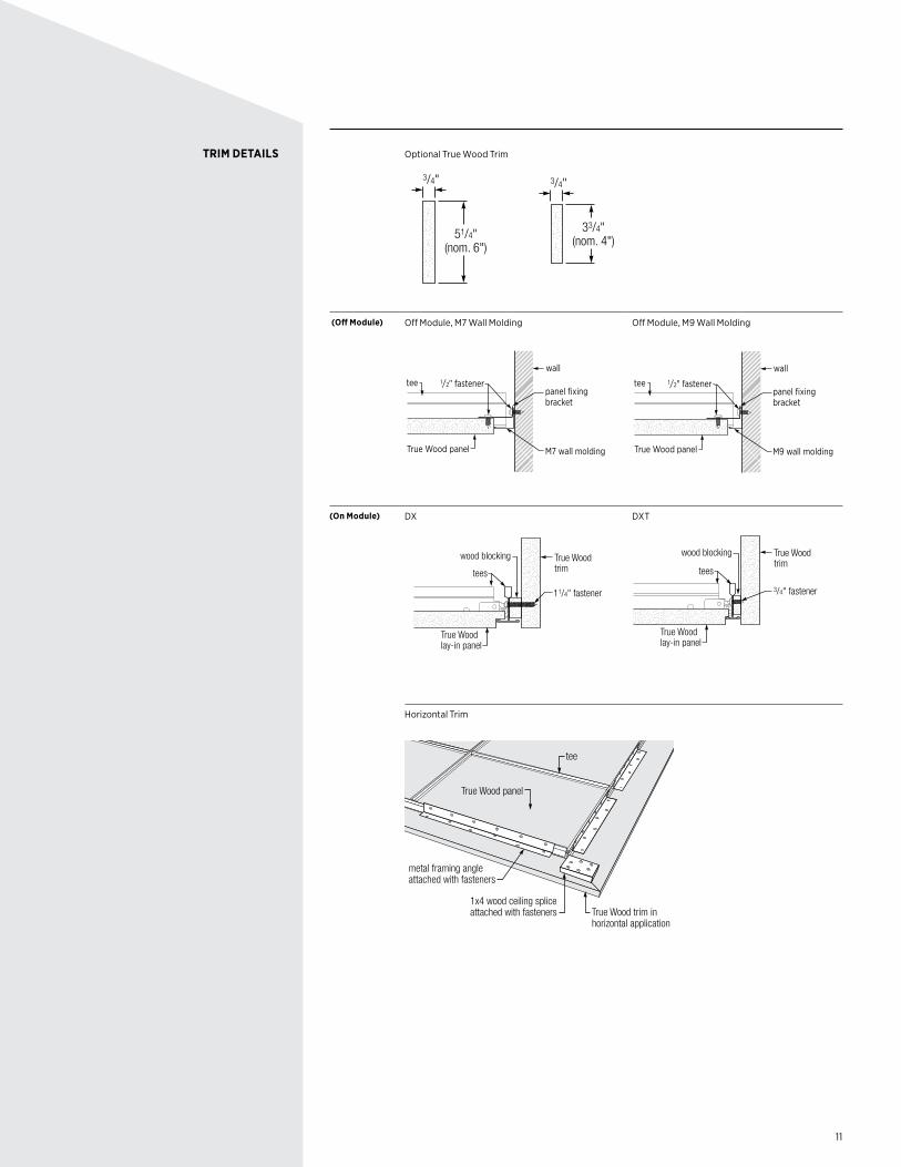
TRIM DETAILS
11
Optional True Wood Trim
51/4"(nom. 6")
3/4"
33/4"(nom. 4")
3/4"
(Off Module) Off Module, M7 Wall Molding
1/2" fastener
wall
tee
True Wood panel
panel fixing bracket
M7 wall molding
Off Module, M9 Wall Molding
1/2" fastener
wall
tee
True Wood panel
panel fixing bracket
M9 wall molding
(On Module) DX
True Wood trim
True Wood lay-in panel
wood blocking
tees
11/4" fastener
DXT
True Wood trim
True Wood lay-in panel
wood blocking
3/4" fastener
tees
Horizontal Trim
1x4 wood ceiling spliceattached with fasteners
metal framing angleattached with fasteners
tee
True Wood trim in horizontal application
True Wood panel
TRIM DETAILS
12
LARGE PANEL INSTALLATIONS
Wood Panel Stabilizer Bar
Wood Panel Stabilizer Bar On Panel
13
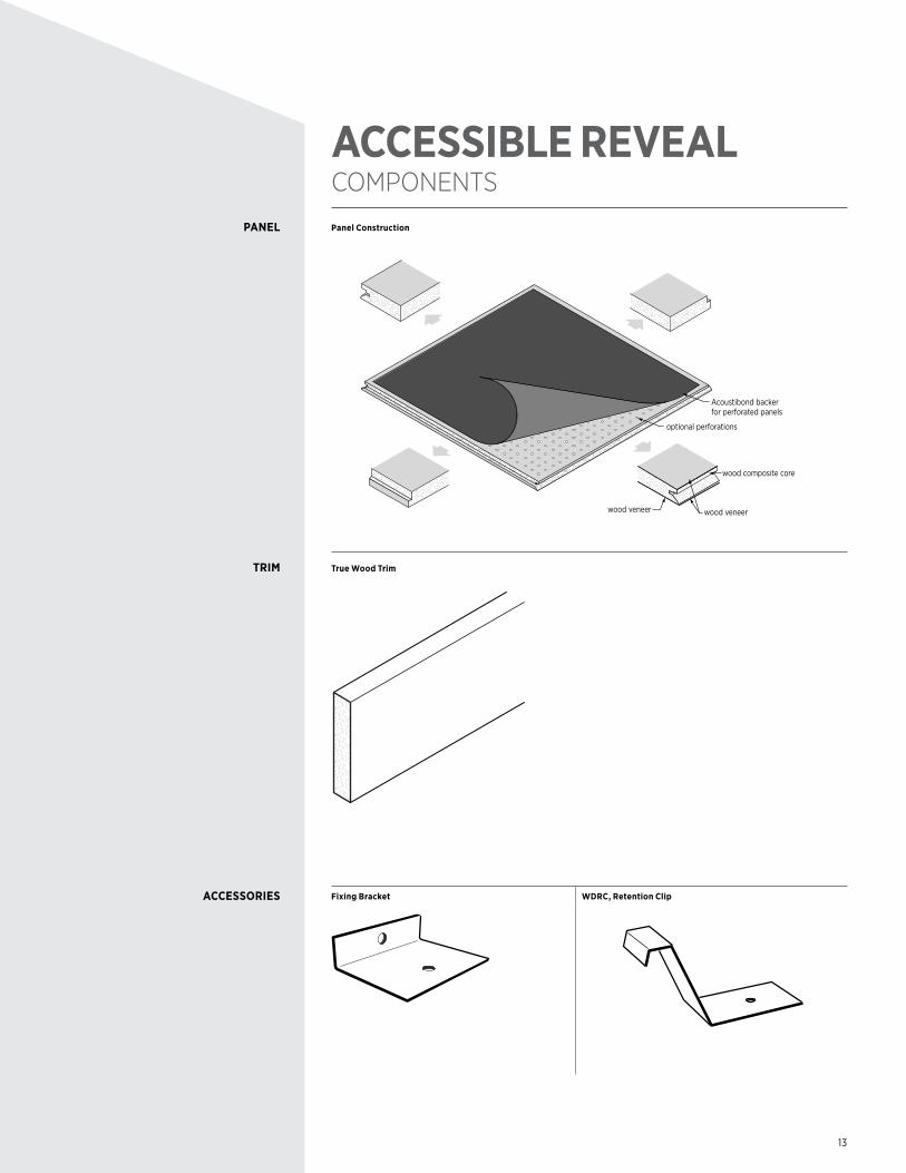
ACCESSIBLE REVEAL COMPONENTS
Panel Construction
optional perforations
wood composite core
wood veneer
Acoustibond backerfor perforated panels
wood veneer
True Wood Trim
Fixing Bracket WDRC, Retention Clip
PANEL
TRIM
ACCESSORIES
14
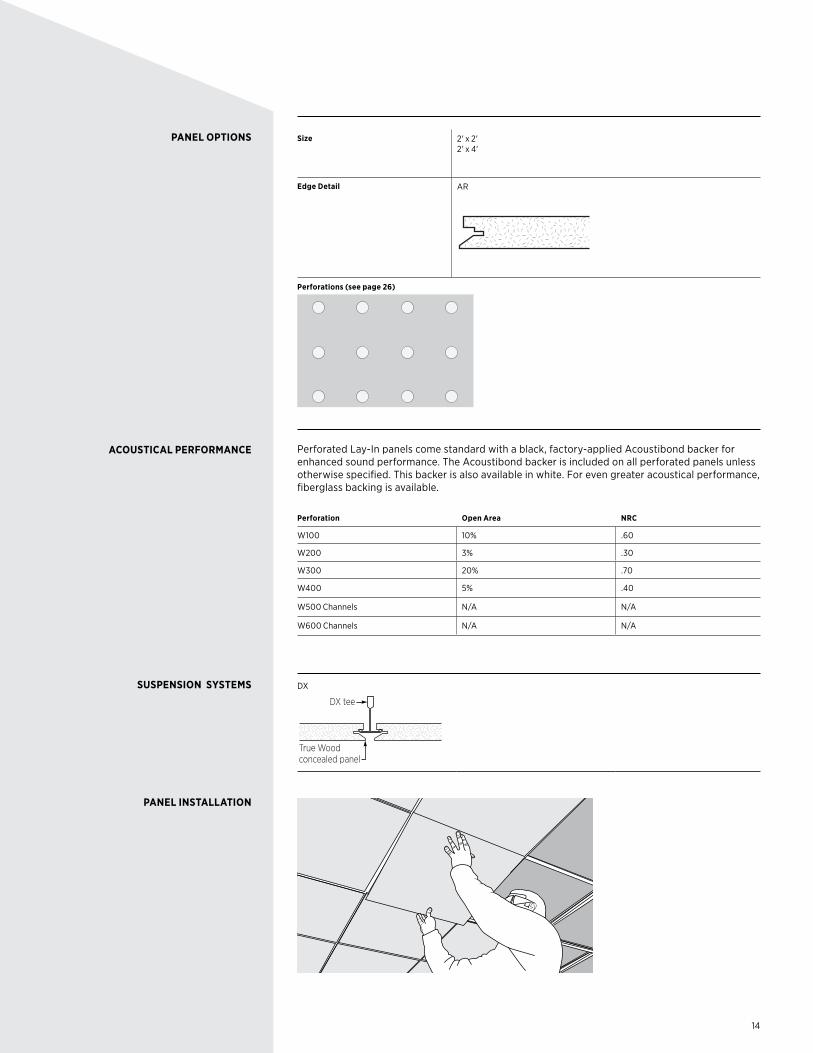
PANEL OPTIONS
ACOUSTICAL PERFORMANCE
SUSPENSION SYSTEMS
PANEL INSTALLATION
Size 2' x 2' 2' x 4'
Edge Detail AR
Perforations (see page 26)
W400
Perforated Lay-In panels come standard with a black, factory-applied Acoustibond backer for enhanced sound performance. The Acoustibond backer is included on all perforated panels unless otherwise specified. This backer is also available in white. For even greater acoustical performance, fiberglass backing is available.
Perforation Open Area NRC
W100 10% .60
W200 3% .30
W300 20% .70
W400 5% .40
W500 Channels N/A N/A
W600 Channels N/A N/A
DX
DX tee
True Wood concealed panel
15
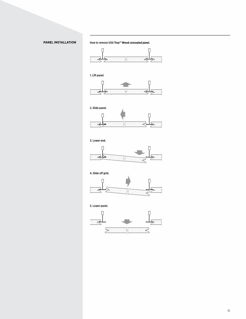
How to remove USG True™ Wood concealed panel.
1. Lift panel.
2. Slide panel.
3. Lower end.
4. Slide o� grid.
5. Lower panel.
PANEL INSTALLATION
16
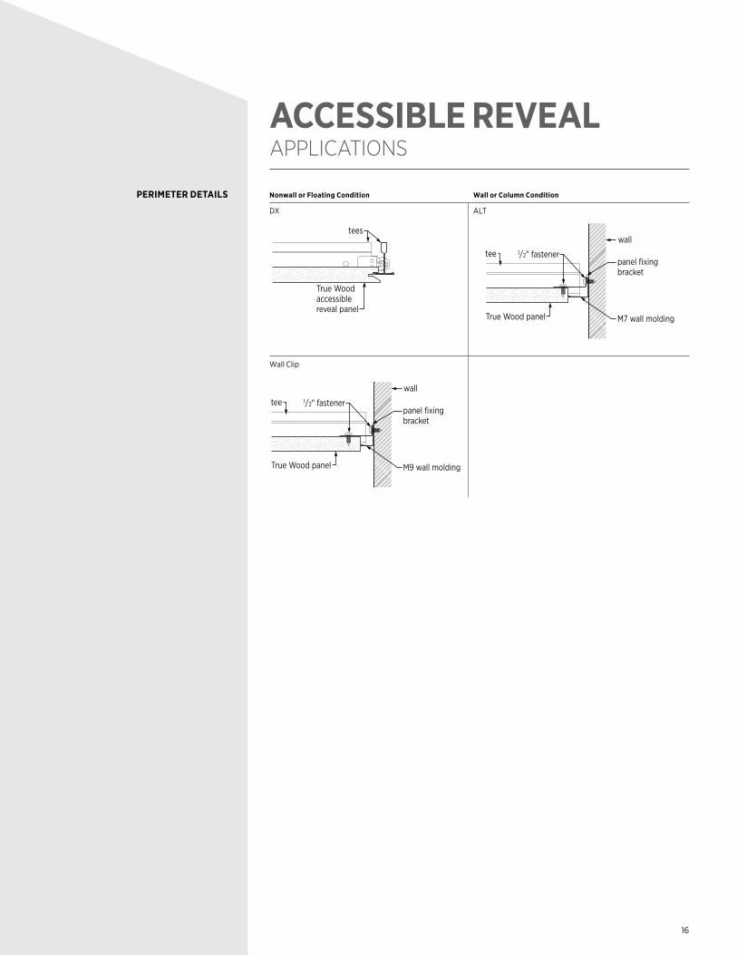
ACCESSIBLE REVEAL APPLICATIONS
Nonwall or Floating Condition Wall or Column Condition
DX ALT
True Wood accessible reveal panel
tees
1/2" fastener
wall
tee
True Wood panel
panel fixing bracket
M7 wall molding
Wall Clip
1/2" fastener
wall
tee
True Wood panel
panel fixing bracket
M9 wall molding
PERIMETER DETAILS
17
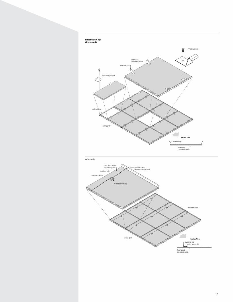
Retention Clips (Required)
retention clip
retention clip
wall molding
ceiling grid
Section View
True Wood concealed panel
1/4"-20 supplied
True Wood concealed panel
panel fixing bracket
Alternate
retention cable
attachment clipcarabiner clip
attachment clip
carabiner clip
retention cable threaded through grid
retention cable
ceiling gridSection View
USG True™ Wood concealed panel
True Wood concealed panel
18
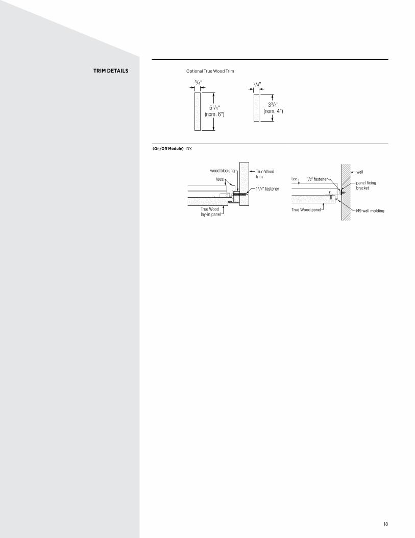
Optional True Wood Trim
51/4"(nom. 6")
3/4"
33/4"(nom. 4")
3/4"
(On/Off Module) DX
True Wood trim
True Wood lay-in panel
wood blocking
tees
11/4" fastener
1/2" fastener
wall
tee
True Wood panel
panel fixing bracket
M9 wall molding
TRIM DETAILS
19
LINEAR COMPONENTS
USG True Wood linear planks come finished on four sides with veneer and stain (if applicable). The two short ends or butt ends are not finished, and proper care must be taken to assure these ends are either hidden or treated in the field to match the exposed face.
USG True Wood linear plank system installs on USG Donn® Brand Drywall Suspension System, and the typical layout for this system is Main Tees (DGLW26) installed 4 feet on center hung every 4 feet along the main and cross tees installed every 4 feet between the mains. For USG True Wood linear system, the linear planks are screw attached to the cross tees and run parallel to the main tees.
USG True Wood linear planks are installed in a progressive fashion with the aesthetic felt toward the direction of the install. The spacing of the planks can be from zero to 7/8" of an inch. Great care should be taken to maintain the same spacing, and blocks or gauges should be used.Some portion of the grid may be exposed. These areas should be treated in the field with flat black paint that is suitable for galvanized material and the environment of the installation.
USG True Wood linear planks are screw attached with 1/2 wood lath screws from the back of the ceiling through the flange of the cross tee and into the plank. It is critical that the attachment of the planks be secure and that the fasteners are not "overdriven." In some cases it may be necessary to prepunch the grid flange to assure connection integrity.
Use spring clamps to position the plank in place and assure its spacing and alignment.
Splice Plates: Place butt joints over framing members. Otherwise, framing angle or wood can be used as a splice plate. Plan on using at least four 1/2" wood lath screws, two on each side of the splice. True Wood can be used with a biscuit joiner as well to join butt ends. Cutting butt ends at a 22-degree angle lessens the chance of seeing the exposed edge of the panel line.
Touch-up kits can be supplied by USG, but similar material can be obtained from a local retailer that carries wood finishing products. A sample should be tested for match and consistency.
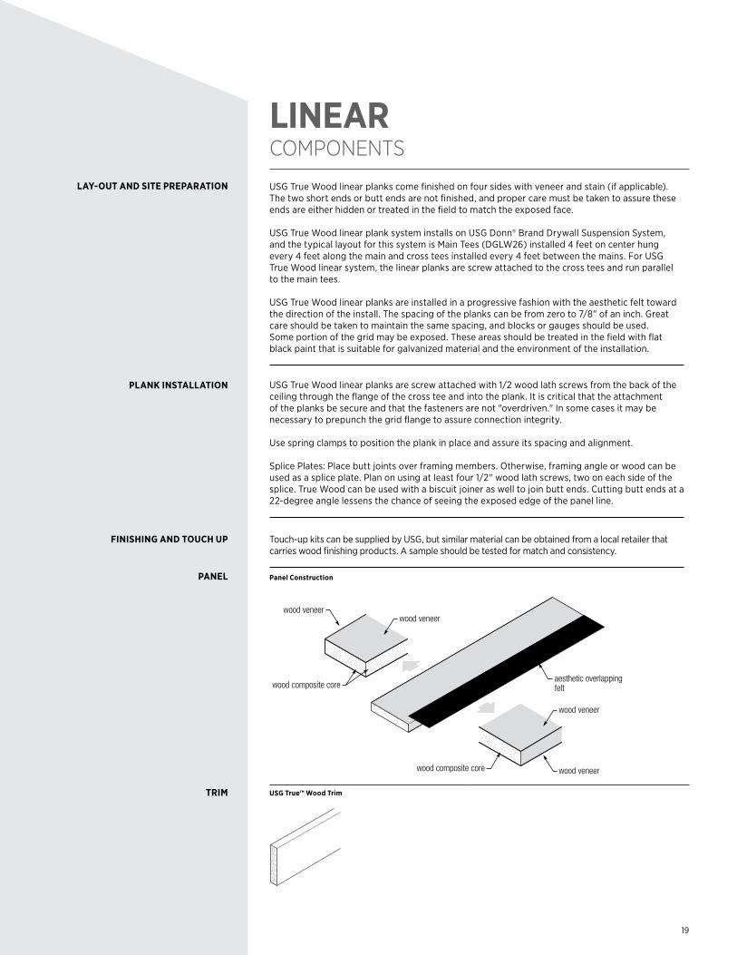
Panel Construction
wood composite core wood veneer
wood veneer
aesthetic overlapping felt
wood veneerwood veneer
wood composite core
USG True™ Wood Trim
LAY-OUT AND SITE PREPARATION
PLANK INSTALLATION
FINISHING AND TOUCH UP
PANEL
TRIM
20
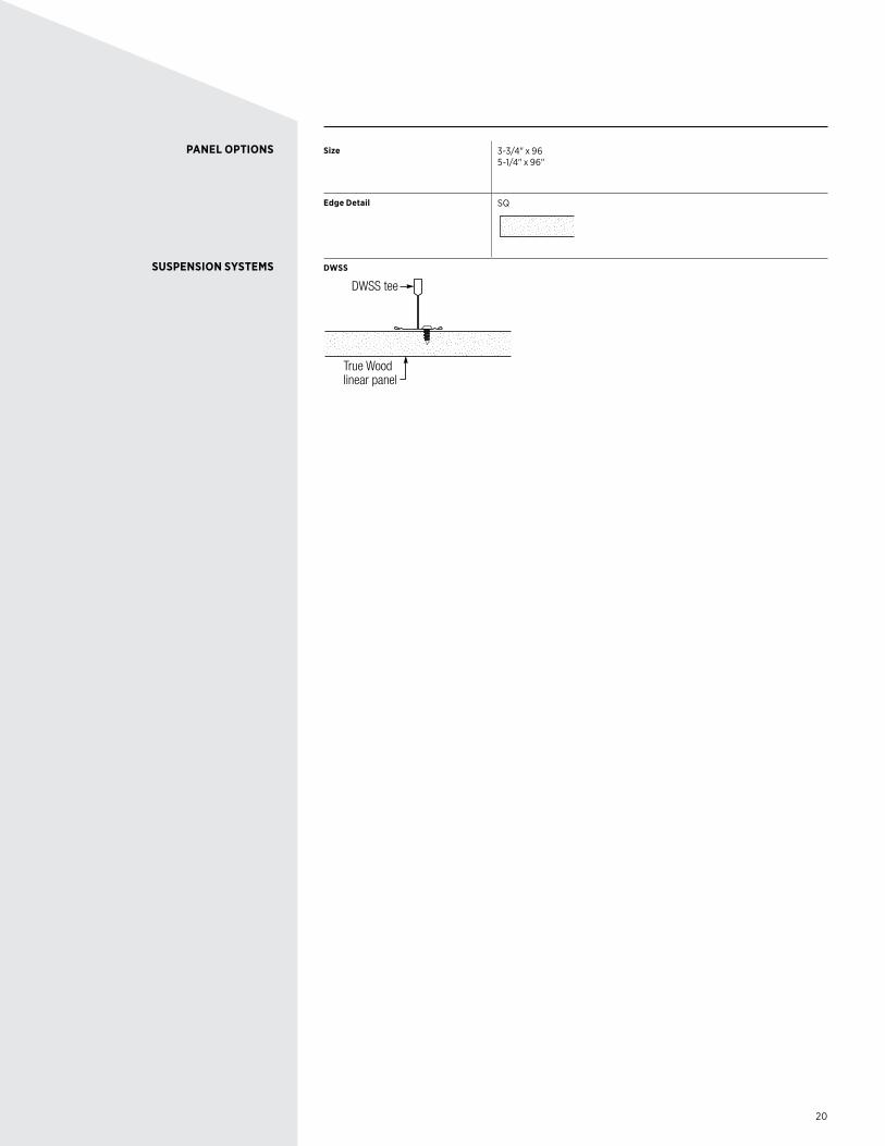
PANEL OPTIONS
SUSPENSION SYSTEMS
Size 3-3/4" x 96 5-1/4" x 96"
Edge Detail SQ
DWSS
DWSS tee
True Wood linear panel
21
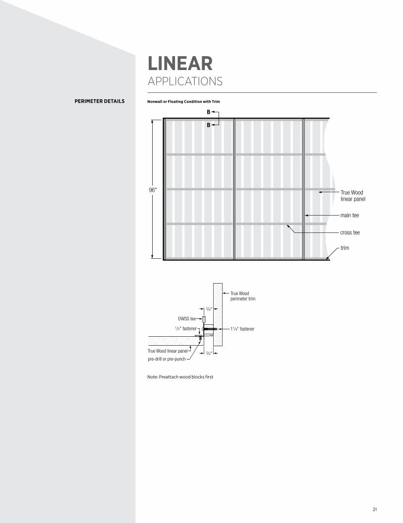
PERIMETER DETAILS
LINEAR APPLICATIONS
Nonwall or Floating Condition with Trim
96"
main tee
B
B
cross tee
True Wood linear panel
trim
3/4"
3/4"
pre-drill or pre-punch
True Wood perimeter trim
DWSS tee
True Wood linear panel
11/4" fastener1/2" fastener
Note: Preattach wood blocks first
22
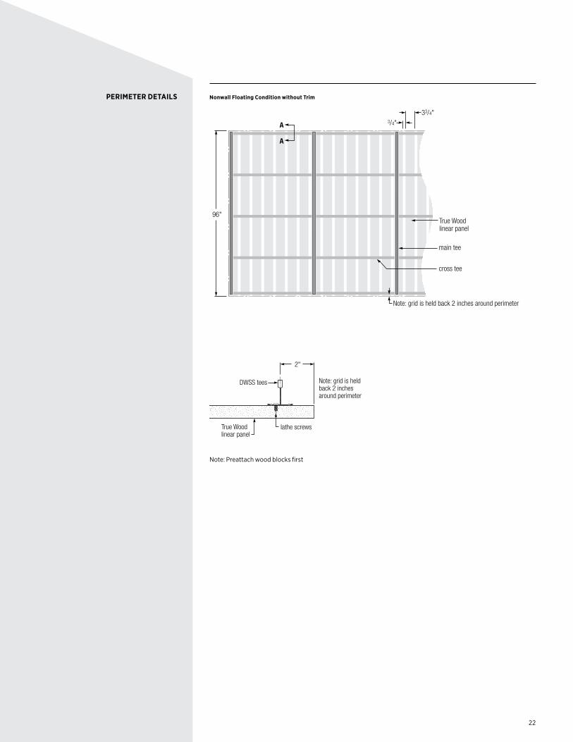
PERIMETER DETAILS Nonwall Floating Condition without Trim
96"
main tee
cross tee
A
A
True Wood linear panel
Note: grid is held back 2 inches around perimeter
3/4"
33/4"
2"
Note: grid is held back 2 inches around perimeter
lathe screwsTrue Wood linear panel
DWSS tees
Note: Preattach wood blocks first
23
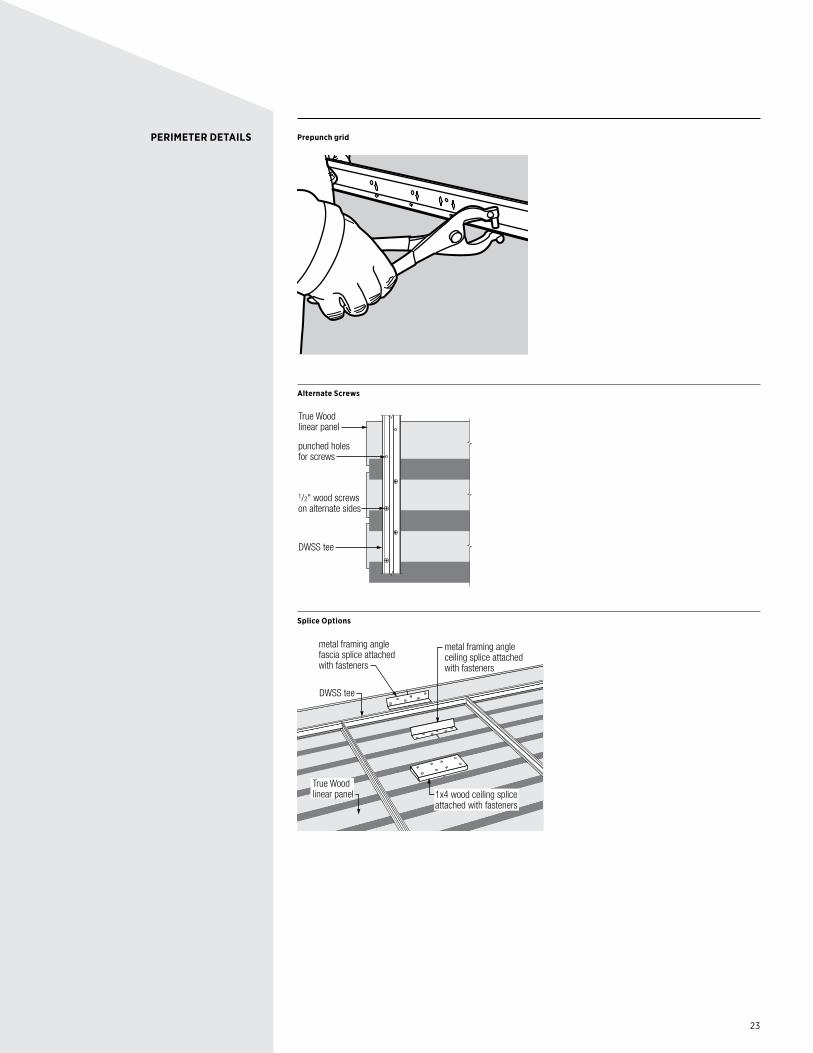
PERIMETER DETAILS Prepunch grid
Alternate Screws
1/2" wood screwson alternate sides
punched holesfor screws
True Wood linear panel
DWSS tee
Splice Options
1x4 wood ceiling spliceattached with fasteners
metal framing angle fascia splice attached with fasteners
metal framing angleceiling splice attached with fasteners
DWSS tee
True Wood linear panel
24
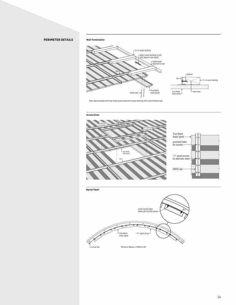
PERIMETER DETAILS Wall Termination
True Wood linear panelfinish nails
2 x 4 wood blocking
tee
attach wood blocking to grid with fastener (see detail)
metal angleattached to wall
Note: Approximately last three linear panels attached to wood blocking with wood finishing nails
finish nails
2 x 4 wood blockingtee
fastener
True Wood linear panel
Access Door
1/2" wood screwson both sides
True Wood linear panel
access panelassembly
tee
tee
1/2" wood screwson alternate sides
punched holesfor screws
True Wood linear panel
DWSS tee
Barrel Vault
True Wood linear panel
1/2" wood screw
curved tee Minimum Radius in DWSS is 39"
screw toward edge where grid touches panel
25
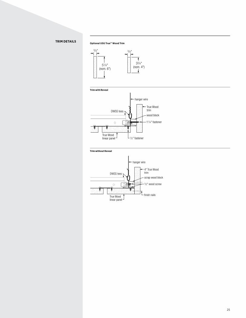
TRIM DETAILSOptional USG True™ Wood Trim
51/4"(nom. 6")
3/4"
33/4"(nom. 4")
3/4"
Trim with Reveal
True Wood trim
True Wood linear panel
wood block
1/2" fastener
DWSS tees
hanger wire
11/4" fastener
Trim without Reveal
4" True Wood trim
finish nailsTrue Wood linear panel
scrap wood block
1/2" wood screw
DWSS tees
hanger wire
26
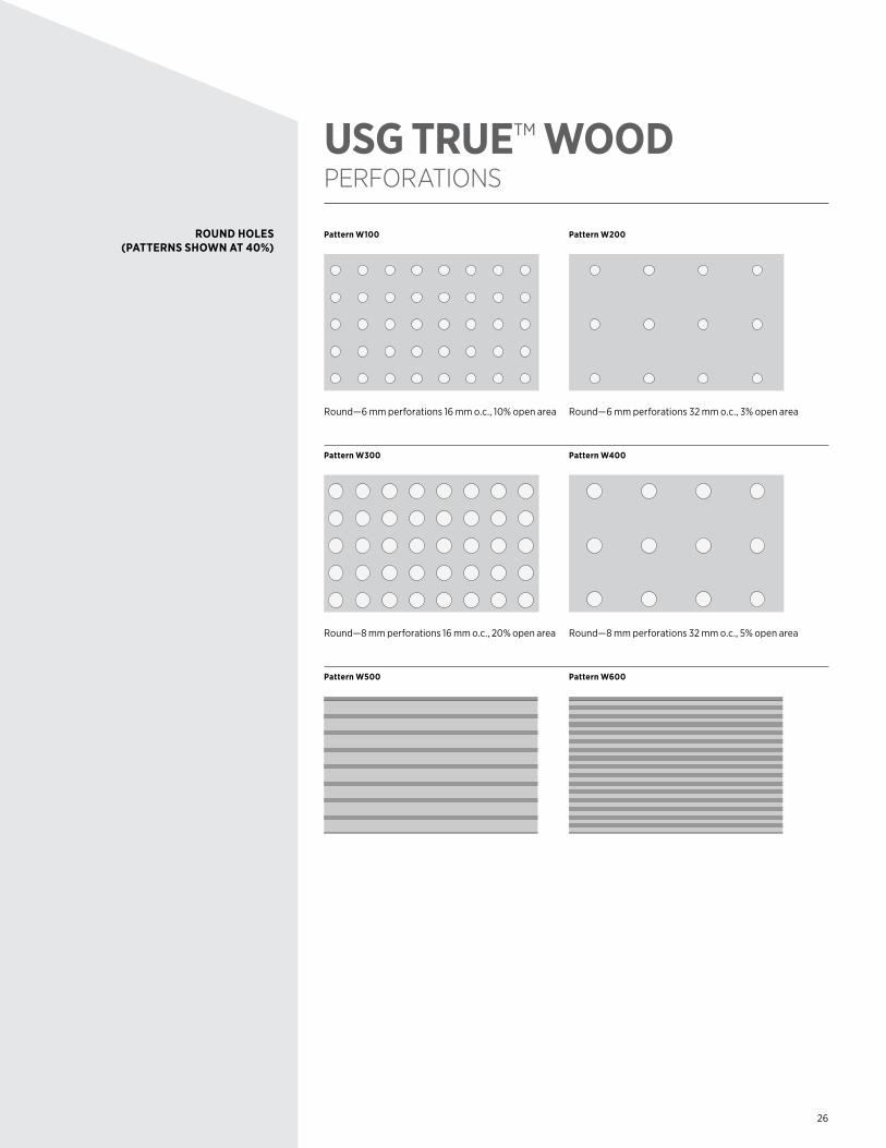
USG TRUETM WOOD PERFORATIONS
Pattern W100
W100
Round—6 mm perforations 16 mm o.c., 10% open area
Pattern W200
W200
Round—6 mm perforations 32 mm o.c., 3% open area
Pattern W300
W300
Round—8 mm perforations 16 mm o.c., 20% open area
Pattern W400
W400
Round—8 mm perforations 32 mm o.c., 5% open area
Pattern W500
W500
Pattern W600
W600
ROUND HOLES (PATTERNS SHOWN AT 40%)
27
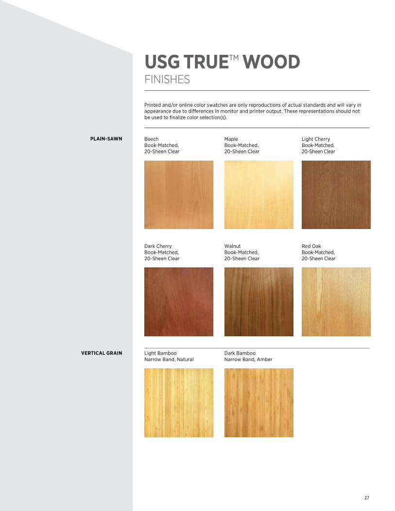
USG TRUETM WOOD FINISHES
Printed and/or online color swatches are only reproductions of actual standards and will vary in appearance due to differences in monitor and printer output. These representations should not be used to finalize color selection(s).
Beech Book-Matched, 20-Sheen Clear
Maple Book-Matched, 20-Sheen Clear
Light Cherry Book-Matched, 20-Sheen Clear
Dark CherryBook-Matched, 20-Sheen Clear
WalnutBook-Matched, 20-Sheen Clear
Red OakBook-Matched, 20-Sheen Clear
Light Bamboo Narrow Band, Natural
Dark Bamboo Narrow Band, Amber
PLAIN-SAWN
VERTICAL GRAIN

28
APPLICATION GUIDE SPECIFICATIONS
A. Drawings and general provisions of the Contract, including General and Supplementary Conditions and Division 1 Specification Sections, apply to this Section.
A. ASTM C635, Standard Specifications for Metal Suspension SystemsB. ASTM C636, Recommended Practice for Installation of Metal Suspension SystemC. ATSM E84, Standard Test Method for Surface Burning Characteristics of
Building MaterialsD. CISCA Ceiling Systems Installation HandbookE. CISCA Wood Ceilings Technical Guidelines
A. Section Includes: 1. Acoustical ceilings panels 2. Exposed grid suspension system 3. Wire hangers, fasteners, main runners, cross tees and wall angle moldingsB. Related Sections include the following: 1. Section 01 41 13 (01450) - Codes 2. Section 01 45 33 (01450) - Code-required Special Inspections and Procedures 3. Section 09 20 00 (09250) - Plaster and Gypsum Board 4. Division 23 (15) - HVAC 5. Division 26 (16) Sections - Electrical Work
A. Samples: Submit panel finish and suspension system main and cross tees for acceptance.
B. Shop drawings: 1. Reflected ceiling plans: Submit ceiling suspension system layout indicating dimensions,
lighting fixture locations and related mechanical components. 2. Assembly drawings: Indicate installation details, accessory attachments and installation of
related lighting fixtures and related mechanical system components. 3. Samples: Minimum 4 inch x 6 inch samples of specified acoustical panel; 8-inch-long
samples of exposed wall molding and suspension system, including main runner and 4 foot cross tees.
C. Manufacturer's data: 1. System details: Submit manufacturer's catalog cuts, literature or standard drawings
showing details of system with project conditions clearly identified and manufacturer's recommended installation instructions.
D. Maintenance materials: Provide _______ % of amount of main tees, cross tees and panels.
A. Delivery of materials: Deliver materials in original, unopened packages, clearly labeled with manufacturer's name, item description, specification number, type and class as applicable.
1.01 REFERENCES
1.02 SUMMARY
1.03 RELATED DOCUMENTS
1.04 SUBMITTALS
1.05 DELIVERY, STORAGE, AND HANDLING
29
1.05 DELIVERY, STORAGE AND HANDLING
CONT.
1.06 QUALITY ASSURANCE
1.07 PROJECT CONDITIONS
1.08 EXTRA MATERIALS
2.01 PRODUCTS AND MANUFACTURERS
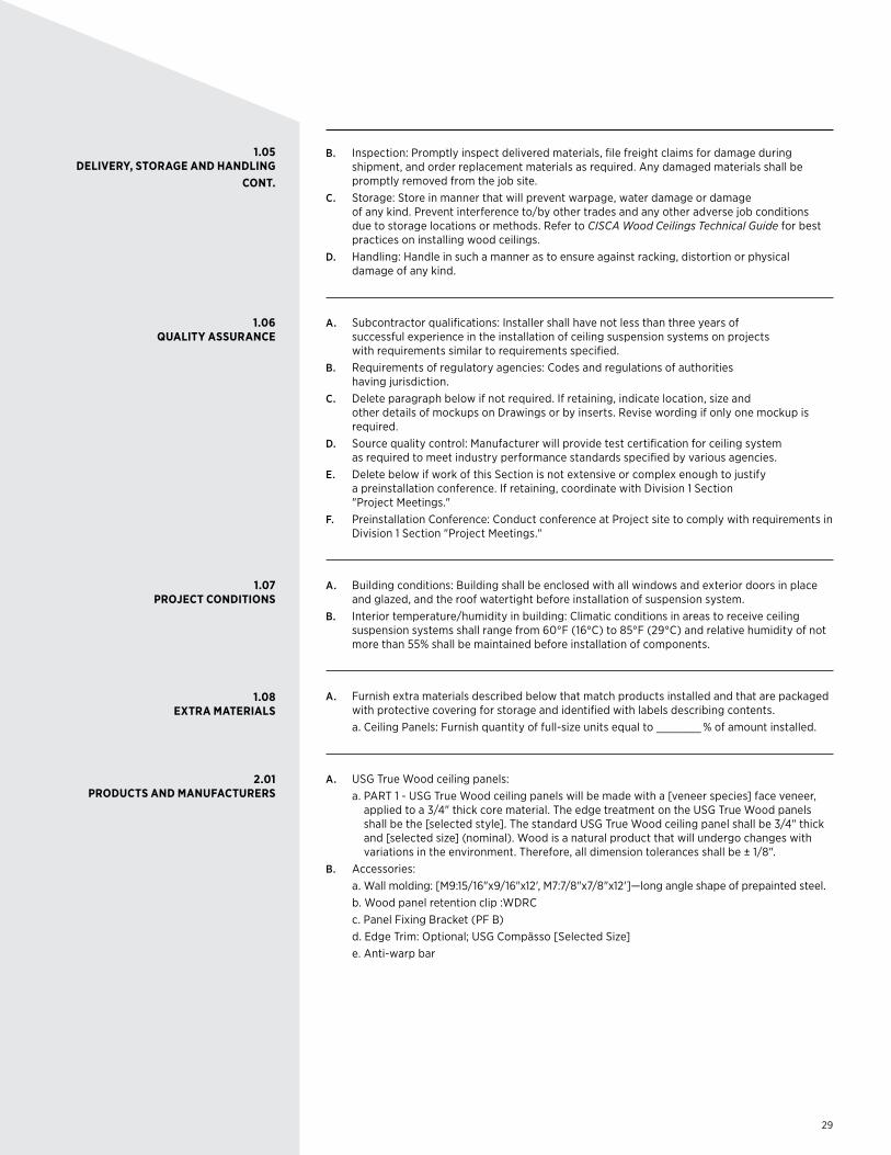
B. Inspection: Promptly inspect delivered materials, file freight claims for damage during shipment, and order replacement materials as required. Any damaged materials shall be promptly removed from the job site.
C. Storage: Store in manner that will prevent warpage, water damage or damage of any kind. Prevent interference to/by other trades and any other adverse job conditions due to storage locations or methods. Refer to CISCA Wood Ceilings Technical Guide for best practices on installing wood ceilings.
D. Handling: Handle in such a manner as to ensure against racking, distortion or physical damage of any kind.
A. Subcontractor qualifications: Installer shall have not less than three years of successful experience in the installation of ceiling suspension systems on projects with requirements similar to requirements specified.
B. Requirements of regulatory agencies: Codes and regulations of authorities having jurisdiction.
C. Delete paragraph below if not required. If retaining, indicate location, size and other details of mockups on Drawings or by inserts. Revise wording if only one mockup is required.
D. Source quality control: Manufacturer will provide test certification for ceiling system as required to meet industry performance standards specified by various agencies.
E. Delete below if work of this Section is not extensive or complex enough to justify a preinstallation conference. If retaining, coordinate with Division 1 Section "Project Meetings."
F. Preinstallation Conference: Conduct conference at Project site to comply with requirements in Division 1 Section "Project Meetings."
A. Building conditions: Building shall be enclosed with all windows and exterior doors in place and glazed, and the roof watertight before installation of suspension system.
B. Interior temperature/humidity in building: Climatic conditions in areas to receive ceiling suspension systems shall range from 60°F (16°C) to 85°F (29°C) and relative humidity of not more than 55% shall be maintained before installation of components.
A. Furnish extra materials described below that match products installed and that are packaged with protective covering for storage and identified with labels describing contents.
a. Ceiling Panels: Furnish quantity of full-size units equal to _______ % of amount installed.
A. USG True Wood ceiling panels: a. PART 1 - USG True Wood ceiling panels will be made with a [veneer species] face veneer,
applied to a 3/4" thick core material. The edge treatment on the USG True Wood panels shall be the [selected style]. The standard USG True Wood ceiling panel shall be 3/4" thick and [selected size] (nominal). Wood is a natural product that will undergo changes with variations in the environment. Therefore, all dimension tolerances shall be ± 1/8".
B. Accessories: a. Wall molding: [M9:15/16"x9/16"x12', M7:7/8"x7/8"x12']—long angle shape of prepainted steel. b. Wood panel retention clip :WDRC c. Panel Fixing Bracket (PF B) d. Edge Trim: Optional; USG Compässo [Selected Size] e. Anti-warp bar
30
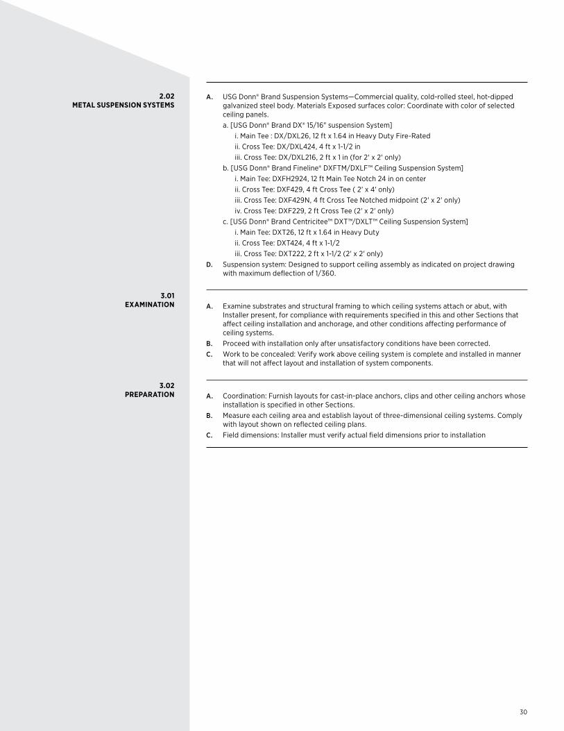
2.02 METAL SUSPENSION SYSTEMS
3.01 EXAMINATION
3.02 PREPARATION
A. USG Donn® Brand Suspension Systems—Commercial quality, cold-rolled steel, hot-dipped galvanized steel body. Materials Exposed surfaces color: Coordinate with color of selected ceiling panels.
a. [USG Donn® Brand DX® 15/16" suspension System] i. Main Tee : DX/DXL26, 12 ft x 1.64 in Heavy Duty Fire-Rated ii. Cross Tee: DX/DXL424, 4 ft x 1-1/2 in iii. Cross Tee: DX/DXL216, 2 ft x 1 in (for 2' x 2' only) b. [USG Donn® Brand Fineline® DXFTM/DXLF™ Ceiling Suspension System] i. Main Tee: DXFH2924, 12 ft Main Tee Notch 24 in on center ii. Cross Tee: DXF429, 4 ft Cross Tee ( 2' x 4' only) iii. Cross Tee: DXF429N, 4 ft Cross Tee Notched midpoint (2' x 2' only) iv. Cross Tee: DXF229, 2 ft Cross Tee (2' x 2' only) c. [USG Donn® Brand Centricitee™ DXT™/DXLT™ Ceiling Suspension System] i. Main Tee: DXT26, 12 ft x 1.64 in Heavy Duty ii. Cross Tee: DXT424, 4 ft x 1-1/2 iii. Cross Tee: DXT222, 2 ft x 1-1/2 (2' x 2' only)D. Suspension system: Designed to support ceiling assembly as indicated on project drawing
with maximum deflection of 1/360.
A. Examine substrates and structural framing to which ceiling systems attach or abut, with Installer present, for compliance with requirements specified in this and other Sections that affect ceiling installation and anchorage, and other conditions affecting performance of ceiling systems.
B. Proceed with installation only after unsatisfactory conditions have been corrected.C. Work to be concealed: Verify work above ceiling system is complete and installed in manner
that will not affect layout and installation of system components.
A. Coordination: Furnish layouts for cast-in-place anchors, clips and other ceiling anchors whose installation is specified in other Sections.
B. Measure each ceiling area and establish layout of three-dimensional ceiling systems. Comply with layout shown on reflected ceiling plans.
C. Field dimensions: Installer must verify actual field dimensions prior to installation
31
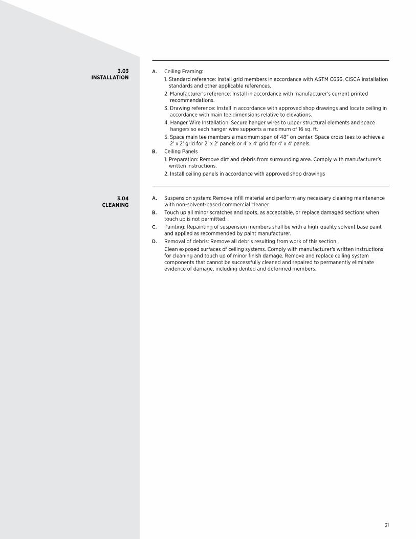
3.03 INSTALLATION
3.04 CLEANING
A. Ceiling Framing: 1. Standard reference: Install grid members in accordance with ASTM C636, CISCA installation
standards and other applicable references. 2. Manufacturer's reference: Install in accordance with manufacturer's current printed
recommendations. 3. Drawing reference: Install in accordance with approved shop drawings and locate ceiling in
accordance with main tee dimensions relative to elevations. 4. Hanger Wire Installation: Secure hanger wires to upper structural elements and space
hangers so each hanger wire supports a maximum of 16 sq. ft. 5. Space main tee members a maximum span of 48" on center. Space cross tees to achieve a
2' x 2' grid for 2' x 2' panels or 4' x 4' grid for 4' x 4' panels.B. Ceiling Panels 1. Preparation: Remove dirt and debris from surrounding area. Comply with manufacturer's
written instructions. 2. Install ceiling panels in accordance with approved shop drawings
A. Suspension system: Remove infill material and perform any necessary cleaning maintenance with non-solvent-based commercial cleaner.
B. Touch up all minor scratches and spots, as acceptable, or replace damaged sections when touch up is not permitted.
C. Painting: Repainting of suspension members shall be with a high-quality solvent base paint and applied as recommended by paint manufacturer.
D. Removal of debris: Remove all debris resulting from work of this section. Clean exposed surfaces of ceiling systems. Comply with manufacturer's written instructions
for cleaning and touch up of minor finish damage. Remove and replace ceiling system components that cannot be successfully cleaned and repaired to permanently eliminate evidence of damage, including dented and deformed members.

PRODUCT INFORMATIONSee usg.com for the most up-to-date product information.
CUSTOMER SERVICE800 950-3839
TECHNICAL SERVICE800 USG.4YOU (874-4968)usg.com
PRODUCT LITERATUREData Sheet IC561
LIMITATIONSInterior applications only
NOTICEWe shall not be liable for incidental and consequential damages, directly or indirectly sustained, nor for any loss caused by application of these goods not in accordance with current printed instructions or for other than the intended use. Our liability is expressly limited to replacement of defective goods. Any claim shall be deemed waived unless made in writing to us within thirty (30) days from date it was or reasonably should have been discovered.
SAFETY FIRST! Follow good safety/industrial hygiene practices during installation. Wear appropriate personal protective equipment. Read SDS and literature before specification and installation.
IC561/rev. 12-15 © 2015 USG Corporation and/or its affiliates. All rights reserved. Printed in U.S.A.The trademarks USG, ACOUSTIBOND, CENTRICITEE, COMPÄSSO, DONN, DX, DXI, DXF, DXFF, DXL, DXLT, DXT, FINELINE, TRUE WOOD, IT’S YOUR WORLD. BUILD IT., The USG logo, the design elements and colors, and related marks are trademarks of USG Corporation or its affiliates.