Embed Size (px)
Citation preview
TS01E - Deformation Monitoring – paper no. 5229 Maricel Palamariu and Mircea Puscas Using Engineering Survey Techniques for the Tonkolili Railways Project FIG Working Week 2011 Bridging the Gap between Cultures Marrakech, Morocco, 18-22 May 2011
1/16
Using Engineering Survey Techniques for the Tonkolili Railways Project
Maricel PALAMARIU and Mircea PUSCAS, Romania
Key words: Sierra Leone, rail way, design, stake out, EGM96, UTM SUMMARY
Tonkolili Railways Project is the biggest development project in Sierra Leone since the end of the civil war 10 years ago. It is the construction of 120 km of new railway from Lunsar to Tonkolili council. Three companies are principal contractors, Dawnus, Basil Reed and WBHO with AML being the principal client. The rail will be used to transport the iron ore from Tonkolili to Pepel port. The survey operations were taken two stages:
- First stage when the surveyors went on field to stake out the center line of the new rail. An autonomous position was used to stake out the coordinates, and a D6 Cat dozer to cut through the vegetation growth.
- Second stage – multiple surveys and stake out operations involved in construction. Establishing GPS control points and office post processing, original survey and stake out. Calculate and stake out alignment (horizontal and vertical), with straight, transitions and curves. Also calculate top of batter cut positions and toe of batter fill positions with slope distances and fill heights. A complete cross section survey every 20m taken at the start of the job and a weekly survey taken at work locations as job progressed. Volumes calculated from these surveys. The main problems have been to establish new control points in the desired map projections and geoid model.
I work for Dawnus, a Welsh civil engineering company, responsible for 50Km of new rail construction and 70Km of rail refurbishment. The engineers are all British and the surveyors are from Romania, who work closely together with Sierra Leone engineers. So there is three quite different cultures that mix together and have to make it work for the project to be a success.
Many villages have to be passed and everyday the surveyors got involved with local people. So again there is a big mix of cultures and sometimes the challenge can be difficult, but most of the time it is worthwhile.

TS01E - Deformation Monitoring – paper no. 5229 Maricel Palamariu and Mircea Puscas Using Engineering Survey Techniques for the Tonkolili Railways Project FIG Working Week 2011 Bridging the Gap between Cultures Marrakech, Morocco, 18-22 May 2011
2/16
Using Engineering Survey Techniques for the Tonkolili Railways Project
Maricel PALAMARIU and Mircea PUSCAS, Romania 1. INTRODUCTION 1.1 Scope of Work
African Minerals (AML) are planning to begin mining operations at their Tonkolili mine in North East of Sierra Leone during early 2010. The initial development of the AML railway/operations includes the rehabilitation of an open access Cape gauge (1067mm) rail line and port site at Pepel Port. This is the first open access railway in Sierra Leone. The last train was loaded and ran on this railway in 1985.
Initially, the iron ore will be hauled by road to a stock pile location close to but west of the town of Lunsar which will allow a connection to the previously used Cape gauge (1067mm) railway which ran from Marampa to the Port of Pepel in Sierra Leone. The iron ore will be loaded into open top and bottom dump iron ore wagons for the rest of the journey to the port, a distance of approximately 76 km.
While using this railway, it is also planned to construct and operate a heavy haul standard gauge railway (1436mm) of approximate distance of 210 km from the mine at Tonkolili to the new port at Tagrin in Sierra Leone with the capacity of 40 tonne axle loading with annual haulage rate of plus 50 million tonne per year. The final goal of these projects would be:
- Bulk Earthworks construction for the proposed railway alignment from Lunsar (0 km) to the mine at Tonkolili (approximately 125 km). This section covers all work in connection with the construction of cuts and fills, the removal to spoil of material unsuitable for use, the construction and compaction of bulk fills with cut material from the road way prism or borrow material from approved borrow pits, the compaction of the bulk earthworks and finishing off cuts and fills, up to the stage where the fills are ready for construction of the layer works.
- Structural Layer works construction for the proposed railway alignment from Lunsar to the mine at Tonkolili. This section covers all work in connection with the construction and compaction of the structural layer works, with approved cut material (suitably processed) from the road prism or borrow material from approved borrow pits, up to the stage where the fills are ready for placing the ballast layer.
- Supply, stake out and Installation of drainage culverts for the proposed railway alignment.
- Construction of stone pitch lined side drains (Immediate works only); - The setting out of Cut Off Drains and Banks on top of cuttings for Community
Projects; - Supply and Stockpiling of ballast stone.
TS01E - Deformation Monitoring – paper no. 5229 Maricel Palamariu and Mircea Puscas Using Engineering Survey Techniques for the Tonkolili Railways Project FIG Working Week 2011 Bridging the Gap between Cultures Marrakech, Morocco, 18-22 May 2011
3/16
Due to the size of the project and the specified time frame, the earth work has been divided into three work packages as follows: Work Package A: Construction of the earth works from km 0 to the bridge at km 50 Work Package B: Construction of the earth works from the bridge at km 50 to km 85 Work Package C: Construction of the earth works from km 85 to the Tonkolili mine, inclusive the tail track and ore load out loop.
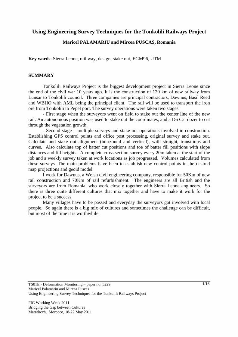
Also, Africa Minerals is in the process of refurbishing their Iron Ore port at Pepel, Sierra Leone. Pepel Stockyyard is situated near Pepel, Northern Province Sierra Leone, Western Africa. Pepel is at the North Eastern end of Freetown Harbour, on Atlantic seaboard, located near the mouth of the Sierra Leone River, an estuary formed by the Rokel River with Port Loko Creek.
Figure 1 - Project development throughout the country
The scope of works at Pepel, was the construction of all Civil Works pertaining to a
new Train dump station, conveying and stockpile system. The operations described in this section will refer to surveying for the setting out all the restricted earthworks and Civil Engineering work.
In this paper we will only refer to the topographic operations conducted for the construction of the railway between km 0 and km 50. The topographic operations performed in order to stake out the constructions and the auxiliary installations necessary for storing and loading iron ore from port Pepel will also be described. 1.2 Geodetic parameters
An original survey was done in 2009 year using Lidar techniques. This was done in order to obtain information about the terrain (Natural Ground Level – NGL) in order to accomplish the execution project.
The projection system used was UTM on the WGS84 ellipsoid. The survey area is
TS01E - Deformation Monitoring – paper no. 5229 Maricel Palamariu and Mircea Puscas Using Engineering Survey Techniques for the Tonkolili Railways Project FIG Working Week 2011 Bridging the Gap between Cultures Marrakech, Morocco, 18-22 May 2011
4/16
split between UTM zone 28 and UTM zone 29. The UTM28 and UTM29 parameters are as follows:
Name UTM Z28 Zone Number 28 Central Meridian 15° 00' 00.00000" W Hemisphere Northern
Name UTM Z29 Zone Number 29 Central Meridian 9° 00' 00.00000" W Hemisphere Northern
The WGS84 ellipsoid parameters are as follows:
Name WGS84Semi-major axis (a) 6378137.0Reciprocal Flattening (1/f) 298.257223563
The geoid model approved and used was EGM96. For commercial reasons, no
information about the geodetic equipment used will be provided. 2. PHASE ONE – PATH FINDER
Once the contractual obligations were fulfilled, the field work started. In the first phase, the designer provided the coordinates of the railway axis points, 50 meters centres along the alignment.
The first emergency was to stake out the railway axis and to clear the route from vegetation.
The stake out method used was the RTK method, using two geodetic receivers with dual frequency, and RTK capability. No information was provided on geodetic control points and also no topographic work done in the past could be identified. Because of this, to start the vegetation clearing procedures, a control point obtain by autonomous observations was used.
The work started approximately at km 14, where a site organization was placed. A team of surveyors were staking out the route, as the D6 bulldozer was clearing the vegetation.
The team was comprised of: An engineer from Wales, An engineer from Sierra Leone and Two local workers.
As the team was moving away from the first point, more control point were necessary to have radio coverage. The points were obtained through the RTK method, the precision being sufficient for their purpose.
The operations started March 2010 and continued until the end of the year. 3. PHASE TWO – DESIGN AND STAKE OUT 3.1 The design
At the end of September 2010, the designer provided information about the geometry of the railway axis. The axis geometry was provided as follows:

TS01E - Deformation Monitoring – paper no. 5229 Maricel Palamariu and Mircea Puscas Using Engineering Survey Techniques for the Tonkolili Railways Project FIG Working Week 2011 Bridging the Gap between Cultures Marrakech, Morocco, 18-22 May 2011
5/16
- The horizontal pozition of the axis was described by: Planimetric coordinates of the curve peaks, The lenght of the alignments, The radius of the connecting curves and The lenght of the transition curves.
Figure 2 - The horizontal geometric elements of the axis
- The horizontal pozition of the axis was described by: The length of the alignments, The tilt of the alignments, The elements on the vertical of the curves.
Figure 3 - The vertical geometric elements of the axis Of course, these elements couldn’t be used to stake out the railway axis. The geometric elements had to be used to obtain the coordinates of points on the axis of the railway. For this the functions of AutoCAD Civil3D were used. The order of the operations was the following:
- The coordinates of the curve peaks were reported in the software - The alignments were drawn - The elements of the connection curves and transition curves were inserted - The elements of the vertical profile were inserted - The chosen interval was 20m
TS01E - Deformation Monitoring – paper no. 5229 Maricel Palamariu and Mircea Puscas Using Engineering Survey Techniques for the Tonkolili Railways Project FIG Working Week 2011 Bridging the Gap between Cultures Marrakech, Morocco, 18-22 May 2011
6/16
The result of these calculations were the x,y,z coordinates of the points that define the railway axis, at a 20m interval. The coordinates were exported in a .csv format, containing the mileage, respectively the coordinates of the point, at that kilometre. 3.2 Control points It was obvious that the coordinates of the control points that came from autonomic determinations could not be used for the stakeout of the points. Even if theoretically a network could be developed from these coordinates, their use would make the connection of the three mentioned railway sections impossible. Therefore it was necessary to develop a network of control points to ensure homogeneity of the points for the whole project, starting from Pepel, and finishing at Tonkolili. The task of developing these networks fell in the beneficiary’s hands and it was done in two campaigns:
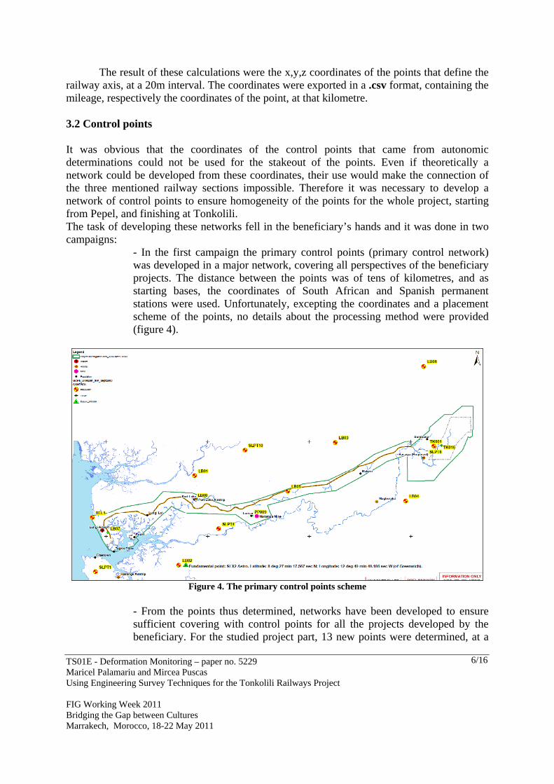
- In the first campaign the primary control points (primary control network) was developed in a major network, covering all perspectives of the beneficiary projects. The distance between the points was of tens of kilometres, and as starting bases, the coordinates of South African and Spanish permanent stations were used. Unfortunately, excepting the coordinates and a placement scheme of the points, no details about the processing method were provided (figure 4).
Figure 4. The primary control points scheme
- From the points thus determined, networks have been developed to ensure sufficient covering with control points for all the projects developed by the beneficiary. For the studied project part, 13 new points were determined, at a
TS01E - Deformation Monitoring – paper no. 5229 Maricel Palamariu and Mircea Puscas Using Engineering Survey Techniques for the Tonkolili Railways Project FIG Working Week 2011 Bridging the Gap between Cultures Marrakech, Morocco, 18-22 May 2011
7/16
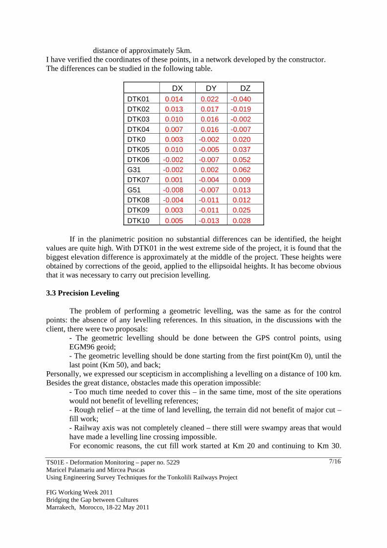
distance of approximately 5km. I have verified the coordinates of these points, in a network developed by the constructor. The differences can be studied in the following table.
DX DY DZ DTK01 0.014 0.022 -0.040
DTK02 0.013 0.017 -0.019
DTK03 0.010 0.016 -0.002
DTK04 0.007 0.016 -0.007
DTK0 0.003 -0.002 0.020
DTK05 0.010 -0.005 0.037
DTK06 -0.002 -0.007 0.052
G31 -0.002 0.002 0.062
DTK07 0.001 -0.004 0.009
G51 -0.008 -0.007 0.013
DTK08 -0.004 -0.011 0.012
DTK09 0.003 -0.011 0.025
DTK10 0.005 -0.013 0.028 If in the planimetric position no substantial differences can be identified, the height
values are quite high. With DTK01 in the west extreme side of the project, it is found that the biggest elevation difference is approximately at the middle of the project. These heights were obtained by corrections of the geoid, applied to the ellipsoidal heights. It has become obvious that it was necessary to carry out precision levelling.
3.3 Precision Leveling
The problem of performing a geometric levelling, was the same as for the control points: the absence of any levelling references. In this situation, in the discussions with the client, there were two proposals:
- The geometric levelling should be done between the GPS control points, using EGM96 geoid; - The geometric levelling should be done starting from the first point(Km 0), until the last point (Km 50), and back;
Personally, we expressed our scepticism in accomplishing a levelling on a distance of 100 km. Besides the great distance, obstacles made this operation impossible:
- Too much time needed to cover this – in the same time, most of the site operations would not benefit of levelling references; - Rough relief – at the time of land levelling, the terrain did not benefit of major cut – fill work; - Railway axis was not completely cleaned – there still were swampy areas that would have made a levelling line crossing impossible. For economic reasons, the cut fill work started at Km 20 and continuing to Km 30.

TS01E - Deformation Monitoring – paper no. 5229 Maricel Palamariu and Mircea Puscas Using Engineering Survey Techniques for the Tonkolili Railways Project FIG Working Week 2011 Bridging the Gap between Cultures Marrakech, Morocco, 18-22 May 2011
8/16
GPS control points from the area were DTK06, G31 and DTK07. So we decided performing the following levelling routes:
- DTK06 – G31 - G31 – DTK07. The levelling was done using a level with an accuracy of 0.2 mm, with a double
horizon. Between the control points, new points were placed (bench marks), for which it was intended to determine the planimetric coordinates and the height. The height, of the GPS control points were used. The results were surprising. First of all, the differences between the two horizons did not exceed 3 mm. Height errors were of tens of milimeters. DTK07 1.5620 30.2600 71.5900 9074.0700 -0.6328 72.979 73.027 [dH]= 1.6495 Wh= 0.0485 Tolerance 0.0301
As we can see, on a length of 9074 m, the error was 48 mm. It isn’t a big value in the given conditions. But compensating this levelling line, and checking the value obtained in G31, it was found that the height from the levelling it is very close to the GPS height, obtained in GPS network, done by the contractor. Therefore we performed a new calculation, this time using the height values obtained by our processing. The result can be studied below. DTK07 1.5620 30.2600 71.5900 9074.0700 -0.6328 73.024 73.027 [dH]= 1.6495 Wh= 0.0035 Tolerance 0.0301
The result is surprising, and the control done in G31, showed a difference between the calculated height, and the GPS height, if 2,5 mm.
As already mentioned, on the levelling route, some new control points were made. To determine the coordinates of these points, a network of vectors were made, constrained on DTK06 and DTK07. To make the network, four L1/L2 geodetic receivers were used.
After GPS processing, also the heights of the points resulted, on EGM96 geoid model.
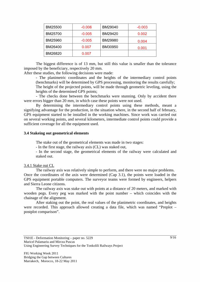
Differences obtained by geometric levelling and heights resulted from GPS processing, can be studied below:
BM23320 0.008 BM27620 -0.004
BM23580 0.010 BM27701 -0.013
BM23880 0.000 BM27900 -0.005
BM24120 -0.004 BM28160 -0.010
BM24880 -0.012 BM28580 -0.005
TS01E - Deformation Monitoring – paper no. 5229 Maricel Palamariu and Mircea Puscas Using Engineering Survey Techniques for the Tonkolili Railways Project FIG Working Week 2011 Bridging the Gap between Cultures Marrakech, Morocco, 18-22 May 2011
9/16
BM25500 -0.006 BM29040 -0.003
BM25700 -0.005 BM29420 0.002
BM25960 -0.005 BM29980 0.004
BM26400 0.007 BM30950 0.001
BM26820 0.007 The biggest difference is of 13 mm, but still this value is smaller than the tolerance
imposed by the beneficiary, respectively 20 mm. After these studies, the following decisions were made:
- The planimetric coordinates and the heights of the intermediary control points (benchmarks) will be determined by GPS processing, monitoring the results carefully; The height of the projected points, will be made through geometric leveling, using the heights of the determined GPS points; - The checks done between the benchmarks were stunning. Only by accident there
were errors bigger than 20 mm, in which case these points were not used. By determining the intermediary control points using these methods, meant a
signifying advantage for the production, in the situation where, in the second half of february, GPS equipment started to be installed in the working machines. Since work was carried out on several working points, and several kilometers, intermediate control points could provide a sufficient coverage for all the equipment used. 3.4 Stakeing out geometrical elements
The stake out of the geometrical elements was made in two stages: - In the first stage, the railway axis (CL) was staked out, - In the second stage, the geometrical elements of the railway were calculated and staked out.
3.4.1 Stake out CL
The railway axis was relatively simple to perform, and there were no major problems. Once the coordinates of the axis were determined (Cap 3.1), the points were loaded in the GPS equipment portable computers. The surveyor teams were formed by engineers, helpers and Sierra Leone citizens.
The railway axis was stake out with points at a distance of 20 meters, and marked with wooden pegs. Every peg was marked with the point number – which coincides with the chainage of the alignment.
After staking out the point, the real values of the planimetric coordinates, and heights were recorded. This approach allowed creating a data file, which was named “Preplot – postplot comparison”.
TS01E - Deformation Monitoring – paper no. 5229 Maricel Palamariu and Mircea Puscas Using Engineering Survey Techniques for the Tonkolili Railways Project FIG Working Week 2011 Bridging the Gap between Cultures Marrakech, Morocco, 18-22 May 2011
10/16
Design Stake out
Chainages E N h E N E dE dN dD dh
0 103298.947 966016.596 66.407 103298.949 966016.576 66.307 -0.002 0.020 0.020 0.100
20 103313.361 966002.732 66.480 103313.372 966002.724 66.402 -0.011 0.008 0.014 0.078
40 103327.461 965988.548 66.539 103327.421 965988.563 66.476 0.040 -0.015 0.043 0.063
60 103341.448 965974.252 66.584 103341.441 965974.224 66.511 0.007 0.028 0.029 0.073
80 103355.429 965959.952 66.615 103355.421 965959.924 66.582 0.008 0.028 0.029 0.033
100 103369.411 965945.651 66.632 103369.387 965945.695 66.538 0.024 -0.044 0.050 0.094
120 103383.392 965931.350 66.636 103383.378 965931.351 66.532 0.014 -0.001 0.014 0.104
140 103397.374 965917.049 66.628 103397.322 965917.042 66.565 0.052 0.007 0.052 0.063
160 103411.356 965902.748 66.612 103411.349 965902.760 66.585 0.007 -0.012 0.014 0.027
180 103425.337 965888.447 66.587 103425.338 965888.462 66.574 -0.001 -0.015 0.015 0.013
200 103439.319 965874.146 66.554 103439.289 965874.155 66.576 0.030 -0.009 0.031 -0.022
220 103453.300 965859.846 66.513 103453.287 965859.861 66.550 0.013 -0.015 0.020 -0.037
240 103467.282 965845.545 66.463 103467.299 965845.569 66.563 -0.017 -0.024 0.029 -0.100
260 103481.264 965831.244 66.405 103481.252 965831.216 66.558 0.012 0.028 0.030 -0.153
280 103495.245 965816.943 66.339 103495.222 965816.936 66.432 0.023 0.007 0.024 -0.093
300 103509.227 965802.642 66.269 103509.260 965802.643 66.430 -0.033 -0.001 0.033 -0.161
320 103523.208 965788.341 66.200 103523.216 965788.337 66.397 -0.008 0.004 0.009 -0.197
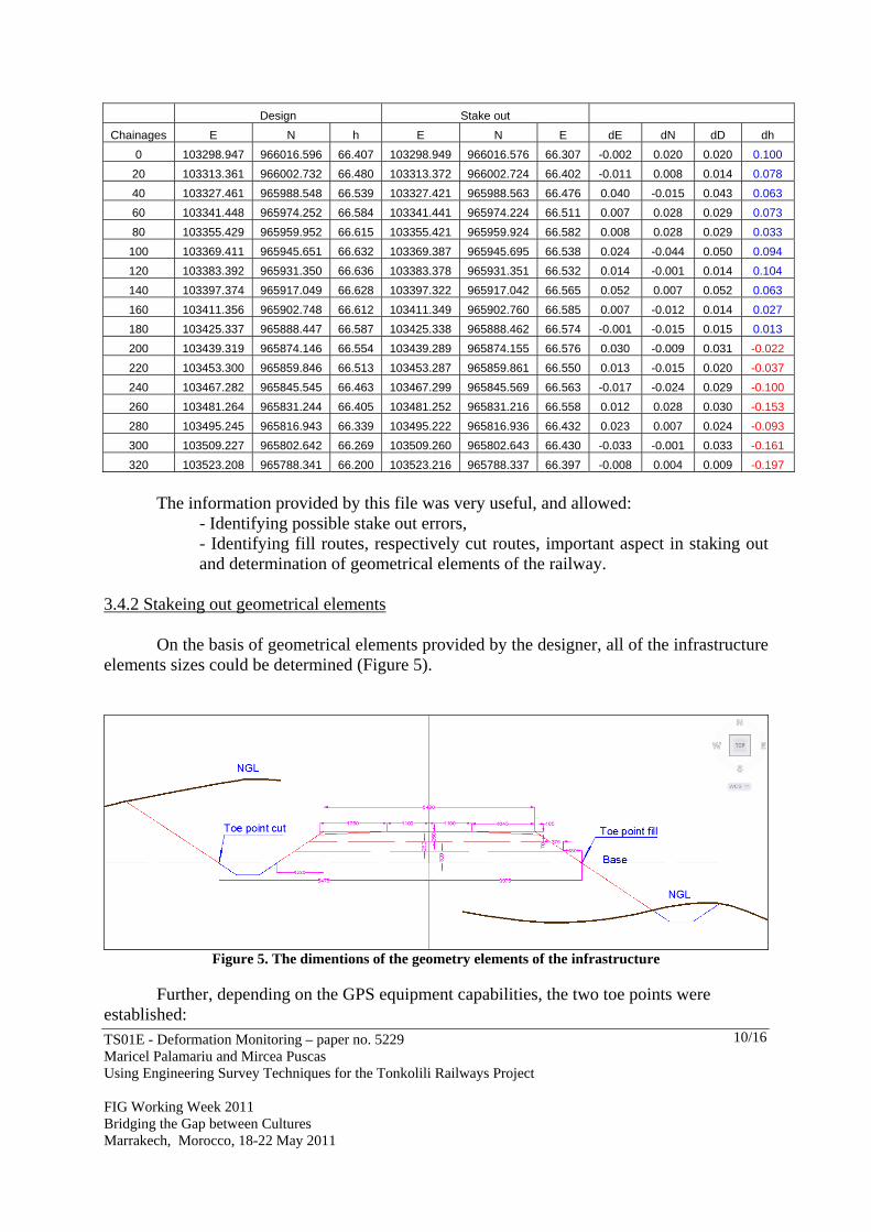
The information provided by this file was very useful, and allowed:
- Identifying possible stake out errors, - Identifying fill routes, respectively cut routes, important aspect in staking out and determination of geometrical elements of the railway.
3.4.2 Stakeing out geometrical elements
On the basis of geometrical elements provided by the designer, all of the infrastructure elements sizes could be determined (Figure 5).
Figure 5. The dimentions of the geometry elements of the infrastructure
Further, depending on the GPS equipment capabilities, the two toe points were
established:

TS01E - Deformation Monitoring – paper no. 5229 Maricel Palamariu and Mircea Puscas Using Engineering Survey Techniques for the Tonkolili Railways Project FIG Working Week 2011 Bridging the Gap between Cultures Marrakech, Morocco, 18-22 May 2011
11/16
- Infrastucture basis for fill – distance from axis of 3975 mm, - Embankment basis for cut – distance from axis of 5475 mm. From the file specified in Chapter 3.4.1, the points that were in fill, respectively the
points that were in cut could be determined exactly. Lists were made for all the determined points, with the left – right distance values
from the railway axis. Next, the coordinates of all left – right toe points were determined. The coordinates were determined using AutoCad’s Civil3D special functions – respectively offset – points functions.
The coordinates thus obtained were loaded in portable computers and began staking them out. The information obtained was different from cut (or fill) and the distance until the respective toe point. With a pocket calculator, these values were checked depending on the embankment projected slope (1:1.5) and establishing the position of the start point of the cut, respectively of the fill. These points were after materialized with special beacons according to known procedures.
It is worth mentioning that these dimensions were calculated both for the base geometry for the railway as well as for the layers that form the embankment. The determination of the x, y and z coordinates for all the points determined this way made it possible to create digital models for each project phase. The digital models were loaded in the GPS equipment – which led to an ease in stake out, as well as in the special equipment mounted on working vehicles. 3.5 Topographic operations done for staking out the installations and constructions from Port Pepel
As shown at the beginning of the project, AML started extensive work for redeveloping the loading installations of the iron ore in wagons. The constructions and installations mainly consisted of:
- A station for unloading iron ore from wagons; - A station for loading iron ore into ships; - A complex network of conveyor belts to ensure the transportation of the iron ore.
TS01E - Deformation Monitoring – paper no. 5229 Maricel Palamariu and Mircea Puscas Using Engineering Survey Techniques for the Tonkolili Railways Project FIG Working Week 2011 Bridging the Gap between Cultures Marrakech, Morocco, 18-22 May 2011
12/16
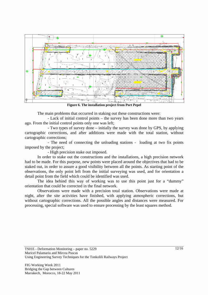
Figure 6. The installation project from Port Pepel
The main problems that occurred in staking out these constructions were:
- Lack of initial control points – the survey has been done more than two years ago. From the initial control points only one was left; - Two types of survey done – initially the survey was done by GPS, by applying cartographic corrections, and after additions were made with the total station, without cartographic corrections; - The need of connecting the unloading stations - loading at two fix points imposed by the project; - High precision stake out imposed.
In order to stake out the constructions and the installations, a high precision network had to be made. For this purpose, new points were placed around the objectives that had to be staked out, in order to assure a good visibility between all the points. As starting point of the observations, the only point left from the initial surveying was used, and for orientation a detail point from the field which could be identified was used.
The idea behind this way of working was to use this point just for a “dummy” orientation that could be corrected in the final network.
Observations were made with a precision total station. Observations were made at night, after the site activities have finished, with applying atmospheric corrections, but without cartographic corrections. All the possible angles and distances were measured. For processing, special software was used to ensure processing by the least squares method.

TS01E - Deformation Monitoring – paper no. 5229 Maricel Palamariu and Mircea Puscas Using Engineering Survey Techniques for the Tonkolili Railways Project FIG Working Week 2011 Bridging the Gap between Cultures Marrakech, Morocco, 18-22 May 2011
13/16
Figure 7. The coordinates and the corrections of the new points determined in Port Pepel.
As can be seen, the biggest errors were noticed at the most distant points of the
network (Pepel7 and Pepel3), but all errors were below 5mm, below the tolerance imposed at the stake out. 3.6 Other topographic operations
The operations specified in the previous chapters, were not the only topographical operations done. With a huge volume of construction, every day new problems occured that required the intervention of the surveyors: Relocation of control points, Relocation of beacons, Stake out and heigh checking, Weekly production survey, Calculation of volumes etc.
Very spectacular 3D models of some locations were created, so calculation of volumes was could be carried out. Special surveys for the creation of 3D models were done at the two stone quarries – Rofayne and Mackeri.
Creating these models allowed developing different exploit methods and precise monitoring of the exploited rock quantities. 4. CONCLUSIONS AND SUGGESTIONS
This paper’s goal was to highlight the steps completed in the stake out of a large scale investment project.
As already mentioned, the construction of these 50 kilometers of railway interposed between the existence of an old railway and the construction of the new section (another by a construction firm). The main challenge in accomplishing this work was the precision of the connection between the sections. The described work led to the following results:
- At km 0, the connection precision with the existent section was of 10 mm, - At km 50, the connection precision with the next section (on common control points) was
of 5 mm.

TS01E - Deformation Monitoring – paper no. 5229 Maricel Palamariu and Mircea Puscas Using Engineering Survey Techniques for the Tonkolili Railways Project FIG Working Week 2011 Bridging the Gap between Cultures Marrakech, Morocco, 18-22 May 2011
14/16
This was done without any compensation measurements. Worth mentioning is the fact that the connection precision with the other section was over 200 mm, that imposed compensation operations. The main problem identified throughout the project was the lack of an adequate cartographic projection. Sierra Leone is crossed by two UTM zones, Zone 28 and zone 29. All the work was done on zone 29, which led to quite big cartographic deformations.
Figure 8. UTM projection and the proposal of stereographic projection for Sierra Leone
For infrastructure projects, the UTM projection isn’t quite adequate. Taking into
account the shape of the country, a plane projection, stereographic, with the center of projection in the middle of the country - 12°W and 8°30’N , this option should be considered. The null deformations circle should have an approximate 80-90 km diameter. Such a projection would ensure the homogeneity of all topographical surveys throughout the country, for all the future projects.
However, the coordinates of all involved points are known in geographical coordinates, so their transformation to a new projection should not be a problem.
Even in ideal circumstances – the existence of control points for planimetric positioning and height, the existence of an adequate projection system, accomplishing this kind of project would have been a challenge. The lack of previous surveys (cartographic projection, geodetical points, levelling references, etc.), a relatively low experience for this kind of projects in countries like Sierra Leone, made accomplishing this project, a challenge for all employees, both from the Contractor as well as the Beneficiary.
The teams that helped accomplishing this project were composed of engineers from Wales, surveyors from Romania, and engineers from Sierra Leone.

TS01E - Deformation Monitoring – paper no. 5229 Maricel Palamariu and Mircea Puscas Using Engineering Survey Techniques for the Tonkolili Railways Project FIG Working Week 2011 Bridging the Gap between Cultures Marrakech, Morocco, 18-22 May 2011
15/16
The problems occurred daily, but perseverance, contributed to a great team. The experience of Wales engineers, with the technical knowledge of Romanian surveyors, and the help received from local engineers and the interference with the local culture, have led to great enthusiasm in the execution of the project.
Even with the mentioned obstacles, Dawnus firm’s team of engineers demonstrated knowledge and sufficient skills for accomplishing a project of this size.
Recognition of technical skills came from the employer too – AML, by entrusting the second phase of the project, namely building a new railway of about 90 km.
I would like to give my sincere thanks to the following people, with whose help I would not have been able to complete this paper: Mr. Andy Peters – Project Director Mr. Mike Condon – Project Manager A special mention also to my Welsh colleagues for their help and assistance: Mr. Andrew Pope, Mr. Ian St. Jhon, Mr. Gerrant Eduard, Mr. Richard Samuel My thanks and appreciation to my staff from Sierra Leone for all their hard work: Mr. Prince Tucker, Mr. Ibrahim Sano,
Mr. Vidal Kay, Mr. Musa Koroma
And, not on the last sincere thanks to my Romanian collegues for all their help: Mr. Sergiu Vaida,
Mr. Alex Pop, Mr. Paul Cristea

TS01E - Deformation Monitoring – paper no. 5229 Maricel Palamariu and Mircea Puscas Using Engineering Survey Techniques for the Tonkolili Railways Project FIG Working Week 2011 Bridging the Gap between Cultures Marrakech, Morocco, 18-22 May 2011
16/16
REFERENCES 1- Blais J.A.R.: Optimal Modelling for the Revision of Positional Data in Spatial Information Systems, CISM Journal ACSGC, 44(2):113-121, 1990 2.-Boş, N., 2007, Modern Topography, C.H. Beck, Bucharest 3-Bugayevsky Lev M., John P. Snyder, Map Projections, A Reference Manual, Taylor & Francis Ltd, 4 John St, London WC1N 2ET 1995 4-Dragomir, P.I., Rus, T., Dumitru, P., 2005, Modernisation of the Romanian GPS network, Geodesic, Geodesic and cartographic paper nr. 1-2 Bucharest 5- Hofmann-Wellenhof B., Lichtenegger H. and Collins J.: Global Positioning System, Springer-Verlag Wien New York, 1992 6-Nistor Gh., Nistor I., Direct Algorithm for the Calculation of Vertical Displacements and Deformations of Constructions Using High–Precision Geometric Leveling, RevCAD – Journal of Geodesy and Cadastre, no.7,Alba Iulia, 2007. 7- Palamariu M., V. Buda, A. R. Iancu-,The use of digital elevation models in generating real - time 3D environments: a case study, RevCAD –Journal of Geodesy and Cadastre no.9 ,Alba Iulia, 2009 pg. 167 8- Poder K. and Hornik H.: The European Datum 1989, Retrig Publication No. 18, 1989 9- Richard K. Burkard: Geodesy for the Layman, U.S. Department of Commerce, National Oceanic and Admospheric Administration, 1983 10- Snyder P. John, Map Projections, A Working Manual, US Government Printing Office, Washington 1987. 11- Coordinate Conversion and Transformations including Formulas, OGP Surveying and Positioning Guidance Note number 7, part 2 – April 2006 12- ISO 19111 Spatial referencing by coordinates, International Organization for Standardization, 2003 13- Map Projections for Europe, Edited by: A. Annoni, C. Luzet, E. Gubler and J. Ihde, Joint Research Centre of European Commission, EuroGeographics, Italy, 2001 14-Ordnance Survey: The Impact of the Global Positioning System on NationalMapping Policy. Consultative Paper No 2, Ordnance Survey, Southampton, UK, 1992 CONTACTS
Professor Maricel Palamariu, "1 December 1918" University of Alba Iulia Romania 28, Detunata street, bl. D5, sc. C, ap. 3 Alba Iulia, 510064 Romania Tel. 0040723148556 Fax 0040258812630 Email [email protected] Web site: www.uab.ro
Lect. Eng. Simion Mircea Puscas University of Agricultural Sciences Cluj-Napoca, Cluj Napoca, Romania Dawnus Construction Ltd. 7 Dyffryn Court, Riverside Business Park Swansea, SA7 0AP UK Tel. +40745656909 Fax + 441792787867 Email: [email protected] Web site: www.dawnus.co.uk