Embed Size (px)
Citation preview

Using the RealSense D4xx Depth Sensors in Multi-Camera Configurations
Anders Grunnet-Jepsen, Paul Winer, Aki Takagi, John Sweetser, Kevin Zhao, Tri Khuong, Dan Nie, John Woodfill
Rev 0.4
There are a number of reasons for wanting to combine multiple depth sensors for simultaneous live capture
of scenes. For one, arranging depth sensors in an inward-facing configuration will allow for the simultaneous
capture of both the front and back of objects, so that the real-time, whole surface volumes of objects can
be captured. This 3D recording can be used, for example, for Virtual- or Augmented-Reality “teleportation”
and teleconferencing. Alternatively, arranging depth sensors in an outward-facing configuration will create
a depth sensor system that has a much wider field-of-view (FOV), and can be used to capture both forward
and backward facing depth. This composite FOV configuration is desirable for autonomous robots, drones
and vehicles, as well as for security systems that need to continuously analyze a wide surrounding area.
From a technology perspective, these and many more configurations are permissible for the RealSense
D4xx series of depth cameras because they do not suffer from any significant cross-talk when the depth
sensors overlap in field-of-view, and they can all be hardware synchronized to capture at identical times
and frame rates. In this paper, we look at all the factors that need to be considered when connecting up
many RealSense 3D Cameras, as well as answering the question: “How many cameras can I connect?”
In the following analysis we examine connecting four D415 RealSense Depth Cameras together in the
outward facing configuration. We focus our attention on capturing and displaying depth as well as the left-
color channel for a system where the cameras are mounted vertically in a half-ring, as shown in the lower
middle picture above, and connected to an Intel Skull-Canyon NUC PC (with Intel i7-6700HQ Quad Core
Processor 2.6GHz up to 3.5GHz). Since each camera has an FOV of about 68x42 degrees, the combined
FOV is 68 vertical by 162 degrees horizontal, as we allow for a couple of degrees of overlap. Note that
since the FOVs do not originate from the exact same point in space, there will always be some non-
overlapping region as well, as illustrated below.

1. Connecting the cameras
Multiple cameras can be connected to a PC and will be able to stream independent data. The cameras
operate in the “Default” mode and will stream asynchronously. However, if it is desired to hardware
synchronize (e.g. HW sync) them so they capture at exactly the same time and rate, the cameras will
need to be connected via sync cables, and will need to be configured in software to have a single
master (or an externally generated sync signal) and multiple slaves. The connector port can be found
on the cameras as shown below, and a cable will need to be assembled.
The connector has manufacture part number ASSHSSH28K152, and the housing has part number
SHR-09V-S-B. The parts can be purchased at Digikey:
https://www.digikey.com/product-detail/en/jst-sales-america-inc/SHR-09V-S/455-1399-ND/759888
https://www.digikey.com/product-detail/en/jst-sales-america-inc/SSH-003T-P0.2/455-1561-1-
ND/720818
https://www.digikey.com/product-detail/en/jst-sales-america-inc/ASSHSSH28K305/455-3077-
ND/6009453
For HW sync, pins 5 (SYNC) and pins 9 (Ground) need to be connected as shown below. To connect
multiple cameras, you can daisy-chain or use a star-configuration. ESD protection, noise filtering, and
shielded cables may be needed.

2. Multi-camera considerations:
Multiple cameras can be connected together, but exactly how many depends on numerous factors
which will be discussed here. We start by sharing our experiences and then diving into more detail for
those who want to explore pushing the limits further. We show two tables below. The first uses a 4-port
powered USB3 hub (AmazonBasics), and the other has all USB cables connected straight to the NUC
PC. The green cells indicate that streaming has been verified successfully, while the yellow means
slightly reduced frame rate (i.e. some dropped frames), the red means less than half-frame rate or
none, and grey is “not tested”.
Streaming Results for 4-port USB3 hub with HW sync enabled:
Streaming Results for connecting directly to 4 ports of a PC with HW sync enabled:
Single HUB
Mode Bandwidth, Mbps 1 unit 2 units 3 units 4 units 5 units 6 units
Depth: 848x480, 90fps +
Left Color: 848x480, 90fps 1172 1172 2345 3517 4689 5861 7034
Depth: 1280x720, 30fps +
Left Color: RGB 1280x720, 30fps 885 885 1769 2654 3539 4424 5308
Depth: 1280x720, 30fps +
Left Mono: RGB 1280x720, 30fps 664 664 1327 1991 2654 3318 3981
Depth-only: 848x480, 90fps 586 586 1172 1758 2345 2931 3517
Depth-only: 1280x720, 30fps 442 442 885 1327 1769 2212 2654
Depth: 840x480, 30fps +
Left Color: Mono 848x480, 30fps 293 293 586 879 1172 1465 1758
Depth: 640x360, 30fps +
Left Color: RGB 640x360, 30fps 221 221 442 664 885 1106 1327
Depth-only: 640x360, 30fps 111 111 221 332 442 553 664
Indivual USB connection (PC with multiple USB)
Mode Bandwidth, Mbps 1 unit 2 units 3 units 4 units 5 units 6 units
Depth: 848x480, 90fps +
Left Color: 848x480, 90fps 1172 1172 2345 3517 4689 5861 7034
Depth: 1280x720, 30fps +
Left Color: RGB 1280x720, 30fps 885 885 1769 2654 3539 4424 5308
Depth: 1280x720, 30fps +
Left Mono: RGB 1280x720, 30fps 664 664 1327 1991 2654 3318 3981
Depth-only: 848x480, 90fps 586 586 1172 1758 2345 2931 3517
Depth-only: 1280x720, 30fps 442 442 885 1327 1769 2212 2654
Depth: 840x480, 30fps +
Left Color: Mono 848x480, 30fps 293 293 586 879 1172 1465 1758
Depth: 640x360, 30fps +
Left Color: RGB 640x360, 30fps 221 221 442 664 885 1106 1327
Depth-only: 640x360, 30fps 111 111 221 332 442 553 664
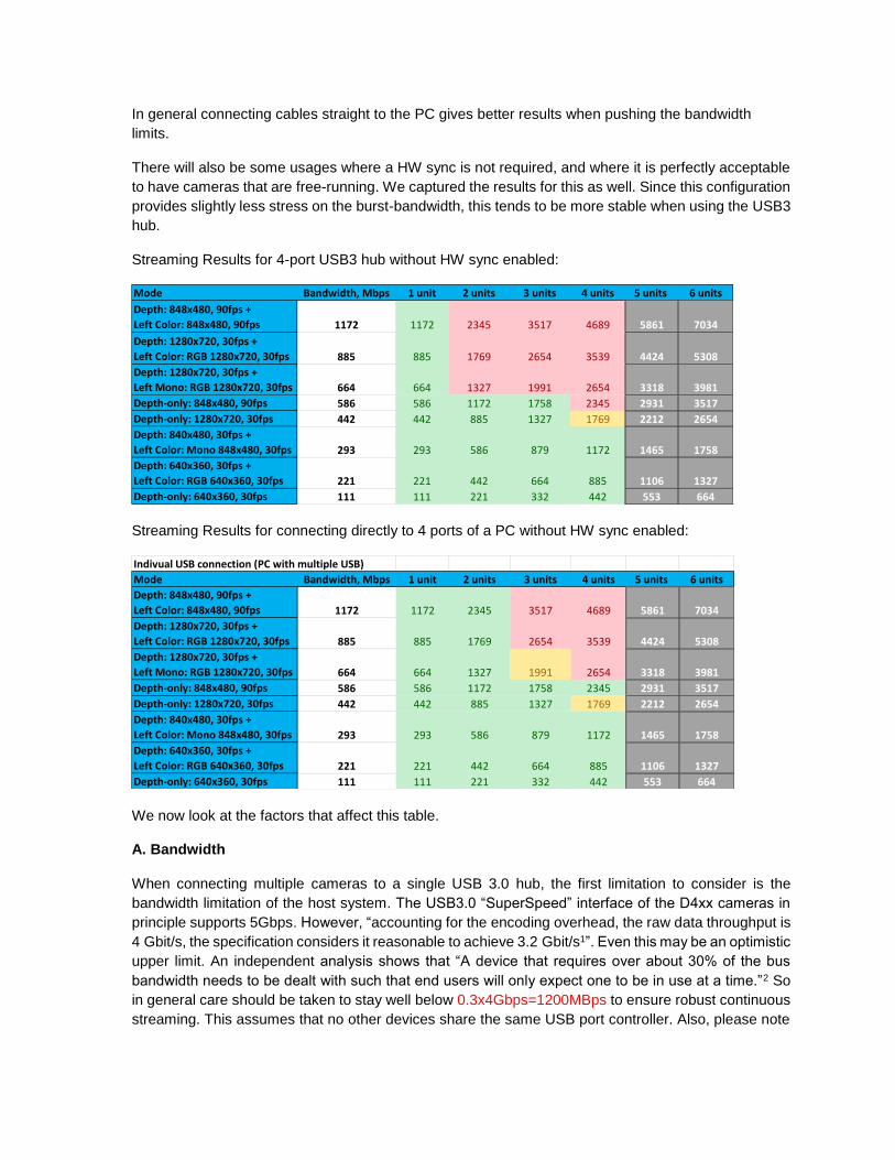
In general connecting cables straight to the PC gives better results when pushing the bandwidth
limits.
There will also be some usages where a HW sync is not required, and where it is perfectly acceptable
to have cameras that are free-running. We captured the results for this as well. Since this configuration
provides slightly less stress on the burst-bandwidth, this tends to be more stable when using the USB3
hub.
Streaming Results for 4-port USB3 hub without HW sync enabled:
Streaming Results for connecting directly to 4 ports of a PC without HW sync enabled:
We now look at the factors that affect this table.
A. Bandwidth
When connecting multiple cameras to a single USB 3.0 hub, the first limitation to consider is the
bandwidth limitation of the host system. The USB3.0 “SuperSpeed” interface of the D4xx cameras in
principle supports 5Gbps. However, “accounting for the encoding overhead, the raw data throughput is
4 Gbit/s, the specification considers it reasonable to achieve 3.2 Gbit/s1”. Even this may be an optimistic
upper limit. An independent analysis shows that “A device that requires over about 30% of the bus
bandwidth needs to be dealt with such that end users will only expect one to be in use at a time.”2 So
in general care should be taken to stay well below 0.3x4Gbps=1200MBps to ensure robust continuous
streaming. This assumes that no other devices share the same USB port controller. Also, please note
Mode Bandwidth, Mbps 1 unit 2 units 3 units 4 units 5 units 6 units
Depth: 848x480, 90fps +
Left Color: 848x480, 90fps 1172 1172 2345 3517 4689 5861 7034
Depth: 1280x720, 30fps +
Left Color: RGB 1280x720, 30fps 885 885 1769 2654 3539 4424 5308
Depth: 1280x720, 30fps +
Left Mono: RGB 1280x720, 30fps 664 664 1327 1991 2654 3318 3981
Depth-only: 848x480, 90fps 586 586 1172 1758 2345 2931 3517
Depth-only: 1280x720, 30fps 442 442 885 1327 1769 2212 2654
Depth: 840x480, 30fps +
Left Color: Mono 848x480, 30fps 293 293 586 879 1172 1465 1758
Depth: 640x360, 30fps +
Left Color: RGB 640x360, 30fps 221 221 442 664 885 1106 1327
Depth-only: 640x360, 30fps 111 111 221 332 442 553 664
Indivual USB connection (PC with multiple USB)
Mode Bandwidth, Mbps 1 unit 2 units 3 units 4 units 5 units 6 units
Depth: 848x480, 90fps +
Left Color: 848x480, 90fps 1172 1172 2345 3517 4689 5861 7034
Depth: 1280x720, 30fps +
Left Color: RGB 1280x720, 30fps 885 885 1769 2654 3539 4424 5308
Depth: 1280x720, 30fps +
Left Mono: RGB 1280x720, 30fps 664 664 1327 1991 2654 3318 3981
Depth-only: 848x480, 90fps 586 586 1172 1758 2345 2931 3517
Depth-only: 1280x720, 30fps 442 442 885 1327 1769 2212 2654
Depth: 840x480, 30fps +
Left Color: Mono 848x480, 30fps 293 293 586 879 1172 1465 1758
Depth: 640x360, 30fps +
Left Color: RGB 640x360, 30fps 221 221 442 664 885 1106 1327
Depth-only: 640x360, 30fps 111 111 221 332 442 553 664
that that while many computers will have multiple USB connectors, this is sometimes achieved by using
an internal USB hub as opposed to having multiple independent controllers.
Turning now to the RealSense D4xx cameras, the camera can operate in multiple modes. For best
depth performance it is generally recommended to operate the D415 at 1280x720, and the D430 at
848x480. Assuming 30fps and 16bit depth, this translates to 442Mbps, as per the tables above. To
transmit color at RGB at the same time, adds about 24x1280x720x30=663Mbps. However, by default
the ASIC is in YUYV mode which reduces the bandwidth by encoding the color in 16bits as opposed to
24bits, so the color channel is then 442Mbps.
This means that connecting 4x D415 and transmitting color and depth will consume 3539Mbps, which
as the table shows, is clearly not doable, while reducing the resolution to 640x360 shows no problem
streaming 4 channels of both color and depth as the total bandwidth is 882Mbps.
B. Power
The USB3 specification for is 900mA, or 4.5W. RealSense cameras perform all depth processing on
the on-board ASIC, and also control two or more cameras, as well as having the option to turn a laser
projector on at varying power. In general this means that the power consumption can approach or even
exceed 2W per camera. As such, a rule of thumb should be to make sure to use USB Hubs that support
external power supplies, or to use individual ports on a PC that provide independent power to the USB
spec. A powered HUB will normally provide 12.5W or more.
C. CPU
Attaching multiple cameras will also require processing power from the host system for reading the
USB ports, streaming the high-bandwidth data, and doing some amount of real-time post processing,
rendering, and analysis. When streaming high resolution color and depth, the processing requirements
quickly add up, and will impose another important limitation that needs to be considered. We will not
go into an extensive analysis of this here, except to say that care should be taken to select a computer
platform that supports the intended workload.
D. Cabling and enumeration
Another perhaps mundane consideration is the cabling. Unfortunately the quality of USB3.0 cables can
vary quite a bit. For best performance, we recommend using high quality cables and using as short
cables as possible - preferably less than 1m. If any bandwidth issues are observed, it can be good to
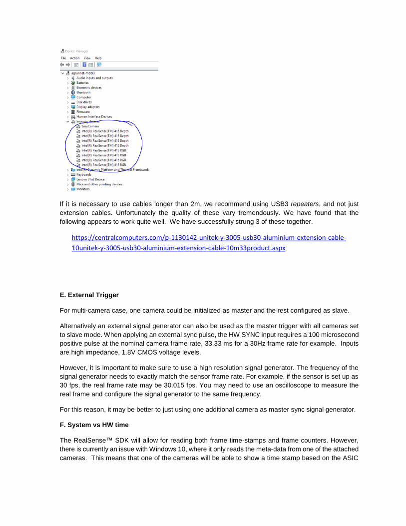
replace cables or shorten them to see whether this is the cause of the errors. It is also good to confirm
that the cameras are actually connected. A Windows 10 example is shown below. If all cameras are
not observed, try reconnecting them. If using an externally powered USB HUB, also make sure to
disconnect then reconnect power to the USB3 hub.
If it is necessary to use cables longer than 2m, we recommend using USB3 repeaters, and not just
extension cables. Unfortunately the quality of these vary tremendously. We have found that the
following appears to work quite well. We have successfully strung 3 of these together.
https://centralcomputers.com/p-1130142-unitek-y-3005-usb30-aluminium-extension-cable-
10unitek-y-3005-usb30-aluminium-extension-cable-10m33product.aspx
E. External Trigger
For multi-camera case, one camera could be initialized as master and the rest configured as slave.
Alternatively an external signal generator can also be used as the master trigger with all cameras set
to slave mode. When applying an external sync pulse, the HW SYNC input requires a 100 microsecond
positive pulse at the nominal camera frame rate, 33.33 ms for a 30Hz frame rate for example. Inputs
are high impedance, 1.8V CMOS voltage levels.
However, it is important to make sure to use a high resolution signal generator. The frequency of the
signal generator needs to exactly match the sensor frame rate. For example, if the sensor is set up as
30 fps, the real frame rate may be 30.015 fps. You may need to use an oscilloscope to measure the
real frame and configure the signal generator to the same frequency.
For this reason, it may be better to just using one additional camera as master sync signal generator.
F. System vs HW time
The RealSense™ SDK will allow for reading both frame time-stamps and frame counters. However,
there is currently an issue with Windows 10, where it only reads the meta-data from one of the attached
cameras. This means that one of the cameras will be able to show a time stamp based on the ASIC
“Hardware Clock”, while the other will default to the “System Time”. The time domain of an imager can
be queried using the following command:
rs2_timestamp_domain rs2_get_frame_timestamp_domain(const rs2_frame* frameset, rs2_error**
error);
To fix this issue, it is recommended to run the following script. This is required if the different cameras
are to be HW synchronized based on time-stamp or frame counters.
https://github.intel.com/PercHW/librealsense/blob/ds5_new/doc/installation_windows.md#use-
automation-script
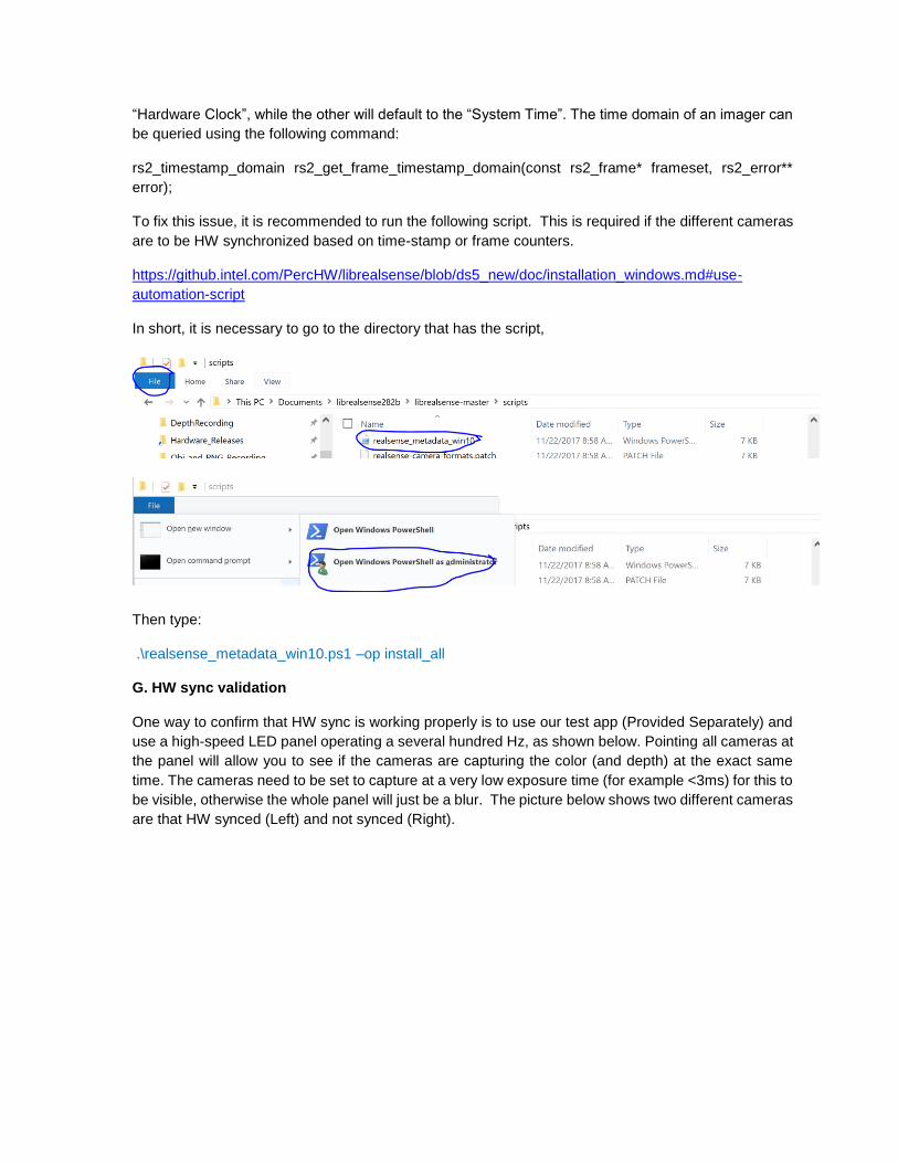
In short, it is necessary to go to the directory that has the script,
Then type:
.\realsense_metadata_win10.ps1 –op install_all
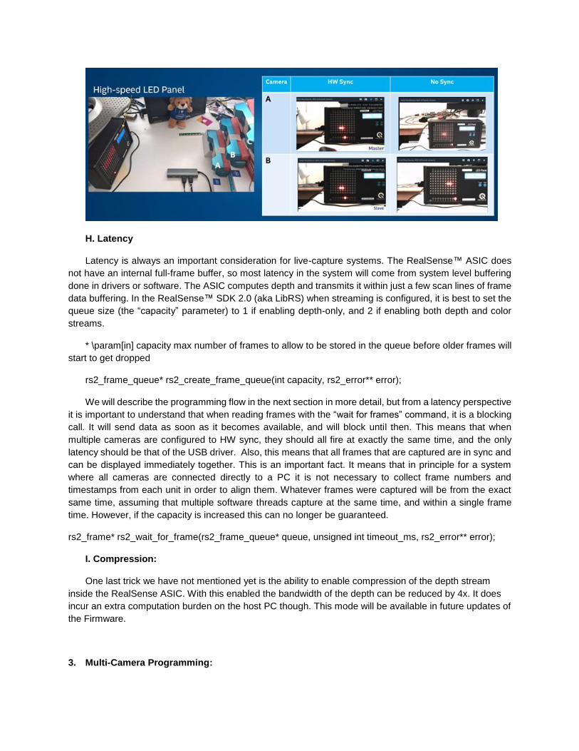
G. HW sync validation
One way to confirm that HW sync is working properly is to use our test app (Provided Separately) and
use a high-speed LED panel operating a several hundred Hz, as shown below. Pointing all cameras at
the panel will allow you to see if the cameras are capturing the color (and depth) at the exact same
time. The cameras need to be set to capture at a very low exposure time (for example <3ms) for this to
be visible, otherwise the whole panel will just be a blur. The picture below shows two different cameras
are that HW synced (Left) and not synced (Right).
H. Latency
Latency is always an important consideration for live-capture systems. The RealSense™ ASIC does
not have an internal full-frame buffer, so most latency in the system will come from system level buffering
done in drivers or software. The ASIC computes depth and transmits it within just a few scan lines of frame
data buffering. In the RealSense™ SDK 2.0 (aka LibRS) when streaming is configured, it is best to set the
queue size (the “capacity” parameter) to 1 if enabling depth-only, and 2 if enabling both depth and color
streams.
* \param[in] capacity max number of frames to allow to be stored in the queue before older frames will
start to get dropped
rs2_frame_queue* rs2_create_frame_queue(int capacity, rs2_error** error);
We will describe the programming flow in the next section in more detail, but from a latency perspective
it is important to understand that when reading frames with the “wait for frames” command, it is a blocking
call. It will send data as soon as it becomes available, and will block until then. This means that when
multiple cameras are configured to HW sync, they should all fire at exactly the same time, and the only
latency should be that of the USB driver. Also, this means that all frames that are captured are in sync and
can be displayed immediately together. This is an important fact. It means that in principle for a system
where all cameras are connected directly to a PC it is not necessary to collect frame numbers and
timestamps from each unit in order to align them. Whatever frames were captured will be from the exact
same time, assuming that multiple software threads capture at the same time, and within a single frame
time. However, if the capacity is increased this can no longer be guaranteed.
rs2_frame* rs2_wait_for_frame(rs2_frame_queue* queue, unsigned int timeout_ms, rs2_error** error);
I. Compression:
One last trick we have not mentioned yet is the ability to enable compression of the depth stream
inside the RealSense ASIC. With this enabled the bandwidth of the depth can be reduced by 4x. It does
incur an extra computation burden on the host PC though. This mode will be available in future updates of
the Firmware.
3. Multi-Camera Programming:
In this section we cover more details about the programming flow and logic. First we note that we mostly
tested our systems with scheme of using individual independent threads for each camera. We then created
an additional “supervisory” thread that would collect the frame data information when it was available, and
then composite it into a single 3D point-cloud to display. We also found it useful to start the cameras
staggered sequentially in time with a few seconds delay, according to lowest serial number, as opposed to
all at the same time. This approach was especially helpful in examining how many streams could be
supported simultaneously as it gives a clear indication of when bottlenecks are encountered, i.e. at which
channel number the streaming starts to have problems. It also allows for easy trouble shooting of which
camera may have an issue.
The RealSense™ SDK 2.0 is available as open-source code here:
https://github.com/IntelRealSense/librealsense
There are examples in many different programming languages of how to set up and stream from cameras,
so we will not go into a lot of detail here. We will focus instead of what happens after streams are captured.
As mentioned above, each frame from each camera will have a frame number and time stamp that can be
queried. Each camera will however have its own very precise time clock, and while they in principle should
be identical in nature, their times are derived from individual crystals and they will inevitably drift a few
milliseconds over the course of 10s of minutes. This also means that time stamps from different cameras
will have an offset. This offset can be subtracted in software, to “align” them all at a specific time.
Now to the somewhat counter intuitive aspect of time stamps. If NO HW sync is enabled, the time stamps
will now surprisingly appear to be perfectly aligned. This is because each individual ASIC is counting the
exact same number of cycles between frames, and then sending them off. So according to their own time-
lines they are sending frames at say, exactly 33.333ms intervals, for a 30fps mode. By contrast, if HW Sync
is enabled, the time stamps will actually drift over time.
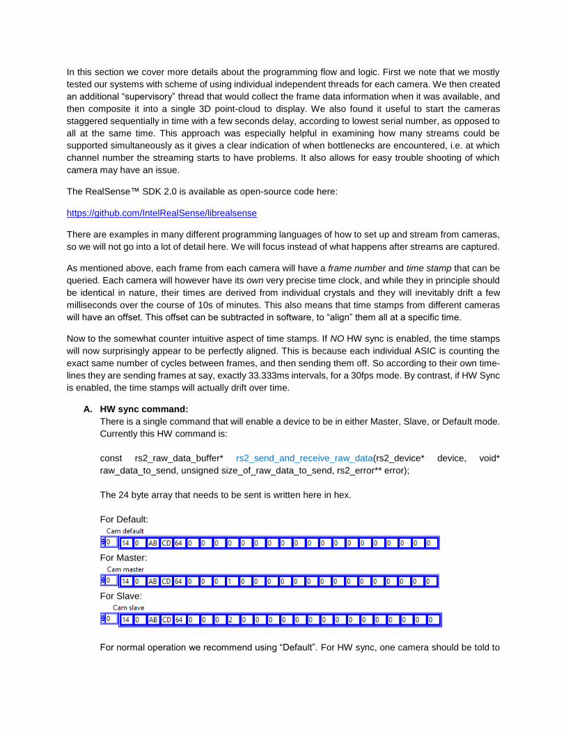
A. HW sync command:
There is a single command that will enable a device to be in either Master, Slave, or Default mode.
Currently this HW command is:
const rs2_raw_data_buffer* rs2_send_and_receive_raw_data(rs2_device* device, void*
raw_data_to_send, unsigned size_of_raw_data_to_send, rs2_error** error);
The 24 byte array that needs to be sent is written here in hex.
For Default:
For Master:
For Slave:
For normal operation we recommend using “Default”. For HW sync, one camera should be told to

be the Master, and all others should be set to slave. If an external sync is being provided, then all
should be set to slave.
B. Collecting synchronous frames:
As mentioned earlier, if no HW sync is applied, frames will be available asynchronously from each
camera. If the “capacity” is set to the minimal number (1 for depth-only, and 2 for depth+color), then
only the most recent frames will be available at any time, so frames from different cameras can
never misalign by more than 1 frame. If even better alignment is required, then the HW sync should
be applied. In this case all cameras will fire and capture frames at essentially identical times. Since
the calls are blocking from each camera, it should simply be a matter of collecting all frames and
displaying them.
However, if larger buffer size is used in the SDK or in the drivers and there is some concern about
making sure frames are aligned, it is also possible to align frames in software using either their
time-stamp or frame-number. Both approaches are valid but you do need to be careful during the
initial step of subtracting the offsets that the frames were not read across a frame boundary – for
example one camera could have a frame belonging to a previous frame time. The benefit of using
the frame counters is that they will not walk off over time3.
C. Aligning point-clouds:
Once depth maps and color images have been captured from each frame, the next step is to
calculate their 3D point-clouds and to align them. There are methods known in the art for doing
this. In our example, we found it sufficient to simply rotate the point-cloud data from each camera
using a 3D transform that would rotate and shift the point-clouds and form one large composite
point cloud.
So now it is time to look at the end result. In this example we set the resolution to 640x360 and
stream color and depth at 30fps. Below we show the depth and color views.
We also visualize the full point-cloud:
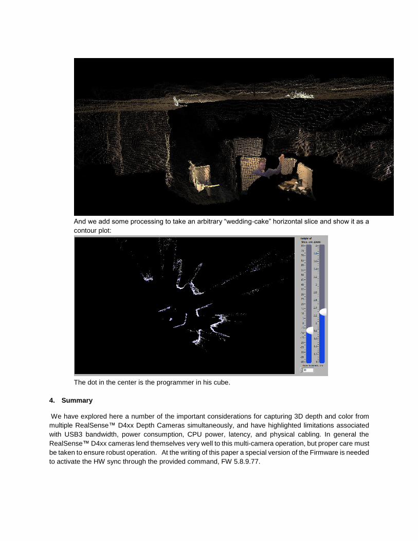
And we add some processing to take an arbitrary “wedding-cake” horizontal slice and show it as a
contour plot:
The dot in the center is the programmer in his cube.
4. Summary
We have explored here a number of the important considerations for capturing 3D depth and color from
multiple RealSense™ D4xx Depth Cameras simultaneously, and have highlighted limitations associated
with USB3 bandwidth, power consumption, CPU power, latency, and physical cabling. In general the
RealSense™ D4xx cameras lend themselves very well to this multi-camera operation, but proper care must
be taken to ensure robust operation. At the writing of this paper a special version of the Firmware is needed
to activate the HW sync through the provided command, FW 5.8.9.77.

1. https://en.wikipedia.org/wiki/USB_3.0
2. http://www.usb.org/developers/docs/whitepapers/bwpaper2.pdf
3. It should be noted that some ESD events may cause the frame counters to reset.


![arXiv:2002.07995v2 [cs.GR] 15 Apr 2020 · 2020. 4. 16. · depth data due to the popularity of 2.5D sensors, such as Microsoft Kinect, Intel RealSense, etc., multi-view RGB-D images](https://img.pdfslide.net/doc/110x75/5fd0a61b8d21411d4000b1c8/arxiv200207995v2-csgr-15-apr-2020-2020-4-16-depth-data-due-to-the-popularity.jpg)

![Skeleton-Based Human Action Recognition With Global ... Recognition... · human-machine interaction, etc [1]–[3]. With the development of depth sensors, such as RealSense and Kinect](https://img.pdfslide.net/doc/110x75/5ed98aa81b54311e7967c127/skeleton-based-human-action-recognition-with-global-recognition-human-machine.jpg)