Embed Size (px)
Citation preview

18 May 1962
Cog Service: USN FSN:
USA
TYPE CLASS:
USN
Used by
TIME STAN DARD AN/FSM-5 Functional Class: 8
USAF
MANUFACTURER'S NAME/CODE NUMBER: Lavoie Laboratories, ( 35225 ) .
fi•e Standard �1/FSN-5
FUNCTIONAL DESCRIPTION:
Time Standard AN/FSM-5 I s a fixed radio-station instrument consisting of a series of rack
mounted assemblies, is used to supply and maintain time information and standard frequency.
When set up and properly checked, this instrument is capable of supplying time information
correct to with in one mi 111 second .and frequency accurate to one part in 50 mi 11 ion if oper
ated in a room air-conditioned at 25 deg porm 2 deg c.
No field changes in effect at time of preparation.
TECHNICAL CHARACTERISTICS:
POWER REQUIREMENTS : 115 v, 60 eye, single ph.
Sl GNA L DATA : 1 kc, 10 kc, 100 kc, 1000 kc per sec.
KEYING PULSE : 0 .3 sec duration, 1 pps repetition rate.
INDIC ATION: .3 in. CR tube.
ij,8 AN/FSM-5: 1
, .
'"' . ,
,.
..
' )
.;;) •
....
·s,J
(
�
�
(
( "'
"·
(
AN/FSM-5 TIME STANDARD
RELATION TO OTHER EQUIPMENT: None.
EQUIPMENT REQUIRED BUT NOT SUPPLIED: None.
QTY ITEM
1 Time Standard AN/FSM-5 includes: 1 R. F. O scillator 0-76/U 1 F r equency Divider Assy
CV-87/FSM-5 1 Clock TD-31/FSM-5
1 Converter-FI 1 ter Assy
CV-88/FSM-5 1 Power Suppl y PP-�55/FSM-5 1 Power Supply PP-�56/FSM-5
1 Oscilloscope OS-13/U 1 Cab I net CY-597/G
1 Voltage Stabilizer 1 T est Prod MX-1015/U 1 R. F. Cable CG-55/U
REFERENCE DATA AND LITERATURE: None.
MAJOR COMPONENTS
STOCK NUMBERS
TUBE, CRYSTAL AND/OR SEMI-CONDUCTOR DATA:
Dl MENS IONS
(INCH ES)
10-1/� X 19 X 2Q-1/�
7 X 18-3/� X 19
12-1/2 X 19 X 21
10-1/2 X 18-1/2 X 19
10-1/2 X 19 X 19-1/�
7 X 16-1/� X 19
8-3/� X 19 X 20-1/�
22-3/8 X 26 X 87-1/2
8-7/8 X 13-27/32 X 1�-5/32
50 1 g
180 1 g
WE I GH T
( LBS)
9 5
29
65
�0
86-1/2
�1
�� 322
50
T UBES: (1) OA2 (1) OB2 (1) 3JP1 (8) 6AS6 (7) 6AS7 (1) 6AQ5 (3) 5686 (2) 6C�
(10) 12AU7 (2) 5R�G (6) 6SN7G (1) 6SL7G (2) 6X5GT (1�) 5963 (1) 6AL5 (1) 88 � (1) 5696 (3) 5R� (1) 6X� (2) 1 2AX7 (2) 565 1 (�) 6W� (1) 631P1 (�) 6AC7 (1) 6 V6GT (�) 5 727/2D21W
CRYSTALS: None u sed.
S EMI-CONDUCTORS: (1) 1N3�
PKGS
SHIPPING DATA
VOLUME ( CU FT)
PROCUREMENT DATA
PRO CURl NG SERVICE: USN
SPEC &/OR DWG:
�.8 AN/FSM-5: 2
DESIGN COG: USN, BuShi p s
WEIGHT (LBS)
CONTRACTOR LOCATION
Lovole Laboratories Morganville, N. J.
CONTRACT OR ORDER NO.
NObsr-�2300
TIME STANDARD AN/FSM-6
APPRO X.
UNIT COST
$5,000.00
�. 8 AN/FSM-5: 3
'�
"
"'
'}
'"') "
,.
':. �:;iJI
(
4,
,4
(
( ..
14
(
UNCI.t.SSIFIED
February 1960 Test-Time Base Measuring and Counting
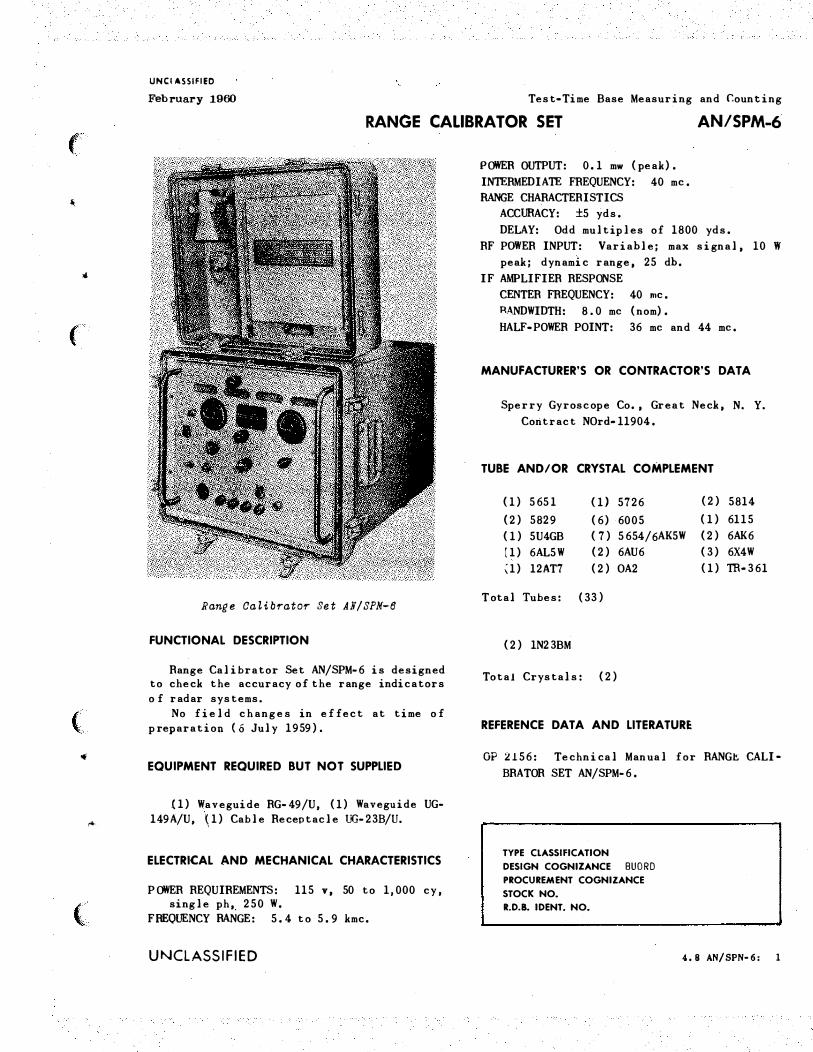
RANGE CALIBRATOR SET AN/SPM-6
Range CaLibrator Set AN/SPM-8
FUNCTIONAL DESCRIPTION
Range Calibrator Set AN/SPM-6 is designed to check the accuracy of the range indicators o f radar systems.
No field changes in effect at time of preparation (6 July 1959).
EQUIPMENT REQUIRED BUT NOT SUPPLIED
(1) Waveguide RG- 49/U, (1) Waveguide UG-149A/U, � 1) Cable Receptacle UG- 23B/U.
ELECTRICAL AND MECHANICAL CHARACTERISTICS
POWER REQUIREMENTS: 115 v, 50 to 1,000 cy, single ph,_ 25 0 W.
FREQUENCY RANGE: 5.4 to 5.9 kmc.
UNCLASSIFIED
POWER OUTPUT: 0.1 mw (peak).
INTERMEDIATE FREQUENCY: 40 me.
RANGE CHARACTERISTICS
ACCURACY: ±5 yds.
DELAY: Odd multiples of 1800 yds.
RF POWER INPUT: Varia ble; max signal, 10 W
peak; dynamic range, 25 db.
IF AMPLIFIER RESPONSE
CENTER FREQUENCY: 40 me.
RANDWIDTH: 8.0 me (nom).
HALF-POWER POINT: 36 me and 44 me.
MANUFACTURER'S OR CONTRACTOR'S DATA
Sperry Gyroscope Co., Great Neck, N. Y.
Contract NOrd-11904.
TUBE AND/OR CRYSTAL COMPLEMENT
(1) 565 1 (1) 5726 (2) 5814
(2) 5829 (6) 6005 (1) 6115
(1) 5U4GB (7) 5654/6AK5W (2) 6AK6
[1) 6AL 5 W (2) 6AU6 (3 ) 6X4W
�1) 12AT7 (2) OA2 (1) TR· 361
T otal Tubes: (3 3 )
(2) 1N23BM
Total Crystals: (2)
REFERENCE DATA AND LITERATURE
OP 2156: Technical Manual for RANG� CALI•
BRATOR SET AN/SPM-6.
TYPE CLASSIFICATION DESIGN COGNIZANCE BUORD PROCUREMENT COGNIZANCE STOCK NO. R.D.B. IDENT. NO.
4. 8 AN/SPN· 6: 1
UNCLASSIFIED
Test-Time Base Measuring and Counting February 1900
AN/SPM-6 RANGE CALIBRATOR SET
EQUIPMENT SUPPLIED DATA
QUANTITY OVERALL DIMENSIONS
I WEIGHT
PEl! NAME AND NOMENCLATURE EQUIPT
1 Range Calibrator Set AN/SPM-6 Including:
1 Range calibrator
1 Cord, Power CX-337/U
1 Case
1 Horn, Pickup
1 Cable Assy CG-92A/U
2 Crystal, Pair
2 Allen Wrench
4.8ANlSPiol-6: 2
(inches) (lbs.)
13-5/8 X 16 X 20 I 95.5
72 lg 0.75
2 X 3-1/8 X �-1/8 0.25
72 lg 1
UNCLASSIFIED
,,,
�
•
'')
) ..
...
,. ���
(
'-:
4
(
UNCLASSIFIED
April 1959 Test-Timebase 'Measuring and Counting
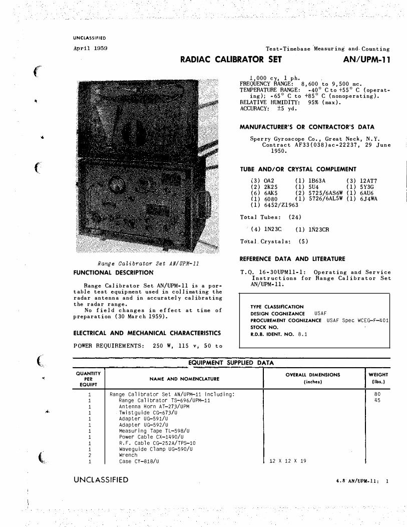
RADIAC CALIBRATOR SET AN/UPM-11
Range Calibrator Set AN/ UPM-11
FUNCTIONAL DESCRIPTION
Range Calibrator Set AN/UPM-11 is a por• t able test equipment used in collimating the radar antenn a and in accuratel y calibrating the radar range.
No field ch anges in effect at time of preparation (30 March 1959).
ELECTRICAL AND MECHANICAL CHARACTERISTICS
POWER REQUIREMENTS: 250 W , 115 v, 50 to
1,000 c y, 1 ph. FREQUENCY RANGE: 8,600 to 9,500 me. TEMPERATURE RANGE: -40° C to +55 ° C (operat·
ing); ·65° C to +85° C (nonoperating). RELATIVE HUMIDITY: 95% (max). ACCURACY: ±5 yd.
MANUFACTURER'S OR CONTRACTOR'S OAT A
Sperry G yroscope Co., Great Neck, N.Y. Contract AF33(038 )ac-22 237, 29 June
1950.
TUBE AND/OR CRYSTAL COMPLEMENT
(3) OA2 (1) 1B63A (3) 12AT7 (2) 2K25 (1) 5U4 (1) 5Y3G (6) 6AK5 (2) 5725/6AS6W (1} 6AU6 (1) 6080 (1) 5726/6ALSW (1) 6J4WA
(1) 6452;tZ1963
T6tal Tubes: (24)
·· (4) 1N23C (1) 1N23CR
Tdtal Crystals: (5)
REFERENCE DATA AND LITERATURE
T.Q. 16·30UPM11-1: Operating and Service Instructions for Range Calibrator Set AN/UPM-11.
TYPE CLASSIFICATION
DESIGN COGNIZANCE USAF PROCUREMENT COGNIZANCE USAF Spec WCEG-F-!1.01 STOCK NO.
R.D.B. I DENT. NO. 8 .1
( EQUIPMENT SUPPLIED DATA -----------------------�----------------------------�-------
..;
,..
(
QUANTITY
PER
EQUIPT
1 1 1 1 1 1 1 1 1 1 2 1
NAM£ AND NOMENCLATURE
Range Calibrator Set AN/UPM-11 Including: Range Calibrator TS-696/UPM-11 Antenna Horn AT-273/UPM Twistguide CG-.673/U Adapter UG-591/U Adapter UG-592/U Measuring Tape TL-598/U Power Cable CX-1!1.90/U R.F. Cable CG-252A/TPS-10 Waveguide Clamp UG-590/U Wrench case CY-818/U
UNCLASSIFIED
OVERALL DIMENSIONS
(inches)
12 X 12 X 19
WEIGHT
(lbs.)
80 !1.5
4 .II AN/UPM-11:
UNCLASSIFIED
April 1959 Test·Timebase Measuring and Counting
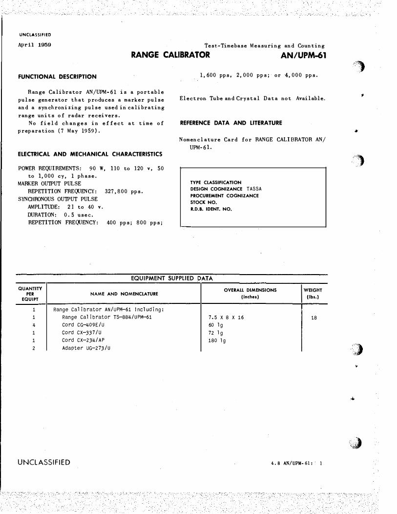
RANGE CALIBRATOR AN/UPM-61
FUNCTIONAL DESCRIPTION
Range Calibrator AN/UPM-61 is a portable
pulse generator that produces a marker pulse
and a synchronizing pulse used in calibrating
range units of radar recei vers.
No field changes in effect at time of
preparation (7 May 1959).
ELECTRICAL AND MECHANICAL CHARACTERISTICS
POWER REQUIREMENTS: 90 W, 110 to 120 v, 50
to 1, 000 cy, 1 phase.
MARKER OUTPUT PULSE
REPETITION FREQUENCY: 327, 800 pps.
SYNCHRONOUS OUTPUT PULSE
AM PLITUDE: 21 to 40 v.
DURATION: 0.5 usee.
REPETITION FREQUENCY: 400 pps; 800 pps;
1, 600 pps, 2, 000 pps; or 4, 000 pps.
Electron Tube and Crystal Data not Available.
REFERENCE OAT A AND LITERATURE
Nomenclature Card for RANGE C ALIBRAT OR AN/
UPM-61.
TYPE CLASSIFIC'-TION
DESIGN COGNIZANCE T ASSA PROCUREMENT COGNIZANCE
STOCK NO.
R.D.B. IOENT. NO.
EQUIPMENT SUPPLIED DATA
QUANTITY
PER EQUIPT
1
1
ll
1
1
2
NAME AND NOMENCLATURE
Range Calibrator AN/UPM-61 Including:
Range Calibrator TS -88�/UPM-61
Cord CG-409E/U
cord CX-.3.37 /u
Cord CX-2.34/ AP
Adapter UG-27.3/U
UNCLASSIFIED
OVERALL DIMENSIONS
(inches}
7.5X8X16
60 lg
72 1 g
180 lg
I WEIGHT
(lbs.)
18
4.8 AN/UPM-61:
'�
.,
•
')
) "
,...
J. ·�'" ��
(
-
•
(
( ..
4
(
UNCLASSIFIED
Jnne 1957 Test•Time Base Measuring and Counting
OSCILLOSCOPE AN/USM-248
FUNCTIONAL DESCRIPTION
The AN/USM-248 is a portable test set for bench•testing all types of �lectronic equip• ment. It displays time variation of a voltage pulse or wave with self-contained means for measuring its duration, displacements, and instantaneous magnitude. Auxil iary features include a calibrating generator for accurate measurement of instantaneous values of signal without recourse to external standards, a choice of five time markers for accurate time measurements, and a trigger generator with five fixed ranges for triggering both the oscilloscope and external apparatus.
No field changes in effect at t ime o f preparation (25 October 1956).
RELATION TO OTHB EQUIPMENT
Similar to and interchangeable with AN/ USM-24 and AN/USM-24 A for different component parts.
a.ECTRICAL AND MECHANICAL CHARACTalmCS
PRESENTATION: 3 in. CR tube. SWEEP DATA
FREQU ENCY RANGE: 8 to 600000 cps re·
current. TIME DURATION: 1.25 to 12500U us�c trig·
gered. .
DEFLECTION SENSITIVITY DATA VERTICAL: 0.035 v rms per in. HQRIZONTAL: 4.0 v rms per in.
FREQUENCY RESPONSE DATA
VERTICAL: 4 cps to 10 me. HORIZONTAL: 0.5 cps to 700 kc. BEAM MODULATION: 50 cps to 10 me.
INPUT IMPEDANCE HORIZONTAL: 300000 ohms. VERTICAL: 300000 ohms. BEAM MODULATION: 56000 ohms.
POWER REQUIREMENTS: 105, 115 or 125 v, 50 to 1000 cps, single phase, 215 W.
MANUFACTURR'S 01 CONTIACTOI'S DATA
Waterman 'Products Company, Ine., Phil a• delphia, Pennsylvania. Contract NObsr 52205, dated 15 January
1951. Approximate Cost: $625.00 with equip·
Rlen t spares.
TUBE AND/OR CRYSTAL COMPLEMENT
No Electron Tubes.
REFERENCE DATA AND UTEIATUIE
Nomenclature Card for Oscilloscope AN/USM• 24& .
TYPE CLASSIFICATION
DESIGN COGNIZANCE BUSH 1 PS PROCUREMENT COGNIZANCE MIL-C>-15�58A(SHIPS) STOCK NO.
R.D.B. IDENT. NO.
EQUIPMENT SUPPLIED DATA
QUANTITY PER
EQUIPT
1
NAME AND NOMENCLATURE
Oscilloscope AN/USM-2�8 including:
(1) RF Cable Assembly with (2) Test Prod
(2) RF Accessory Cable Assembly
(3) Connector, Adapter UG-25 5/U
(3) Connector, Adapter UG-273/U (1) connector, Adapter UG-27�/U
(�) Connector, Adapter, Binding Post
(1) Power Cable (1) wrench, Spanner (1) wrench, Hex, No. 6 socket Head
(1) wrench, Hex, No. 8 Socket Head (2) Technical Manual (1) Set of Spare Parts
UNCLASSIFIED
OVERAU DIMENSIONS
(inchu)
�Jl..-9/ 16 X 1ij-11/ 16 X 17-1/B
WEIGHT
(llta.)
4. 8 AN/USM-248:
�
a June 1962 · 6625-611-3-211-29 OSCILLOSCOPE AN/USM-211-C �og Service: FSN: 6625-611-3-3327 W/S Functional Class:
USA USN USAF
TYPE CLASS:
MANUFACTURER'S NAME/CODE NUMBER: waterman Products co., Inc.
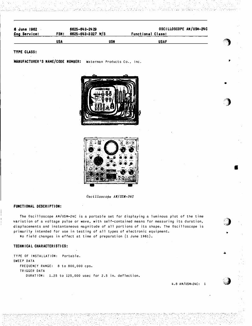
Oscilloscope AN/OSN-2�0
FUNCTIONAL DESCRIP TION:
The Oscilloscope AN/USM-2�C is a portable set for displaying a luminous plot of the time
variation of a voltage pulse or wave, with self-contained means for measuring its duration,
displacements and instantaneous magnitude of all portions of its shape. The Oscilloscope is
primarily intended for use in testing of all types of electronic equipment.
No field changes in effect at time of preparation ( 1 June 1961) .
TECHNICAL CHAR ACTERISTICS:
TYPE OF INSTALLATION: Portable.
SWEEP DATA
FREQUENCY RANGE: 8 to 800,000 cps.
TRIGGER DATA
DURATION: 1.25 to 125,000 usee for 2.5 in. deflection.
�.8 AN/USM-2�C: 1
""·· ;,
.,
•
/")
,,,) •
,.
. . ·· .. � . ..
•
(
•
..
(
I
( ..
•
(
AN/USM-2�C OSCILLOSCOPE
INTERNAL TRIGGER
DU RATION: Approx 1.5 usee. RISE TIME: 0.5 usee. REPETITION RATE: 50, 300, 800, 2,000, 5,000 pps accura te to porm 5%. AMPLITUDE: 25 to 50 v •
SCREEN MARKER INTERVALS: 0.2, 1, 10, 100, 500 usee.
DEFLECTION SENSITIVITY DATA THRU AMPLIFIER (NOMINAL)
VERTICAL: 0.05 v rms per inch. HORIZONTAL: 3.5 v rms per inch •
DIRECT TO PLATES VERTICAL: 110 v rms per inch. HORIZONTAL: 150 v rms per inch.
F REQUENCY RESPONSE (NOMINAL)
X-AX IS: 8 cps to 800 kc. Y-AX IS: 2 cps to 8 me. Z-AX IS: 6 cps to 5 me._
INPUT IMPEDANCE (NOMINAL) X-AXIS: 5.6 meg. Y-AXIS; 0.3 meg. Z-AX IS: 0. 65 6 meg.
OPERATING POWER RQMT: 110 to 130 v, 50 to �00 cps, sing le ph.
RELATION TO OTHER EQUIPMENT: Non e.
EQUIPMENT REQUIRED BUT NOT SUPPLIED: N on e.
MAJOR COMPONENTS
QTY
1
1 1
1* 2* 2* 1* 2*
�· 1* 2* 1* 1* 1* 1*
ITEM
Oscilloscope AN/USM-2� c consists of: Oscilloscope OS-51/USM-2�C Cover, Combination case
CW-3 62 /USM-2�C Power, Cable CX-3092/USM-2�C T est, Lead CG-�09/U (8 ft o in.) T est, Lead CG-883A/USM-2�
Test, Lead CG-1277/USM-24C Adapter UG-255/U Adapter UG-924/U Adapter UG-27�/u Adapter UG-273 /U Adapter UG-201A/U Adapter UG-3�9A/U Wrench, Allen no. 4 Wrench, Allen no. 6
�.8 AN/USM-2�C: 2
STOCK NUMBERS DIMENSIONS (INCHES)
WEIGHT ( LBS)
1�-13/16 X 1�-7/8 X 17-16/32 58
12-19/6� X 1�-3/16 X 17-5/32 50,5 2-25/32 X 1�-3/16 X 17-11/32 �.25
1-5/32 od x 72 lg 27/M od x 96 lg 13/16 od X 58 lg 1-1 /� od X �2-3 N
5/8 od X 1-3/8 9/16 od X 1-13/16 9/16 X 1-1/16 X 1-9/32-11/16 od x 1-5/16 13/16 od x 1-5/16
�/8 od X 1-9/16
3/6� X 5/� X 1-13/16 1/16 X 5/8 X 1-13/16
3/8 9/16
5/8 1/2
li./13 3/16 -1/16 1/8 1/16 1/16
\ --- - --- - ···---
OSCILLOSCOPE AN/USM-21JC ·
QT� ITEM STOCK NUMBERS DIMENSIONS WEIGHT (INCHES) ( LBS)
'') 1* 1* 2**
Wrench, Allen no 8 Wrench, Spanner TWA003 Technical Manual NAVSHIPs-92�65
NOTE: *Mounted in cover cw-.362/USM-2�C.
5/6� X 11/16 X 1-15/16 7/16 od X �-1/8 lg 1/2 X 8-3/� X 11-1/2
1/16 3-1/2
••one book is contained in cover CW-362/USM-2�C, the other is packed in the shipping container.
REFERENCE DATA AND LITERATURE:
NAVSHIPS 92�65: Techni c a l Manual TM-11-5103A for Oscilloscope AN/USM-2�C.
TUBE, CRYSTAL AND/OR SEMI-CONDUCTOR DATA:
TUBES: (1) OA2WA (1) 5719
(2) 1V2 (1) 3JP1 (3) 6AH6 (2) 6AN5WA (5) 12AT7WA (7) 12AU7A {2) 5726/6AL5W (2) 6135 (�) 6203
CRYSTALS: None used.
SEMI-CONDUCTORS: None used.
PKGS
1 1
PROCURING SERVICE:
SHIPPING DATA
VOLUME {CU FT)
6.15 0.59
PR9CUREMENT DATA
DESIGN COG: TASSA SPEC &/OR DWG: MIL-0-15�58A(SHIPS)
WEIGHT (LBS)
117 10
�.8 AN/USM-2�C: 3
..
;;..
'')
.#
.•. .)
f
�
..
(
( ..
•
{
21 February 1963
Cog Service: USN FSN: F6625-776-0�28
ELECTRONIC COUNTER CAQI-52�0 Functional Class: 8.6
TYPE CLASS:
USA USN
used by
MANUFACTURER'S MAME/CODE NUMBER: Hewlett- Packard Company, ( 28480) .
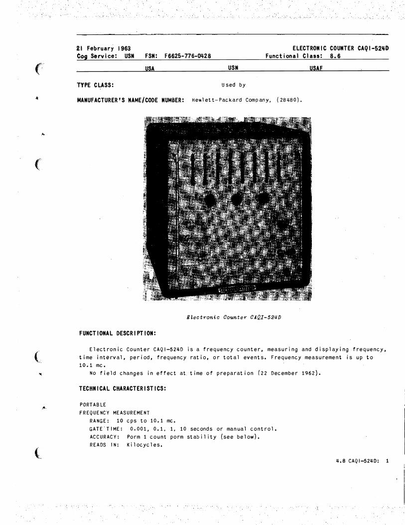
ELectronic Counter CAQI-52�D
FUNCTIONAL DESCRIPTION:
USAF
Electronic Counter CAQI-524D is a frequency counter, measuring and displaying frequency,
time interval, period, frequency ratio, or total events. Frequency measurement is up to
10.1 me.
No field changes in effect at. time of preparation (22 December 1962) •
TECHNICAL CHARACTERISTICS:
PORTABLE
FREQUENCY MEASUREMENT
RANGE: 10 cps to 10.1 me.
GATE TIME: 0.001, 0.1, 1, 10 seconds or manual control.
AC CURACY: Porm 1 count porm stability (see below ) .
READS IN: Kilocycles.
4.8 CAQI-5240: 1
CAQI-52qD ELECTRONIC COUNTER
PERIOD MEASUREMENT
RANGE: 0 cps to 10 kc.
GATE TIME: 1 or 10 cycles of unknown.
ACCURACY: Porm 0.3% (measurement one period). Porm 0.03% (ten-period average).
STANDARD FREQUENCY COUNHD: 10 cps; 1 or 100 kc; 10 me, or externally applied frequency.
READS IN: Seconds,.milliseconds or microseconds.
GENERAL
REGISTRATION: 8 numbered columns; 99,999,999 maximum count.
STABILITY: 3 /100,000,000 short term; 5/108 per week.
DISPLAY TIME: Variable 0.1 to 10 seconds in steps of gate time selected. Display can be
held indefinitely.
INPUT VOLTAGE: 1 v rms minimum 1.5 v peak, Rise time 0.2 sec max.
INPUT IMPEDANCE: Approx 1 megohm, �0 uuf shunt.
POWER: 115/230 v porm 10%, 50 to 60 cps, 600 w.
RELATION TO OTHER EQUIPMENT:
This equipment is identical electrically with CAQI-52�C, but has an a-decade numerical
readout using neon indicators instead of line "number tube" readout.
EQUIPMENT REQUIRED BUT NOT SUPPLIED:
(1) Video Cable Assy CAQI-AC-16K; (1) Plug-In Unit CAQI-525A; (1) Plug-In Unit CAQI-525B;
(1) Plug-In Unit C AQI-526A; (1) Plug-In Unit CAQI-526B; (1) Plug-In Unit CAQI-526C.
MAJOR COMPONENTS
QTY
1
1
2
ITEM
Electronic Counter CAQI-52�D
Cable Assy CAQI-AC-16D
Technical Manual
REFERENCE DATA AND LITERATURE:
STOCK NUMBERS DIMENSIONS
(INCHES)
20 X 21.125 X 23.5
0,5 X 0,5 X ��
0,5 X 8.5 X 11
NAVSHIPS 93771: Technical M anual for Electronic Counter Model 52�D.
TUBE, CRYSTAL AND/OR SEMI-CONDUCTOR DATA:
TUBES: ( 1) OB2
(1) 58��
(6) 6CB6
(2) 2021
(13) 596 3
(3) 12AT7
CRYSTALS: None used.
(1) 5Y 3GT
(7) 6AH6
SEMI-CONDUCTORS: (5�) H D 2135(Hughes)
�.8 CAQI-52�D: 2
(3) 5R�GY
(2) 6AQ5
( 2) G 12(CAQI)
(2) 565�
(3) 6AL5
(1) 5687 (8) 5725
(2) 6AS7GA _ (7) 6AU6
WEIGHT
( LBS)
118
1
1
],
y
�
·')
) ..
,.
*)
(
-
(
( '
(
4
PKGS
1
PROCURING SERVICE: USN
SPEC &/OR DWG:
CONTRACTOR
Hewlett-Packard Company
Model no. 52110
ELECTRONIC COUNTER CAQI-52ijD
SHIPPING DATA
VOLUM� (CU FT) WEIGHT (LBS)
12. 7 157
PROCUREMENT DATA
DESIGN COG: Commercial
LOCATION.
Palo Alto, California
CONTRACT OR
ORDER NO.
NObsr-81557,
27 June 1960
APPROX.
UNIT COST
$2,150.00
11.8 CAQI-52110: 3
UNCLASSIFIED
APril 1958 Test-Time JJ:-:>e Measuring and Counting
RANGE CALIBRATOR TS-1 02/ API TS-1 02A/ AP
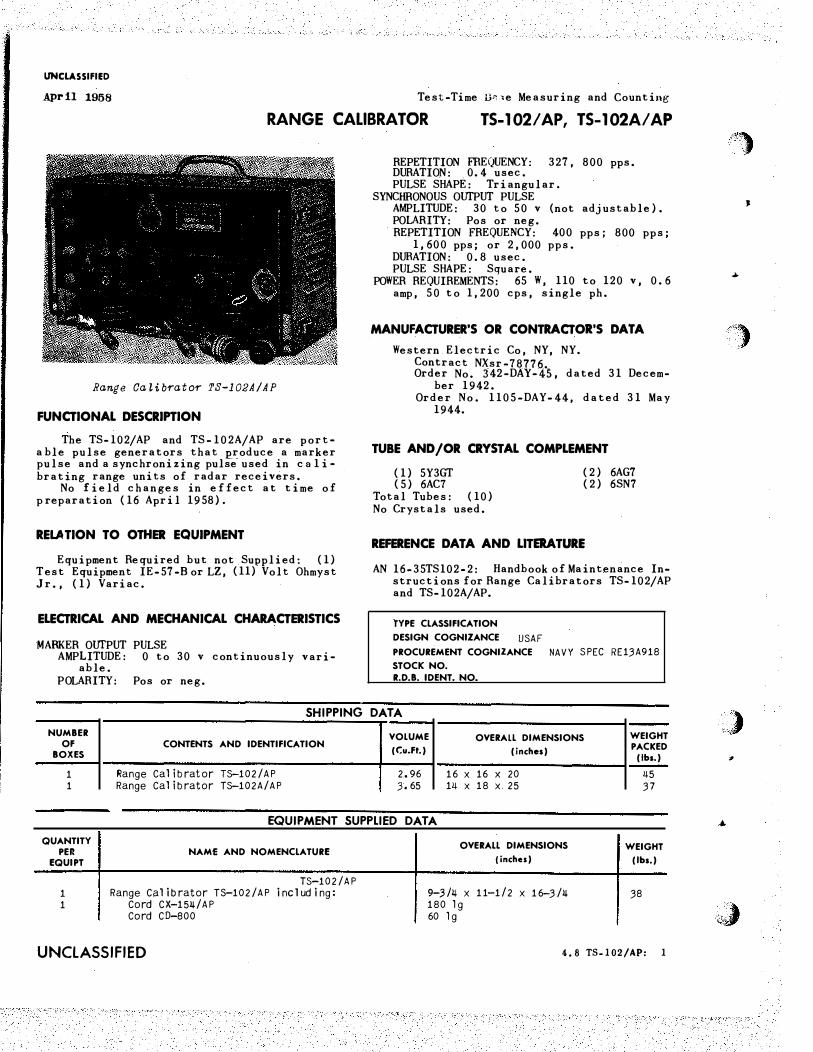
Range CaLib�ato� TS-102A/AP
FUNCTIONAL DESCRIPTION
The TS-102/AP and TS-102A/AP are porta ble pulse generators that �roduce a marker pulse and a synchronizing pulse used in c a 1 i brating range units of radar receivers.
No field changes in effect at time of p reparation (16 April 1958).
RELATION TO OTHER EQUIPMENT
Equipment Required but not Supplied: (1) T est Equipment IE-57-Bor LZ, (11) Volt Ohmyst Jr., (1) Variac.
ELECTRICAL AND MECHANICAL CHARACTERISTICS
MARKER OUTPUT PULSE AMPLITUDE: 0 to 30 v continuously vari
able. P OLARITY: Pos or neg.
REPETITION FREQUENCY: 327, 800 pps. DURATION: 0.4 usee. PULSE SHAPE: Triangular.
SYNCHRONOUS OUTPUT PULSE AMPLITUDE: 30 to 50 v (not adjustable). POLARITY: Pos or neg. REPETITION FREQUENCY: 400 pps; 800 pps;
1,600 pps; or 2,000 pps. DURATION: 0.8 usee. PULSE SHAPE: Square.
POWER REQUIREMENTS: 65 W, 110 to 120 v, 0.6 amp, 50 to 1,200 cps, single ph.
MANUFACTURER'S OR CONTRACTOR'S DATA
Western Electric Co, NY, NY. Contract NXsr-78776. Order No. 342-DAY-45, dated 31 Decem-
ber 1942. Order No. 1105-DAY-44, dated 31 May
1944.
TUBE AND /OR CRYSTAL COMPLEMENT
(1) 5Y3GT ( 5) 6AC7
Total Tubes: (10) No Crystals used.
(2) 6AG7 ( 2) 6SN7
REFERENCE DATA AND LITERATURE
AN 16-35TS102-2: Handbook of Maintenance Instructions for Range Calibrators TS-102/AP and TS-102A/AP.
TYPE CLASSIFICATION
DESIGN COGNIZANCE USAF PROCUREMENT COGNIZANCE NAVY SPEC RE13A918 STOCK NO.
R.D.B. IDENT. NO.
SHIPPING DATA
NUMBER VOLUME OVERALL DIMENSIONS WEIGHT OF CONTENTS AND IDENTIFICATION
(C:u.Ft.) (inches) PACKED BOXES (lbs.)
1 Range Calibrator TS-102/AP 2 .• 96 16 X 16 X 20 45 1 Range Calibrator TS-102A/AP 3· 65 14 X 18 X 25 37
EQUIPMENT SUPPLIED DATA
QUANTITY PER
EQUIPT
1 1
NAM£ AND NOMENCLATURE
TS-102/AP Range Calibrator T�102/AP including:
Cord CX-154/AP Cord CD-800
UNCLASSIFIED
OVERALL DIMENSIONS
(inches)
9-3/4 X 11-1/2 X 16-3/4 180 lg 60 lg
WEIGHT
(lbs.)
38
4.8 TS-102/AP: 1
"")
J
....
. .. ;, ,,
,,,/
,) .,
..,
·�;J
(
"
,.
(
( '
•
(
Test-Time Base Measuring and Counting
TS-102/AP, TS-102A/AP RANGE CALIBRATOR
QUANTITY
\ PER
EQUIPT
1 1 �
EQUIPMENT SUPPLIED OAT A
NAME AND NOMENCLATURE
T5-102A/AP Range Calibrator T5-102A/AP including:
Cord CX-2.3�/ AP Cord CG-107/U
OVERALL DIMENSIONS
(inches)
9-7/8 X 11-17-7/8 180 lg 60 lg
UNCLASSIFIED
April 1958
WEIGHT
(lbs.)
31
-,
4.8 TS-102/AP: 2 UNCLASSIFIED 1
UNCLASSIFIED Test-Timebase Measuring and Counting
December 1956 RANGE CALIBRATOR TS-126/AP
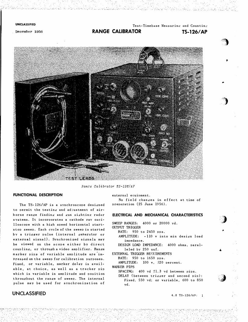
RanQe CaLibrator TS-126/AP
FUNCTIONAL DESCRIPTION
The TS-126/AP is a synchroscope designed
to permit the testing and adjustment of air
horne range finding and gun sighting radar
systems. It incorporates a cathode ray osci
lloscope with a high speed horizontal start
stop sweep. Each cycle of the sweep is started
b y a trig�<er pulse (internal generator or
external signal). Synchronized signals may
be viewed on the scope e ither by direct
coupling� or throup:h a video amplifier. Ran_ge
m arker pips -of variable amplitude are 'im
Pressed on the sweep for calibration purposes.
Fixed, or variable� marker delay is avail
able. at choice. as well as a tracker pip
which is variable in amplitude and position
throughout the range of sweep. The internal pulse may be used for synchronizat ion of
UNCLASSI_FIED
external eauioment.
No field changes in effect at time of preparation (25 June 1956).
ELECTRICAL AND MECHANICAL CHARACTERISTICS
SWEEP RANGES: 4000 or 20000 yd. OUTPUT TRIGGER
RATE: 950 to 2450 pps.
AMPLITUDE: -110 v into min design load impedance.
DESIGN LOAD IMPEDANCE: 4000 ohms, paralleled by 250 uuf.
EXTERNAL TRIGGER REQUIREMENTS RATE: 950 to 1650 pps. AMPLITUDE: 100 v, ±2 0 percent.
MARKER PIPS SPACING: 400 vd ±1.3 vd between pips. DELAY (between trigger and second pip):
Fixed, 550 vd; or variable, 600 to 850 yd.
4.8 TS-126/AP:
�l
'
•
)
) . .
. •
�
,;�
(
�
(
( "'
"
(
Test-Timebase Me asuring and Counting UNCLASSIFIED
TS-1 26/AP RANGE CALIBRATOR December 1956
TRACER PIPS: V ariable from 600 to 4500 vd
bevond trigger.
VERTICAL DEFLECTION SENSITIVITY
DIRECT COUPLING: 260 to 7000 v per ln.
VERTICAL AMPLIFIER: 7 v to llOO v per in.
P OWER REQUIREMENTS: 115 v. 400 to 600 cps,
80 W.
MANUFACTURER'S OR CONTRACTOR'S DATA
Galvin Mf�. Corp . • Chicago. Ill.
Contract: 774-DAY-44,
Contract: 774-DAY-46,
TUBE AND/OR CRYSTAL COMPLEMENT ( 1) 5Y3GT/G ( 1) 6SL7GT ( 1) 2x2 (5) 6SN7GT (2) 6AC7 (1) 2 AP1
T otal Tubes: ( 11)
REFERENCE DATA AND LITERATURE
AN16-35TS126-2M: Technical Manual f or Range Calibrator TS-126/AP.
TYPE CLASSIFICATION
DESIGN COGNIZANCE USAF PROCUREMENT CoOGNIZANCE
STOCK NO.
R.D.B. IDENT. NO.
EQUIPMENT SUPPLIED DATA
QUANTITY
I OVERALL DIMENSIONS WEIGHT
PER NAME AND NOMENCLATURE (inches) (lbs.)
EQUIPT
1 Ranqe Calibrator TS-126/AP 10-3/16 X 10-1/2 X 1�-3/16 '31-1 /2 1 Low-Voltaqe Test Lead (Red) 3 8-1/2 1/16 1 Low-Voltaqe Test Lead /(Black) 3 8-1 /2 1/16 1 Hiah-Voltaqe Test Lead 3 8-1 /2 1 /16 1 Cord CG-2�3 /AP 108 �-1 /2 1 Cor d CG-2�3/AP 36 2
4.8 TS-126/AP: 2 UNCLASSIFIED
18 February 1963 Cog Service: USN
F6625-369-5998 FSN: F6625-500-0709 W/S
RANGE CALIBRATOR TS-573/UP Functional Class: 8.1
TYPE CLASS:
USA USN
Std Std
USAF
MANUFACTURER'S NAME/CODE NUMBE R: Radio Corp of America, RCA Victor Div., (79089).
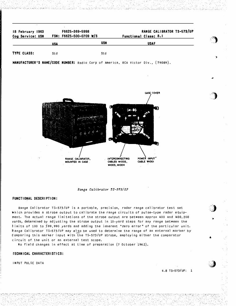
FUNCTIONAL DESCRIPTION:
CABLES WI002, Wl003, Wl004
Range Calib�ato� TS-573/UP
INPUT* CABLE WIOOI
Range Calibrator TS-573/UP is a portable, precision, radar range calibrator tes t set tNhich provides a strobe output to calibrate the range circuits of pulse-type radar equipmen t. The actual range 1 i mi tat ions of the strobe output are between approx 400 and 400,200 yards, determined by adjusting the strobe output in 10-yard steps fo r any range between the n imits of 1 00 to 399,990 yards and adding the inherent "zero error" of the particular unit. �ange Calibrator TS-573/UP may also be used to determine the range of an external marker by comparing this marke r input with the TS-573/UP strobe, employing either the comparator circuit of the unit or an external test scope.
No field changes in eff ect at time of preparation (7 October 1 962).
rECHNICAL CHARACTERISTICS:
INPUT PULSE DATA
4.8 T5-573/UP: 1
,,!;' ,,o
')
#
')
,,) •
•
• '�:�
(
•
"'
(
( ..
•
(
TS-573/UP RANGE CALIBRATOR
EXTERNALLY TRIGGERED: �7 to 5000 pps, pos or neg, 10 to 50 v. INTERNALLY TRIGGERED: 160r �80, 800, 1200 or 2�00 pps.
OUTPUT TRIGGER DATA: 75 ohms (low imp ) (10 v min); 5000 ohms (high imp); pos or neg. OUTPUT MARKER DATA: Range type; 160, �80, BOO, 1200, and 2�00 pps recurrence frequency
range; accuracy porm (0.01� P10 yds}; base width 0.3 usee; amplitude v�riable from 0 at 75 ohms impedance; pos or neg.
POWER REQUIREMENTS: 115 v, 50 to 1000 eye, single ph. OUTPUT: Adjustable In 10-yd increments from �00 yds to �00000 yds. OPERATING TEMPERATURE: M�O deg C to P55 deg C.
RELATION TO OTHER EQUIPMENT: None.
EQUIPMENT REQUIRED BUT MOT SUPPLIED: None.
QTY ITEM
1 Range Calibrator T3-573/UP 1 Set of Equipment Spare Parts
REFERENCE DATA AND LITERATURE:
MAJOR COMPONENTS
STOCK NUMBERS DIMENSIONS ( INCHES)
12 X 13 X 22-1/2
WEIGHT (Las)
��-1/�
N AVSHIPS 91760: Technical Manual for Range Calibrators TS-573/UP, TS-573A/UP, TS-5738/UP and TS-573C/UP.
TUBE, CRYSTAL AND/OR SEMI-CONDUCTOR DATA:
TUBES: ( 2�) 6BF7 /6BF7W ( �) 578� ( 6) 58�0 ( 1) 5902
CRYSTALS: (1) CR-18/U
SEMI-CONDUCTORS: (�6) G5S3
PKGS
1
1
PROCURIN G SERVICE: USN
SHIPPING DATA
VOLUME {CU FT)
8.3 0.25
PROCURE�EMT DATA
DESIGN COG: USN, BuShips
SPEC &/0 R DWG: M I L-C-15539 (SHIPS)
� .8 T3-573/UP-> 2
WE I GHT ( LSS)
130 20
CONTRACTOR
Raaio Corp of America,
RCA VIctor Div.
LOCATION
Camden, N . J .
RANGE CALIBRATOR TS-573/UP
CONTRACT OR
ORDER NO.
NObsr-52.327,
17 September 1952
APPROX.
UNIT COST
�.8 TS-573/UP: 3
'''··. "·,
..
#
'')
.)' ;, Jr
•
'':J
(
-
...
(
( 'II
...
(
19 February 1963 Cog Service: USN
TYPE CLASS:
FSN: F68ij0-6ij3-1295 W/S
USA USN
Used by
RANGE CALIBRATOR TS-573A/UP Functional C1ass: 8.1
USAF
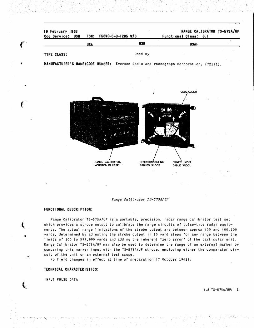
MANUFACTURER'S NAME/CODE NUMBER: Emerson Radio and Phonograph Corporation, (72171).
FUNCTIONAL DESCRIPTION:
INTERCON
CABLES WI002
Range Ca�ibrator f3-578A/UP
CABLE WIOOI
Range Calibrator TS-57,3A/UP is a portable, precision, radar range calibrator test set
which provides a strobe output to calibrate the range circuits of pulse-type radar equip
ments. The actual range limitations of the strobe output are between approx �oo and �00,200 yards, determined by adjusting the strobe output in 10 yard steps for any range between the
1 imits of 100 to ,399,990 yards and adding the inherent •zero error" of the particular unit.
Range Calibrator TS-57.3A/UP may also be used to determine the range of an external marker by
comparing this marker input with the TS-57.3A/UP strobe, employing either the comparator. cir
cuit of the unit or an external test scope •
No field changes in effect at time of preparation (7 October 1962);
TECHNICAL CHARACTERISTICS:
INPUT PULSE DATA
�.8 TS-57,3A/UP: 1
TS-673A/UP RAIGE CALIBRATOR
EXTERNALLY TRIGGERED: ij7 to 5,000 pps, pos or neg, 10 to 50 v. INTERNALLY TRIGGERED: 160, ij80, 800, 1,200 or 2,ij00 pps.
OUTPUT TRIGGER DATA: 75 ohms (low imp) (10 v min); 5,000 ohms (high imp); pos or neg. OUTPUT MARKER DATA: Range type; 160, �80, 800, 1,200, and 2,ijOO pps recurrence frequency
range; accuracy porm (0.011 P10 yds); base width 0.3 usee; amplitude variable from o at 75 ohms impedance; pos or neg.
POWER �EQUIREMENTS: 115 v, 50 to ij50 eye, single ph. OUTPUT: Adjustable i� 10-yd increments from ijOO yds to �00,000 yds. OPERATING TEMPERATURE: Mij� deg C to P55 deg C.
RELATION TO OTHER EQUIPMENT: None.
EQUIPMENT REQUIRED BUT NOT SUPPLIED: None.
QTY
1 1
ITEM
Range Calibrator TS-573A/UP Set of Equipment Spare Parts
REFERENCE DATA AND LITERATURE:
MAJOR COMPONENTS
STOCK NUMBERS DIMENSIONS (INCHES)
12 X 13 X 22-1/2
WEIGHT (LBS)
J+ij-1/J+
NAVSHIPS 91760: Technical Manual for Range Calibrators TS-573/UP, TS-573A/UP, TS-5736/UP, TS-573C/UP.
TUBE, CRYSTAL AND/OR SEMI-CONDUCTOR DATA:
TUBES: (2ij) 6021A (ij) 578.
CRYSTALS: (1) CR-18/U
SEMI-CONDUCTORS: (52) 1N198
PKGS
1 1
(6) 58110 (1) 5902
SHIPPIIG DATA
VOLUME (CU FT)
8.3 0.25
PROCUREMENT DATA
PROCURING SERVICE: USN SPEC &/OR OWG: MIL-C-15539A(SHIPS)
11.8 TS-573A/UP: 2
DESIGN COG: USN, BuShips
WEIGHT (LBS)
130 20
"'')
-.
i
'")
,,,,) lJ
•
'"i)
(
•
..
(
( ..
4
(
CONTRACTOR
Emerson Radio aRd Phono
graph Corporation
LOCATION
Jersey City, New ��rsey
RANGE CALIBRATOR TS-573A/UP
CONTRACT OR
ORDER MO.
NObsr-6�799,
20 June 1955
APPROX.
UNIT COST
�.8 TS-573A/UP: 3
2 July 1962 Cog Service:
TYP E CLASS:
6626-606-1616 FSN: 6626-639-7337 W/S
USA USN
MANUFACTURER'S NA ME/CODE NUMBER: Radio Corp of America.
RANGE CALIBRATOR TS-673 B/UP Functional Class:
USAF
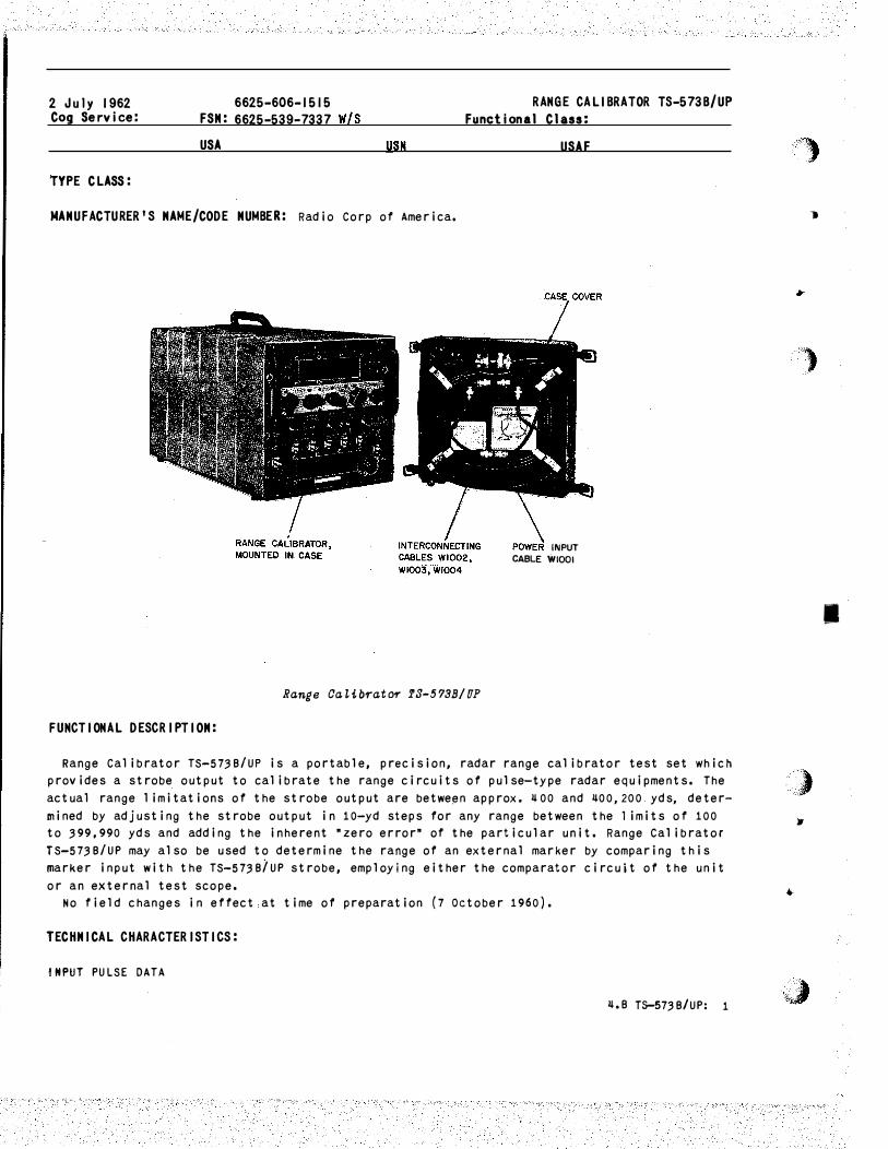
INPUT CABLE WIOOI
Range OaZibf'"ator !S-573B/UP
FUNCTIONAL DESCRIPTION:
Range Calibrator TS-5738/UP is a portable, precision, radar range calibrator test set which provides a strobe output to calibrate the range circuits of pulse-type radar equipments. The actual range 1 imitations of the strobe output are between approx. 4 00 and 400,200 yds, determined by adjusting the strobe output in 10-yd steps for any range between the 1 imits of 100 to 399,990 yds and adding the inherent •zero error• of the particular unit. Range Calibrator TS-5738/UP may also be used to determine the range of an external marker by comparing this marker input with the TS-5738iUP strobe, employing either the comparator circuit of the unit or an external test scope.
No field changes in effect at time of preparation (7 October 1960).
TECHNICAL CHARACTERISTIC S:
tHPUT PULSE DATA
4.8 T$-5738/UP: 1
')
-.
..
/?)
I
) •
•
,'J; '�4�"- _·.
r
•
'"'
(
I
{ "
..,
(
TS-573B/UP RANGE CAUBRH()R
EXTERN�LLY TRIGGERED: �7 to 5000 pps, pos or neg, 10 to 50 v. INTERNALLY TRIGGERED: 160, �80, 800, 1200 or 2�00 pps.
OUTPUT TRIGGER DATA: 75 ohms (low imp.) (10 v min.); 5000 ohms (high imp.); pos or neg. OUTPUT MARKER DATA: Range type; 160, �80, 800, 1200, and 2�00 pps recurrence frequency
range; accuracy (porm o.ou P10 yds); base width 0.3 usee; amplitude variable from 0 to
75 ohms impedance; pos or neg. POWER REQUIREMENTS: 115 v, 50 to �50 cps, single ph. OUTPUT: Adjustable in 10 yd increments from �00 yds to �00,000 yds, OPERATING TEMPERATURE: M�O deg C to P55 deg C.
RELATION TO OTHER EQUIPMENT: None.
EQUIPMENT REQUIRED BUT NOT SUPPLIED: None.
QTY
1 1
ITEM
Range Cali brat or TS-573B/UP Set of Equipment Spare Parts
REFERENCE DATA AND LITERATURE:
MAJOR COMPONENTS
STOCK NUMBERS DIMENSIONS (INCHES)
12 X 13 X 22-1/2
WEIGHT ( LBS)
��-1/�
NAVSHIPS 91760: Technical Manual for Range Calibrators TS-573/UP, TS-573A/UP, TS-573B/UP, and TS-573C/UP.
TUBE, CRYSTAL AND/OR SEMI-CONDUCTOR DATA:
TUBES: (2�) 6021A (�) 578�
CRYSTALS: (1) CR-18/U
SEMI-CONDUCTORS: (55) 1N198
PKGS
1
1
PROCURING SERVICE: SPEC &/OR DWG:
�.8 TS-573B/UP: 2
(6) 58�0 (1) 5902
SHIPPING DATA
VOLUME (CU FT)
8.3 0.25
PROCUREMENT DATA
DESIGN COG: USN, BuShips
WEIGHT (LBS)
130 20
CONTRACT OR
Radio Corp of America,
M issile and Surfac e
Radar Dept
LOCATION
Moorestown, N. J.
RANGE CALIBRATOR TS-5738/UP
CONTRACT O R ORDER NO.
NObsr-71710,
28 March 1957
APPROX.
UNIT COST
4.8 TS-5738/UP: 3
�)
;.
.. . "'".· ..
'
. ) ';
•
"")
(
•
"'
(
( ..
•
{
19 February 1963
tog Service: USN FSN: F6625·��8�0052 RANGE CALIBRATOR TS·573C/UP
Functional Class: 8.1
USA USN USAF
TYPE CLASS: used by
MANUFACTURER'S NAME/CODE NUMBER: Radio Corp. of America, (02769).
(No I�Zustration AvaiLabZe)
FUNCTIONAL DESCRIPTION:
Range Calibrator TS-57,3C/UP is a portable, precision, radar range calibrator test set
which provides a strobe output to calibrate the range circuits of pulse-type radar equip
ments. The actual range 1 imitations of the strobe output are between approx �00 and �00,200
yards, determined by adjusting the strobe output in 10-yard steps for any range between the
1 imits of 100 to ,399,990 yards and adding the inherent "zero error" of the particular unit.
Range Calibrator TS-57.3C/UP may also be used to determine the range of an external marker by
comparing this marker input with the TS�573C/UP strobe, employing either the comparator cir
cuit of the unit or an external test scope.
No field changes in effect at time of preparation (�February 196,3).
TECHNICAL CHARACTERISTICS:
INPUT PULSE DATA
EXTERNALLY TRIGGERED: �7 to 5,000 pps, pas or neg, 10 to 50 v.
INTERNALLY TRIGGERED: 160, �80, 800, 1,200 or 2,�00 pps.
OUTPUT TRIGGER DATA: 75 ohms (low imp) (10 v min); 5,000 ohms (high imp); pos or neg.
OUTPUT MARKER DATA: Range type; 160, �80, 800, 1,200, and 2,�00 pps recurrence frequency range; accuracy perm (0.01% P10 yds); base width 0 • .3 usee; amplitude variable from o at
75 ohms impedance; pos or neg.
POWER REQUIREMENTS: 115 v, 50 to �50 cps, single ph.
OUTPUT: Adjustable in 10-yd increments from �oo yds to �oo,ooo yds. OPERATING TEMPERATURE: M�O deg C to P55 deg C.
RELATION TO OTHER EQUIPMENT: None.
EQUIPMENT REQUIRED BUT NOT SUPPLIED: None.
MAJOR COMPONENTS
QTY ITEM STOCK NUMBERS
1 Range Calibrator TS-57.3C/UP
REFERENCE DATA AND LITERATURE:
DIMENSIONS
(INCHES)
12 X 13 X 22-1/2
WEIGHT
(LBS)
�0
NAVSHIPS 91760: Technical Manual for Range Calibrators TS-57,3/UP, TS-57,3A/UP, TS-5738/UP,
and TS-5 73C I UP.
�.8 TS-573C/UP: 1
TS-573C/UP RANGE CALIBRATOR
TUBE, CRYSTAL AND/OR SEMI-CONDUCTOR DATA:
TUBES: (2�) 6021/6021A (�) 578� (�) 58�0 (1) 5920
CRYSTALS: (1) CR-18/U
SEMI-CONDUCTORS: (56) 1N198
SHIPPING DATA
PKGS VOLUME (CU FT)
1 2.9
PROCUREMENT DATA
PROCURING SERVICE: USN DESIGN COG: USN, BuShips SPEC &/OR DWG: MIL-C-190.3.3(SHIPS), Amend�
CONTRACTOR LOCATION
Radio Corp. of America, DEP Moorestown, New Jersey
Dwg no • .31�6�5-115 Rev 9
�.8 TS-573C/UP: 2
CONTRACT OR ORDER NO.
NObsr-81099,
15 March 1960
NObsr-85.311
f'l
..
• WEIGHT (LBS)
50
�)
APPROX. UNIT COST
$1,679.00
$2,20,3.00
.)' ,',\
,
..
,,;)
(
•
.,.
(
(
•
'
(
UNCLASSIFIED
February 1960 Test•Timebase Measuring and Counting
STROBOSCOPE TS-805/U
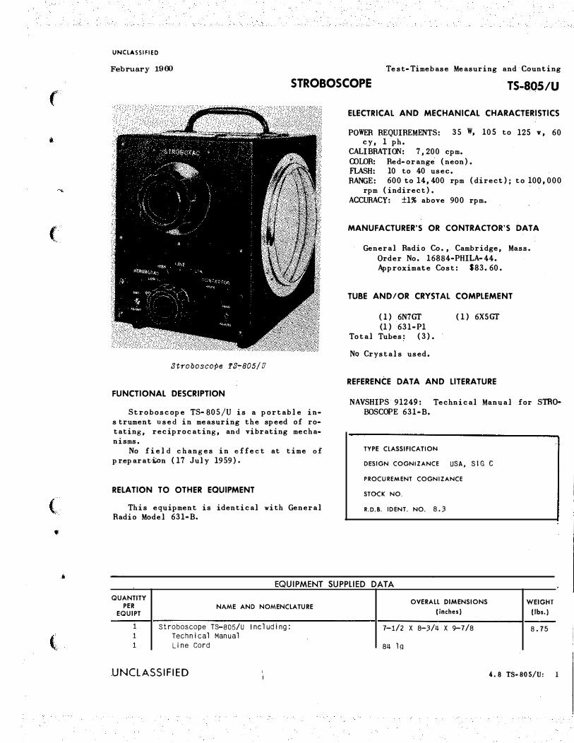
Stroboscope fS�805/U
FUNCTIONAL DESCRIPTION
Stroboscope TS- 805/U is a portable in• s trument used in measuring the speed of ro• tating, reciprocating, and vibrating mecha• nisms.
No field changes in effect at time of pr.eparat�n (17 July 1959).
RELATION TO OTHER EQUIPMENT
This equipment is identical with General Radio Model 631-B •
ELECTRICAL AND MECHANICAL CHARACTERISTICS
POWER REQUIREMENTS: 35 W, 105 to 125 v, 60 cy, 1 ph •
CALIBRATION: 7,200 cpm. COLOR: Red•orange (neon). FLASH: 10 to 40 usee. RA NGE: 600 to 14, 400 rpm (direct); to 100, 000
rpm (indirect) •
ACCURACY: ±1% above 900 rpm.
MANUFACTURER'S OR CONTRACTOR'S DATA
General Radio Co., Cambridge, Mass. Order No. 16884-PHILA-44. Approximate Cost: $83.60.
TUBE AND/OR CRYSTAL COMPLEMENT
(1) 6N7GT (1) 631·P1
Total Tubes: (3).
No Crystals used.
(1) 6X5GT
REFERENCE OAT A AND LITERATURE
NAVSHIPS 91249: Technical Manual for STR� BOSCOPE 631-B.
TYPE CLASSIFICATION
DESIGN COGNIZANCE USA, S I G C
PROCUREMENT COGNIZANCE
STOCK NO.
R.D.B. I DENT. NO. 8. 3
EQUIPMENT SUPPLIED DATA
QUANTITY PER
EQUIPT
1 1 1
NAME AND NOMENCLATURE
Stroboscope TS-805/U Including: Technical Manual
Line Cord
UNCLASSIFIED
OVERALL DIMENSIONS
(inches)
7-1/2 X 8-3/4 X 9-7/8
84 lq
WEIGHT
(lbs.)
8.75
4. 8 TS·8il5/U: 1
UNCLASSIFIED
February 1960 Test-Timebase Measuring and Counting
STROBOSCOPE TS-805A/U
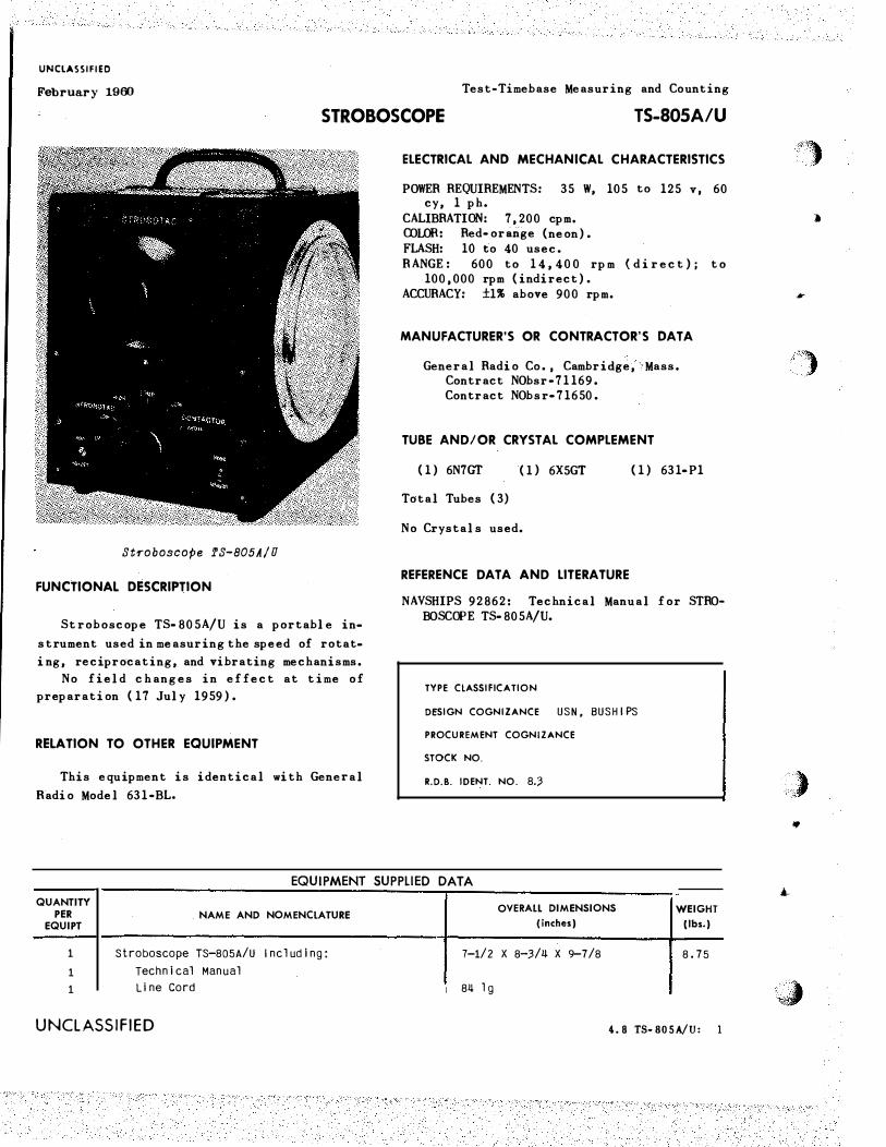
Stroboscope fS-805A/U
FUNCTIONAL DESCRIPTION
S t roboscope TS-805A/U is a portable in
strument used in measuring the speed of rotat•
i ng, reciprocating, and vibrating mechanisms.
No field changes in effect at time of
preparation (17 July 1959).
RELATION TO OTHER EQUIPMENT
This equipment is identical with General
Radio Model 631-BL.
ELECTRICAL AND MECHANICAL CHARACTERISTICS
P OWER REQUIREMENTS: 35 W, 105 to 125 v, 60 cy, 1 ph.
CALIBRATION: 7,200 cpm. COLOR: Red-orange (neon). FLASH: 10 to 40 usee. R A NGE: 600 to 14 ,4 00 rpm (d i r e c t ); to
100,000 rpm (indirect). ACCURACY: ±1% above 900 rpm.
MANUFACTURER'S OR CONTRACTOR'S DATA
General Radio Co., Cambridge, Mass. Contract NObsr-71169. Contract NObsr- 71650.
TUBE AND/OR CRYSTAL COMPLEMENT
(1) 6N7GT (1) 6X5GT (1) 631-P1
Total Tubes ( 3)
No Crystals used.
REFERENCE DATA AND LITERATURE
NAVSH IPS 92862: Technical Manual for STROBOSCOPE TS-805A/U.
TYPE ClASSIFICATION
DESIGN COGNIZANCE USN, BUSH IPS
PROCUREMENT COGNIZANCE
STOCK NO.
R.D.B. IDENT. NO. 8.:3
EQUIPMENT SUPPLIED DATA
QUANTITY PER
EQUIPT
1
1
1
NAME AND NOMENClATURE
Stroboscope TS-805A/U Including:
Technical Manual
Line Cord
UNCLASSIFIED
OVERAlL DIMENSIONS (inches)
7-1/2 X 8-3/4 X 9-7/8
1 84 1 g
WEIGHT (lbs.)
8.75
4. 8 TS-BOSA/U:
''''"'.· , ,
)
I
.)
.', ) •
..
• ·�
(
•
(
( 9),
•
(
18 May 1962 Cog. Service: USN FSN:
STROBOSCOPE TS-969/U Functional Class: 8.3
USA USN USAF
TYPE C LASS: Used by -��
MANUFACTURER'S NAME/CODE NUMBER: Electronic Brazing co., (83�90).
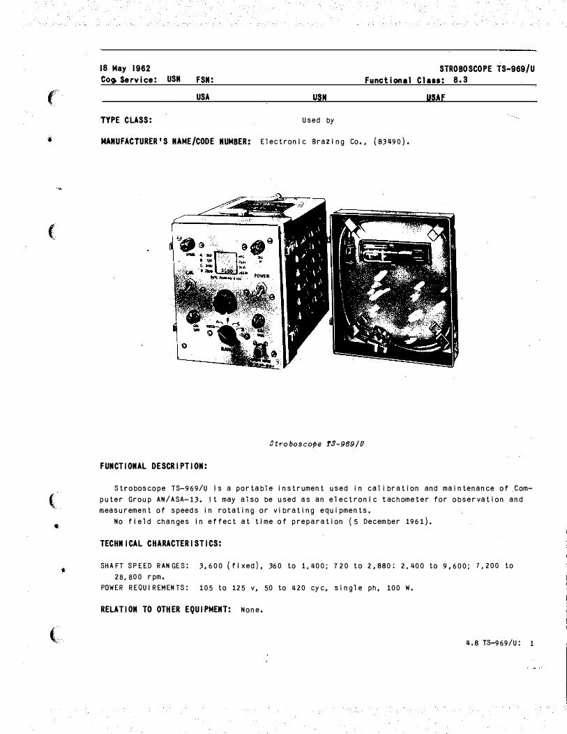
Stroboscope fS-989/U
FUNCTIONAL DESCRIPTION:
Stroboscope TS-969/U Is a portable instrument used in calibration and maintenance of Computer Group AN /ASA-13. It may also be used as an electronic tachometer for observation and measurement of speeds in rotating or vibrating equipments.
No field changes in effect at time of preparation (5 December 1961).
TECHNICAL CHARACTERISTICS:
SHAFT SPEED RANGES: 3,600 (fixed}, 360 to 1,�00; 720 to 2,880: 2,�00 to 9,600; 7,200 to
28,800 rpm. POWER REQUIREMENTS: 105 to 125 v, 50 to � 20 eye, single ph, 100 W.
RELATION TO OTHER EQUIPMENT: None.
�.8 T8-96.9/U: 1
TS-969/U STROBOSCOPE
EQUIPMENT REQUIRED BUT NOT SUPPLIED: None.
QTY ITEM
1 Stroboscope TS-969/U Includes: 1 Case Cover 1 Cable Assy, Power
REFERENCE DATA AND LITERATURE:
MAJOR COMPONENTS
STOCK NUMBERS DI MENSIONS (INCHES)
8-1/8 X 8-3/8 X 1 3-7/8
WEIGHT ( LBS)
20
''�)
)
•
NAVAER 16-35TS969-1 : H andbook of Operations and Service Instructions with Illustrated Parts
'")' Breakdown for Stroboscope TS-969/U. .
TUBE, CRYSTAL AND/OR SEMI-CONDUCTOR DATA:
TUBES: (1) 5V�GA (1) 5687WA (2) 5751 (1) 5965 (2) 6627/0B2WA (2) 6 31-P1
CRYSTALS: None used,
SEMI-CONDUCTORS: None used.
PKGS
PROCURING SERVICE: USN
SHIPPING DATA
VOLUME ( CU FT)
PRO CUREMENT DATA
DESIGN COG: USN, BaWeps SPEC &/OR DWG: MIL-S-18437(BuAer)
CONTRACTOR
Electronic Brazing Co. Part no. 82-100
Loral Electronics Corp. Part no. �501-11
�.8 T$-969/U: 2
LOCATION
Montclair, N. J.
New York, N. Y.
CONTRACT OR ORDER NO.
N 38 3( 17)-5� 53 SA N383-60503A NOas�ss-766-r
WEIG HT (LBS)
APPRO X.
UN IT COST
,) •
•
<,t)
(
•
""
(
\
•
J.
{
UNCLASSIFIED
February 1960 Test-Timebase Measuring and Counting
STROBOSCOPE 60175
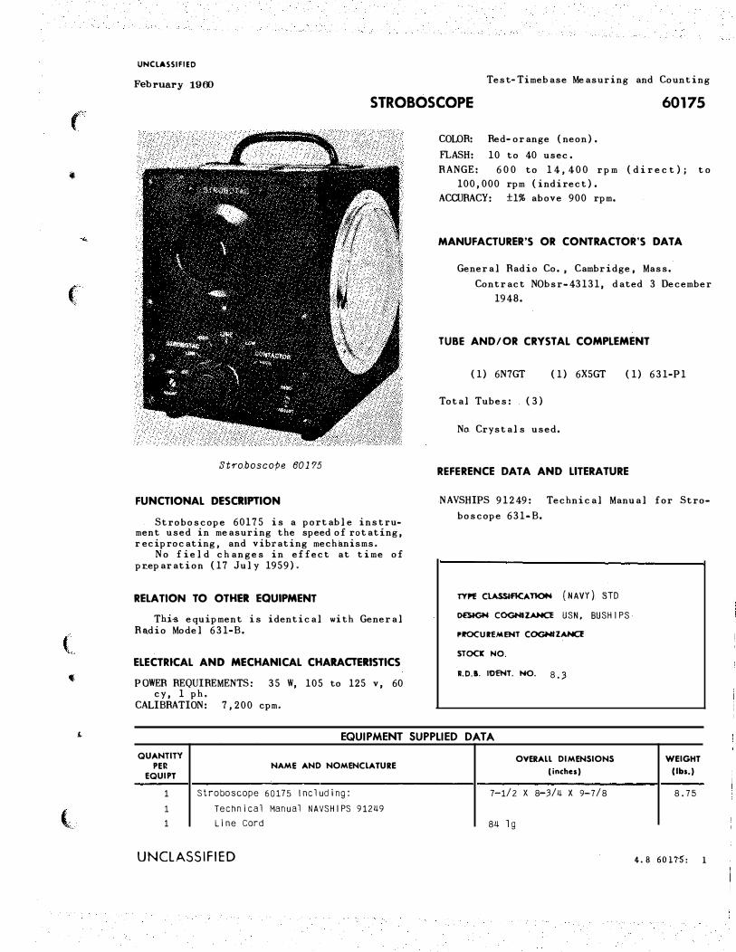
Stro.boscope 60175
FUNCTIONAL DESCRIPTION
Stroboscope 60175 is a portable instrument used in measuring the speed of rotating, r eciprocating, and vibrating mechanisms.
No field changes in effect at time of pr.eparation (17 July 1959).
RELA TJON TO OTHER EQUIPMENT
This equipment is identical with General Radio Model 631-B.
ELECTRtCAL AND MECHANICAL CHARACTERISTICS
POWER REQUIREMENTS: 35 W, 105 to 125 v, 60 cy, 1 ph.
CALIBRATION: 7,200 cpm.
C OLOR: Red-orange (neon).
FLASH: 10 to 40 usee.
R ANGE: 600 to 1 4 , 4 00 rpm (direc t ); to
100,000 rpm (indirect).
ACCURACY: ±1% above 900 rpm.
MANUFACTURER'S OR CONTRACTOR'S DATA
General Radio Co., Cambridge, Mass.
Contract NObsr-43131, dated 3 December
1948.
TUBE AND/OR CRYSTAL COMPLEMENT
(1) 6N7GT (1) 6X5GT ( 1) 631-P1
Total Tubes: ( 3)
No Crystals used.
REFERENCE OAT A AND LITERATURE
NAVSHIPS 91249: Technical Manual for Stro
boscope 631-B.
TYI"E C\.ASSjflCA 1l()IH ( NAVY) S TD
0ES1GH COGNIZANCE USN, BUSH IPS
I'.OCURfMENT COGNIZAHCf
STOCK NO.
R.O.I. IOENT. NO. 8. 3
EQUIPMENT SUPPLIED DATA
QUANTITY PEil
EQUIPT
1 1 1
NAME AND NOMENCLATURE
Stroboscope 60175 Including:
Technical Manual NAVSHIPS 91249 Line cord
UNCLASSIFIED
OVERALL DIMENSIONS (inches)
7-1/2 X 8-3/4 X 9-7/8
84 lg
WEIGHT (lbs.)
8.75
4. 8 6017"5: 1
____ j UNCLASSIFIED
April 1958 Test-Time Base Measuring and Counting
STROBOTAC 631-B (GENERAL RADIO)
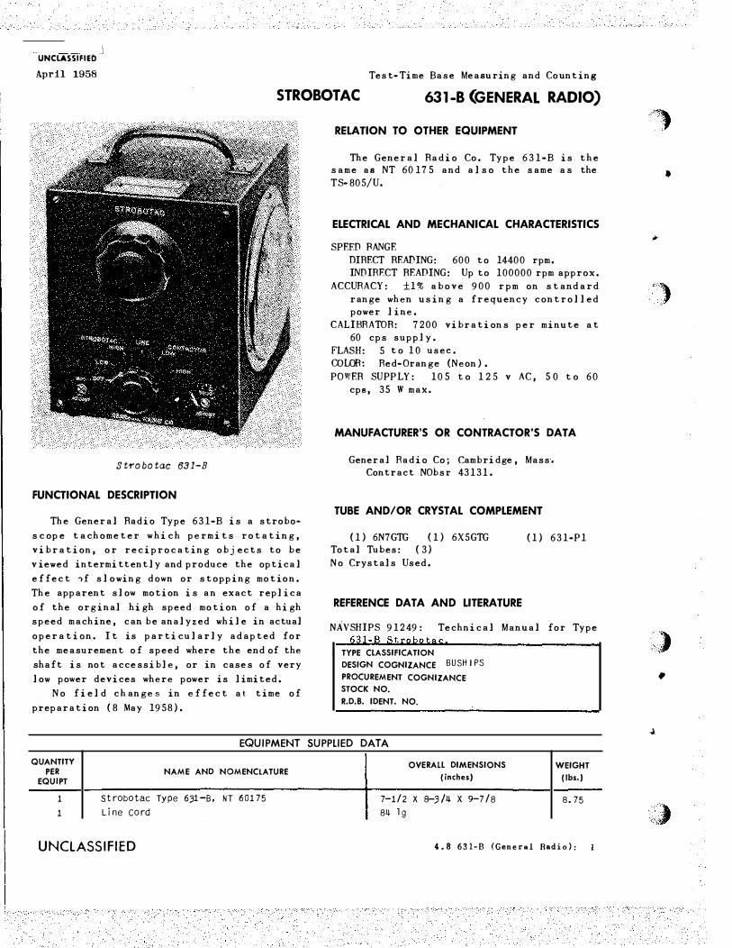
Strobotac 631-B
FUNCTIONAL DESCRIPTION
The General Radio Type 631-B is a strobo
s c ope tachometer w hi c h permits rotating,
vibration, or reciprocating objects to be
viewed intermittently and produce the optical
effect �f slowing down or stopping motion.
The apparent slow motion is an exact replica
of the orginal high speed motion of a high
speed machine, can be analyzed while in actual
operation. I t is particularly adapted for
the measurement of speed where the end of the
shaft is not accessible, or in cases of very
low power devices where power is limited.
No field changes in effect at time of
preparation ( 8 May 1958).
RELATION TO OTHER EQUIPMENT
The General Radio Co. Type 631-B is the same as NT 60175 and also the same as the TS-805/U.
ELECTRICAL AND MECHANICAL CHARACTERISTICS
SPEED BANGE
DIRECT READING: 600 to 14400 rpm. INDIRECT READING: Up to 100000 rpm approx.
ACCURACY: ±1% above 900 rpm on standard
range when using a frequency controlled power line.
CALIBRATOR: 7200 vibration s per minute at 60 cps supply.
FLASH: 5 to 10 usee.
COLOR: Red-Orange (Neon ) .
P OWER SUPP LY: 105 t o 1 2 5 v AC, 5 0 t o 60 cps, 35 W max.
MANUFACTURER'S OR CONTRACTOR'S DATA
General Radio Co; Cambridge, Mass.
Contract NObsr 43131.
TUBE AND/OR CRYSTAL COMPLEMENT
(1) 6N7GTG (1) 6X5GTG Total Tubes: ( 3)
No Crystals Used.
REFERENCE DATA AND LITERATURE
(1) 631-P1
NAVSHIPS 91249: Technical Manual for Type
631-B Strobotac TYPE CLASSIFICATION
DESIGN COGNIZANCE BUSH IPS
PROCUREMENT COGNIZANCE STOCK NO.
R.D.B. IDENT. NO.
EQUIPMENT SUPPLIED DATA
QUANTITY PER
EQUIPT
1 1
NAME AND NOMENCLATURE
Strobotac Type 6)1-B, NT 60175 Line cord
UNCLASSIFIED
OVERALL DIMENSIONS
(inches)
7-1/2 X B-3/4 X 9-7/8 84 lg
WEIGHT
(lbs.)
8.75
4.8 631-B (General Radio):
?�
•
,
')
·� ;·:.LI
•
�
.. ·.·� 'A:�