Embed Size (px)
Citation preview
Document No: UTC-4702.SLP Revision Date: 14.10.2019
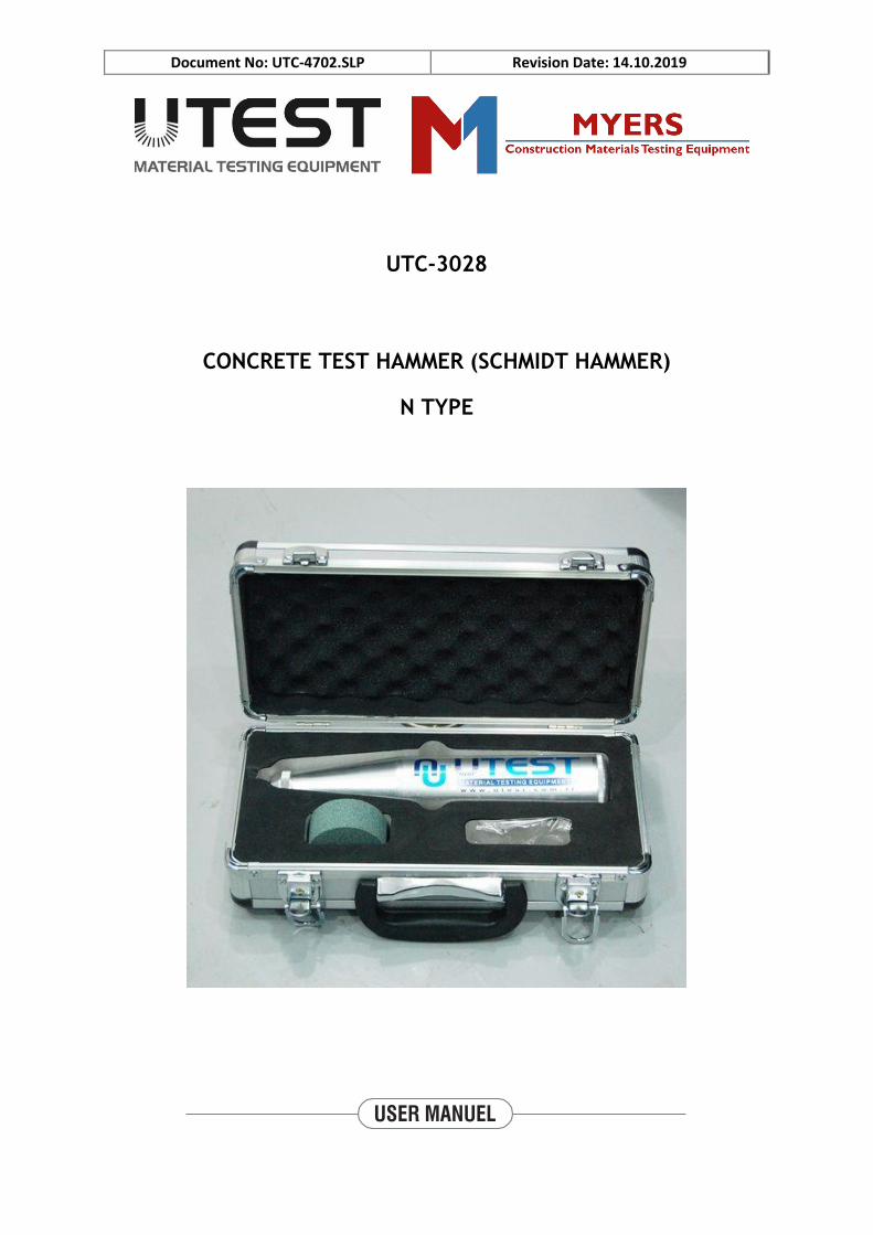
UTC-3028
CONCRETE TEST HAMMER (SCHMIDT HAMMER)
N TYPE
Document No: UTC-4702.SLP Revision Date: 14.10.2019
CONTENT
LIABILITY & SAFETY ............................................................................................................. i
Safety Symbols and Markings ..................................................................................................... i
Liability ....................................................................................................................................... i
General Safety Instructions ........................................................................................................ ii
Device Handling ........................................................................................................................ iii
1. INTRODUCTION .................................................................................................................. 1
1.1 Product Description .......................................................................................................... 1
1.2 Units of the Device ........................................................................................................... 2
2. INSTALLATION ................................................................................................................... 3
2.1 Environment ..................................................................................................................... 3
2.2 Unpacking ........................................................................................................................ 3
3. OPERATION ......................................................................................................................... 3
4. CHART READING ............................................................................................................... 6
5. CALIBRATION PROCEDURE ............................................................................................ 6
6. MAINTANENCE ................................................................................................................... 7
6.1 Cleaning of the Device ................................................................................................ 8
7. DECLERATION ............................................................................................................... 12
8. CONTACT INFORMATION .............................................................................................. 13
Document No: UTC-4702.SLP Revision Date: 14.10.2019
FIGURES
Figure 1: Set of UTC-3028 ......................................................................................................... 1
Figure 2: Parts of the UTC-3028 ................................................................................................ 2
Figure 3: Button and Conversion Curve .................................................................................... 4
Figure 4: Scale ............................................................................................................................ 5
Figure 5: Conversion Chart ........................................................................................................ 5
Figure 6: Calibration Anvil (UTC-3040E) ................................................................................. 6
Figure 7: Two Parts Ring ........................................................................................................... 8
Figure 8: Compression Spring and Cover .................................................................................. 8
Figure 9: System and Strike Direction to Remove Impact Plunger ........................................... 8
Figure 10: Impact Plunger and Retaining Spring ....................................................................... 9
Figure 11: Hammer Mass, Hammer Guide Bar, Impact Spring, and Sleeve ............................. 9
Figure 12: The System in the Housing ..................................................................................... 10
TABLES
Tablo 1: Name of the Parts ......................................................................................................... 2
Document No: UTC-4702.SLP Revision Date: 14.10.2019
i
LIABILITY & SAFETY
This manual contains important information on the safe usage and maintenance of UTC-3028
Concrete Test Hammer (Schmidt Hammer) N Type and of its related components. Please read
through the manual carefully before operating the device for the first time and keep it for the
future reference.
Liability
UTEST General Terms and Conditions of Sales and Delivery apply in all cases. Warranty and
liability claims arising from personal injury and damage to property cannot be upheld if they
are due to one or more of the following causes:
Unauthorized modifications to the device and its components.
Failure to use the instrument in accordance with its designated use and purpose which
is described in this manual.
Failure to adhere to the sections of the manual dealing with the performance check,
operation and maintenance of the instrument and its components.
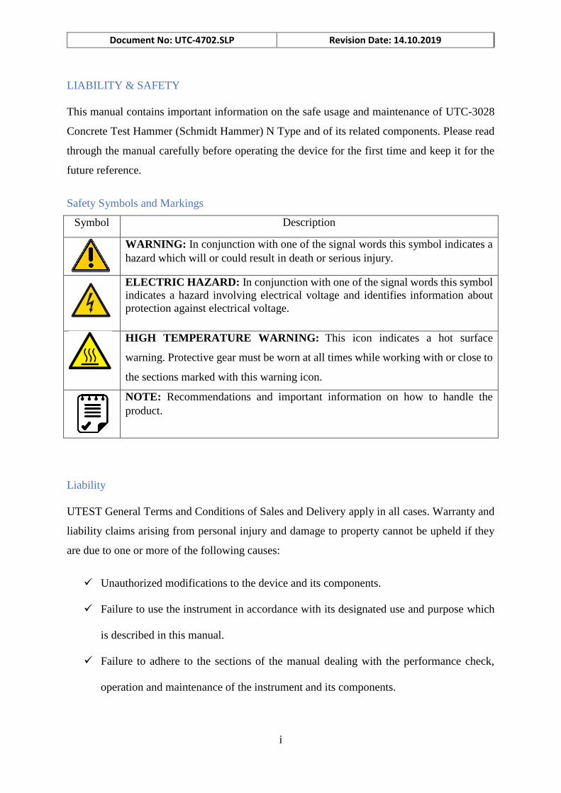
Safety Symbols and Markings
Symbol Description
WARNING: In conjunction with one of the signal words this symbol indicates a
hazard which will or could result in death or serious injury.
ELECTRIC HAZARD: In conjunction with one of the signal words this symbol
indicates a hazard involving electrical voltage and identifies information about
protection against electrical voltage.
HIGH TEMPERATURE WARNING: This icon indicates a hot surface
warning. Protective gear must be worn at all times while working with or close to
the sections marked with this warning icon.
NOTE: Recommendations and important information on how to handle the
product.
Document No: UTC-4702.SLP Revision Date: 14.10.2019
ii
Incorrect performance checks for operation and maintenance of the instrument and its
components.
Damage resulting from the effects of foreign bodies, accidents, vandalism and force
majeure.
The instrument is only to be used for its designated purpose as describe herein. Replace faulty
components only with original replacement parts from UTEST. Accessories should only be
installed or connected to the instrument if they are expressly authorized by UTEST. If other
accessories are installed or connected to the instrument, then UTEST will accept no liability
and the product guarantee is forfeit.
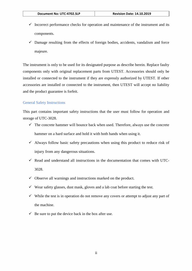
General Safety Instructions
This part contains important safety instructions that the user must follow for operation and
storage of UTC-3028.
The concrete hammer will bounce back when used. Therefore, always use the concrete
hammer on a hard surface and hold it with both hands when using it.
Always follow basic safety precautions when using this product to reduce risk of
injury from any dangerous situations.
Read and understand all instructions in the documentation that comes with UTC-
3028.
Observe all warnings and instructions marked on the product.
Wear safety glasses, dust mask, gloves and a lab coat before starting the test.
While the test is in operation do not remove any covers or attempt to adjust any part of
the machine.
Be sure to put the device back in the box after use.
Document No: UTC-4702.SLP Revision Date: 14.10.2019
iii
WARNING: The equipment is not allowed to be operated by children or anyone under
the influence of alcohol, drugs or pharmaceutical preparations. Anyone who is not
familiar with this manual must be supervised when using the equipment. Carry out the
stipulated maintenance properly and at the correct time. Following completion of the
maintenance tasks, perform a functional check.
Device Handling
The electronic parts and other parts of UTC-30283 are sensitive components. Please handle
them carefully.
Do not place any heavy objects on the device.
Avoid any impact or rough handling that might damage the device or the cells.
Do not disassemble UTC-3028.
WARNING: Consult the authorized technical service personnel for disassembly and
reassembly.
Document No: UTC-4702.SLP Revision Date: 14.10.2019
1
1. INTRODUCTION
1.1 Product Description
The quality of concrete is mainly judged by its compressive strength directly affecting the load-
bearing capacity and durability of concrete structures.
UTC-3028 Concrete Test Hammer (Schmidt Hammer N Type) is used to measure the
compressive strength characteristics of hardened concrete non-destructively, control uniform
concrete quality and detect weak spots in the concrete. UTC-3028 Concrete Test Hammer is
the results of continuous research to upgrade the testing machines with the latest technologies
to conform to the latest standards TS EN 12504-2, 13791; ASTM C 805; BS 1881:202; NF
P18-417; DIN 1048; UNI 9189 in terms of its technical properties taking into account client
requirements.
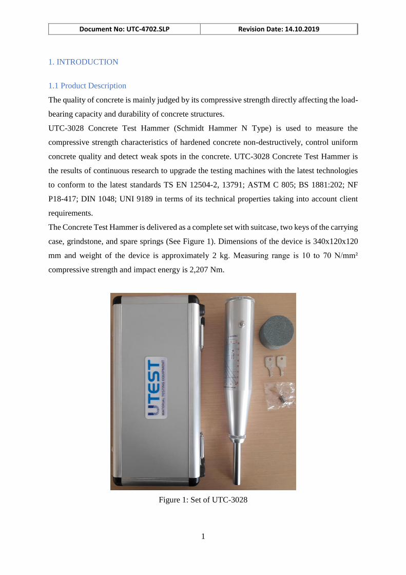
The Concrete Test Hammer is delivered as a complete set with suitcase, two keys of the carrying
case, grindstone, and spare springs (See Figure 1). Dimensions of the device is 340x120x120
mm and weight of the device is approximately 2 kg. Measuring range is 10 to 70 N/mm²
compressive strength and impact energy is 2,207 Nm.
Figure 1: Set of UTC-3028
Document No: UTC-4702.SLP Revision Date: 14.10.2019
2
The Concrete Hammer is the result of a perfectioning of this ancient testing system. As the
Impact Plunger is pressed against the surface that is to be tested, a spring is loaded. When the
Impact Plunger has disappeared inside the Concrete Hammer completely, a mass is
automatically released that strikes the rod itself on the internal end and, through this, the surface
of the concrete. The Impact Plunger reacts and re-transmits the rebound to the mass: the harder
and the more compact the concrete, the greater the rebound. During the rebound stroke, the
mass moves a pointer that indicates the maximum point of return and at the same time indicates
a reference value on the scale. This number, when translated to the chart on the concrete
hammer, gives the compression resistance value in respect of the impact angle.
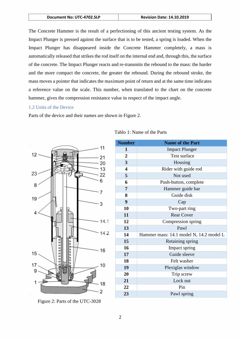
Parts of the device and their names are shown in Figure 2.
Tablo 1: Name of the Parts
1.2 Units of the Device
Number Name of the Part
1 Impact Plunger
2 Test surface
3 Housing
4 Rider with guide rod
5 Not used
6 Push-button, complete
7 Hammer guide bar
8 Guide disk
9 Cap
10 Two-part ring
11 Rear Cover
12 Compression spring
13 Pawl
14 Hammer mass: 14.1 model N, 14.2 model L
15 Retaining spring
16 Impact spring
17 Guide sleeve
18 Felt washer
19 Plexiglas window
20 Trip screw
21 Lock nut
22 Pin
23 Pawl spring
Figure 2: Parts of the UTC-3028
Document No: UTC-4702.SLP Revision Date: 14.10.2019
3
2. INSTALLATION
2.1 Environment
Make sure that the device is placed in a clean and dry surrounding. Direct contact of the device
with the sunlight should be avoided. A conditioned room for example, will comply the above
conditions and will result in best operational performance and measurement results. Device
should be well accessible for testing and maintenance.
In order to prevent inaccurate test results, the ground should be rigid enough to minimize
vibrations or shocks. If there are any other testing equipment or a source that creates vibrations
on the floor, device should be placed maximum possible distance to that source. Surface of the
ground should be horizontal and smooth enough so that the horizontal and vertical alignment
of the device are not shifted.
2.2 Unpacking
Open the case without damaging the contents and remove all packaging materials. Check for
completeness and damages if exist. Report any irregularities directly to the supplier. Take
necessary precautions and carefully transport and place the device to its place.
3. OPERATION
The device measures the rebound value R. There is a specific relationship between this value
and the hardness and strength of the concrete.
The following factors must be taken into account when ascertaining rebound values R:
Impact direction: horizontal, vertically upwards or downwards
Age of the concrete
Size and shape of the comparison sample (cube, cylinder)
Model N can be used for testing:
Concrete items 100 mm or more in thickness
Concrete with a maximum particle size 32 mm
NOTE: During testing, keep test hammer perpendicular to test surface.
NOTE: Preferably perform measurements at temperatures between 10°C and 50°C only.
Document No: UTC-4702.SLP Revision Date: 14.10.2019
4
Operation procedure as follows:
1. Generally, Test Hammer was locked during storage, so it should be unlocked it before
a test. To unlock Test Hammer, take out test hammer, keeping the Impact Plunger
perpendicular to a surface (any hard). Pushing test hammer on end cover slowly, the
Hammer will unlock and the Button will bound out, stop pushing, removing the Test
Hammer away from the surface, impact plunger will reach out, and at the same time the
hammer mass will be hooked because of the pushing from compression spring, now it
is ready for a test.
2. Test must be performed on smooth and uniform surface. Avoid uneven and porous
surfaces, lumps of gravel and joints in the concrete. Before testing, use the supplied
grindstone to smooth the surface to be tested. Grind the surface with grindstone in a
circular motion until smooth.
3. Aim at the test point, keep perpendicular, push slowly, impact plunger will be pushed
into the Test Hammer, at the same time the compressing spring get compressed, but the
impact spring get stretch and upright. After that the trapped springs release the hammer
to a certain value and strike the surface.
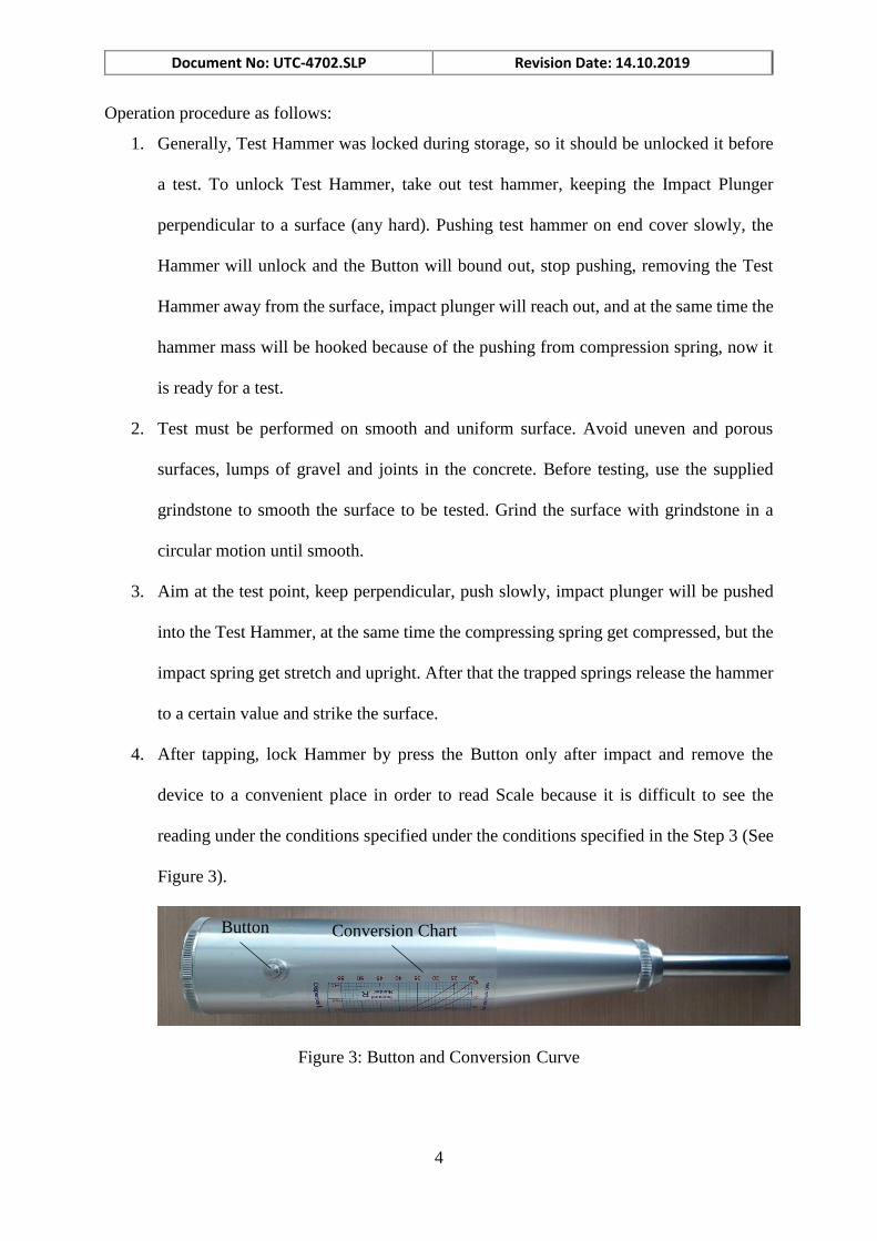
4. After tapping, lock Hammer by press the Button only after impact and remove the
device to a convenient place in order to read Scale because it is difficult to see the
reading under the conditions specified under the conditions specified in the Step 3 (See
Figure 3).
Figure 3: Button and Conversion Curve
Button Conversion Chart
Document No: UTC-4702.SLP Revision Date: 14.10.2019
5
Figure 4: Scale
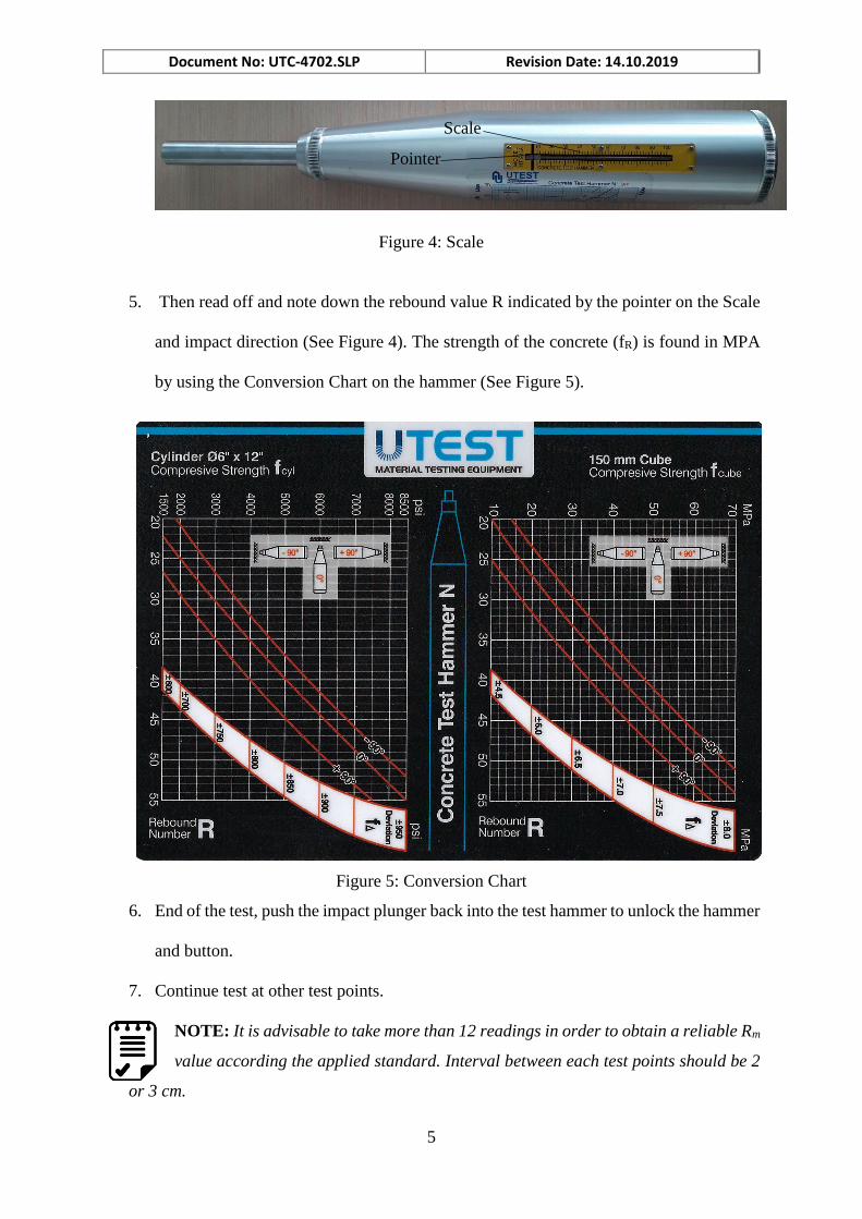
5. Then read off and note down the rebound value R indicated by the pointer on the Scale
and impact direction (See Figure 4). The strength of the concrete (fR) is found in MPA
by using the Conversion Chart on the hammer (See Figure 5).
Figure 5: Conversion Chart
6. End of the test, push the impact plunger back into the test hammer to unlock the hammer
and button.
7. Continue test at other test points.
NOTE: It is advisable to take more than 12 readings in order to obtain a reliable Rm
value according the applied standard. Interval between each test points should be 2
or 3 cm.
Scale
Pointer
Document No: UTC-4702.SLP Revision Date: 14.10.2019
6
NOTE: Do not include values which are too high or too low (the lowest and
highest values) in your calculation of the average value.
8. Just like above test procedure after the impact plunger impact, press the button and the
lock test hammer and note down the rebound value R.
9. Clear test hammer and put back suitcase.
4. CHART READING
To calculate the strength of the concrete, one must record the reading on the Scale. After finding
Rm value on the abscissa then rise vertically up the graph until one of the curves that crosses
the graph diagonally is touched. These cross curves indicate the angle at which the test is
performed. If the test is performed upwards and at an angle of 90° degrees to the surface, the
intersection with the curve marked +90° should be determined. If the test was performed in the
horizontal direction, the intersection with the curve in the middle should be ensured. If the test
is carried out downwards and at a -90° degree to the surface, the intersection with the curve
labeled -90° should be determined. At the point of intersection, one moves horizontally to the
left until the ordinate is touched. This ordinate indicates strength values in MPa.
If the Mpa value on the chart is to be converted to psi, the Mpa value must be multiplied by
145.0377. Likewise, if Mpa is to be converted to kgf/cm2, then Mpa should be multiplied by
10.1972.
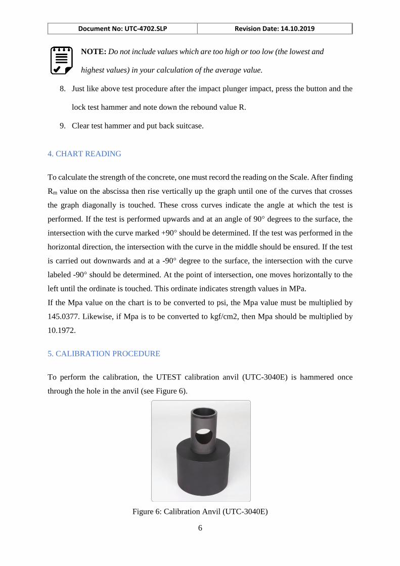
5. CALIBRATION PROCEDURE
To perform the calibration, the UTEST calibration anvil (UTC-3040E) is hammered once
through the hole in the anvil (see Figure 6).
Figure 6: Calibration Anvil (UTC-3040E)
Document No: UTC-4702.SLP Revision Date: 14.10.2019
7
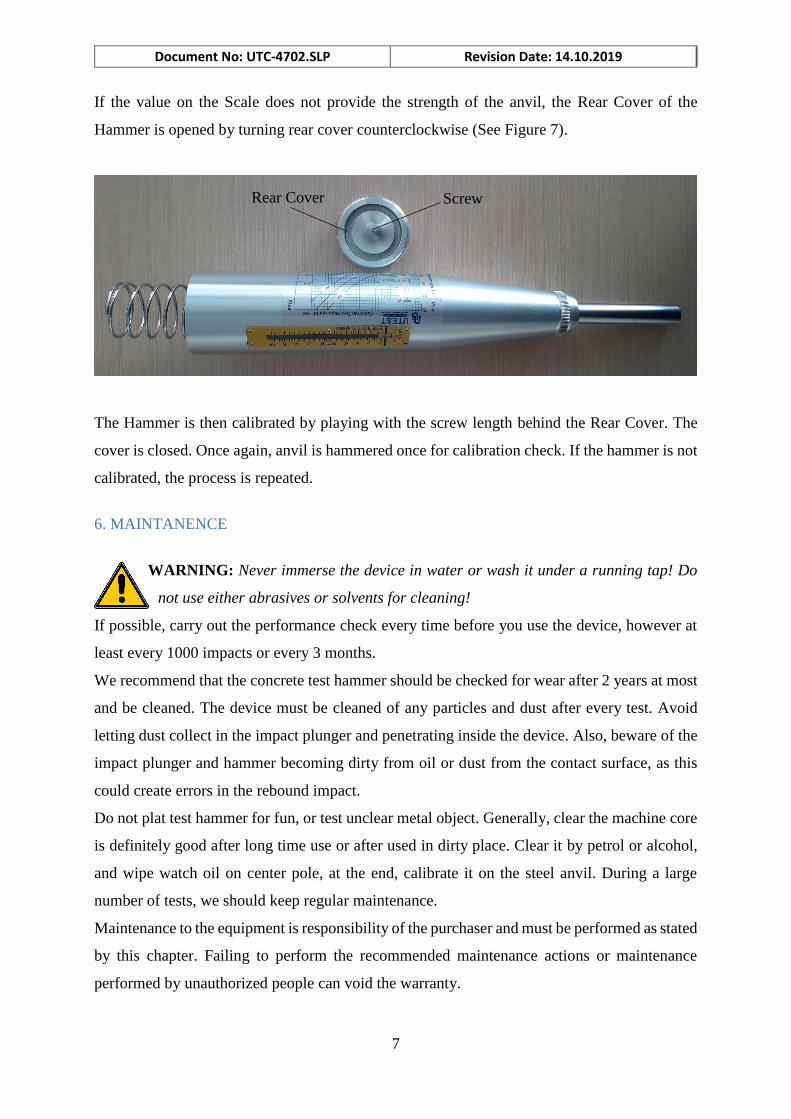
If the value on the Scale does not provide the strength of the anvil, the Rear Cover of the
Hammer is opened by turning rear cover counterclockwise (See Figure 7).
The Hammer is then calibrated by playing with the screw length behind the Rear Cover. The
cover is closed. Once again, anvil is hammered once for calibration check. If the hammer is not
calibrated, the process is repeated.
6. MAINTANENCE
WARNING: Never immerse the device in water or wash it under a running tap! Do
not use either abrasives or solvents for cleaning!
If possible, carry out the performance check every time before you use the device, however at
least every 1000 impacts or every 3 months.
We recommend that the concrete test hammer should be checked for wear after 2 years at most
and be cleaned. The device must be cleaned of any particles and dust after every test. Avoid
letting dust collect in the impact plunger and penetrating inside the device. Also, beware of the
impact plunger and hammer becoming dirty from oil or dust from the contact surface, as this
could create errors in the rebound impact.
Do not plat test hammer for fun, or test unclear metal object. Generally, clear the machine core
is definitely good after long time use or after used in dirty place. Clear it by petrol or alcohol,
and wipe watch oil on center pole, at the end, calibrate it on the steel anvil. During a large
number of tests, we should keep regular maintenance.
Maintenance to the equipment is responsibility of the purchaser and must be performed as stated
by this chapter. Failing to perform the recommended maintenance actions or maintenance
performed by unauthorized people can void the warranty.
Screw Rear Cover
Document No: UTC-4702.SLP Revision Date: 14.10.2019
8
NOTE: Send in the device for repair if the maintenance you perform does not result
in correct function and achievement of the calibration values specified on the testing
anvil.
6.1 Cleaning of the Device
Before cleaning the device in detail, we must disassemble it. This process is described in the
following section:
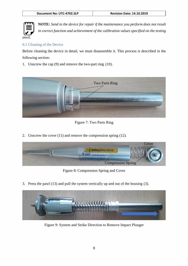
1. Unscrew the cap (9) and remove the two-part ring (10).
Figure 7: Two Parts Ring
2. Unscrew the cover (11) and remove the compression spring (12).
Figure 8: Compression Spring and Cover
3. Press the pawl (13) and pull the system vertically up and out of the housing (3).
Figure 9: System and Strike Direction to Remove Impact Plunger
Two Parts Ring
Cover
Compression Spring
Document No: UTC-4702.SLP Revision Date: 14.10.2019
9
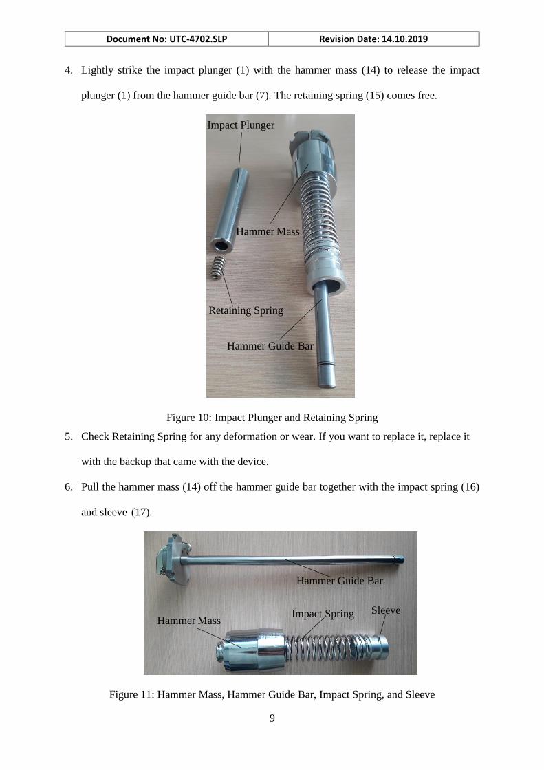
4. Lightly strike the impact plunger (1) with the hammer mass (14) to release the impact
plunger (1) from the hammer guide bar (7). The retaining spring (15) comes free.
Figure 10: Impact Plunger and Retaining Spring
5. Check Retaining Spring for any deformation or wear. If you want to replace it, replace it
with the backup that came with the device.
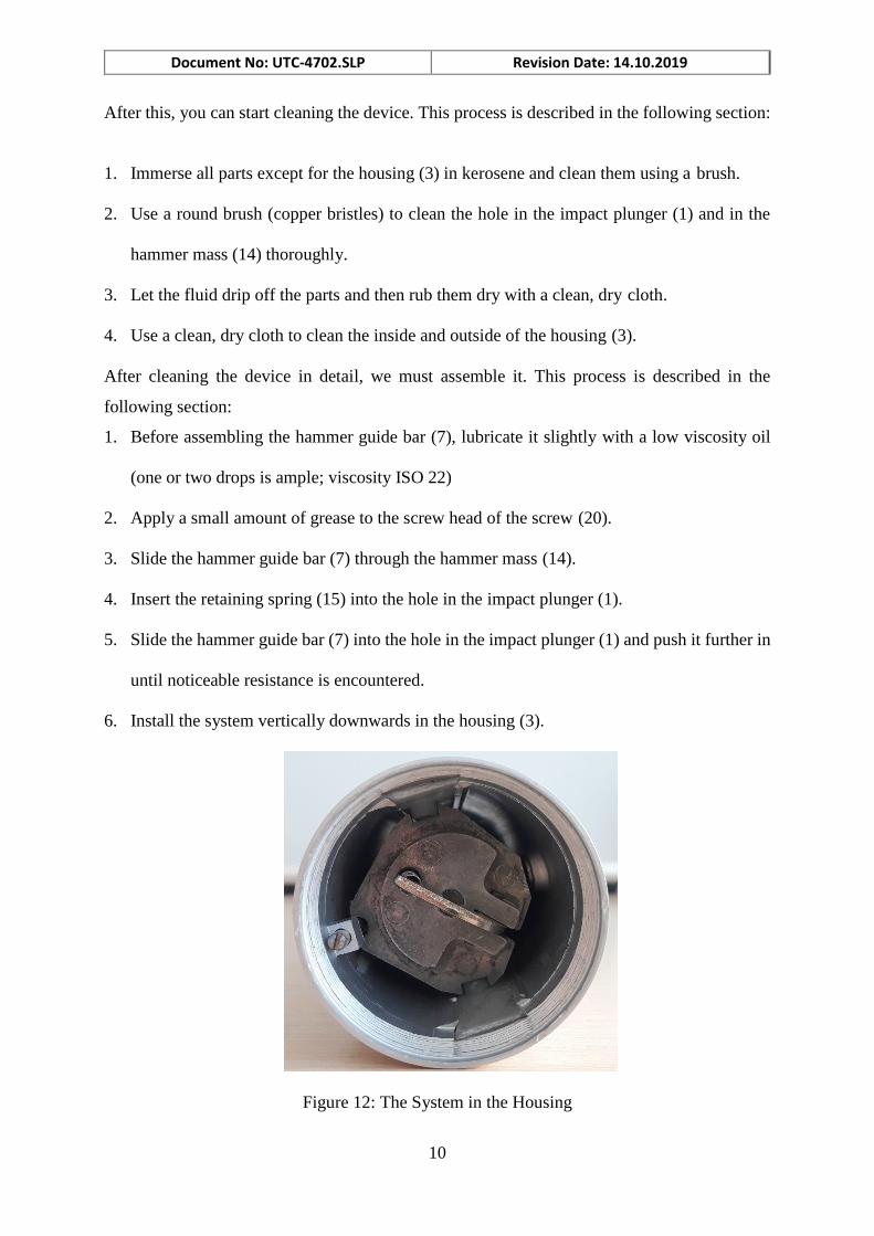
6. Pull the hammer mass (14) off the hammer guide bar together with the impact spring (16)
and sleeve (17).
Figure 11: Hammer Mass, Hammer Guide Bar, Impact Spring, and Sleeve
Impact Plunger
Retaining Spring
Sleeve Impact Spring
Hammer Guide Bar
Hammer Mass
Hammer Guide Bar
Hammer Mass
Document No: UTC-4702.SLP Revision Date: 14.10.2019
10
After this, you can start cleaning the device. This process is described in the following section:
1. Immerse all parts except for the housing (3) in kerosene and clean them using a brush.
2. Use a round brush (copper bristles) to clean the hole in the impact plunger (1) and in the
hammer mass (14) thoroughly.
3. Let the fluid drip off the parts and then rub them dry with a clean, dry cloth.
4. Use a clean, dry cloth to clean the inside and outside of the housing (3).
After cleaning the device in detail, we must assemble it. This process is described in the
following section:
1. Before assembling the hammer guide bar (7), lubricate it slightly with a low viscosity oil
(one or two drops is ample; viscosity ISO 22)
2. Apply a small amount of grease to the screw head of the screw (20).
3. Slide the hammer guide bar (7) through the hammer mass (14).
4. Insert the retaining spring (15) into the hole in the impact plunger (1).
5. Slide the hammer guide bar (7) into the hole in the impact plunger (1) and push it further in
until noticeable resistance is encountered.
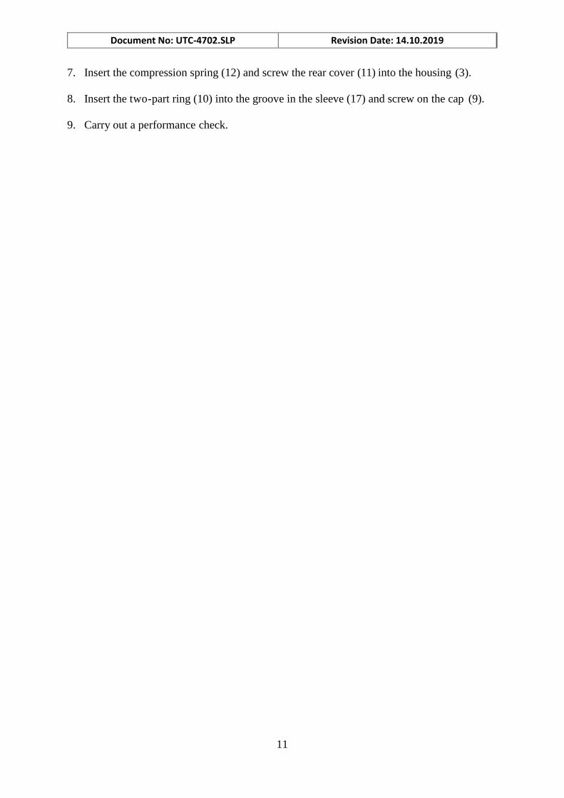
6. Install the system vertically downwards in the housing (3).
Figure 12: The System in the Housing
Document No: UTC-4702.SLP Revision Date: 14.10.2019
11
7. Insert the compression spring (12) and screw the rear cover (11) into the housing (3).
8. Insert the two-part ring (10) into the groove in the sleeve (17) and screw on the cap (9).
9. Carry out a performance check.
Document No: UTC-4702.SLP Revision Date: 14.10.2019
12
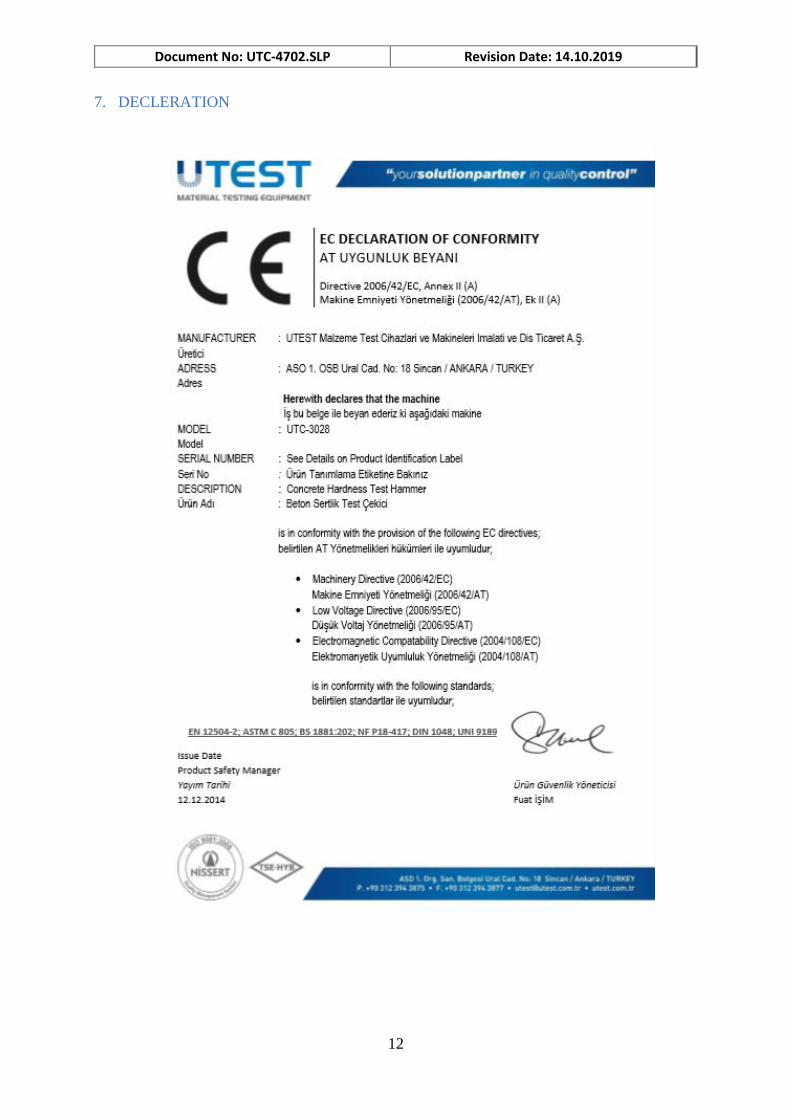
7. DECLERATION

Document No: UTC-4702.SLP Revision Date: 14.10.2019
13
8. CONTACT INFORMATION
21 Washington Avenue, Scarborough, ME [email protected] | 888.293.2121 | www.myerstest.com