Embed Size (px)
Citation preview
FIRE AND RESCUE DEPARTMENTS OF NORTHERN VIRGINIA
FIREFIGHTING AND EMERGENCY OPERATIONS MANUAL
UTILITY
EMERGENCIES
Second Edition
Issued: February 2008 Revised: April 2014
Utility Emergencies, Second Edition Final Version, April 2014
ii
ACKNOWLEDGMENTS
This document was developed through a cooperative effort of the following Northern Virginia
fire departments:
City of Alexandria
Arlington County
City of Fairfax
Fairfax County
Fauquier County
Fort Belvoir
Fort Myer
Loudoun County
City of Manassas
Marine Corps Base Quantico
Metropolitan Washington Airports
Authority (MWAA)
Prince William County
Stafford County
The Northern Virginia Fire Operations Board managed the development of the first edition of the
manual (released in 2008) and the current second edition. The first edition content was
developed by the Operations Board’s Technical Writing Group. The following members of the
Firefighting and Emergency Operations Technical Writing Workgroup participated in the
revision of the manual in 2013/2014:
City of Alexandria: Lieutenant Dave Bogozi, Lieutenant Matthew Craig
City of Manassas: Battalion Chief Mark Nary
Arlington County: Captain David Santini, Lieutenant Nick Krechting
Fairfax City: Captain Joseph Schumacher, Captain Gregory Thuot
Fairfax County: Battalion Chief Tyrone Harrington, Captain David Barlow, and Captain Dan
Shaw
Fort Belvoir: Lieutenant Kevin Good
Fort Myer: Captain William Long
Loudoun County: Lieutenant Scott Lantz
MWAA: Captain Chris Gavurnik, Captain Jason Graber
Prince William County: Captain Frank Orefice, Lieutenant Bryan Ross
Stafford County: Lieutenant Brian Thompson
The following provided sources of information for this manual (both editions):
Dominion Virginia Power, Washington Gas Company, and Pacific Gas and Electric Company
Frank C. Montagna, “Natural Gas Hazards,” Fire Engineering, November 2004
Charlottesville (Virginia) Fire Department
Hildebrand and Noll, Propane Emergencies, 2nd Edition
Frank C. Montagna, Chicago FD, Responding to CO Detector Activations
Northwestern Energy, Safety Information for Emergency Responders
The committee would like to thank the following individuals and organizations for their help in
the development of this manual:
AAW Publication Services: Andrea A. Walter (editing and layout for first and second editions)
Utilities Emergencies, Second Edition Final Version, April 2014
iii
TABLE OF CONTENTS
PREFACE ...................................................................................................................................... 1
DEFINITIONS .............................................................................................................................. 2
Additional Terminology Notes ................................................................................................... 4
OVERVIEW .................................................................................................................................. 5
VIRGINIA UTILITY MARKING STANDARDS ..................................................................... 6
APWA Color Codes .................................................................................................................... 6
NATURAL GAS (METHANE) ................................................................................................... 8
Natural Gas Emergencies ............................................................................................................ 9
Flexible Gas Line ...................................................................................................................... 11
Shut Off for Natural Gas ........................................................................................................... 12
Positioning ................................................................................................................................ 13
Outside Gas Leak ...................................................................................................................... 14
Outside Gas Fires ...................................................................................................................... 17
Inside Gas Leaks ....................................................................................................................... 19
Inside Gas Fires......................................................................................................................... 24
Explosion Incidents Where the Building is Not Supplied by Natural Gas ........................... 24
PROPANE ................................................................................................................................... 25
Propane Emergencies ................................................................................................................ 25
Outside Propane Leaks ............................................................................................................. 25
Outside Propane Tank Fire or Tank Exposed to Fire ............................................................... 26
Propane Leaking Inside a Structure .......................................................................................... 27
CARBON MONOXIDE ............................................................................................................. 28
Carbon Monoxide Emergencies ................................................................................................ 28
ELECTRICAL POWER ............................................................................................................ 31
Electrical Emergencies.............................................................................................................. 32
Electrical Distribution ........................................................................................................... 32
Power Plants.......................................................................................................................... 33
Safety ........................................................................................................................................ 35
Positioning ................................................................................................................................ 35
Wires Down .............................................................................................................................. 36
Underground Vaults, Exterior Vaults, Interior Vaults and Substation Incidents ..................... 39
Interstitial Spaces ...................................................................................................................... 41
Structure Fires ........................................................................................................................... 43
Effects on the Body ................................................................................................................... 44
WATER EMERGENCIES ........................................................................................................ 46
Notifications .............................................................................................................................. 46
Utility Emergencies, Second Edition Final Version, April 2014
iv
TABLE OF TABLES
Table 1: OSHA standards for CO exposure. ................................................................................. 30
Table 2: Limit of approach by line voltage. .................................................................................. 35
TABLE OF FIGURES
Figure 1: Transmission of natural gas to users. .............................................................................. 9
Figure 2: Natural gas fire. ............................................................................................................. 10
Figure 3: Pipeline markings. ......................................................................................................... 10
Figure 4: Typical road crossing. ................................................................................................... 11
Figure 5: Gas main where flexible hose has been used. ............................................................... 11
Figure 6: Gas shut off valve. ......................................................................................................... 12
Figure 7: Examples of quarter-turn valves in residential applications. ........................................ 12
Figure 8: An example of a wrench removing a curb valve cover. ................................................ 13
Figure 9: Commercial gas meter. .................................................................................................. 13
Figure 10: The image on the left shows a street valve and the image on the right shows a curb
valve. Street valves should not be used. ....................................................................................... 15
Figure 11: Locating a leak with soapy water. ............................................................................... 16
Figure 12: Outside gas fire. ........................................................................................................... 17
Figure 13: Exposure protection. .................................................................................................... 17
Figure 14: Fire involving the gas meter. ....................................................................................... 18
Figure 15: Coordinated attack of burning gas meter providing protection for shut off at stopcock.
....................................................................................................................................................... 18
Figure 16: Rooftop commercial HVAC units and exposed gas lines. .......................................... 20
Figure 17: Two basic types of gas meters: outside (image on left) and inside (image on right). . 21
Figure 18: Examples of gas vents; the presence of a gas vent on an exterior wall is an indication
of an inside gas meter. .................................................................................................................. 22
Figure 19: Bank of residential meters with one shut off. .............................................................. 23
Figure 20: Curb box located in a yard. ......................................................................................... 24
Figure 21: Grill fire. ...................................................................................................................... 26
Figure 22: BLEVE of a propane tank. .......................................................................................... 27
Figure 23: This apartment building exploded due to the storage of a propane tank on the third
floor. .............................................................................................................................................. 27
Figure 24: Electrical distribution system. ..................................................................................... 33
Figure 25: An electrical substation (left) and primary lines (right). ............................................. 34
Figure 26: Examples of pole (left) and ground (right) transformers. ........................................... 34
Figure 27: Vehicle that has come in contact with electric lines. Note the scorch marks below the
tires. ............................................................................................................................................... 35
Figure 28: Pole numbers. .............................................................................................................. 37
Utility Emergencies, Second Edition Final Version, April 2014
v
Figure 29: Pole fire. ...................................................................................................................... 38
Figure 30: Ground transformer. .................................................................................................... 38
Figure 31: Ground transformer fire............................................................................................... 39
Figure 32: An underground electrical vault; they are commonly filled with water. ..................... 40
Figure 33: This figure shows an older underground electrical vault (left) and a newer one (right).
....................................................................................................................................................... 40
Figure 34: Interstitial space affords a location for the mechanical systems of the building. ........ 41
Figure 35: An example of where interstitial space can be located in a building. ......................... 42
Figure 36: Another example of where interstitial space can be located in a building. ................. 42
Figure 37: Examples showing that entrance doors vary in size to access the interstitial space. .. 43
Figure 38: Example of the interior of an interstitial space. ........................................................... 43
Figure 39: Older homes may still have screw-in fuse style panels. .............................................. 44
Utility Emergencies, Second Edition Final Version, April 2014
1
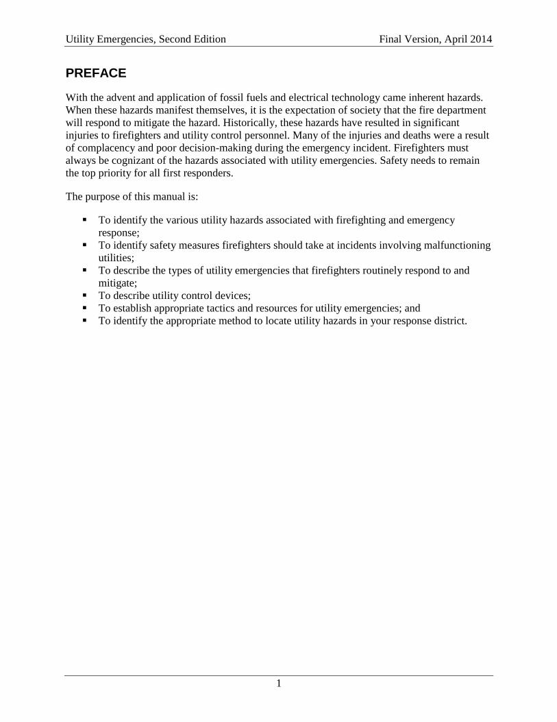
PREFACE
With the advent and application of fossil fuels and electrical technology came inherent hazards.
When these hazards manifest themselves, it is the expectation of society that the fire department
will respond to mitigate the hazard. Historically, these hazards have resulted in significant
injuries to firefighters and utility control personnel. Many of the injuries and deaths were a result
of complacency and poor decision-making during the emergency incident. Firefighters must
always be cognizant of the hazards associated with utility emergencies. Safety needs to remain
the top priority for all first responders.
The purpose of this manual is:
To identify the various utility hazards associated with firefighting and emergency
response;
To identify safety measures firefighters should take at incidents involving malfunctioning
utilities;
To describe the types of utility emergencies that firefighters routinely respond to and
mitigate;
To describe utility control devices;
To establish appropriate tactics and resources for utility emergencies; and
To identify the appropriate method to locate utility hazards in your response district.
Utility Emergencies, Second Edition Final Version, April 2014
2
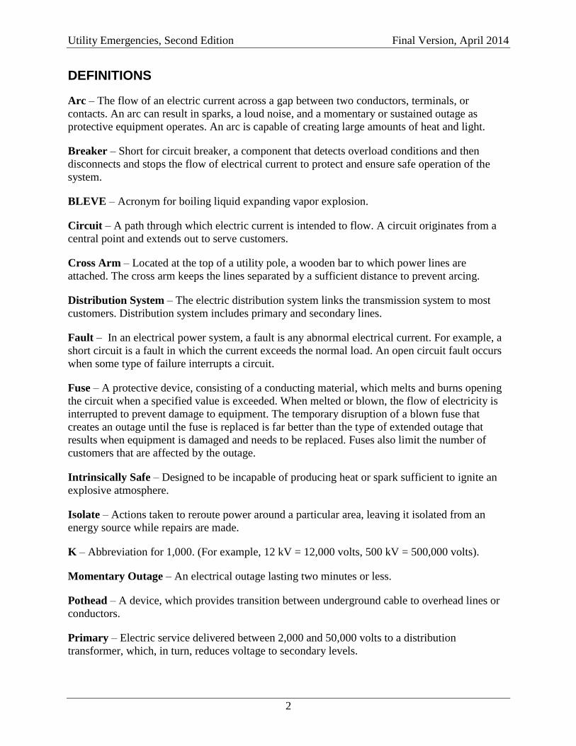
DEFINITIONS
Arc – The flow of an electric current across a gap between two conductors, terminals, or
contacts. An arc can result in sparks, a loud noise, and a momentary or sustained outage as
protective equipment operates. An arc is capable of creating large amounts of heat and light.
Breaker – Short for circuit breaker, a component that detects overload conditions and then
disconnects and stops the flow of electrical current to protect and ensure safe operation of the
system.
BLEVE – Acronym for boiling liquid expanding vapor explosion.
Circuit – A path through which electric current is intended to flow. A circuit originates from a
central point and extends out to serve customers.
Cross Arm – Located at the top of a utility pole, a wooden bar to which power lines are
attached. The cross arm keeps the lines separated by a sufficient distance to prevent arcing.
Distribution System – The electric distribution system links the transmission system to most
customers. Distribution system includes primary and secondary lines.
Fault – In an electrical power system, a fault is any abnormal electrical current. For example, a
short circuit is a fault in which the current exceeds the normal load. An open circuit fault occurs
when some type of failure interrupts a circuit.
Fuse – A protective device, consisting of a conducting material, which melts and burns opening
the circuit when a specified value is exceeded. When melted or blown, the flow of electricity is
interrupted to prevent damage to equipment. The temporary disruption of a blown fuse that
creates an outage until the fuse is replaced is far better than the type of extended outage that
results when equipment is damaged and needs to be replaced. Fuses also limit the number of
customers that are affected by the outage.
Intrinsically Safe – Designed to be incapable of producing heat or spark sufficient to ignite an
explosive atmosphere.
Isolate – Actions taken to reroute power around a particular area, leaving it isolated from an
energy source while repairs are made.
K – Abbreviation for 1,000. (For example, 12 kV = 12,000 volts, 500 kV = 500,000 volts).
Momentary Outage – An electrical outage lasting two minutes or less.
Pothead – A device, which provides transition between underground cable to overhead lines or
conductors.
Primary – Electric service delivered between 2,000 and 50,000 volts to a distribution
transformer, which, in turn, reduces voltage to secondary levels.
Utility Emergencies, Second Edition Final Version, April 2014
3
Recloser – An automatic protection device that senses and interrupts distribution system faults.
Riser – The conductor part of transition leading from underground to overhead; may or may not
include pothead.
Secondary – Electric service taken at less than 2,000 volts. Most residential and business
customers receive electricity from secondary distribution lines.
Sectionalize – The process of opening switches or fuses to divide a circuit into sections to isolate
the cause of the power outage. This reduces the impact of the power outage to the fewest
possible customers by allowing power to move through undamaged parts of the system.
Stopcock Valve – A quarter-turn valve used to restrict or isolate the flow of liquid or gas in a
pipe.
Substation – A location, which uses a collection of transformers to reduce voltage and circuit
breakers to protect circuits.
Sustained Outage – An electrical outage that lasts for more than two minutes.
Switch – A device for making, breaking, or changing connections with in an electric circuit.
Switching – The process of opening and closing switches to isolate an area from the flow of
electricity.
Time Weighted Average (TWA) – The average exposure to a contaminant or condition (such as
noise) to which workers may be exposed without adverse effect over a period such as in an 8-
hour day or 40-hour week.
Transformer – A device, which transforms electric energy from one voltage level to another
level.
Transmission – The transmission system carries electric power at very high voltages, generally
between 60,000 and 500,000 volts. It provides bulk transportation of electricity over long
distances, usually from generating sources to substations for voltage reduction.
Vapor Density – The ratio of the weight of a given volume of gas or vapor to the weight of an
equal volume of air at the same temperature and pressure. A vapor density less than 1 indicates it
is lighter than air and will rise; a vapor density greater than 1 indicates a vapor density heavier
than air and will sink.
V – Abbreviation for volt.
Vault – A space underground for electric cables, transformers, and other parts of the
underground electric system.
Volt – The unit of measure of electric potential, which is the condition that causes electric
energy to flow.
Utility Emergencies, Second Edition Final Version, April 2014
4
Additional Terminology Notes
This manual will discuss the upper explosive limit (UEL) and lower explosive limit (LEL) of
natural gas, propane, and carbon monoxide. Flammable limits are a range of concentrations over
which, a flammable gas or vapor, mixed with air will burn if an ignition source is present. This
range extends between the lower explosive limit (LEL) and the upper explosive limit (UEL).
Below the LEL, the mixture is too lean (or has too much oxygen and not enough fuel)
and cannot burn.
Above the UEL, the mixture is too rich (or has too much fuel and not enough oxygen)
and cannot burn.
Generally, chemicals with a narrow flammable range are less hazardous or less flammable than
those with a broad flammable range. Also, chemicals with a flammable range in the higher
percentages are generally less hazardous or less flammable then those with a flammable range in
the lower percentages.
The term Time Weighted Average (TWA) is used in the carbon monoxide section. An
explanation of the TWA is an average rate of exposure over the course of an eight-hour work
shift. TWA levels are usually lower than ceiling values. Thus, a worker may be exposed to a
level higher than the TWA for part of the day (but still lower than the ceiling value) as long as he
is exposed to levels below the TWA for the rest of the day.
Utility Emergencies, Second Edition Final Version, April 2014
5
OVERVIEW
Utility emergencies comprise a significant amount of our daily call volume. These emergencies
can range anywhere from small-scale natural gas leaks, wires arching, electrical and/or gas odors
to large-scale incidents that will require an expanded Incident Command System to be in place.
Moreover, these incidents may require a single resource to mitigate or require multiple units and
agencies to help ensure a successful outcome. It should be noted that this manual is in no way
intended to guide you through a hazardous materials emergency. This manual is designed to
assist the company officer with decision making and the appropriate actions to take at a utility
emergency until additional resources arrive. A vital resource that should be requested early on is
the assistance from the utility company. These individuals have special equipment and training
that can provide the company officer with the expertise necessary to properly mitigate the
hazard. If you have any doubt concerning your ability to manage an incident involving toxic
gases or leaks request support from a hazardous material response team immediately.
This manual covers common utilities that may be encountered by fire department personnel.
Often times, company officers are tasked with the responsibility of securing utilities. On the
incident scene, when you are given the order to take care of utilities or secure utilities, this
normally refers to the electric and gas utilities. If the incident commander desires any other
utility locked out or secured, they should the identify that utility in the order.
Changes to this version include:
Recommendations mitigating interior vault fires.
Addition of a definitions section to explain terms used within the manual.
Addition of the interstitial space building construction feature.
Defined hazards associated with flexible gas lines.
Additional information on mitigation of downed power line incidents.
New schematics of gas and electrical delivery systems.
Additional information on residential circuit boxes.
Establishment of minimum response complements for gas leaks.
Utility Emergencies, Second Edition Final Version, April 2014
6
VIRGINIA UTILITY MARKING STANDARDS
Damage to underground utilities can cause serious injury, death, and cause major economic
consequences. In order to reduce these occurrences the Virginia State Corporation Commission
approved the American Public Works Association’s (APWA) color codes to mark underground
utilities.
Color-coded surface marks (paint or a similar coating) should be used to indicate the locations
and route of buried lines. To increase visibility, color-coded vertical markers (temporary stakes
or flags) should supplement surface marks.
All marks and markers should indicate the name, initials, or logo of the company that owns or
operates the line and the width of the facility if it is greater than 50 mm (2 inches).
If the surface over the buried line is to be removed supplemental offset markings may be used.
Offset markings should be a uniform alignment and must clearly indicate that the actual facility
is a specific distance away.
The marker types that are most suitable to the terrain and site conditions shall be used. For
example, flags and stakes in landscaped areas, snow, or loose soil. The marker may be as simple
as a color-coded dash line. The color-coded line may also include the size line, owner of line,
product, or the pipeline material. In areas of high traffic the line may be off set with direction
arrows and distance markers.
APWA Color Codes
RED electric, cable, conduit, and lighting cable
YELLOW gas, oil, steam, petroleum, or gaseous materials
ORANGE communications, alarm, or signal lines, cable or conduit
BLUE potable water
PURPLE reclaimed water, irrigation and slurry lines
GREEN sewer and drain lines
PINK temporary survey markings
WHITE proposed excavation
The material type abbreviations are as follows:
CI- cast iron
CPR- copper
DI- ductile iron
PL- plastic
Utility Emergencies, Second Edition Final Version, April 2014
7
PVC-polyvinyl chloride
RFC- reinforced concrete
SCC- steel cylinder concrete
STL- steel
TC- terracotta
TR- transite
W/STL- wrapped steel
The number for contacting Miss Utility is 1-800-552-7001. In Virginia, Miss Utility can also be
accessed by dialing 811.
Utility Emergencies, Second Edition Final Version, April 2014
8
NATURAL GAS (METHANE)
Methane is a simple hydrocarbon consisting of carbon and hydrogen. There are many of these
compounds, and each has its own number of carbon and hydrogen atoms joined together to form
a particular hydrocarbon gas or fuel gas.
Vapor density in gases is defined as the weight of a given volume of gas compared to the weight
of the same amount of air at the same temperature and pressure. Given the factor of one for air,
any gas with a vapor density of less than one will rise and any gas with a vapor density of more
than one will sink in air. Having a vapor density of .55, methane is a very light fuel gas. This means that any escaping natural gas will rise and, if released outdoors, will dissipate
quickly from the site of a leak. There are no toxic components or health hazards associated with
natural gas in wide-open outdoor areas. However, in heavy concentrations, it will displace the
oxygen, causing drowsiness and suffocation from asphyxiation.
Natural gas in its pure state is colorless and odorless. Mercaptan is a pungent odorant that is
added as a safety precaution after it is received at the distribution site. The odorant is so powerful
you can smell even the smallest quantity of gas in the event of a leak. The mercaptan is added at
the distribution site. A note of caution is that natural gas in transmission pipelines and rail cars is
not odorized, so leaks that do occur can go undetected creating a significant danger to first
responders.
The flammable range for natural gas is between 5% and 15 %. This means that any mixture in air
of less than 5% or greater than 15% will not ignite. (Remember, when you have a reading below
5% or above 15% this is the reading only in the specific area you are metering at a reported gas
leak and, at that specific area, it is too rich/too lean to ignite. However, somewhere on the
outside perimeter of the area in which the leak occurred, you may have the proper ignition
range.)
The ignition temperature for natural gas is about 1200° F and can easily be ignited by something
as simple as a doorbell or a cell phone. When operating on the scene of an inside gas leak in
which your monitoring device is activating at LEL/UEL levels proper precautions should be
taken to mitigate this hazard. The primary objective is to control the leak by turning off the gas
to the specific appliance if possible or shutting off the gas to the entire structure. Once the fire
department shuts off the gas to a residence or business it should be tagged appropriately. The fire
department should then ensure that the utility company has been contacted so that the problem
can be corrected before the gas is turned back on. In addition, ventilation should be performed to
remove any gas odors or levels inside the structure. After these steps are taken the firefighters
should repeat the monitoring process to ensure that no hazard exists before turning the scene
over to the property owner. The expansion ratio of liquefied natural gas to a gas is 600:1.This
can create a significant hazard when liquefied gas cylinders are exposed to heat from fire
impingement creating a potential for a BLEVE to occur.
Gas lines typically have operating pressures of 0.25 to 55 pounds per square inch (psi). The
transmission lines range in size from 6” to 30” and have pressures up to 450 psi. These lines can
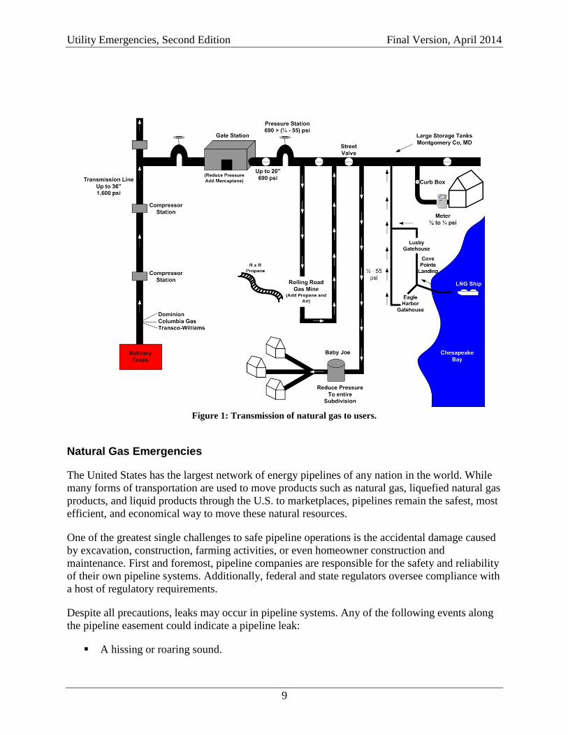
generate 2,000 to 24,000 volts of static electricity. Figure 1 shows the path of natural gas from
wells to users.
Utility Emergencies, Second Edition Final Version, April 2014
9
Figure 1: Transmission of natural gas to users.
Natural Gas Emergencies
The United States has the largest network of energy pipelines of any nation in the world. While
many forms of transportation are used to move products such as natural gas, liquefied natural gas
products, and liquid products through the U.S. to marketplaces, pipelines remain the safest, most
efficient, and economical way to move these natural resources.
One of the greatest single challenges to safe pipeline operations is the accidental damage caused
by excavation, construction, farming activities, or even homeowner construction and
maintenance. First and foremost, pipeline companies are responsible for the safety and reliability
of their own pipeline systems. Additionally, federal and state regulators oversee compliance with
a host of regulatory requirements.
Despite all precautions, leaks may occur in pipeline systems. Any of the following events along
the pipeline easement could indicate a pipeline leak:
A hissing or roaring sound.
Utility Emergencies, Second Edition Final Version, April 2014
10
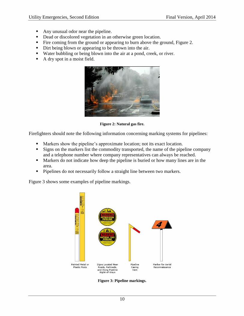
Any unusual odor near the pipeline.
Dead or discolored vegetation in an otherwise green location.
Fire coming from the ground or appearing to burn above the ground, Figure 2.
Dirt being blown or appearing to be thrown into the air.
Water bubbling or being blown into the air at a pond, creek, or river.
A dry spot in a moist field.
Figure 2: Natural gas fire.
Firefighters should note the following information concerning marking systems for pipelines:
Markers show the pipeline’s approximate location; not its exact location.
Signs on the markers list the commodity transported, the name of the pipeline company
and a telephone number where company representatives can always be reached.
Markers do not indicate how deep the pipeline is buried or how many lines are in the
area.
Pipelines do not necessarily follow a straight line between two markers.
Figure 3 shows some examples of pipeline markings.
Figure 3: Pipeline markings.
Utility Emergencies, Second Edition Final Version, April 2014
11
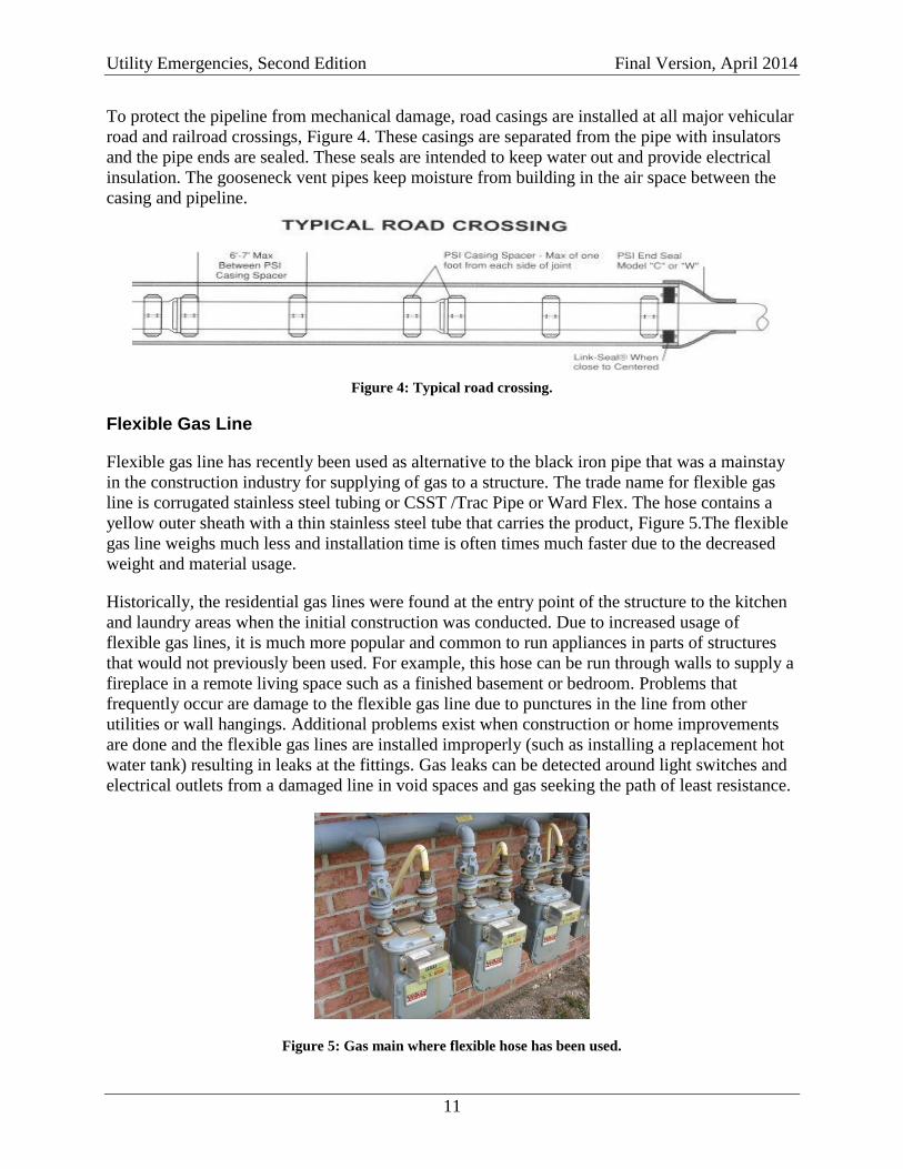
To protect the pipeline from mechanical damage, road casings are installed at all major vehicular
road and railroad crossings, Figure 4. These casings are separated from the pipe with insulators
and the pipe ends are sealed. These seals are intended to keep water out and provide electrical
insulation. The gooseneck vent pipes keep moisture from building in the air space between the
casing and pipeline.
Figure 4: Typical road crossing.
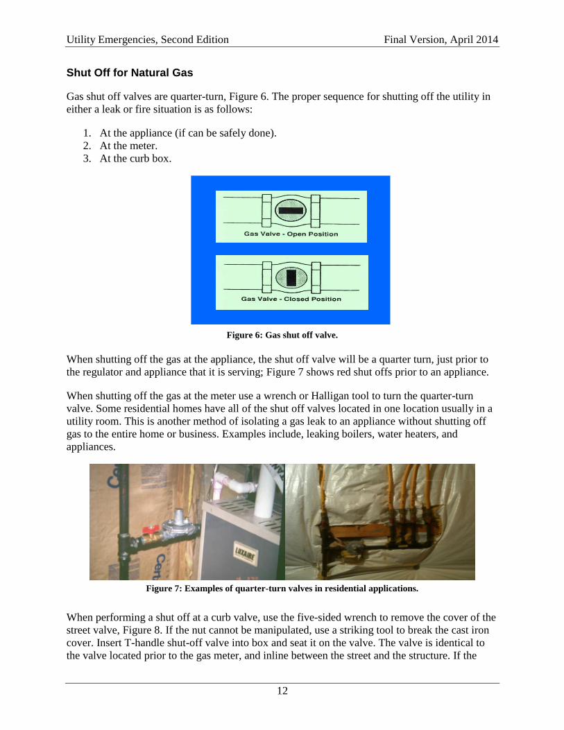
Flexible Gas Line
Flexible gas line has recently been used as alternative to the black iron pipe that was a mainstay
in the construction industry for supplying of gas to a structure. The trade name for flexible gas
line is corrugated stainless steel tubing or CSST /Trac Pipe or Ward Flex. The hose contains a
yellow outer sheath with a thin stainless steel tube that carries the product, Figure 5.The flexible
gas line weighs much less and installation time is often times much faster due to the decreased
weight and material usage.
Historically, the residential gas lines were found at the entry point of the structure to the kitchen
and laundry areas when the initial construction was conducted. Due to increased usage of
flexible gas lines, it is much more popular and common to run appliances in parts of structures
that would not previously been used. For example, this hose can be run through walls to supply a
fireplace in a remote living space such as a finished basement or bedroom. Problems that
frequently occur are damage to the flexible gas line due to punctures in the line from other
utilities or wall hangings. Additional problems exist when construction or home improvements
are done and the flexible gas lines are installed improperly (such as installing a replacement hot
water tank) resulting in leaks at the fittings. Gas leaks can be detected around light switches and
electrical outlets from a damaged line in void spaces and gas seeking the path of least resistance.
Figure 5: Gas main where flexible hose has been used.
Utility Emergencies, Second Edition Final Version, April 2014
12
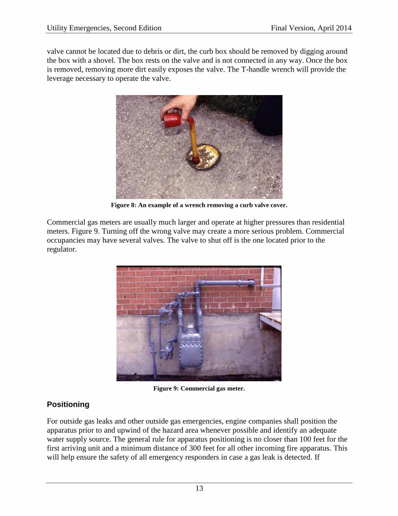
Shut Off for Natural Gas
Gas shut off valves are quarter-turn, Figure 6. The proper sequence for shutting off the utility in
either a leak or fire situation is as follows:
1. At the appliance (if can be safely done).
2. At the meter.
3. At the curb box.
Figure 6: Gas shut off valve.
When shutting off the gas at the appliance, the shut off valve will be a quarter turn, just prior to
the regulator and appliance that it is serving; Figure 7 shows red shut offs prior to an appliance.
When shutting off the gas at the meter use a wrench or Halligan tool to turn the quarter-turn
valve. Some residential homes have all of the shut off valves located in one location usually in a
utility room. This is another method of isolating a gas leak to an appliance without shutting off
gas to the entire home or business. Examples include, leaking boilers, water heaters, and
appliances.
Figure 7: Examples of quarter-turn valves in residential applications.
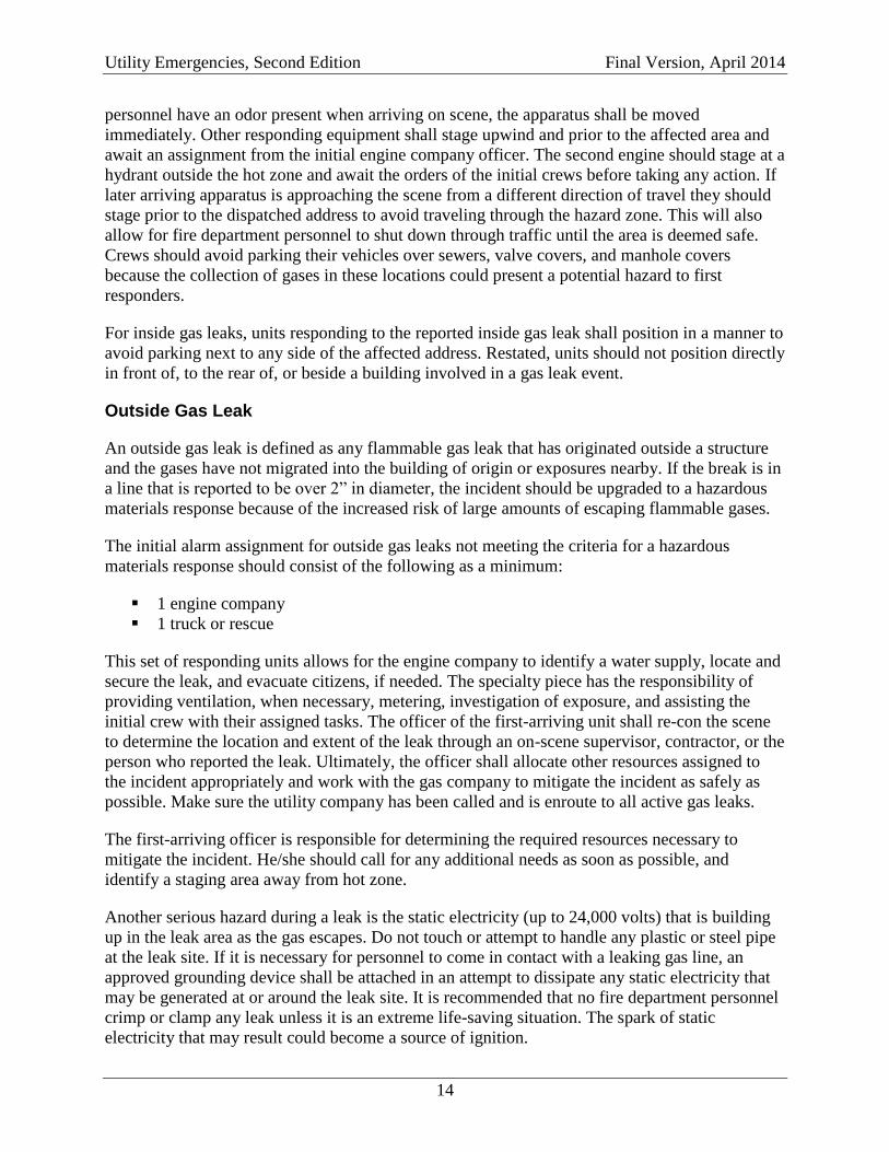
When performing a shut off at a curb valve, use the five-sided wrench to remove the cover of the
street valve, Figure 8. If the nut cannot be manipulated, use a striking tool to break the cast iron
cover. Insert T-handle shut-off valve into box and seat it on the valve. The valve is identical to
the valve located prior to the gas meter, and inline between the street and the structure. If the
Utility Emergencies, Second Edition Final Version, April 2014
13
valve cannot be located due to debris or dirt, the curb box should be removed by digging around
the box with a shovel. The box rests on the valve and is not connected in any way. Once the box
is removed, removing more dirt easily exposes the valve. The T-handle wrench will provide the
leverage necessary to operate the valve.
Figure 8: An example of a wrench removing a curb valve cover.
Commercial gas meters are usually much larger and operate at higher pressures than residential
meters. Figure 9. Turning off the wrong valve may create a more serious problem. Commercial
occupancies may have several valves. The valve to shut off is the one located prior to the
regulator.
Figure 9: Commercial gas meter.
Positioning
For outside gas leaks and other outside gas emergencies, engine companies shall position the
apparatus prior to and upwind of the hazard area whenever possible and identify an adequate
water supply source. The general rule for apparatus positioning is no closer than 100 feet for the
first arriving unit and a minimum distance of 300 feet for all other incoming fire apparatus. This
will help ensure the safety of all emergency responders in case a gas leak is detected. If
Utility Emergencies, Second Edition Final Version, April 2014
14
personnel have an odor present when arriving on scene, the apparatus shall be moved
immediately. Other responding equipment shall stage upwind and prior to the affected area and
await an assignment from the initial engine company officer. The second engine should stage at a
hydrant outside the hot zone and await the orders of the initial crews before taking any action. If
later arriving apparatus is approaching the scene from a different direction of travel they should
stage prior to the dispatched address to avoid traveling through the hazard zone. This will also
allow for fire department personnel to shut down through traffic until the area is deemed safe.
Crews should avoid parking their vehicles over sewers, valve covers, and manhole covers
because the collection of gases in these locations could present a potential hazard to first
responders.
For inside gas leaks, units responding to the reported inside gas leak shall position in a manner to
avoid parking next to any side of the affected address. Restated, units should not position directly
in front of, to the rear of, or beside a building involved in a gas leak event.
Outside Gas Leak
An outside gas leak is defined as any flammable gas leak that has originated outside a structure
and the gases have not migrated into the building of origin or exposures nearby. If the break is in
a line that is reported to be over 2” in diameter, the incident should be upgraded to a hazardous
materials response because of the increased risk of large amounts of escaping flammable gases.
The initial alarm assignment for outside gas leaks not meeting the criteria for a hazardous
materials response should consist of the following as a minimum:
1 engine company
1 truck or rescue
This set of responding units allows for the engine company to identify a water supply, locate and
secure the leak, and evacuate citizens, if needed. The specialty piece has the responsibility of
providing ventilation, when necessary, metering, investigation of exposure, and assisting the
initial crew with their assigned tasks. The officer of the first-arriving unit shall re-con the scene
to determine the location and extent of the leak through an on-scene supervisor, contractor, or the
person who reported the leak. Ultimately, the officer shall allocate other resources assigned to
the incident appropriately and work with the gas company to mitigate the incident as safely as
possible. Make sure the utility company has been called and is enroute to all active gas leaks.
The first-arriving officer is responsible for determining the required resources necessary to
mitigate the incident. He/she should call for any additional needs as soon as possible, and
identify a staging area away from hot zone.
Another serious hazard during a leak is the static electricity (up to 24,000 volts) that is building
up in the leak area as the gas escapes. Do not touch or attempt to handle any plastic or steel pipe
at the leak site. If it is necessary for personnel to come in contact with a leaking gas line, an
approved grounding device shall be attached in an attempt to dissipate any static electricity that
may be generated at or around the leak site. It is recommended that no fire department personnel
crimp or clamp any leak unless it is an extreme life-saving situation. The spark of static
electricity that may result could become a source of ignition.
Utility Emergencies, Second Edition Final Version, April 2014
15
In most cases if the leak is prior to a shut off:
No gas is entering any structure and is dissipating into the atmosphere.
The best course of action is no action.
Don’t cover any pipe that is leaking and do check for migration of gas in surrounding
buildings, basements, and sewers.
Set up a hot zone, wait for the utility company to arrive, and let them mitigate the leak.
The utility company requires their personnel to follow safety rules. Any utility company
personnel in the hot zone shall wear their protective equipment that includes coveralls, hardhat,
Nomex hood and eye protection. Additionally, fire department personnel shall ensure no persons
enter a trench deeper than 5’ that is not shored (29 CFR 1926.651).
To protect the utility company workers, units should position upwind with a 20 lb. dry chemical
extinguisher and a charged hose line when necessary. When protecting the utility company you
should position personnel close to the leak, but out of the immediate hazard area if the gas
ignites. Also take into consideration that hose placement should not hamper the utility company
from getting their equipment in place.
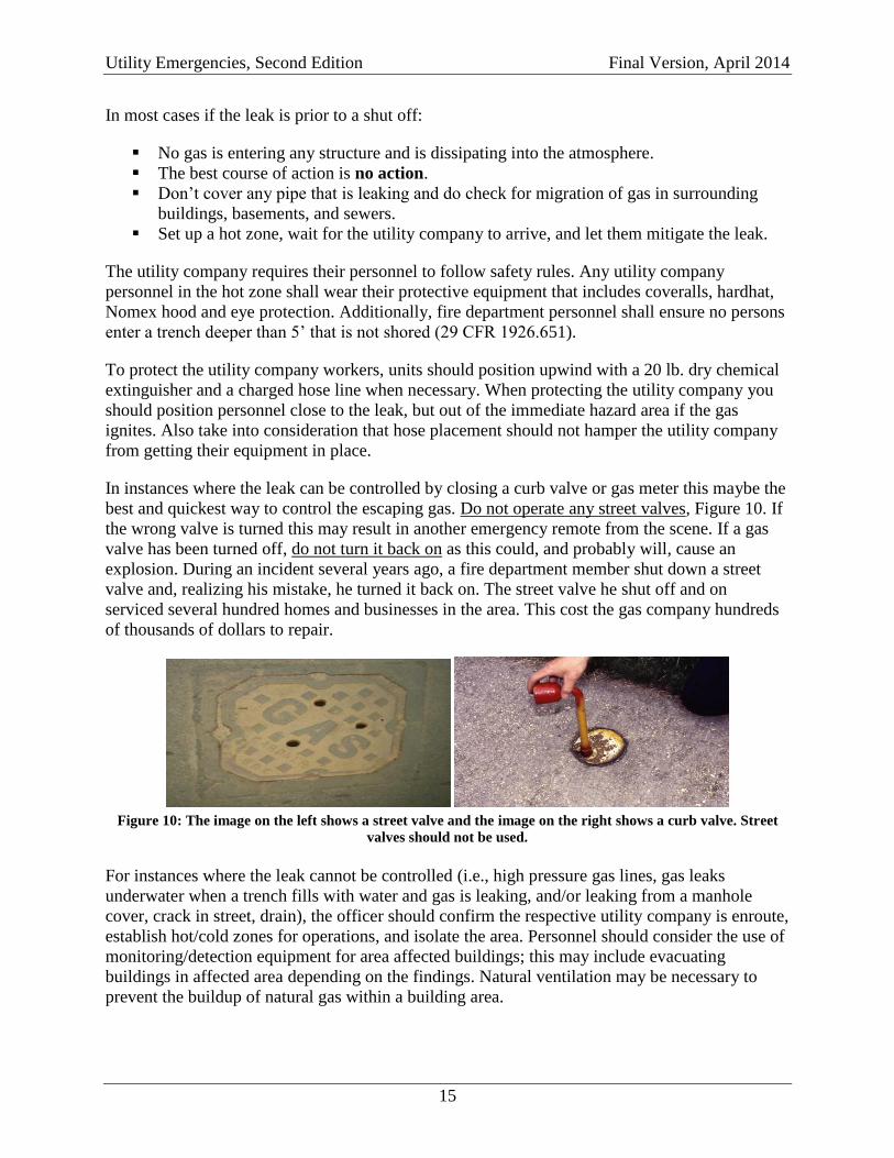
In instances where the leak can be controlled by closing a curb valve or gas meter this maybe the
best and quickest way to control the escaping gas. Do not operate any street valves, Figure 10. If
the wrong valve is turned this may result in another emergency remote from the scene. If a gas
valve has been turned off, do not turn it back on as this could, and probably will, cause an
explosion. During an incident several years ago, a fire department member shut down a street
valve and, realizing his mistake, he turned it back on. The street valve he shut off and on
serviced several hundred homes and businesses in the area. This cost the gas company hundreds
of thousands of dollars to repair.
Figure 10: The image on the left shows a street valve and the image on the right shows a curb valve. Street
valves should not be used.
For instances where the leak cannot be controlled (i.e., high pressure gas lines, gas leaks
underwater when a trench fills with water and gas is leaking, and/or leaking from a manhole
cover, crack in street, drain), the officer should confirm the respective utility company is enroute,
establish hot/cold zones for operations, and isolate the area. Personnel should consider the use of
monitoring/detection equipment for area affected buildings; this may include evacuating
buildings in affected area depending on the findings. Natural ventilation may be necessary to
prevent the buildup of natural gas within a building area.
Utility Emergencies, Second Edition Final Version, April 2014
16
All non-essential personnel, including firefighters and civilians, shall be kept out of the hot zone.
The DOT Emergency Response Guide (ERG) suggests an evacuation distance of 330 feet. This
may include evacuating buildings located within or near the zone. Detection/monitoring
equipment carried on the fire apparatus will be used to monitor these areas.
Combustible gas meters must be intrinsically safe and bump tested prior to entering the hot zone.
Do not depend only on the mercaptan odor to determine if there is a leak. In underground leaks
where natural gas is passed through the soil, the mercaptan odor may be eliminated. The hot zone
will be determined by the OIC using the results of the detection/monitoring equipment. Checking
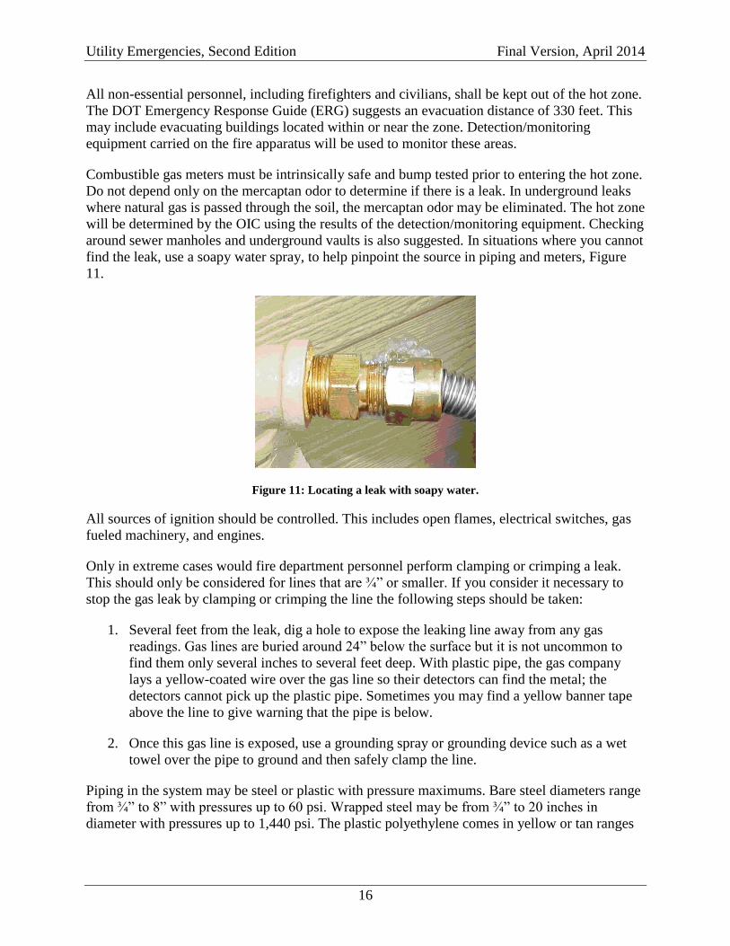
around sewer manholes and underground vaults is also suggested. In situations where you cannot
find the leak, use a soapy water spray, to help pinpoint the source in piping and meters, Figure
11.
Figure 11: Locating a leak with soapy water.
All sources of ignition should be controlled. This includes open flames, electrical switches, gas
fueled machinery, and engines.
Only in extreme cases would fire department personnel perform clamping or crimping a leak.
This should only be considered for lines that are ¾” or smaller. If you consider it necessary to
stop the gas leak by clamping or crimping the line the following steps should be taken:
1. Several feet from the leak, dig a hole to expose the leaking line away from any gas
readings. Gas lines are buried around 24” below the surface but it is not uncommon to
find them only several inches to several feet deep. With plastic pipe, the gas company
lays a yellow-coated wire over the gas line so their detectors can find the metal; the
detectors cannot pick up the plastic pipe. Sometimes you may find a yellow banner tape
above the line to give warning that the pipe is below.
2. Once this gas line is exposed, use a grounding spray or grounding device such as a wet
towel over the pipe to ground and then safely clamp the line.
Piping in the system may be steel or plastic with pressure maximums. Bare steel diameters range
from ¾” to 8” with pressures up to 60 psi. Wrapped steel may be from ¾” to 20 inches in
diameter with pressures up to 1,440 psi. The plastic polyethylene comes in yellow or tan ranges
Utility Emergencies, Second Edition Final Version, April 2014
17
in size from ½” to 8 inches in diameter with pressures up to 80 psi, the polyethylene pipe is
susceptible to static electricity.
The use of hand lines and/or dry chemical extinguishers should take into account the wind
direction, humidity, weight of the gas, and any other factors pertaining to the migration of the
vapor cloud. This information will assist the officer in deciding if a hoseline is to be deployed
and what size the hose line should be as well as where to deploy the extinguisher for use.
Outside Gas Fires
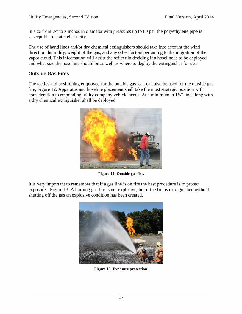
The tactics and positioning employed for the outside gas leak can also be used for the outside gas
fire, Figure 12. Apparatus and hoseline placement shall take the most strategic position with
consideration to responding utility company vehicle needs. At a minimum, a 1¾” line along with
a dry chemical extinguisher shall be deployed.
Figure 12: Outside gas fire.
It is very important to remember that if a gas line is on fire the best procedure is to protect
exposures, Figure 13. A burning gas fire is not explosive, but if the fire is extinguished without
shutting off the gas an explosive condition has been created.
Figure 13: Exposure protection.
Utility Emergencies, Second Edition Final Version, April 2014
18
The fire can extend to other surrounding combustibles and hoselines should be operated to
prevent the spreading of the fire while letting the gas fire continue to burn, Figure 14. Where
possible, keep the area around the leak as dry as possible. This will allow the utility company to
fix the leak rapidly and safely. When the utility company stops the flow of gas the fire will go
out.
Figure 14: Fire involving the gas meter.
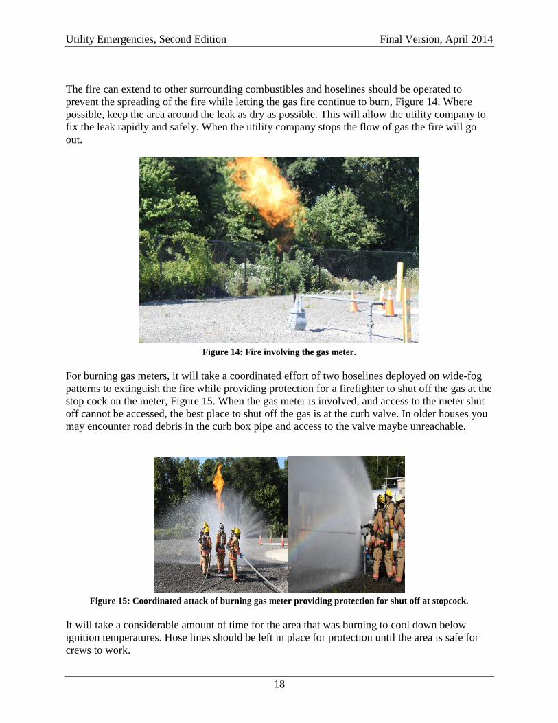
For burning gas meters, it will take a coordinated effort of two hoselines deployed on wide-fog
patterns to extinguish the fire while providing protection for a firefighter to shut off the gas at the
stop cock on the meter, Figure 15. When the gas meter is involved, and access to the meter shut
off cannot be accessed, the best place to shut off the gas is at the curb valve. In older houses you
may encounter road debris in the curb box pipe and access to the valve maybe unreachable.
Figure 15: Coordinated attack of burning gas meter providing protection for shut off at stopcock.
It will take a considerable amount of time for the area that was burning to cool down below
ignition temperatures. Hose lines should be left in place for protection until the area is safe for
crews to work.
Utility Emergencies, Second Edition Final Version, April 2014
19
Inside Gas Leaks
The initial alarm assignment for inside gas should consist of the following as a minimum:
2 engine companies
1 truck or rescue
1 Battalion Chief
If any occupants report feeling ill an EMS unit shall be added.
The tasks that should be completed by the assigned units consist of:
Citizen evacuation, if deemed necessary,
Atmospheric monitoring,
Exposure protection and extinguishment (if necessary),
Hazard mitigation (if it can be accomplished safely), and
Ventilation.
When an IDLH atmosphere is identified, an initial RIT shall be identified and consideration shall
be given to increasing resources for a structure fire response.
Caution and sound judgment should be used when conducting any gas leak investigation. The
primary goal is to protect lives. The officer shall re-con the scene to determine the location and
extent of the leak through an on-scene supervisor, contractor, or person that reported the leak.
The officer shall determine the resource requirements for mitigation and call for any additional
needs as soon as possible and stage resources away from immediate area.
Radios, pagers, cell phones, flashlights and other equipment that is not intrinsically safe should
not be used nor taken into potentially explosive atmospheres. All intrinsically safe equipment
should be turned on prior to entering a gaseous atmosphere.
A hot/cold zone for operations shall be established and all non-essential personnel and civilians
shall be kept out of the hot zone. This may include evacuating an entire building or a group of
buildings in the zone. Where concentrations are the highest, ventilation should be started
immediately. Detection/monitoring equipment carried on the fire apparatus will be used to
monitor these areas; this equipment shall be intrinsically safe and bump tested prior to entering
the hot zone. The hot zone will be determined by detection and monitoring. Closed doors should
be cracked slightly to insert the probe and a reading obtained before opening the door. Opening a
door or venting an atmosphere that is above the Upper Explosive Limit (UEL) could cause an
explosive atmosphere and subsequent explosion.
In large homes, crews should also be cognizant of the possibility that more than one meter could
be serving the single-family dwelling. All occupants shall be evacuated from the danger area. All
ignition sources shall be eliminated by manual controls. No electric switches shall be operated in
the hazard area. Where possible electric service shall be controlled and shut down from the
exterior of the involved structure. Consideration must be given to a potential ignition source
being an auxiliary generator. If the power to a structure is shut off at the electric panel this action
may cause the generator to operate. Secure the generator prior to operating the electric panel.
Utility Emergencies, Second Edition Final Version, April 2014
20
Upper stories, attics and cocklofts need to be monitored due to the vapor density of natural gas
(.55).
All exposures shall be monitored to determine the extent of the leak. All sources of ignition shall
be controlled if necessary. Natural ventilation should be the primary tactic used to remove the
gases. When appropriate, the safest way to remove the hazard would be to shut off the gas at the
meter. However, in large commercial buildings, shutting off the gas at the meter could seriously
disrupt manufacturing procedures and may generate further hazards. Any valve that is turned off
shall be red tagged, notification will made to the utility company, and an available building
representative will be contacted.
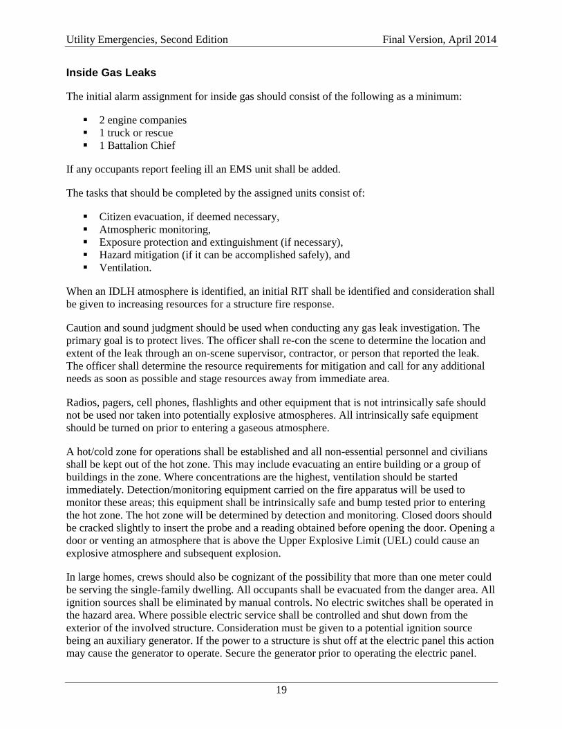
Gas-fired rooftop heating units are widely used in commercial and industrial facilities. Typically
packaged with an air-conditioner and air-handling unit, single-package rooftop units can cover
all the heating, ventilating, and air-conditioning (HVAC) needs of a facility. These self-
contained units can be found on office buildings, grocery stores, schools, and a variety of other
commercial and industrial facilities. Personnel encountering an odor covering an area inside a
facility (with or without inside gas appliances) should assign a resource to check the rooftop for
any odors from the HVAC unit(s) or rooftop service lines, Figure 16.
Figure 16: Rooftop commercial HVAC units and exposed gas lines.
On May 7, 2009, two captains, a lieutenant, and five firefighters were injured during a natural
gas explosion at a strip mall in Maryland. At 1254 hours, dispatch reported a natural gas leak
inside a business at a strip mall. Five minutes later, the initial responding crew and the incident
commander (IC) arrived on scene to find a gas company employee looking for an underground
gas leak. Approximately six minutes later, a natural gas leak was found near the exterior rear
corner of the structure. After 23 minutes on scene, approximately 45 civilians were evacuated
from 7 occupied businesses.
A captain exited the rear door of the business that had reported the natural gas leak and noticed
fire along the roofline. Crews in the front and rear of the structure had begun to pull hose lines as
another captain was looking out the rear doorway of a middle unoccupied business and noticed
the electric meter located on the exterior wall was on fire. Anticipating an explosion, he tried to
leap out the rear doorway. At the same time, a firefighter had entered the front door of the
Utility Emergencies, Second Edition Final Version, April 2014
21
unoccupied business, noticed the heavy smell of natural gas, and felt air rush by as the structure
exploded. Debris and fire blew out the front, rear, and roof of the structure. The captain who
tried to leap out the rear doorway was blown into the rear parking lot and the firefighter who had
entered the front of the structure was blown out the front door and covered with debris.
Numerous other firefighters, primarily near the front of the structure, were blown off their feet
and hit with debris.
NIOSH investigators concluded that, to minimize the risk of similar occurrences, fire
departments should ensure that:
Standard operating guidelines for natural gas leaks are understood and followed;
Utility companies (natural gas and electric) are contacted immediately to cut external
supply/power to structures when gas leaks are suspected;
Gas monitoring equipment is adequately maintained and fire fighters are routinely trained
on proper use;
Ventilation techniques are conducted after ignition sources are mitigated;
Rapid intervention teams are staged at the onset of an incident; and
Collapse/explosion control zones are established when dealing with a potential explosion
hazard.
The key to turning off gas service in any structure is locating the regulator. The regulator takes
street pressure of up to 40 psi and steps it down to somewhere between ½ to ¼ psi prior to the
meter. The piping after the regulator will be larger due to the reduced pressure. In older
occupancies, gas lines found in occupied areas will be no more than ½ psi after the regulator.
In some of the new occupancies, gas lines leaving the main regulator are 2 to 5 psi. This is
because the gas may travel longer distances from the main regulator. Once at the appliance, an
individual regulator will step it down again from 2-5 psi to somewhere between ½ to ¼ psi. Most
commercial and all residential appliances use gas at a pressure of ½ to ¼ psi.
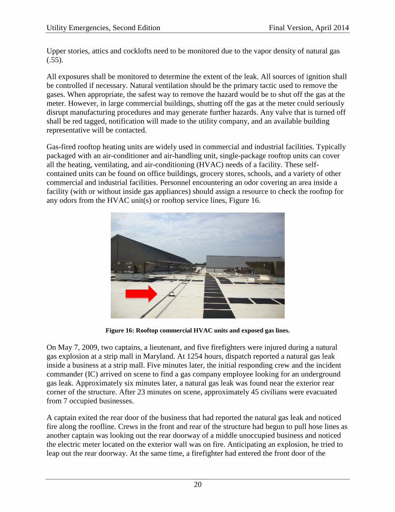
Firefighters should be familiar with residential gas meters. There are two basic types of gas
meters, inside and outside, Figure 17.
Figure 17: Two basic types of gas meters: outside (image on left) and inside (image on right).
Prior knowledge of the area is the best means of determining the presence and type of gas
service. In the absence of prior knowledge, a thorough size-up focusing on meter type will need
Utility Emergencies, Second Edition Final Version, April 2014
22
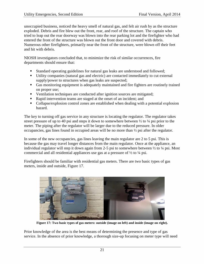
to be undertaken. Examine all areas of the exterior walls near the ground to approximately five
feet above ground. Landscaping may need to be pushed aside to accomplish this. Members are
looking for a meter in outside installations or looking for the vent pipe from the regulator on
inside installations. All inside or enclosed gas installations are required to have the regulator
vented to the outside via piping. This is a safety feature to prevent gas from being discharged to
the interior of the building in the event the regulator fails. The piping vent pipe will be within
five feet of the vent on an inside wall. The vent pipe will likely have a cover screen to keep
water, insects, and debris out of the gas relief piping, Figure 18. If the screen becomes blocked, it
is designed to blow out in relief.
Figure 18: Examples of gas vents; the presence of a gas vent on an exterior wall is an indication of an inside
gas meter.
When turning the gas off at the meter crews should operate the shut-off valve prior to the meter.
The valve is a quarter-turn valve in the piping prior to the regulator. Normally this is the pipe
emanating from the ground. Before closing the valve, note the sound of gas flowing through the
meter and look for movement of the numbers on the face of the meter. After the valve has been
closed, the sound and movement should stop.
Utility Emergencies, Second Edition Final Version, April 2014
23
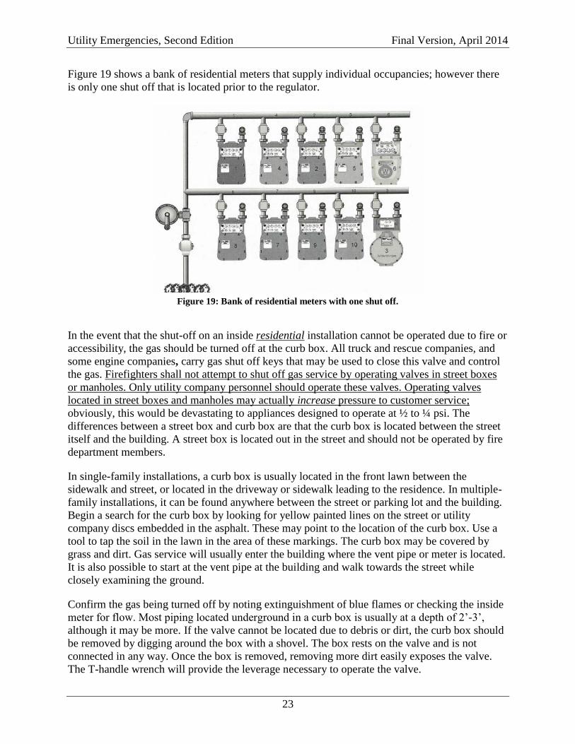
Figure 19 shows a bank of residential meters that supply individual occupancies; however there
is only one shut off that is located prior to the regulator.
Figure 19: Bank of residential meters with one shut off.
In the event that the shut-off on an inside residential installation cannot be operated due to fire or
accessibility, the gas should be turned off at the curb box. All truck and rescue companies, and
some engine companies, carry gas shut off keys that may be used to close this valve and control
the gas. Firefighters shall not attempt to shut off gas service by operating valves in street boxes
or manholes. Only utility company personnel should operate these valves. Operating valves
located in street boxes and manholes may actually increase pressure to customer service;
obviously, this would be devastating to appliances designed to operate at ½ to ¼ psi. The
differences between a street box and curb box are that the curb box is located between the street
itself and the building. A street box is located out in the street and should not be operated by fire
department members.
In single-family installations, a curb box is usually located in the front lawn between the
sidewalk and street, or located in the driveway or sidewalk leading to the residence. In multiple-
family installations, it can be found anywhere between the street or parking lot and the building.
Begin a search for the curb box by looking for yellow painted lines on the street or utility
company discs embedded in the asphalt. These may point to the location of the curb box. Use a
tool to tap the soil in the lawn in the area of these markings. The curb box may be covered by
grass and dirt. Gas service will usually enter the building where the vent pipe or meter is located.
It is also possible to start at the vent pipe at the building and walk towards the street while
closely examining the ground.
Confirm the gas being turned off by noting extinguishment of blue flames or checking the inside
meter for flow. Most piping located underground in a curb box is usually at a depth of 2’-3’,
although it may be more. If the valve cannot be located due to debris or dirt, the curb box should
be removed by digging around the box with a shovel. The box rests on the valve and is not
connected in any way. Once the box is removed, removing more dirt easily exposes the valve.
The T-handle wrench will provide the leverage necessary to operate the valve.
Utility Emergencies, Second Edition Final Version, April 2014
24
In cases where the fire department has been called to an inside gas leak with nothing found, the
source of the odor might be a dry J, P, or S trap in a drain. When a drain has not been used
recently the water in the trap may evaporate and expose the building to sewer gases.
Inside Gas Fires
Initial responders dispatched for a reported structure fire can be surprised when they arrive and
discover a gas meter or a gas appliance has failed is feeding the structure fire. Normal
firefighting operations should commence with the exception of extinguishing the gas fire. A
handline can be used to wet down the surrounding combustibles while the gas is shut off at the
interior meter, if feasible. Gas burning from a meter is far safer than unburned gas accumulating
in a burning basement area quickly reaching an explosive range.
Command must be notified of the situation and request for the gas to be shut down. Shutting off
the gas at the appliance, curb box or the meter should control the gas fire. It is not uncommon for
the fire department to have difficultly shutting off the gas and a request for the gas company
should be called for early into the incident. When the gas meter is involved, and access to the
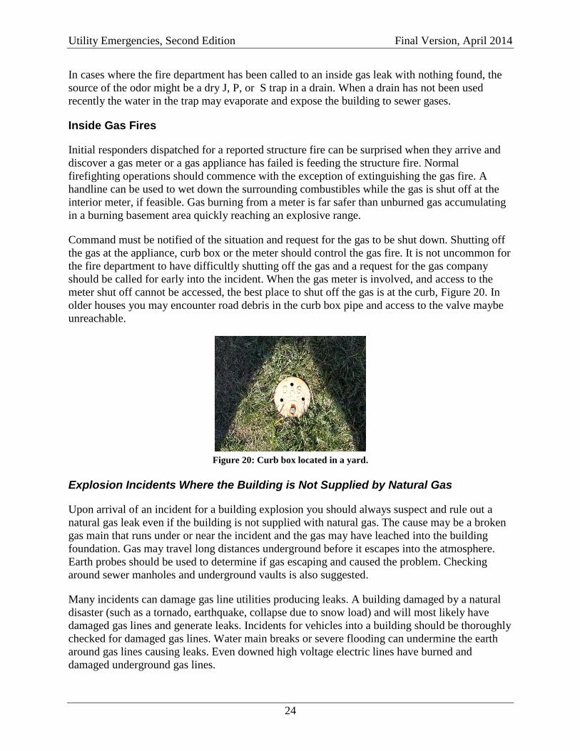
meter shut off cannot be accessed, the best place to shut off the gas is at the curb, Figure 20. In
older houses you may encounter road debris in the curb box pipe and access to the valve maybe
unreachable.
Figure 20: Curb box located in a yard.
Explosion Incidents Where the Building is Not Supplied by Natural Gas
Upon arrival of an incident for a building explosion you should always suspect and rule out a
natural gas leak even if the building is not supplied with natural gas. The cause may be a broken
gas main that runs under or near the incident and the gas may have leached into the building
foundation. Gas may travel long distances underground before it escapes into the atmosphere.
Earth probes should be used to determine if gas escaping and caused the problem. Checking
around sewer manholes and underground vaults is also suggested.
Many incidents can damage gas line utilities producing leaks. A building damaged by a natural
disaster (such as a tornado, earthquake, collapse due to snow load) and will most likely have
damaged gas lines and generate leaks. Incidents for vehicles into a building should be thoroughly
checked for damaged gas lines. Water main breaks or severe flooding can undermine the earth
around gas lines causing leaks. Even downed high voltage electric lines have burned and
damaged underground gas lines.
Utility Emergencies, Second Edition Final Version, April 2014
25
PROPANE
Propane is a fossil fuel that is found mixed with natural gas and petroleum deposits in rocks deep
underground. Propane was formed millions of years ago from dead plants and animals. When the
plants and animals died, they sank to the bottom of the seas where they would mix with sand and
silt that would eventually become thousands of feet thick. Under heat and pressure the composite
would change into petroleum and natural gas deposits.
Propane has an expansion ratio of 270:1. The vapor density of propane is 1.56, making it heavier
than air. Propane will seek low areas and accumulate until it dissipates or find an ignition source.
Propane has a LEL of 2.3 and an UEL of 9.5, and one gallon of liquid weighs 4.23 pounds.
Propane has an ignition temperature between 920° F and 1,120° F.
Propane in its natural form is colorless and odorless and ethyl mercaptan is added to propane for
leak detection. The department of transportation requires any combustible/flammable gas in a
distribution line to be odorized or have a natural odorant. It states that a person with a normal
sense of smell should be able to detect a concentration in air of 20% of the lower explosive limit.
The mercaptan is added at a rate of one pound per 10,000 gallons of liquid propane. This equates
to a one part per billion.
Propane is in a liquid state when contained and stored. In the liquid state propane has a specific
gravity of 0.504 compared to water which is 1.0 making the propane liquid lighter than water.
When released to the atmosphere it will change from a liquid to a vapor; during a release, the
cloud that is visible is not product but the condensed moisture in the air that is cooled by the
leaking product.
Propane Emergencies
Engine companies shall position the apparatus prior to and upwind of the hazard area if at all
possible and determine the most efficient water supply. The other responding units shall stage
upwind and prior to the affected area and await an assignment from the engine company or
Incident Commander.
Outside Propane Leaks
A safe perimeter shall be established using detection/monitoring equipment; these must be
intrinsically safe and shall be bump tested prior to entering the hot zone. Evacuation decisions
should be based on monitoring data, wind direction, terrain, and size of the leak. Checking
around sewer manholes and underground vaults is also suggested. It is imperative to check
surrounding basements of buildings in the area for accumulating gas. Propane gas may travel
long distances underground before it escapes into the atmosphere. Earth probes should be used to
determine if gas escaping and caused the problem.
Propane, being 1½ times heavier than air, will seek low areas, and the use of hoselines may be
required to direct and disperse the vapor cloud away from ignition sources. It is recommended
that two 1¾” hoselines with the nozzles on a narrow fog pattern be deployed for vapor
dispersion. It is also suggested that additional lines be deployed to assist the initial line. When
Utility Emergencies, Second Edition Final Version, April 2014
26
breaking up the vapor cloud avoid allowing the run off to collect at the leak site to keep the area
free of mud.
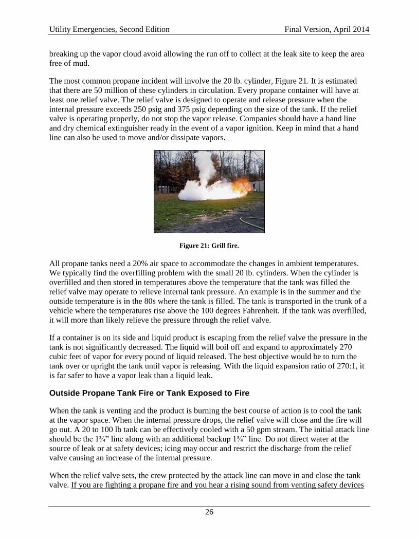
The most common propane incident will involve the 20 lb. cylinder, Figure 21. It is estimated
that there are 50 million of these cylinders in circulation. Every propane container will have at
least one relief valve. The relief valve is designed to operate and release pressure when the
internal pressure exceeds 250 psig and 375 psig depending on the size of the tank. If the relief
valve is operating properly, do not stop the vapor release. Companies should have a hand line
and dry chemical extinguisher ready in the event of a vapor ignition. Keep in mind that a hand
line can also be used to move and/or dissipate vapors.
Figure 21: Grill fire.
All propane tanks need a 20% air space to accommodate the changes in ambient temperatures.
We typically find the overfilling problem with the small 20 lb. cylinders. When the cylinder is
overfilled and then stored in temperatures above the temperature that the tank was filled the
relief valve may operate to relieve internal tank pressure. An example is in the summer and the
outside temperature is in the 80s where the tank is filled. The tank is transported in the trunk of a
vehicle where the temperatures rise above the 100 degrees Fahrenheit. If the tank was overfilled,
it will more than likely relieve the pressure through the relief valve.
If a container is on its side and liquid product is escaping from the relief valve the pressure in the
tank is not significantly decreased. The liquid will boil off and expand to approximately 270
cubic feet of vapor for every pound of liquid released. The best objective would be to turn the
tank over or upright the tank until vapor is releasing. With the liquid expansion ratio of 270:1, it
is far safer to have a vapor leak than a liquid leak.
Outside Propane Tank Fire or Tank Exposed to Fire
When the tank is venting and the product is burning the best course of action is to cool the tank
at the vapor space. When the internal pressure drops, the relief valve will close and the fire will
go out. A 20 to 100 lb tank can be effectively cooled with a 50 gpm stream. The initial attack line
should be the 1¾” line along with an additional backup 1¾” line. Do not direct water at the
source of leak or at safety devices; icing may occur and restrict the discharge from the relief
valve causing an increase of the internal pressure.
When the relief valve sets, the crew protected by the attack line can move in and close the tank
valve. If you are fighting a propane fire and you hear a rising sound from venting safety devices
Utility Emergencies, Second Edition Final Version, April 2014
27
or see discoloration of the tank leave the area immediately. The operation of the tank valve is the
same as a water faucet, left to turn on and right to turn off. When approaching the tank do not
stand or walk in the path of the relief valve; it may open at any time to relieve the tanks internal
pressure. The attack line should continue to cool the tank to prevent re-ignition. If this situation
is at the scene of a structure fire the tanks may be safely removed from the fire area and normal
firefighting operations can continue. A 100-gallon tank can weigh up to 1000 lbs; the best way to
move is to turn the tank on its side and roll it away. Be sure that the valve is completely shut off
and avoid walking near the neck of the tank when rolling. Care should be taken when rolling the
tank down steep grades.
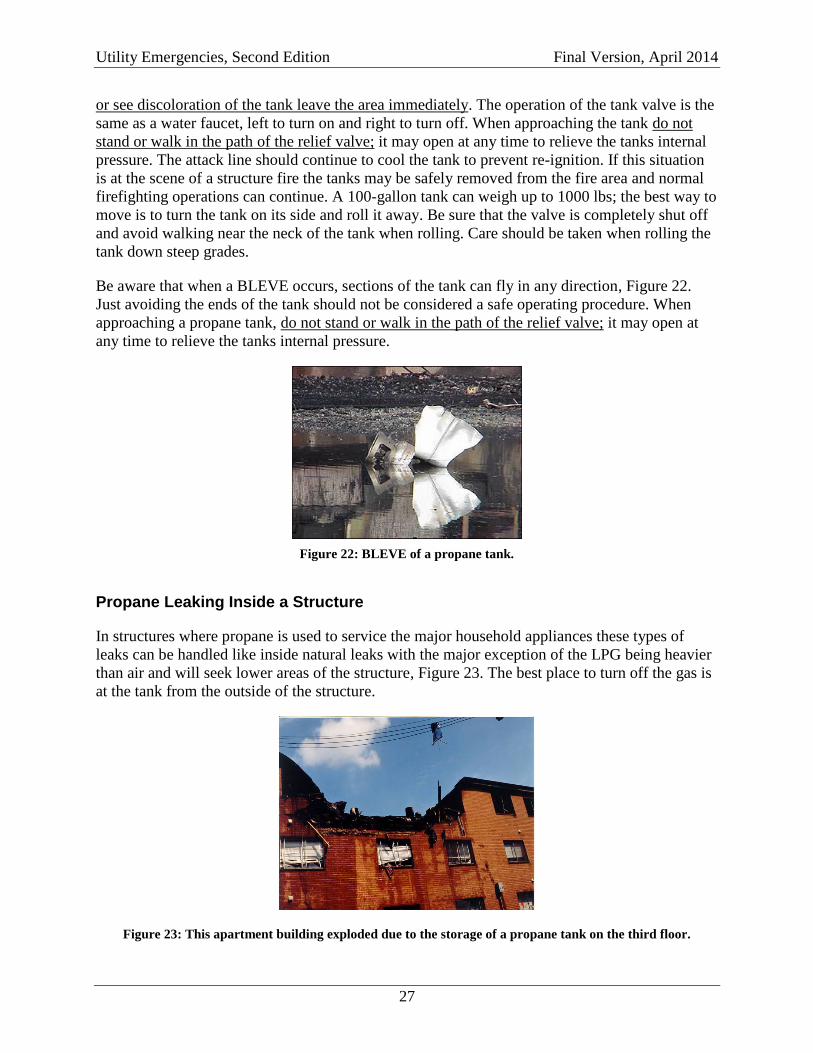
Be aware that when a BLEVE occurs, sections of the tank can fly in any direction, Figure 22.
Just avoiding the ends of the tank should not be considered a safe operating procedure. When
approaching a propane tank, do not stand or walk in the path of the relief valve; it may open at
any time to relieve the tanks internal pressure.
Figure 22: BLEVE of a propane tank.
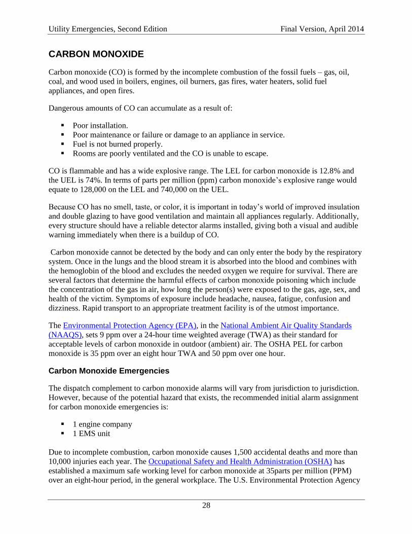
Propane Leaking Inside a Structure
In structures where propane is used to service the major household appliances these types of
leaks can be handled like inside natural leaks with the major exception of the LPG being heavier
than air and will seek lower areas of the structure, Figure 23. The best place to turn off the gas is
at the tank from the outside of the structure.
Figure 23: This apartment building exploded due to the storage of a propane tank on the third floor.
Utility Emergencies, Second Edition Final Version, April 2014
28
CARBON MONOXIDE
Carbon monoxide (CO) is formed by the incomplete combustion of the fossil fuels – gas, oil,
coal, and wood used in boilers, engines, oil burners, gas fires, water heaters, solid fuel
appliances, and open fires.
Dangerous amounts of CO can accumulate as a result of:
Poor installation.
Poor maintenance or failure or damage to an appliance in service.
Fuel is not burned properly.
Rooms are poorly ventilated and the CO is unable to escape.
CO is flammable and has a wide explosive range. The LEL for carbon monoxide is 12.8% and
the UEL is 74%. In terms of parts per million (ppm) carbon monoxide’s explosive range would
equate to 128,000 on the LEL and 740,000 on the UEL.
Because CO has no smell, taste, or color, it is important in today’s world of improved insulation
and double glazing to have good ventilation and maintain all appliances regularly. Additionally,
every structure should have a reliable detector alarms installed, giving both a visual and audible
warning immediately when there is a buildup of CO.
Carbon monoxide cannot be detected by the body and can only enter the body by the respiratory
system. Once in the lungs and the blood stream it is absorbed into the blood and combines with
the hemoglobin of the blood and excludes the needed oxygen we require for survival. There are
several factors that determine the harmful effects of carbon monoxide poisoning which include
the concentration of the gas in air, how long the person(s) were exposed to the gas, age, sex, and
health of the victim. Symptoms of exposure include headache, nausea, fatigue, confusion and
dizziness. Rapid transport to an appropriate treatment facility is of the utmost importance.
The Environmental Protection Agency (EPA), in the National Ambient Air Quality Standards
(NAAQS), sets 9 ppm over a 24-hour time weighted average (TWA) as their standard for
acceptable levels of carbon monoxide in outdoor (ambient) air. The OSHA PEL for carbon
monoxide is 35 ppm over an eight hour TWA and 50 ppm over one hour.
Carbon Monoxide Emergencies
The dispatch complement to carbon monoxide alarms will vary from jurisdiction to jurisdiction.
However, because of the potential hazard that exists, the recommended initial alarm assignment
for carbon monoxide emergencies is:
1 engine company
1 EMS unit
Due to incomplete combustion, carbon monoxide causes 1,500 accidental deaths and more than
10,000 injuries each year. The Occupational Safety and Health Administration (OSHA) has
established a maximum safe working level for carbon monoxide at 35parts per million (PPM)
over an eight-hour period, in the general workplace. The U.S. Environmental Protection Agency
Utility Emergencies, Second Edition Final Version, April 2014
29
has established that residential levels are not to exceed 9 PPM over an eight-hour average.
Commercial buildings have many sources of CO not found in residences such as parking
garages, drive-through windows, auto repair bays, various processes, un-vented gas burners in
large confined spaces, forklifts, etc. Recognizing this, NIOSH established 35 PPM as the
acceptable level for commercial buildings.
Carbon monoxide is an odorless, tasteless, colorless gas that is deadly. It is a by-product of a fuel
burning process. Many appliances such as furnaces, kitchen stoves, hot water heaters, and
automobiles produce carbon monoxide. When a faulty device or unusual conditions exist, carbon
monoxide may be vented into areas where people are present
The majority of carbon monoxide incidents occur in the winter months, and the most common
source of residential CO-related poisoning is un-vented supplemental heaters. Other common
sources of carbon monoxide include:
Malfunctioning cooking appliances.
Tobacco smoke.
Clogged chimney.
Auto exhaust.
Malfunctioning water heater.
Malfunctioning oil, wood, gas, or coal furnaces.
Malfunctioning gas clothes dryer.
Wood burning fireplace, decorative fireplace, gas log burner, or any unvented space
heater.
Appliances in cabins or campers, barbecue grills, lack of adequate ventilation, pool/spa
heaters, and ceiling-mounted heating units.
Generators.
Malfunctioning batteries.
Relining of sewer lines.
Carbon monoxide poisoning may be difficult to diagnose. Its symptoms are similar to the flu,
which may include headache, nausea, fatigue, and dizzy spells. Persons with existing health
problems, such as heart and lung disease, are especially vulnerable, as are infants, children,
pregnant women, and the elderly.
CO detection/monitoring equipment must be intrinsically safe and bump tested prior to entering
the hot zone. Firefighters called to the scene of any CO alarm or smell of natural gas should
dismount from the apparatus with full turnout gear and air packs in place. If the
detection/monitoring equipment shows a reading of 35 ppm or above, the occupancy shall be
immediately evacuated and crews should retreat from the structure and don their SCBA face
piece before making reentry. During the investigative stage, the occupancy should not be
ventilated, ignition sources should be eliminated, and the source of the CO located. Sometimes it
may take many hours for the CO level to rise to the alarm stage and if the occupancy is vented
then the source may not be found.
It is not uncommon to have CO levels up to 10 ppm in a structure. In instances when your
investigation finds readings greater than 10 ppm, you should notify the occupants of the above
Utility Emergencies, Second Edition Final Version, April 2014
30
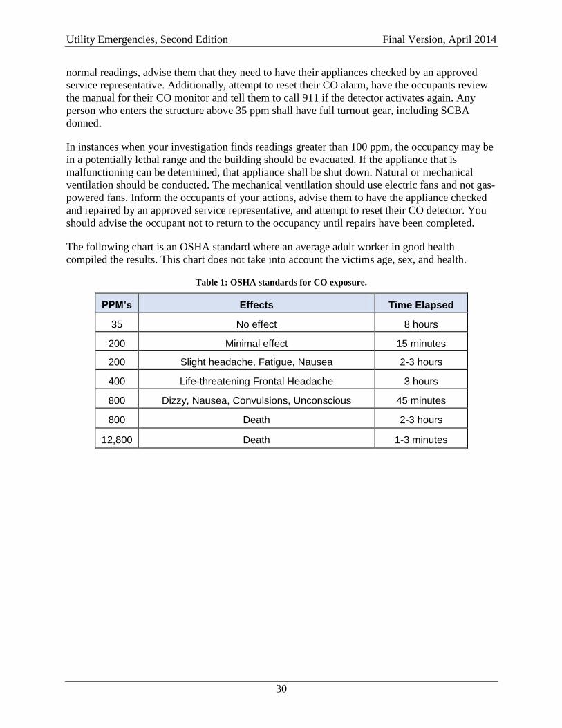
normal readings, advise them that they need to have their appliances checked by an approved
service representative. Additionally, attempt to reset their CO alarm, have the occupants review
the manual for their CO monitor and tell them to call 911 if the detector activates again. Any
person who enters the structure above 35 ppm shall have full turnout gear, including SCBA
donned.
In instances when your investigation finds readings greater than 100 ppm, the occupancy may be
in a potentially lethal range and the building should be evacuated. If the appliance that is
malfunctioning can be determined, that appliance shall be shut down. Natural or mechanical
ventilation should be conducted. The mechanical ventilation should use electric fans and not gas-
powered fans. Inform the occupants of your actions, advise them to have the appliance checked
and repaired by an approved service representative, and attempt to reset their CO detector. You
should advise the occupant not to return to the occupancy until repairs have been completed.
The following chart is an OSHA standard where an average adult worker in good health
compiled the results. This chart does not take into account the victims age, sex, and health.
Table 1: OSHA standards for CO exposure.
PPM’s Effects Time Elapsed
35 No effect 8 hours
200 Minimal effect 15 minutes
200 Slight headache, Fatigue, Nausea 2-3 hours
400 Life-threatening Frontal Headache 3 hours
800 Dizzy, Nausea, Convulsions, Unconscious 45 minutes
800 Death 2-3 hours
12,800 Death 1-3 minutes
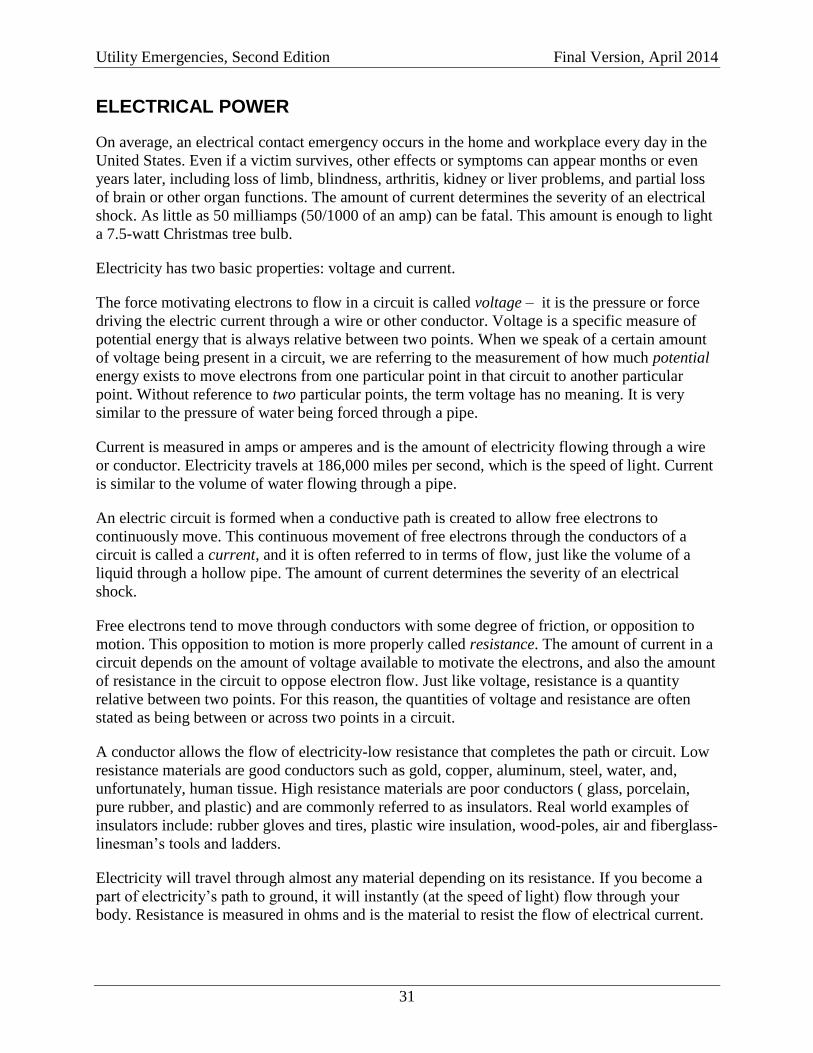
Utility Emergencies, Second Edition Final Version, April 2014
31
ELECTRICAL POWER
On average, an electrical contact emergency occurs in the home and workplace every day in the
United States. Even if a victim survives, other effects or symptoms can appear months or even
years later, including loss of limb, blindness, arthritis, kidney or liver problems, and partial loss
of brain or other organ functions. The amount of current determines the severity of an electrical
shock. As little as 50 milliamps (50/1000 of an amp) can be fatal. This amount is enough to light
a 7.5-watt Christmas tree bulb.
Electricity has two basic properties: voltage and current.
The force motivating electrons to flow in a circuit is called voltage – it is the pressure or force
driving the electric current through a wire or other conductor. Voltage is a specific measure of
potential energy that is always relative between two points. When we speak of a certain amount
of voltage being present in a circuit, we are referring to the measurement of how much potential
energy exists to move electrons from one particular point in that circuit to another particular
point. Without reference to two particular points, the term voltage has no meaning. It is very
similar to the pressure of water being forced through a pipe.
Current is measured in amps or amperes and is the amount of electricity flowing through a wire
or conductor. Electricity travels at 186,000 miles per second, which is the speed of light. Current
is similar to the volume of water flowing through a pipe.
An electric circuit is formed when a conductive path is created to allow free electrons to
continuously move. This continuous movement of free electrons through the conductors of a
circuit is called a current, and it is often referred to in terms of flow, just like the volume of a
liquid through a hollow pipe. The amount of current determines the severity of an electrical
shock.
Free electrons tend to move through conductors with some degree of friction, or opposition to
motion. This opposition to motion is more properly called resistance. The amount of current in a
circuit depends on the amount of voltage available to motivate the electrons, and also the amount
of resistance in the circuit to oppose electron flow. Just like voltage, resistance is a quantity
relative between two points. For this reason, the quantities of voltage and resistance are often
stated as being between or across two points in a circuit.
A conductor allows the flow of electricity-low resistance that completes the path or circuit. Low
resistance materials are good conductors such as gold, copper, aluminum, steel, water, and,
unfortunately, human tissue. High resistance materials are poor conductors ( glass, porcelain,
pure rubber, and plastic) and are commonly referred to as insulators. Real world examples of
insulators include: rubber gloves and tires, plastic wire insulation, wood-poles, air and fiberglass-
linesman’s tools and ladders.
Electricity will travel through almost any material depending on its resistance. If you become a
part of electricity’s path to ground, it will instantly (at the speed of light) flow through your
body. Resistance is measured in ohms and is the material to resist the flow of electrical current.
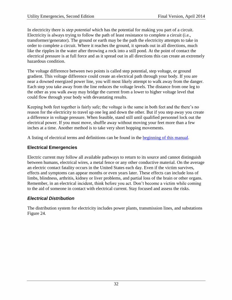
Utility Emergencies, Second Edition Final Version, April 2014
32
In electricity there is step potential which has the potential for making you part of a circuit.
Electricity is always trying to follow the path of least resistance to complete a circuit (i.e.,
transformer/generator). The ground or earth may be the path the electricity attempts to take in
order to complete a circuit. Where it reaches the ground, it spreads out in all directions, much
like the ripples in the water after throwing a rock into a still pond. At the point of contact the
electrical pressure is at full force and as it spread out in all directions this can create an extremely
hazardous condition.
The voltage difference between two points is called step potential, step voltage, or ground
gradient. This voltage difference could create an electrical path through your body. If you are
near a downed energized power line, you will most likely attempt to walk away from the danger.
Each step you take away from the line reduces the voltage levels. The distance from one leg to
the other as you walk away may bridge the current from a lower to higher voltage level that
could flow through your body with devastating results.
Keeping both feet together is fairly safe; the voltage is the same in both feet and the there’s no
reason for the electricity to travel up one leg and down the other. But if you step away you create
a difference in voltage pressure. When feasible, stand still until qualified personnel lock out the
electrical power. If you must move, shuffle away without moving your feet more than a few
inches at a time. Another method is to take very short hopping movements.
A listing of electrical terms and definitions can be found in the beginning of this manual.
Electrical Emergencies
Electric current may follow all available pathways to return to its source and cannot distinguish
between humans, electrical wires, a metal fence or any other conductive material. On the average
an electric contact fatality occurs in the United States each day. Even if the victim survives,
effects and symptoms can appear months or even years later. These effects can include loss of
limbs, blindness, arthritis, kidney or liver problems, and partial loss of the brain or other organs.
Remember, in an electrical incident, think before you act. Don’t become a victim while coming
to the aid of someone in contact with electrical current. Stay focused and assess the risks.
Electrical Distribution
The distribution system for electricity includes power plants, transmission lines, and substations
Figure 24.
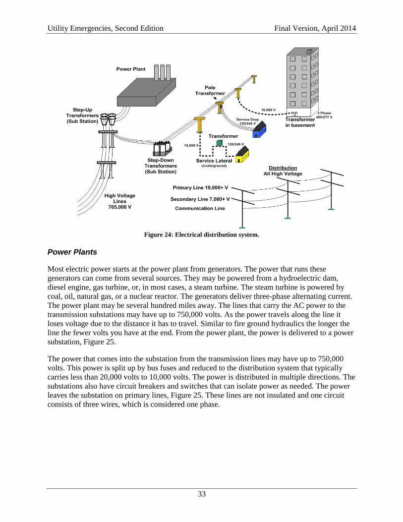
Utility Emergencies, Second Edition Final Version, April 2014
33
Figure 24: Electrical distribution system.
Power Plants
Most electric power starts at the power plant from generators. The power that runs these
generators can come from several sources. They may be powered from a hydroelectric dam,
diesel engine, gas turbine, or, in most cases, a steam turbine. The steam turbine is powered by
coal, oil, natural gas, or a nuclear reactor. The generators deliver three-phase alternating current.
The power plant may be several hundred miles away. The lines that carry the AC power to the
transmission substations may have up to 750,000 volts. As the power travels along the line it
loses voltage due to the distance it has to travel. Similar to fire ground hydraulics the longer the
line the fewer volts you have at the end. From the power plant, the power is delivered to a power
substation, Figure 25.
The power that comes into the substation from the transmission lines may have up to 750,000
volts. This power is split up by bus fuses and reduced to the distribution system that typically
carries less than 20,000 volts to 10,000 volts. The power is distributed in multiple directions. The
substations also have circuit breakers and switches that can isolate power as needed. The power
leaves the substation on primary lines, Figure 25. These lines are not insulated and one circuit
consists of three wires, which is considered one phase.
Utility Emergencies, Second Edition Final Version, April 2014
34
Figure 25: An electrical substation (left) and primary lines (right).
The power is reduced again in transformers located on the top of poles or in ground transformers,
Figure 26. The transformers regulate the voltage in the lines to prevent over voltage and under
voltage conditions. Either the power or the telephone company owns the power poles. On any
power pole you may find phone and/or cable lines.
Figure 26: Examples of pole (left) and ground (right) transformers.
The power is reduced from the primary line to voltage for houses or businesses. One transformer
normally carries up to ten houses. House current is 120/240 volts (single phase). The current in
commercial and some large homes is 240/120 Delta, 208/120Y 3 phase or 480/277 three-phase.
The power lines from the pole to a house or business are called secondary lines. These lines
normally consist of three lines. Two are insulated that carry the power and an un-insulated line,
which is the neutral. In some cases the neutral line may be insulated. Newer areas have the
power lines below the ground. These are called UG conductors and may be directly buried in the
ground or may be enclosed in conduit. The primary lines are supposed to be buried 30” to 36”
below grade. The secondary lines are to be 24” below grade. Do not trust these minimum depth
requirements as it can be shallower due to final grading of property. Although they are not
always correct, Miss Utility should be called to mark any excavation site.
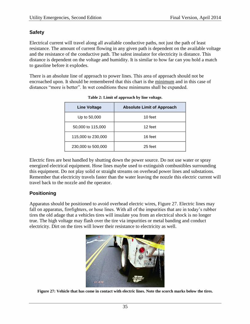
Utility Emergencies, Second Edition Final Version, April 2014
35
Safety
Electrical current will travel along all available conductive paths, not just the path of least
resistance. The amount of current flowing in any given path is dependent on the available voltage
and the resistance of the conductive path. The safest insulator for electricity is distance. This
distance is dependent on the voltage and humidity. It is similar to how far can you hold a match
to gasoline before it explodes.
There is an absolute line of approach to power lines. This area of approach should not be
encroached upon. It should be remembered that this chart is the minimum and in this case of
distances “more is better”. In wet conditions these minimums shall be expanded.
Table 2: Limit of approach by line voltage.
Line Voltage Absolute Limit of Approach
Up to 50,000 10 feet
50,000 to 115,000 12 feet
115,000 to 230,000 16 feet
230,000 to 500,000 25 feet
Electric fires are best handled by shutting down the power source. Do not use water or spray
energized electrical equipment. Hose lines maybe used to extinguish combustibles surrounding
this equipment. Do not play solid or straight streams on overhead power lines and substations.
Remember that electricity travels faster than the water leaving the nozzle this electric current will
travel back to the nozzle and the operator.
Positioning
Apparatus should be positioned to avoid overhead electric wires, Figure 27. Electric lines may
fall on apparatus, firefighters, or hose lines. With all of the impurities that are in today’s rubber
tires the old adage that a vehicles tires will insulate you from an electrical shock is no longer
true. The high voltage may flash over the tire via impurities or metal banding and conduct
electricity. Dirt on the tires will lower their resistance to electricity as well.
Figure 27: Vehicle that has come in contact with electric lines. Note the scorch marks below the tires.
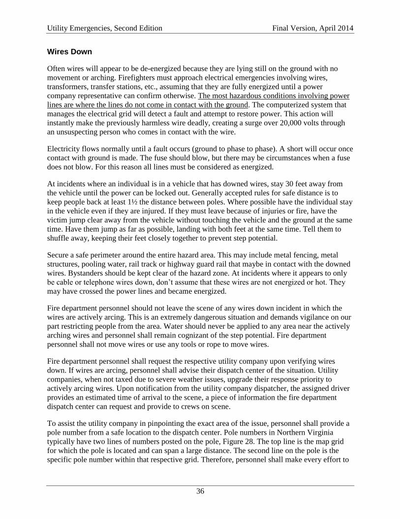
Utility Emergencies, Second Edition Final Version, April 2014
36
Wires Down
Often wires will appear to be de-energized because they are lying still on the ground with no
movement or arching. Firefighters must approach electrical emergencies involving wires,
transformers, transfer stations, etc., assuming that they are fully energized until a power
company representative can confirm otherwise. The most hazardous conditions involving power
lines are where the lines do not come in contact with the ground. The computerized system that
manages the electrical grid will detect a fault and attempt to restore power. This action will
instantly make the previously harmless wire deadly, creating a surge over 20,000 volts through
an unsuspecting person who comes in contact with the wire.
Electricity flows normally until a fault occurs (ground to phase to phase). A short will occur once
contact with ground is made. The fuse should blow, but there may be circumstances when a fuse
does not blow. For this reason all lines must be considered as energized.
At incidents where an individual is in a vehicle that has downed wires, stay 30 feet away from
the vehicle until the power can be locked out. Generally accepted rules for safe distance is to
keep people back at least 1½ the distance between poles. Where possible have the individual stay
in the vehicle even if they are injured. If they must leave because of injuries or fire, have the
victim jump clear away from the vehicle without touching the vehicle and the ground at the same
time. Have them jump as far as possible, landing with both feet at the same time. Tell them to
shuffle away, keeping their feet closely together to prevent step potential.
Secure a safe perimeter around the entire hazard area. This may include metal fencing, metal
structures, pooling water, rail track or highway guard rail that maybe in contact with the downed
wires. Bystanders should be kept clear of the hazard zone. At incidents where it appears to only
be cable or telephone wires down, don’t assume that these wires are not energized or hot. They
may have crossed the power lines and became energized.
Fire department personnel should not leave the scene of any wires down incident in which the
wires are actively arcing. This is an extremely dangerous situation and demands vigilance on our
part restricting people from the area. Water should never be applied to any area near the actively
arching wires and personnel shall remain cognizant of the step potential. Fire department
personnel shall not move wires or use any tools or rope to move wires.
Fire department personnel shall request the respective utility company upon verifying wires
down. If wires are arcing, personnel shall advise their dispatch center of the situation. Utility
companies, when not taxed due to severe weather issues, upgrade their response priority to
actively arcing wires. Upon notification from the utility company dispatcher, the assigned driver
provides an estimated time of arrival to the scene, a piece of information the fire department
dispatch center can request and provide to crews on scene.
To assist the utility company in pinpointing the exact area of the issue, personnel shall provide a
pole number from a safe location to the dispatch center. Pole numbers in Northern Virginia
typically have two lines of numbers posted on the pole, Figure 28. The top line is the map grid
for which the pole is located and can span a large distance. The second line on the pole is the
specific pole number within that respective grid. Therefore, personnel shall make every effort to
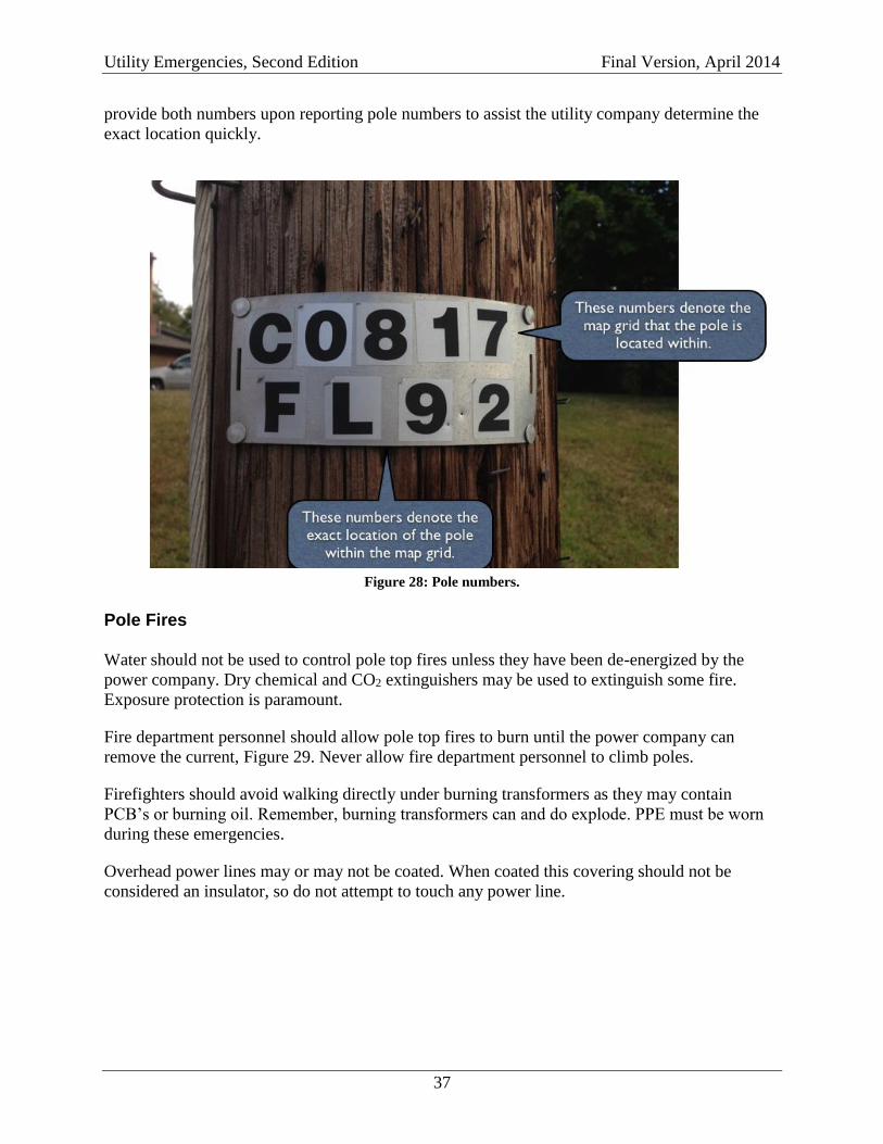
Utility Emergencies, Second Edition Final Version, April 2014
37
provide both numbers upon reporting pole numbers to assist the utility company determine the
exact location quickly.
Figure 28: Pole numbers.
Pole Fires
Water should not be used to control pole top fires unless they have been de-energized by the
power company. Dry chemical and CO2 extinguishers may be used to extinguish some fire.
Exposure protection is paramount.
Fire department personnel should allow pole top fires to burn until the power company can
remove the current, Figure 29. Never allow fire department personnel to climb poles.
Firefighters should avoid walking directly under burning transformers as they may contain
PCB’s or burning oil. Remember, burning transformers can and do explode. PPE must be worn
during these emergencies.
Overhead power lines may or may not be coated. When coated this covering should not be
considered an insulator, so do not attempt to touch any power line.
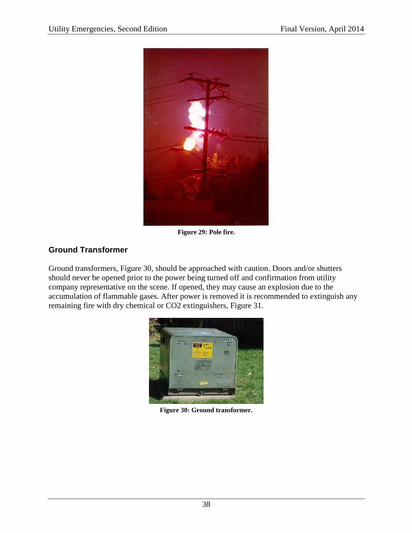
Utility Emergencies, Second Edition Final Version, April 2014
38
Figure 29: Pole fire.
Ground Transformer
Ground transformers, Figure 30, should be approached with caution. Doors and/or shutters
should never be opened prior to the power being turned off and confirmation from utility
company representative on the scene. If opened, they may cause an explosion due to the
accumulation of flammable gases. After power is removed it is recommended to extinguish any
remaining fire with dry chemical or CO2 extinguishers, Figure 31.
Figure 30: Ground transformer.
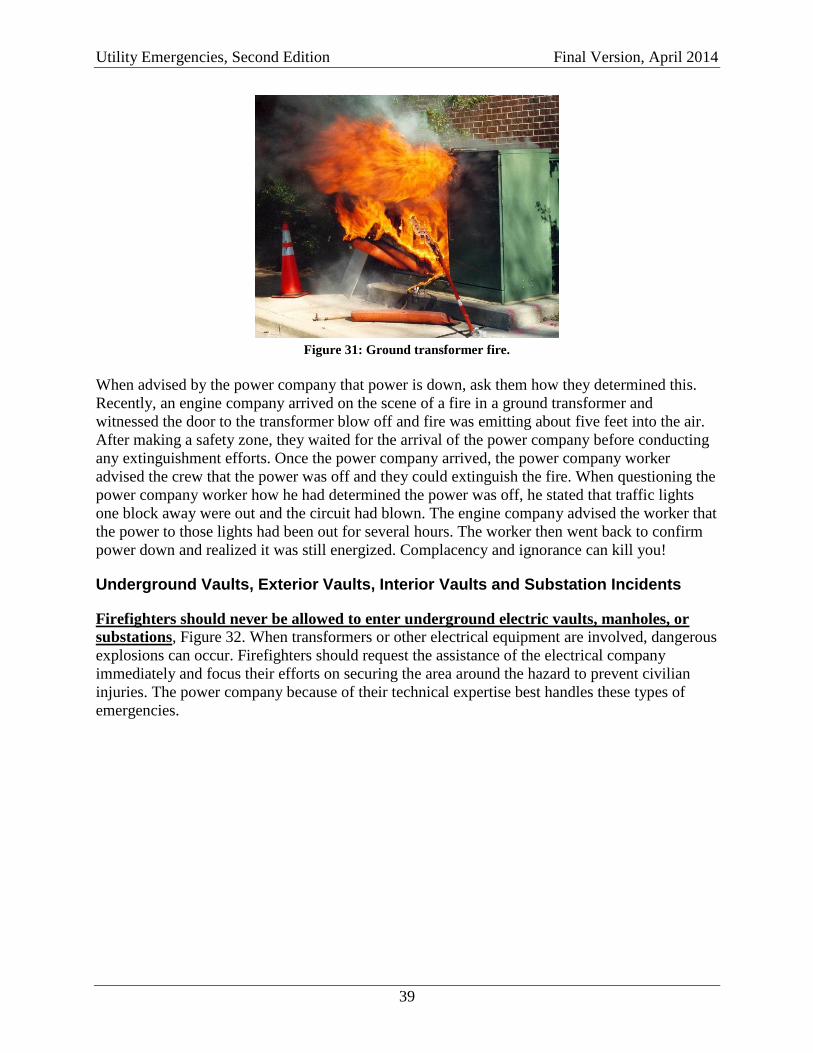
Utility Emergencies, Second Edition Final Version, April 2014
39
Figure 31: Ground transformer fire.
When advised by the power company that power is down, ask them how they determined this.
Recently, an engine company arrived on the scene of a fire in a ground transformer and
witnessed the door to the transformer blow off and fire was emitting about five feet into the air.
After making a safety zone, they waited for the arrival of the power company before conducting
any extinguishment efforts. Once the power company arrived, the power company worker
advised the crew that the power was off and they could extinguish the fire. When questioning the
power company worker how he had determined the power was off, he stated that traffic lights
one block away were out and the circuit had blown. The engine company advised the worker that
the power to those lights had been out for several hours. The worker then went back to confirm
power down and realized it was still energized. Complacency and ignorance can kill you!
Underground Vaults, Exterior Vaults, Interior Vaults and Substation Incidents
Firefighters should never be allowed to enter underground electric vaults, manholes, or
substations, Figure 32. When transformers or other electrical equipment are involved, dangerous
explosions can occur. Firefighters should request the assistance of the electrical company
immediately and focus their efforts on securing the area around the hazard to prevent civilian
injuries. The power company because of their technical expertise best handles these types of
emergencies.
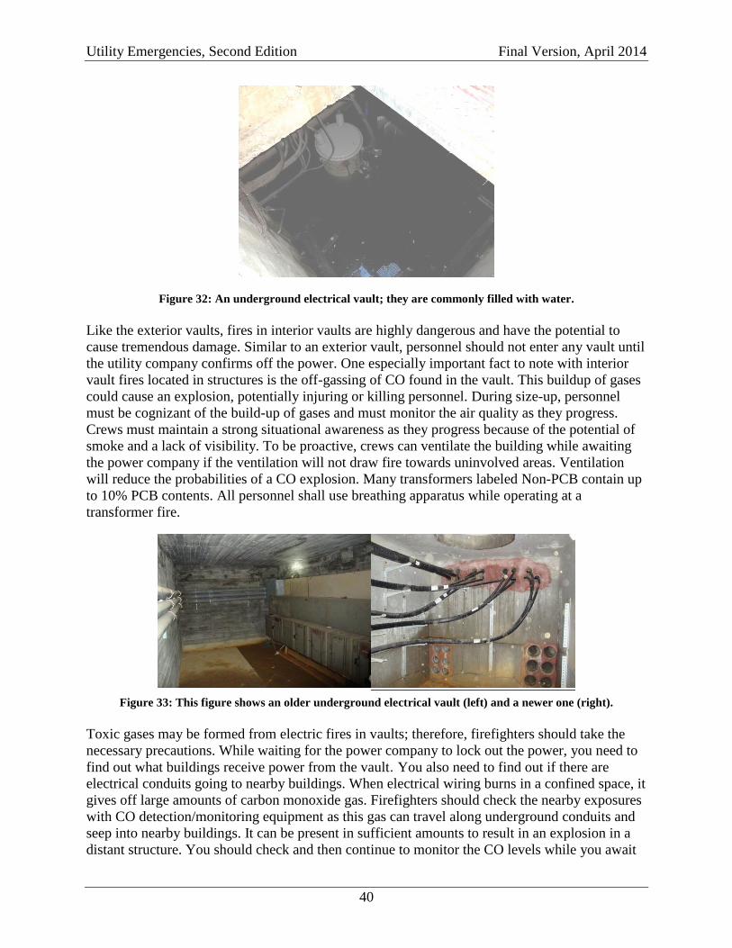
Utility Emergencies, Second Edition Final Version, April 2014
40
Figure 32: An underground electrical vault; they are commonly filled with water.
Like the exterior vaults, fires in interior vaults are highly dangerous and have the potential to
cause tremendous damage. Similar to an exterior vault, personnel should not enter any vault until
the utility company confirms off the power. One especially important fact to note with interior
vault fires located in structures is the off-gassing of CO found in the vault. This buildup of gases
could cause an explosion, potentially injuring or killing personnel. During size-up, personnel
must be cognizant of the build-up of gases and must monitor the air quality as they progress.
Crews must maintain a strong situational awareness as they progress because of the potential of
smoke and a lack of visibility. To be proactive, crews can ventilate the building while awaiting
the power company if the ventilation will not draw fire towards uninvolved areas. Ventilation
will reduce the probabilities of a CO explosion. Many transformers labeled Non-PCB contain up
to 10% PCB contents. All personnel shall use breathing apparatus while operating at a
transformer fire.
Figure 33: This figure shows an older underground electrical vault (left) and a newer one (right).
Toxic gases may be formed from electric fires in vaults; therefore, firefighters should take the
necessary precautions. While waiting for the power company to lock out the power, you need to
find out what buildings receive power from the vault. You also need to find out if there are
electrical conduits going to nearby buildings. When electrical wiring burns in a confined space, it
gives off large amounts of carbon monoxide gas. Firefighters should check the nearby exposures
with CO detection/monitoring equipment as this gas can travel along underground conduits and
seep into nearby buildings. It can be present in sufficient amounts to result in an explosion in a
distant structure. You should check and then continue to monitor the CO levels while you await
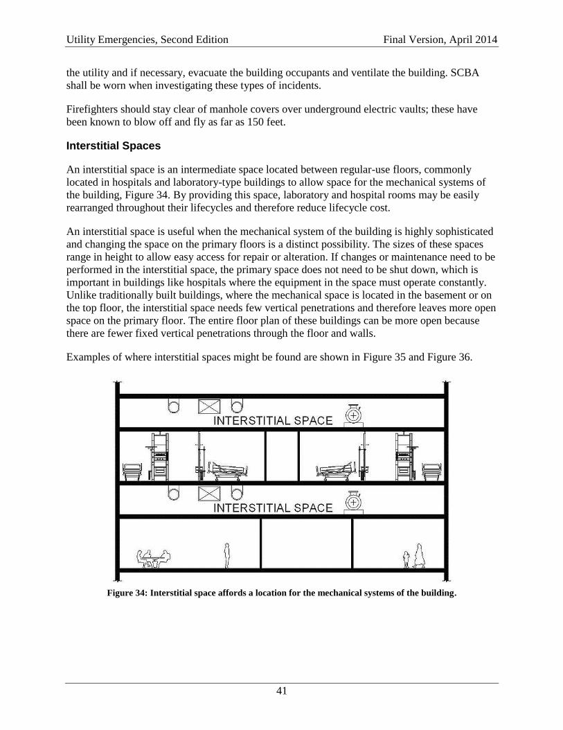
Utility Emergencies, Second Edition Final Version, April 2014
41
the utility and if necessary, evacuate the building occupants and ventilate the building. SCBA
shall be worn when investigating these types of incidents.
Firefighters should stay clear of manhole covers over underground electric vaults; these have
been known to blow off and fly as far as 150 feet.
Interstitial Spaces
An interstitial space is an intermediate space located between regular-use floors, commonly
located in hospitals and laboratory-type buildings to allow space for the mechanical systems of
the building, Figure 34. By providing this space, laboratory and hospital rooms may be easily
rearranged throughout their lifecycles and therefore reduce lifecycle cost.
An interstitial space is useful when the mechanical system of the building is highly sophisticated
and changing the space on the primary floors is a distinct possibility. The sizes of these spaces
range in height to allow easy access for repair or alteration. If changes or maintenance need to be
performed in the interstitial space, the primary space does not need to be shut down, which is
important in buildings like hospitals where the equipment in the space must operate constantly.
Unlike traditionally built buildings, where the mechanical space is located in the basement or on
the top floor, the interstitial space needs few vertical penetrations and therefore leaves more open
space on the primary floor. The entire floor plan of these buildings can be more open because
there are fewer fixed vertical penetrations through the floor and walls.
Examples of where interstitial spaces might be found are shown in Figure 35 and Figure 36.
Figure 34: Interstitial space affords a location for the mechanical systems of the building.
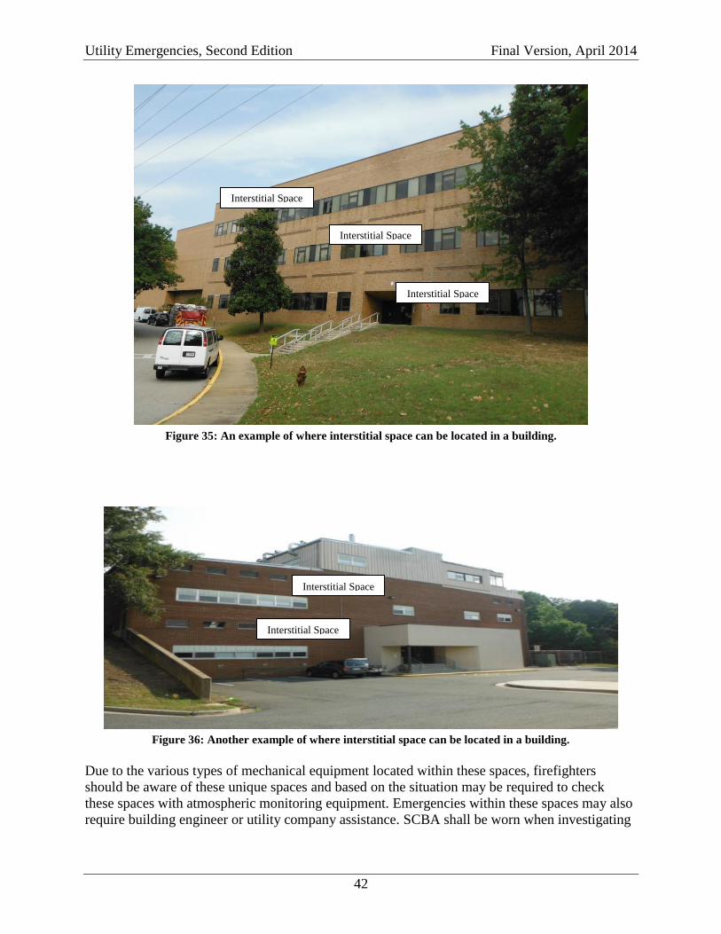
Utility Emergencies, Second Edition Final Version, April 2014
42
Figure 35: An example of where interstitial space can be located in a building.
Figure 36: Another example of where interstitial space can be located in a building.
Due to the various types of mechanical equipment located within these spaces, firefighters
should be aware of these unique spaces and based on the situation may be required to check
these spaces with atmospheric monitoring equipment. Emergencies within these spaces may also
require building engineer or utility company assistance. SCBA shall be worn when investigating
Interstitial Space
Interstitial Space
Interstitial Space
Interstitial Space
Interstitial Space
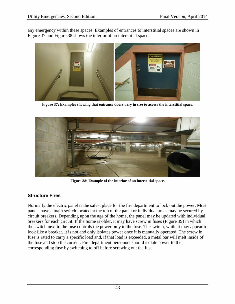
Utility Emergencies, Second Edition Final Version, April 2014
43
any emergency within these spaces. Examples of entrances to interstitial spaces are shown in
Figure 37 and Figure 38 shows the interior of an interstitial space.
Figure 37: Examples showing that entrance doors vary in size to access the interstitial space.
Figure 38: Example of the interior of an interstitial space.
Structure Fires
Normally the electric panel is the safest place for the fire department to lock out the power. Most
panels have a main switch located at the top of the panel or individual areas may be secured by
circuit breakers. Depending upon the age of the home, the panel may be updated with individual
breakers for each circuit. If the home is older, it may have screw in fuses (Figure 39) in which
the switch next to the fuse controls the power only to the fuse. The switch, while it may appear to
look like a breaker, it is not and only isolates power once it is manually operated. The screw in
fuse is rated to carry a specific load and, if that load is exceeded, a metal bar will melt inside of
the fuse and stop the current. Fire department personnel should isolate power to the
corresponding fuse by switching to off before screwing out the fuse.
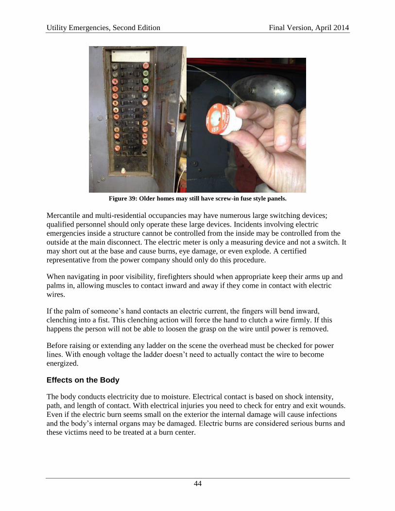
Utility Emergencies, Second Edition Final Version, April 2014
44
Figure 39: Older homes may still have screw-in fuse style panels.
Mercantile and multi-residential occupancies may have numerous large switching devices;
qualified personnel should only operate these large devices. Incidents involving electric
emergencies inside a structure cannot be controlled from the inside may be controlled from the
outside at the main disconnect. The electric meter is only a measuring device and not a switch. It
may short out at the base and cause burns, eye damage, or even explode. A certified
representative from the power company should only do this procedure.
When navigating in poor visibility, firefighters should when appropriate keep their arms up and
palms in, allowing muscles to contact inward and away if they come in contact with electric
wires.
If the palm of someone’s hand contacts an electric current, the fingers will bend inward,
clenching into a fist. This clenching action will force the hand to clutch a wire firmly. If this
happens the person will not be able to loosen the grasp on the wire until power is removed.
Before raising or extending any ladder on the scene the overhead must be checked for power
lines. With enough voltage the ladder doesn’t need to actually contact the wire to become
energized.
Effects on the Body
The body conducts electricity due to moisture. Electrical contact is based on shock intensity,
path, and length of contact. With electrical injuries you need to check for entry and exit wounds.
Even if the electric burn seems small on the exterior the internal damage will cause infections
and the body’s internal organs may be damaged. Electric burns are considered serious burns and
these victims need to be treated at a burn center.
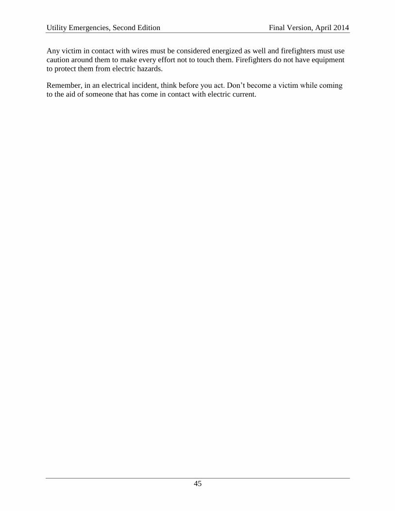
Utility Emergencies, Second Edition Final Version, April 2014
45
Any victim in contact with wires must be considered energized as well and firefighters must use
caution around them to make every effort not to touch them. Firefighters do not have equipment
to protect them from electric hazards.
Remember, in an electrical incident, think before you act. Don’t become a victim while coming
to the aid of someone that has come in contact with electric current.
Utility Emergencies, Second Edition Final Version, April 2014
46
WATER EMERGENCIES
In the event of a water emergency, firefighters may elect to close the main supply valve where it
enters the structure. The main supply valve can typically be found in the basement or utility
room. Water can also be shut off at the street by closing the valve at the meter in the curb box.
Controlling water service in commercial buildings may require closing several valves in different
locations and will require assistance from the building engineer or the water company. The
presence of an armored ground cable attached to a water pipe extending from the electric meter
can assist in identifying the main supply line.
Personnel should evaluate and assess the impact of the water emergency on the electrical system.
Specifically, it water is rising in the basement, personnel should quickly assess the location and
status of the main breaker panel and if outlets are submerged in the rising water.
If no electrical emergency exists, personnel can mitigate the presence of water in the basement
by:
Locating a floor drain (basement sink or shower stall) and removing any debris around
the drain will assist in the removal of water.
Remove the toilet bowl, if present, as this will allow water to drain from the floor area
and out of the structure if this drain is not the source of the flood.
Clearly mark and announce any drain you clear or any toilet you remove to prevent any
persons from getting any part of their body sucked into the drain.
Notifications
When utility control is completed, command shall be notified that the service was shut off and
how or where it was done (e.g., gas shut off at the meter or electric to the apartment shut off at
the main breaker). Any time the fire department shuts off utility service, the utility company
must be notified. They shall be told how or where it was shut off and the reason for shut off.
Utility companies normally respond within a reasonable length of time. If it is not practical to
wait for the utility company to arrive on scene, the unit officer shall fill out a red utility shut off
tag or notification tag and attach it to the affected appliance or lock out.
Should the gas, water, or electric be controlled in a specific area or at the specific appliance, the
officer in charge should provide recommendations to the owner or occupant to seek out a
licensed or certified technician to restore the area or appliance to working order.
If the fire department must also turn off a sprinkler system to a commercial building, proper
notifications to the fire inspection division/department or fire marshal’s office in the jurisdiction
of the affected structure shall be made. The occupancy may need to institute a fire watch until the
system can be restored. For further information regarding fire watch scenarios, contact the
relevant fire inspections division in the authority having jurisdiction or the local fire marshal.