Embed Size (px)
Citation preview

-
-
-
-
-
-
-
""'
-
-
-
-
-
•
-
-
-
PICI(..up 6ELFTESTOK
INSTRUCTION MANUAL The Premier Multifunction
DC Protective Relay
(IJ :13 Utility Relay Company / Chagrin Falls, OH 44023 Phone: 888.289.2864 www. utilityrelay. com
www . El
ectric
alPar
tMan
uals
. com
1 .0
2.0
3.0
4.0
5.0
ZERO-Hertz. DC Trip Unit- Instruction Manual www.utilitvrelay.com
Table Of Contents
Introduction Page
Features 2. 1 DC Current Sensing 2.2 UV Overload trip 2.3 Ground Fault 4 2.4 16 Character Display 2.5 Last Trip Data 2.6 Current Transducers 2.7 Breaker Tripping 2.8 Alarm Relay 2.9 Battery
Options 3. 1 External Connections 3.2 Optional Connections 3.3 Communications Option 3.4 Shunt Input Option
Security Key
Commissioning 5. 1 Power-Up the Trip Unit 9 5.2 Security Key During Commissioning 5.3 Transducer I Shunt Input Select 5.4 Transducer I Shunt Rating 5.5 Long-Time Pick-Up Setting 5.6 Long-Time Delay Setting
5.6. 1 L T Thermal Memory 5.7 Short-Time Pick-Up Setting 5.8 Short-Time Delay Setting 5.9 Short-Time 121" 5. 1 0 Instantaneous Pick-Up Setting 5. 1 1 Ground Fault Pick-Up Setting
5. 1 1 . 1 Ground Fault % Restraint 5. 1 2 Ground Fault Delay Setting 5. 1 3 Ground Fault 12T 5. 14 Reverse Current Pick-Up 6. 1 5 Reverse Current Delay Setting 5. 16 Reverse Current I2T 5. 1 7 COM Address (Communications) 1 5 5. 1 8 Idle Line 1 5 5. 1 9 Alarm on COM 5.20 Alarm on Overload 5.21 Alarm on Trip 5.22 Alarm on ERROR 5.23 Exit Procedure
2
2 3 3
4 4 5 5 6 6
7 7 7 8 8
8
9
1 0 1 0 1 0 1 1 1 1 1 1 1 2 1 2 1 2 1 2 1 3 1 3 1 3 13 14 14 14
16 16 16 16 1 7
6.0 Changing Settings
7.0 Target Recall of Last Trip Data
8.0 Normal Operation
1 8
1 9
20
9.0 Testing & Calibrating- Transducer Input 20 9.1 Step 1 : Commission the Trip Unit 21 9.2 Step 2: Verify Transducer Installation 21 9.3 Step 3: Defeat Reverse Current 22 9.4 Step 4: Calibrate the Transducers 22 9.5 Step 5: Defeat Ground Fault (GF)23 9.6 Step 6: Verify Pick-Up & Calibration 23 9.7 Step 7: Primary Injection Tests 24 9.8 Step 8: Reverse Current Testing 24 9.9 Step 9: Erase Last Trip Data 25
1 0.0 Testing- Shunt Input
1 1 .0 Ratings
1 2.0 Warranty
1 3.0 Time-Current Curve 1 3. 1 LT Trip Time 1 3.2 ST Trip Time 1 3.3 GF Trip Time 1 3.4 Overload TCC 1 3.5 Reverse & GF TCC
14.0 Typical Wiring Diagrams
28 28
25
26
26
27 27
29 31
14. 1 Using Actuator 33 14.2 Using Trip Relay 35 14.3 Using Shunt Input 37 14.4 Communications Connections 39
Firmware Revision: 4.00 to 4.02
www . El
ectric
alPar
tMan
uals
. com
Utility Relay Company
�._.l_.o _ _ I n_ t_r _o _d _u _c _ti _o _n ___________ _.l l 2 .0 Features
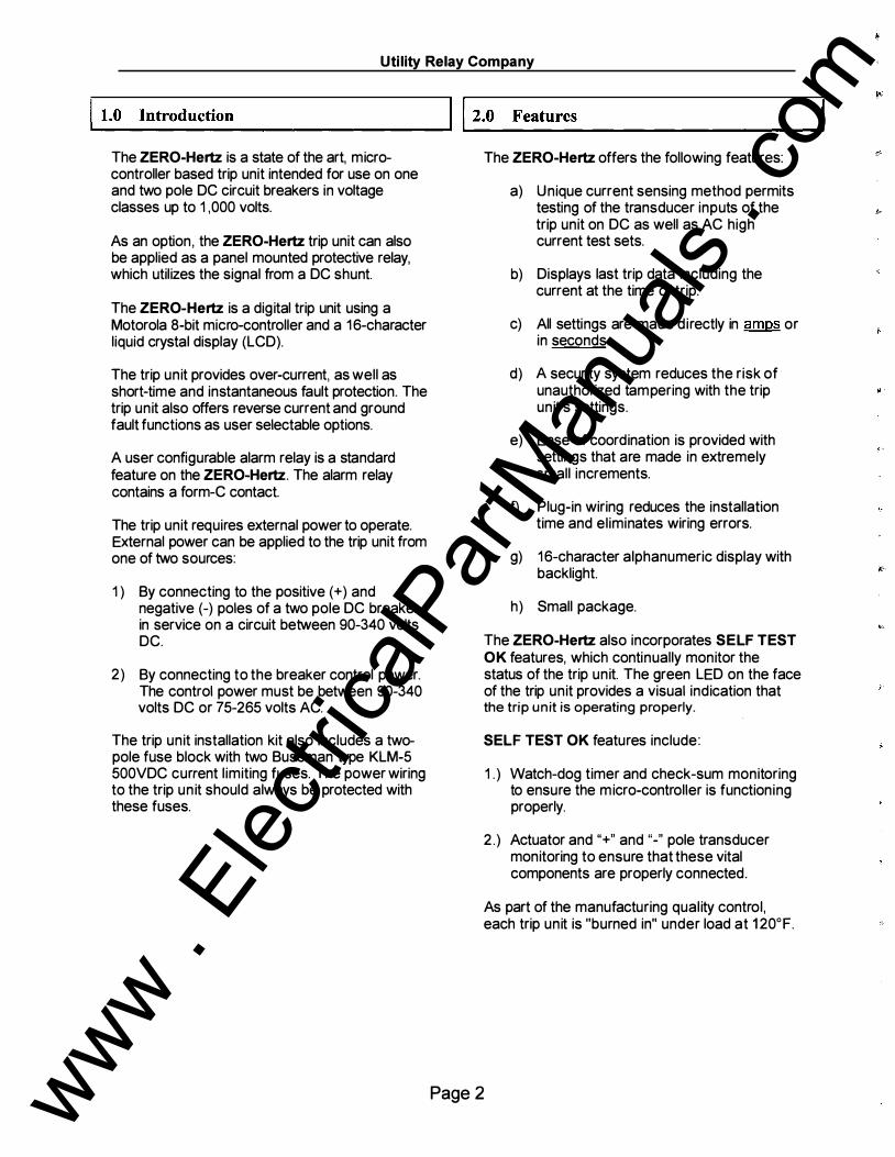
The ZERO-Hertz is a state of the art, microcontroller based trip unit intended for use on one and two pole DC circuit breakers in voltage classes up to 1 ,000 volts.
As an option , the ZERO-Hertz trip unit can also be applied as a panel mounted protective relay, which utilizes the signal from a DC shunt.
The ZERO-Hertz is a digital trip unit using a Motorola 8-bit micro-controller and a 16-character liquid crystal display (LCD).
The trip unit provides over-current, as well as short-time and instantaneous fault protection. The trip unit also offers reverse current and ground fault functions as user selectable options.
A user configurable alarm relay is a standard feature on the ZERO-Hertz. The alarm relay contains a form-e contact.
The trip unit requires external power to operate. External power can be applied to the trip unit from one of two sources:
1 ) By connecting to the positive (+) and negative (-) poles of a two pole DC breaker in service on a circuit between 90-340 volts DC.
2) By connecting to the breaker control power. The control power must be between 90-340 volts DC or 75-265 volts AC.
The trip unit installation kit also includes a twopole fuse block with two Bussman type KLM-5 500VDC current l imiting fuses. The power wiring to the trip un it should always be protected with these fuses.
Page 2
The ZERO-Hertz offers the following features:
a) Unique current sensing method permits testing of the transducer inputs of the trip unit on DC as well as AC high current test sets.
b) Displays last trip data including the current at the time of trip.
c) All settings are made directly in amps or in seconds.
d) A security system reduces the risk of unauthorized tampering with the trip unit's settings.
e) Ease of coordination is provided with settings that are made in extremely small increments.
f) Plug-in wiring reduces the installation time and eliminates wiring errors.
g) 16-character alphanumeric display with backlight.
h) Small package.
The ZERO-Hertz also incorporates SELF TEST OK features, which continually monitor the status of the trip unit. The green LED on the face of the trip unit provides a visual indication that the trip unit is operating properly.
SELF TEST OK features include:
1 . ) Watch-dog timer and check-sum monitoring to ensure the micro-controller is functioning properly.
2.) Actuator and"+" and "-" pole transducer monitoring to ensure that these vital components are properly connected.
As part of the manufacturing quality control, each trip unit is "burned in" under load at 120°F.
www . El
ectric
alPar
tMan
uals
. com

ZERO-Hertz, DC Trip Unit -Instruction Manual www.utilityrelav.com
�..1_2._1_ D_c _c_u_r _re_n_t _S _ e_n_s•_·n_g _______ ___.l l 2.2 UV O v erload trip The ZERO-Hertz uses an advanced Motorola micro-controller chip to perform the DC current calculations and to implement the logic functions.
The trip unit determines the DC current by measuring the true RMS current of the circuit. The trip unit samples at a 0.521 mill i-second rate during the sample period of 8.333 mil l i-seconds. For each sample period, the micro-controller performs the RMS calculation by squaring the current samples, finding the average of the square values and then taking the square root of the average. This value is then multiplied by the transducer or shunt rating to arrive at the current in amps.
This method of current sensing provides an extremely accurate measurement of DC current when applied on a DC circuit. This method also provides an equally accurate measurement of true RMS AC current when applied on a 60-Hertz AC circuit. This enables the transducer inputs of the trip un it to be tested on a high current DC or a 60-Hertz AC test set for LongTime, Short-Time, Instantaneous, Ground Fault and Reverse Current trip functions.
When the trip unit is applied on a two-pole breaker and two transducers are being used, the RMS calculation is performed individually for each pole of the breaker.
Page 3
The Under Voltage Overload (UV OL) trip function will produce a trip when the system voltage collapses during a low impedance fault. This is useful for those installations where the trip unit is powered by the system voltage.
Whenever the current is greater than two (2) times the L T Pick-Up setting and the trip unit power goes below the minimum required to operate the trip unit, a UV Overload trip is immediately initiated.
The user cannot turn off this feature.
www . El
ectric
alPar
tMan
uals
. com

Utility Relay Company
�...12_. _3_ G_ r_ou_n_d_ F_a_u_It _________ �,,2.5 Last Trip Data The ground fault feature of the ZERO-Hertz can only be implemented when two transducers are used with the trip unit, one on the positive (+) pole and one on the negative (-) pole of the breaker. The ground fault function is not available when using shunt input.
The trip unit measures the current of each pole individually and determines the ground current to be the difference between the absolute values of the current on the positive (+) and negative (-) poles measured in amps.
**** NOTE **** The trip un it can detect how many transducers are properly connected to it. The trip un it wil l only implement ground fault protection when it detects two transducers.
The ground fault feature is not available when using the shunt input.
12.4 1 6-Character Disp lay A 1 6-character dot matrix l iquid crystal display (LCD) is the interface between the trip unit and the user.
The dot matrix LCD is extremely versati le because it is capable of displaying not only numbers but also letters and symbols.
The LCD is used for the following purposes:
1 ) Entering the transducer or shunt input rating and making the pick-up and time delay settings with prompts from the display.
2) Displaying on demand, all trip unit settings.
3) Displaying on demand, the reason for the last trip and the current at the time of trip.
4) Continuously displaying the actual DC current on the circu it.
Page 4
After a breaker trip, the trip unit will save the trip data in its non-volatile EEPROM memory. The last trip data can be recalled later. This data is written over with the data from the next trip event.
The last trip data consists of the type of trip (i .e. , L T, ST, IN ST.. . . . ) and the associated DC current.
The abbreviations for the type of trip correspond to the following:
LT: ST: INST: GF: REVRS: UV OL: FORCED:
Long Time Short Time Instantaneous Ground Fault Reverse Current Under Voltage Overload Trip A trip initiated from a remote PC using the communications option.
A trip counter is also provided which indicates how many times the trip unit operated on each function.
The last trip data can be conveniently recalled at any time. See section 7.0, "Target Recall of Last rip Data" for further information.
See section 9.9 for instructions on erasing the last trip data.
www . El
ectric
alPar
tMan
uals
. com

ZERO-Hertz, DC Trip Unit -Instruction Manual www.utilitxrelav.com
.... 1_2 _.6 _ _ c_ u_ r_r_e_n_t _T _ r_a _n_s_d _u_c _er_ s _______ .........�l l 2. 7 Breaker Tripping
The transducer(s) provided with the trip unit are specifically designed to operate only with the ZERO-Hertz trip unit.
To provide maximum versatility, every transducer can be used interchangeably with any ZERO-Hertz trip unit. This simplifies ordering spare parts and eliminates the need to maintain costly inventory.
Depending on the breaker frame size and the transducer rating required, there are different values of transducer to choose from:
1. ) Low-Range Transducer is available for breakers requiring a transducer rating from 100 amps to over 3,000 amps.
2 . ) H i-Range Transducer is available for breakers requiring a transducer rating from 3,000 amps or less to 12,000 amps.
Each transducer has a user selectable current rating, which is determined at the time of installation (see Section 9.4).
**** NOTE ****
Each transducer is labeled with an arrow to indicate how it should be oriented if it is installed on the "+" pole.
It is important to install the "+" pole transducer so that the arrow on the transducer points in the same direction as the normal flow of current because the"+" pole determines current direction.
If the "+" pole transducer is not oriented properly, then the Reverse Current function (if implemented) will not function properly and a nuisance trip may occur.
The orientation of the transducer on the"-" pole is not important.
Page 5
The trip unit is designed to trip different breaker types in different ways.
Breakers equipped with a shunt trip device will be tripped when the trip unit momentarily energizes an auxiliary trip relay (included with the retrofit kit), which in turn will energize the shunt trip device on the breaker.
The contacts of the auxiliary trip relay are capable of "making" but not "breaking" the shunt trip current. The contacts must be wired in series with a breaker auxiliary contact, which will
"break" the shunt trip current when the breaker opens.
Breakers equipped only with the original electromechanical tripping devices will be tripped with a magnetically latched actuator included in the retrofit kit.
The trip unit discharges an internal capacitor to trip the actuator or momentarily energize the auxil iary trip relay.
www . El
ectric
alPar
tMan
uals
. com
Utility Relay Company
I 2.8 Al ar m Rel ay
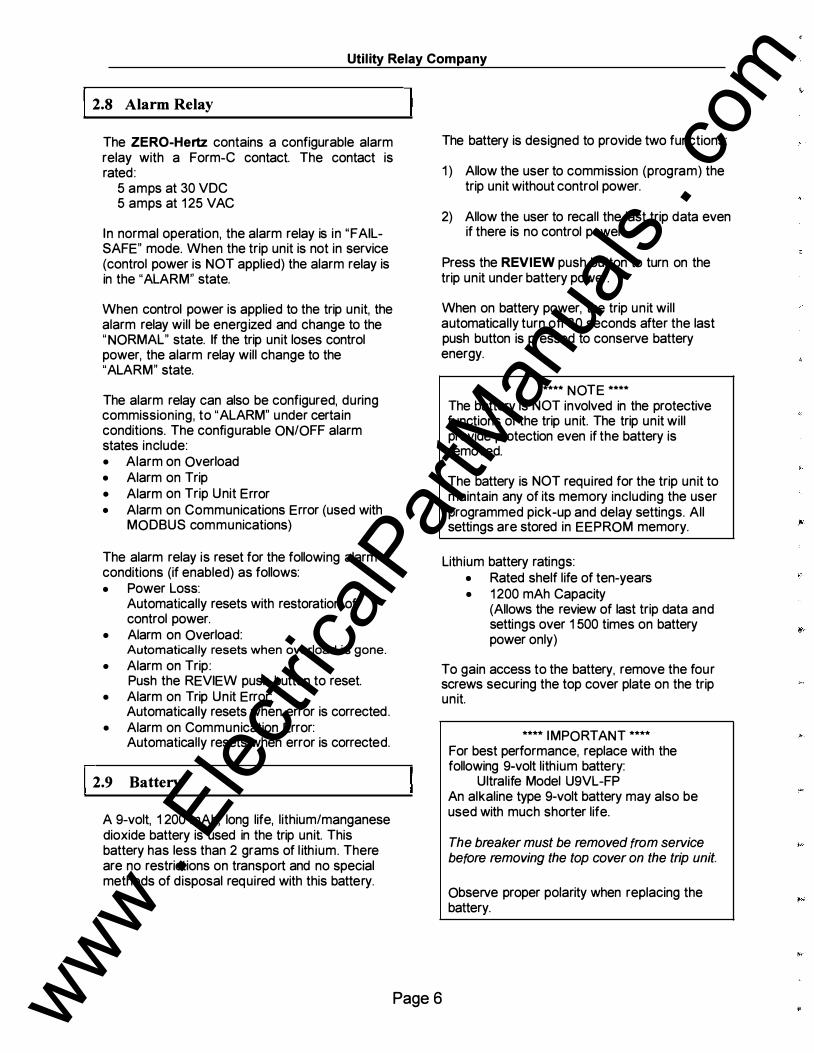
The ZERO-Hertz contains a configurable alarm relay with a Form-e contact. The contact is rated :
5 amps at 30 VDC 5 amps at 125 VAC
In normal operation, the alarm relay is in "FAILSAFE" mode. When the trip unit is not in service (control power is NOT applied) the alarm relay is in the "ALARM" state.
When control power is applied to the trip unit, the alarm relay will be energ ized and change to the "NORMAL" state. If the trip unit loses control power, the alarm relay will change to the "ALARM" state.
The alarm relay can also be configured, during commissioning, to "ALARM" under certain conditions. The configurable ON/OFF alarm states include: • Alarm on Overload • Alarm on Trip • Alarm on Trip Unit Error • Alarm on Communications Error (used with
MODBUS communications)
The alarm relay is reset for the following alarm conditions (if enabled) as follows: • Power Loss:
Automatically resets with restoration of control power.
• Alarm on Overload: Automatically resets when overload is gone.
• Alarm on Trip: Push the REVIEW push button to reset.
• Alarm on Trip Unit Error: Automatically resets when error is corrected.
• Alarm on Communication Error: Automatically resets when error is corrected.
I 2.9 Battery
A 9-volt, 1200 mAh, long life, lithium/manganese dioxide battery is used in the trip unit. This battery has less than 2 grams of l ith ium. There are no restrictions on transport and no special methods of disposal required with this battery.
The battery is designed to provide two functions:
1) Allow the user to commission (program) the trip unit without control power.
2) Allow the user to recall the last trip data even if there is no control power.
Press the REVIEW push button to turn on the trip unit under battery power.
When on battery power, the trip un it will automatically turn off 30 seconds after the last push button is pressed to conserve battery energy.
**** NOTE **** The battery is NOT involved in the protective functions of the trip unit. The trip unit will provide protection even if the battery is removed.
The battery is NOT required for the trip unit to maintain any of its memory including the user programmed pick-up and delay settings. All settings are stored in EEPROM memory.
Lithium battery ratings: • Rated shelf life of ten-years • 1200 mAh Capacity
(Allows the review of last trip data and settings over 1500 times on battery power only)
To gain access to the battery, remove the four screws securing the top cover plate on the trip unit.
Page 6
**** IMPORTANT **** For best performance, replace with the following 9-volt lithium battery:
Ultralife Model U9VL-FP An alkaline type 9-volt battery may also be used with much shorter life.
The breaker must be removed from service before removing the top cover on the trip unit.
Observe proper polarity when replacing the battery.
www . El
ectric
alPar
tMan
uals
. com

ZERO-Hertz, DC Trip Unit - Instruction Manual www.utilitvrelav.com
1�... _3._o _ _ o _p_t _io_n_ s _____________ _.l l 3. 1 Ex ternal Connections
The ZERO-Hertz is available in four d ifferent models.
The ZERO-Hertz can be supplied for use with either one or two transducers, or a DC shunt. MODBUS communications is also available.
ZERO-Hertz Trip Unit Models
ZERO-Hertz Transducer Communications
Trip Unit Part Inputs
Shunt Inputs (MODBUS)
Number
B-201 X B-202 X X B-203 X X B-204 X X X
Control power input
replaccbottcry
w1th brca�er outnfurvocc
@ � Rom"''''""•
MINUS Sf:.E INSTRUCTIONS Uocon!y9V-otylc
TRANSDUCER LJTIIIUMIMANGANiiSE
DIOX!DEBoncry
@
Top View of Trip Unit
The trip unit's external control power input is located on the left side of the top of the trip unit. For control power, the trip unit will accept: • 90 - 340 VDC • 75 - 265 VAC
The trip output for the actuator or trip relay is labeled ACTUATOR terminals, which are also located on the top of the trip unit.
I 3.2 Optional Connections
Depending on the specific model of the trip unit, all optional connections will be located on the bottom of the trip unit.
@
RS485 Communications port
Shunt input terminals
Bottom View of Trip Unit
All optional connectors are shown in the view above. These include:
@
• RS-485 Communication Port (left hand side) • Shunt Input Terminals (right hand side)
The alarm relay terminals, shown in the middle, are included on every model of the ZERO-Hertz trip unit.
Page 7 www . El
ectric
alPar
tMan
uals
. com

Utility Relay Company
I L- _3_. 3 __ c _o_ m
_m_u_n_i _c _a _ti _o _n _s _O..;p;;..t_i _o _n
______ _.l l 4.0 Security Key
The Optional RS-485 communications port uses the industry standard MODBUS RTU protocol . Multiple trip units can be daisy-chained together using a single twisted pair wire.
Information monitored includes: • DC current • Last trip data • Trip counter • Alarm conditions • Trip unit settings
The ZERO-Hertz also features remote programmabil ity, which al lows trip settings to be programmed remotely from a PC.
With the addition of URC's LCI (Local Communications Interface), ZERO-Hertz trip units can communicate directly across a local area network (LAN) .
For ZERO-Hertz trip units equipped with the Communications option, consult the AC-PRO+I ZERO-Hertz Communications Instruction Manual (PN: 1-COMM).
I 3.4 Shunt Input Option
The shunt input al lows signal input to the ZEROHertz directly from a DC shunt in the switchgear. The shunt input is used instead of the transducers as a means to measure the DC current.
During commissioning of the trip unit, the shunt input or the transducers are selected as the signal input for the trip unit. Section 5.0 details the procedure for commissioning a trip unit to use the shunt input.
The terminals on the bottom of the trip unit allow for direct connection to either a 50mV or 1 OOmV DC shunt.
Maximum recommended operating system voltage is 1 000 VDC. The internal isolation is 3750 VDC for 60 sec.
Page 8
The ZERO-Hertz trip unit contains a security feature that only al lows someone familiar with the operation of the trip unit to commission the trip unit or make changes to the settings
The "key" is simply a short jumper wire that is connected between the two terminals marked "KEY" on the top of the trip unit.
Jumper "KEY" to change settings
Remove cover to n:placebattery Wllhbn:al.cr
@
SH INSTRlX'TIONS Uuonly9V·•rylc I.ITinUM.'MASGANIOSic DIOXIDE&tlcey
To install the security key:
Jumper the two terminals labeled "KEY" on the top of the trip unit.
To remove the security key:
Remove the jumper wire.
The key al lows the user to commission the trip unit or to change the settings on a trip unit by performing the following steps:
1) Install the security key. This will put the trip unit in the programming mode.
2) Input settings to commission a new trip unit or change the settings on a previously commissioned trip unit (see Section 5.0) .
3) Remove the security key. This will save the new settings in the trip unit's non-volati le EEPROM memory.
**** IMPORTANT **** The security key must be removed prior to placing the breaker into service for the trip unit to function properly. The trip unit's display will prompt the user to remove the key.
@
www . El
ectric
alPar
tMan
uals
. com

ZERO-Hertz. DC Trip Unit- Instruction Manual www.utilitvrelav.com
�...l _s _.o __ c _o_ m
_m_i _s s _i _o _n _in_g
__________ ...... l l s. t Powering-Up The Trip Unit
Prior to placing the ZERO-Hertz trip unit into service, it must first be commissioned. This requires the user to enter all of the pick-up and delay settings into the unit before it will function. The commissioning process normally takes less than a few minutes to complete.
The ZERO-Hertz is commissioned as fol lows:
1) Install the security key (see Section 4.0)
2) Power-up the trip unit by pressing the REVIEW button (see Section 5 .1 ). The trip unit will alternately display the following:
ENTER DATA
SERIAL# XXXXXXX
3) Press the SAVE button to begin the commissioning process.
4) Enter the appropriate pick-up and delay settings (see Sections 5. 1 thru 5.23)
This same procedure is used to reprogram a trip unit that has already been commissioned.
Page 9
The ZERO-Hertz trip unit can be powered-up in either of the following two ways.
1. ) Internal Battery
Press the REVIEW button to power-up the trip unit using the internal battery.
While powered from the battery, the trip unit is designed to shut off automatically if none of the 4 push buttons on the face of the unit are pressed for 30 seconds. It is, therefore, best to have all the desired setting readily available before commissioning the unit when using the battery.
If the trip unit shuts down before the commissioning process is completed, the process must be started again from the beginning.
2 . ) External Power
Apply 90-340 VDC or 75-265 volts VAC to the external power terminals located on the top of the trip unit.
By applying external power, the unit will stay energized as long as necessary to complete the commissioning process.
When the trip unit is energized, the following will alternate on the display if the trip unit has not already been commissioned:
ENTER DATA
SERIAL# XXXXXXX
Press the SAVE push button to continue.
www . El
ectric
alPar
tMan
uals
. com

Utility Relay Company
I 5.2 Security Key During Co m m is s ioning
The following wil l be displayed if the security key is not already installed:
SECURITY KEY OFF
Instal l the security key to continue the commissioning process. See Section 4.0.
15.3 Trans ducer I Shunt Input Select
If the trip unit does not have the shunt input option, with the shunt connections on the bottom of the trip unit, proceed to Section 5.4
If the trip unit has the shunt input option, the following will be displayed:
IN PUT XDUCER
Where "XDUCER" represents the method of sensing current.
If the trip unit is going to be used with a transducer(s), press the SAVE button.
If the trip unit is going to be connected directly to a DC shunt as a method of sensing current, press the UP push button.
The following wil l be d isplayed:
I NPUT SHUNT
Press the SAVE button to continue.
**** NOTE ****
The DOWN button can be pressed to reselect the XDUCER inputs before pressing the SAVE button.
I I 5.4 Trans ducer I Shunt Rating
If the XDUCER input was selected, the following will be displayed:
XDUCER XXXXA
Where "XXXX" represents the transducer rating in amps.
If the SHUNT input was selected, the following will be displayed:
SHUNT XXXXA
Where "XXXX" represents the shunt rating in amps.
The XDUCER I SHUNT rating ranges from 100 amps to 5,000 amps in 25 amp steps, and from 5,000 amps to 12 ,000 amps in 250 amp steps.
The XDUCER/SHUNT rating entered into the trip unit must correspond to the actual rating of the shunt or the rating the transducer wil l be calibrated to. A security feature is provided so the XDUCER/SHUNT rating will not be accidentally changed later.
The security feature must be used to enter the initial XDUCERJSHUNT rating or to change the rating.
***To Activate the Security Feature***
• In the commissioning mode
• When the shunt or transducer rating is displayed
• Push and hold the REVIEW push button then push the SAVE push button. Release both push buttons
• This allows the transducer/shunt rating to be changed
With the security feature activated , press and hold the UP or DOWN button as required until the correct XDUCER I SHUNT rating is displayed.
Press the SAVE button to continue.
Page 1 0 ., www .
Elec
tricalP
artM
anua
ls . c
om

ZERO-Hertz, DC Trip Unit- Instruction Manual www.utilitvrelax.com
l .... s_.
_s_L
_o
_n
_g
_T
_.
_·m
_e
_(
_L
_T
_)
_P
_i
_ck
_-
_u
_p_Se
_t
_ti
_n
_g __ ___.l l s.6 .1 Long Ti m e (LT) Ther m al Me m ory
The following will be displayed:
L T PICK-UP XXXXA
Where "XXXX" represents the LT Pick-Up setting in amps. The L T Pick-Up setting ranges from 40% to 1 00% of the transducer rating. This setting is adjustable in 5 amp steps (50 amp steps for transducers greater than 5000 amp).
Press and hold the UP or DOWN button as required until the correct L T Pick-Up setting is displayed.
Press the SAVE button to continue.
I 5 .6 Long Ti m e (L T) Del ay Setting
The following will be d isplayed:
L T DELAY XX.XSEC
Where "XX.X" represents the LT Delay band. The L T Delay band is labeled by the number of seconds to trip at 6 times the L T Pick-Up setting.
The L T Delay setting ranges from 2 .5 to 30 seconds in steps of 0 .5 seconds. This provides 56 L T Delay bands.
Press and hold the UP or DOWN button as required until the correct L T Delay setting is displayed.
Press the SAVE push button to continue.
The following will be displayed:
L T THERMAL ON
If the Thermal Memory is desired, press the SAVE push button and go to Step 5.7 .
If the Thermal Memory is not desired, press the DOWN button and the following wil l be displayed:
L T THERMAL OFF
Thermal Memory ON mimics the cooling of cables after an overload. If the current goes above the L T PICK-UP with the Thermal Memory ON, the L T register starts at a value representing any retained heat in the cables from recent overloads and result in a faster trip.
With Thermal Memory OFF, an overload that drops below the L T PICK-UP will reset the L T register. If the current goes above the L T PICKUP again, the L T register starts from zero.
Press the SAVE push button to continue.
Page 1 1 www . El
ectric
alPar
tMan
uals
. com
Utility Relay Company
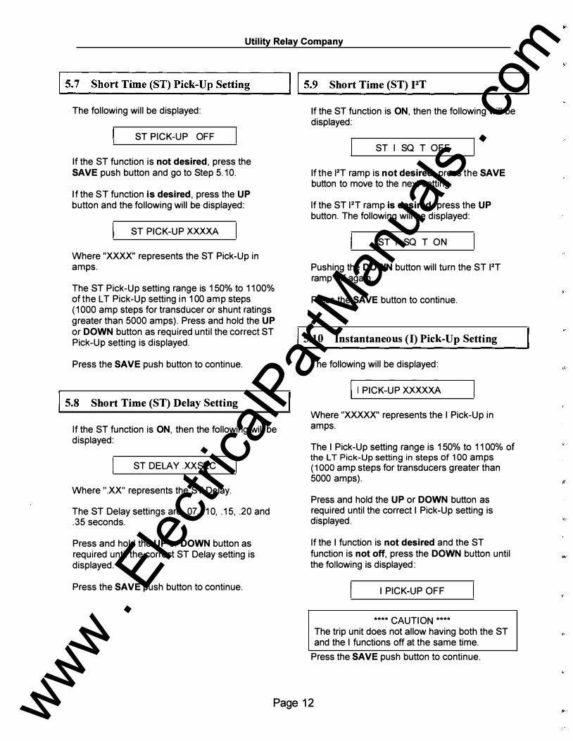
�...1 _5._7 _S_h _o _rt_T _im_ e_( S_T_) _P_i _ck _-_U_p _S_e _tt_in _g�-___.l l 5.9 Short Ti m e (ST) PT
The following will be displayed:
ST PICK-UP OFF
If the ST function is not desired, press the SAVE push button and go to Step 5. 10.
If the ST function is desired, press the UP button and the following will be displayed:
ST PICK-UP XXXXA
Where "XXXX" represents the ST Pick-Up in amps.
The ST Pick-Up setting range is 150% to 1100% of the L T Pick-Up setting in 100 amp steps (1000 amp steps for transducer or shunt ratings greater than 5000 amps). Press and hold the UP or DOWN button as required until the correct ST Pick-Up setting is displayed.
Press the SAVE push button to continue.
I 5.8 Short Ti m e (ST) Del ay Setting
If the ST function is ON, then the following will be displayed:
ST DELAY .XX SEC
Where ".XX" represents the ST Delay.
The ST Delay settings are . 07, . 1 0, . 15, .20 and . 35 seconds.
Press and hold the UP or DOWN button as required until the correct ST Delay setting is displayed.
Press the SAVE push button to continue.
If the ST function is ON, then the following will be displayed:
ST I SQ T OFF
If the 12T ramp is not desired, press the SAVE button to move to the next setting.
If the ST 12T ramp is desired, press the UP button. The following will be displayed:
ST I SQ T ON
Pushing the DOWN button will turn the ST I2T ramp off again.
Press the SAVE button to continue.
5.1 0 Ins tantaneous (I) Pick-Up Setting
The following will be displayed:
II PICK-UP XXXXXA
Where "XXXXX" represents the I Pick-Up in amps.
The I Pick-Up setting range is 150% to 1100% of the L T Pick-Up setting in steps of 100 amps (1 000 amp steps for transducers greater than 5000 amps).
Press and hold the UP or DOWN button as required until the correct I Pick-Up setting is displayed .
If the I function is not desired and the ST function is not off, press the DOWN button until the following is displayed:
I PICK-UP OFF
**** CAUTION ****
The trip unit does not allow having both the ST and the I functions off at the same time.
Press the SAVE push button to continue.
Page 1 2 www . El
ectric
alPar
tMan
uals
. com

ZERO-Hertz. DC Trip Unit -Instruction Manual
15.1 1 Ground Faul t (GF) Pick-Up Setting
If the XDUCER Inputs are selected, the following will be displayed:
GF PICK-UP OFF
If the GF function is not desired, press the SAVE push button and go to Step 5. 14.
If the GF function is desired, press the UP button and the following will be displayed:
GF PICK-UP XXXXA
Where "XXXX" represents the GF Pick-Up setting in amps.
The GF Pick-Up setting range is 40% to 200% of the transducer rating in steps of 10 amps.
Press and hold UP or DOWN button as required until the correct GF Pick-Up setting is displayed.
Press the SAVE push button to continue.
5.1 1 .1 Ground Faul t (GF) % Res traint
The GF Trip Function includes a percentage restraint feature to reduce the possibility of a nuisance GF trip when the breaker experiences high current such as during motor starting.
For currents greater than two times the transducer rating, the GF Pick-Up value is temporarily increased by 20% of the magnitude of the current above two times the transducer rating.
www.utilityrelay.com
1 15.1 2 Ground Faul t (GF) Delay Setting
If the GF function is ON, then the following will be displayed:
GF DELAY .XXSEC
Where ".XX" represents the GF Delay.
The GF Delay settings are . 1 0, .20, .30, .40 and .50 seconds.
Press and hold the UP or DOWN button as required until the correct GF Delay setting is displayed.
Press the SAVE button to continue.
15.1 3 Ground Faul t (GF) PT
If the GF function is ON, then the following will be displayed:
GF I sa T OFF
If the 12"f ramp is not desired, press the SAVE button to move to the next step.
If the GF 12"f ramp is desired, press the UP button. The following will be displayed:
GF I saT ON
Pushing the DOWN button will turn the GF 12T ramp off again.
Press the SAVE button to continue.
Page 1 3 www . El
ectric
alPar
tMan
uals
. com
Utility Relay Company
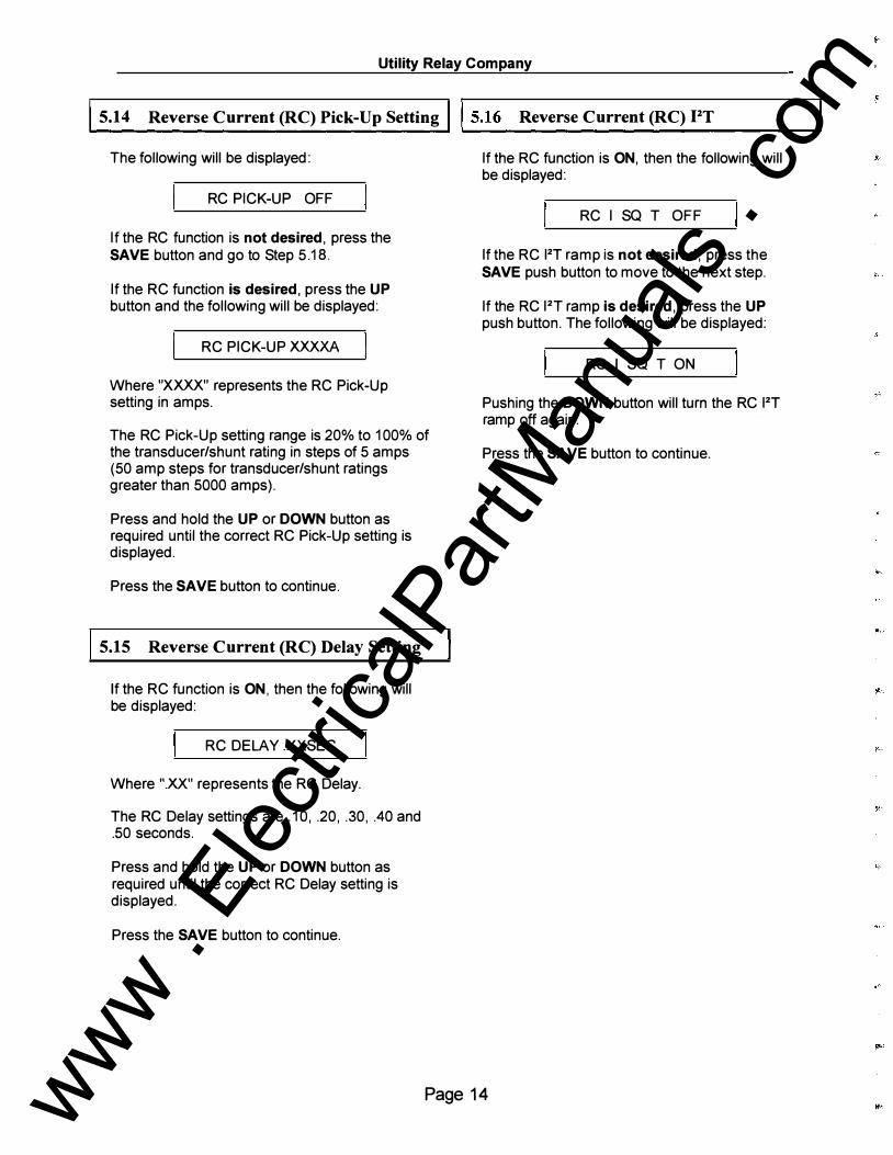
5.1 4 Revers e Current (RC) Pick-Up Setting 15.1 6 Revers e Current (RC) PT
The following will be displayed:
RC PICK-UP OFF
If the RC function is not desired, press the SAVE button and go to Step 5.18.
If the RC function is desired, press the UP button and the following will be displayed:
RC PICK-UP XXXXA
Where "XXXX" represents the RC Pick-Up setting in amps.
The RC Pick-Up setting range is 20% to 1 00% of the transducer/shunt rating in steps of 5 amps (50 amp steps for transducer/shunt ratings greater than 5000 amps).
Press and hold the UP or DOWN button as required until the correct RC Pick-Up setting is displayed.
Press the SAVE button to continue.
5.1 5 Revers e Current (RC) Delay Setting
If the RC function is ON, then the following will be displayed:
RC DELAY .XXSEC
Where ".XX" represents the RC Delay.
The RC Delay settings are . 10, .20, .30, .40 and .50 seconds.
Press and hold the UP or DOWN button as required until the correct RC Delay setting is displayed.
Press the SAVE button to continue.
If the RC function is ON, then the following will be displayed:
RC I SQ T OFF
If the RC I2T ramp is not desired, press the SAVE push button to move to the next step.
If the RC I2T ramp is desired, press the UP push button. The following will be displayed:
RC I SQ T ON
Pushing the DOWN button will turn the RC I2T ramp off again.
Press the SAVE button to continue.
Page 1 4
..
www . El
ectric
alPar
tMan
uals
. com

ZERO-Hertz, DC Trip Unit - Instruction Manual www.utilityrelay.com
�...l s_. _1 _7 _c_o_M _A _d_d_re _s_ s ________ ___.l l s. t8 Idle Line If the trip unit is NOT equipped with the communications option, proceed to Section 5.20.
If the trip unit is equipped with the communications option, then the following will be displayed:
COM ADDR XX
Where "XX" represents the trip unit communications address.
The address settings range from 1 to 127 in increments of 1 . This unique address will identify individual trip units connected on the same twisted pair wire.
**** NOTE ****
Each twisted pair wire can support up to 32 trip units. Multiple twisted pairs can support hundreds of trip units.
Press and hold the UP or DOWN button as required until the correct COM Address is displayed.
Press the SAVE button to continue.
The following will be displayed:
IDLE LINE ON
The Idle L ine setpoint enables the trip unit to operate properly with all manufacturers' computer hardware. This setpoint provides a method for the trip unit to determine that there is no communication on the twisted pair line (i.e. the line is IDL E), and that it is OK to transmit a message.
When Idle L ine is ON, the trip unit waits until the host PC releases the serial line after a transmission before it sends a reply message. This allows for faster communications with minimal dead time.
However, for some PCs, the serial line does not go to a known idle state when not driving the serial line. Therefore, Idle L ine circuitry in the trip unit cannot detect an Idle L ine state. In this case, the Idle L ine setpoint must be set to OFF. In this case, the trip unit waits a set delay time before sending a reply message. See the URC Communications Instruction Manual (Part Number: 1-COMM) for more details.
The factory default setting is ON. Press the UP button for ON or the DOWN button for OFF to select the appropriate Idle Line detection method.
Press the SAVE button to continue.
Page 1 5 www . El
ectric
alPar
tMan
uals
. com
Utility Relay Company
I�.... _s ._1_9_A_la_r_m_o _n _c_o_M ________ --Jjjs.21 Alar m on Trip
If the trip unit is equipped with the communications option, then the following will be displayed:
ALARM COM OFF
The factory default setting is OFF. Changing this setting to ON puts the alarm relay under the direct control of the communications port. The state of the relay is controlled directly from commands sent from a remote PC connected to the trip unit through this port.
With this setting ON, all other alarm relay settings are defeated except for loss of power. Proceed to Section 5.24 (Exit Procedure).
With this setting OFF all remaining alarm relay settings are enable. Proceed to Section 5.20.
Press the UP button for ON or the DOWN button for OFF.
Press the SAVE button to continue.
l s.20 Alar m on Overload
The following will be displayed:
ALARM OL OFF
If the Alarm on Overload feature is not desired, press the SAVE button and go to Step 5.21.
If the Alarm on Overload feature is desired, press the UP button and the following will be displayed:
ALARM OL ON
Press the SAVE button to continue.
**** NOTE **** Alarm on Overload, Alarm on Trip, and Alarm on ERROR, can be set to ON either individually or in any combination.
The following will be displayed:
ALARM TRIP OFF
If the Alarm on Trip feature is not desired, press the SAVE button and go to Step 5.22.
If the Alarm on Trip feature is desired, press the UP button and the following will be displayed:
ALARM TRIP ON
Press the SAVE button to continue.
Pushing the REVIEW push button will reset the Alarm on Trip.
!s.22 Al ar m on ERROR
The following will be displayed:
ALARM ERROR OFF
If the Alarm on ERROR feature is not desired, press the SAVE button and go to Step 5.23.
If the Alarm on ERROR feature is desired, press the UP button and the following will be displayed:
ALARM ERROR ON
If set to ON the Alarm on ERROR feature will operate the alarm if the SELF TEST OK LED on the front of the trip unit turns OFF for any reason while the trip unit is in operation. See Section 2.0.
Press the SAVE button to continue.
Page 1 6 www . El
ectric
alPar
tMan
uals
. com

ZERO-Hertz, DC Trip Unit- Instruction Manual
I 5 .23 Ex it Procedure
The following will be displayed:
SAVE IF DONE
REVIEW TO REVIEW
If it is desired to review the settings, push the REVIEW button. Make any changes necessary using the UP or DOWN buttons. As before, use the SAVE button to move to each new setting.
If the settings are as desired, push the SAVE button and the settings will be saved in the nonvolatile EEPROM memory.
The following will be displayed:
REMOVE KEY TO
COMMISSION UNIT
Remove the "key". See section 4.0.
If the commissioning process was performed using the internal battery, the unit will turn itself off.
If the commissioning process was performed while supplying external power to the trip unit, the following will be displayed:
LOW CURRENT
The commissioning process is complete.
Page 1 7
www.utilityrelay.com www .
Elec
tricalP
artM
anua
ls . c
om

Utility Relay Company
I 6.0 Changing Settings
**** IMPORTANT **** While it is possible to make changes to the settings with the breaker in service, it is strongly recommended that THE BREAKER S HOUL D BE REMOVED FROM SERVICE w�ile makin� these changes since the trip unit Will not prov1de protection during portions of this process.
Afte_r the trip unit is commissioned, settings can eas1ly be changed in the following manner.
Close the security key. See Section 4.0.
Powe_r up the trip unit by pressing REVIEW or by applymg external power as described in Section 5.0, Commissioning.
Press the REVIEW button. The following will be displayed:
ENTER DATA
SERIAL# XXXXXXX
Press the SAVE button.
Make any changes necessary using the UP or DOWN buttons. Use the SAVE button to move to each new setting.
After going through all the settings, the following will be displayed.
SAVE IF DONE
REVIEW TO REVIEW
If it is desired to review the setting, push the REVIEW push button. Make any changes necessary using the UP or DOWN buttons. As before, use the SAVE button to move to each new setting.
If the settings are as desired, push the SAVE button. The following will be displayed:
REMOVE KEY TO
COMMISSION UNIT
Remove the security key. See Section 4.0. The settings will be saved in the non-volatile EEPROM memory.
The Settings have been changed.
R�member that if the trip unit loses power during th1s process, the old settings will be retained and the process must be repeated.
Page 1 8 www . El
ectric
alPar
tMan
uals
. com

ZERO-Hertz, DC Trip Unit -Instruction Manual
17.0 Target Recal l of Las t Trip Data
The ZERO-Hertz has an especially useful Target Recall system.
After a breaker trip, the trip unit will display the type of trip (i.e. LT, ST, I, GF, UV OL or REVRS as applicable) and then the instantaneous current at the time of trip followed by the trip log and the settings. This information is saved in the non-volatile EEPROM memory and is available immediately after a trip or anytime thereafter.
**** NOTE **** Only the data from the last trip is saved. The second time the breaker trips, the new trip data is written over the first trip data.
Pressing the REVIEW button will display the following two alternating messages, alternating at a 1.0 second interval rate:
I LAST TRIP XX
I xxxxx AMP
Where "XX" is the type of tripping event (i.e. L T, ST, I, GF, UV FAULT or REVRS as applicable) and "XXXXX" is the magnitude of the current at the time of trip. If the breaker has two poles and two transducers are connected to the trip unit, then the current value displayed will be the greater of the two poles.
Pressing the REVIEW button again will display the following two alternating messages, alternating at a 1.0 second interval rate:
HOL D <REVIEW> TO
VIEW TRIP COUNTS
www.utilitvrelay.com
If the REVIEW key is pushed again and held down for more than 2 seconds, the trip counter memory is accessed and the following will be displayed
INST TRIPS: XX
The "XX" represents the number of times the trip unit has tripped on the Instantaneous function.
Each successive press of the REVIEW button will display the number of trips for the additional functions as follows:
LT TRIPS: XX
ST TRIPS: XX
GF TRIPS: XX
FORCE TRIPS: XX
REVRS TRIPS: XX
UV OL TRIPS: XX
Continuing to press the REVIEW button will step through a review of the settings that are currently programmed in to the trip unit.
**** NOTE **** Pushing the SAVE, UP or DOWN buttons during "target recall" has no effect because the "key" is not on. No settings can be changed without using the "key".
To erase the L ast Trip Data and the trip counter from memory, refer to Section 9.9. After the L ast Trip Data has been erased, pressing the REVIEW button will display the following:
NO LAST TRIP
Page 1 9 www . El
ectric
alPar
tMan
uals
. com

Utility Relay Company
ls.o Nor m al Operation
Breaker Current Less than 20% of Transducer/Shunt Rating:
With the trip unit in service, and the breaker current less than 20% of the transducer/shunt rating, the display will show the following:
I LOW CURRENT
Breaker Current Greater than 20% of Transducer/Shunt Rating:
If the breaker current is greater than 20% of the transducer/shunt rating but less than the L T pick-up value or GF pick-up value (if applicable}, the following will be shown on the display.
I CURRENT xxxxx A
When the trip unit detects an overload situation, the "PICK-UP" light on the front of the trip unit will illuminate, and the following will alternately be shown on the display at . 5 second intervals:
I CURRENT xxxxx A
OVERLOAD
9.0 Tes ting & Calibration- Trans ducers Inp ut
**** WARNING **** Always REMOVE FUSES from the fuse block supplying power to the trip unit when testing the breaker. This includes high current injection testing, meggering or any other test, which requires energizing the breaker stabs or control wiring supplying power to the trip unit.
Failure to REMOVE FUSES while testing can result in permanent damage to the trip unit.
Be sure to REPLACE FUSES before placing the breaker in service.
A "primary injection" test is recommended as the initial test of the ZERO-Hertz retrofit. If a DC high current test set is available, it should be used for calibration and all functional tests of the trip unit.
If an AC high current test set is the only type available, it should be used for calibration and to test the trip unit's pick-up, timing accuracy and repeatability for the Long-Time, Short-Time, Instantaneous, Reverse Current and Ground Fault functions.
When testing the trip unit, it is important to remember that the trip unit requires control power to operate during calibration and testing. To power the trip unit, simply remove the wires that connect the trip unit power inputs to the breaker stabs or control wiring and apply a suitable power source to those two terminals on the trip unit. Be sure to observe the control power voltage range, which is clearly marked above the terminals on the top of the trip unit.
Page 20
**** WARNING **** Only apply control power to the terminals clearly marked as the Power Input on the top of the trip unit. Also observe the voltage restrictions marked on the top of the trip unit.
DO NOT apply power to any other terminals on the trip unit. Applying power to any terminals other than the Power Input terminals will cause SEVERE DAMAGE and voids the warranty of the trip unit.
www . El
ectric
alPar
tMan
uals
. com

ZERO-Hertz. DC Trip Unit- Instruction Manual
19.1 Step 1: Commission the Trip Unit Before proceeding with the normal primary injection tests, the trip unit must be . commissioned to make it functional. See Sect1on 5.0 for the commissioning procedure. It is best to use the final pick-up and time delay settings if they are known. If not, use typical settings for the primary injection test.
It is important to remember that control power must be applied to the trip unit during primary injection testing. 1 20VAC can be used.
9.2 Step 2: Verify Transdu cer Installation INSTALLATION ON A ONE POLE BREAKER
It is important to verify that the transducer is properly ori�nted on the breaker bus with re
.�a�d
to the direct1on of the flow of current on the + pole of the breaker.
To ensure proper transducer orientation, verify that the label on the side of the transducer (shown below) is oriented such that the arrow points in the same d irection as the flow of current ( i .e. from the source to the load) on the
"+" pole of the breaker.
Load Line + POLE CURRENT
Improper orientation of the transduce� on the "_+"
pole will result in a reverse current nu1sance tnp if the Reverse Current (RC) function is on.
If the transducer is not oriented properly on the breaker bus, unscrew the transducer from the bus, rotate the transducer 1 80 degrees and refasten to the bus using the existing screw. It will be necessary to re-calibrate the transducer if it must be repositioned on the bus (see section 9.4).
Also verify that the transducer is connected to the "+ TRANSDUCER" input on the top of the trip unit.
www. utility relay .com
If the transducer is not properly connected, the trip unit's LCD will d isplay:
CH ECK XDUCERS
until the connection is correct. The SELF TEST OK LED will be off until the connections are correct.
**** NOTE ****
The Ground Fault (GF) function can only be implemented on a two pole breaker with both the "+" and "-" transducers connected. If the GF function was turned ON during the commissioning process, the trip unit will automatically defeat this function if only the "+" transducer is being used.
The GF feature is not available for shunt input.
INSTALLATION ON A TWO POLE BREAKER
The ZERO-Hertz trip unit can be installed on a two pole breaker with only one transducer by installing the transducer on the "+" pole of the breaker. However, an addition transducer must also be used on the"-" pole of the breaker in order to implement the Ground Fault (GF) function.
It is important to verify that the transducers are properly oriented on the breaker bus with regard to the direction of the flow of current. To ensure proper transducer orientation, check the following:
1 . ) For the transducer installed on the"+" pole of the breaker; verify that the label on the side of the transducer (shown below) is oriented such that the arrow at the side of the label points in the same direction as the flow of current on the "+" pole (i .e. from the source to the load).
2 . ) For the transducer installed on the"-" pole of the breaker, the orientation of the transducer does not matter since this transducer is not used to detect current direction. Only the absolute value of the current is determined and used to calculate the Ground Fault current.
Also verify that the transducer installed on the "+" pole is connected to the "+ SENSOR" input on the top of the trip unit.
Page 21 www . El
ectric
alPar
tMan
uals
. com
Utility Relay Company
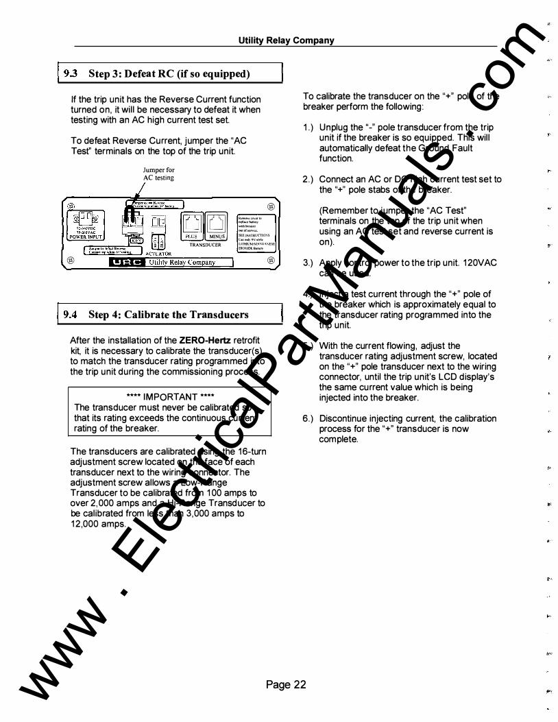
19.3 Step 3: Defeat RC (if so equip p ed) If the trip unit has the Reverse Current function turned on, it wil l be necessary to defeat it when testing with an AC high current test set.
To defeat Reverse Current, jumper the "AC Test" terminals on the top of the trip unit.
Jumper for AC testing
rc:pl�ebanery wuhbreal..er !lii!OfsCIVIe<:
@
� •=�'�'·" MINUS SEE INSTRUC.TIO�S l:•coni)9V-stvle
TRANSDUCER LITHILlvt�IAXG�"'ESE DIOXIDEBatlcJY
@
19.4 Step 4: Calibrate the Transducers After the installation of the ZERO-Hertz retrofit kit, it is necessary to calibrate the transducer(s) to match the transducer rating programmed into the trip unit during the commission ing process.
**** IMPORTANT **** The transducer must never be calibrated so that its rating exceeds the continuous current rating of the breaker.
The transducers are calibrated using the 16-turn adjustment screw located on the face of each transducer next to the wiring connector. The adjustment screw al lows a Low-Range Transducer to be calibrated from 1 00 amps to over 2,000 amps and a Hi-Range Transducer to be calibrated from less than 3,000 amps to 1 2 ,000 amps.
@
To calibrate the transducer on the "+" pole of the breaker perform the following:
1 . ) Unplug the"-" pole transducer from the trip unit if the breaker is so equipped. This wil l automatically defeat the Ground Fault function.
2 . ) Connect an AC or DC high current test set to the "+" pole stabs of the breaker.
(Remember to jumper the "AC Test" terminals on the top of the trip unit when using an AC test set and reverse current is on).
3.) Apply control power to the trip unit. 1 20VAC can be used.
4.) Inject a test current through the "+" pole of the breaker which is approximately equal to the transducer rating programmed into the trip unit.
5 . ) With the current flowing, adjust the transducer rating adjustment screw, located on the "+" pole transducer next to the wiring connector, until the trip un it's LCD d isplay's the same current value which is being injected into the breaker.
6 .) Discontinue injecting current, the calibration process for the "+" transducer is now complete.
Page 22 www . El
ectric
alPar
tMan
uals
. com
ZERO-Hertz, DC Trip Unit -Instruction Manual www.utilityrelay.com
For a two pole breaker with two transducers, the "-" pole transducer must be calibrated as follows:
1 . ) U nplug the "+" pole transducer from the trip unit. This will automatically defeat the Ground Fault function. NOTE: The "SELF TEST OK" LED on the trip unit will go out.
2.) Connect an AC or DC high current test set to the "-" pole stabs of the breaker.
3 . ) Apply control power to the trip unit. 1 20VAC can be used.
4 . ) Inject a test current through the "-" pole of the breaker which is approximately equal to the transducer rating programmed into the trip unit.
5.) With the current flowing, adjust the transducer rating adjustment screw, located on the "-" pole transducer next to the wiring connector, until the trip unit's LCD display's the same current value which is being injected into the breaker.
6 . ) Discontinue injecting current, the calibration process is now complete.
When the calibration process is completed, make sure that all of the transducer cables are properly reconnected.
I 9.5 Step 5: Defeat GF (if so equip p ed) If the trip unit is equipped with the Ground Fault function, it will be necessary to defeat ground fault trip to test the remainder of the functions by injecting current through both transducers. Jumper the load stabs of the breaker and inject current into the two line stabs.
As an alternate method, the cable going to the transducer on the pole NOT being tested can be temporarily removed. This will turn off the GF function.
To test the Ground Fault function, inject current from the line to the load stabs on one pole of the breaker with both transducers connected.
9 .6 Step 6: Verify Pick-Up and Calibration To test the L T Pick-Up, increase the current until the "Pick-Up" LED illuminates. Observe that the injected current corresponds to the programmed L T Pick-Up setting.
Page 23 www . El
ectric
alPar
tMan
uals
. com

Utility Relay Company
19.7 Step 7: Pr imary Inj ection Tests Proceed with the normal primary injection test to verify the pick-up and time delay of the various trip functions. The pick-up and time values should be within the tolerance band of the ZERO-Hertz time-current curves.
When testing the time delay of a trip function, the test current must be at least 1 0% greater than the pick-up setting for that function.
9.8 Step 8: R ev er se Curr ent (RC) Testing When using an AC high current test set, installing a jumper wire as shown below can test the Reverse Current (RC) function. This forces the trip unit to consider the "+" pole current as reverse current.
Remove .:over to
replace battery
out ofoervtce
®
SEE P.\STRC<TIO!'<S
l"sc only 9V-•tyl�
LITHIUM'MASGA��SE
Jumper to test Reverse Current trip
DIOXIDE Battery
Proceed with the normal primary injection test to verify the pick-up and time delay of the RC function . The pick-up and time values should be within the tolerance band of the ZERO-Hertz time-current curves.
The direction of current flow is only determined by the "+" pole. Do NOT try to test the "-" pole for the RC trip function.
®
Page 24 www . El
ectric
alPar
tMan
uals
. com
ZERO-Hertz, DC Trip Unit- Instruction Manual
I 9. 9 Step 9: E rase Last Trip Data After completing the primary injection test, it is important to erase the last trip data from the memory of the trip unit.
**** IMPORTANT **** Erase the last trip data from the memory of the trip unit after completing the primary injection tests.
To erase the memory in the trip unit after completing the primary injection tests, use one the following methods:
Method 1 :
1 ) The trip unit should not be powered-up.
2) Install the security key. See section 4.0.
3) Push and hold both the UP and DOWN push buttons.
4) While continuing to hold the UP and DOWN buttons, push the REVIEW button. Release all buttons. The following will be d isplayed:
UN-COMMISSION?
5) If the settings made during the commissioning procedure are to be erased, press the UP button. If the settings are not to be erased, push the DOWN button.
6) The following will be d isplayed:
ERASE LAST TRIP?
7) If the last trip data is to be erased, press the UP button. If the data is not to be erased, push the DOWN button.
8) The trip unit wil l turn OFF. Remove the security key. All appropriate changes are completed.
www.utilitvrelav.com
Method 2:
1 ) With the unit powered-up, press the REVIEW button until the last trip data is d isplayed.
2) Push and hold in both the UP and DOWN buttons.
3) While continuing to hold the UP and DOWN buttons, push the SAVE button to clear the last trip data. The following will be displayed:
NO LAST TRIP
Last Trip Data has been erased.
**** IMPORTANT **** If the last trip data is not erased after the primary injection test, the operating personnel may later assume that the breaker interrupted a fault at some time in the past when they check the last trip data.
10.0 Testing - Shunt Inp ut Primary injection testing is usually not practical when shunt input is used.
Accurate pick-up and timing tests of the shunt input can be made using Utility Relay Company's ZERO-Hertz Secondary Injection Test Set.
Alternatively, other test equipment that provides an adjustable milli-Volt signal can be used.
The recommended signal rages are: 50 mil l i-Volt Shunt: 0 to 500 mil l i-Volt 1 00 milli-Volt Shunt: 0 to 1 000 milli-Volt
Page 25 www . El
ectric
alPar
tMan
uals
. com
Utility Relay Company
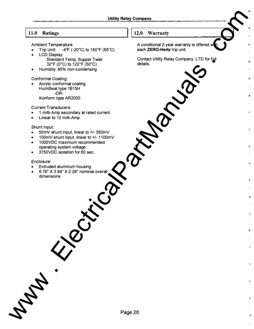
...._ll _. _o _R_at _i _n_g s ___________ ---al l t2.0 W arranty Ambient Temperature: • Trip Unit: -4°F (-20°C} to 1 50°F (65°C} • LCD Display:
Standard Temp, Supper Twist 32°F (0°C} to 1 22°F (50°C}
• Humid ity: 95% non-condensing
Conformal Coating: • Acrylic conformal coating
H umiSeal type 1 81 5H -OR-
Konform type AR2000
Current Transducers: • 1 mi lli-Amp secondary at rated current. • Linear to 1 2 mi l li-Amp
Shunt I nput: • 50mV sh unt input, l inear to +/- 550mV • 1 OOmV shunt input, linear to +I- 1 1 OOmV • 1 OOOVDC maximum recommended
operating system voltage • 3750VDC isolation for 60 sec.
Enclosure: • Extruded aluminum housing • 6. 76" X 3 .84" X 2 .28" nominal overall
dimensions
A conditional 2-year warranty is offered with each ZERO-Hertz trip unit.
Contact Utility Relay Company, L TO for ful l details.
Page 26 www . El
ectric
alPar
tMan
uals
. com

ZERO-Hertz, DC Trip Unit -Instruction Manual www.utilitvrelay.com
I�... _1 _3. _o _ _ T _im_e_-c_ u_ r_r_e _n _t _C _ u_rv_e ______ ---11 1 13.1 L T Trip Time The Time-Current curves are shown on the last pages of this manual.
The curves are shown on a 4 X 5 log-log graph with seconds in the vertical direction and normalized current in the horizontal direction.
Overload and fault currents are shown as multiples of the L T pick-up setting. Ground and Reverse currents are shown as a percentage of the transducer rating.
The curves for the following time bands: LT ST I2T GF IZT RC 12T
are based on the following equation:
12T = Constant
Where: I is current in amps T is time to trip in seconds (center of the band)
The tolerance for the bands is ± 1 0% in the current direction. Based on the Time vs. Current trip equation (12T = Constant) for the L T trip function, the mathematical tolerance in the time direction for LT is +23.5% and -1 7 .4%. The tolerances in the time direction for the other functions are graphically shown on the TimeCurrent curves.
For overload currents, the above equation can be restated as follows:
T = TBCLr divided by X2
Where: T = time to trip in seconds (center of the band)
X = current in multiples of the L T pick-up setting
TBCL r = the L T Time Band Constant = 36 X L T time band setting
**** NOTE **** The LT Time Band Constant (TBCLT) = 36 X The L T Time Band Setting in seconds.
EXAMPLE #1 :
Transducer Rating L T pick-up LT time band Test Current
1 600A 1 200A 20S 3600A
TBCLr = 36 X LT Time Band Setting = 36 X 20 = 720
and X = 3600A /1 200A = 3
Therefore: trip time = T = TBCLr I X2 or 720/32 = 720/9 = 80 seconds
**** NOTE **** To determine the L T trip time by calculation :
1 ) Calculate the L T Time Band Constant (TBCLr)
2) Calculate "X" where: X = (test current)
(L T Pick-Up Setting) 3) Solve the equation:
trip time(sec) = TBCLr divided by X2
Page 27 www . El
ectric
alPar
tMan
uals
. com
Utility Relay Company
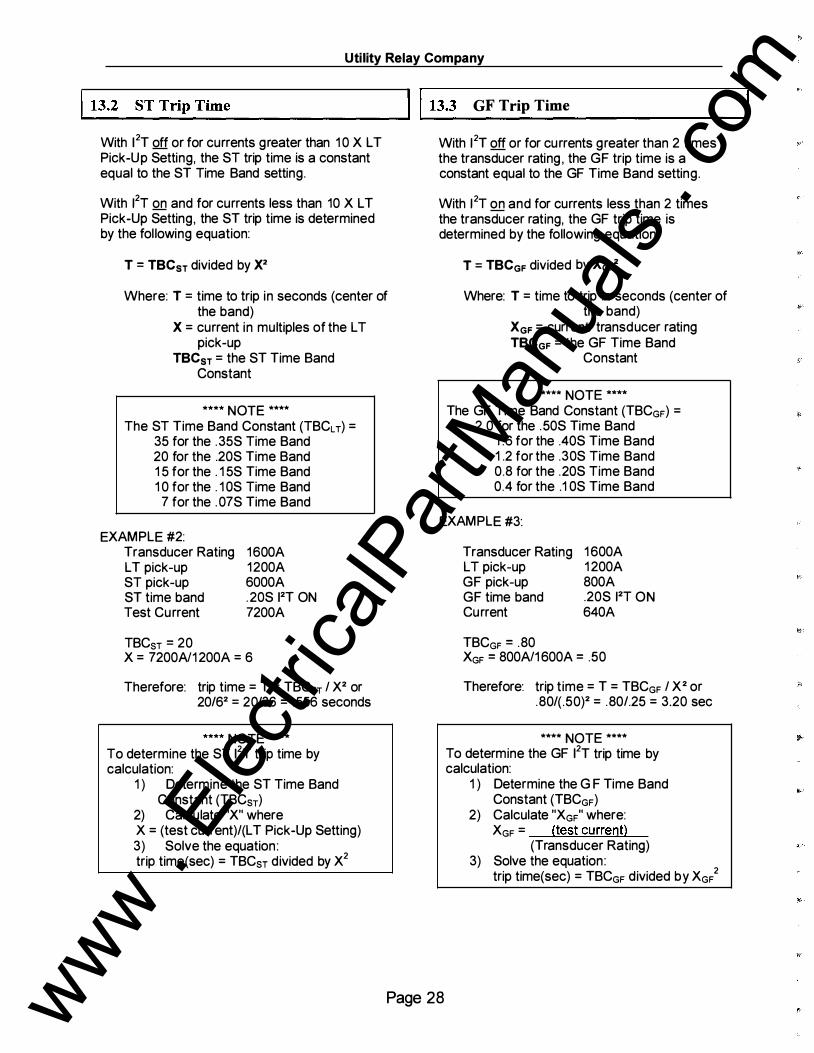
�.....-13_. _2_S_T_T_r_ip_T_i _m_e _________ ...... l l 13.3 GF Trip Time With 12T off or for currents greater than 1 0 X L T Pick-Up Setting, the ST trip time is a constant equal to the ST Time Band setting.
With 12T on and for currents less than 10 X L T Pick-Up Setting, the ST trip time is determined by the fol lowing equation:
T = TBCsr divided by X2
Where: T = time to trip in seconds (center of the band)
X = current in multiples of the L T pick-up
TBCsr = the ST Time Band Constant
**** NOTE ****
The ST Time Band Constant (TBCLr) = 35 for the .35S Time Band 20 for the .20S Time Band 1 5 for the . 1 5S Time Band 1 0 for the . 1 OS Time Band
7 for the . 07S Time Band
EXAMPLE #2: Transducer Rating LT pick-up ST pick-up ST time band Test Current
TBCsr = 20
1600A 1200A 6000A .20S 12T ON 7200A
X = 7200A/1 200A = 6
Therefore: trip time = T = TBCsT I X2 or 20162 = 20136 = .556 seconds
**** NOTE ****
To determine the ST 12T trip time by calculation:
1 ) Determine the ST Time Band Constant (TBCsT)
2) Calculate "X" where X = (test current)I(L T Pick-Up Setting) 3) Solve the equation : trip time(sec) = TBCsT divided by X2
With 12T off or for currents greater than 2 times the transducer rating , the GF trip time is a constant equal to the GF Time Band setting.
With 12T on and for currents less than 2 times the transducer rating, the GF trip time is determined by the following equation:
T = TBCGF divided by XGF2
Where: T = time to trip in seconds (center of the band)
XGF = currenU transducer rating TBCGF = the GF Time Band
Constant
**** NOTE ****
The GF Time Band Constant (TBCGF) = 2.0 for the .50S Time Band
1 .6 for the .40S Time Band 1 .2 for the .30S Time Band 0.8 for the .20S Time Band 0.4 for the .1 OS Time Band
EXAMPLE #3:
Transducer Rating LT pick-up GF pick-up GF time band Current
TBCGF = .80
1 600A 1 200A 800A .20S 12T ON 640A
XGF = 800A/1 600A = .50
Therefore: trip time = T = TBCGF I X2 or .801( .50)2 = .801.25 = 3.20 sec
**** NOTE ****
To determine the GF 12T trip time by calculation:
1 ) Determine the G F Time Band Constant (TBCGF)
2) Calculate "XGF" where: XGF = (test current)
(Transducer Rating) 3) Solve the equation :
trip time(sec) = TBCGF divided by XGF2
Page 28 www . El
ectric
alPar
tMan
uals
. com

ZERO-Hertz. DC Trip Unit- Instruction Manual www. utilityrelay .com
Long Time (L T) P 5 amp steps ick-Up
Rating
1000
---40% to 1 00% of Transducer/Shunt (50 amp steps for > 5000 amp Trans ducer/Shunt)
100
1 50% ST Pick-Up -
ick-Up teps
Short Time (ST) P OFF & 1 00 amp s 1 50% to 1 1 00% o LT Pick-Up
f
r
1 0
VJ 0 � ( 1 000 amp steps fo > 5000 amp Trans ducer/Shunt) &l
Instantaneous (I) Pick-Up OFF & 1 00 amp steps 1 50% to 1 1 00% of LT Pick-Up ( 1 000 amp steps for > 5000 amp Transducers)
VJ
I
. I
ST 1 2 T OFF / -
1 50% I Pick-Up-
.O J
I X '" \
ZERO-Hertz DC Trip Unit Overload Time Current Curve
2X 4X 6X l OX 20X , I
�
r.,..
, I
i LT Delay '
� , 0. 5 sec. steps / \.."( ! 2.5 to 30.0 sec. I i I @ 6X LT Pick-Up ,
l J ! ! ! 1
, I I I , I l . 1 1 I -" I 1\\ i l i l i i I I i I i 1 1 1 !
I i I I 1 , , I i I L 1\ 't '
\ \ � P\\ \ \ H- ! \ 1\ \ i I
I ' I ' ,
J , I I I ll
1 1
i I I I !
. ,
I I I
I I I
I i .
-
/
--
I ! r-
I X
i\\ ' J I j i l l \U 6X L T Pick-Up � , , I ' I
I� I I �\ I I i
·� .... \ '"" \ I 0 ' ., '/. I � ..., "" ' \ 4+ �
i\ I �
i
1 1 , l1 I I I ; 1 ) 1 I I I i I I i i
! I ' I i l 1 ' I
1--- 1 100% ST Pick-Up [ I I I I I i I I I i ! I I ! ST Delay I , I I I
with & without I 2 T • � ,\ " � .... ., r-B '"" � 9t. ' 1\ '",;;. -� 9t. .... '""
J ! 1 [ _/ ST I 2 TbN I , ' I ,
1 100% I Pick-Up --._
__i .35s�c "'i',
.20sec t i . 1 5sec 1 �FI- I . ! Osee I
i .07sec
2X 4X 6X ! OX 20X
L l
l l llll i I I I I I I I . I l l
J _L_i ! !
I I ! ' I I I I ! �1-" i I 1 i
I I I i 1 1 I l
Current in Multiples of Long Time Pick-Up
Figure 1 3.4 Overload TCC
Page 29
1000
1 00
1 0
VJ 0 � u u.l VJ
. I
.01
www . El
ectric
alPar
tMan
uals
. com

Utility Relay Company
TH IS PAGE I NTENTIONALLY LEFT BLAN K
Page 30 www . El
ectric
alPar
tMan
uals
. com
ZERO-Hertz, DC Trip Unit- Instruction Manual www.util itvrelay.com
1 000
1 00
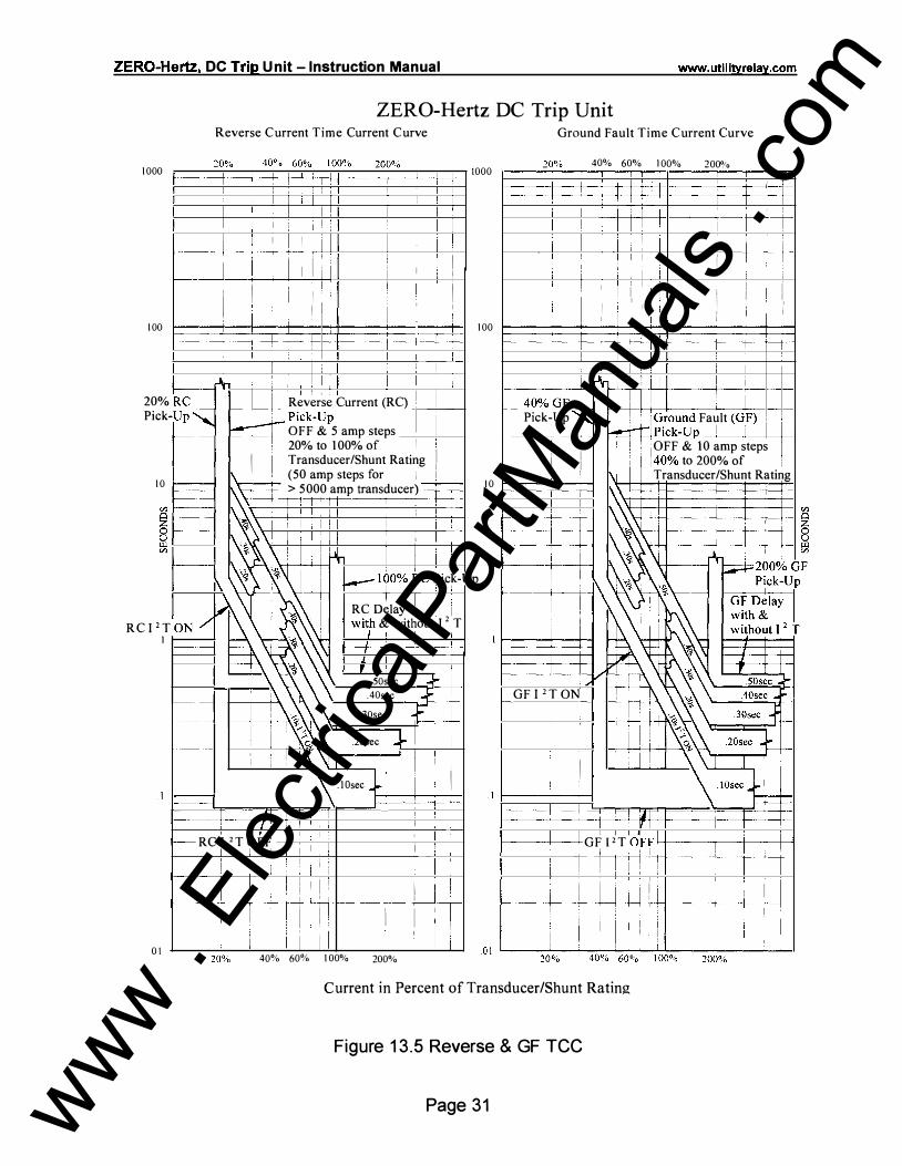
ZERO-Hertz DC Trip Unit Reverse Current Time Current Curve
-
I I I I ! ! I I '
' ' I I I I
I I ! I I ! I I �----+-·---t----r-----· ' �---1-J_l l I I i I I I I I i I : I I I ! I i
I ' I ! I
-
i I
I I I I I I I
I 1----r+ I Rever'se Current (RC) I
I I
i I ! I ! I I I
'
I I
j
1000
i - !
Ground Fault Time Current Curve
40% 60% I 00% 200°'o ' . ! __I_ J I I I I I
T
i . I I I I I i 1 i I i I I : I : I I i i I ' I I, ! : I I II II I I i I i I I i I 1 00 �==t=t=t=t=t=ti=tt==t==t=t=s
_j_ r\ . : L ! I RC
_�
-Up ' 20% Pick � Pick-Up I 11
r--- 40% GF +-- j ll ! l ! I Pick�Up ')-.... 1 1 ! : 1 G_round Fault (G,F) j I! I �IP1ck-Up -�1 �1--1 +--+--1
1 0
RC I 2 T I
0 1
1-------
1-------1-----1-------1-----
1--
ON /
1-----·--
--
OFF & 5 amp steps 20% to 1 00% of I I I
I ! Transducer/Shunt Rating I I I\ (50 amp steps for I I 1.\-t---i > 5000 amp transducer)
,\ I I �,\ i ! ·\! i 1 I � \ I I
\ w � -�
·--t-- � I I 11 ":.I i � :
: I I '\ I I
I I ! � I i I 1 I ' .!. ;_ !
1--- 190% �c Pic�-
Rc Delay \ I 1 wi�h & without I 2 T
,
I I I
.50sec --11-- I .40sec Ii i .30sec !
.20sec ..,L- I I I I I \ l Osee .,l i I I - -' ' �--+---+--!+--' I
1---- RC I 2 T OFF I I !
! ' f--------i--1 r---_j__ I i
i
I i
I I
I I I I ! ' J I ; I I I I ! ! ' ! I
I I I I 1 1
40% 60% 1 00%
I ' ! ' I '
! i I I I ! i I I I I I I !
I i l 200%
Up
' . � ! , 1 oFF & 10 amp steps I I, j 1 1, [I /40% to 200% of 1
1\i Transducer/Shunt Rating I 0 l====;:::=:+::::j
GF I 2 T ON !
I i
r-----+----+ G F P T OFF4-I�-----11�-+!----i-f-1-+ .l j_ !
I I
! I I I I ! I I I I : I ! I I ! I I
Current in Percent of Transducer/Shunt Rating
Figure 1 3.5 Reverse & GF TCC
Page 31 www . El
ectric
alPar
tMan
uals
. com

Utility Relay Company
THIS PAGE I NTENTIONALLY LEFT BLAN K
Page 32 www . El
ectric
alPar
tMan
uals
. com

ZERO-Hertz. DC Trip Unit -Instruction Manual
90 to 340 VDC power input
# 1 4 AWG SIS
# 1 8 AWG in spiral wrap
W-340VDC 75-265VAC
POWER INPUT
Actuator
Red Black
"+" Transducer
www.utilitvrelay.com
" " Transducer
Transducer cable
Remove cover to replace battery with breaker out of service
SEE INSTRUCTIONS
Use only 9V-style
LITIIIUM!MANGANESE
DIOXIDE Battery
Trip unit top view
Figure 1 4.1 Typical Wiring Diagram-Using Actuator
Page 33 www . El
ectric
alPar
tMan
uals
. com

Utility Relay Company
THIS PAG E I NTENTIONALLY LEFT BLAN K
,,
•
Page 34 www . El
ectric
alPar
tMan
uals
. com

ZERO-Hertz, DC Trip Unit- Instruction Manual
90 to 340 VDC "+" Control Voltage
-y-
CI ::J I I CI::J
r - - r- - - -, ' J..... / ( R ) -1- I -� -/ 'f ' I R�mote I
Typical trip circuit
/ Wire trip relay into breaker
/unt trip ci<cuit
www. utilitvrelay .com
n l tnp � Lt _ _ :L Trip Relay
�
a - 1 - Bkr "a" contact must -�- be wired to clear
Shunt Trip Coil
shunt trip coil current
# 1 4 AWG SIS
CI::J -l-
"-" Control Voltage
# 1 8 AWG in spiral wrap power input
# 1 8 AWG in protective sleeving
"+" Transducer
Transducer cable
Remove cover to replace battery with breaker outof serv1ce SEE INSTRUCTIONS Usc rechargeable Nl..CADor Nl-METAL HYDRIDE battery ONLY
Trip unit top view
Figure 1 4 .2 Typical Wiring Diagram-Using Trip Relay
Page 35 www . El
ectric
alPar
tMan
uals
. com

Utility Relay Company
TH IS PAGE I NTENTIONALLY LEFT BLAN K
Page 36 www . El
ectric
alPar
tMan
uals
. com

ZERO-Hertz. DC Trip Unit- Instruction Manual www.utilitvrelay.com
r ----- --, rQ}:l.-- - - - - - - - - - - - - - - - - - / " 1 �����ng I I + + I ( � } I L� - - - - - - - - - - - � / I
# 1 4 AWG SIS L ----- _j
# 1 4 AWG SIS
+ + j � i Input detenmned b) shtmt ratmg @
Existing Shunt Ammeter
Shown for 1 OOm V rated shunt. Connect to center terminal for 50m V rated shunt.
Trip unit bottom view
Figure 1 4 .3 Typical Wiring Diagram-Using Shunt Input
Page 37 www . El
ectric
alPar
tMan
uals
. com

Utility Relay Company
TH I S PAGE I NTENTJONALL Y LEFT BLAN K
Page 38 www . El
ectric
alPar
tMan
uals
. com

ZERO-Hertz. DC Trip Unit - Instruction Manual www .util itvrelay .com
Loosen screws to remove 3-P terminal block
ZERO-Hertz Trip unit
IZERO-Hertz loc TRIP cNn
I I _ _ _
�--------- NC alarm relay }Configurable
'--------- C 5A @ 30VDC '-----------NO 5A @ 1 25VAC
Connect to unused "a" breaker contact ''a'' �OPTIONAL:
'------for remote breaker position indication
T-1 1 9
IMPORTANT: Maintain proper polarity of twisted pair communication cable. Blue wire is "+"
OPTIONAL: To next ZERO-Hertz or AC-PRO
+
trip unit
Mount terminal block inside breaker cubical
Free hanging connector
CA-5-24/48 I I
Cable/Connector assembly
RS485 Twisted pair communication cable
Beldon 9463 (Blue jacket) or Beldon 9841 (Grey jacket) or equal
Figure 1 4.4 Typical Wiring Diagram-Commun ications Connections
Page 39 www . El
ectric
alPar
tMan
uals
. com

www . El
ectric
alPar
tMan
uals
. com

-
-
-
-
www . El
ectric
alPar
tMan
uals
. com

..
...
• -
..
..
-
• www . El
ectric
alPar
tMan
uals
. com

![[XLS] · Web viewSGR-12 RECLOSING RELAY TT-8 RELAY PERCENTAGE DIFFERENTIAL TRANSFORMER CVE SYNCRO VERIFIER RELAY HU-4 TRANSFORMER DIFFERENTIAL RELAY HCB RELAY TD-5 TIME DELAY RELAY](https://img.pdfslide.net/doc/110x75/5aebb2387f8b9a36698eaca3/xls-viewsgr-12-reclosing-relay-tt-8-relay-percentage-differential-transformer.jpg)