Embed Size (px)
Citation preview
V20000 G1, V10000 G4R1, V10000 G4R2 10GbE NIC Installation Guide
Cards and appliance models
Installation Guide | 10GbE PCI NIC | v8.4.0 and higher
There are two potential types of 10GbE Fiber cards that will be used to upgrade the Appliance interfaces:
● Intel X520 2P Adapter (full-height PCI-E)
● Intel X710 2P Adapter (half-height PCI-E)
The V20000 G1 and V10000 G4R2 will use the half-height X710 card for all interfaces, while the V10000 G4R1 will use the full-height Intel X520 card to replace the existing P1/P2 2-port copper card, and the half-height Intel X710 card for the E1 and E2 interfaces.
Appliance Model
P1/P2 Replacement
E1/E2 Replacement
C/N Replacement
First Supported Release
V10000 G4R1
X520 Full-height X710 Half-height Not applicable 8.4.0
V10000 G4R2
X710 Half-height X710 Half-height Not applicable 8.4.0
V20000 G1
X710 Half-height X710 Half-height X710 Half-height 8.5.0 (P1/P2 and E1/E2 replacement)
8.5.3 (C/N replacement)
Installation Guide 1
V20000 G1, V10000 G4R1, V10000 G4R2 10GbE NIC Installation Guide
V20000 G1 and V10000 G4R2 installation procedure
Installation Guide | 10GbE PCI NIC | v8.4.0 and higher
Opening the appliance
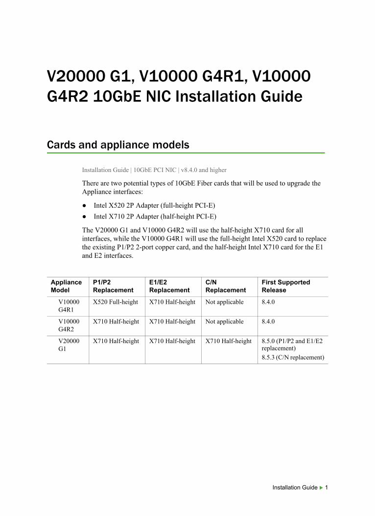
Pulling the appliance from the rack
The V10000 and V20000 Forcepoint Security Appliances are typically mounted in a standard 19” rack.
To remove the appliance from the rack:
1. Power off the appliance and remove the cables from the back of the unit.
2. Flip out the pull tabs on either side of the appliance.
3. Using the tabs, pull the appliance straight out from the rack.
Opening the appliance
To open the V10000 G4R2 or V20000 G1 appliance:
1. Turn the case lock (black screw in the middle of the black tab on the lid) to the open position.
2. Lift the tab all the way up and the cover should slide back.
2 10GbE PCI NIC
V20000 G1, V10000 G4R1, V10000 G4R2 10GbE NIC Installation Guide
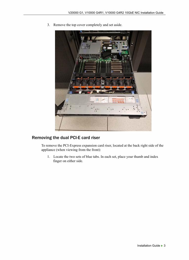
3. Remove the top cover completely and set aside.
Removing the dual PCI-E card riser
To remove the PCI-Express expansion card riser, located at the back right side of the appliance (when viewing from the front):
1. Locate the two sets of blue tabs. In each set, place your thumb and index finger on either side.
Installation Guide 3
V20000 G1, V10000 G4R1, V10000 G4R2 10GbE NIC Installation Guide
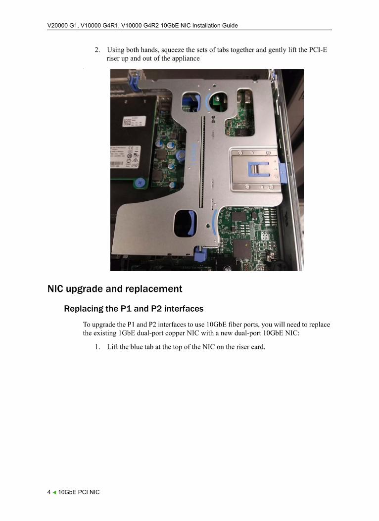
2. Using both hands, squeeze the sets of tabs together and gently lift the PCI-E riser up and out of the appliance
.
NIC upgrade and replacement
Replacing the P1 and P2 interfaces
To upgrade the P1 and P2 interfaces to use 10GbE fiber ports, you will need to replace the existing 1GbE dual-port copper NIC with a new dual-port 10GbE NIC:
1. Lift the blue tab at the top of the NIC on the riser card.
4 10GbE PCI NIC
V20000 G1, V10000 G4R1, V10000 G4R2 10GbE NIC Installation Guide
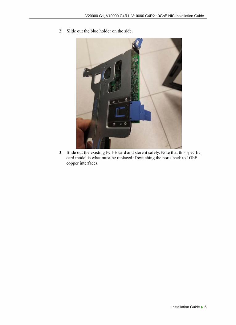
2. Slide out the blue holder on the side.
3. Slide out the existing PCI-E card and store it safely. Note that this specific card model is what must be replaced if switching the ports back to 1GbE copper interfaces.
Installation Guide 5
V20000 G1, V10000 G4R1, V10000 G4R2 10GbE NIC Installation Guide
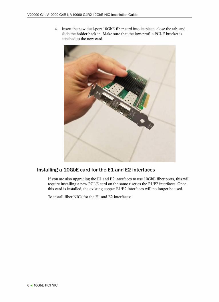
4. Insert the new dual-port 10GbE fiber card into its place, close the tab, and slide the holder back in. Make sure that the low-profile PCI-E bracket is attached to the new card.
Installing a 10GbE card for the E1 and E2 interfaces
If you are also upgrading the E1 and E2 interfaces to use 10GbE fiber ports, this will require installing a new PCI-E card on the same riser as the P1/P2 interfaces. Once this card is installed, the existing copper E1/E2 interfaces will no longer be used.
To install fiber NICs for the E1 and E2 interfaces:
6 10GbE PCI NIC
V20000 G1, V10000 G4R1, V10000 G4R2 10GbE NIC Installation Guide
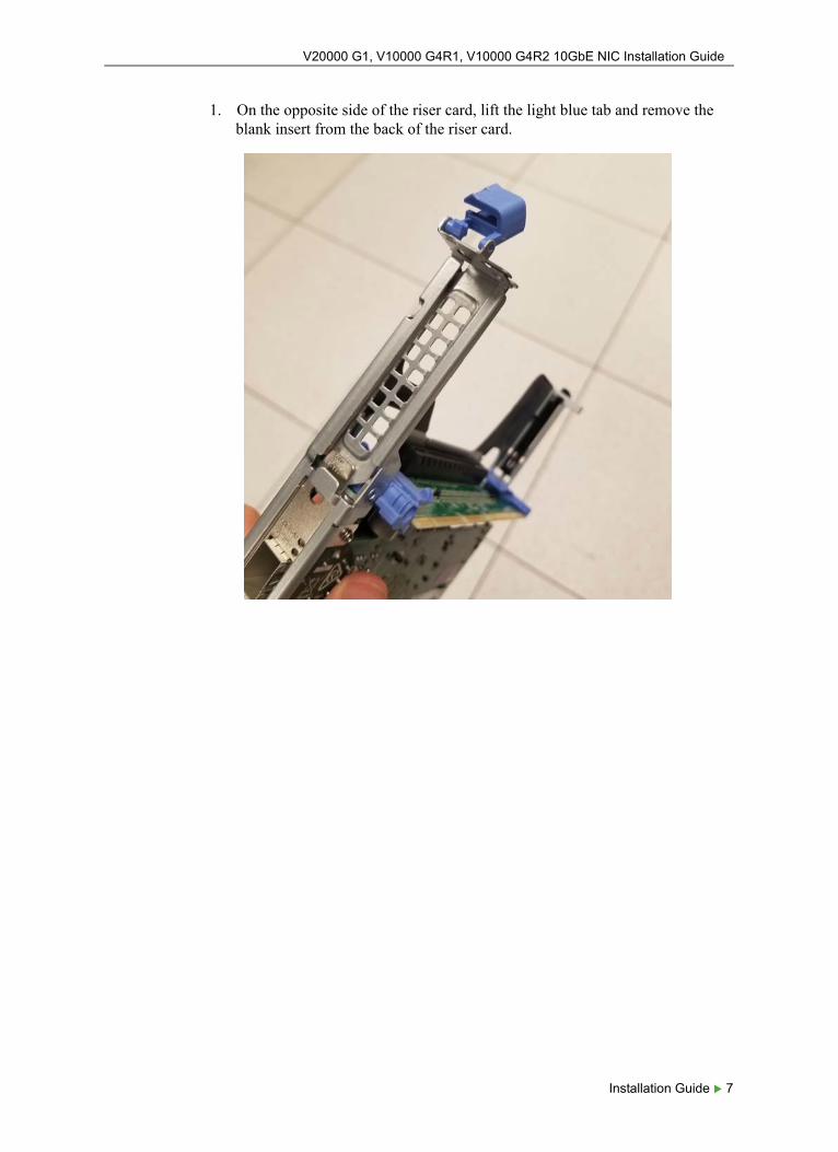
1. On the opposite side of the riser card, lift the light blue tab and remove the blank insert from the back of the riser card.
Installation Guide 7
V20000 G1, V10000 G4R1, V10000 G4R2 10GbE NIC Installation Guide
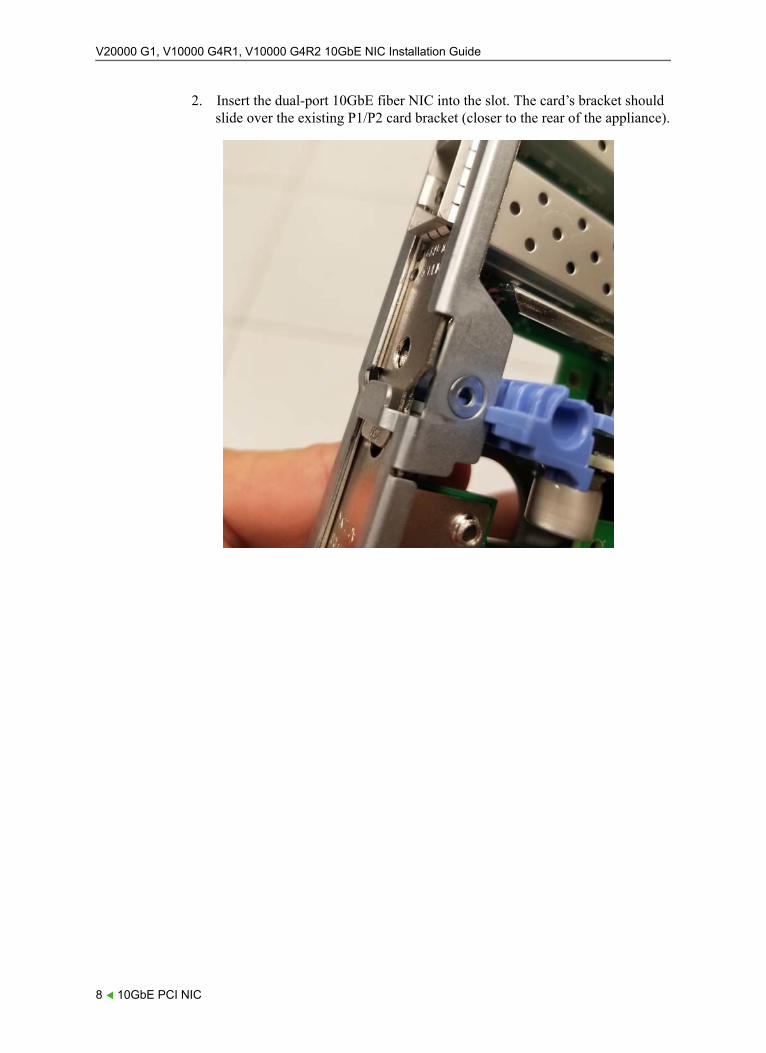
2. Insert the dual-port 10GbE fiber NIC into the slot. The card’s bracket should slide over the existing P1/P2 card bracket (closer to the rear of the appliance).
8 10GbE PCI NIC
V20000 G1, V10000 G4R1, V10000 G4R2 10GbE NIC Installation Guide
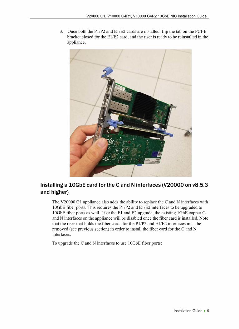
3. Once both the P1/P2 and E1/E2 cards are installed, flip the tab on the PCI-E bracket closed for the E1/E2 card, and the riser is ready to be reinstalled in the appliance.
Installing a 10GbE card for the C and N interfaces (V20000 on v8.5.3 and higher)
The V20000 G1 appliance also adds the ability to replace the C and N interfaces with 10GbE fiber ports. This requires the P1/P2 and E1/E2 interfaces to be upgraded to 10GbE fiber ports as well. Like the E1 and E2 upgrade, the existing 1GbE copper C and N interfaces on the appliance will be disabled once the fiber card is installed. Note that the riser that holds the fiber cards for the P1/P2 and E1/E2 interfaces must be removed (see previous section) in order to install the fiber card for the C and N interfaces.
To upgrade the C and N interfaces to use 10GbE fiber ports:
Installation Guide 9
V20000 G1, V10000 G4R1, V10000 G4R2 10GbE NIC Installation Guide
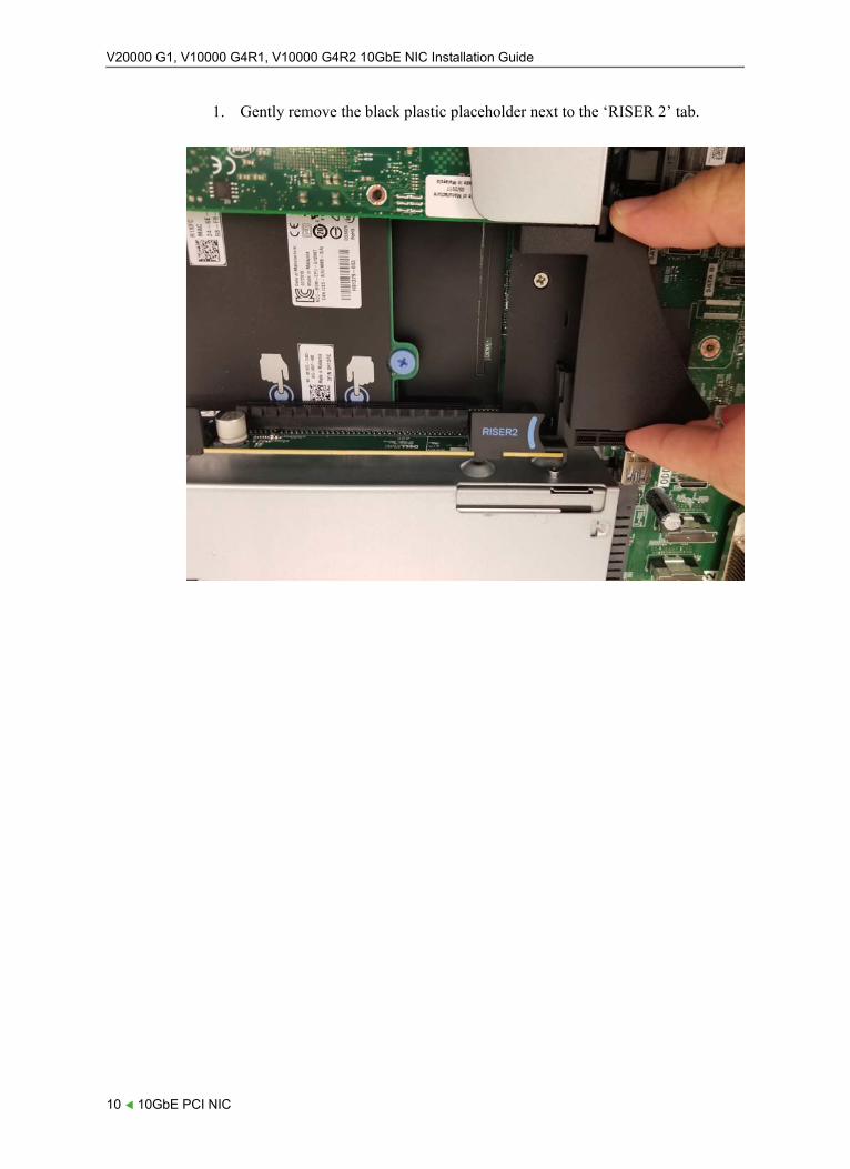
1. Gently remove the black plastic placeholder next to the ‘RISER 2’ tab.
10 10GbE PCI NIC
V20000 G1, V10000 G4R1, V10000 G4R2 10GbE NIC Installation Guide
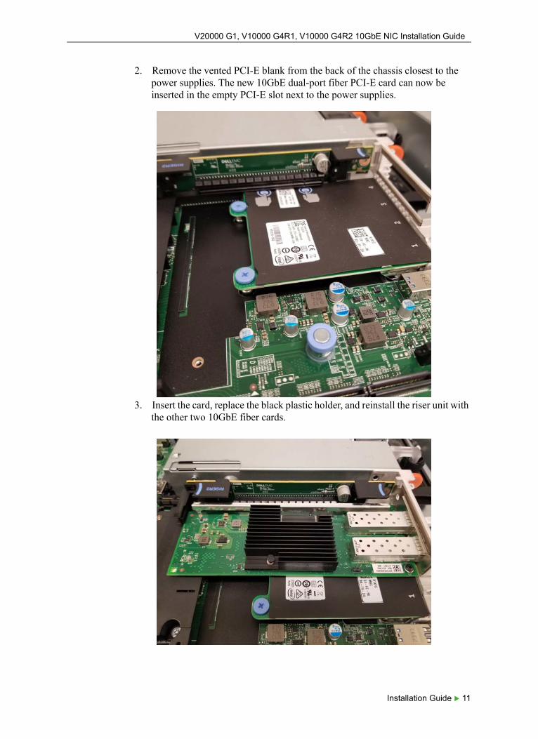
2. Remove the vented PCI-E blank from the back of the chassis closest to the power supplies. The new 10GbE dual-port fiber PCI-E card can now be inserted in the empty PCI-E slot next to the power supplies.
3. Insert the card, replace the black plastic holder, and reinstall the riser unit with the other two 10GbE fiber cards.
Installation Guide 11
V20000 G1, V10000 G4R1, V10000 G4R2 10GbE NIC Installation Guide
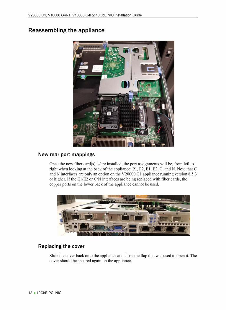
Reassembling the appliance
New rear port mappings
Once the new fiber card(s) is/are installed, the port assignments will be, from left to right when looking at the back of the appliance: P1, P2, E1, E2, C, and N. Note that C and N interfaces are only an option on the V20000 G1 appliance running version 8.5.3 or higher. If the E1/E2 or C/N interfaces are being replaced with fiber cards, the copper ports on the lower back of the appliance cannot be used.
Replacing the cover
Slide the cover back onto the appliance and close the flap that was used to open it. The cover should be secured again on the appliance.
12 10GbE PCI NIC
V20000 G1, V10000 G4R1, V10000 G4R2 10GbE NIC Installation Guide
Rack and cable
Release the catches on the sides of the appliance rails and slide the appliance back into the rack until it locks into place. Reconnect the power cables and connect the network cables. Please note that if the E1 and E2 interfaces are now using fiber, those interfaces will be “upside-down” because that card is inverted.
Installation Guide 13
V20000 G1, V10000 G4R1, V10000 G4R2 10GbE NIC Installation Guide
V10000 G4R1 installation procedure
Installation Guide | 10GbE PCI NIC | v8.4.0 and higher
Opening the appliance
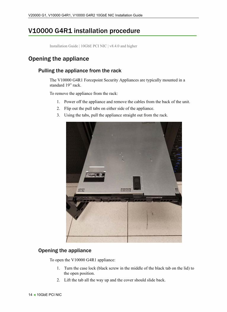
Pulling the appliance from the rack
The V10000 G4R1 Forcepoint Security Appliances are typically mounted in a standard 19” rack.
To remove the appliance from the rack:
1. Power off the appliance and remove the cables from the back of the unit.
2. Flip out the pull tabs on either side of the appliance.
3. Using the tabs, pull the appliance straight out from the rack.
Opening the appliance
To open the V10000 G4R1 appliance:
1. Turn the case lock (black screw in the middle of the black tab on the lid) to the open position.
2. Lift the tab all the way up and the cover should slide back.
14 10GbE PCI NIC
V20000 G1, V10000 G4R1, V10000 G4R2 10GbE NIC Installation Guide
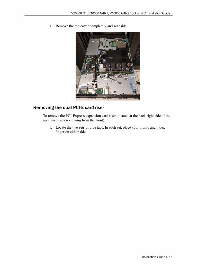
3. Remove the top cover completely and set aside.
Removing the dual PCI-E card riser
To remove the PCI-Express expansion card riser, located at the back right side of the appliance (when viewing from the front):
1. Locate the two sets of blue tabs. In each set, place your thumb and index finger on either side.
Installation Guide 15
V20000 G1, V10000 G4R1, V10000 G4R2 10GbE NIC Installation Guide
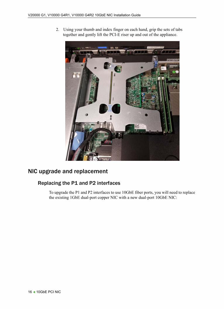
2. Using your thumb and index finger on each hand, grip the sets of tabs together and gently lift the PCI-E riser up and out of the appliance.
NIC upgrade and replacement
Replacing the P1 and P2 interfaces
To upgrade the P1 and P2 interfaces to use 10GbE fiber ports, you will need to replace the existing 1GbE dual-port copper NIC with a new dual-port 10GbE NIC:
16 10GbE PCI NIC
V20000 G1, V10000 G4R1, V10000 G4R2 10GbE NIC Installation Guide
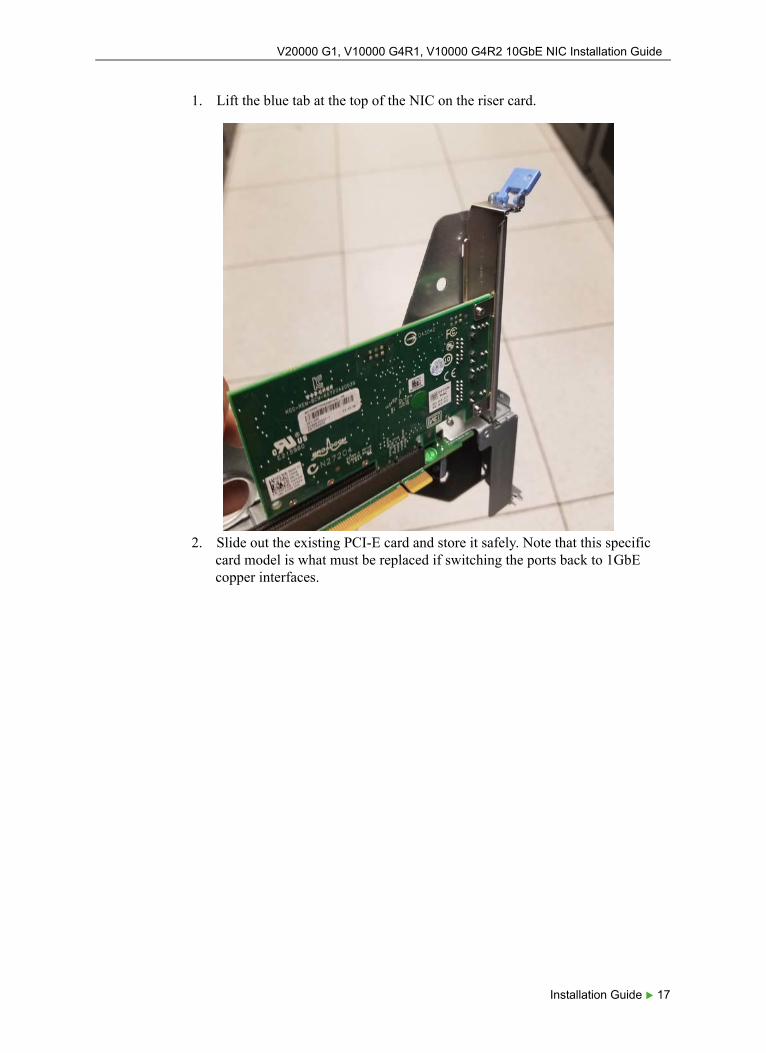
1. Lift the blue tab at the top of the NIC on the riser card.
2. Slide out the existing PCI-E card and store it safely. Note that this specific card model is what must be replaced if switching the ports back to 1GbE copper interfaces.
Installation Guide 17
V20000 G1, V10000 G4R1, V10000 G4R2 10GbE NIC Installation Guide
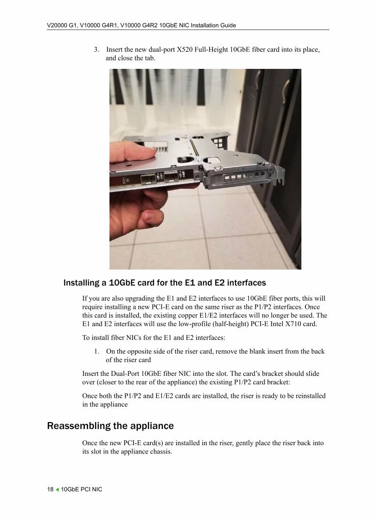
3. Insert the new dual-port X520 Full-Height 10GbE fiber card into its place, and close the tab.
Installing a 10GbE card for the E1 and E2 interfaces
If you are also upgrading the E1 and E2 interfaces to use 10GbE fiber ports, this will require installing a new PCI-E card on the same riser as the P1/P2 interfaces. Once this card is installed, the existing copper E1/E2 interfaces will no longer be used. The E1 and E2 interfaces will use the low-profile (half-height) PCI-E Intel X710 card.
To install fiber NICs for the E1 and E2 interfaces:
1. On the opposite side of the riser card, remove the blank insert from the back of the riser card
Insert the Dual-Port 10GbE fiber NIC into the slot. The card’s bracket should slide over (closer to the rear of the appliance) the existing P1/P2 card bracket:
Once both the P1/P2 and E1/E2 cards are installed, the riser is ready to be reinstalled in the appliance
Reassembling the appliance
Once the new PCI-E card(s) are installed in the riser, gently place the riser back into its slot in the appliance chassis.
18 10GbE PCI NIC
V20000 G1, V10000 G4R1, V10000 G4R2 10GbE NIC Installation Guide
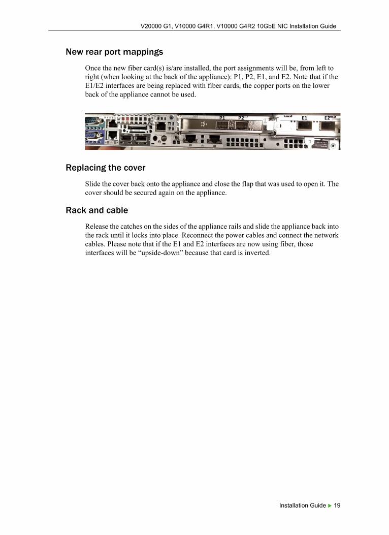
New rear port mappings
Once the new fiber card(s) is/are installed, the port assignments will be, from left to right (when looking at the back of the appliance): P1, P2, E1, and E2. Note that if the E1/E2 interfaces are being replaced with fiber cards, the copper ports on the lower back of the appliance cannot be used.
Replacing the cover
Slide the cover back onto the appliance and close the flap that was used to open it. The cover should be secured again on the appliance.
Rack and cable
Release the catches on the sides of the appliance rails and slide the appliance back into the rack until it locks into place. Reconnect the power cables and connect the network cables. Please note that if the E1 and E2 interfaces are now using fiber, those interfaces will be “upside-down” because that card is inverted.
Installation Guide 19
V20000 G1, V10000 G4R1, V10000 G4R2 10GbE NIC Installation Guide
Post-upgrade steps
Installation Guide | 10GbE PCI NIC | v8.4.0 and higher
Configure network
When the appliance is turned back on, it will automatically detect the new hardware and remap the appliance interfaces to use the new hardware. If the new fiber network uses network settings (IP address, subnet mask, default gateway) that are different from what was configured for the copper networking, be sure to reconfigure the interfaces via the Appliance CLI or Forcepoint Security Appliance Manager (FSAM).
Special Note for V10000 G4R1 appliances in Email Security mode
On V10000 G4R1 appliances with all copper NICs, the E1 and E2 physical interfaces are mapped to the Email Security container on the appliance, and the P1 and P2 ports are only used as secondary interfaces for bonding. However, if the appliance detects one or more 10GbE fiber cards installed, the P1 and P2 interfaces will be mapped to the Email Security container, and the E1 and E2 interfaces will be used as secondary interfaces for bonding only.
Special note for replacing the C interface (V20000 on v8.5.3 or higher)
Please note that Forcepoint Web Security appliances cannot change the C interface IP configuration. If you are planning on upgrading the C interface to use a 10GbE fiber port, one of two things must be done:
● Install the 10GbE fiber NIC for the C interface before running Firstboot, allowing the C interface to be configured with the fiber network, OR
● Ensure that the fiber and copper networks will be identical. For instance, the appliance can connect to the same subnet/default gateway and use the same IP address for both the copper and fiber networks.
If installing the fiber card for the C interface on a Web Security appliance requires a new IP address, subnet, or default gateway, a full appliance re-imaging on version 8.5.3 or higher is required.
20 10GbE PCI NIC

V20000 G1, V10000 G4R1, V10000 G4R2 10GbE NIC Installation Guide
Published 2018
Forcepoint and the FORCEPOINT logo are trademarks of Forcepoint. Raytheon is a registered trademark of Raytheon Company. All other trademarks used in this document are the property of their respective owners.
Installation Guide 21

V20000 G1, V10000 G4R1, V10000 G4R2 10GbE NIC Installation Guide
22 10GbE PCI NIC


![A multi-port 10GbE PCIe NIC featuring UDP offload and ... · de nitively integrated in the high-level trigger of ALICE at LHC [1] while other HEP experiments as ATLAS [2], CMS [3]](https://img.pdfslide.net/doc/110x75/5c6821a409d3f2034d8d0897/a-multi-port-10gbe-pcie-nic-featuring-udp-offload-and-de-nitively-integrated.jpg)