Embed Size (px)
Citation preview

IBM Storwize V7000
Quick Installation GuideVersion 6.1.0
GC27-2290-00
���


IBM Storwize V7000
Quick Installation GuideVersion 6.1.0
GC27-2290-00
���

NoteBefore using this information and the product it supports, read the general information in“Notices” on page 29, the information in the “Safety and environmental notices” on page ix, aswell as the information in the IBM Environmental Notices and User Guide on the documentation CD.
This edition applies to the IBM Storwize V7000 , Version 6.1.0, and to all subsequent releases and modificationsuntil otherwise indicated in new editions.
This edition applies to GC27-2290-00.
© Copyright IBM Corporation 2010.US Government Users Restricted Rights – Use, duplication or disclosure restricted by GSA ADP Schedule Contractwith IBM Corp.

Contents
Figures . . . . . . . . . . . . . . . v
Tables . . . . . . . . . . . . . . . vii
Safety and environmental notices . . . ix
Chapter 1. Before you begin theinstallation . . . . . . . . . . . . . 1Step 1. Reviewing your packing slip . . . . . . 2Step 2. Identifying the hardware components . . . 3Step 3. Verifying environmental requirements . . . 6Step 4. Reviewing enclosure location guidelines . . 7
Chapter 2. Performing the hardwareinstallation . . . . . . . . . . . . . 9Step 5. Installing the support rails . . . . . . . 9Step 6. Installing the enclosures. . . . . . . . 11Step 7. Connecting the SAS cables to the expansionenclosures . . . . . . . . . . . . . . . 13Step 8. Attaching the Ethernet cables . . . . . . 18Step 9. Attaching the longwave SFP transceivers . . 18Step 10. Attaching the Fibre Channel cables. . . . 18Step 11. Connecting the power cords . . . . . . 19Step 12. Powering on the system . . . . . . . 21
Chapter 3. Configuring the system. . . 25Step 13. Configuring the system . . . . . . . 25
Notices . . . . . . . . . . . . . . 29Trademarks . . . . . . . . . . . . . . 31Electronic emission notices . . . . . . . . . 31
Federal Communications Commission (FCC)statement . . . . . . . . . . . . . . 31Industry Canada compliance statement . . . . 32Avis de conformité à la réglementationd'Industrie Canada . . . . . . . . . . . 32Australia and New Zealand Class A Statement 32European Union Electromagnetic CompatibilityDirective . . . . . . . . . . . . . . 32Germany Electromagnetic compatibility directive 32Japan VCCI Council Class A statement . . . . 33People's Republic of China Class A ElectronicEmission Statement . . . . . . . . . . . 33International Electrotechnical Commission (IEC)statement . . . . . . . . . . . . . . 34United Kingdom telecommunicationsrequirements . . . . . . . . . . . . . 34Korean Communications Commission (KCC)Class A Statement . . . . . . . . . . . 34Russia Electromagnetic Interference (EMI) ClassA Statement . . . . . . . . . . . . . 34Taiwan Class A compliance statement . . . . 34
European Contact Information . . . . . . . . 34Taiwan Contact Information . . . . . . . . . 35
© Copyright IBM Corp. 2010 iii

iv Storwize V7000 Version 6.1.0: Quick Installation Guide
Figures
1. 24 drives and two end caps . . . . . . . 32. 12 drives and two end caps . . . . . . . 33. Rear view of a control enclosure . . . . . . 44. Data ports and LEDs in the rear of the control
enclosure. . . . . . . . . . . . . . 45. Rear view of an expansion enclosure . . . . 56. SAS ports and LEDs in rear of expansion
enclosure. . . . . . . . . . . . . . 67. Hole locations in the front of the rack . . . . 98. Attaching a rail assembly to a rack cabinet 109. Hole locations in the back of the rack . . . . 10
10. Removing the enclosure end cap . . . . . 1211. Securing an enclosure to a rack cabinet 13
12. Attaching an expansion enclosure to thecontrol enclosure . . . . . . . . . . . 15
13. Adding a second expansion enclosure. . . . 1614. Attaching SAS cables to the enclosures 1715. Unlocking the cable retention bracket . . . . 2016. Sliding the cable retention bracket directly
behind the power cord . . . . . . . . . 2117. LEDs on the power supply units of the
expansion enclosure. . . . . . . . . . 2218. LEDs on the power supply units of the control
enclosure . . . . . . . . . . . . . 2319. Initialization tool welcome panel . . . . . 26
© Copyright IBM Corp. 2010 v

vi Storwize V7000 Version 6.1.0: Quick Installation Guide
Tables
1. Cabling guide . . . . . . . . . . . . 142. LED status when expansion enclosures are
powered on . . . . . . . . . . . . 22
3. LED status when control enclosure is poweredon. . . . . . . . . . . . . . . . 23
© Copyright IBM Corp. 2010 vii

viii Storwize V7000 Version 6.1.0: Quick Installation Guide

Safety and environmental notices
Review the multilingual safety notices for the IBM® Storwize® V7000 system before you install and usethe product.
Suitability for telecommunication environment: This product is not intended to connect directly orindirectly by any means whatsoever to interfaces of public telecommunications networks.
To find the translated text for a caution or danger notice:1. Look for the identification number at the end of each caution notice or each danger notice. In the
following examples, the numbers (C001) and (D002) are the identification numbers.CAUTION:A caution notice indicates the presence of a hazard that has the potential of causing moderate orminor personal injury. (C001)
DANGER
A danger notice indicates the presence of a hazard that has the potential of causing death orserious personal injury. (D002)
2. Locate IBM Systems Safety Notices with the user publications that were provided with the StorwizeV7000 hardware.
3. Find the matching identification number in the IBM Systems Safety Notices. Then review the topicsconcerning the safety notices to ensure that you are in compliance.
4. Optionally, read the multilingual safety instructions on the Storwize V7000 website. Go to Support forStorwize V7000 website at www.ibm.com/storage/support/storwize/v7000, click the current productdocumentation link, and then click Multi-language.
© Copyright IBM Corp. 2010 ix

x Storwize V7000 Version 6.1.0: Quick Installation Guide

Chapter 1. Before you begin the installation
The Quick Installation Guide contains a set of instructions to help you unpack your shipping order andinstall your system. The guide is divided into three chapters. The steps in the first chapter involveverifying your order, becoming familiar with the hardware component terminology, and ensuring thatyou have met the environmental requirements. The steps in the second chapter involve installing thehardware and attaching the data cables and power cords. The final chapter helps you create yourconfiguration file and access the management GUI. The management GUI guides you through the initialconfiguration process.
See the following website for the available translated versions of the Quick Installation Guide:
Support for Storwize V7000 website at www.ibm.com/storage/support/storwize/v7000
Occasionally you are referred to topics in the Storwize V7000 Information Center. A copy of the StorwizeV7000 Information Center is on the DVD that is included in your shipping order.
Note: The guide assumes that you have read the planning information regarding your physicalenvironment that is available from the Storwize V7000 Information Center.
Depending on your order, this documentation steps you through setting up yoursystem for the following scenariosv Setting up a new system that consists of installing a control enclosure only. In this case, you are not
installing any expansion enclosures.v Setting up a new system that consists of installing a control enclosure and installing one or more
expansion enclosures.v Adding an expansion enclosure to an existing system. In this case, you initially installed a control
enclosure or installed a control enclosure and one or more expansion enclosures. You want to add anexpansion enclosure to your existing system.
Be familiar with the following informationv Where it is applicable, a CAUTION notice indicates situations that can be potentially hazardous to you.
Before doing a step that contains a caution notice, read and understand the statement that accompaniesit.
v Use safe practices when lifting. The fully populated enclosure weighs about 57.2 lbs (26 kg). At leasttwo people are required to lift and install the enclosure into the rack or to remove an enclosure fromthe rack.
© Copyright IBM Corp. 2010 1
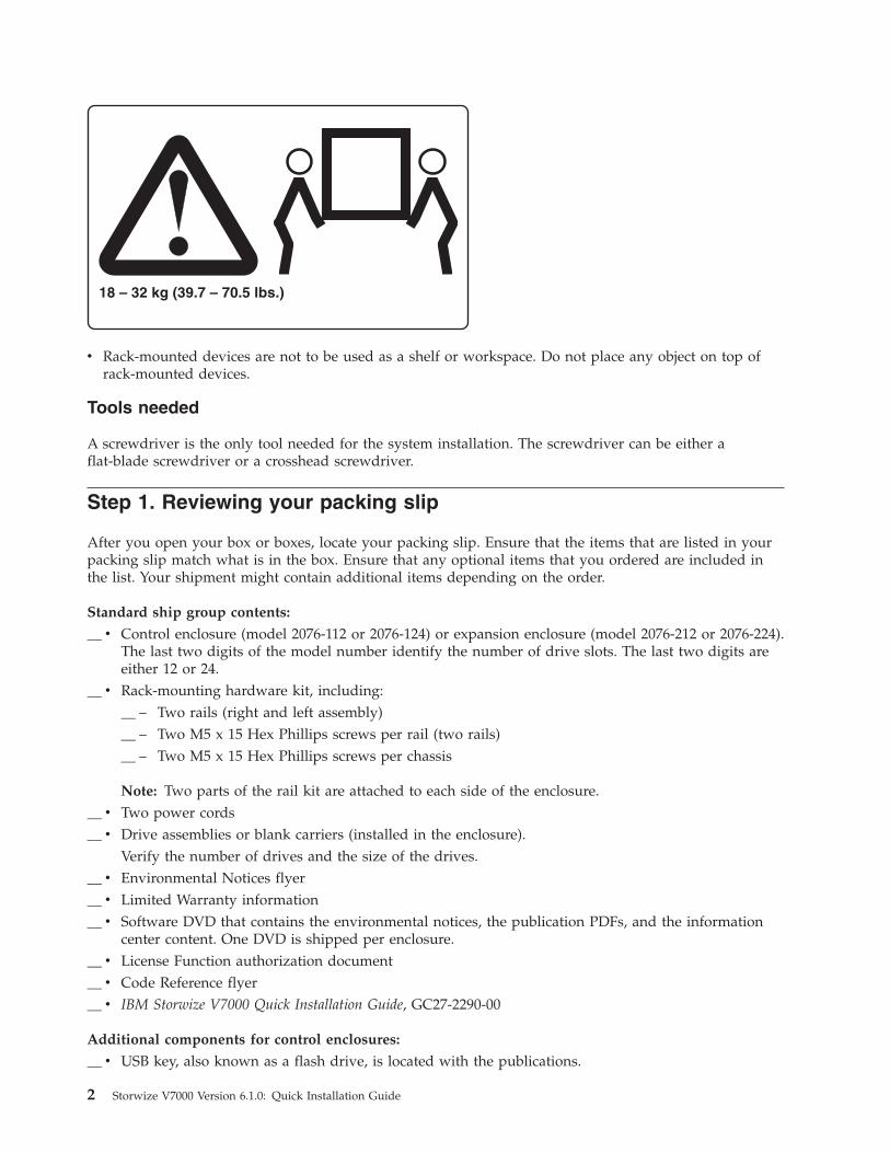
v Rack-mounted devices are not to be used as a shelf or workspace. Do not place any object on top ofrack-mounted devices.
Tools needed
A screwdriver is the only tool needed for the system installation. The screwdriver can be either aflat-blade screwdriver or a crosshead screwdriver.
Step 1. Reviewing your packing slip
After you open your box or boxes, locate your packing slip. Ensure that the items that are listed in yourpacking slip match what is in the box. Ensure that any optional items that you ordered are included inthe list. Your shipment might contain additional items depending on the order.
Standard ship group contents:
__ v Control enclosure (model 2076-112 or 2076-124) or expansion enclosure (model 2076-212 or 2076-224).The last two digits of the model number identify the number of drive slots. The last two digits areeither 12 or 24.
__ v Rack-mounting hardware kit, including:__ – Two rails (right and left assembly)__ – Two M5 x 15 Hex Phillips screws per rail (two rails)__ – Two M5 x 15 Hex Phillips screws per chassis
Note: Two parts of the rail kit are attached to each side of the enclosure.__ v Two power cords__ v Drive assemblies or blank carriers (installed in the enclosure).
Verify the number of drives and the size of the drives.__ v Environmental Notices flyer__ v Limited Warranty information__ v Software DVD that contains the environmental notices, the publication PDFs, and the information
center content. One DVD is shipped per enclosure.__ v License Function authorization document__ v Code Reference flyer__ v IBM Storwize V7000 Quick Installation Guide, GC27-2290-00
Additional components for control enclosures:
__ v USB key, also known as a flash drive, is located with the publications.
2 Storwize V7000 Version 6.1.0: Quick Installation Guide
__ v Fibre Channel cables, if ordered__ v Small form-factor pluggable (SFP) transceivers that are preinstalled in the enclosure__ v Longwave SFP transceivers, if ordered
Additional components for expansion enclosures:
__ v Two SAS cables for each expansion enclosure
Step 2. Identifying the hardware components
The following graphics and descriptions identify the various hardware components and port locations forthe control enclosure and the expansion enclosure. Each enclosure contains two canisters, two powersupply units, drives, and a chassis. The power supply units for the control enclosure each contain abattery. Each enclosure takes up the full 2U height in the rack.
See the IBM Storwize V7000 Troubleshooting, Recovery, and Maintenance Guide PDF on the DVD for the fulldescriptions of the hardware components.
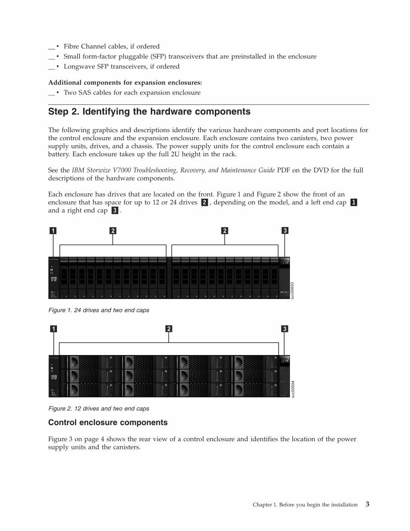
Each enclosure has drives that are located on the front. Figure 1 and Figure 2 show the front of anenclosure that has space for up to 12 or 24 drives �2�, depending on the model, and a left end cap �1�and a right end cap �3�.
Control enclosure components
Figure 3 on page 4 shows the rear view of a control enclosure and identifies the location of the powersupply units and the canisters.
svc00693
1 2 2 3
Figure 1. 24 drives and two end caps
svc00694
1 2 3
Figure 2. 12 drives and two end caps
Chapter 1. Before you begin the installation 3
v Power supply units are located on the left and right of the canisters. Each unit contains a battery.Power supply 1 �1� is located on the left. Power supply 2 �2� is located on the right. Power supply 1is inserted top side up, and power supply 2 is inverted, or top side down.
Important: The power supply units for the control enclosure and expansion enclosure are notinterchangeable.
v Two canisters are housed in the middle of the enclosure. Each canister is known as a node canister. Theupper canister is canister 1 �3�, and the lower canister is canister 2 �4�. Canister 1 is top side up, andcanister 2 is inverted, or top side down.
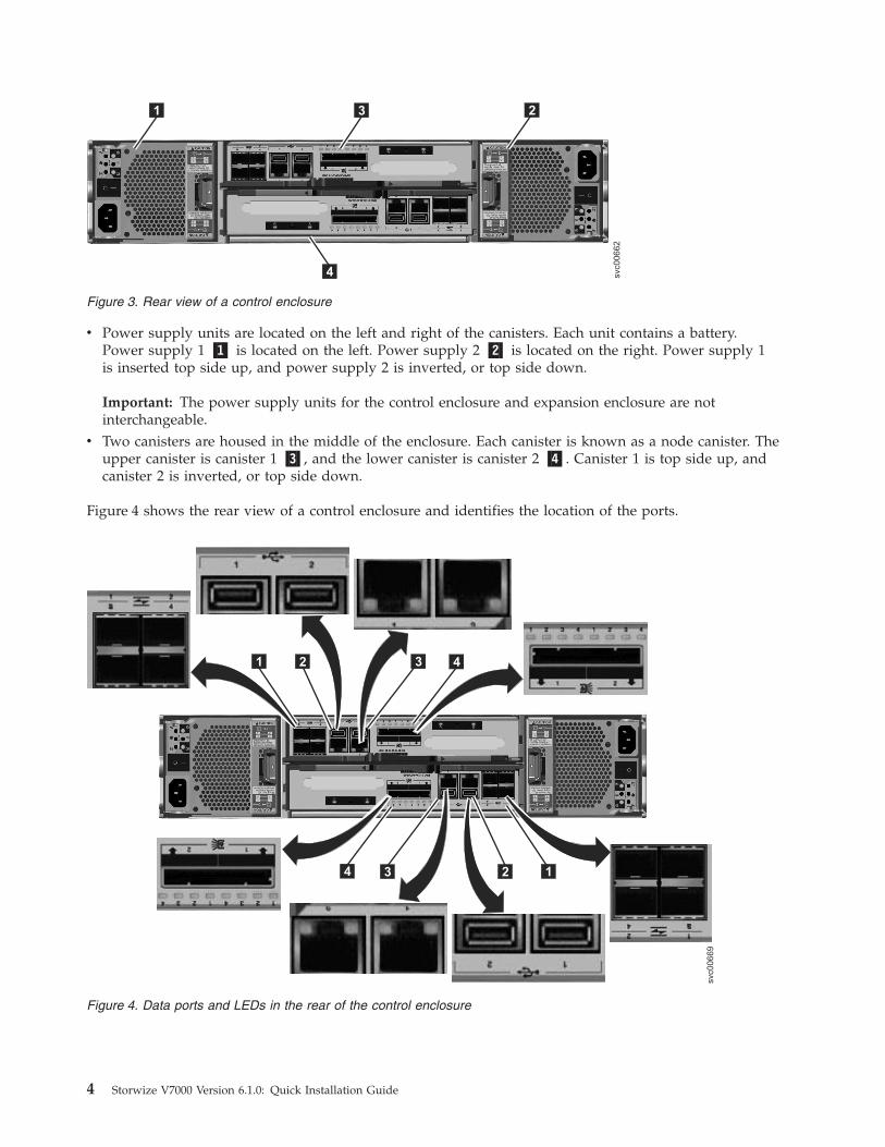
Figure 4 shows the rear view of a control enclosure and identifies the location of the ports.
1 23
svc00662
4
Figure 3. Rear view of a control enclosure
svc00669
1 42 3
14 23
Figure 4. Data ports and LEDs in the rear of the control enclosure
4 Storwize V7000 Version 6.1.0: Quick Installation Guide
v �1� Fibre Channel ports. Each canister has four Fibre Channel ports. They are in a block of four in tworows of two connectors. The ports are numbered 1 - 4 from left to right, top to bottom. Their use isoptional.
v �2� USB ports. Each canister has two USB ports. The ports are side by side on the canister and arenumbered 1 on the left and 2 on the right. One port is used during installation.
v �3� Ethernet ports. Each canister has two Ethernet ports. The ports are side by side on the canister.They are numbered 1 on the left and 2 on the right. Port 1 must be connected; the use of port 2 isoptional.
v �4� Serial-attached SCSI (SAS) ports. Each canister has two SAS ports. The ports are side by side on thecanister. They are numbered 1 on the left and 2 on the right. Port 1 must be connected if you areadding one expansion enclosure. Port 2 must be connected if you are adding a second expansionenclosure.
Note: The reference to the left and right locations applies to canister 1, which is the upper canister. Theport locations are inverted for canister 2, which is the lower canister.
Expansion enclosure components
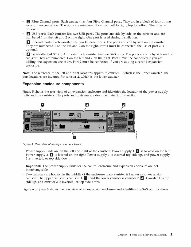
Figure 5 shows the rear view of an expansion enclosure and identifies the location of the power supplyunits and the canisters. The ports and their use are described later in this section.
v Power supply units are on the left and right of the canisters. Power supply 1 �1� is located on the left.Power supply 2 �2� is located on the right. Power supply 1 is inserted top side up, and power supply2 is inverted, or top side down.
Important: The power supply units for the control enclosure and expansion enclosure are notinterchangeable.
v Two canisters are housed in the middle of the enclosure. Each canister is known as an expansioncanister. The upper canister is canister 1 �3�, and the lower canister is canister 2 �4�. Canister 1 is topside up, and canister 2 is inverted, or top side down.
Figure 6 on page 6 shows the rear view of an expansion enclosure and identifies the SAS port locations.
1 23
svc00610
4
Figure 5. Rear view of an expansion enclosure
Chapter 1. Before you begin the installation 5
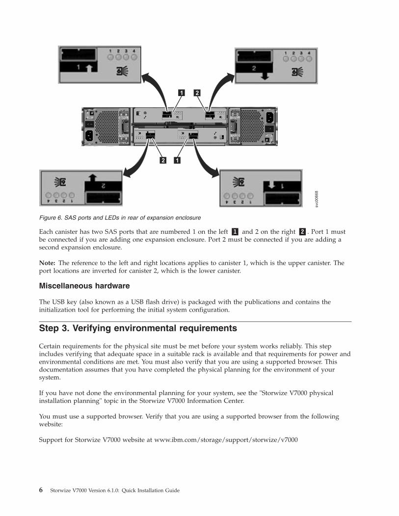
Each canister has two SAS ports that are numbered 1 on the left �1� and 2 on the right �2�. Port 1 mustbe connected if you are adding one expansion enclosure. Port 2 must be connected if you are adding asecond expansion enclosure.
Note: The reference to the left and right locations applies to canister 1, which is the upper canister. Theport locations are inverted for canister 2, which is the lower canister.
Miscellaneous hardware
The USB key (also known as a USB flash drive) is packaged with the publications and contains theinitialization tool for performing the initial system configuration.
Step 3. Verifying environmental requirements
Certain requirements for the physical site must be met before your system works reliably. This stepincludes verifying that adequate space in a suitable rack is available and that requirements for power andenvironmental conditions are met. You must also verify that you are using a supported browser. Thisdocumentation assumes that you have completed the physical planning for the environment of yoursystem.
If you have not done the environmental planning for your system, see the "Storwize V7000 physicalinstallation planning" topic in the Storwize V7000 Information Center.
You must use a supported browser. Verify that you are using a supported browser from the followingwebsite:
Support for Storwize V7000 website at www.ibm.com/storage/support/storwize/v7000
svc00668
1
12
2
Figure 6. SAS ports and LEDs in rear of expansion enclosure
6 Storwize V7000 Version 6.1.0: Quick Installation Guide
Step 4. Reviewing enclosure location guidelines
Use these guidelines to create a plan that identifies an appropriate location in the rack for the enclosureor enclosures that you are installing now or in the future. An enclosure requires two standard rack unitsof space in a rack. See Figure 9 on page 10 for a sample template of two rack units. For example, positionthe control enclosure in the middle of the rack beginning at rack numbers 18 and 19.
If you are installing a control enclosure only, follow these guidelines:
Position the enclosure in the rack so that you can easily view it and access it for servicing. This actionhelps the rack to remain stable and provides a way for two or more people to install and remove theenclosure.
Note: If you plan to add expansion enclosures in the future, review the guidelines for "If you areinstalling an expansion enclosure only."
If you are installing a control enclosure plus one or more expansion enclosures, follow theseguidelines:
If you have one or more expansion enclosures, position the control enclosure in the center of the rack.Balance the expansion enclosures above and below the control enclosure.
For example, position the control enclosure in the middle of the rack for ease of cabling.v You can have no more than five expansion enclosures attached to SAS port 1 of the control enclosure.v You can have no more than four expansion enclosures attached to SAS port 2 of the control enclosure.v Position the enclosures together; avoid adding other equipment between enclosures.v When you add the first expansion enclosure to a control enclosure, it is preferable to add the enclosure
directly below the control enclosure.v When you add a second expansion enclosure, it is preferable to add the enclosure directly above the
control enclosure. For each additional expansion enclosure that you add, alternately add it below orabove the control enclosure.
v Position the enclosures in the rack so that you can easily view them and access them for servicing. Thisaction helps the rack to remain stable and provides a way for two or more people to install andremove the enclosures.
If you are installing an expansion enclosure only, follow these guidelines:
When you add the first expansion enclosure to a control enclosure, it is preferable to add the enclosuredirectly below the control enclosure. When you add a second expansion enclosure, it is preferable to addthe enclosure directly above the control enclosure. For each expansion enclosure that you add, alternatelyadd it below or above the control enclosure.
Chapter 1. Before you begin the installation 7

8 Storwize V7000 Version 6.1.0: Quick Installation Guide
Chapter 2. Performing the hardware installation
You have completed the initial steps of verifying the shipping contents and becoming familiar with thehardware components. You have verified that the power and environmental requirements are met andhave planned the location of the enclosures. You are now ready to begin installing the hardwarecomponents and connecting the data cables and power cords.
Step 5. Installing the support rails
To install the support rails, perform the following steps:1. Locate the rack mounting rails and screws.
The rail assembly is made up of two sets of rails. One set of rails is already installed, or preinstalled,on the sides of the enclosures. The other set of rails must be installed in the rack cabinet. The railson the sides of the enclosures slide into the rails that are installed in the rack cabinet.
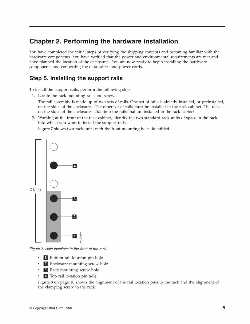
2. Working at the front of the rack cabinet, identify the two standard rack units of space in the rackinto which you want to install the support rails.Figure 7 shows two rack units with the front mounting holes identified.
v �1� Bottom rail location pin holev �2� Enclosure mounting screw holev �3� Rack mounting screw holev �4� Top rail location pin holeFigure 8 on page 10 shows the alignment of the rail location pins to the rack and the alignment ofthe clamping screw to the rack.
2 Units
1
2
3
4
svc00695
Figure 7. Hole locations in the front of the rack
© Copyright IBM Corp. 2010 9
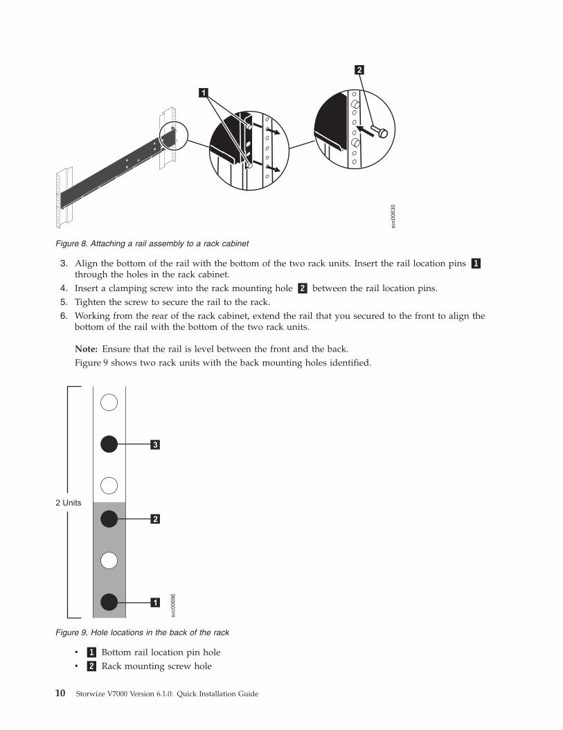
3. Align the bottom of the rail with the bottom of the two rack units. Insert the rail location pins �1�through the holes in the rack cabinet.
4. Insert a clamping screw into the rack mounting hole �2� between the rail location pins.5. Tighten the screw to secure the rail to the rack.6. Working from the rear of the rack cabinet, extend the rail that you secured to the front to align the
bottom of the rail with the bottom of the two rack units.
Note: Ensure that the rail is level between the front and the back.Figure 9 shows two rack units with the back mounting holes identified.
v �1� Bottom rail location pin holev �2� Rack mounting screw hole
1
2
svc00630
Figure 8. Attaching a rail assembly to a rack cabinet
svc00696
2 Units
1
2
3
Figure 9. Hole locations in the back of the rack
10 Storwize V7000 Version 6.1.0: Quick Installation Guide
v �3� Top rail location pin hole7. Insert the rail location pins through the holes in the rack cabinet.8. Insert a clamping screw into the rack mounting hole between the rail location pins.9. Tighten the screw to secure the rail to the rack from the back side.
10. Repeat the steps to secure the opposite rail to the rack cabinet.11. Repeat the procedure for each additional enclosure.
Step 6. Installing the enclosures
CAUTION:
1. To lift and install the enclosure into the rack requires at least two people.
2. Load the rack from the bottom to ensure rack stability. Empty the rack from the top down.
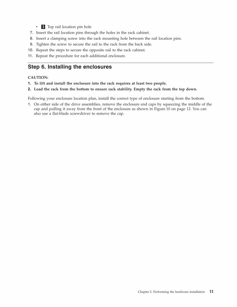
Following your enclosure location plan, install the correct type of enclosure starting from the bottom.1. On either side of the drive assemblies, remove the enclosure end caps by squeezing the middle of the
cap and pulling it away from the front of the enclosure as shown in Figure 10 on page 12. You canalso use a flat-blade screwdriver to remove the cap.
Chapter 2. Performing the hardware installation 11
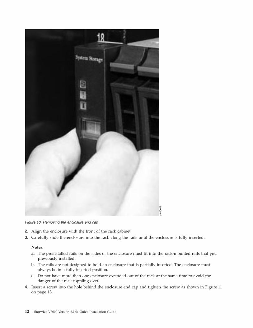
2. Align the enclosure with the front of the rack cabinet.3. Carefully slide the enclosure into the rack along the rails until the enclosure is fully inserted.
Notes:
a. The preinstalled rails on the sides of the enclosure must fit into the rack-mounted rails that youpreviously installed.
b. The rails are not designed to hold an enclosure that is partially inserted. The enclosure mustalways be in a fully inserted position.
c. Do not have more than one enclosure extended out of the rack at the same time to avoid thedanger of the rack toppling over.
4. Insert a screw into the hole behind the enclosure end cap and tighten the screw as shown in Figure 11on page 13.
svc00648
Figure 10. Removing the enclosure end cap
12 Storwize V7000 Version 6.1.0: Quick Installation Guide
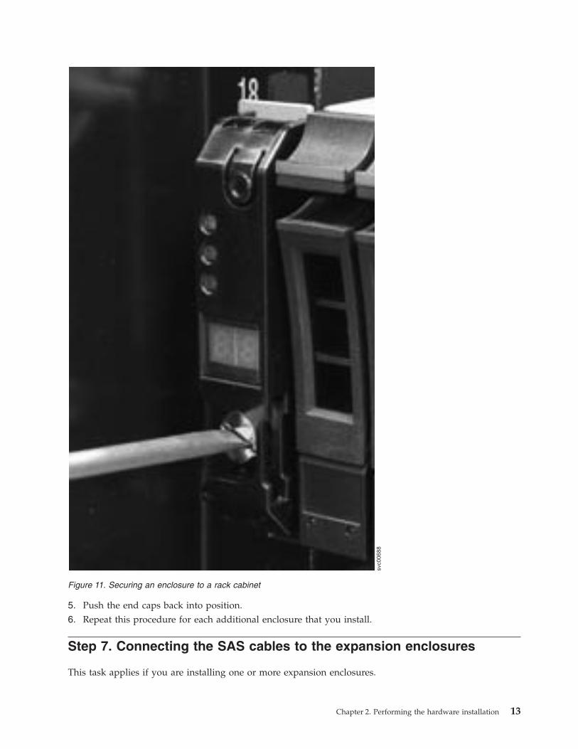
5. Push the end caps back into position.6. Repeat this procedure for each additional enclosure that you install.
Step 7. Connecting the SAS cables to the expansion enclosures
This task applies if you are installing one or more expansion enclosures.
svc00688
Figure 11. Securing an enclosure to a rack cabinet
Chapter 2. Performing the hardware installation 13
Note: The enclosure terminology that is used in this topic is described fully in “Step 2. Identifying thehardware components” on page 3.
Be aware of these guidelines when you begin to attach the cables to the SAS ports:v No more than five expansion enclosures can be chained to port 1 (below the control enclosure). The
connecting sequence from port 1 of the node canister is called chain 1.v No more than four expansion enclosures can be chained to port 2 (above the control enclosure). The
connecting sequence from port 2 of the node canister is called chain 2.v No cable can be connected between a port on an upper canister and a port on a lower canister.v Attach cables serially between enclosures; do not skip an enclosure.v The last enclosure in a chain must not have cables in port 2 of canister 1 and port 2 of canister 2.v Ensure that cables are installed in a tidy manner to reduce the risk of cable damage when Storwize
V7000 replaceable units are removed or inserted.v Arrange your cables to provide access to:
– The USB ports. Access is required to this port when you use the USB key to configure the system.– The enclosures themselves. Access is required to the hardware for servicing and for safely removing
and replacing components using two or more people.v Ensure that each SAS cable is fully inserted. A click is heard when the cable is successfully inserted.
Note: If you make a mistake during cabling and must unplug a SAS cable, pull the blue tag to releasethe cable.
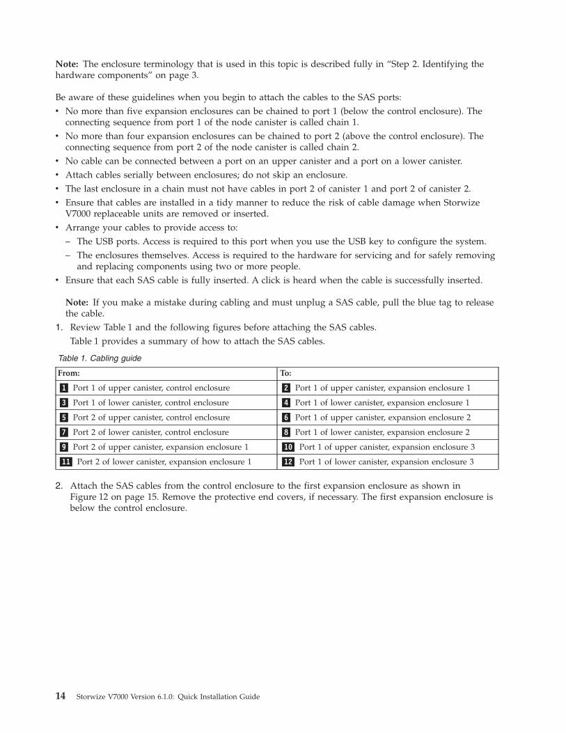
1. Review Table 1 and the following figures before attaching the SAS cables.Table 1 provides a summary of how to attach the SAS cables.
Table 1. Cabling guide
From: To:
�1� Port 1 of upper canister, control enclosure �2� Port 1 of upper canister, expansion enclosure 1
�3� Port 1 of lower canister, control enclosure �4� Port 1 of lower canister, expansion enclosure 1
�5� Port 2 of upper canister, control enclosure �6� Port 1 of upper canister, expansion enclosure 2
�7� Port 2 of lower canister, control enclosure �8� Port 1 of lower canister, expansion enclosure 2
�9� Port 2 of upper canister, expansion enclosure 1 �10� Port 1 of upper canister, expansion enclosure 3
�11� Port 2 of lower canister, expansion enclosure 1 �12� Port 1 of lower canister, expansion enclosure 3
2. Attach the SAS cables from the control enclosure to the first expansion enclosure as shown inFigure 12 on page 15. Remove the protective end covers, if necessary. The first expansion enclosure isbelow the control enclosure.
14 Storwize V7000 Version 6.1.0: Quick Installation Guide
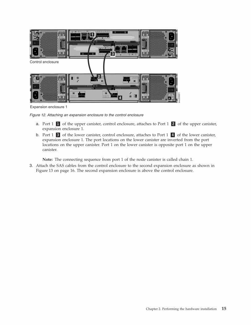
a. Port 1 �1� of the upper canister, control enclosure, attaches to Port 1 �2� of the upper canister,expansion enclosure 1.
b. Port 1 �3� of the lower canister, control enclosure, attaches to Port 1 �4� of the lower canister,expansion enclosure 1. The port locations on the lower canister are inverted from the portlocations on the upper canister. Port 1 on the lower canister is opposite port 1 on the uppercanister.
Note: The connecting sequence from port 1 of the node canister is called chain 1.3. Attach the SAS cables from the control enclosure to the second expansion enclosure as shown in
Figure 13 on page 16. The second expansion enclosure is above the control enclosure.
Control enclosure
Expansion enclosure 1
2
4
svc00661
1
3
Figure 12. Attaching an expansion enclosure to the control enclosure
Chapter 2. Performing the hardware installation 15
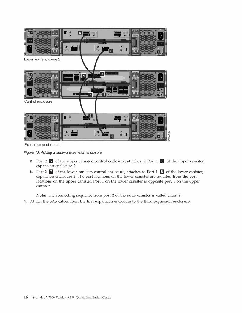
a. Port 2 �5� of the upper canister, control enclosure, attaches to Port 1 �6� of the upper canister,expansion enclosure 2.
b. Port 2 �7� of the lower canister, control enclosure, attaches to Port 1 �8� of the lower canister,expansion enclosure 2. The port locations on the lower canister are inverted from the portlocations on the upper canister. Port 1 on the lower canister is opposite port 1 on the uppercanister.
Note: The connecting sequence from port 2 of the node canister is called chain 2.4. Attach the SAS cables from the first expansion enclosure to the third expansion enclosure.
Control enclosure
Expansion enclosure 1
2
Expansion enclosure 2
6
8
4
svc00660
15
37
Figure 13. Adding a second expansion enclosure
16 Storwize V7000 Version 6.1.0: Quick Installation Guide
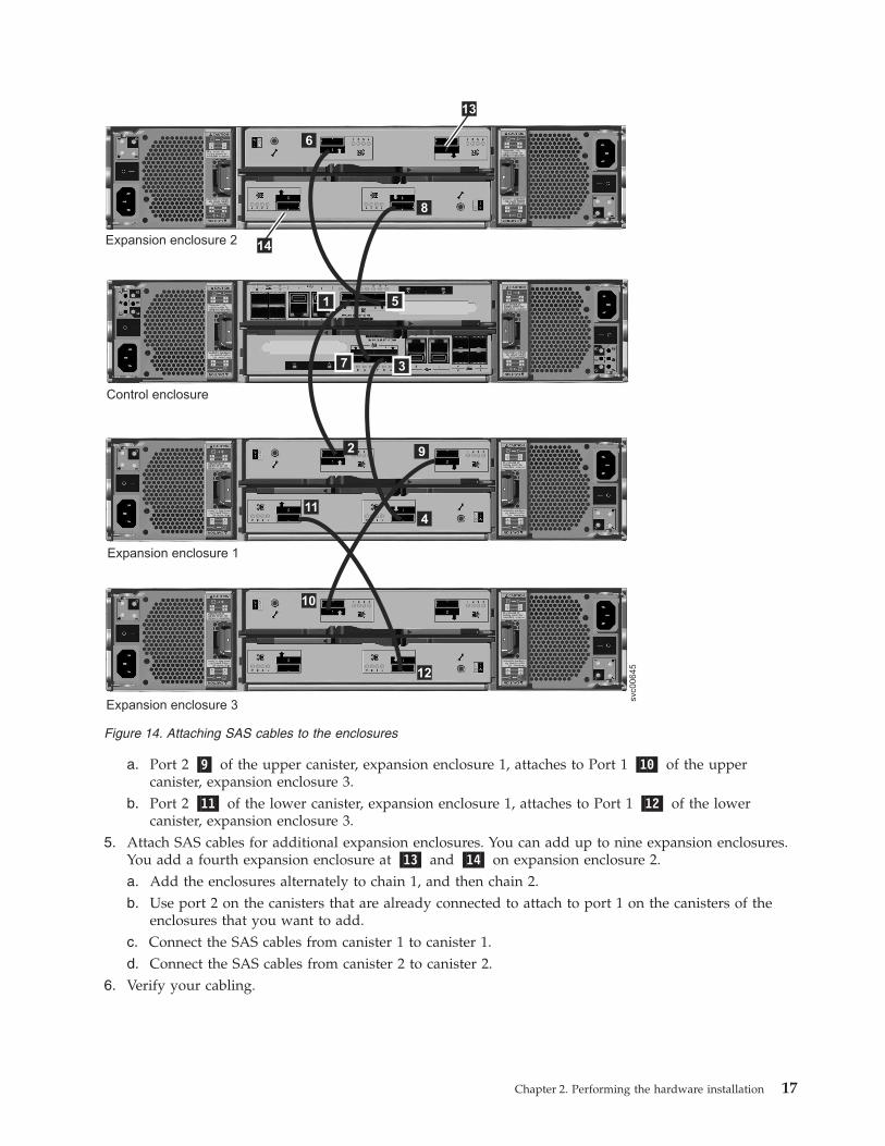
a. Port 2 �9� of the upper canister, expansion enclosure 1, attaches to Port 1 �10� of the uppercanister, expansion enclosure 3.
b. Port 2 �11� of the lower canister, expansion enclosure 1, attaches to Port 1 �12� of the lowercanister, expansion enclosure 3.
5. Attach SAS cables for additional expansion enclosures. You can add up to nine expansion enclosures.You add a fourth expansion enclosure at �13� and �14� on expansion enclosure 2.a. Add the enclosures alternately to chain 1, and then chain 2.b. Use port 2 on the canisters that are already connected to attach to port 1 on the canisters of the
enclosures that you want to add.c. Connect the SAS cables from canister 1 to canister 1.d. Connect the SAS cables from canister 2 to canister 2.
6. Verify your cabling.
Control enclosure
Expansion enclosure 1
2
Expansion enclosure 3
Expansion enclosure 214
6
13
8
9
411
10
12
svc00645
1 5
7 3
Figure 14. Attaching SAS cables to the enclosures
Chapter 2. Performing the hardware installation 17
Step 8. Attaching the Ethernet cables
This task applies if you are installing a control enclosure only or a control enclosure plus one or moreexpansion enclosures.
This task assumes that your initial planning has determined where the Ethernet cables are to be located.
Attention: The IP address 192.168.70.121 is preconfigured as the service address on Ethernet port 1 oncanister 1. The IP address 192.168.70.122 is preconfigured as the service address on Ethernet port 1 ofcanister 2. Do not attach Ethernet cables to the network if a conflict exists with these IP addresses. Ifthese IP addresses conflict with any devices in your network, use the Set or reset service IP addressoption of the initialization tool that is described in step “Step 13. Configuring the system” on page 25 toset the service IP addresses on any node that has a conflict before continuing. If necessary, perform theprocedure on both nodes. See the IBM Storwize V7000 Troubleshooting, Recovery, and Maintenance Guide PDFon the DVD for further information about setting service IP addresses using a USB key.1. For each node canister in the control enclosure, connect an Ethernet cable between Ethernet port 1 of
the canister and an enabled port on your Ethernet switch or router. Port 1 can be used formanagement, service, and iSCSI.
Note: Ethernet cables are not supplied as part of your order. A CAT 5 unshielded twisted pair (UTP)is the minimum requirement for an Ethernet cable.Ensure that cables are installed in a tidy manner to reduce the risk of cable damage when StorwizeV7000 replaceable units are removed or inserted.
2. Optionally attach Ethernet cables between Ethernet port 2 on each node canister and your Ethernetnetwork. Port 2 can be used for management and iSCSI.
Step 9. Attaching the longwave SFP transceivers
This task applies if you are using longwave SFP transceivers and have ordered longwave SFPtransceivers.
Attention: The shortwave SFP transceivers are preinstalled in the control enclosure. No further action isrequired if you are using the shortwave SFP transceivers.1. For both node canisters in the control enclosure, identify which of the four shortwave SFP transceivers
must be replaced with longwave SFP transceivers.2. Remove the shortwave SFP transceivers.3. Plug the longwave SFP transceivers into ports 1-4, as needed.
For more information about removing and replacing hardware components, see the "Removing andreplacing parts" topics in the Storwize V7000 Information Center to find out how to perform theseprocedures.
Step 10. Attaching the Fibre Channel cables
This task applies if you are installing a control enclosure and are connecting it to your Fibre Channelnetwork.
This task assumes that your initial planning has determined where the Fibre Channel cables are to belocated.1. Remove any protective end covers from the cables or the SFP transceivers.2. Attach the Fibre Channel cables to a Fibre Channel switch.
18 Storwize V7000 Version 6.1.0: Quick Installation Guide

Ensure that cables are installed in a tidy manner to reduce the risk of cable damage when StorwizeV7000 replaceable units are removed or inserted.
3. Attach the other ends of the Fibre Channel cables to the Fibre Channel ports on the node canisters.
Note: If you use fewer than eight Fibre Channel cables, it does not matter which Fibre Channel portsyou use. Ensure that you attach the Fibre Channel cables evenly between the two node canisters.
Be sure to configure your Fibre Channel zoning to match the guidelines in the "Zoning details" topic inthe Storwize V7000 Information Center. You must configure your zoning before the system is fullyoperational.
Notes:
1. Ensure that Storwize V7000 ports with shortwave SFP transceivers are connected to shortwave SFPtransceivers on the Fibre Channel switch. The same requirement applies to longwave SFP transceivers.
2. The cable types are different between longwave and shortwave connections. Ensure that the correctcable type is used.
Step 11. Connecting the power cords
Two power supply units are located in each enclosure. Ensure that the power switches for each powersupply unit are off.
Perform the following steps when you attach the power cord to each power supply unit.
Note: Each power supply unit comes with an attached cable retention bracket that fastens around thepower cord to prevent the cord from being removed accidentally.1. Straighten the cable tie on the cable retention bracket. The cable retention bracket is attached to the
power supply unit.2. Open the cable retention bracket.
Chapter 2. Performing the hardware installation 19
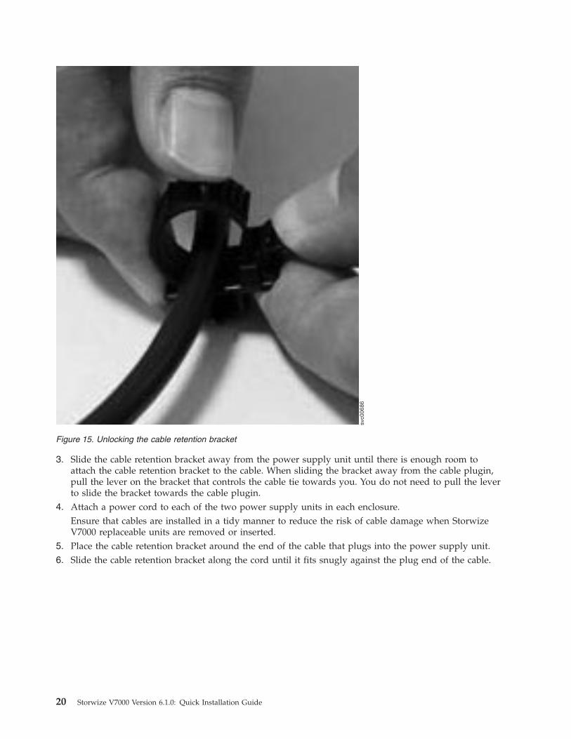
3. Slide the cable retention bracket away from the power supply unit until there is enough room toattach the cable retention bracket to the cable. When sliding the bracket away from the cable plugin,pull the lever on the bracket that controls the cable tie towards you. You do not need to pull the leverto slide the bracket towards the cable plugin.
4. Attach a power cord to each of the two power supply units in each enclosure.Ensure that cables are installed in a tidy manner to reduce the risk of cable damage when StorwizeV7000 replaceable units are removed or inserted.
5. Place the cable retention bracket around the end of the cable that plugs into the power supply unit.6. Slide the cable retention bracket along the cord until it fits snugly against the plug end of the cable.
svc00686
Figure 15. Unlocking the cable retention bracket
20 Storwize V7000 Version 6.1.0: Quick Installation Guide

7. Tighten the fastener around the plug.8. Repeat the steps for each additional power cord.9. Plug the power cords into a properly grounded electrical outlet. To provide power failure redundancy,
plug the power cords for the individual power supply units for each enclosure into separate powerdistribution circuits, if possible.
Step 12. Powering on the system
Attention: Do not operate the system when the drive assemblies are missing. Drive assemblies that aremissing disrupt the airflow; the drives do not receive sufficient cooling. You must insert blank carriersinto unused drive bays.1. Power on all expansion enclosures. Use the power switch on each of the two power supply units in
the back of the expansion enclosure.2. Use the information in Table 2 on page 22 to verify the state of the LEDs on the system. Verify that no
faults are detected. See the IBM Storwize V7000 Troubleshooting, Recovery, and Maintenance Guide PDFon the DVD if problems are encountered.Figure 17 on page 22 shows the location of the LEDs on the power supply units in the rear of theexpansion enclosure.
svc00644
Figure 16. Sliding the cable retention bracket directly behind the power cord
Chapter 2. Performing the hardware installation 21

Table 2. LED status when expansion enclosures are powered on
Hardware component LED name and symbol If power on and no fault is detected
Left enclosure end cap, front ofenclosure Power, top
LED is on.
Fault, middleLED is off.
Identify, bottomLED is off.
Expansion canister, rear. Thereference to the top and bottomlocations applies to canister 1, whichis the upper canister. The LEDlocations are inverted for canister 2,which is the lower canister.
Canister status, topLED is on.
Fault status, bottomLED is off.
Power supply unit, expansionenclosure. The reference to the leftand right locations applies to powersupply unit 1, which is the left powersupply. The LED locations areinverted for power supply unit 2,which is the right power supply.
Power supply, upper rightLED is on.
Fan failureLED is off.
dc power failure LED is off.
ac power failure, upper left LED is off.
3. Power on the control enclosure by using the power switch on each of the two power supply units inthe back of the enclosure.
4. Use the Table 3 on page 23 to verify the state of the LEDs on the system. Verify that no faults aredetected.Figure 18 on page 23 shows the location of the LEDs on the power supply units in the rear of thecontrol enclosure.
1
svc00671
1
Figure 17. LEDs on the power supply units of the expansion enclosure
22 Storwize V7000 Version 6.1.0: Quick Installation Guide
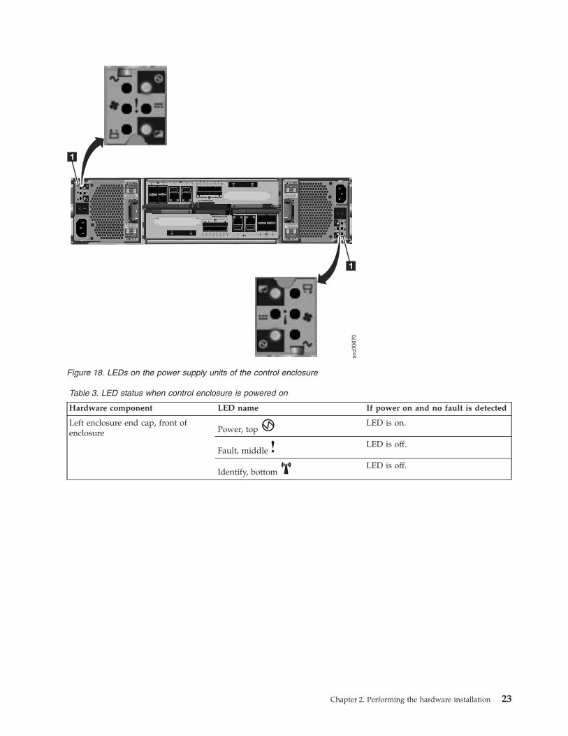
Table 3. LED status when control enclosure is powered on
Hardware component LED name If power on and no fault is detected
Left enclosure end cap, front ofenclosure Power, top
LED is on.
Fault, middleLED is off.
Identify, bottomLED is off.
svc00670
1
1
Figure 18. LEDs on the power supply units of the control enclosure
Chapter 2. Performing the hardware installation 23
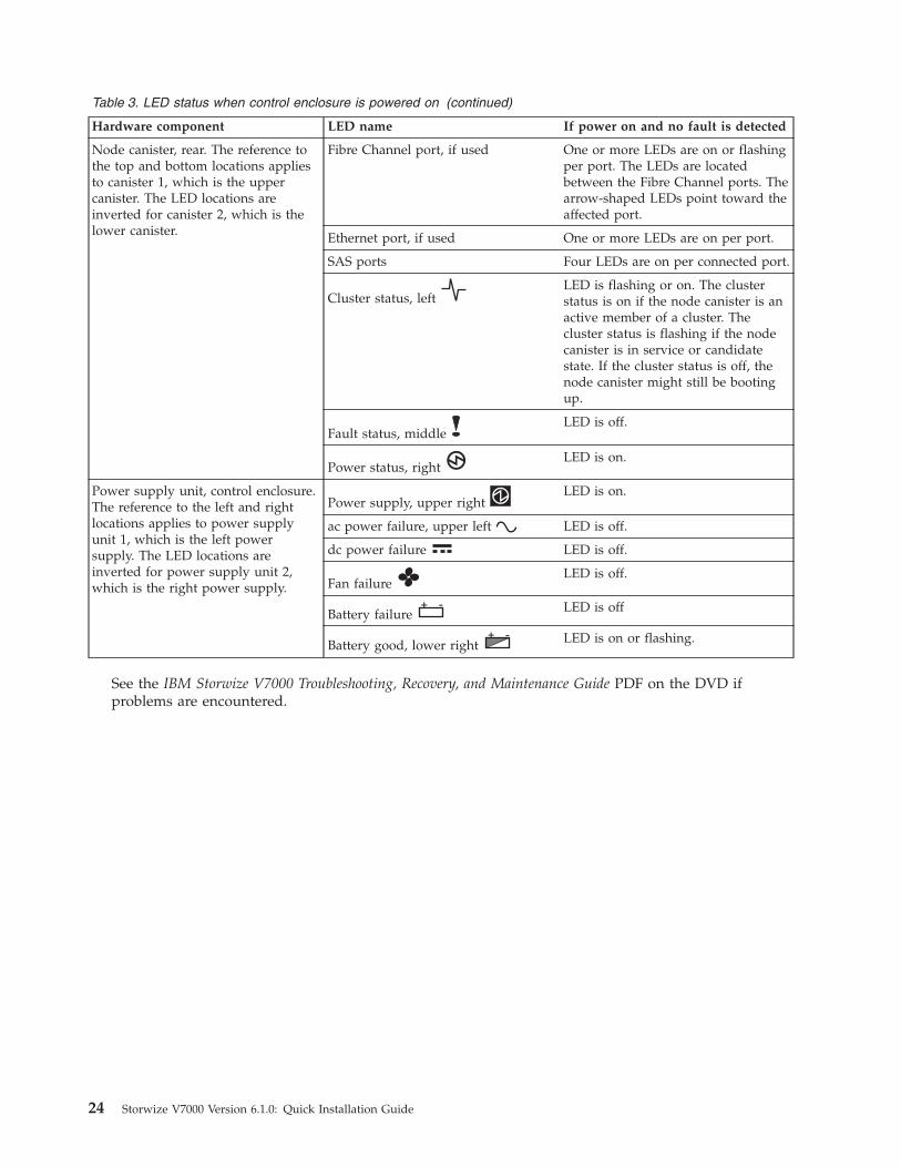
Table 3. LED status when control enclosure is powered on (continued)
Hardware component LED name If power on and no fault is detected
Node canister, rear. The reference tothe top and bottom locations appliesto canister 1, which is the uppercanister. The LED locations areinverted for canister 2, which is thelower canister.
Fibre Channel port, if used One or more LEDs are on or flashingper port. The LEDs are locatedbetween the Fibre Channel ports. Thearrow-shaped LEDs point toward theaffected port.
Ethernet port, if used One or more LEDs are on per port.
SAS ports Four LEDs are on per connected port.
Cluster status, leftLED is flashing or on. The clusterstatus is on if the node canister is anactive member of a cluster. Thecluster status is flashing if the nodecanister is in service or candidatestate. If the cluster status is off, thenode canister might still be bootingup.
Fault status, middleLED is off.
Power status, rightLED is on.
Power supply unit, control enclosure.The reference to the left and rightlocations applies to power supplyunit 1, which is the left powersupply. The LED locations areinverted for power supply unit 2,which is the right power supply.
Power supply, upper rightLED is on.
ac power failure, upper left LED is off.
dc power failure LED is off.
Fan failureLED is off.
Battery failure+ - LED is off
Battery good, lower right+ - LED is on or flashing.
See the IBM Storwize V7000 Troubleshooting, Recovery, and Maintenance Guide PDF on the DVD ifproblems are encountered.
24 Storwize V7000 Version 6.1.0: Quick Installation Guide
Chapter 3. Configuring the system
In the previous steps, you installed the enclosures in the rack, connected all cables, powered the systemon, and checked the LED status for the system. When you have completed all these steps, continue withthe last step to configure the system.
The last step for configuring your system provides instructions for two scenarios. Follow the first set ofinstructions when you are setting up your system for the first time. Follow the second set of instructionswhen you have an existing system and are now adding one or more expansion enclosures to the existingsystem.
Step 13. Configuring the system
To complete this step, you must use a supported browser. Verify that you are using a supported browserfrom the following website:
Support for Storwize V7000 website at www.ibm.com/storage/support/storwize/v7000v Scenario 1: Setting up your system for the first time with a control enclosure or a control enclosure
and one or more expansion enclosures.
You must initialize the system by creating a cluster and configuring it. The first stage is to create thecluster using the initialization tool and the USB key. You must know the required cluster managementIP address before continuing.1. Locate the USB key that was shipped with your order in the documentation package.2. Insert the USB key into a USB port in a personal computer that is running Microsoft Windows XP
Professional or higher.Start the initialization tool.If the system is configured to autorun for USB keys, the initialization tool starts automatically.Otherwise, open the USB key from My Computer and double-click the InitTool.exe.
© Copyright IBM Corp. 2010 25
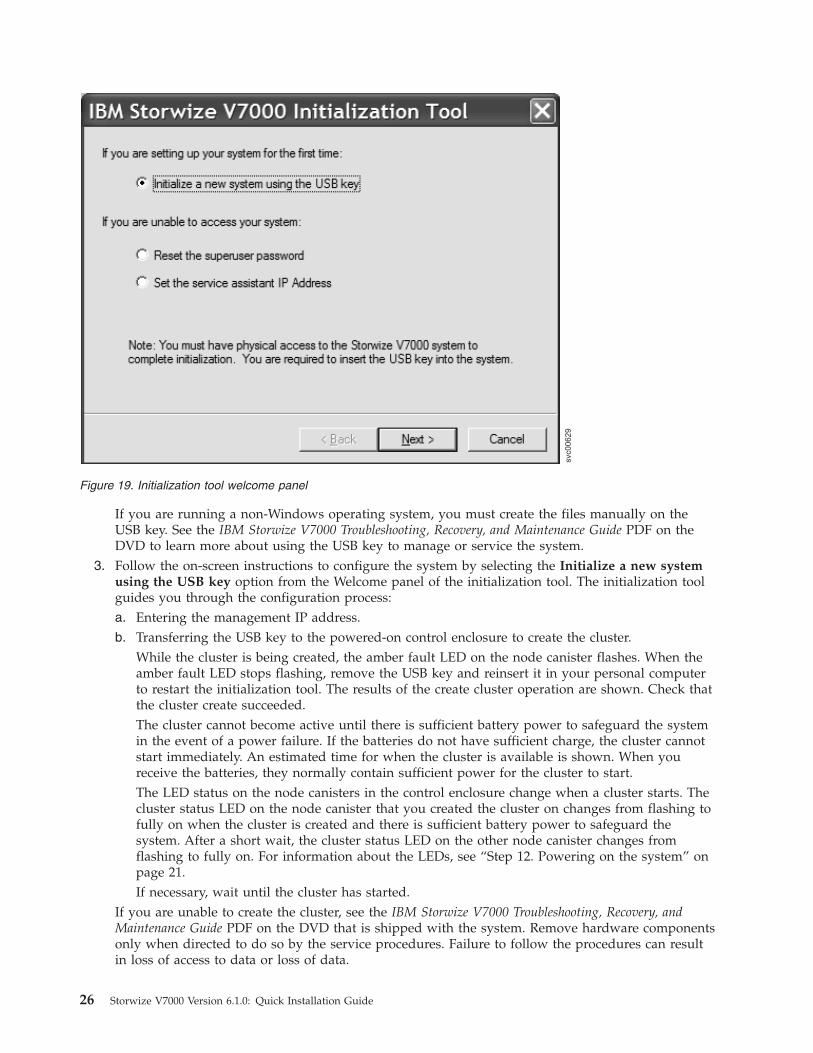
If you are running a non-Windows operating system, you must create the files manually on theUSB key. See the IBM Storwize V7000 Troubleshooting, Recovery, and Maintenance Guide PDF on theDVD to learn more about using the USB key to manage or service the system.
3. Follow the on-screen instructions to configure the system by selecting the Initialize a new systemusing the USB key option from the Welcome panel of the initialization tool. The initialization toolguides you through the configuration process:a. Entering the management IP address.b. Transferring the USB key to the powered-on control enclosure to create the cluster.
While the cluster is being created, the amber fault LED on the node canister flashes. When theamber fault LED stops flashing, remove the USB key and reinsert it in your personal computerto restart the initialization tool. The results of the create cluster operation are shown. Check thatthe cluster create succeeded.The cluster cannot become active until there is sufficient battery power to safeguard the systemin the event of a power failure. If the batteries do not have sufficient charge, the cluster cannotstart immediately. An estimated time for when the cluster is available is shown. When youreceive the batteries, they normally contain sufficient power for the cluster to start.The LED status on the node canisters in the control enclosure change when a cluster starts. Thecluster status LED on the node canister that you created the cluster on changes from flashing tofully on when the cluster is created and there is sufficient battery power to safeguard thesystem. After a short wait, the cluster status LED on the other node canister changes fromflashing to fully on. For information about the LEDs, see “Step 12. Powering on the system” onpage 21.If necessary, wait until the cluster has started.
If you are unable to create the cluster, see the IBM Storwize V7000 Troubleshooting, Recovery, andMaintenance Guide PDF on the DVD that is shipped with the system. Remove hardware componentsonly when directed to do so by the service procedures. Failure to follow the procedures can resultin loss of access to data or loss of data.
svc00629
Figure 19. Initialization tool welcome panel
26 Storwize V7000 Version 6.1.0: Quick Installation Guide

If you are unable to start the management GUI, see the IBM Storwize V7000 Troubleshooting,Recovery, and Maintenance Guide PDF on the DVD that is shipped with the system.
4. If the personal computer from which you are using the initialization tool has a supported browserand an Ethernet connection to the cluster IP address, click Launch the management GUI on theresults window. Otherwise, go to a personal computer that has an Ethernet connection to the clusterIP address and point a supported browser to the management IP address to start the managementGUI. You see the management GUI logon panel.For assistance in troubleshooting a problem, see the IBM Storwize V7000 Troubleshooting, Recovery,and Maintenance Guide PDF on the DVD that is shipped with the system.
5. Log in as superuser. Use passw0rd for the password.
Note: Change the password to a secure value as soon as possible.6. Review the International Program License Agreement (IPLA).
You must accept the agreement before you can continue to use the product.7. The Setup wizard starts and guides you through the initial configuration and verification of the
system.If you are not ready to complete any of the configuration steps now, use the configuration tasks inthe management GUI to complete the configuration at a later time.
8. When you are finished using the USB key, store it in a safe location. You can use it to do othertasks.
v Scenario 2: Adding an expansion enclosure into an existing system.
1. Start the management GUI.2. Go to Home → Manage Device.3. Select the system name in the tree.4. Go to Actions → Add Enclosure.5. Continue to follow the on-screen instructions.
This step completes the quick installation procedures. If you are setting up for the first time, see theconfiguring topics in the Storwize V7000 Information Center and continue to follow the tasks available inGetting Started from the management GUI. If you added an expansion enclosure into an existing system,continue to perform your standard tasks.
Chapter 3. Configuring the system 27

28 Storwize V7000 Version 6.1.0: Quick Installation Guide

Notices
This information was developed for products and services offered in the U.S.A.
IBM may not offer the products, services, or features discussed in this document in other countries.Consult your local IBM representative for information on the products and services currently available inyour area. Any reference to an IBM product, program, or service is not intended to state or imply thatonly that IBM product, program, or service may be used. Any functionally equivalent product, program,or service that does not infringe any IBM intellectual property right may be used instead. However, it isthe user's responsibility to evaluate and verify the operation of any non-IBM product, program, orservice.
IBM may have patents or pending patent applications covering subject matter described in thisdocument. The furnishing of this document does not give you any license to these patents. You can sendlicense inquiries, in writing, to:
IBM Director of LicensingIBM CorporationNorth Castle DriveArmonk, NY 10504-1785U.S.A.
For license inquiries regarding double-byte (DBCS) information, contact the IBM Intellectual PropertyDepartment in your country or send inquiries, in writing, to:
Intellectual Property LicensingLegal and Intellectual Property LawIBM Japan, Ltd.1623-14, Shimotsuruma, Yamato-shiKanagawa 242-8502 Japan
The following paragraph does not apply to the United Kingdom or any other country where suchprovisions are inconsistent with local law: INTERNATIONAL BUSINESS MACHINES CORPORATIONPROVIDES THIS PUBLICATION "AS IS" WITHOUT WARRANTY OF ANY KIND, EITHER EXPRESS ORIMPLIED, INCLUDING, BUT NOT LIMITED TO, THE IMPLIED WARRANTIES OFNON-INFRINGEMENT, MERCHANTABILITY OR FITNESS FOR A PARTICULAR PURPOSE. Somestates do not allow disclaimer of express or implied warranties in certain transactions, therefore, thisstatement may not apply to you.
This information could include technical inaccuracies or typographical errors. Changes are periodicallymade to the information herein; these changes will be incorporated in new editions of the publication.IBM may make improvements and/or changes in the product(s) and/or the program(s) described in thispublication at any time without notice.
Any references in this information to non-IBM websites are provided for convenience only and do not inany manner serve as an endorsement of those websites. The materials at those websites are not part ofthe materials for this IBM product and use of those websites is at your own risk.
IBM may use or distribute any of the information you supply in any way it believes appropriate withoutincurring any obligation to you.
© Copyright IBM Corp. 2010 29

Licensees of this program who wish to have information about it for the purpose of enabling: (i) theexchange of information between independently created programs and other programs (including thisone) and (ii) the mutual use of the information which has been exchanged, should contact:
IBM CorporationAlmaden Research650 Harry RoadBldg 80, D3-304, Department 277San Jose, CA 95120-6099U.S.A.
Such information may be available, subject to appropriate terms and conditions, including in some cases,payment of a fee.
The licensed program described in this document and all licensed material available for it are providedby IBM under terms of the IBM Customer Agreement, IBM International Program License Agreement orany equivalent agreement between us.
Any performance data contained herein was determined in a controlled environment. Therefore, theresults obtained in other operating environments may vary significantly. Some measurements may havebeen made on development-level systems and there is no guarantee that these measurements will be thesame on generally available systems. Furthermore, some measurement may have been estimated throughextrapolation. Actual results may vary. Users of this document should verify the applicable data for theirspecific environment.
Information concerning non-IBM products was obtained from the suppliers of those products, theirpublished announcements or other publicly available sources. IBM has not tested those products andcannot confirm the accuracy of performance, compatibility or any other claims related to non-IBMproducts. Questions on the capabilities of non-IBM products may be addressed to the suppliers of thoseproducts.
All statements regarding IBM's future direction or intent are subject to change or withdrawal withoutnotice, and represent goals and objectives only.
This information is for planning purposes only. The information herein is subject to change before theproducts described become available.
This information contains examples of data and reports used in daily business operations. To illustratethem as completely as possible, the examples include the names of individuals, companies, brands, andproducts. All of these names are fictitious and any similarity to the names and addresses used by anactual business enterprise is entirely coincidental.
COPYRIGHT LICENSE:
This information contains sample application programs in source language, which illustrate programmingtechniques on various operating platforms. You may copy, modify, and distribute these sample programsin any form without payment to IBM, for the purposes of developing, using, marketing or distributingapplication programs conforming to the application programming interface for the operating platform forwhich the sample programs are written. These examples have not been thoroughly tested under allconditions. IBM, therefore, cannot guarantee or imply reliability, serviceability, or function of theseprograms. The sample programs are provided "AS IS", without warranty of any kind. IBM shall not beliable for any damages arising out of your use of the sample programs.
If you are viewing this information softcopy, the photographs and color illustrations may not appear.
30 Storwize V7000 Version 6.1.0: Quick Installation Guide

Trademarks
IBM, the IBM logo, and ibm.com are trademarks or registered trademarks of International BusinessMachines Corp., registered in many jurisdictions worldwide. Other product and service names might betrademarks of IBM or other companies. A current list of IBM trademarks is available on the web atCopyright and trademark information at www.ibm.com/legal/copytrade.shtml.
Adobe and the Adobe logo are either registered trademarks or trademarks of Adobe SystemsIncorporated in the United States, and/or other countries.
Intel, Intel logo, Intel Xeon, and Pentium are trademarks or registered trademarks of Intel Corporation orits subsidiaries in the United States and other countries.
Java and all Java-based trademarks and logos are trademarks of Sun Microsystems, Inc. in the UnitedStates, other countries, or both.
Linux is a registered trademark of Linus Torvalds in the United States, other countries, or both.
Microsoft, Windows, Windows NT, and the Windows logo are trademarks of Microsoft Corporation in theUnited States, other countries, or both.
UNIX is a registered trademark of The Open Group in the United States and other countries.
Other company, product, or service names may be trademarks or service marks of others.
Electronic emission noticesThe following electronic emission statements apply to this product. The statements for other productsthat are intended for use with this product are included in their accompanying documentation.
Federal Communications Commission (FCC) statementThis explains the Federal Communications Commission's (FCC) statement.
This equipment has been tested and found to comply with the limits for a Class A digital device,pursuant to Part 15 of the FCC Rules. These limits are designed to provide reasonable protection againstharmful interference when the equipment is operated in a commercial environment. This equipmentgenerates, uses, and can radiate radio frequency energy and, if not installed and used in accordance withthe instruction manual, might cause harmful interference to radio communications. Operation of thisequipment in a residential area is likely to cause harmful interference, in which case the user will berequired to correct the interference at his own expense.
Properly shielded and grounded cables and connectors must be used in order to meet FCC emissionlimits. IBM is not responsible for any radio or television interference caused by using other thanrecommended cables and connectors, or by unauthorized changes or modifications to this equipment.Unauthorized changes or modifications could void the user's authority to operate the equipment.
This device complies with Part 15 of the FCC Rules. Operation is subject to the following two conditions:(1) this device might not cause harmful interference, and (2) this device must accept any interferencereceived, including interference that might cause undesired operation.
Notices 31

Industry Canada compliance statement
This Class A digital apparatus complies with ICES-003.
Cet appareil numérique de la classe A est conform à la norme NMB-003 du Canada.
Avis de conformité à la réglementation d'Industrie CanadaCet appareil numérique de la classe A est conforme à la norme NMB-003 du Canada.
Australia and New Zealand Class A Statement
Attention: This is a Class A product. In a domestic environment this product might cause radiointerference in which case the user might be required to take adequate measures.
European Union Electromagnetic Compatibility Directive
This product is in conformity with the protection requirements of European Union (EU) Council Directive2004/108/EC on the approximation of the laws of the Member States relating to electromagneticcompatibility. IBM cannot accept responsibility for any failure to satisfy the protection requirementsresulting from a non-recommended modification of the product, including the fitting of non-IBM optioncards.
Attention: This is an EN 55022 Class A product. In a domestic environment this product might causeradio interference in which case the user might be required to take adequate measures.
Responsible Manufacturer:
International Business Machines Corp.New Orchard RoadArmonk, New York 10504914-499-1900
European community contact:
IBM Technical Regulations, Department M456IBM-Allee 1, 71137 Ehningen, GermanyTel: +49 7032 15-2937E-mail: [email protected]
Germany Electromagnetic compatibility directive
Deutschsprachiger EU Hinweis: Hinweis für Geräte der Klasse A EU-Richtlinie zurElektromagnetischen Verträglichkeit
Dieses Produkt entspricht den Schutzanforderungen der EU-Richtlinie 2004/108/EG zur Angleichung derRechtsvorschriften über die elektromagnetische Verträglichkeit in den EU-Mitgliedsstaaten und hält dieGrenzwerte der EN 55022 Klasse A ein.
Um dieses sicherzustellen, sind die Geräte wie in den Handbüchern beschrieben zu installieren und zubetreiben. Des Weiteren dürfen auch nur von der IBM empfohlene Kabel angeschlossen werden. IBMübernimmt keine Verantwortung für die Einhaltung der Schutzanforderungen, wenn das Produkt ohneZustimmung der IBM verändert bzw. wenn Erweiterungskomponenten von Fremdherstellern ohneEmpfehlung der IBM gesteckt/eingebaut werden.
32 Storwize V7000 Version 6.1.0: Quick Installation Guide

EN 55022 Klasse A Geräte müssen mit folgendem Warnhinweis versehen werden:
"Warnung: Dieses ist eine Einrichtung der Klasse A. Diese Einrichtung kann im WohnbereichFunk-Störungen verursachen; in diesem Fall kann vom Betreiber verlangt werden, angemesseneMabnahmen zu ergreifen und dafür aufzukommen."
Deutschland: Einhaltung des Gesetzes über die elektromagnetische Verträglichkeitvon Geräten
Dieses Produkt entspricht dem "Gesetz über die elektromagnetische Verträglichkeit von Geräten (EMVG)."Dies ist die Umsetzung der EU-Richtlinie 2004/108/EG in der Bundesrepublik Deutschland.
Zulassungsbescheinigung laut dem Deutschen Gesetz über dieelektromagnetische Verträglichkeit von Geräten (EMVG) (bzw. der EMC EGRichtlinie 2004/108/EG) für Geräte der Klasse A
Dieses Gerät ist berechtigt, in übereinstimmung mit dem Deutschen EMVG das EG-Konformitätszeichen -CE - zu führen.
Verantwortlich für die Einhaltung der EMV Vorschriften ist der Hersteller:International Business Machines Corp.New Orchard RoadArmonk,New York 10504Tel: 914-499-1900
Der verantwortliche Ansprechpartner des Herstellers in der EU ist:
IBM DeutschlandTechnical Regulations, Department M456IBM-Allee 1, 71137 Ehningen, GermanyTel: +49 7032 15-2937e-mail: [email protected]
Generelle Informationen: Das Gerät erfüllt die Schutzanforderungen nach EN55024 und EN 55022 Klasse A.
Japan VCCI Council Class A statement
People's Republic of China Class A Electronic Emission Statement
Notices 33

International Electrotechnical Commission (IEC) statementThis product has been designed and built to comply with (IEC) Standard 950.
United Kingdom telecommunications requirements
This apparatus is manufactured to the International Safety Standard EN60950 and as such is approved inthe U.K. under approval number NS/G/1234/J/100003 for indirect connection to publictelecommunications systems in the United Kingdom.
Korean Communications Commission (KCC) Class A Statement
Russia Electromagnetic Interference (EMI) Class A Statement
Taiwan Class A compliance statement
European Contact InformationThis topic contains the product service contact information for Europe.European Community contact:IBM Technical RegulationsPascalstr. 100, Stuttgart, Germany 70569Tele: 0049 (0)711 785 1176Fax: 0049 (0)711 785 1283Email: mailto:[email protected]
rusem
i
34 Storwize V7000 Version 6.1.0: Quick Installation Guide

Taiwan Contact InformationThis topic contains the product service contact information for Taiwan.IBM Taiwan Product Service Contact Information:IBM Taiwan Corporation3F, No 7, Song Ren Rd., Taipei TaiwanTel: 0800-016-888
f2c0
07
90
Notices 35

36 Storwize V7000 Version 6.1.0: Quick Installation Guide


����
Part Number: 85Y5979
Printed in USA
GC27-2290-00
(1P)
P/N:
85Y5
979


![IBM Storwize V3500img.zhilankeji.com/ibm/storwize_v3500_01.pdf · 2013-12-18 · IBM Storwize V7000 2010 年 10 ... V7000 Storwize V7000 [ Unified ] DS4000, DS5000, Storwize V7000](https://img.pdfslide.net/doc/110x75/5f8da2e2ad21c4137b6552e2/ibm-storwize-2013-12-18-ibm-storwize-v7000-2010-10-v7000-storwize-v7000.jpg)