Embed Size (px)
Citation preview

ICT EU OneFIT 30.06.2012
OneFIT Deliverable D5.2
1/117
Validation platform implementation description – D5.2
Project Number: ICT-2009-257385
Project Title: Opportunistic networks and Cognitive Management Systems for Efficient Application Provision in the Future
Internet - OneFIT Document Type: Deliverable
Contractual Date of Delivery: 30.06.2012
Actual Date of Delivery: 20.07.2012
Editors: Milenko Tosic (LCI)
Participants: Please see contributors’ list
Workpackage: WP5
Estimated Person Months: 69 PMs
Nature: PU - Public
Version: 1.0
Total Number of Pages: 117
File: OneFIT_D5.2_20120630.doc
Abstract This deliverable describes different test-beds for the validation of the architecture, algorithms and protocols for the operator governed opportunistic networking as defined in the OneFIT Project. Further on, this deliverable provides a description of the implementation of the OneFIT cognitive management systems CSCI and CMON as well as the C4MS protocol. Also, implementation of the blocks supporting the OneFIT system (JRRM, CCM, DSONPM, and DSM) is described. This document also describes the implementation of the OneFIT scenarios for opportunistic coverage extension, opportunistic capacity extension, infrastructure supported ad-hoc networking and device-to-device communication as well as opportunistic resource aggregation in the backhaul network.
Keywords List OneFIT validation platform, implementation, OneFIT system building blocks, CMON, CSCI, C4MS, JRRM, CCM, DSM, DSONPM, Opportunistic Networks, management phases, OneFIT scenarios, test-bed

ICT EU OneFIT 30.06.2012
OneFIT Deliverable D5.2
2/117
Executive Summary
This document describes the implementation of the OneFIT [1] platform components for the management of operator governed opportunistic networks into the OneFIT validation platform which is introduced in D5.1 [2] and further described in this document.
First, test-beds which are brought by OneFIT consortium members are described and mapped onto the overall OneFIT validation platform. A description of every test-bed provides insights into the OneFIT algorithms for operator governed opportunistic networking and protocol variants for the control channels for the cooperation of cognitive management systems (C4MS) which are implemented into the test-bed.
The implementation of the “Cognitive Management system for the Opportunistic Network” (CMON) and the “Cognitive management System for the Coordination of the Infrastructure“ (CSCI) as well as the implementation of other building blocks, necessary for OneFIT system realization (including parts of the OneFIT functional architecture – Dynamic Spectrum Management (DSM), Joint Radio Resource Management (JRRM), Configuration Control Module (CCM) and Dynamic and Self-Organizing Network Planning and Management (DSONPM)), in these test-beds is described. Finally, possible and ongoing cooperation between different test-beds are mentioned. Fulfilment of the OneFIT system requirements by the current implementation of the OneFIT platform is presented. Framed in this context, essential requirements related to the establishment and management of the ON and general requirements (e.g. mobility, relaying, communication with infrastructure and between terminals etc.) are taken into account in the current implementation of the OneFIT system. Additionally, user (e.g. hide complexity from the user), algorithmic (e.g. context awareness, decision making mechanisms etc.), protocol (e.g. usage of standardized protocols, unicast communication etc.) and security requirements are sufficiently covered and will be further expanded.
Section 3 describes the implementation of the OneFIT cognitive management system and lists the WP4 algorithms which are implemented into the validation platform. A mapping of the implemented algorithms onto CMON and CSCI tasks as well as ON management phases is described in detail. The implemented versions of OneFIT algorithms provide all necessary functionalities for achieving cognitive management of opportunistic networks (e.g. context, policies, profiles acquisition and management, decision making, solution enforcement, ON creation/maintenance/termination). Different OneFIT algorithms cooperate in order to provide necessary functionalities of the OneFIT cognitive management system. Some of the algorithms address the same challenges, but in different context (RAT, type of the network, different triggers, different nodes involved etc.).
Section 4 of this deliverable presents implementation of supporting blocks, which are presented in functional architecture of the OneFIT system. These building blocks are JRRM, CCM, DSM and DSONPM. The aforementioned building blocks are built on legacy functionalities and expanded in the context of the OneFIT functional architecture in order to include essential features of the ONs.
Implemented variants of the C4MS protocol are described in section 5. First, the 802.21 MIH based C4MS implementation is presented. Next, the implementation of supporting C4MS signalling using IETF OLSR and SNMP is described. Implemented C4MS variants provide required functionalities for enabling context acquisition and signalling support throughout the ON lifecycle phases.
At the end of the deliverable, the realization of the OneFIT scenarios for opportunistic coverage extension, opportunistic capacity extension, infrastructure supported ad-hoc networking and device-to-device communication as well as opportunistic resource aggregation in the backhaul network within the OneFIT validation platform is presented. Each scenario implementation description specifies which test-beds and OneFIT building blocks (ON enabling algorithms, C4MS variants and OneFIT supporting blocks) are utilized.

ICT EU OneFIT 30.06.2012
OneFIT Deliverable D5.2
3/117
Contributors
First Name Last Name Affiliation Email
Milenko Tosic LCI [email protected]
Ognjen Ikovic LCI [email protected]
Dragan Boskovic LCI [email protected]
Mirko Cirilovic LCI [email protected]
Jens Gebert ALUD [email protected]
Rolf Fuchs ALUD [email protected]
Andreas Wich ALUD [email protected]
Jordi Pérez-Romero UPC [email protected]
Oriol Sallent UPC [email protected]
Ramon Ferrús UPC [email protected]
Alessandro Raschellà UPC [email protected]
Dimitrios Karvounas UPRC [email protected]
Andreas Georgakopoulos UPRC [email protected]
Vera Stavroulaki UPRC [email protected]
Nikos Koutsouris UPRC [email protected]
Kostas Tsagkaris UPRC [email protected]
Panagiotis Demestichas UPRC [email protected]
Markus Mueck IMC [email protected]
Christian Drewes IMC [email protected]
Florian Nehring IMC [email protected]
Guenter Moser IMC [email protected]
Óscar Moreno TID [email protected]
José Luis González TID [email protected]
Thomas Delsol NTUK [email protected]
Christian Mouton NTUK [email protected]
Seiamak Vahid UNIS [email protected]

ICT EU OneFIT 30.06.2012
OneFIT Deliverable D5.2
4/117
Table of Acronyms
Term Meaning
3G 3rd Generation
3GPP 3rd Generation Partnership Project
ACK Acknowledgement
ACL Agent Communication Language
AID Action Identifier
AP Access Point
BS Base Station
BSSID Basic Service Set Identifier
C4MS Control Channels for the Cooperation of the Cognitive Management System
CA Context Awareness
CCM Configuration Control Module
CMON Cognitive Management system for the Opportunistic Network
CO Carbon Oxide
CPU Central Processing Unit
CR Cognitive Radio
CRSM Cognitive Radio System Management
CS Circuit Switched
CSCI Cognitive management System for the Coordination of the Infrastructure
D2D Device to Device
DBMS Data Base Management System
DHCP Dynamic Host Configuration Protocol
DM Decision Making
DRA Dynamic Resource Allocation
DSM Dynamic Spectrum Management
DSONPM Dynamic and Self-Organizing Network Planning and Management
EDGE Enhanced Data for Global Evolution
ETX Expected Transmission Count
FA Functional Architecture
FIPA Foundation for Intelligent Physical Agents
FTP File Transfer Protocol
GPRS General packet radio service

ICT EU OneFIT 30.06.2012
OneFIT Deliverable D5.2
5/117
GSM Global System for Mobile Communications
GUI Graphical User Interface
GW Gateway
HNA Host and Network Association
HSDPA High-Speed Downlink Packet Access
HTTP Hyper-Text Transfer Protocol
IETF Internet Engineering Task Force
INA Information Answer
INI Information Indication
INR Information Request
IP Internet Protocol
ISM Industrial Scientific and Medical
JADE Java Agent DEvelopment Platform
JMF Java Media Framework
JRRM Joint Radio Resource Management
KPI Key Performance Indicator
LAN Local Area Network
LTE Long Term Evolution
MAC Medium Access Control
MAS Multi Agent System
MID Multiple Interface Declaration
MIH Media Independent Handover
MIHF Media Independent Handover Function
MNO Mobile Network Operator
MPR Multi-Point Relay
MRRM Multi standard Radio Resource Management
MSC Message Sequence Chart
NAT Network Address Translator
NIC Network Interface Controller
OBD On-Board Diagnostics
OF Objective Function
ON Opportunistic Network
ONC Opportunistic Network Creation
ONE Opportunistic Network Environment

ICT EU OneFIT 30.06.2012
OneFIT Deliverable D5.2
6/117
OneFIT Opportunistic networks and Cognitive Management Systems for Efficient Application Provision in the Future InterneT
ONM Opportunistic Network Modification
ONN Opportunistic Network Negotiation
ONNA ON-Negotiation-Answer
ONNR ON-Negotiation-Request
ONRA ON-Release-Answer
ONRR ON-Release-Request
ONSN Opportunistic Network Status Notification
OLSR Optimised Link State Routing
OPA Operator Policy Acquisition
PC Personal Computer
PDU Protocol Data Unit/ Packet Data Unit
PLMN Public Land Mobile Network
PM Profile Management
QoE Quality of Experience
QoS Quality of Service
RAT Radio Access Technology
RB Router Board
RDQ-A RAT-Demand-QoS Assignment
RRC Radio Resource Control
RRM Radio Resource Management
SA System Architecture
SAP Service Access Point
SID Service Identifier
SIM Subscriber Identity Module
SINR Signal to Interference plus Noise Ratio
SIP Session Initiation Protocol
SNMP Simple Network Management Protocol
SQL Structured Query Language
SSID Service Set IDentifier
STUN Session Traversal Utilities for NAT
SUMO Simulation of Urban MObility
TC Topology Control
TCP Transmission Control Protocol

ICT EU OneFIT 30.06.2012
OneFIT Deliverable D5.2
7/117
TLV Type Length Value
Tx Transmission
UDP User Datagram Protocol
UE User Equipment
UMTS Universal Mobile Telecommunications System
USRP Universal Software Radio Peripheral
UTRAN Universal Terrestrial Radio Access Network
VoIP Voice over IP
WARP Wireless open-Access Research Platform
WLAN Wireless Local Area Network
WMN Wireless Mesh Network

ICT EU OneFIT 30.06.2012
OneFIT Deliverable D5.2
8/117
Table of Contents
1 Introduction ........................................................................................................................................... 15
2 OneFIT validation platform.............................................................................................................. 17
2.1 Prototyping platform for the management of opportunistic networks .................................................. 20
2.1.1 Addressed system requirements .................................................................................................... 23
2.2 Opportunistic networking demonstrator ................................................................................................ 25
2.2.1 Addressed system requirements .................................................................................................... 27
2.3 Opportunistic service provision demonstrator ....................................................................................... 27
2.3.1 Addressed system requirements .................................................................................................... 31
2.4 Opportunistic ad-hoc network routing demonstration ........................................................................... 32
2.4.1 Addressed system requirements .................................................................................................... 33
2.5 Prototyping platform for opportunistic coverage extension and related support functions .................. 33
2.5.1 Addressed system requirements .................................................................................................... 37
2.6 Direct D2D communication test-bed ....................................................................................................... 38
2.6.1 Addressed system requirements .................................................................................................... 41
2.7 Cognitive radio test-bed .......................................................................................................................... 42
2.7.1 Addressed system requirements .................................................................................................... 44
2.8 Spectrum opportunity identification and spectrum selection test-bed .................................................. 45
2.8.1 Addressed system requirements .................................................................................................... 48
2.9 Open platform wireless mesh network test-bed ..................................................................................... 49
2.9.1 Addressed system requirements .................................................................................................... 50
3 Implementation of the OneFIT cognitive management system .......................................... 53
3.1 Implementation of the CSCI .................................................................................................................... 56
3.2 Implementation of the CMON ................................................................................................................. 59
3.3 Implementation of ON management phases .......................................................................................... 60
3.3.1 ON suitability determination .......................................................................................................... 60
3.3.2 ON creation ..................................................................................................................................... 67
3.3.3 ON maintenance and termination .................................................................................................. 79
4 Implementation of supporting OneFIT building blocks ........................................................ 82
4.1 Implementation of the JRRM .................................................................................................................. 82
4.2 Implementation of the DSM .................................................................................................................... 83
4.3 Implementation of the CCM .................................................................................................................... 84
4.4 Implementation of the DSONPM ............................................................................................................. 85
5 Implementation of the C4MS protocol ......................................................................................... 87
5.1 IEEE 802.21 for device-to-device and terminal-network communication ............................................... 87
5.1.1 IEEE 802.21 based C4MS protocol overview .................................................................................. 89

ICT EU OneFIT 30.06.2012
OneFIT Deliverable D5.2
9/117
5.1.2 IEEE 802.21 protocol header format............................................................................................... 89
5.1.3 IEEE 802.21 parameter format ....................................................................................................... 90
5.1.4 Procedures and messages .............................................................................................................. 90
5.2 IETF OLSR for route discovery and management .................................................................................... 93
5.3 IETF SNMP for network management of infrastructure elements .......................................................... 97
6 Implementation of the OneFIT scenarios ................................................................................... 99
6.1 Implementation of the OneFIT scenario 1 “Opportunistic coverage extension” .................................. 100
6.1.1 Sub-scenario: Device going out of coverage ................................................................................. 100
6.1.2 Sub-scenario: Device cannot connect to infrastructure ............................................................... 100
6.2 Implementation of the OneFIT scenario 2 “Opportunistic capacity extension” ................................... 104
6.3 Implementation of the OneFIT scenario 3 “Infrastructure supported opportunistic ad-hoc networking” 106
6.3.1 Local video sharing implementation ............................................................................................. 107
6.3.2 Opportunistic Service Provision Demonstrator ............................................................................ 107
6.4 Implementation of the OneFIT scenario 5 “Opportunistic resource aggregation in the backhaul network” ............................................................................................................................................................. 109
7 Conclusion ........................................................................................................................................... 115
8 References ........................................................................................................................................... 116

ICT EU OneFIT 30.06.2012
OneFIT Deliverable D5.2
10/117
List of Figures
Figure 1: OneFIT functional architecture .............................................................................................. 15
Figure 2: OneFIT validation platform .................................................................................................... 17
Figure 3: Mapping of the test-beds responsible for spectrum selection/identification challenge onto the OneFIT scenarios and ON management phases ..................................................................... 18
Figure 4: Mapping of the test-beds responsible for nodes and routes selection/identification challenge onto the OneFIT scenarios and ON management phases ............................................ 19
Figure 5 : Mapping of the capacity extension through neighbouring terminals concept to the OneFIT functional architecture ................................................................................................................. 22
Figure 6 : Mapping of the selection of nodes through a fitness value evaluation concept to the OneFIT functional architecture ..................................................................................................... 22
Figure 7 : Mapping of the DRA concept functional entities to the OneFIT functional architecture ..... 23
Figure 8: Opportunistic Networking Demonstrator Overview ............................................................. 25
Figure 9: Mapping of the Opportunistic Networking Demonstrator to the OneFIT Architecture [4] .. 26
Figure 10: Simulated scenario ............................................................................................................... 28
Figure 11: Relationship between simulator entities ............................................................................. 29
Figure 12: System control structure and data-flow .............................................................................. 29
Figure 13: GUI screenshot (1) ............................................................................................................... 30
Figure 14: GUI screenshot (2) ............................................................................................................... 30
Figure 15: Opportunistic ad-hoc network routing platform ................................................................. 32
Figure 16: Test-bed software architecture ........................................................................................... 33
Figure 17: Overall architecture of Prototyping Platform for Opportunistic Coverage Extension and related Support Functions ............................................................................................................ 34
Figure 18: Instantiation of overall architecture of Prototyping Platform for Opportunistic Coverage Extension and related Support Functions ..................................................................................... 34
Figure 19: GUI indicating active wireless links and related key parameters ........................................ 35
Figure 20: GUI indicating test-bed configuration to be operated ........................................................ 36
Figure 21: GUI indicating operator policies to be met by mobile device decision making entities ..... 36
Figure 22: GUI showing live video streaming ....................................................................................... 37
Figure 23: Overall architecture of Prototyping Platform for Direct D2D communication .................... 39
Figure 24: Infrastructure use in the demonstrator ............................................................................... 40
Figure 25: ON “coverage extension” Scenario 1a – “Relaying” within infrastructure coverage .......... 42
Figure 26: ON “coverage extension” Scenario 1b – “Relaying” within ON coverage ........................... 43
Figure 27: Scenario considered in the demonstration ......................................................................... 45
Figure 28: Implementation of the demonstration scenario by means of USRP ................................... 46

ICT EU OneFIT 30.06.2012
OneFIT Deliverable D5.2
11/117
Figure 29: Mapping of the algorithm in the OneFIT architecture ......................................................... 46
Figure 30: Mapping of the functional entities of the fittingness factor-based spectrum selection onto the CMON ..................................................................................................................................... 47
Figure 31: Open platform WMN test-bed ............................................................................................. 50
Figure 32: Mapping of the implemented algorithms onto the ON related challenges, the ON management phases, CMON and CSCI entities and the OneFIT scenarios .................................. 54
Figure 33: Mapping of the algorithmic solutions onto the triggering events and states ..................... 55
Figure 34: Detailed functional view of the CSCI and CMON in the terminal ........................................ 56
Figure 35: Detailed functional view of the CSCI and CMON in the operator’s infrastructure .............. 56
Figure 36: Suitability Determination for the coverage extension scenario .......................................... 61
Figure 37: Algorithm on capacity extension of the infrastructure through neighbouring terminals ... 62
Figure 38: Algorithm on selection of nodes through a fitness value evaluation .................................. 63
Figure 39: Implementation of the selection of nodes through a fitness value evaluation concept in the OneFIT platform ...................................................................................................................... 64
Figure 40: Suitability determination phase of the multipath routing algorithm .................................. 65
Figure 41: Implemented message exchange for the ON creation. ....................................................... 68
Figure 42: Resolution of hotspot situation by redirecting traffic to alternate BSs ............................... 70
Figure 43: Flow-chart of the DRA algorithm. ........................................................................................ 72
Figure 44: A screenshot of the prototyping platform, regarding the capacity extension through femtocells scenario ....................................................................................................................... 72
Figure 45: A screenshot from the DSONPM ......................................................................................... 73
Figure 46: Step 1 of the algorithm ........................................................................................................ 73
Figure 47: Step 2 of the algorithm ........................................................................................................ 74
Figure 48: Step 3 of the algorithm ........................................................................................................ 74
Figure 49: Step 4 of the algorithm ........................................................................................................ 75
Figure 50: Demonstrator environment overview ................................................................................. 78
Figure 51: Implemented message exchange for the ON modification. ................................................ 80
Figure 52: Main building blocks of the JRRM ........................................................................................ 82
Figure 53: Link Selection Engine. .......................................................................................................... 83
Figure 54: GUI of the Dynamic Spectrum Management ....................................................................... 83
Figure 55: External interfaces and internal structure of the DSM. ....................................................... 84
Figure 56: CCM interactions in the OneFIT FA. ..................................................................................... 84
Figure 57: Registered infrastructure elements at DSONPM. ................................................................ 85
Figure 58: Sequence of messages interacting with DSONPM............................................................... 86
Figure 59: Example of an IEEE 802.21 based C4MS message (C4MS ON Creation Request) ............... 88
Figure 60: Measurements of the C4MS signalling load in the Cognitive Radio System Manager ........ 88

ICT EU OneFIT 30.06.2012
OneFIT Deliverable D5.2
12/117
Figure 61: Number of C4MS messages for an ON dependent on the ON duration ............................. 89
Figure 62: ON-Creation by Reconfiguration procedure ........................................................................ 92
Figure 63: ON Suitability indication ...................................................................................................... 92
Figure 64: ON-Release by Reconfiguration of a device to shut down a cell and the corresponding relaying function ........................................................................................................................... 93
Figure 65: Example of SNMP and OLSR signalling between WMN nodes and centralized management server ............................................................................................................................................ 94
Figure 66: Flooding a packet in a wireless multi hop network. The arrows show the way information is passed, not all transmissions. .................................................................................................... 95
Figure 67: Flooding a packet in a wireless multi hop network from the center node using MPRs (black). The arrows show the way information is passed, not all transmissions. ......................... 95
Figure 68: Exchange of messages between SNMP management system and SNMP agent ................. 97
Figure 69: MSC for solving a going out-of-coverage situation using extended 802.21 messages ..... 101
Figure 70: Coverage extension procedure .......................................................................................... 102
Figure 71: Basic Reference architecture of Prototyping Platform for Opportunistic Coverage Extension and related Support Functions ................................................................................... 103
Figure 72: Architecture of Prototyping Platform for Opportunistic Coverage Extension and related Support Functions including an Opportunistic Network Configuration ..................................... 103
Figure 73: Architecture of Prototyping Platform for Opportunistic Coverage Extension and related Support Functions including multiple Opportunistic Network Configurations and automized reconfiguration for preventing service degradation by congestion in the WiFi APs .................. 104
Figure 74: Architecture of Prototyping Platform for Opportunistic Coverage Extension and related Support Functions including a Multi-Homing Feature ................................................................ 104
Figure 75: Capacity extension through neighbouring terminals procedure –suitability extension. .. 105
Figure 76: Capacity extension through neighbouring terminals procedure – creation. ..................... 106
Figure 77 : UE-to-UE trusted path - creation ...................................................................................... 108
Figure 78: The test-bed used for realization of the scenario 5 use case ............................................ 109
Figure 79: Opportunistic networks table – settings phase ................................................................. 110
Figure 80: Opportunistic networks table - start of the suitability phase ............................................ 110
Figure 81: Opportunistic networks table – creation phase ................................................................ 110
Figure 82: Interface table – showing that corresponding 802.11a interfaces of the OUTDOOR are UP .................................................................................................................................................... 111
Figure 83: OLSR table – a new entry for the new path between OUTDOOR and TISA GW over the BEGEJ AP ..................................................................................................................................... 111
Figure 84: Opportunistic networks table – maintenance phase started ............................................ 112
Figure 85: Opportunistic networks table – termination phase .......................................................... 112
Figure 86: Interface table – Link between OUTDOOR and BEGEJ APs is terminated ......................... 112
Figure 87: OLSR table – Link OUTDOOR – BEGEJ is removed ............................................................. 113

ICT EU OneFIT 30.06.2012
OneFIT Deliverable D5.2
13/117
Figure 88: Opportunistic networks table – the ON is terminated ...................................................... 113
Figure 89: MSC of the backhaul bandwidth aggregation in WMN ..................................................... 114

ICT EU OneFIT 30.06.2012
OneFIT Deliverable D5.2
14/117
List of Tables Table 1: OneFIT system requirements [3][4] ........................................................................................ 20
Table 2: Mapping of C4MS messages on messages of protocols used in WMN management ............ 96
ICT EU OneFIT 30.06.2012
OneFIT Deliverable D5.2
15/117
1 Introduction This deliverable provides a description on how the building blocks of the OneFIT functional architecture are implemented in the OneFIT validation platform. Further on, a mapping of the available test-beds (hardware and software elements) onto the ON related challenges, the ON management phases, the building blocks of the OneFIT functional architecture and the OneFIT scenarios is provided. This document also describes how the selected OneFIT scenarios and use cases are implemented in the OneFIT validation platform and which test-beds, algorithms, protocol variants and supporting blocks are utilized in implementation of these scenarios.
JRRM
RAT 1 RAT 2 RAT n…
DSM
DSONPM
CCMCJ
MJ MC
JR CR
CS
Operator’s
infrastructure
JRRM
RAT 1 RAT n…
CCMCJ
CR JR
Relay Node (Terminal or AP)
JJ-TN
Country-wide spectrum database
Geo-location database
SS
MS
OJ
CI-TN
JRRM
RAT 1 RAT n…
CCMCJ
CR JR
Terminal CI-TT
OJOCOJOCJJ-TT
OM-TNCSCI CMON
CC OM-TTCSCI CMON
CCCSCI CMON
CC
RR-TT RR-TN
Opportunistic network
CD
Figure 1: OneFIT functional architecture
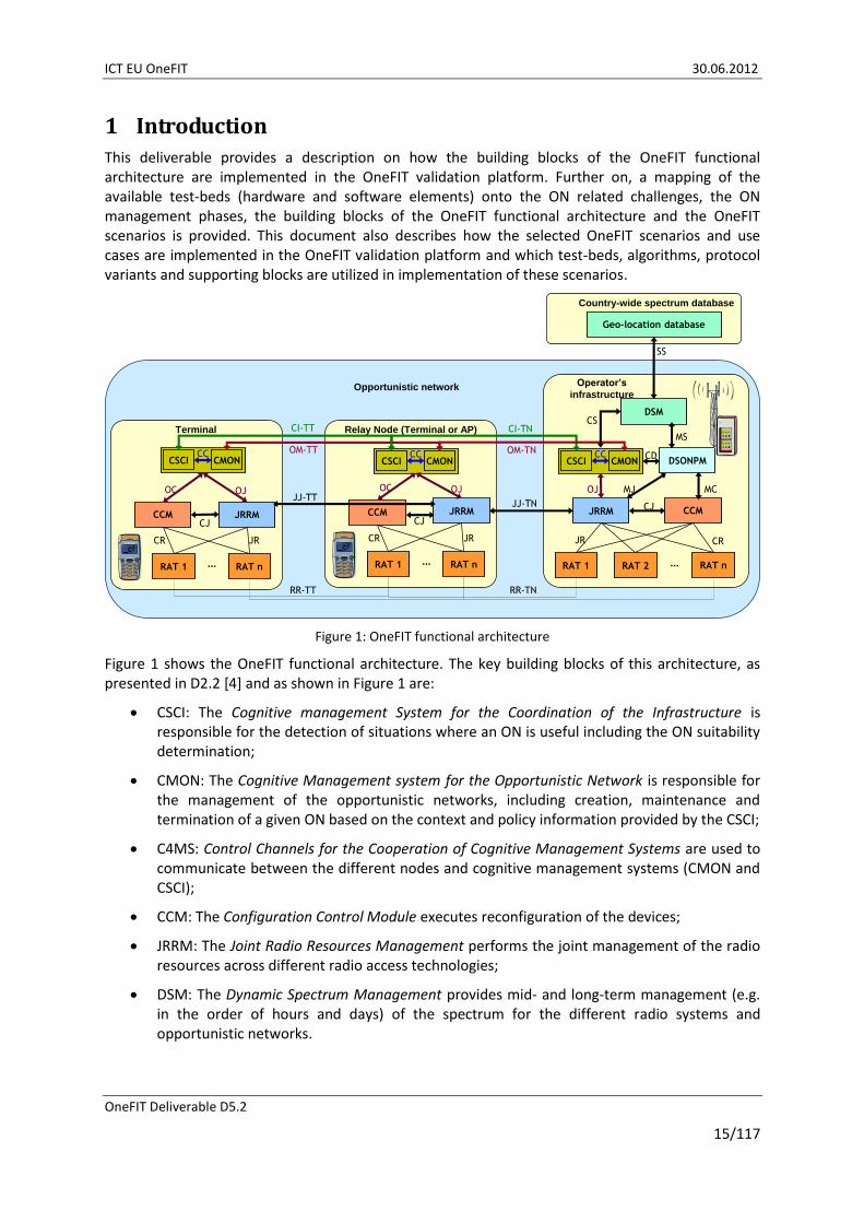
Figure 1 shows the OneFIT functional architecture. The key building blocks of this architecture, as presented in D2.2 [4] and as shown in Figure 1 are:
CSCI: The Cognitive management System for the Coordination of the Infrastructure is responsible for the detection of situations where an ON is useful including the ON suitability determination;
CMON: The Cognitive Management system for the Opportunistic Network is responsible for the management of the opportunistic networks, including creation, maintenance and termination of a given ON based on the context and policy information provided by the CSCI;
C4MS: Control Channels for the Cooperation of Cognitive Management Systems are used to communicate between the different nodes and cognitive management systems (CMON and CSCI);
CCM: The Configuration Control Module executes reconfiguration of the devices;
JRRM: The Joint Radio Resources Management performs the joint management of the radio resources across different radio access technologies;
DSM: The Dynamic Spectrum Management provides mid- and long-term management (e.g. in the order of hours and days) of the spectrum for the different radio systems and opportunistic networks.

ICT EU OneFIT 30.06.2012
OneFIT Deliverable D5.2
16/117
DSONPM: The Dynamic, Self-Organising Network Planning and Management provides mid- and long-term decisions upon the configuration and reconfiguration of the network or parts of it.
The CMON and the CSCI are parts of the OneFIT cognitive management system, which is responsible for decision making regarding ON lifecycle. The cognitive management system supports all of the ON management stages (phases), from suitability determination, through creation and maintenance, to termination. These building blocks, together with the C4MS protocol, represent key elements of the OneFIT system.
The C4MS protocol [6][7], which is implemented as described in section 5, is used on the interfaces between different nodes (See interfaces CI-TT, CI-TN, OM-TT, OM-TN, JJ-TT, JJ-TN, SS in Figure 1). Definition of all interfaces presented in the Figure 1 can be found in [4].
The CCM, JRRM, DSM and DSONPM are supporting blocks in the OneFIT functional architecture, which enable implementation of the OneFIT system into the existing operator’s networks and devices supporting different RATs.
Presented building blocks are implemented into the OneFIT validation platform through their implementation in different test-beds (and combination of test-beds), which comprise the overall validation platform. The WP4 algorithms, which are implemented into the corresponding test-beds, provide different parts of CSCI and CMON systems as well as OneFIT supporting blocks (i.e. DSM). Also, these algorithms address different management phases of opportunistic networks. C4MS protocol variants, which are proposed within [5], are also implemented in test-beds in order to enable the execution of implemented algorithms and to support the ON lifecycle.
Five OneFIT scenarios are defined in D2.1 [3]. The OneFIT architecture is developed in line with requirements set by these scenarios and their use-cases. Also, these scenarios are defined in a way which enables all of the OneFIT advantages and benefits to be showcased. Defined scenarios are (a more detailed description of every scenario and corresponding use-cases can be found in [3]):
Scenario 1: Opportunistic coverage extension;
Scenario 2: Opportunistic capacity extension;
Scenario 3: Infrastructure supported opportunistic device-to-device networking;
Scenario 4: Opportunistic traffic aggregation in the radio access network;
Scenario 5: Opportunistic resource aggregation in the backhaul network.
The rest of the document is organized as follows:
The OneFIT validation platform and test-beds comprising it are described in more detail in section 2;
Implementation of ON management systems (CMON and CSCI) as well as realization of the ON management phases is described in section 3;
Section 4 describes implementation of the OneFIT supporting blocks (JRRM, CCM, DSM and DSONPM);
Section 5 gives description of C4MS implementation;
Practical realization of the OneFIT scenarios 1, 2, 3 and 5 is described in section 6 of this document.

ICT EU OneFIT 30.06.2012
OneFIT Deliverable D5.2
17/117
2 OneFIT validation platform The OneFIT validation platform was introduced in D5.1 [2]. It comprises of hardware (test-beds and equipment) and software (algorithms and protocols) provided by the OneFIT consortium members. Technical characteristics and capabilities of these test-beds are described in D5.1 [2]. Figure 2 provides a high level insight into the architecture of the overall OneFIT validation platform. The OneFIT validation (proof of concept) platform consists of:
ON enabled end user devices including smart-phones, tablets and laptops;
WiFi APs for providing network access to end user devices. ON enabled APs are used for creation of ONs between end user devices and APs as well as ONs between APs.
Femto APs which are used for mimicking macro APs (BSs) as well as for capacity extension by offloading access traffic from macro APs;
ON manager system which comprises of cognitive management elements which are implemented in the core side of the operator’s infrastructure. These ON management entities are implemented on PCs or properly scaled server stations (including databases of contextual parameters used for knowledge derivation).
The overall OneFIT validation platform doesn’t present one physical test-bed, but a collection of different test-beds and OneFIT architecture components provided by different consortium members. These test-beds are utilized in different scenarios, for realization and implementation of different algorithmic approaches and protocol variants.
Figure 2: OneFIT validation platform

ICT EU OneFIT 30.06.2012
OneFIT Deliverable D5.2
18/117
Different components (hardware and software) of the validation platform are provided by different consortium members. Some of these components are stand-alone test-beds used for implementation and validation of specific algorithmic solutions, scenarios/use cases, protocol variants and supporting building blocks. Other components are test-beds and/or architecture elements (i.e. DSM) which can be used for validation and implementation of different algorithmic and protocol solutions as well as realization of different scenarios. Cooperation between different partners’ test-beds already exists in implementation of the OneFIT scenarios (please see section 6 of the deliverable). Also, other possible cooperation opportunities between different test-beds are identified. This cooperation will be further examined in D5.3 (due for December 2012). Detailed description of consortium members’ test-beds and their role within the overall OneFIT validation platform is given later in this section.
Test-beds, which are included into the OneFIT validation platform shown in Figure 2, are mapped onto the ON related challenges (spectrum and nodes&routes selection/identification), the OneFIT scenarios and the ON management phases as shown in Figure 3 and Figure 4. These figures show the potentials of partner’s test-beds. However, they are currently utilized in implementation and validation of specific scenarios on their own or in cooperation (as described in corresponding test-bed descriptions and section 6 of this deliverable).
OneFIT D2.1 [3] has provided a set of system requirements to be fulfilled by the OneFIT system. The complete list of system requirements, with their classification and codes, is given in Table 1. The requirements are mapped to every test-bed description later in this section since implementations performed within these test-beds address specific set of system requirements.
Figure 3: Mapping of the test-beds responsible for spectrum selection/identification challenge onto the OneFIT scenarios and ON management phases
ICT EU OneFIT 30.06.2012
OneFIT Deliverable D5.2
19/117
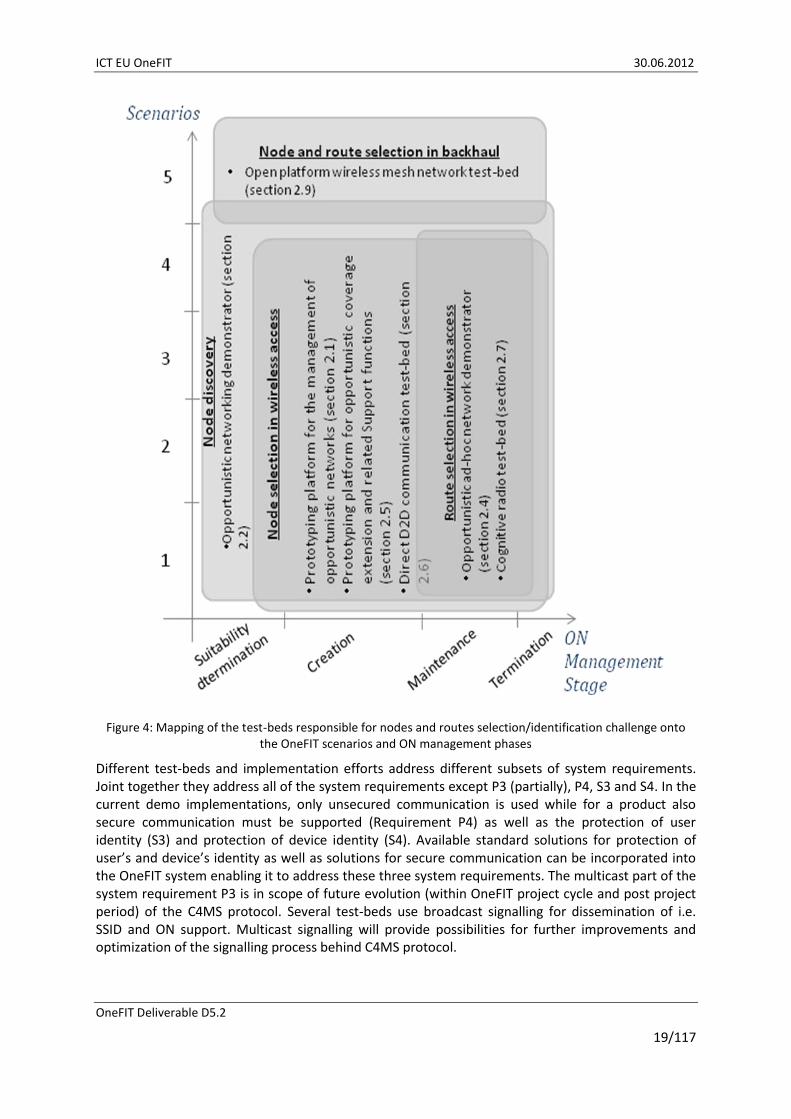
Figure 4: Mapping of the test-beds responsible for nodes and routes selection/identification challenge onto the OneFIT scenarios and ON management phases
Different test-beds and implementation efforts address different subsets of system requirements. Joint together they address all of the system requirements except P3 (partially), P4, S3 and S4. In the current demo implementations, only unsecured communication is used while for a product also secure communication must be supported (Requirement P4) as well as the protection of user identity (S3) and protection of device identity (S4). Available standard solutions for protection of user’s and device’s identity as well as solutions for secure communication can be incorporated into the OneFIT system enabling it to address these three system requirements. The multicast part of the system requirement P3 is in scope of future evolution (within OneFIT project cycle and post project period) of the C4MS protocol. Several test-beds use broadcast signalling for dissemination of i.e. SSID and ON support. Multicast signalling will provide possibilities for further improvements and optimization of the signalling process behind C4MS protocol.

ICT EU OneFIT 30.06.2012
OneFIT Deliverable D5.2
20/117
Table 1: OneFIT system requirements [3][4]
Category Nbr. Title of the requirement
General requirements
G1 Communication with the infrastructure
G2 Communication between terminals
G3 Versatile spectrum use
G4 Versatile RAT/RAN use
G5 Mobility
G6 Relaying
G7 Creation of opportunistic networks
G8 Opportunistic Networks controllable by single operator
G9 Preservation of legacy RAN operation
G10 Compatibility with legacy RAN deployments
G11 Resource efficiency
User and Service related requirements
U1 Hide complexity from the end user
U2 User’s service perception
U3 Availability of ON-related information to the service layer
Opportunistic network Management related requirements
M1 Identification of the need for an opportunistic network
M2 Suitability determination
M3 Creation of opportunistic networks
M4 Connection set-up
M5 Maintenance of opportunistic networks
M6 Release of opportunistic networks
M7 Coordination of opportunistic networks with the infrastructure
M8 Opportunistic network identification
M9 Maximum size of an opportunistic network
M10 Coexistence of opportunistic networks
M11 Assignment of bandwidth
Algorithm related requirements
A1 Context awareness
A2 Decision making
A3 Routing
A4 ON Advertisement
Protocol requirements
P1 Protocol usage
P2 Broadcast/Multicast
P3 Unicast/Dedicated addressing
P4 Secure as well as unsecure communication
P5 Protocol efficiency
Security requirements
S1 Security
S2 Accountability, charging and billing
S3 Protection of user identity
S4 Protection of device identity
2.1 Prototyping platform for the management of opportunistic networks
The prototyping platform for the management of opportunistic networks comprises cognitive management systems and control channels and aims at the efficient application provision through the management of opportunistic networks in coordination with the infrastructure. It has been developed as a Multi Agent System (MAS) based on Java and JADE [16] and it consists of several software and hardware components that can support the execution of a great variety of scenarios and use cases and moreover they are facilitating the integration of new hardware or software

ICT EU OneFIT 30.06.2012
OneFIT Deliverable D5.2
21/117
functionalities that are developed in the context of prototyping activities. Also, as part of the platform a modified version of the Opportunistic Network Environment (ONE) simulator [17] is used. It has been modified accordingly, in order to include also communication with infrastructure and to integrate our developed JADE prototype so as to run capacity extension scenarios. The ONE simulator has been chosen for the experiments due to its inherent capabilities in measuring performance of traditional ONs. It is customizable in terms of traffic generation, mobility of terminals, number of nodes and number of interfaces per node. It is also possible to simulate BS or femtocell entities. Furthermore, the prototyping platform due to the utilization of the JADE middleware which provides distributed functionality can be executed in a distributed way, e.g. the BS CSCI/CMON agents can run on different machines and exchange messages according to the C4MS structure, as it was defined in [7]. In general, JADE components exchange messages which are serialized and transmitted over TCP, according to the FIPA Agent Communication Language (ACL) message structure specification [18].
In the aforementioned platform, both use cases of scenario 2 [3] are implemented, i.e. capacity extension through neighbouring terminals and capacity extension through femtocells, in order to be able to make experiments as part of the proof-of-concept. The implementation comprises the suitability determination phase, the ON creation phase and the termination phase.
The functionalities of the capacity extension through neighbouring terminals algorithm are mapped to the CSCI and CMON as follows:
The context awareness functional block of the CSCI is responsible for acquiring the status of infrastructure elements and the status of terminals;
The decision making mechanism of the CSCI is responsible for the identification of terminals that are located in a congested area and need access to alternate infrastructure elements through neighbouring terminals;
The decision making mechanism of the CMON is responsible for the formation of ON paths for each terminal in the congested area that needs to be redirected to alternate BSs and allocates the terminals to alternate BSs;
The control functional entity of the CMON is responsible for the solution enforcement.
The aforementioned functionalities are depicted in Figure 5.
Furthermore, the functionalities of the selection of nodes algorithms are mapped to the CSCI and CMON as follows:
The context awareness functional block of the CSCI is responsible for acquiring the status of terminals;
The decision making mechanism of the CSCI is responsible for the identification of suitable terminals that will potentially participate in the to-be-created ON;
The decision making mechanism of the CMON is responsible for the selection of terminals that will participate in the ON through the evaluation of terminals’ fitness value;
The control functional entity of the CMON is responsible for the solution enforcement i.e., the selected terminals according to their fitness values will be part of the created ON.
The aforementioned functionalities are depicted in Figure 6.

ICT EU OneFIT 30.06.2012
OneFIT Deliverable D5.2
22/117
JRRM
RAT 1 RAT 2 RAT n…
CCMCJ
JR CR
Operator’s infrastructure
CSCI
Context
Awareness
(status of
infra. netw.
and nodes)
Operator
Policy
Derivation &
Mgmt.
Profile
Management
(user class &
application
requirements
and constraints)
JJ-TNJRRM
DSM
CS
CSCI CMON
OM-TN
Decision Making
ON Suitability
Determination
CC
OJ
CI-TN
CC
RR-TNRAT
CMON
Know-
ledge
Manage-
ment
Decision Making
ON Creation,
Maintenance
&
Termination
Control
Execution of ON
establishment
Execution of ON
reconfiguration
Execution of ON
Termination
Context
Awareness
on status of
QoS and
application
flows
Operator
Policy
Acquisition
Profile
Management
(device
capabilities,
user
preferences)
Knowledge
Management
Result of ON Suitability
procedure, request for
creation of the ON
DSONPM
CD
MS
Identification of terminals that are located in a problematic area (e.g.
congested service area of a BS) and need access to alternated
infrastructure elements through neighboring terminals
• Status of infrastructure elements
• Status of terminals
Decision on what algorithm to run in order to solve the capacity
extension problem
• Management of users’ profiles
• Terminal capabilities (e.g. does the terminal support ON etc.)
Formation of ON paths for each terminal in the congested area
Allocation of terminals from congested BSs to alternate BSs
Solution enforcement
Figure 5 : Mapping of the capacity extension through neighbouring terminals concept to the OneFIT functional architecture
JRRM
RAT 1 RAT 2 RAT n…
CCMCJ
JR CR
Operator’s infrastructure
CSCI
Context
Awareness
(status of
infra. netw.
and nodes)
Operator
Policy
Derivation &
Mgmt.
Profile
Management
(user class &
application
requirements
and constraints)
JJ-TNJRRM
DSM
CS
CSCI CMON
OM-TN
Decision Making
ON Suitability
Determination
CC
OJ
CI-TN
CC
RR-TNRAT
CMON
Know-
ledge
Manage-
ment
Decision Making
ON Creation,
Maintenance
&
Termination
Control
Execution of ON
establishment
Execution of ON
reconfiguration
Execution of ON
Termination
Context
Awareness
on status of
QoS and
application
flows
Operator
Policy
Acquisition
Profile
Management
(device
capabilities,
user
preferences)
Knowledge
Management
Result of ON Suitability
procedure, request for
creation of the ON
DSONPM
CD
MS
Identification of suitable terminals that will
participate in the created ON
Status of terminals
• Selection of terminals that will participate in the ON
• Evaluation of terminals’ fitness value
Solution enforcement-
Selected terminals will create be part
of ONs
Figure 6 : Mapping of the selection of nodes through a fitness value evaluation concept to the OneFIT functional architecture
ICT EU OneFIT 30.06.2012
OneFIT Deliverable D5.2
23/117
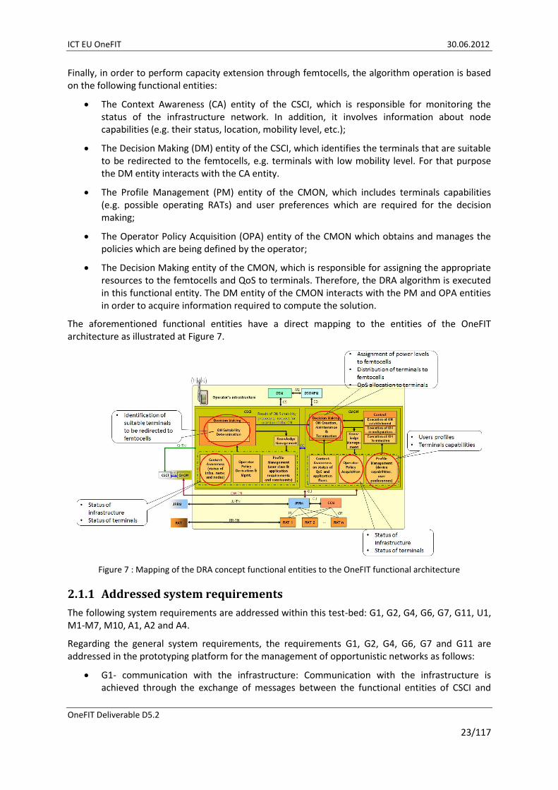
Finally, in order to perform capacity extension through femtocells, the algorithm operation is based on the following functional entities:
The Context Awareness (CA) entity of the CSCI, which is responsible for monitoring the status of the infrastructure network. In addition, it involves information about node capabilities (e.g. their status, location, mobility level, etc.);
The Decision Making (DM) entity of the CSCI, which identifies the terminals that are suitable to be redirected to the femtocells, e.g. terminals with low mobility level. For that purpose the DM entity interacts with the CA entity.
The Profile Management (PM) entity of the CMON, which includes terminals capabilities (e.g. possible operating RATs) and user preferences which are required for the decision making;
The Operator Policy Acquisition (OPA) entity of the CMON which obtains and manages the policies which are being defined by the operator;
The Decision Making entity of the CMON, which is responsible for assigning the appropriate resources to the femtocells and QoS to terminals. Therefore, the DRA algorithm is executed in this functional entity. The DM entity of the CMON interacts with the PM and OPA entities in order to acquire information required to compute the solution.
The aforementioned functional entities have a direct mapping to the entities of the OneFIT architecture as illustrated at Figure 7.
Figure 7 : Mapping of the DRA concept functional entities to the OneFIT functional architecture
2.1.1 Addressed system requirements
The following system requirements are addressed within this test-bed: G1, G2, G4, G6, G7, G11, U1, M1-M7, M10, A1, A2 and A4.
Regarding the general system requirements, the requirements G1, G2, G4, G6, G7 and G11 are addressed in the prototyping platform for the management of opportunistic networks as follows:
G1- communication with the infrastructure: Communication with the infrastructure is achieved through the exchange of messages between the functional entities of CSCI and

ICT EU OneFIT 30.06.2012
OneFIT Deliverable D5.2
24/117
CMON. This is possible through the use of JADE which supports the use of agents which are able to communicate between each other in order to provide the necessary communication with the infrastructure.
G2- communication between terminals: The same communication mechanisms with G1 are also applicable to this requirement as well, in order to provide the necessary communication between terminals;
G4- versatile RAT/RAN use: The platform is RAT-agnostic and specifications of various RATs could be simulated (such as coverage range, bandwidth etc.);
G5- mobility: The platform is based on various mobility models as implemented in the Opportunistic Network Environment (ONE). Indicative mobility models are e.g. Random, Random Waypoint etc.
G6 –relaying: As soon as the ONs are created intermediate nodes in a topology can act as relay nodes;
G7- creation of ONs: The platform has the ability to connect terminals between each other, as long as they are in coverage range, in order to form ONs upon request from the operator (e.g. when congestion of an infrastructure element is observed);
G11- resource efficiency: Through the platform there is the ability to measure the performance of various critical resources such as consumption of energy. It is possible to measure the energy consumption of the infrastructure elements and the various terminals in order to show the gains before and after the solution enforcement.
Regarding the user and service related requirements the U1 is addressed as follows:
U1- hide complexity from the user: All the operations that take place in the platform are not visible to the user, since messages and decisions for the creation of ONs are made automatically. The user will just connect and served through an ON, once the operator deems such an action necessary.
Regarding the ON management related requirements the M1-M7 and M10 are addressed as follows:
M1- identification of the need for an ON: It is possible to initiate the ON suitability determination and creation procedures on a triggered-based basis. This means that the need for an ON can be designated by an operator as soon as congestion of an infrastructure element is sensed or some terminals are left without infrastructure coverage.
M2- suitability determination: Mechanisms of simulating the suitability determination phase are implemented in order to define whether it is possible to create an ON under the current environmental conditions (e.g. are ON-capable terminals in coverage of the problematic ones which are willing to help?);
M3- creation of ONs: Specific algorithms in the context of WP4 have been implemented to the platform in order to proceed to an effective creation of ONs and provide e.g. coverage or capacity extension;
M4- connection set up: The connection set-up mechanisms of the ONE are used in order to connect or disconnect terminals upon request by the operator;
M6 - release of ONs: ONs would be released if the operator designates so, or if the moving terminals move out of coverage between each other, so connection is dropped and the ON is released;

ICT EU OneFIT 30.06.2012
OneFIT Deliverable D5.2
25/117
M7- coordination of ONs with the infrastructure: This requirement is possible in conjunction with the G1 requirement as analyzed previously. To that respect, coordination of terminals (which are part of an ON) with the infrastructure is addressed.
M10- coexistence of ONs: In the platform there is the possibility to create numerous ONs with a variable size (e.g. comprising 2, 3 terminals etc.);
Regarding the algorithm related requirements the A1, A2 and A4 are addressed as follows:
A1- context awareness: Context awareness is obtained through the monitoring of specific parameters such as current location, current mobility level/direction etc. These parameters are measured through the implemented ONE mechanisms.
A2- decision making: Decisions are made according to the implemented algorithms (in the context of WP4) which will designate a solution for the creation of ONs;
A4- ON advertisement: Through the platform, it is possible to show whether a terminal is connected directly to a BS or is served by an ON. To that respect, nearby terminals will know the connection status of another terminal.
2.2 Opportunistic networking demonstrator
The scope of the opportunistic networking demonstrator is to verify the OneFIT scenarios [3], architecture [4], the algorithms for the suitability determination, creation, maintenance and release of opportunistic networks [8] as well as the C4MS protocol [5][6].
This prototype consists of several devices, one or more access points and at least one PC hosting the cognitive radio system management functionality on infrastructure side as shown in Figure 8.
Figure 8: Opportunistic Networking Demonstrator Overview
The most relevant features of this prototype are:
Use of real terminals;
Decisions based on real signal measurements. These measurements are mainly managed by the JRRM as described in section 4.1.
Need for ON occurs due to mobility of users. In the case of the coverage extension scenario, a user moves out of the coverage of the infrastructure.
Suitability determination: Automatic detection of situations where an ON is needed based on the measurements, e.g. degradation of the radio link and handover to another cell is not possible;
ON Creation: Decision to create the ON based on suitability determination;
ICT EU OneFIT 30.06.2012
OneFIT Deliverable D5.2
26/117
Spectrum Selection: DSM decides on which spectrum to use for the relay (as well as for the access points). The implementation of the DSM is described in more detail in section 4.2 where the GUI of the DSM is shown in Figure 54.
Reconfiguration: CSCI/CMON triggered switching on and off of the second radio interface of the relaying device, activation/de-activation of the relaying function;
Mobility procedures: Handover to relay;
Routing: Update of routing tables after handover;
IEEE 802.21 MIH based C4MS implementation.
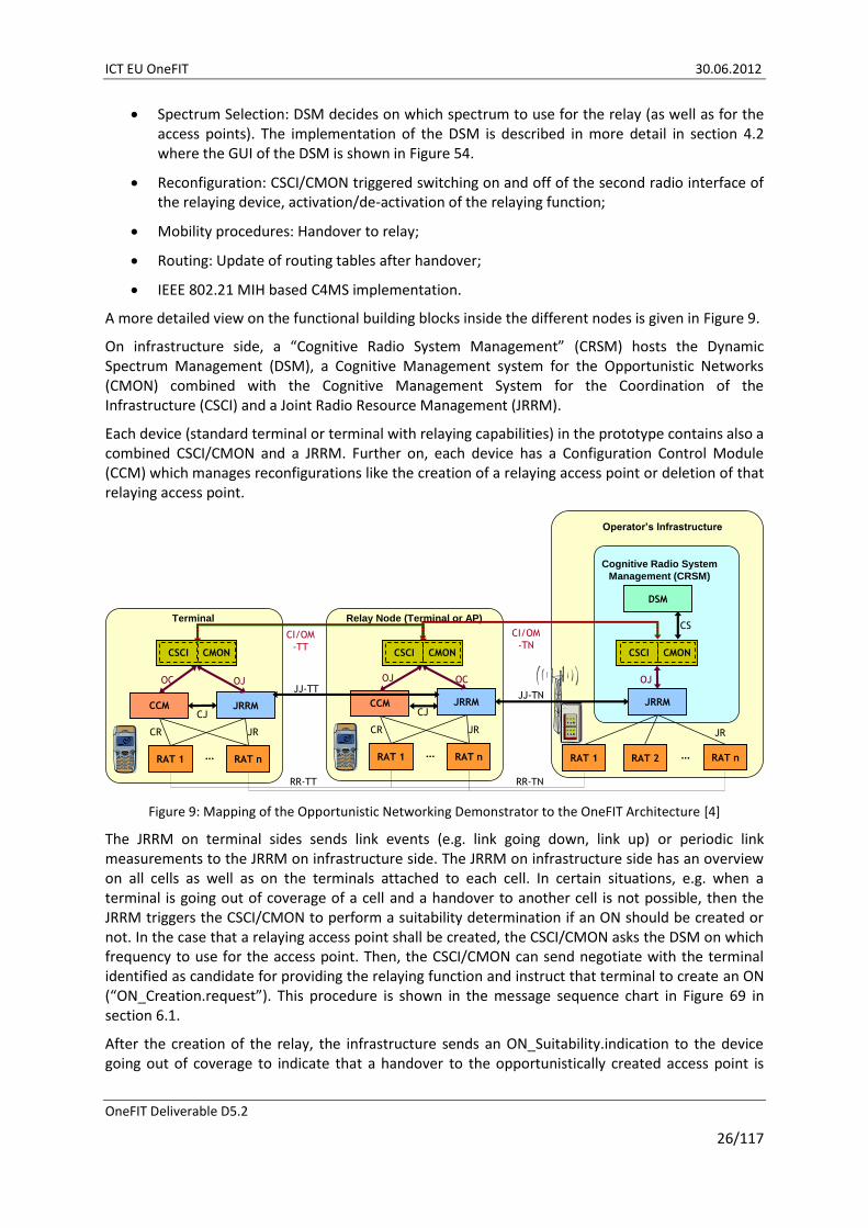
A more detailed view on the functional building blocks inside the different nodes is given in Figure 9.
On infrastructure side, a “Cognitive Radio System Management” (CRSM) hosts the Dynamic Spectrum Management (DSM), a Cognitive Management system for the Opportunistic Networks (CMON) combined with the Cognitive Management System for the Coordination of the Infrastructure (CSCI) and a Joint Radio Resource Management (JRRM).
Each device (standard terminal or terminal with relaying capabilities) in the prototype contains also a combined CSCI/CMON and a JRRM. Further on, each device has a Configuration Control Module (CCM) which manages reconfigurations like the creation of a relaying access point or deletion of that relaying access point.
JRRM
RAT 1 RAT 2 RAT n…
DSM
JR
CS
Operator’s Infrastructure
JRRM
RAT 1 RAT n…
CCMCJ
CR JR
Relay Node (Terminal or AP)
JJ-TN
OJ
CI/OM
-TN
JRRM
RAT 1 RAT n…
CCMCJ
CR JR
Terminal
CI/OM
-TT
OCOJOJOCJJ-TT
CSCI CMON CSCI CMON CSCI CMON
RR-TT RR-TN
Cognitive Radio System
Management (CRSM)
Figure 9: Mapping of the Opportunistic Networking Demonstrator to the OneFIT Architecture [4]
The JRRM on terminal sides sends link events (e.g. link going down, link up) or periodic link measurements to the JRRM on infrastructure side. The JRRM on infrastructure side has an overview on all cells as well as on the terminals attached to each cell. In certain situations, e.g. when a terminal is going out of coverage of a cell and a handover to another cell is not possible, then the JRRM triggers the CSCI/CMON to perform a suitability determination if an ON should be created or not. In the case that a relaying access point shall be created, the CSCI/CMON asks the DSM on which frequency to use for the access point. Then, the CSCI/CMON can send negotiate with the terminal identified as candidate for providing the relaying function and instruct that terminal to create an ON (“ON_Creation.request”). This procedure is shown in the message sequence chart in Figure 69 in section 6.1.
After the creation of the relay, the infrastructure sends an ON_Suitability.indication to the device going out of coverage to indicate that a handover to the opportunistically created access point is

ICT EU OneFIT 30.06.2012
OneFIT Deliverable D5.2
27/117
recommended. After performing a handover, the device going out of coverage is then connected via a relaying terminal to the infrastructure and the going out-of-coverage problem is solved by the coverage extension provided by the relay.
2.2.1 Addressed system requirements
The following system requirements, as presented in Table 1, are addressed within this test-bed: G1-G11, U1-U2, M1-M9, M11, A1-A3, P1, P3, P5 and S2.
The prototype used an 802.21 based C4MS (P1, P3, P5 and S2) implementation for the communication between the different nodes in the infrastructure and the devices (G1 and G2) and uses different radio access technologies (G4) like WLAN and Bluetooth. The DSM decides on which spectrum to use (G5) for the relay (G6) when creating the opportunistic network (G6 and G7). Handovers (G5) are executed to connect directly to the infrastructure (G9, G10 and G11) and with the ON. The opportunistic network management (M1-M9, M11 and A1-A3) has been implemented in a distributed way where parts of the functions are located on infrastructure side and others are located inside the devices.
2.3 Opportunistic service provision demonstrator
This demonstrator evaluates the feasibility of building novel end-user services that take advantage of the underlying Opportunistic Network capabilities of both infrastructure and user terminals. The ability to offer such opportunistically-supported services presents a great potential for MNOs to develop new business models to capitalize the investment in the deployment of ON mechanisms.
Therefore, this demonstration does not aim to evaluate the performance of ON procedures and algorithms. Instead, it is assumed that OneFIT mechanisms work, so that an end-user application can be built upon them; after that, service-oriented aspects such as the reliability (the ON is seamlessly handled as the nodes exit and enter in it), the resilience (the service is alive during the lifetime of the ON) or the scalability (the service accepts a growing number of nodes) of the available tools will be assessed.
In particular, according to the use case to be demonstrated (see section 6.3.2 for a detailed description), a high-mobility scenario, where a significant number of nodes enter and exit the ON while it is alive, is depicted. A performance assessment on such scenario could not be performed on the OneFIT validation platform, so a specific test-bed that emulates the behaviour of the wireless network and the OneFIT mechanisms has been developed.
This test-bed is based on a vehicle traffic simulator that uses real cartography with an OneFIT abstraction layer deployed over it. The selected traffic simulator tool is SUMO (Simulation of Urban Mobility [13]), an open-source project able to simulate large traffic sets of vehicles and their behaviour over the time in a realistic way. The simulation is therefore split into two different layers: the traffic simulation layer that obtains the position of vehicles and their behaviour over the time and the network simulation layer that evaluates the performance of the ON established over them.
In the test-bed’s ONs, mobile nodes are assumed to be the simulated vehicles, which move throughout city streets following certain traffic rules (that depend on the city features, the hour of the day, etc.) Fixed infrastructure nodes are located in defined positions and they mimic the features of real 3G base stations. According to the OneFIT architecture and procedures, an ON is created among one or more mobile nodes and one or more infrastructure nodes. For each ON, the infrastructure selects one of the vehicles as a ‘network controller’, according to a specified criterion (such as the one with more available resources, the best SINR or any other). This node will act as a gateway between the rest of the mobile nodes in the ON and the infrastructure node. Thus, the

ICT EU OneFIT 30.06.2012
OneFIT Deliverable D5.2
28/117
controller will collect all the logs from the surrounding vehicles and send them to the monitoring server. Figure 10 depicts this communication structure.
Figure 10: Simulated scenario
The network emulation block is the part of the test-bed that mimics the behaviour of the wireless network and the OneFIT mechanisms. In particular, an abstraction layer that simulates the behaviour of the OneFIT-based vehicle-to-vehicle communications has been developed. It consists of a simplified model of the OneFIT procedures that hides the underlying complexity (C4MS protocol stack and specific algorithms). This abstraction layer thus implements the ON management phases in a simplified way: candidate nodes are selected during Suitability Phase; connections will be established during the Creation Phase using a very basic routing scheme; during the Maintenance Phase, nodes entering and exiting the ON will be controlled; and Termination Phase will consist of dissolving the connections.
The implementation of this abstraction layer needs two kinds of nodes to be defined:
OneFitNodes are generic ON-capable nodes. They implement a set of functions called OneFitNodeRules.
OneFitcontrollers are nodes with the additional functionalities to act as gateway for the rest of nodes in the ON.
Additionally, an entity called OneFitNet has been defined to represent the ON created among several OneFitNodes and OneFitcontrollers. These entities implement a similar set of functions called OneFitNetRules to account for the OneFIT mechanisms. Figure 11 shows the relationship between these elements.
There is also a Network Control Layer that implements the rules and policies. These rules define the OneFITNodes and establish logical links between them. The resulting network structures compose the ONs according to radio conditions. Those logical links will be continuously updated as some OneFitNodes leave the ON and new ones join.

ICT EU OneFIT 30.06.2012
OneFIT Deliverable D5.2
29/117
Figure 11: Relationship between simulator entities
Finally, Figure 12 depicts the components of the control system architecture and the data flows among them. The control system is composed by four modules:
SUMO-IFACE is responsible for the translation of the system information to Java format, sending and receiving data to/from SUMO;
SIM-ENGINE controls the rest of modules, monitors system status and invokes the correct functions;
CAR-CONTROLLER monitors the state of all simulated nodes;
GUI-ENGINE is responsible of collecting data and managing user interaction.
Figure 12: System control structure and data-flow
During the simulation, the data flows between entities proceed in the following way: SIM-ENGINE orders SUMO-IFACE to request a new iteration (1). SUMO-IFACE performs the request (2), receives the answer (3), translates it and redirects it to SIM-ENGINE (4). SIM-ENGINE notifies the changes to CAR-CONTROLLER (5), who updates its data structures and returns the control SIM-ENGINE (6). SIM-ENGINE orders GUI-ENGINE to refresh (7), so GUI-ENGINE has to request vehicle information to CAR-CONTROLLER (8), CAR-CONTROLLER returns the information (9) and finally GUI-ENGINE draws in the screen the status of the new iteration (10).

ICT EU OneFIT 30.06.2012
OneFIT Deliverable D5.2
30/117
The test-bed includes also a Graphical User Interface (GUI) that manages the process of scenario setup (based on real cartography layouts). It also allows selecting different vehicle densities according to daytime, season of the year or even hazardous situations that may modify traffic flow. The wireless capabilities of simulated vehicles (WiFi, Bluetooth and UMTS) can also be configured. Once the simulation is configured, the GUI launches the SUMO simulator and collects vehicle data. For each simulated vehicle, the application gathers position coordinates current speed and additional data such as fuel consumption, noise generation or polluting gasses emissions (CO, CO2, NOx…). This information can be displayed and is also processed to obtain the KPIs that may trigger the creation of an ON. Figure 13 depicts a view of the graphic interface, where real cartography is used and simulated vehicles (white and grey dots) move through the city cartography according to the established rules. This image illustrates the complexity of the application, where dozens of mobile nodes will be monitored as they become part of one or more ONs.
Figure 13: GUI screenshot (1)
Figure 14 shows a different display of the GUI that shows the network topology when an ON has been created among an infrastructure node (Central Square) and five vehicles (circles). Wireless links have been created between pairs of vehicles (white thin lines), but only the controller node (bottom circle) is linked to the infrastructure (green line). The statistical data showed on the left side are retrieved from the highlighted node (the circle under the pointer).
Figure 14: GUI screenshot (2)

ICT EU OneFIT 30.06.2012
OneFIT Deliverable D5.2
31/117
2.3.1 Addressed system requirements
The following system requirements are addressed within this test-bed: G1, G2, G4-G7, G9-G10, U1-U3, M1-M7, M10 and A1-A2.
Regarding the general system requirements, the following requirements are addressed:
G1 – Communication with infrastructure: Some of the terminals are UMTS-enabled, so they are able to communicate with the infrastructure nodes via UMTS RAN;
G2 – Communication between terminals: Terminals communicate to each other via ad-hoc short-range RATs, such as WiFi and Bluetooth;
G4 – Versatile RAT/RAN: ONs include terminals capable of using different RATs to communicate (namely, UMTS, WiFi and Bluetooth);
G5 - Mobility: Terminals are constantly moving around the scenario, following some simple mobility rules defined in the SUMO simulator;
G6 – Relaying: Report and context data from non-UMTS terminals are relayed towards infrastructure via UMTS-enabled terminals;
G7 - Creation of opportunistic networks: Infrastructure negotiates with terminals the creation of ONs;
G9 – Preservation of legacy RAN operation: Infrastructure network behaviour remains unaffected by the presence of ONs;
G10 – Compatibility with legacy RAN deployments: ON operation does not interfere with current infrastructure RAN deployment.
Regarding the user and service related requirements the following requirements are addressed:
U1 – Hide complexity from the end user: There is no intervention of final service users in the creation of ONs;
U2 – User’s service perception: The existence of ONs causes no effect on the service perception by end users;
U3 - Availability of ON-related information to the service layer: The service under test receives information about the existence of ONs and the nodes that are part of them.
Regarding the ON management related requirements the following requirements are addressed:
M1 - Identification of the need for an opportunistic network: The service under study has a triggering mechanism (based on pollution measures) to detect the need of an ON. When this need is detected, the service asks the infrastructure nodes for the creation of the ON.
M2 - Suitability determination: Infrastructure selects the most suitable terminal nodes to be part of the ONs, based on context data previously gathered;
M3 - Creation of opportunistic networks: Infrastructure negotiates with terminals the creation of ONs;
M4 - Connection set-up: UMTS-enabled terminals are able to establish a connection with the infrastructure nodes;
M5 - Maintenance of opportunistic networks: Infrastructure is constantly aware of the status of the ONs, allowing the entrance and the exit of terminal nodes as they move, and reconfiguring the relaying routes from non-UMTS terminals to UMTS-enabled terminals;

ICT EU OneFIT 30.06.2012
OneFIT Deliverable D5.2
32/117
M6 - Release of opportunistic networks: The service under study has a triggering mechanism (based on pollution measures) to detect when ONs are no longer needed. When this is detected, the service asks the infrastructure nodes for the termination of the ON.
M7 - Coordination of opportunistic networks with the infrastructure: The service under study runs on both ON and infrastructure nodes;
M10 - Coexistence of opportunistic networks: Several ON can be present simultaneously in the scenario, as several instances of the service under study can run independently.
Regarding the algorithm related requirements the following requirements are addressed:
A1 - Context awareness: The infrastructure nodes are able to retrieve information about terminals (capabilities, status and propagation) that are used to create, reconfigure and terminate ONs;
A2 - Decision making: The infrastructure is able to make the decision of creating, reconfiguring and terminating an ON based on context data.
2.4 Opportunistic ad-hoc network routing demonstration
The prototyping platform for the realisation of the opportunistic ad-hoc network routing demonstrator is composed of 4 laptops, using Linux as operating system, and communicating between themselves through the WiFi protocol (802.11). The scope is to verify the route pattern selection algorithm as well as the multi-flow route co-determination algorithm. The platform uses a standard WiFi Device driver, which has been modified in order to emulate a multi-hop topology: filtering of the received MAC PDUs has been added in the Wi-Fi Interface adaptation module. On every node a configuration file, containing the list of available neighbours (from WiFi driver point of view) is created.
The environment is configured to get a multi-hop topology and a multi-route possibility to transmit the data.
Figure 15: Opportunistic ad-hoc network routing platform
The demonstration is related to the network coverage extension; it is not intended to connect neither an access point nor a base station to simulate the infrastructure. In the ad hoc cloud, the node connected to the infrastructure gets a particular behaviour and acts as a gateway.

ICT EU OneFIT 30.06.2012
OneFIT Deliverable D5.2
33/117
The purpose of demonstration is to apply OneFIT routing algorithms by generating different traffic flows between the nodes UE1 and UE2 (Figure 15).
This environment allows using most of existing user applications (for example data streaming (VLC player application), voice over IP (SIP), file downloading (FTP), etc). The implemented software is developed using the concepts of virtual NIC (Network Interface Controller) to allow any standard user’s application to be executed.
Figure 16 depicts the detailed architecture implementation of the demonstration.
User applications
OneFit algorithms
OneFit adaptorto Radio NIC
Linux Wifi NIC
OneFit V-NIC
RAT interface
Linux extension V-NIC (Virtual
Network interface Controller)
Allow any standard user application :
VLC, PING, FTP…
Allow ON management:
C4MS messaging …
Adaptation to standardize access to
RAT
Network coding and Route pattern
selection algorithms
Figure 16: Test-bed software architecture
The “OneFIT V-NIC” module contains one of two OneFIT routing algorithms: Either the route pattern selection algorithm or the multi-flow route co-determination algorithm. Both algorithms are triggered for any IP packet handling. The algorithm controls the transmission of the packet over the air through the Wi-Fi protocol (IEEE 802.11) configured in ad-hoc mode.
2.4.1 Addressed system requirements
The requirements met by the Thales demonstrator are Communication between terminals (G2), Relaying (G6), Resource efficiency (G11), Maintenance of the ad-hoc part of the opportunistic network (M5), Context awareness (A1), Decision making (A2) and Routing (A3).
2.5 Prototyping platform for opportunistic coverage extension and related support functions
The Prototyping Platform for Opportunistic Coverage Extension and related Support Functions is addressing the following key features:
Opportunistic Network Support, i.e. Coverage Extension is achieved by selected Mobile Devices acting as Relay Nodes;
Best Connection, i.e. in a Coverage Extension context, the most suitable link among a set of available heterogeneous link technologies (WLAN, 3G, etc.) is identified and selected;
Multi-Homing Support, i.e. a stream is split over two links of distinct Radio Access Technology.
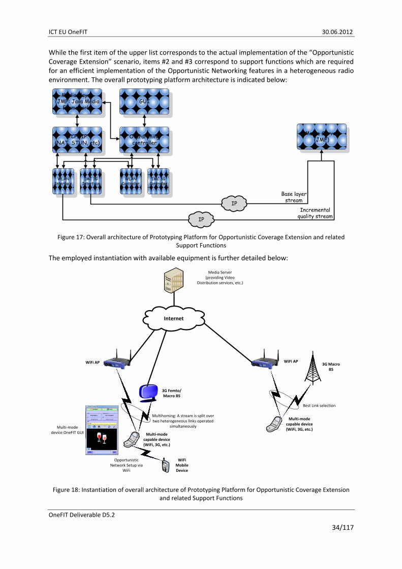
ICT EU OneFIT 30.06.2012
OneFIT Deliverable D5.2
34/117
While the first item of the upper list corresponds to the actual implementation of the “Opportunistic Coverage Extension” scenario, items #2 and #3 correspond to support functions which are required for an efficient implementation of the Opportunistic Networking features in a heterogeneous radio environment. The overall prototyping platform architecture is indicated below:
Media Player(JMF: Java Media
Framework)GUI
TCP/ IP(NAT, STUN, etc)
WLAN Interface
IMC 3G Interface
Overarching controller
WLAN Controller
IMC 3G Controller
Media Server(JMF)
Incremental quality stream
Base layer stream
IP
IP
Figure 17: Overall architecture of Prototyping Platform for Opportunistic Coverage Extension and related Support Functions
The employed instantiation with available equipment is further detailed below:
Media Server(providing Video
Distribution services, etc.)
Internet
WiFi AP WiFi AP
WiFi Mobile Device
3G Femto/Macro BS
Multi-mode capable device (WiFi, 3G, etc.)
Opportunistic Network Setup via
WiFi
Multihoming: A stream is split over two heterogeneous links operated
simultaneously
Multi-mode capable device (WiFi, 3G, etc.)
3G Macro BS
Best Link selection
Multi-mode device OneFIT GUI
Figure 18: Instantiation of overall architecture of Prototyping Platform for Opportunistic Coverage Extension and related Support Functions

ICT EU OneFIT 30.06.2012
OneFIT Deliverable D5.2
35/117
As it will be further detailed in section 6.1, the Prototyping Platform for Opportunistic Coverage Extension and related Support Functions is built such that it can be suitably reconfigured to the following configurations:
Provision of wireless services in a dense neighbourhood environment building on non interfering Radio Access Technology;
Provision of wireless services in a dense neighbourhood environment employing an Opportunistic Network for ensuring access for a WiFi-only Terminal Device;
Provision of wireless services in a dense neighbourhood environment employing automized network reconfiguration and an Opportunistic Network for ensuring access for a WiFi-only Terminal Device;
Provision of wireless services in a dense neighbourhood environment employing Multi-Homing.
For this test-bed, a Graphical User Interface (GUI) has been developed with the following key features:
i. Illustration of the multitude of wireless links being maintained simultaneously:
Figure 19: GUI indicating active wireless links and related key parameters
ii. Illustration of test-bed configuration to be operated:

ICT EU OneFIT 30.06.2012
OneFIT Deliverable D5.2
36/117
Figure 20: GUI indicating test-bed configuration to be operated
iii. Illustration of Operator policies to be imposed onto Mobile Device centric link selection:
Figure 21: GUI indicating operator policies to be met by mobile device decision making entities
iv. Illustration of GUI showing live video-streaming:

ICT EU OneFIT 30.06.2012
OneFIT Deliverable D5.2
37/117
Figure 22: GUI showing live video streaming
2.5.1 Addressed system requirements
The following system requirements are addressed within this test-bed: G1, G4, G6, G7, G9-G11, U1, M1-M7 and A1-A3.
From the group of general system requirements, the requirements G1, G4, G6, G7 and G9-G11 are addressed as follows in the prototyping platform for opportunistic coverage extension and related support functions:
G1 - Communication with the infrastructure: The platform provides access to cellular Macro/Femto Base Stations, WiFi Access Points, etc;
G4 - Versatile RAT/RAN use: The choice of Radio Access Technologies is updated depending on the interference/congestion context (e.g., avoid congested Radio Access Technologies). Also, Radio Access Technologies are operated simultaneously;
G6 – Relaying and G7 - Creation of opportunistic networks: are implemented in the sense that a mobile relay node is initiated for providing access to other devices, which may be out of coverage of the concerned Macro/Femto Base Station, which may not support/prefer 3G at the given point in time, etc;
G9 - Preservation of legacy RAN operation and G10 - Compatibility with legacy RAN deployments: the whole test-bed builds on the usage of legacy RAN; all new features are transparent to the RAN and therefore full compatibility with legacy RANs is achieved;
G11 - Resource efficiency: is mainly addressed in the context of best link selection, i.e. resource efficiency is maximized by selecting the most suitable Radio Access Technology.
From the group of user and service related requirements, the requirement U1 is addressed as follows in the prototyping platform for opportunistic coverage extension and related support functions:

ICT EU OneFIT 30.06.2012
OneFIT Deliverable D5.2
38/117
U1 - Hide complexity from the end user: The platform performs RAT selection without any User Interaction.
From the group of opportunistic network management related requirements, the requirements M1-7 are addressed as follows in the prototyping platform for opportunistic coverage extension and related support functions:
M1-7 (Identification of the need for an opportunistic network, Suitability determination, Creation of opportunistic networks, Connection set-up, Maintenance of opportunistic networks, Release of opportunistic networks, Coordination of opportunistic networks with the infrastructure): The platform performs the management of opportunistic networks going through the main phases (suitability determination, creation, maintenance, termination). Connection set-up is managed on a per-need basis, e.g. an opportunistic network may only be exploited if other links are unsuitable due to congestion events.
From the group of algorithm related requirements, the requirements A1-3 are addressed as follows in the prototyping platform for opportunistic coverage extension and related support functions:
A1 - Context awareness and A2 Decision making: The platform observes for example congestion events, the availability of multiple heterogeneous RATs to be used simultaneously, etc. and takes corresponding context information for decision making on RAT selection into account;
A3 - Routing: The platform decides on traffic routing in case that several heterogeneous Radio Access Technologies are operated simultaneously.
2.6 Direct D2D communication test-bed
The objective of the prototype platform is to demonstrate the realization of suitability determination, creation, maintenance and termination of Opportunistic Networks between 2 devices located in proximity by establishing direct device 2 device communications. The prototype is addressing scenario 3 but can be enhanced in future steps to support other scenario (e.g. scenario 2 for coverage extension).
The prototype implements the following CMON functionalities as described in D2.2 [4]:
Control mutual discovery of nodes (devices);
obtains context and policy information from the CSCI (QoS requirements);
Commands for managing the ON operational phases (e.g., ON establishment, maintenance/ reconfiguration and termination procedures);
Obtain local context information: measurements from devices, geo-location coordinates from device built-in positioning functions;
Control terminal reconfiguration capabilities (radio link and network layer);
Control over the establishment/modification/release of bearer services in the infrastructure network to support ON traffic;
Establish security on ON links.
This demonstrator consists of several devices, which have the capabilities to support several Radio Access Technologies (RAT), and are, on their initial connection, connected to the infrastructure via 3GPP UTRAN radio access.
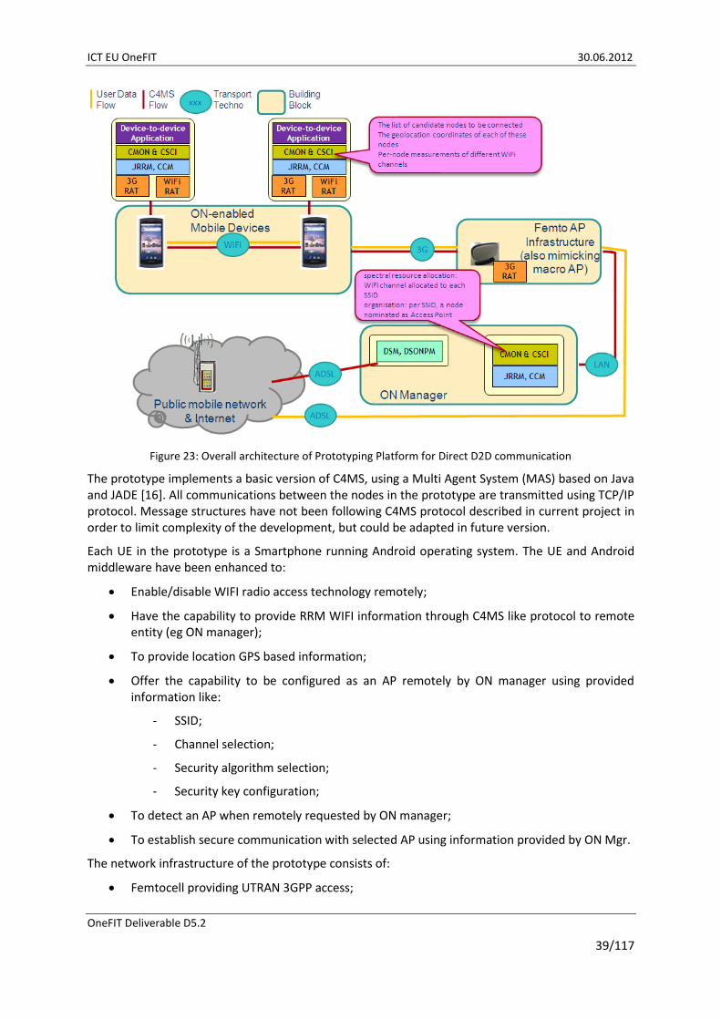
ICT EU OneFIT 30.06.2012
OneFIT Deliverable D5.2
39/117
Figure 23: Overall architecture of Prototyping Platform for Direct D2D communication
The prototype implements a basic version of C4MS, using a Multi Agent System (MAS) based on Java and JADE [16]. All communications between the nodes in the prototype are transmitted using TCP/IP protocol. Message structures have not been following C4MS protocol described in current project in order to limit complexity of the development, but could be adapted in future version.
Each UE in the prototype is a Smartphone running Android operating system. The UE and Android middleware have been enhanced to:
Enable/disable WIFI radio access technology remotely;
Have the capability to provide RRM WIFI information through C4MS like protocol to remote entity (eg ON manager);
To provide location GPS based information;
Offer the capability to be configured as an AP remotely by ON manager using provided information like:
- SSID;
- Channel selection;
- Security algorithm selection;
- Security key configuration;
To detect an AP when remotely requested by ON manager;
To establish secure communication with selected AP using information provided by ON Mgr.
The network infrastructure of the prototype consists of:
Femtocell providing UTRAN 3GPP access;

ICT EU OneFIT 30.06.2012
OneFIT Deliverable D5.2
40/117
ON mgr consisting of a server on which ON algorithm is executed;
Asterisk server to provider CS domain service;
Apache server providing HTTP service in the network, including web browsing service and HTPP video streaming function;
DHCP server providing IP address to the different network entities (e.g. femtocell);
PC running Wireshark to perform maintenance and monitor IP traffic between the different nodes of the network infrastructure.
The algorithm running on the ON mgr server allows based on information requested/reported to/by the devices attached within the UTRAN network to determine the opportunity of direct Device to Device communication.
Figure 24: Infrastructure use in the demonstrator
When UE registers in the 3GPP network via UTRAN, they also provide registration information to the ON manager who configures UEs in order to gather adequate information to determine D2D communication opportunity.
In case UE2 is a video streaming server and UE1 wants to play a video available on UE2 (Requesting accessing the video from a server) then ON manager is responsible to determine if UE1, UE2 are close to each other and if the radio condition are met to establish D2D communication. To perform this task, ON Manager checks for the suitability of creating a LAN (i.e. geographical position, 3GPP radio cell and radio measurements). If ON Mgr determines that the initial condition are favourable then ON mgr initiates Wi-Fi discovery algorithm, controlling each UE’s procedure and retrieves the discovery results from the UE1, UE2. ON Mgr selects the UE which will act as WiFi-Access Point (Group Owner) in the WLAN to be formed and selects the optimal configuration for the WLAN and informs it to the UE (Role assignment, identities (SSID) and Security information). Then UE1 and UE2

ICT EU OneFIT 30.06.2012
OneFIT Deliverable D5.2
41/117
perform necessary WLAN procedure accordingly to establish trusted paths and allow UE2 to start streaming from UE1 content (exchanging user data over the WLAN).
2.6.1 Addressed system requirements
The following system requirements are addressed within this test-bed: G1-G3, G7, G9G10, U1, M1, M3, M4, M8, A1, A2, P1, P3 and S1.
From the group of general requirements the following ones are addressed:
G1 – Communication with the infrastructure: The test-bed includes a femto Access Point that emulates the behaviour of the infrastructure in charge of controlling the ON. The C4MS messages are transferred between the terminals and the ON Manager (infra CSCI/CMON) through the femto AP.
G2 – Communication between terminals: The test-bed includes a link between the two or more terminals using a 802.11 WLAN;
G3 – Versatile spectrum use: The test-bed performs a dynamic spectrum assignment, after having identified the optimal 802.1 channel to be used;
G7 – Creation of opportunistic networks: The test-bed allows the creation of an ON by setting a WLAN between terminals under the control of the cellular network (ON Manager);
G9/G10 – Preservation of legacy RAN operation/Compatibility with legacy RAN deployments: The test-bed implements an “over-the-top” solution for C4MS which is compatible with current 3GPP RAN in terms of operation and deployment.
From the group of user and service related requirements, the following ones are addressed by the test-bed:
U1 – Hide complexity from the end user: the test-bed allows the setup of the ON to be fully transparent to the user. Typically the setup of the relay is completely hidden from the user, being just a part of the video connection establishment.
From the group of opportunistic network management related requirements, the following ones are addressed by the test-bed:
M1 - Identification of the need for an opportunistic network: The test-bed allows for application-triggered identification of the need;
M3 – Creation of opportunistic networks: The test-bed implements the ON creation stage;
M4 – Connection setup: The test-bed provides means for the ON Manager to trigger and control the establishment of WLAN connections between terminals;
M8 – Opportunistic Network identification: the test-bed re-use the SSID concept and parameter of 802.11 as a means to identify a given ON.
From the group of algorithms related requirements, the test-bed addresses the following ones:
A1 – Context awareness: The test-bed implements context awareness in the field of 802.11 channel occupation;
A2 – Decision making: The test-bed implements decision making for the decision to build the ON (application trigger) and optimal setting of the underlying WLAN.
From the group of Protocols related requirements, the test-bed addresses the following ones:

ICT EU OneFIT 30.06.2012
OneFIT Deliverable D5.2
42/117
P1 – Protocol Usage: The test-bed implements a basic subset of C4MS messages, enriched with WLAN specific parameters, over an agent-based application-level protocol;
P3 - Unicast/Dedicated addressing: The JADE protocol allows allocation of dedicated addresses/identifiers for unicast exchanges.
From the group of Security related requirements, the test-bed addresses the following ones:
S1 – Security: the test-bed allows the setup of a secure WLAN for the ON, using any legacy WLAN security techniques.
2.7 Cognitive radio test-bed
The demonstration of the QoS and spectrum aware routing algorithm is performed based on a test-bed comprising “Wireless open-Access Research Platform” (WARP) [21] boards. All nodes use wireless 802.11 standards and are loaded with Optimized Link State Routing (OLSR) [22]-based Spectrum-aware routing protocol. Demonstration will address routing/re-routing upon changes in spectrum opportunity availability within OneFIT scenarios 1 & 2. C4MS signalling is not implemented as the focus of demonstration is on performance of modified OLSR (spectrum-awareness). Demonstration platform includes:
Network of 5 ad-hoc radio nodes (WARP boards), with WiFi connections;
All boards have multi-radio capability;
2 laptops acting as sink/source for streaming application;
One “control” laptop + router.
It is assumed that the network (operator governed) has completed the neighbour discovery (responsibility of L1) and suitability determination phases. The proposed algorithm covers the routing table setup and maintenance phases (as required during ON creation/re-configuration phases). During creation phase, standard OLSR is used with hop-count as the metric. The primary scenarios of interest relate to ON coverage extension as depicted in Figure 25 and Figure 26 below.
Coverage of the Infrastructure
Opportunistic Network
(ON)
UE#1 is out
of direct
coverageUE #2
Macro BS#1
UE #3 UE #4
Operator
Infrastructure
Backbone
Flow
Data
Flow
C4MS
Flow
Streaming
Video / Traffic
SOURCE
Streaming
Video / Traffic
SINK
WARP
Control commands /
measurements
Switch/router
NW control
WARPLab User
M-code
JRRM, CCM
RAT #2 RAT #1
CMON & CSCI
JRRM, CCM
RAT #1 RAT #2
CMON & CSCI
JRRM, CCM
RAT #2 RAT #1
CMON & CSCI
JRRM, CCM
RAT #1 RAT #2
CMON & CSCIJRRM, CCM
RAT #1
DSM
CMON & CSCI
Figure 25: ON “coverage extension” Scenario 1a – “Relaying” within infrastructure coverage

ICT EU OneFIT 30.06.2012
OneFIT Deliverable D5.2
43/117
Scenario 1a involves the following main steps:
The terminal (UE #1) is out of coverage of infrastructure i.e. Macro BS #1;
Following neighbour discovery, candidate node identification and suitability determination phase, the initial path is established between UE #1 and BS #1 via UE #2, #3, #4 (acting as relays), and ON is created;
UE #3 will be moved (or powered down to emulate loss of connectivity) so it is no longer within BS #1 coverage thus reconfiguration phase is initiated;
To demo the robustness and adaptability of the prototype implementation under a varying network topology, the ability of MAC and routing protocols to adapt to link breaks caused by topology changes will be shown while the end-user application is running on the laptops connected to SORURCE/SINK WARP boards). The end-user application is video streaming executed over multiple hops. Routing protocol implementation is considered part of CMON module/functionality.
During Maintenance/Reconfiguration phase, the routing protocol will update the original path (UE#1, #2, #3, #4, BS#1) to the new path (UE#1, #2, #4, BS#1);
UE #4 will then be moved (or powered down to emulate loss of connectivity) so it is no longer within BS #1 coverage thus reconfiguration phase is triggered once again;
The routing protocol will update the current path (UE#1, #2, #4, BS#1) to the new path (UE#1, #2, #3, BS#1);
As reconfiguration takes place it is expected that the routing algorithm will be able to maintain the quality of the application running on the two end laptops.
Coverage of the Infrastructure
Opportunistic Network
(ON)
UE#1 is out
of direct
coverageUE #2
Macro BS#1
UE #3 UE #4
Operator
Infrastructure
Backbone
Flow
Data
Flow
C4MS
Flow
Streaming
Video / Traffic
SOURCE
Streaming
Video / Traffic
SINK
WARP
Control commands /
measurements
Switch/router
NW control
WARPLab User
M-code
JRRM, CCM
RAT #2 RAT #1
CMON & CSCI
JRRM, CCM
RAT #1 RAT #2
CMON & CSCI
JRRM, CCM
RAT #2 RAT #1
CMON & CSCI
JRRM, CCM
RAT #1 RAT #2
CMON & CSCIJRRM, CCM
RAT #1
DSM
CMON & CSCI
Figure 26: ON “coverage extension” Scenario 1b – “Relaying” within ON coverage
Scenario 1b involves the following main steps:
The terminals (UE #1, 2, 3) are out of coverage of infrastructure i.e. Macro BS #1;

ICT EU OneFIT 30.06.2012
OneFIT Deliverable D5.2
44/117
Following discovery, candidate node identification and suitability determination phases, the initial path is established between UE #1 and BS #1 via relays: UE #2, #3, #4, and ON is created;
UE #3 will be moved (or powered down to emulate loss of connectivity) so it is no longer within ON coverage thus reconfiguration phase is initiated;
During Maintenance/Reconfiguration phase, the routing protocol will update the original path (UE#1, #2, #3, #4, BS#1) to the new path (UE#1, #2, #4, BS#1);
UE #2 will then be moved so it is no longer within ON coverage thus reconfiguration phase is triggered once again;
The routing protocol will update the existing path (UE#1, #2, #4, BS#1) to the new path (UE#1, #4, BS#1).
Note that whilst in scenario 1a, most of “relaying” takes place by the nodes within Macro cell coverage, in 1b the relaying is managed by the ON. When majority of relays are under control of infrastructure, it is expected that substantially less reconfigurations would be triggered due to mobility etc. as the network can be expected to take more responsibility to manage/maintain connectivity of UEs within its coverage especially if relaying/cooperation is supported and managed by the infrastructure already i.e. RAT already supports relaying. In scenario 1b however, proximity/range and Tx power of UEs plays a more critical role in ON maintenance and more reconfigurations likely to be triggered. So level of stability of ON under two scenarios is different.
The Software/hardware used is:
Operating system: Linux kernel version 2.6.28;
OLSRd: version 0.6.1 [23];
WARP boards (L1/L2/L3 pre-loaded);
Device-to-Device links based on 802.11 (WiFi ad-hoc mode).
2.7.1 Addressed system requirements
The following system requirements are addressed within this test-bed: G1-G3, G6, G10, M11 and A3.
From the group of general requirements the following are addressed:
G1 – Communication with the infrastructure: The test-bed includes a WARP node that emulates the behaviour of the infrastructure in charge of controlling the ON. Both terminals communicate with the infrastructure to exchange the control C4MS messages allowing the ON creation and ON maintenance procedures.
G2 – Communication between terminals: The test-bed supports 802.11 links between the relay nodes for data transmission over multiple hops in the allocated channels. The efficiency in the communication is monitored by the terminals to identify degradations and trigger ON modification.
G3 – Versatile spectrum use: The test-bed/nodes support spectrum sensing to identify spectrum opportunities that used by the spectrum-aware routing protocol;
G6 –relaying: Multi-hop relaying is supported i.e. soon as the ONs are created intermediate nodes can act as relay nodes;
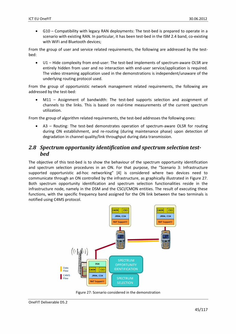
ICT EU OneFIT 30.06.2012
OneFIT Deliverable D5.2
45/117
G10 – Compatibility with legacy RAN deployments: The test-bed is prepared to operate in a scenario with existing RAN. In particular, it has been test-bed in the ISM 2.4 band, co-existing with WiFi and Bluetooth devices;
From the group of user and service related requirements, the following are addressed by the test-bed:
U1 – Hide complexity from end-user: The test-bed implements of spectrum-aware OLSR are entirely hidden from user and no interaction with end-user service/application is required. The video streaming application used in the demonstrations is independent/unaware of the underlying routing protocol used.
From the group of opportunistic network management related requirements, the following are addressed by the test-bed:
M11 – Assignment of bandwidth: The test-bed supports selection and assignment of channels to the links. This is based on real-time measurements of the current spectrum utilization.
From the group of algorithm related requirements, the test-bed addresses the following ones:
A3 – Routing: The test-bed demonstrates operation of spectrum-aware OLSR for routing during ON establishment, and re-routing (during maintenance phase) upon detection of degradation in channel quality/link throughput during data transmission.
2.8 Spectrum opportunity identification and spectrum selection test-bed
The objective of this test-bed is to show the behaviour of the spectrum opportunity identification and spectrum selection procedures in an ON. For that purpose, the “Scenario 3: Infrastructure supported opportunistic ad-hoc networking” [4] is considered where two devices need to communicate through an ON controlled by the infrastructure, as graphically illustrated in Figure 27. Both spectrum opportunity identification and spectrum selection functionalities reside in the infrastructure node, namely in the DSM and the CSCI/CMON entities. The result of executing these functions, with the specific frequency band assigned for the ON link between the two terminals is notified using C4MS protocol.
Data
Flow
C4MS
Flow
JRRM, CCM
RAT Support1
CSCICMON
JRRM, CCM
RAT Support1
CSCICMON
DSM
JRRM, CCM
RAT Support1
CSCICMON
SPECTRUM OPPORTUNITY
IDENTIFICATION
SPECTRUM SELECTION
Figure 27: Scenario considered in the demonstration

ICT EU OneFIT 30.06.2012
OneFIT Deliverable D5.2
46/117
The infrastructure node and the terminals are implemented by means of Universal Software Radio Peripheral (USRP) transceivers [24], as illustrated in Figure 28. USRP#1 will implement the infrastructure and the associated spectrum identification and selection functionalities, while USRP#2 and USRP#3 are the terminals exchanging data. Moreover, the ISM 2.4 GHz band will be used for the demonstration, detecting the available spectrum opportunities and allocating a portion of this band for the communication between terminals, based on real measurements made in this band.
Data
Flow
C4MS
Flow
USRP#1
USRP#2 USRP#3
SPECTRUM OPPORTUNITY
IDENTIFICATION
SPECTRUM SELECTION
Figure 28: Implementation of the demonstration scenario by means of USRP
Figure 29 presents the mapping of the spectrum opportunity identification and spectrum selection algorithms on the OneFIT architecture. In particular, both are located in the infrastructure, and the spectrum opportunity identification resides in the DSM module while the spectrum selection is carried out in the CMON entity. More specifically, Figure 30 presents the mapping of the spectrum selection in the CMON entity. The algorithm to decide the spectrum assignment will be located in the decision making entity while the knowledge database with statistics of the fittingness factor are included in the knowledge management entity.
JRRM
RAT 1 RAT 2 RAT n…
DSM
DSONPM
CCMCJ
MJ MC
JR CR
CS
Operator’s
Infrastructure
JRRM
RAT 1 RAT n…
CCMCJ
CR JR
Relay Node (Terminal or AP)
JJ-TN
Country-wide spectrum database
Geo-location database
SS
MS
OJ
CI/OM
-TN
JRRM
RAT 1 RAT n…
CCMCJ
CR JR
Terminal
CI/OM
-TT
OJOCOJOCJJ-TT
CSCI CMON CSCI CMON CSCI CMON
RR-TT RR-TN
Opportunistic network
JRRM
RAT 1 RAT 2 RAT n…
DSM
DSONPM
CCMCJ
MJ MC
JR CR
CS
Operator’s
Infrastructure
JRRM
RAT 1 RAT n…
CCMCJ
CR JR
Relay Node (Terminal or AP)
JJ-TN
Country-wide spectrum database
Geo-location database
SS
MS
OJ
CI/OM
-TN
JRRM
RAT 1 RAT n…
CCMCJ
CR JR
Terminal
CI/OM
-TT
OJOCOJOCJJ-TT
CSCI CMON CSCI CMON CSCI CMON
RR-TT RR-TN
JRRM
RAT 1 RAT 2 RAT n…
DSM
DSONPM
CCMCJ
MJ MC
JR CR
CS
Operator’s
Infrastructure
JRRM
RAT 1 RAT n…
CCMCJ
CR JR
Relay Node (Terminal or AP)
JJ-TN
Country-wide spectrum database
Geo-location database
SS
MS
OJ
CI/OM
-TN
JRRM
RAT 1 RAT n…
CCMCJ
CR JR
Terminal
CI/OM
-TT
OJOCOJOCJJ-TT
CSCI CMONCSCI CMON CSCI CMONCSCI CMON CSCI CMONCSCI CMON
RR-TT RR-TN
Opportunistic network
Spectrum Opportunity
IdentificationSpectrum Selection
Figure 29: Mapping of the algorithm in the OneFIT architecture

ICT EU OneFIT 30.06.2012
OneFIT Deliverable D5.2
47/117
JRRM
RAT 1 RAT 2 RAT n…
CCMCJ
JR CR
Operator’s infrastructure
CSCI
Context
Awareness
(status of
infra. netw.
and nodes)
Operator
Policy
Derivation
& Mgmt.
Profile
Management
(user class &
application
requirements
and constraints)
JJ-TNJRRM
DSM
CS
CSCI CMON
OM-TN
Decision Making
ON Suitability
Determination
CC
OJ
CI-TN
CC
RR-TNRAT
CMON
Know-
ledge
Manage-
ment
Decision Making
ON Creation,
Maintenance
&
Termination
Control
Execution of ON
establishment
Execution of ON
reconfiguration
Execution of ON
Termination
Context
Awareness
on status of
QoS and
application
flows
Operator
Policy
Acquisition
Profile
Management
(device
capabilities,
user
preferences)
Knowledge
Management
Result of ON Suitability
procedure, request for
creation of the ON
JRRM
RAT 1 RAT 2 RAT n…
CCMCJ
JR CR
Operator’s infrastructure
CSCI
Context
Awareness
(status of
infra. netw.
and nodes)
Operator
Policy
Derivation
& Mgmt.
Profile
Management
(user class &
application
requirements
and constraints)
JJ-TNJRRM
DSM
CS
CSCI CMON
OM-TN
Decision Making
ON Suitability
Determination
CC
OJ
CI-TN
CC
RR-TNRAT
CMON
Know-
ledge
Manage-
ment
Decision Making
ON Creation,
Maintenance
&
Termination
Decision Making
ON Creation,
Maintenance
&
Termination
Control
Execution of ON
establishment
Execution of ON
reconfiguration
Execution of ON
Termination
Control
Execution of ON
establishment
Execution of ON
reconfiguration
Execution of ON
Termination
Context
Awareness
on status of
QoS and
application
flows
Operator
Policy
Acquisition
Profile
Management
(device
capabilities,
user
preferences)
Knowledge
Management
Result of ON Suitability
procedure, request for
creation of the ON
Decision Making
entityKnowledge
Management entity
Figure 30: Mapping of the functional entities of the fittingness factor-based spectrum selection onto the CMON
Within the ON lifecycle, the spectrum selection problem considered here is applicable in the following two stages:
ON creation: In this case the algorithm is executed whenever a new link has to be established in an ON and for that purpose an adequate spectrum pool has to be assigned;
ON maintenance stage: In this case, the algorithm is executed whenever some changes in the radio environment have been detected such as modifications in the radio and interference conditions of a certain link, or a link release (meaning that we can reallocate the spectrum that was used by the released link to another link). As a result of the spectrum selection during ON maintenance, it is possible that spectrum handover procedures are triggered, whenever the spectrum allocated to any of the active links is modified.
Since the target of the demonstration is the spectrum opportunity identification and spectrum selection, the demonstration implements only the ON creation and ON maintenance stages. It is assumed that the decision to create an ON among the two devices has been previously made in the ON suitability phase. Similarly, a network-centric operation is assumed, in which the infrastructure makes the spectrum selection decisions. Details on the specific procedures for the two stages are given in sections 3.3.2.1 and 3.3.3.1.
The C4MS signalling is realized using the implementation option based on IEEE 802.21 “Media-Independent Handover (MIH) Services” described in chapter 5. Specific details on the considered messages in the test-bed are given in [7].
The spectrum opportunity identification and selection test-bed brings to the OneFIT validation platform the functionalities needed to analyse and decide in real time the current occupation of spectrum blocks in the ISM 2.4 GHz band and to perform the decision making about which of the available spectrum blocks can be more suitable to be allocated to a certain ON radio link with certain associated requirements. In this respect, this test-bed offers possible cooperation opportunities to some other parts of the OneFIT validation platform where the dynamic assignment of a spectrum to ON links is relevant. For example, additional spectrum usage information could be provided to the

ICT EU OneFIT 30.06.2012
OneFIT Deliverable D5.2
48/117
DSM in the “Opportunistic networking demonstrator”. The decision-making logic for the spectrum allocation could also be exploited. Also, Cognitive radio test-bed for spectrum-aware routing could exploit the results coming from the algorithms for spectrum opportunity identification and the decision making for spectrum selection. These potential ways of cooperation among test-beds will be further considered and elaborated in the framework of the activity on result analysis and validation which runs from July to December 2012.
2.8.1 Addressed system requirements
The following system requirements are addressed within this test-bed: G1-G3, G7, G10, M3, M5, M11, A1 and A2.
From the group of general requirements the following ones are addressed:
G1 – Communication with the infrastructure: The test-bed includes a USRP node that emulates the behaviour of the infrastructure in charge of controlling the ON formed by the two terminals. Both terminals communicate with the infrastructure to exchange the control C4MS messages allowing the ON creation and ON maintenance procedures.
G2 – Communication between terminals: The test-bed includes a link between the two USRPs used to transmit data in the allocated spectrum block. The efficiency in the communication is monitored by the terminals to identify degradations and request the ON modification.
G3 – Versatile spectrum use: The test-bed performs a dynamic spectrum assignment, after having identified based on measurements the available spectrum blocks depending on the current interference conditions in the scenario where it operates;
G7 – Creation of opportunistic networks: The test-bed allows the creation of an ON link and addresses the problems of spectrum opportunity identification and selection to allocate the appropriate spectrum to the created link. The procedure for ON creation implemented in the test-bed is detailed in section 3.3.2.1.
G10 – Compatibility with legacy RAN deployments: The test-bed is prepared to operate in a scenario with existing RAN. In particular, it has been test-bed in the ISM 2.4 band, co-existing with WiFi and Bluetooth devices.
From the group of opportunistic network management related requirements, the following ones are addressed by the test-bed:
M3 – Creation of opportunistic networks: The test-bed implements the ON creation stage, in particular the selection of spectrum for an ON link to be established. The procedure for ON creation implemented in the test-bed is detailed in section 3.3.2.1.
M5 – Maintenance of opportunistic networks: The test-bed monitors the efficiency in the data transmission between terminals using the allocated spectrum. Whenever the efficiency falls below a specific threshold the ON modification procedure is triggered to request for a different spectrum block. The procedure for ON maintenance implemented in the test-bed is detailed in section 3.3.3.1.
M11 – Assignment of bandwidth: The test-bed decides the adequate spectrum blocks to be assigned to the link between the two terminals forming the ON. This is based on real-time measurements of the current spectrum utilization.
From the group of algorithm related requirements, the test-bed addresses the following ones:

ICT EU OneFIT 30.06.2012
OneFIT Deliverable D5.2
49/117
A1 – Context awareness: This is addressed in two different ways by the test-bed. On the one hand, whenever the ON link has to be established, the USRP emulating the infrastructure performs the spectrum opportunity identification by measuring the spectrum band (ISM2.4) and identifying which spectrum blocks are available. On the other hand, once the link has been established, the efficiency in the data communication is monitored to identify if a degradation occurs (due to e.g. interference) and then to request for another spectrum block.
A2 – Decision making: The test-bed carries out the spectrum selection decision making algorithm to decide on the adequate spectrum block to be allocated to the ON link that has to be established, or after degradation has been detected in the assigned block during data transmission.
2.9 Open platform wireless mesh network test-bed
The open platform wireless mesh network (WMN) test-bed is developed in order to test and evaluate scenario 5 specific use cases (in unlicensed spectrum). Also, WP4 algorithms “Application cognitive multipath routing in wireless mesh networks” and “Content conditioning and distributed storage virtualization/aggregation for context driven media delivery” are validated on this platform.
The WMN test-bed includes (see Figure 31):
Wireless mesh network (WMN) test-bed with open platform access points (APs) based on MikroTik router-boards and OpenWRT system;
Database of contextual information;
Traffic generator for emulating traffic flows;
Simple network management protocol (SNMP) for network monitoring and contextual data gathering;
Optimized link state routing (OLSR) protocol for route discovery, establishment and maintenance;
End user’s terminals.
Open platform WMN nodes are based on MikroTik router boards RB800 and RB433AH and OpenWRT system. More details about these components can be found in D5.1 [2].
The OneFIT building blocks (CMON and CSCI logic) are implemented in the centralized network management server. The SNMP protocol is used as a variant of the C4MS (see section 5) protocol for contextual data gathering and exchange of control messages. OLSR protocol is used for route discovery and establishment.
The open platform WMN test-bed is included into the OneFIT validation platform as part of the infrastructure side for enabling aggregation of infrastructure’s backhaul resources (bandwidth and caching storage).
This test-bed can be used in cooperation with test-beds which are providing resource aggregation in the access side of the WMN in order to demonstrate the overall resource aggregation (in access and backhaul side of the infrastructure).
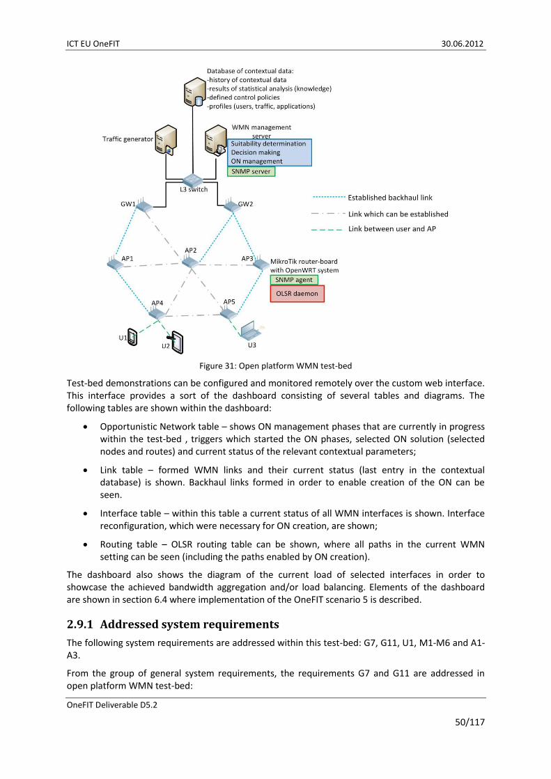
ICT EU OneFIT 30.06.2012
OneFIT Deliverable D5.2
50/117
Figure 31: Open platform WMN test-bed
Test-bed demonstrations can be configured and monitored remotely over the custom web interface. This interface provides a sort of the dashboard consisting of several tables and diagrams. The following tables are shown within the dashboard:
Opportunistic Network table – shows ON management phases that are currently in progress within the test-bed , triggers which started the ON phases, selected ON solution (selected nodes and routes) and current status of the relevant contextual parameters;
Link table – formed WMN links and their current status (last entry in the contextual database) is shown. Backhaul links formed in order to enable creation of the ON can be seen.
Interface table – within this table a current status of all WMN interfaces is shown. Interface reconfiguration, which were necessary for ON creation, are shown;
Routing table – OLSR routing table can be shown, where all paths in the current WMN setting can be seen (including the paths enabled by ON creation).
The dashboard also shows the diagram of the current load of selected interfaces in order to showcase the achieved bandwidth aggregation and/or load balancing. Elements of the dashboard are shown in section 6.4 where implementation of the OneFIT scenario 5 is described.
2.9.1 Addressed system requirements
The following system requirements are addressed within this test-bed: G7, G11, U1, M1-M6 and A1-A3.
From the group of general system requirements, the requirements G7 and G11 are addressed in open platform WMN test-bed:

ICT EU OneFIT 30.06.2012
OneFIT Deliverable D5.2
51/117
G7 - Creation of opportunistic networks: implemented algorithm for opportunistic, application aware multipath routing in backhaul of WMNs provides selection of appropriate set of multiple paths in the backhaul of the WMN over which the requested QoS requirements of end users can be achieved. ON is created among WMN nodes participating in selected multiple paths by creating opportunistic backhaul links between available dormant backhaul interfaces of WMN nodes. Established multiple paths in the WMN backhaul will be terminated (ON termination) when the management system detects that the underlying single path routing can provide required QoS to the end users.
G11 – Resource efficiency: opportunistic and application aware multipath routing algorithm is implemented in this test-bed in order to provide better load balancing in WMN backhaul and better backhaul bandwidth utilization while, at the same time, QoS requirements of the end users are met.
Regarding the group of system requirements related to users and services, U1 requirement is addressed in this test-bed implementation:
U1 – Hide complexity from the end user: complexity of the multipath routing in the backhaul of WMNs is hidden form the end users, since all reconfiguration and management are done between WMN stations. Application used by the end user is recognized (this feature is currently performed manually, but it will be automatized by the end of the project) and its load is routed over one of the multiple paths which are made available by ON creation.
From the group of ON management related requirements, M1-M6 requirements are addressed in this test-bed implementation:
M1 – Identification of the need for an opportunistic network: SNMP based WMN monitoring system collects all relevant contextual parameters every 1 minute. These contextual parameters are stored into the contextual database. Implemented multipath routing algorithm checks the values of selected contextual parameters (number of end users and their QoS requirements and available bandwidth on currently used backhaul paths and ETX values of these paths) as well as trend in which those values are changing. When defined triggering levels are met, the suitability determination phase of the algorithm starts.
M2 – Suitability determination: implemented multipath routing algorithm performs suitability determination upon trigger detection. A suitability of using multiple paths for solving the problem at hand is checked. For more details please check the section 3.3.1.5.
M3 – Creation of opportunistic networks: when multipath routing is selected as suitable for solving detected problem, new backhaul paths will be established by turning on dormant backhaul interfaces of selected WMN nodes and assigning appropriate 802.11a channel to them in order to form selected additional backhaul links. After multipath routing is established, application/users’ loads are distributed among multiple paths in the application aware manner. More details regarding ON creation can be found in section 3.3.2.7.
M4 – Connection set-up: new backhaul links are made when multiple path set is selected in suitability determination phase. All WMN stations in this test-bed have two interfaces for backhaul connectivity. Unutilized interfaces are turned on when multipath routing is established.
M5 – Maintenance of opportunistic networks: SNMP based monitoring system continues gathering relevant contextual parameters from WMN when ONs are established. QoS capabilities of all backhaul paths are constantly checked and, when needed, ONs are reconfigured (different set of multiple paths are selected) in a manner which can address changes in QoS requirements.

ICT EU OneFIT 30.06.2012
OneFIT Deliverable D5.2
52/117
M6 – Release of opportunistic networks: when there is no longer a need for multipath routing (single path routing can provide necessary QoS levels), established ONs will be terminated and selected backhaul paths from ON supported multiple paths sets will be terminated (certain backhaul links will be terminated – corresponding interfaces will be turned off). By returning to single path routing mode of operation, when multipath routing is no longer needed, WMN management system lowers possibilities for interference in WMN backhaul and, at the same time, achieves power savings by turning of unnecessary backhaul interfaces.
Regarding the algorithm related system requirements, the open platform WMN test-bed addresses the following:
A1 – Context awareness: SNMP based monitoring system collects necessary contextual parameters form WMN environment. Implemented multipath routing algorithm checks the context values and trends in their changes form contextual database in order to detect a need for ON creation and to perform a proper suitability determination.
A2 – Decision making: implemented multipath routing algorithm makes decisions when to start ON suitability determination based on values of monitored contextual parameters. During the suitability determination phase algorithm decides if the multipath routing is applicable for solving the problem at hand within current contextual boundaries. Creation phase will establish the first multiple paths set which fulfils the QoS requirements. Also, decisions are made regarding when to reconfigure created ONs and when to terminate them.
A3 – Routing: routing is performed with the OLSR protocol. Implemented multipath routing algorithm selects appropriate set of multiple paths, establishes necessary additional links and makes instructions regarding the routing schedule for access traffic (which load over which path in multiple path sets). These changes are detected by the underling OLSR, which continues with routing in accordance with reconfigured WMN backhaul.

ICT EU OneFIT 30.06.2012
OneFIT Deliverable D5.2
53/117
3 Implementation of the OneFIT cognitive management system
The OneFIT’s infrastructure governed opportunistic networks management is divided into two building blocks, namely the “Cognitive management System for the Coordination of the infrastructure” (CSCI) and the “Cognitive Management system for the Opportunistic Network” (CMON).
The CSCI is mainly responsible for the activities before an ON is created. This includes ON opportunity detection and ON suitability determination. When the CSCI has made a decision that an ON is suitable, the decision is then sent to the CMON.
The CMON is responsible for executing on the ON design, obtained from the CSCI, and then operationally supervising the created ON. This entity is in charge of the creation, maintenance and termination of the opportunistic network. Moreover, the CMON is responsible for the coordination of nodes in the ON. The CMON and the CSCI are located in both the operators’ infrastructure and the terminal side.
A detailed view of the CSCI and CMON functional building blocks is shown in Figure 34 and Figure 35. These building blocks are realized by implementation of the following algorithms (tasks) into the corresponding test-beds which comprise the OneFIT validation platform:
Task 1: Suitability determination for the coverage extension scenario (implemented in the Opportunistic networking demonstrator, which is described in section 2.2);
Task 2: Fittingness factor-based spectrum selection (implemented in the Spectrum opportunity identification and spectrum selection test-bed, which is described in section 2.8);
Task 3: Algorithm on knowledge-based suitability determination and selection of nodes and routes (implemented in the prototyping platform for the management of opportunistic networks, which is described in section 2.1);
Task 4: Route pattern selection in ad-hoc networks (implemented in the Opportunistic ad-hoc network demonstrator, which is described in section 2.4);
Task 5: Multi-flow routes co-determination (implemented in the Opportunistic ad-hoc network demonstrator, which is described in section 2.4);
Task 6: QoS and spectrum-aware routing techniques (implemented in the Cognitive radio test-bed, which is described in section 2.7);
Task 7: Application cognitive multi-path routing in wireless mesh networks (implemented in the Open platform wireless mesh network test-bed, which is described in section 2.9);
Task 8: UE-to-UE trusted direct path (implemented in the Direct D2D communication test-bed, which is described in section 2.6);
Task 9: Capacity extension through femtocells (implemented in the prototyping platform for the management of opportunistic networks, which is described in section 2.1).
The listed algorithms are described in more detail in D4.1 [8] and D4.2 [9]. Their implementation into the OneFIT validation platform is described in D4.2 [9]. Their mapping onto the ON related challenges, the ON management phases, CSCI and CMON entities and the OneFIT scenarios is shown in Figure 32.

ICT EU OneFIT 30.06.2012
OneFIT Deliverable D5.2
54/117
Suit
abili
ty d
eter
min
atio
n f
or
the
cove
rage
ext
ensi
on
sce
nar
io
Fitt
ingn
ess
fact
or-
bas
ed s
pec
tru
m s
elec
tio
n
Alg
ori
thm
on
kn
ow
led
ge-b
ased
su
itab
ility
det
erm
inat
ion
an
d s
elec
tio
n o
f n
od
es a
nd
ro
ute
s
Ro
ute
pat
tern
sel
ecti
on
in a
d-h
oc
net
wo
rks
Mu
lti-
flo
w r
ou
tes
co-d
eter
min
atio
n
Qo
S an
d s
pec
tru
m-a
war
e ro
uti
ng
tech
niq
ues
Ap
plic
atio
n c
ogn
itiv
e m
ult
i-p
ath
ro
uti
ng
in w
irel
ess
mes
h n
etw
ork
s
UE-
to-U
E tr
ust
ed d
irec
t p
ath
Cap
acit
y ex
ten
sio
n t
hro
ugh
fem
toce
llsNode discovery x x x
Node selection x x
Route selection x x x x x x x
Spectrum identification x x
Spectrum selection x x
Suitability x x x x x
Creation x x x x x x x
Maintenance & Termination x x x x x x x x
CMON terminal x x
CSCI terminal x x x x
CMON Infrastructure x x x x x x
CSCI Infrastructure x x x x x
Scenario 1 x x x x x x
Scenario 2 x x x x x x x x
Scenario 3 x x x x x x
Scenario 4 x x x x
Scenario 5 x x x
Figure 32: Mapping of the implemented algorithms onto the ON related challenges, the ON management phases, CMON and CSCI entities and the OneFIT scenarios

ICT EU OneFIT 30.06.2012
OneFIT Deliverable D5.2
55/117
Different triggers will require utilization of different algorithmic approaches. Decision making procedures of the OneFIT cognitive management system will select appropriate algorithmic approach (or combination of approaches) for solving the problems at hand, which are identified by detected triggers. Mapping of the algorithms, which are implemented into the OneFIT validation platform, onto the defined triggers is shown in Figure 33.
Figure 33: Mapping of the algorithmic solutions onto the triggering events and states
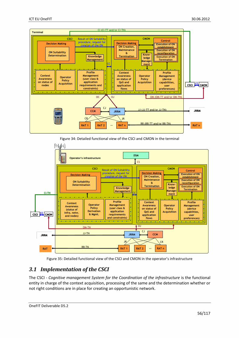
ICT EU OneFIT 30.06.2012
OneFIT Deliverable D5.2
56/117
JRRM
RAT 1 RAT 2 RAT n…
CCMCJ
CR JR
Terminal
CSCI
JJ (JJ-TT and/or JJ-TN) JRRM
CMON
CSCI CMON
OM (OM-TT and/or OM-TN)
Context
Awareness
on status of
nodes
Operator
Policy
Acquisition
Profile
Management
(user class &
application
requirements and
constraints)
CC
CI (CI-TT and/or CI-TN)
CC
OJOC
Decision Making
RR (RR-TT and/or RR-TN)RAT n
Context
Awareness
on status of
QoS and
application
flows
Operator
Policy
Acquisition
Profile
Management
(device
capabilities,
user
preferences)
Knowledge
Management
ON Suitability
Determination
Result of ON Suitability
procedure, request for
creation of the ON
Know-
ledge
Manage-
ment
Decision Making
ON Creation,
Maintenance
&
Termination
Control
Execution of ON
establishment
Execution of ON
reconfiguration
Execution of ON
Termination
JRRM
RAT 1 RAT 2 RAT n…
CCMCJ
CR JR
Terminal
CSCI
JJ (JJ-TT and/or JJ-TN) JRRM
CMON
CSCI CMON
OM (OM-TT and/or OM-TN)
Context
Awareness
on status of
nodes
Operator
Policy
Acquisition
Profile
Management
(user class &
application
requirements and
constraints)
CC
CI (CI-TT and/or CI-TN)
CC
OJOC
Decision Making
RR (RR-TT and/or RR-TN)RAT n
Context
Awareness
on status of
QoS and
application
flows
Operator
Policy
Acquisition
Profile
Management
(device
capabilities,
user
preferences)
Knowledge
Management
ON Suitability
Determination
Result of ON Suitability
procedure, request for
creation of the ON
Know-
ledge
Manage-
ment
Decision Making
ON Creation,
Maintenance
&
Termination
Decision Making
ON Creation,
Maintenance
&
Termination
Control
Execution of ON
establishment
Execution of ON
reconfiguration
Execution of ON
Termination
Control
Execution of ON
establishment
Execution of ON
reconfiguration
Execution of ON
Termination
Figure 34: Detailed functional view of the CSCI and CMON in the terminal
JRRM
RAT 1 RAT 2 RAT n…
CCMCJ
JR CR
Operator’s infrastructure
CSCI
Context
Awareness
(status of
infra. netw.
and nodes)
Operator
Policy
Derivation
& Mgmt.
Profile
Management
(user class &
application
requirements
and constraints)
JJ-TNJRRM
DSM
CS
CSCI CMON
OM-TN
Decision Making
ON Suitability
Determination
CC
OJ
CI-TN
CC
RR-TNRAT
CMON
Know-
ledge
Manage-
ment
Decision Making
ON Creation,
Maintenance
&
Termination
Control
Execution of ON
establishment
Execution of ON
reconfiguration
Execution of ON
Termination
Context
Awareness
on status of
QoS and
application
flows
Operator
Policy
Acquisition
Profile
Management
(device
capabilities,
user
preferences)
Knowledge
Management
Result of ON Suitability
procedure, request for
creation of the ON
JRRM
RAT 1 RAT 2 RAT n…
CCMCJ
JR CR
Operator’s infrastructure
CSCI
Context
Awareness
(status of
infra. netw.
and nodes)
Operator
Policy
Derivation
& Mgmt.
Profile
Management
(user class &
application
requirements
and constraints)
JJ-TNJRRM
DSM
CS
CSCI CMON
OM-TN
Decision Making
ON Suitability
Determination
CC
OJ
CI-TN
CC
RR-TNRAT
CMON
Know-
ledge
Manage-
ment
Decision Making
ON Creation,
Maintenance
&
Termination
Decision Making
ON Creation,
Maintenance
&
Termination
Control
Execution of ON
establishment
Execution of ON
reconfiguration
Execution of ON
Termination
Control
Execution of ON
establishment
Execution of ON
reconfiguration
Execution of ON
Termination
Context
Awareness
on status of
QoS and
application
flows
Operator
Policy
Acquisition
Profile
Management
(device
capabilities,
user
preferences)
Knowledge
Management
Result of ON Suitability
procedure, request for
creation of the ON
Figure 35: Detailed functional view of the CSCI and CMON in the operator’s infrastructure
3.1 Implementation of the CSCI
The CSCI - Cognitive management System for the Coordination of the infrastructure is the functional entity in charge of the context acquisition, processing of the same and the determination whether or not right conditions are in place for creating an opportunistic network.

ICT EU OneFIT 30.06.2012
OneFIT Deliverable D5.2
57/117
The CSCI is responsible for the detection of situations where an ON may be useful as part of the ON suitability determination phase. The CSCI delegates the actual creation, maintenance and termination of a given ON to the associated CMON functional entity and it is located in both the operators’ infrastructure side (then called “CSCI-N”) and the terminal side (then called “CSCI-T”).
The main tasks of the CSCI are:
ON opportunity detection and ON trigger recognition;
ON suitability determination;
ON blueprint derivation;
Operator’s policy derivation and acquisition;
Enabling necessary level of context awareness;
Profiling of users and applications and derivation of their connections;
Instructing the CMON to create and/or extend the ON;
Communicating with CSCI entities of other nodes in the network.
The ON opportunity detection requires a set of triggers and scenarios to be defined. These triggers and scenarios are derived from performance evaluation of created ONs and other solutions used for overcoming detected problems. Triggers are set of different threshold levels of certain relevant contextual parameters (link congestion, out of coverage, QoS requirements, resource utilization, and users’ requests). Implemented algorithms provide certain trigger detections:
Insufficient access bandwidth and poor load balancing among BSs are detected by procedures developed within Tasks 3 and 9;
Link congestion and poor load balancing in backhaul side of the infrastructure are detected by the procedures developed within Task 7 (in the backhaul of the WMNs);
QoS requirements for applications used by users are detected (through policy acquisition) by procedures of Task 4, task 6 and Task 7;
Spectrum availability is detected by procedures presented in Task 2 and Task 6;
When these thresholds are reached, the ON suitability determination process can start. The Suitability Determination is a centralized process, with the decision making located typically in the infrastructure but in some cases (e.g. out-of-coverage scenario) located inside a device. The decision making is based on infrastructure-level information provided by functional entities in the network and user/device-level information provided by the CSCI-T entities from a selected set of devices. The Suitability Determination runs before the creation of an ON but also during the lifetime of the ON in order to check that context changes and ON reconfigurations (information from CMON) have not cancelled the benefit/suitability of the ON. The suitability determination requires context awareness in order to come up with a proper suitability conclusion. The implemented algorithms provide the suitability determination:
Task 1 provides suitability determination with respect to the size of the problematic area, mobility of the involved nodes and number of potentially involved nodes;
Task 3 and Task 9 provide suitability analysis based on previously gathered knowledge about ONs, nodes and routes;
Task 4 provides suitability determination with respect to creation of an ON on top of the ad-hoc network formed between end user terminals;

ICT EU OneFIT 30.06.2012
OneFIT Deliverable D5.2
58/117
Task 7 provides analysis of suitability of multi path routing in the backhaul side of the WMN for solving the problems of poor load balancing and insufficient access bandwidth. Also, knowledge about performance evaluation of the selected multiple paths sets is used in the suitability determination process.
When ON is detected as a suitable solution for a problem at hand, the ON blueprint needs to be derived. This blueprint consists of set of detected (identified) nodes (terminals and infrastructure), routes and spectrum. These entities are identified as suitable for creation of ON for solving detected problem. A good practice is to provide a certain level of redundancy in the set of identified candidate nodes, routes and spectrum chunks in order to allow creation process of CMON a certain level of freedom in selecting the appropriate set of mentioned entities. The ON blueprint is also accompanied with a set of necessary operator’s policies. The algorithms implemented into the OneFIT validation platform provide the ON blueprint:
Task 2 provides spectrum analysis and selection;
Task 3 and Task 9 provide node identification and candidate list derivation among terminals and infrastructure nodes;
Tasks 3, 4, 5, 6 and 8 provide candidate list of routes among terminals and between terminals and infrastructure nodes;
Task 7 provides candidate list of routes in the wireless backhaul side of the infrastructure.
All of the implemented algorithms take into account operator’s policies for providing proper suitability determination. Spectrum policies, QoS requirements, security requirements and ON related policies (nodes and routes) are defined and provided by operator. These policies can evolve if the gathered knowledge requires it.
Context awareness necessary for proper suitability determination is provided by all of the implemented algorithms:
Context awareness regarding spectrum is provided by Tasks 2 and 6;
Awareness regarding link congestions and traffic patterns between terminals is provided by Tasks 3, 4 and 6;
Context awareness regarding bandwidth utilization and traffic patterns in the backhaul side of the infrastructure network is provided by the Task 7;
Context awareness regarding capacity of the access side of the infrastructure is provided by the procedures in Task 3 and 9;
Awareness regarding used RATs is provided by Tasks 1, 3, 6 and 8;
Awareness regarding distribution of terminals is provided by procedures of the Tasks 1, 3, 4, 8 and 9;
Awareness regarding distribution and topology of the infrastructure nodes is provided by the Tasks 7 and 9;
Awareness regarding status of the infrastructure nodes is provided by the Tasks 7, 3 and 9.
Profiles of users and applications are derived by the operator. Users’ profiles can be updated by monitoring of the users activities (i.e. willingness to participate in ONs).
Set of candidate nodes, routes and spectrum portions (the ON blueprint) for creating the ON are sent to the corresponding CMON management entities over the C4MS protocol (for details regarding implementation of this protocol please check section 5 of this document).

ICT EU OneFIT 30.06.2012
OneFIT Deliverable D5.2
59/117
Communication between CSCI entities belonging to different nodes enables exchange of knowledge and gathered contextual information. Also, CSCI-N sends relevant operators policies and derived profiles to CSCI-T entities. In centralized cognitive management approach (i.e. Tasks 1, 3, 7 and 9) the main CSCI entity is located inside the centralized management server, while CSCI in nodes (infrastructure and terminal) are simple agents responsible for providing interface between centralized management system and reconfiguration engines within nodes.
3.2 Implementation of the CMON
The CMON - Cognitive Management system for the Opportunistic Network is responsible for executing on the design obtained from the CSCI and then operationally supervising the created ON. This entity is in charge of the creation, maintenance and termination (according to the policies maintained in the CSCI) of the opportunistic network. Moreover, the CMON is responsible for the coordination of nodes in the ON. The CMON is also located in both the operators’ infrastructure (CMON-N) and the terminal side (CMON-T).
Generally, the CMON in the operators’ infrastructure involves context awareness, policy acquisition and profile management which provide the input for the decision making mechanism. In the terminal side, the CMON provides functionality for the context awareness, the policy acquisition as defined by the operator and the profile management. The cognition relies on the fact that the knowledge management functional entity interacts with the previously mentioned entities in order to make better decisions in the future, according to the learned results.
The main tasks of the CMON are:
Context awareness through monitoring of the established ON and its environment;
Policy acquisition regarding QoS levels and ON related policies (i.e. when to terminate/reconfigure ON);
Knowledge derivation and management;
Decision making regarding the most appropriate selection of nodes, routes and spectrum portions from candidate sets provided by the CSCI;
Execution of ON creation – direct communication with CCM module;
ON monitoring and maintenance/reconfiguration;
ON termination.
The CMON will use the system’s monitoring capabilities in order to track performance of the established ONs and their environments (i.e. interference levels around ON, battery levels of included mobile terminals, load balancing, stabilization of situations which triggered the creation of the ON). All of the proposed tasks have procedures for monitoring of ONs and their environments or an interface towards operator’s monitoring systems and contextual databases.
Derived and defined policies are acquired from corresponding CSCI entity. These policies are used in decision making process when final set of nodes, routes and spectrum is selected from sets of possible candidates. Profiles of applications (defining QoS requirements) are used in Tasks 4, 6 and 7 for route selection process.
By monitoring of the ON and its environment, CMON gathers necessary contextual data regarding performance of the established ON and impact that it has on its environment. These contextual data are used for knowledge derivation which can be used in suitability determination and decision making processes. The implemented algorithms provide knowledge derivation:

ICT EU OneFIT 30.06.2012
OneFIT Deliverable D5.2
60/117
Penalization process, based on reinforced learning, for multiple paths sets is implemented in the Task 7;
Machine learning techniques are used for derivation of fittingness factor used for selection of spectrum (Task 2) and nodes/routes (Task 3).
Decision making is part of the creation, reconfiguration and termination phase. All of these ON management phases require proper decision before execution. The decision process needs to detect triggers for reconfiguration/termination and to derive set of nodes, routes and spectrum used for creation or reconfiguration of an ON. Figure 32 shows which of the ON management phases are addressed by which of the implemented algorithms (more detailed analysis of implementation of the ON management phases is given in subsection 3.3).
3.3 Implementation of ON management phases
This section presents how the different ON management phases have been implemented in the different components of the OneFIT validation platform presented in section 2, in accordance to the mapping between algorithm and ON management phases that was reflected in Figure 32. For that purpose, this section is subdivided into three parts, devoted to the ON suitability determination, ON creation and ON maintenance & termination stages. In each one the implemented algorithms covering each phase are presented. It is worth mentioning that in some cases, the three stages are integrated within the same algorithm. In these cases, the algorithm is presented in one of the sections and references are given in the other ones.
3.3.1 ON suitability determination
Different algorithms for ON suitability determination are implemented in the components of the OneFIT validation platform. In particular, this section details first the implementation of the suitability determination for the coverage extension scenario using the Opportunistic Network demonstrator. Then, the capacity extension and node selection algorithms implemented during the ON suitability determination phase in the prototyping platform for the management of opportunistic networks are presented. After this, the route selection algorithm implemented in the opportunistic ad-hoc network platform is described. It is presented in this section although it is general for the different ON stages. Finally the section describes the ON suitability determination for the application cognitive multi-path routing implemented in the wireless mesh network test-bed.
3.3.1.1 Suitability determination for the coverage extension scenario
For the suitability determination, the infrastructure must have knowledge about the nodes in the network, the capabilities of these nodes, the quality of the radio links and about neighbourhood relationships. Such information is typically already collected via Radio Resource Management (RRM) procedures or Joint Radio Resource Management (JRRM) procedures.
Measurements of the radio link can be reported from the terminal to the network using e.g. IEEE 802.21 MIH_Link_Parameters_Report.indiation, MIH_Link_Up.indication, MIH_Link_Going_Down .indication or MIH_Link_Detected.indication messages. Such messages are included for example in the message sequence chart in Figure 62 on page 92.
The suitability determination procedure is shown in Figure 36. When the RRM/JRRM receives an indication that a device is going out of the coverage of the current serving cell, the RRM/JRRM first searches for another cell to which a handover can be done. Only in the case that a handover to another cell is not possible, the CSCI/CMON is triggered to execute the suitability determination for the creation of an ON as shown in Figure 36. The CSCI/CMON then searches for another terminal in
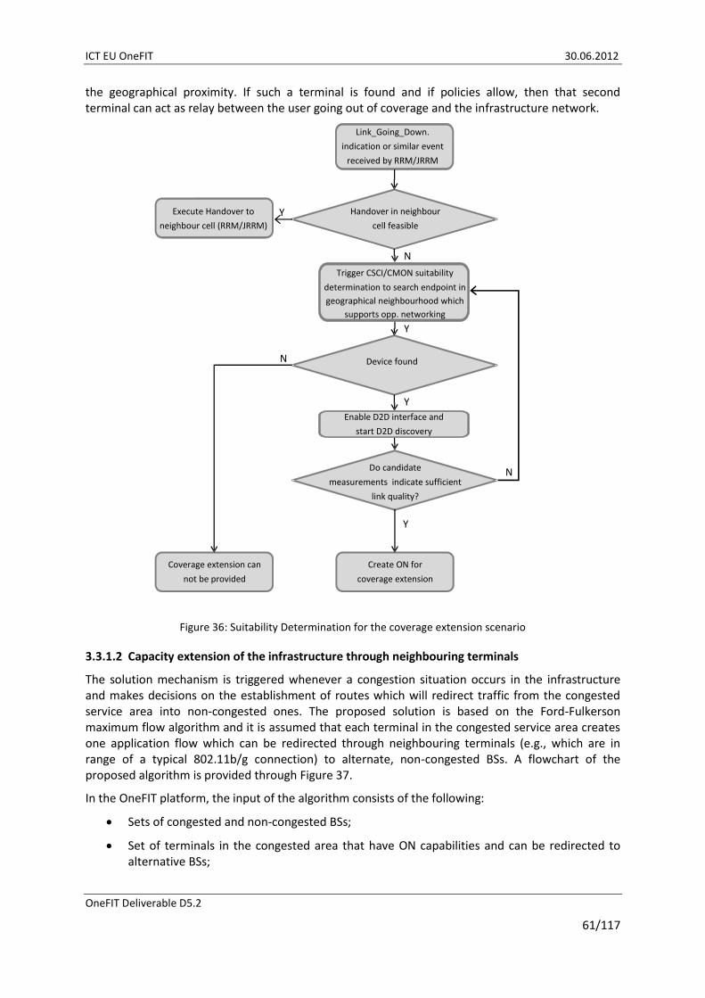
ICT EU OneFIT 30.06.2012
OneFIT Deliverable D5.2
61/117
the geographical proximity. If such a terminal is found and if policies allow, then that second terminal can act as relay between the user going out of coverage and the infrastructure network.
Coverage extension can
not be provided
Create ON for
coverage extension
Y
N
N
Y
Y
Y
Do candidate
measurements indicate sufficient
link quality?
Device found
Handover in neighbour
cell feasible
Execute Handover to
neighbour cell (RRM/JRRM)
Trigger CSCI/CMON suitability
determination to search endpoint in
geographical neighbourhood which
supports opp. networking
Enable D2D interface and
start D2D discovery
N
Link_Going_Down.
indication or similar event
received by RRM/JRRM
Figure 36: Suitability Determination for the coverage extension scenario
3.3.1.2 Capacity extension of the infrastructure through neighbouring terminals
The solution mechanism is triggered whenever a congestion situation occurs in the infrastructure and makes decisions on the establishment of routes which will redirect traffic from the congested service area into non-congested ones. The proposed solution is based on the Ford-Fulkerson maximum flow algorithm and it is assumed that each terminal in the congested service area creates one application flow which can be redirected through neighbouring terminals (e.g., which are in range of a typical 802.11b/g connection) to alternate, non-congested BSs. A flowchart of the proposed algorithm is provided through Figure 37.
In the OneFIT platform, the input of the algorithm consists of the following:
Sets of congested and non-congested BSs;
Set of terminals in the congested area that have ON capabilities and can be redirected to alternative BSs;

ICT EU OneFIT 30.06.2012
OneFIT Deliverable D5.2
62/117
Paths from source to destination. Each path originates from a ‘virtual’ source where terminals with ON capabilities in the congested area are connected and ends to a ‘virtual’ destination where BSs are connected.
To this respect, the following procedure is followed:
As soon as the BS detects the problematic situation, the CSCI sends a notification to the DSONPM which triggers the suitability determination mechanism;
The DSONPM constructs the set of the congested BSs and sends a request to the CSCI entities of the neighbouring BSs in order to determine the ones that can acquire a proportion of the traffic of the congested BS and construct the set of the non-congested BSs. The information is then sent to the congested BS that will execute the solution algorithm.
The selected BS sends a message (an Information.Request according to C4MS) to the other congested BSs in order to acquire the list of terminals with ON capabilities that can be redirected to alternative BSs. The information then is forwarded to the CMON.
The procedure then advances to the ON creation phase which is described at the respective section 3.3.2.2.
CSCI
CSCI
DSO
NPM
CSCI
CMO
NCM
ON
Figure 37: Algorithm on capacity extension of the infrastructure through neighbouring terminals
3.3.1.3 Selection of nodes through a fitness value evaluation
According to the OneFIT concept, ONs are created in an infrastructure-less manner under the supervision of the operator and include numerous network-enabled elements. To ensure application provisioning in an acceptable QoS level, the selection of the proper nodes, among all discovered nodes in the vicinity is rather essential. As a result, this approach proposes a mechanism for selecting nodes that will participate to the ON. The selection mechanism is based on a fitness function which is a weighted, linear formula which takes into consideration the following:

ICT EU OneFIT 30.06.2012
OneFIT Deliverable D5.2
63/117
Candidate node’s energy level;
Candidate’s node availability level which shall take into account:
- Capabilities (e.g. available interfaces/supported RATs, support of ON);
- Status of each node in terms of communication resources (e.g. status of the active links), storage (e.g. available buffer/cache), computing resources;
- Node’s location;
- The ability of a node to support a requested application;
Candidate node’s delivery probability (i.e., ratio of successfully transmitted packets to messages received by a node).
For example, if a neighbouring node does not have available buffer/cache because it is loaded with data packets waiting to be delivered, then the node is considered as unavailable, despite the fact that in terms of other parameters (e.g. energy) that node may perform in an acceptable level.
In the OneFIT platform, the input of the algorithm consists of the set of candidate nodes which are located in a specific service area that have ON capabilities (i.e., they have the ability to participate in an ON) and they are legitimate to participate in an ON according to the operator policies, in order to stress on the operator-governance during the ON formation. The output of the algorithm consists of the selected nodes that will form the ON. Then, the ON creation procedure is triggered in order to allow the nodes/terminals to negotiate between each other and establish links. A flowchart of proposed algorithm is provided through Figure 38.
Retrieve candidate node’s ifitness value (based on
energy, availability, delivery probability data)
Reject node i
Evaluate fitness value of node i
Is fitness value of node i greater
than threshold?
Accept node i and add it to the set of accepted nodes
Is the candidate node legitimate according to the policies of the
operator?
true
false
true
false
Figure 38: Algorithm on selection of nodes through a fitness value evaluation
The algorithm is implemented in the OneFIT prototyping platform described in section 2.1. The target of the demonstration is to depict the selection of nodes according to their fitness values as dictated by the algorithm in order to form an ON. The technical challenge of the algorithm is relevant to the Scenarios 1 and 2 related to “Opportunistic coverage extension” and “Opportunistic capacity extension” respectively which was identified in [3].

ICT EU OneFIT 30.06.2012
OneFIT Deliverable D5.2
64/117
Figure 39 provides an illustration of the implementation of the selection of nodes through a fitness value evaluation concept in the OneFIT platform.
Infrastructure failure
Nodes create an ON byconnecting to each other inorder to gain access to theinfrastructure
Infrastructurefailure resolved
ON is not neededanymore, thus it isterminated
Figure 39: Implementation of the selection of nodes through a fitness value evaluation concept in the OneFIT platform
3.3.1.4 Route pattern selection in ad-hoc networks
The route pattern selection algorithm is executed on the terminals, which are working in an ad-hoc environment, in the test-bed presented in section 2.4.
The algorithm is not particularly dedicated to one phase of the opportunistic network’s lifecycle; it applies as an intermediate layer for enabling of C4MS services. The algorithm fulfils the C4MS discovery service and the message forwarding and routing in the multi ad-hoc environment. For every packet (user data or signalling message), which is to be transmitted over the air through the opportunistic network, the algorithm is triggered to determine and establish the most appropriate route to reach the infrastructure.
The purpose of the algorithm is to establish and select the most appropriate route, in order to fulfil the QoS (or QoE) requested by the user applications. The algorithm also takes into account the handling of the signalling information exchanges by the application protocols.
For every message (user data or signalling messages), which is to be transmitted through the opportunistic network, the algorithm determines and selects the best route for transmitting the data to the destination.
The algorithm takes as an input the information provided by the lower layers and information provided by other nodes of the opportunistic network through the C4MS protocol. The information and metrics necessary to process the algorithm are contained in the knowledge database described in D3.3 [7].

ICT EU OneFIT 30.06.2012
OneFIT Deliverable D5.2
65/117
The C4MS discovery service is fulfilled by an active mechanism by exchanging routing messages between nodes involved in the opportunistic network. The C4MS forwarding/routing feature is fulfilled by the algorithm, which selects the routing pattern according to the QoS requested by user’s application and depending on the constraint related to the data transmission to be performed.
3.3.1.5 Application cognitive multi-path routing in wireless mesh networks
This algorithm falls into group of route selection and management algorithms. Its main function is selection and establishment of appropriate set of multiple paths in the wireless backhaul side of the wireless mesh networks (WMNs) in order to opportunistically achieve aggregation of the backhaul bandwidth. In this way, higher levels of backhaul bandwidth utilization and load balancing can be achieved. Algorithm addresses OneFIT scenario 5. More precisely a use case “Opportunistic backhaul bandwidth aggregation in unlicensed spectrum” is addressed. More detailed description of the algorithmic solution can be found in D4.2 [9].
The algorithm makes decision whether or not to create opportunistic network for providing multi-path routing as a solution for the detected problem. Besides having responsibility to decide when to kick in with the multipath routing, the algorithm also selects the multiple paths set which is able to provide required level of bandwidth aggregation and satisfy necessary QoS requirements of the used application. The net effect of opportunistic backhaul bandwidth aggregation is to match the access bandwidth of modern wireless technology with the adequate transport bandwidth in the backhaul/core network. The proposed solution makes use of OLSR as underlying routing protocol in the WMN. Necessary contextual data is gathered from WMN nodes with simple network monitoring protocol (SNMP). Decision making algorithm resides on the centralized management server, which monitors network status/state with SNMP protocol and stores gathered contextual data into database. The suitability determination phase of the algorithm is shown in Figure 40.
Figure 40: Suitability determination phase of the multipath routing algorithm
Three access traffic types are identified for the suitability determination phase:

ICT EU OneFIT 30.06.2012
OneFIT Deliverable D5.2
66/117
Type 1 represents the case where all of the access traffic belongs to one user who is using
one application which is sensitive to packet reordering and jitter (i.e. VoIP, live video
streaming);
Type 2 represents the use case where all of the access traffic belongs to one user who is
using one application which is not sensitive to problems which may arise from transferring
packets over multiple paths (i.e. download);
Type 3 is the case where access traffic is generated by one user who is using several
independent applications;
Type 4 is the case in which access traffic is generated by a number of users.
When trigger is detected, or predicted, the ON suitability determination phase starts. This phase is composed of three tasks performed in sequence. The task #1 is traffic examination with aim to determine which of the four types of access traffic, mentioned above, is responsible for the backhaul congestion at APi. Should the access traffic examination classify the problem in hands to be of type 1, then multi-path routing is considered as inappropriate solution and ON suitability determination results in the negative outcome. For all other types the control algorithm proceeds to the task #2, which is topology check (see Figure 40). The goal is to determine whether or not the given WMN topology allows for multiple paths to be formed in order to relieve the congestion at the node APi. It is important to note that should the APi happen to be a leaf node with only one neighbour it cannot be provided with more bandwidth if the link connecting it to its only neighbour is a bottleneck link on the current path. Finally, task #3 of the suitability determination (see Figure 40) is performing a check on whether or not an appropriate path can be found, which will, in addition to the current path, provide aggregation of the available backhaul bandwidth on the access side of APi.
Task #3 has two main parts. In the first one, paths, which are link disjoint (with regard to the detected bottleneck link) with the current path, are determined. Next, candidate paths are examined with respect to QoS constraints and aggregated backhaul bandwidth, which they can achieve in cooperation with the current path for APi. Paths, which are selected as solutions for the previous bandwidth aggregation problems for APi, are evaluated by the measured performance of the selected solution. Those paths which don’t result in satisfying performance (they are unstable, interference is increased, necessary aggregation is not achieved) are penalized. On the other hand the penalty for a selected path is decreased (until 0 is reached) when a provided solution results as expected. When a certain threshold in a penalty is reached, the path will not be taken into account as a solution for a problem. High penalty value (equal to threshold) has a cool-down period (certain number of executions of the algorithm) after which it is decreased in order to give the problematic path a new chance to prove its value. Described process of penalization is in line with the reinforced learning paradigm. The first path satisfying all of the constraints and requirements is selected as a solution in order to provide faster decision making. To achieve fairness in path selection, a set of all available paths for APi is randomly shuffled before algorithm is executed. In this way, all appropriate paths will be tested as a solution and, in time, a penalization process will sort them out.
The suitability determination tasks execution sequence depicted in Figure 40 facilitates the fastest possible decision making. This is achieved by starting the suitability determination with task #1 which is the least demanding in terms of execution time. Determinations associated with task #2 are somewhat more demanding. Nevertheless the most demanding determination is left for the task #3 which is performed only if the previous two tasks return positive outcome and warrant further engagement of computational resources.
The ON suitability determination can return three possible outcomes: (1) the multi-path is not suitable for the identified problem, ON will not be created among WMN nodes which continue with single path routing, (2) the combination of the current path with any other candidate path cannot

ICT EU OneFIT 30.06.2012
OneFIT Deliverable D5.2
67/117
provide solution (try suitability determination with different combinations of paths, which don’t include the current one – subject of future research), (3) additional path to the current one is successfully selected. This additional path will trigger the ON creation.
3.3.2 ON creation
This section addresses the implementation of the ON creation stage in the different components of the OneFIT demonstration platform. First, the section starts with the implementation in the case of the spectrum opportunity identification and selection test-bed. Then, the implementations in the prototyping platform for the management of opportunistic networks are presented, for the cases of the capacity extension scenario. After this, the multi-flow routes co-determination algorithm used by the opportunistic ad-hoc network demonstrator is presented, followed by the QoS and spectrum-aware routing techniques. The section concludes with the ON creation stage of the application cognitive multi-path routing for the wireless mesh networks test-bed, and the UE-to-UE trusted direct path.
3.3.2.1 Spectrum Opportunity Identification and Selection
The focus of the test-bed presented in section 2.8 is on the procedures related with spectrum opportunity identification and selection, while it is assumed that the decision to create an ON among two devices has been previously made in the ON suitability phase. Then, the focus is on the ON creation and ON maintenance stages. Similarly, a network-centric operation is assumed, in which the infrastructure makes the spectrum selection decisions.
The implemented procedure for the ON creation is shown in Figure 41. The steps of the procedure are explained below. It is assumed that, as a result of the ON suitability determination phase, UE#1 has determined that the direct link establishment can be assisted by the infrastructure.
1. A MIH_C4MS_ONN.request message is sent from UE#1 to the infrastructure to start the ON-Negotiation procedure intended to obtain a valid configuration of the radio link. The message indicates the terminals involved and the QoS requirements that the link is expected to support, in terms of required bit rate. It is assumed that the information in terms of supported bands by the terminals is already known by the network (e.g. obtained during the suitability stage).
2. The infrastructure sends a MIH_C4MS_ONN.request to UE#2 in order to inform the terminal about the intention to establish a direct radio link with UE#1 and allow it to join the negotiation process for the derivation of the radio link configuration;
3. UE#2 replies with a MIH_C4MS_ONN.response message to BS by means of which it notifies its acceptance for the establishment of the link;
4. At this point, CSCI/CMON entities in the BS send an inquiry to the Dynamic Spectrum Management (DSM) entity to determine spectrum availability for the link. As a result of this inquiry, the spectrum opportunity identification algorithm is executed to determine the available spectrum blocks.
5. DSM reply provides the CSCI/CMON entities in the BS with the available spectrum blocks. This is used by the Spectrum Selection algorithm to decide on the spectrum to be allocated to the link.
6. The proposed ON configuration with the selected spectrum is transferred to UE#1 by issuing a MIH_C4MS_ONN.response message. This message also includes the ON identifier to be used in future communications.

ICT EU OneFIT 30.06.2012
OneFIT Deliverable D5.2
68/117
7. To create the ON, the UE#1 sends a MIH_C4MS_ONC.request to the BS with the final ON configuration;
8. BS sends another MIH_C4MS_ONC.request towards UE#2 with the final ON configuration;
9. UE#2 replies with a MIH_C4MS_ONC.response message where a successful result-code is reported to indicate that the terminal is ready to establish the link;
10. BS concludes the ON creation procedure by sending a MIH_C4MS_ONC.response message to UE#1;
11. The link establishment takes place at this point;
12. Finally, the creation of the ON is notified to the infrastructure from UE#1 by sending a MIH_C4MS_ONSN.indication message.
Figure 41: Implemented message exchange for the ON creation.
From an algorithmic perspective, the problem considered in the test-bed is the selection of the spectrum to be assigned to a set of radio links between a pair of terminals and/or infrastructure nodes. The purpose of each radio link is to support a certain CR application with certain bit rate requirements. The algorithm uses as input the set of available spectrum pools resulting from the spectrum opportunity identification, together with the characteristics of each pool in terms of available bit rate based on radio considerations.

ICT EU OneFIT 30.06.2012
OneFIT Deliverable D5.2
69/117
The algorithm makes use of the fittingness factor concept as a metric to capture how suitable a specific spectrum pool is for a specific radio link [9]. Different statistics regarding the observed fittingness factor based on the accumulated experience are stored and used to make decisions. The spectrum selection is done either when a new application needs to be established or as a result of changes in the radio conditions or in the current active links.
The following two algorithms are implemented in the test-bed, and executed at the infrastructure as reflected in the message sequence chart of the ON creation in Figure 41.
3.3.2.1.1 Spectrum Opportunity Identification algorithm
The spectrum opportunity identification is at the DSM entity of the infrastructure. The algorithm executes two different procedures: the measurement procedure and the spectrum block formation.
In the measurement procedure, the total band (i.e. in the platform the ISM 2.4 band) is subdivided in N smaller portions of equal band ∆f. The measurement algorithm consists in performing an energy detection sensing (during a period of time ∆t) for each ∆f portion until measuring the total band, starting from frequency F_min_band. This measurement is repeated Num_Meas times. Then, based on the multiple measurements carried out, the opportunity index is obtained for each portion, defined as the fraction of measurements in which this portion has been detected as available.
In the spectrum block formation procedure, the consecutive spectrum blocks with opportunity index above a certain threshold are grouped in blocks. Each block is formed by a maximum of Pmax portions (i.e. in case there are more than Pmax consecutive portions, they are splitted in different blocks).
For each block, the algorithm returns the 2-tuple ( , )k k kSB f BW composed of the following
parameters:
- fk central frequency of the block;
- BWk is the bandwidth of the block.
The reader is referred to [9] for the detailed pseudo-code of this algorithm.
3.3.2.1.2 Spectrum Selection algorithm
During the ON creation stage, the spectrum selection algorithm is executed at the infrastructure node whenever a new link has to be established
The algorithm is based on estimating the fittingness factor for each link and available spectrum block based on a knowledge database that is maintained with different fittingness factor statistics. Details on the algorithm, including its functional architecture and the statistics stored in the knowledge database are given in [15] and [9].
The algorithm takes as inputs the list of available spectrum blocks provided by the DSM after execution of the spectrum opportunity identification algorithm, the bit rate requirements of the link to be assigned, the list of current assignments, and a database with different statistics capturing the historical evolution of the fittingness factor that is obtained based on measurements of link context information when the different links utilise the available blocks.
The algorithm output is the list of spectrum assignments to each of the existing links.
The reader is referred to [9] for the detailed pseudo-code of this algorithm included in the demonstration platform.

ICT EU OneFIT 30.06.2012
OneFIT Deliverable D5.2
70/117
3.3.2.2 Capacity extension of the infrastructure through neighbouring terminals
In this phase, the CMON of the selected BS, i.e. the congested BS that will execute the Ford-Fulkerson algorithm, needs to collect the possible paths from the terminals of the congested BSs to non-congested areas. Therefore, the following procedure takes place:
The CMON of the selected BS sends a message (an ON_Negotiation.Request according to C4MS) to the CMONs of the other congested BSs in order to request the aforementioned paths;
The CMONs of the congested BSs forward the message to the CMONs of the terminals with ON capabilities and a discovery process starts. As soon as the paths are discovered, an answer is sent back to the CMONs of the congested BSs and to the CMON of the selected BS.
The CMON of the selected BS has acquired the necessary information and the Ford-Fulkerson algorithm is executed.
The output of the algorithm consists of the selected paths for each terminal with ON capabilities for which the flow is maximized, as described in [9]. A path includes a starting point (e.g. a terminal in the congested region), an ending point (e.g. a BS), and the links that create the full path from the starting to the ending point (each link is identified by a starting point and ending point each of which is an intermediate node).
The algorithm is implemented in the OneFIT prototyping platform described in section 2.1. The target of the demonstration is to depict the formation of paths as dictated by the algorithm in order to redirect traffic from congested to non-congested BSs. The technical challenge of the algorithm is relevant to the Scenario 2: “Opportunistic capacity extension” which was identified in [3].
The algorithm is executed to the CMON agent of the BS and ONs are created that redirect a number of macro-terminals to alternative BSs, as can be seen at the figure below.
Figure 42: Resolution of hotspot situation by redirecting traffic to alternate BSs

ICT EU OneFIT 30.06.2012
OneFIT Deliverable D5.2
71/117
3.3.2.3 Selection of nodes through a fitness value evaluation
The algorithm presented in section 3.3.1.3 was used in the ON suitability identification stage to select the nodes that will form the ON. With the selected nodes, the ON creation stage is triggered (for more details about the algorithm please refer to D4.2 [9]).
3.3.2.4 Capacity Extension through femtocells
The problem considered in this section is the capacity extension of congested infrastructure through the exploitation of deployed femtocells. More specifically, an area is considered which contains a macro BS, terminals served by the BS and femtocells within the area of the BS. At some point, the macro BS faces congestion issues due to the traffic by the macro-terminals. The solution provided in this section is to offload the traffic of a proportion of the macro-terminals to the femtocells, through the creation of an ON among the terminals and the femtocells. The main objective of the algorithm, namely Dynamic Resource Allocation (DRA) that will provide the solution is not only to reroute macro-terminals to the femtocells, but also allocate the minimum possible power level to femtocells, that is required to cover the most users possible. In addition, the algorithm exploits the RAT-Demand-QoS Assignment (RDQ-A) algorithm [19] in order to assign terminals to femtocells and QoS (in terms of bit-rate) to terminals. Furthermore, the algorithm utilizes an objective function (OF) to evaluate the quality of each solution.
The functionality of the algorithm can be described in steps as follows. At Step 1 the algorithm starts by configuring all femtocells to operate at their minimum power-level. At Step 2, for this minimum power allocation, which corresponds to a minimum coverage, the terminals are assigned to femtocells using a variation of the RDQ-A algorithm [19]. Step 3 inspects whether all terminals are assigned to femtocells or if all femtocells have reached their maximum transmission power the algorithm ends. If not, the launch of m sub-problems is triggered at Step 4, where m is the number of femtocells that have not reached the maximum transmission power. At each sub-problem, the power-level of a different femtocell is increased to the next power-level resulting to different power-allocations (APF)1,…,(APF)m. Each sub-problem is processed simultaneously at Step 5. More specifically, for each sub-problem the RDQ-A algorithm is executed and the assignment AUF of terminals to femtocells and the assignment AQU of QoS to terminals are computed. The selection of the best triplet takes place at Step 6, in terms of minimization of the OF. Finally, the algorithm performs a transition to Step 3.
After the termination of the above steps, the femtocells are configured to the power level at which they lastly acquired at least one terminal. The reason is that otherwise all femtocells could be configured to operate to their maximum transmission power. Figure 43 illustrates flow-chart of the DRA algorithm.
Specifically, the following procedure is followed in order to collect the input needed by the algorithm:
As soon as the problematic situation is identified, the CSCI of the congested BS notifies the DSONPM;
The DSONPM acquires the status of the deployed femtocells in order to construct the set of femtocells that will help the congested BS and the information is sent to the CSCI of the congested BS;
The CSCI forwards the information to the CMON that also acquires profile information for each user;
The DRA algorithm is executed and the decision is sent to the CMONs of the terminals and the femtocells.

ICT EU OneFIT 30.06.2012
OneFIT Deliverable D5.2
72/117
Figure 43: Flow-chart of the DRA algorithm.
The algorithm is implemented at the OneFIT prototyping platform described in section 2.1. The target of the demonstration is to depict the allocation of power levels to femtocells through which the femtocells are able to serve more terminals. The technical challenge of the DRA mechanism is relevant to the Scenario 2 [3], and specifically for Use case 2: “Macro-cell/femtocell management”, where resources are allocated to femtocells which are integrated then to ONs. The algorithm is executed to the CMON agent of the BS and an ON is created that redirects a number of macro-terminals to the femtocells and power levels are allocated to the femtocells. Figure 44 illustrates a screenshot from the prototyping platform. The dark blue hexagon corresponds to the coverage of a macro BS, while the circles within the hexagon depict the coverage of the femtocells. The inner circles present the minimum coverage of the femtocells, while the outer circles depict the coverage of the femtocells after the execution of the DRA algorithm.
Figure 44: A screenshot of the prototyping platform, regarding the capacity extension through femtocells scenario

ICT EU OneFIT 30.06.2012
OneFIT Deliverable D5.2
73/117
Figure 45 illustrates a screenshot from the statistics that are collected by the DSONPM, e.g. the allocation of power levels to femtocells and the assignment of terminals to femtocells.
Figure 45: A screenshot from the DSONPM
3.3.2.5 Multi-flow routes co-determination
The multi flow routes co-determination algorithm, which is fully described in D4.1 [8], is executed on the terminals, which are working in an ad-hoc environment. It adapts routing algorithms, enriching the flooding (called MTopo messages) and path detection messages (called MEstab messages), to define topology patterns which different flows may use to combine the packets sent to improve the bandwidth of the traffic flows. Implementation of the algorithm in the OneFIT validation platform is described in [9].
This phase of the algorithm is applied to each traffic flow. It consists of the memorization, for each node in the neighbourhood of a traffic path coming from the ingress node, of the distance in a number of nodes to the traffic ingress, and of the precedent nodes identifier to access to this originator ingress node.
The selection of short paths to the ingress node traffic can be considered as a restriction, to restrict the flooding to n-hops distance, potentially dependant on quality of service requirements such as latency. The application of our example is shown in Figure 46 on a 3 hop bounded flooding exploration.
Figure 46: Step 1 of the algorithm

ICT EU OneFIT 30.06.2012
OneFIT Deliverable D5.2
74/117
Detection of potential “pivot” nodes candidates from egress nodes
This step of the algorithm consists, periodically from candidate egress nodes by sending specific messages, to send information on these flows. These messages, called Mtopo messages contain the following fields:
Lf flows list;
Lp list of optimisable flows with network coding;
Firstcod list of the first node identifiers to which the network coding may be applied, and the distance Ldp of the path to which the network coding will be applied;
Nd list of egress nodes;
Ln list encoding the tree of the paths explored;
Lft list indicates, for each path of the Ln tree, the flow id of path including the ingress node of the flow.
In the following figures, the symbol represents Mtopo messages.
As illustrated in Figure 47, a node (in the example the node E) receiving such message from different egress node has the sufficient information to determine if it can be such a potential “pivot” node. The egress nodes that can send such messages are egress nodes of several flows.
Messages relayed from potential “pivot nodes”
The pivot node identification is “pushed” to the nodes that potentially transfer the flows (in the example 2 flows).
Figure 47: Step 2 of the algorithm
Figure 48: Step 3 of the algorithm

ICT EU OneFIT 30.06.2012
OneFIT Deliverable D5.2
75/117
Decision function on ingress nodes
The messages are finally sent to the ingress nodes. From the information received from the different paths of this information, network coding is applicable only if one path is common with another flow (i.e. with a message coming from a node identified as a potential network coding pivot node) and one another. The network coding decision will be applied taking care of the different constraints required for the traffic flow (latency, resource allocation capabilities, link stability). In case of network coding application decision, the flow is reinitiated with the information of network coding application sent to the respect nodes. The network coding is actually applied on a “pivot” candidate node if the node receives information from the two originator nodes. Protocol between the ingress nodes and the pivot node may be defined to know if the ingress nodes decide or not to apply network coding.
The Mtopo messages transmitted to the ingress nodes provide the sufficient information to detect the topology information to decide if a network coding is applicable.
In the example, the ingress node S1 (resp. S1) has the knowledge:
Of a path S1-D (S2-F) over which the traffic flow X1 (resp.X2) may be transmitted;
Of a tree S1-C-E-D;F over which the flows X1 and X2 may be transmitted, with 2 nodes encoding of the two flows from the node C;
Of a path transmitting the X2 (resp.X1) flow from the ingress node to the egress node F (resp.D).
The S1 and S2 nodes have the sufficient information to (re)establish the optimal traffic routes as depicted in Figure 49 and labelled “Routing based Network Coding”.
Figure 49: Step 4 of the algorithm
Traffic paths re-establishment
The fifth step is the network coding application on common path and decoding on the egress nodes. The ingress nodes assign the route establishment in transmitting to the next hop nodes of the traffic path defined, MEstab messages including:
The flow identifier, and any other parameter needed to initiate the traffic;
Flows coding authorization, with the flows identifiers;
The first node identifier to which the coding will be applied;
The nodes tree to access to the egress nodes.

ICT EU OneFIT 30.06.2012
OneFIT Deliverable D5.2
76/117
Each node receives the MEstab message:
Allocate the resources needed to initiate the traffic;
Suppresses its id in the nodes tree;
Transfers the message to the neighbouring nodes of the tree.
If the first node identifier in which the coding will be applied is the current node, the node memorizes the information and will proceed with the coding of the flows at the receipt of packets of the flows.
3.3.2.6 QoS and spectrum – aware routing techniques
This algorithm belongs to the group of route selection and management algorithms. Its main function is establishment and maintenance of spectrum-aware paths in the wireless access of the ONs. The proposed routing protocol makes use of the available channels opportunities for the purpose routing/forwarding data. The algorithm uses as input the set of available spectrum pools resulting from the spectrum opportunity identification procedure, together with the characteristics of each pool in terms of available bit rate based on radio considerations. The spectrum selection is done either whenever a new path needs to be established or paths reconfigured as a result of changes in the radio conditions or channel availability.
Details on the implementation of the algorithm on the WARP-based platform have been presented in [9]. In the following, a summary of the involved procedures is presented.
A central entity in the BS is assumed to receive updates on route and channel availabilities from the ON nodes and continuously calculates the shortest paths between all pair of nodes considering their channel availabilities.
The spectrum aware route calculation algorithm uses the ETX metric [20] which makes use of the predicted number of data transmissions required to send a packet over a link. ETX metric combined with Dijkstra shortest-path algorithm have been integrated into the base OLSR protocol to form the spectrum aware routing algorithm. Basically the modified version of OLSR routing protocol provides the information for the spectrum aware algorithm to start running and finding the path with highest throughput. The algorithm runs continuously - locally at ON nodes and centrally i.e. at Base Station. Since ON nodes running OLSR routing algorithm only have local information (regarding global network graphs), they cannot provide optimal solution in certain situations e.g. when topology changes rapidly, so the algorithm needs to also be running at the access point/central level to increase the responsiveness of the network to topology changes.
The proposed algorithm is not scenario/use-case specific. The pseudo-code of proposed algorithm is provided in [9].
The target of the demonstration is to show route selection and reconfiguration based on available spectrum opportunities in ONs. The routing protocol follows two phases of route setup and maintenance. At setup phase all the routing tables are created and the network nodes become connected. Route maintenance phase is when entities of the routing table are periodically updated to maintain the best and most stable routes whilst avoiding interference with both secondary users and primaries.
3.3.2.7 Application cognitive multi-path routing in wireless mesh networks
The application cognitive multipath routing algorithm for WMNs provides creation of the ON for supporting establishment of multiple paths in the backhaul side of the network. Suitability

ICT EU OneFIT 30.06.2012
OneFIT Deliverable D5.2
77/117
determination phase provides a set of paths which, when combined with the current paths, provide the required level of QoS and bandwidth aggregation.
The algorithm sends configuration messages over TCP protocol. Within these messages are commands for the OpenWRT system operating at open platform WMN APs. First, links which need to be established in order to enable creation of necessary paths are identified. The command sequence is as follows:
Set wireless channel of the interface (802.11a channel selected in way which minimizes the possibility of interference with the existing wireless links in the backhaul – spatial channel distribution);
Enable the dormant wireless interface;
OpenWRT takes into account the up status of the interface;
Set the new interface into the mesh mode (logically and physically);
Restart the OLSR daemon running on a WMN AP in order to update the routing tables and let the OLSR know about the new available path over the backhaul link which is brought up.
The same sequence is performed on every pair of nodes comprising the wireless backhaul links which need to be established. The opportunistic multiple paths from one WMN AP to one or more WMN GWs are created and the underlying routing protocol (OLSR) recognizes them.
3.3.2.8 UE-to-UE trusted direct path
The main objective of the demonstrated algorithm is the optimal creation of one or more WLANs to interconnect a set of candidate nodes (twin-mode Cellular + WiFi terminals) to form an ON.
Note that 2 options were considered in WP4 for the WLAN setup: normal infrastructure-based (one UE playing the role of an AP) WiFi mode and WiFi Direct mode which is an enhancement of WiFi ad-hoc mode. In WP5, the normal mode option has been implemented. The implementation of the WiFi Direct option was not judged necessary, given that the outcome of the algorithm is identical in both options, only associated protocol procedures are different.
The algorithm considers the following criterion:
To ensure the foreseen QoS requirements of the ON members;
To minimize the use of spectral resources;
To minimize the use of the nodes’ power.
Inputs to the algorithm:
The list of candidate nodes to be connected;
The geo-location coordinates of each of these nodes;
A forecast of per-link (node to node) QoS requirements;
Per-node measurements of different WiFi channels.
Outcome of the algorithm is a WLAN configuration made of:
Structure: one or more (interconnected) SSIDs;
Spectral resource allocation: a WiFi channel allocated to each SSID;
Organisation: per SSID, a node nominated as Access Point.
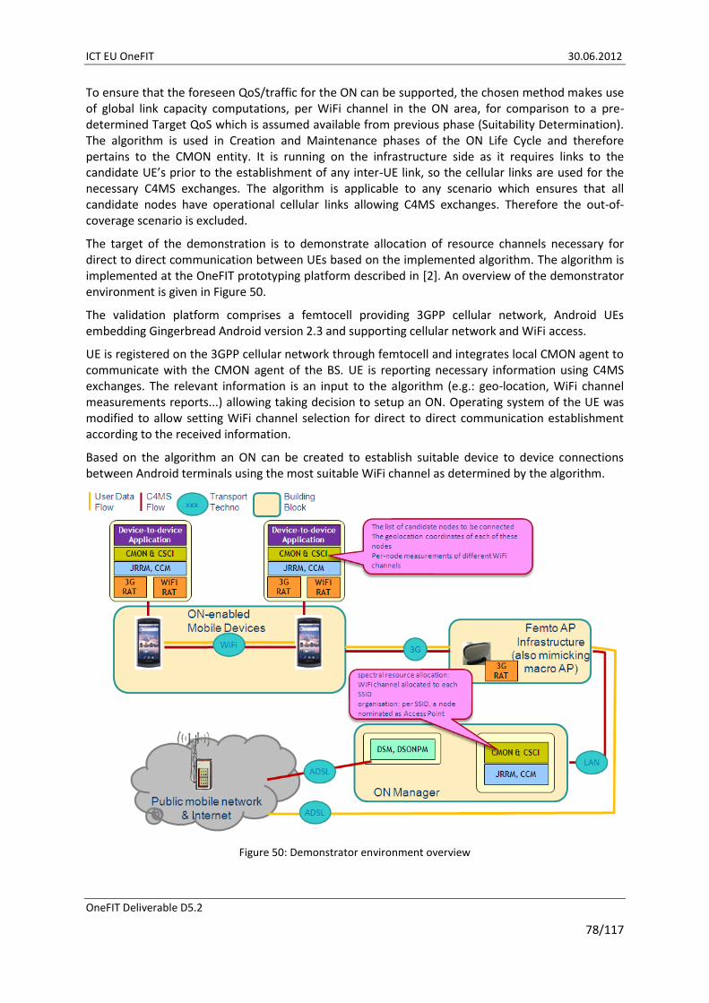
ICT EU OneFIT 30.06.2012
OneFIT Deliverable D5.2
78/117
To ensure that the foreseen QoS/traffic for the ON can be supported, the chosen method makes use of global link capacity computations, per WiFi channel in the ON area, for comparison to a pre-determined Target QoS which is assumed available from previous phase (Suitability Determination). The algorithm is used in Creation and Maintenance phases of the ON Life Cycle and therefore pertains to the CMON entity. It is running on the infrastructure side as it requires links to the candidate UE’s prior to the establishment of any inter-UE link, so the cellular links are used for the necessary C4MS exchanges. The algorithm is applicable to any scenario which ensures that all candidate nodes have operational cellular links allowing C4MS exchanges. Therefore the out-of-coverage scenario is excluded.
The target of the demonstration is to demonstrate allocation of resource channels necessary for direct to direct communication between UEs based on the implemented algorithm. The algorithm is implemented at the OneFIT prototyping platform described in [2]. An overview of the demonstrator environment is given in Figure 50.
The validation platform comprises a femtocell providing 3GPP cellular network, Android UEs embedding Gingerbread Android version 2.3 and supporting cellular network and WiFi access.
UE is registered on the 3GPP cellular network through femtocell and integrates local CMON agent to communicate with the CMON agent of the BS. UE is reporting necessary information using C4MS exchanges. The relevant information is an input to the algorithm (e.g.: geo-location, WiFi channel measurements reports...) allowing taking decision to setup an ON. Operating system of the UE was modified to allow setting WiFi channel selection for direct to direct communication establishment according to the received information.
Based on the algorithm an ON can be created to establish suitable device to device connections between Android terminals using the most suitable WiFi channel as determined by the algorithm.
Figure 50: Demonstrator environment overview

ICT EU OneFIT 30.06.2012
OneFIT Deliverable D5.2
79/117
3.3.3 ON maintenance and termination
This section presents the implementation of the ON maintenance and termination stages in the different elements of the demonstration platform. In some of the cases, the implementation is the same as in the ON suitability determination or the ON creation stages. In such cases, just a reference to the previous section has been given. Specific implementations are given for the spectrum opportunity identification and selection test-bed and for the application cognitive multi-path routing in wireless mesh networks.
3.3.3.1 Spectrum Opportunity Identification and Selection
During the lifetime of the established radio link between both devices, context changes might occur that makes the ON to be reconfigured in order to keep fulfilling its objective. Figure 51 describes the MSC of an ON reconfiguration process that could take place during the ON maintenance phase as will be shown in the demonstration in the context of the Spectrum Opportunity Identification and Selection test-bed presented in section 2.8. The description of the different steps is as follows:
1. UE#1 detects that the radio link is not performing as expected. In the demonstration, this will be due to interference generated in the spectrum currently in use in the radio link connecting UE#1 and UE#2;
2. As in the creation phase, it’s considered that ON operational policies dictate that the direct link establishment can be assisted by the infrastructure so that a MIH_C4MS_ONN.request is sent from UE#1 to the infrastructure. This message will indicate the reason (low link quality level), the ON identifier and the required QoS in terms of bit rate.
3. Also as in the creation phase, CSCI/CMON entities in the BS may need to refresh spectrum availability information and determine to send an inquiry to the Dynamic Spectrum Management (DSM) entity, triggering the spectrum opportunity identification;
4. DSM reply provides the CSCI/CMON entities in the BS with the available spectrum blocks at this time. Based on this information, the selection of new spectrum blocks to carry out the transmission will be performed.
5. The new proposed ON configuration in terms of selected spectrum is transferred to UE#1 by issuing a MIH_C4MS_ONN.response message;
6. UE#1 sends a MIH_C4MS_ONM.request message (ON-Modification) towards UE#2 with the new ON configuration;
7. UE#2 replies with a MIH_C4MS_ONM.response message where a successful result-code is reported to indicate that the terminal is ready to reconfigure the link with the proposed settings;
8. The link is reconfigured at this step;
9. Finally, the modification of the ON is notified to the infrastructure from UE#1 by sending a MIH MIH_C4MS_ONSN.indication message.
From an algorithmic perspective, the spectrum opportunity identification algorithm used in the ON maintenance stage is the same that was described in section 3.3.2.1. Similarly, the spectrum selection algorithm is also described in section 3.3.2.1, but, as a difference from the ON creation stage, in the ON maintenance case the trigger of the algorithm occurs whenever some changes are identified in the environment such as bad channel quality experienced by an active link or a link release while there are other active links. In these two cases, the algorithm makes decisions on spectrum mobility to modify the current spectrum block allocated to an active link. Like during the

ICT EU OneFIT 30.06.2012
OneFIT Deliverable D5.2
80/117
ON creation, the spectrum selection algorithm takes as input the list of available spectrum blocks provided by the spectrum opportunity identification, the bit rate requirements of the link to be assigned, the list of current assignments and a database with different statistics capturing the historical evolution of the fittingness factor based on measurements. The algorithm output is the list of spectrum assignments to each of the existing links.
Figure 51: Implemented message exchange for the ON modification.
3.3.3.2 Route pattern selection in ad-hoc networks
The algorithm presented in section 3.3.1.4 in the framework of ON suitability determination stage is also applicable during the ON maintenance (for more details about the algorithm please refer to D4.2 [9]).
3.3.3.3 Multi-flow routes co-determination
The algorithm presented in section 3.3.2.5 in the framework of ON creation stage is also applicable during the ON maintenance (for more details about the algorithm please refer to D4.2 [9]).
3.3.3.4 QoS and spectrum – aware routing techniques
The algorithm presented in section 3.3.2.6 in the framework of ON creation stage is also applicable during the ON maintenance (for more details about the algorithm please refer to D4.2 [9]).

ICT EU OneFIT 30.06.2012
OneFIT Deliverable D5.2
81/117
3.3.3.5 Application cognitive multi-path routing in wireless mesh networks
The application cognitive multi path routing algorithm for WMNs also performs the ON maintenance phase of the ON management cycle. The monitoring system continues to fill the contextual database which is constantly inspected by the algorithm. When QoS capabilities of the formed multiple paths drop below the QoS requirements dictated by the used applications, then the suitability determination starts once again in order to try and find the new, appropriate set of multiple paths which will satisfy the QoS requirements. If the need for reconfiguration of the existing ON is detected, after the successful suitability determination phase the creation of new set of multiple paths will be performed in the same way as described in 3.3.2.7. Some of the backhaul wireless links will be terminated in order to establish the new ones for enabling the new, updated set of multiple paths. The same process takes place when the need for termination of the ON is detected. The termination process will start when the ON (all possibilities for multiple paths) cannot provide the required level of QoS. This is done in order to remove the burden from the management system, decrease the interference between backhaul paths and avoid problems of packet reordering. The ON is also terminated when there is no longer a need for backhaul bandwidth aggregation or when the QoS requirements are relaxed. Before the termination process, the paths in the multiple paths set are inspected in order to determine which one is the most suitable to work on its own (transports the most of the current load, has the best QoS capabilities and imposes the least interference to the rest of the backhaul mesh network). The algorithm performs the termination process by sending the following commands in a form of TCP messages:
Disable the radio interface (logically by informing the OpenWRT system and physically by turning down it power);
Logically turn off the mesh mode of the interface;
Restart the OLSR daemon on the WMN AP in order to update the routing tables (remove entries).
This reconfiguration needs to be performed on all of the interfaces forming the links which are selected for termination.
After the termination process the OLSR single path routing is running normally.
3.3.3.6 UE-to-UE trusted direct path
The algorithm presented in section 3.3.3.6 in the framework of ON creation stage is also applicable during the ON maintenance (for more details about the algorithm please refer to D4.2 [9]).
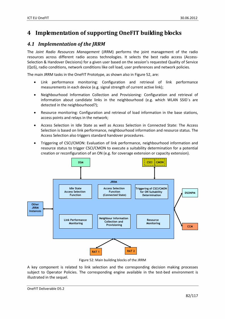
ICT EU OneFIT 30.06.2012
OneFIT Deliverable D5.2
82/117
4 Implementation of supporting OneFIT building blocks
4.1 Implementation of the JRRM
The Joint Radio Resources Management (JRRM) performs the joint management of the radio resources across different radio access technologies. It selects the best radio access (Access-Selection & Handover Decisions) for a given user based on the session’s requested Quality of Service (QoS), radio conditions, network conditions like cell load, user preferences and network policies.
The main JRRM tasks in the OneFIT Prototype, as shown also in Figure 52, are:
Link performance monitoring: Configuration and retrieval of link performance measurements in each device (e.g. signal strength of current active link);
Neighbourhood Information Collection and Provisioning: Configuration and retrieval of information about candidate links in the neighbourhood (e.g. which WLAN SSID`s are detected in the neighbourhood?);
Resource monitoring: Configuration and retrieval of load information in the base stations, access points and relays in the network;
Access Selection in Idle State as well as Access Selection in Connected State: The Access Selection is based on link performance, neighbourhood information and resource status. The Access Selection also triggers standard handover procedures.
Triggering of CSCI/CMON: Evaluation of link performance, neighbourhood information and resource status to trigger CSCI/CMON to execute a suitability determination for a potential creation or reconfiguration of an ON (e.g. for coverage extension or capacity extension).
DSONPM
CSCI CMON
JRRM
DSM
RAT 1 RAT 2
CCM
Other
JRRM
Instances
Triggering of CSCI/CMON
for ON Suitability
Determination
Resource
Monitoring
Link Performance
Monitoring
Access Selection
Function
(Connected State)
Idle State
Access Selection
Function
Neighbour Information
Collection and
Provisioning
Figure 52: Main building blocks of the JRRM
A key component is related to link selection and the corresponding decision making processes subject to Operator Policies. The corresponding engine available in the test-bed environment is illustrated in the sequel.

ICT EU OneFIT 30.06.2012
OneFIT Deliverable D5.2
83/117
Database
Profile
Context (WLAN/ IMC 3G
Controller)
Knowledge
Decision
Policies
Enforcement (WLAN/ IMC 3G
Controller)
Figure 53: Link Selection Engine.
4.2 Implementation of the DSM
The main task of the Dynamic Spectrum Management is to decide on which spectrum to use in the different cells in the radio access networks including dynamic opportunistic cells.
Therefore, the DSM has knowledge on granted licenses, policies and on the current spectrum usage in the network.
Figure 54 shows an example of the GUI where at a selected geographical position three access points are using the ISM-band around 2.4 GHz.
Figure 54: GUI of the Dynamic Spectrum Management
Figure 55 shows the DSM with its external interfaces and its internal building blocks.
Users of the DSM like CSCI, CMON, JRRM and DSONPM provide information to the DSM on the current configuration of the network. Further on, these building blocks shall ask the DSM for the creation of new cells on which spectrum to use for these cells. The DSM then provides then one or more options on which spectrum to use for these cells. After creation of such a cell, the DSM is then informed about the actual spectrum usage of these cells. The DSM is also informed in the case that a cell is switched off, e.g. to save energy or because an ON is released.
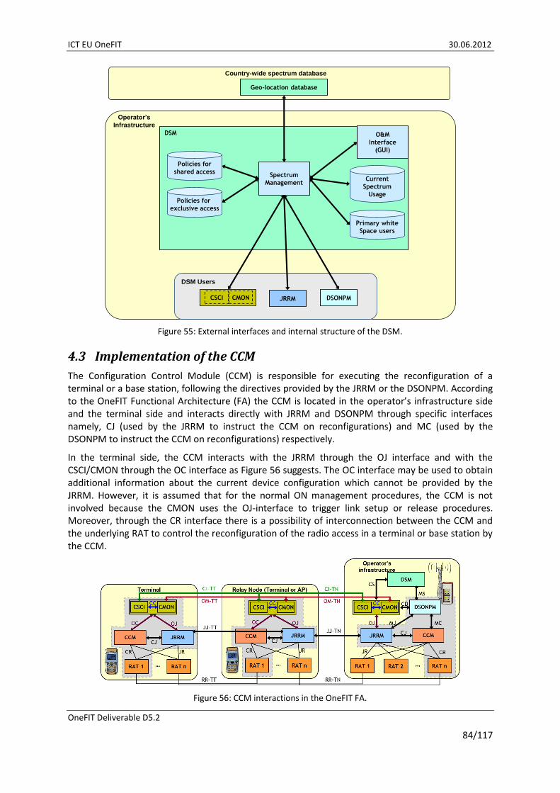
ICT EU OneFIT 30.06.2012
OneFIT Deliverable D5.2
84/117
DSM Users
DSM
DSONPM
Operator’s
Infrastructure
Country-wide spectrum database
Geo-location database
CSCI CMON
O&M
Interface
(GUI)
Policies for
shared accessCurrent
Spectrum
Usage
Spectrum
Management
Policies for
exclusive access
Primary white
Space users
JRRM
Figure 55: External interfaces and internal structure of the DSM.
4.3 Implementation of the CCM
The Configuration Control Module (CCM) is responsible for executing the reconfiguration of a terminal or a base station, following the directives provided by the JRRM or the DSONPM. According to the OneFIT Functional Architecture (FA) the CCM is located in the operator’s infrastructure side and the terminal side and interacts directly with JRRM and DSONPM through specific interfaces namely, CJ (used by the JRRM to instruct the CCM on reconfigurations) and MC (used by the DSONPM to instruct the CCM on reconfigurations) respectively.
In the terminal side, the CCM interacts with the JRRM through the OJ interface and with the CSCI/CMON through the OC interface as Figure 56 suggests. The OC interface may be used to obtain additional information about the current device configuration which cannot be provided by the JRRM. However, it is assumed that for the normal ON management procedures, the CCM is not involved because the CMON uses the OJ-interface to trigger link setup or release procedures. Moreover, through the CR interface there is a possibility of interconnection between the CCM and the underlying RAT to control the reconfiguration of the radio access in a terminal or base station by the CCM.
Figure 56: CCM interactions in the OneFIT FA.

ICT EU OneFIT 30.06.2012
OneFIT Deliverable D5.2
85/117
4.4 Implementation of the DSONPM
The main aim of the Dynamic Self-Organizing Network Planning and Management (DSONPM) is to provide to the ON the necessary management functionalities of the infrastructure entities in order to proceed to necessary decision making on which solution is most appropriate to be enforced.
Specifically, as soon as an infrastructure element (e.g. a macro BS) experiences a problematic situation (e.g. congestion due to heavy load), the DSONPM is the functional entity of the FA, which will be notified and will be responsible for the designation of the solution which will be followed.
In order to achieve this goal, a specific procedure has been defined in OneFIT, according to which some necessary steps are identified. As Figure 58 suggests, a specific sequence of messages takes place in order to reach the “Decision for solving the situation”. In the initialization phase of the validation platform each infrastructure element registers to the DSONPM as Figure 57 illustrates.
Figure 57: Registered infrastructure elements at DSONPM.
Initially the congestion situation is identified by a BS (e.g. BS1) and a message is sent to the DSONPM entity. This message informs the DSONPM about the congestion of BS1 and sends the current context (including load) of the BS1 to the DSONPM. The DSONPM sends a message to neighbouring, available BS(s) (e.g. BS2 or more), in order to request their current context. BS2 responds with its context (including its current load), in order to provide the necessary input to the DSONPM for the decision making. As soon as the DSONPM has acquired necessary information from available infrastructure elements, it is ready for the decision making process. When the decision is reached, the DSONPM shall send a message back to the congested BS (BS1) with the acquired context of the available BSs in order to start the problem resolution according to the designated decision.
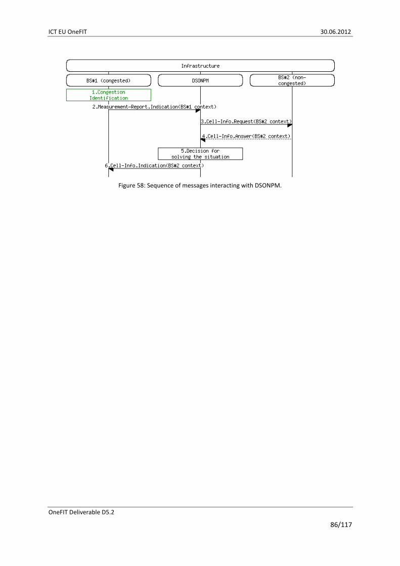
ICT EU OneFIT 30.06.2012
OneFIT Deliverable D5.2
86/117
Figure 58: Sequence of messages interacting with DSONPM.

ICT EU OneFIT 30.06.2012
OneFIT Deliverable D5.2
87/117
5 Implementation of the C4MS protocol The Control Channels for the Cooperation of Cognitive Management Systems (C4MS) are used to transport the protocol information needed for the management of opportunistic networks (ONs). The information exchanged over C4MS is used for the realization of suitability determination, creation, maintenance and termination of Opportunistic Networks.
Control Information for the Management of Cognitive Radio Systems needs to be distributed in different phases of the connectivity (i.e. before a connection is established, after a connection has been established), using different distribution mechanisms (Unicast, multicast, broadcast) and the data must be exchanged between different types of nodes (between terminals/Device-to-Device communication, between terminals and the radio access network, inside a radio access network e.g. between Base Station and a Central Control Point or a database).
As a single C4MS implementation solution does not support all these different aspects [10], the C4MS implementation is based on a combination of different radio independent and radio dependent solutions.
The following subsections describe the different implementation options used in the OneFIT prototyping and validation activities and the purpose they are used for.
5.1 IEEE 802.21 for device-to-device and terminal-network communication
IEEE 802.21 is a standard on “Media-Independent Handover (MIH) Services” [14] which defines a protocol and mechanisms to enable handover and interoperability between heterogeneous network types including both 802 and non 802 networks.
As this protocol can be used on top of different radio access technologies and because it is easily extensible, IEEE 802.21 has been selected as one of the base protocols to be extended with functionalities for the management of opportunistic networks.
An example C4MS message as used in the opportunistic networking demonstrator (see section 2.2) is shown in Figure 59.
This prototype described in section 2.2 is also used for the C4MS protocol signalling evaluation. Therefore, the number of transferred C4MS messages and bytes are measured as shown in Figure 60. The results of the signalling evaluation are described in detail in D3.3 [7]. One result, the number of C4MS per second for a basic ON (one device going out of coverage, one device providing the relaying service, one infrastructure network) is also shown in Figure 61. A large part of the ON related signalling is caused by the exchange of link measurements during the lifetime of an ON. The messages for ON negotiation, creation and release have the average number of C4MS per second mainly for ONs with small duration, e.g. less than 2 minutes.
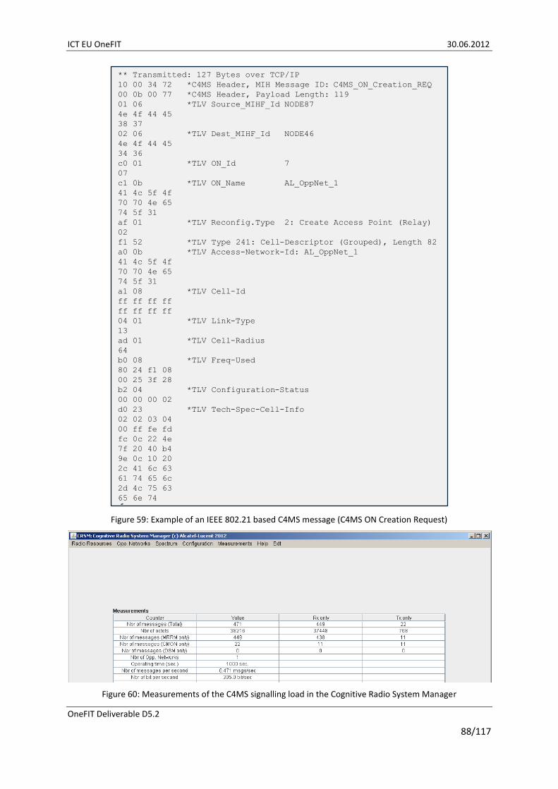
ICT EU OneFIT 30.06.2012
OneFIT Deliverable D5.2
88/117
** Transmitted: 127 Bytes over TCP/IP
10 00 34 72 *C4MS Header, MIH Message ID: C4MS_ON_Creation_REQ
00 0b 00 77 *C4MS Header, Payload Length: 119
01 06 *TLV Source_MIHF_Id NODE87
4e 4f 44 45
38 37
02 06 *TLV Dest_MIHF_Id NODE46
4e 4f 44 45
34 36
c0 01 *TLV ON_Id 7
07
c1 0b *TLV ON_Name AL_OppNet_1
41 4c 5f 4f
70 70 4e 65
74 5f 31
af 01 *TLV Reconfig.Type 2: Create Access Point (Relay)
02
f1 52 *TLV Type 241: Cell-Descriptor (Grouped), Length 82
a0 0b *TLV Access-Network-Id: AL_OppNet_1
41 4c 5f 4f
70 70 4e 65
74 5f 31
a1 08 *TLV Cell-Id
ff ff ff ff
ff ff ff ff
04 01 *TLV Link-Type
13
ad 01 *TLV Cell-Radius
64
b0 08 *TLV Freq-Used
80 24 f1 08
00 25 3f 28
b2 04 *TLV Configuration-Status
00 00 00 02
d0 23 *TLV Tech-Spec-Cell-Info
02 02 03 04
00 ff fe fd
fc 0c 22 4e
7f 20 40 b4
9e 0c 10 20
2c 41 6c 63
61 74 65 6c
2d 4c 75 63
65 6e 74
Figure 59: Example of an IEEE 802.21 based C4MS message (C4MS ON Creation Request)
Figure 60: Measurements of the C4MS signalling load in the Cognitive Radio System Manager

ICT EU OneFIT 30.06.2012
OneFIT Deliverable D5.2
89/117
0
0,05
0,1
0,15
0,2
0,25
0,3
0,35
0,4
0,45
0,5
1 2 3 4 5 6 7 8 9 10 11 12 13 14 15
Nu
mb
er
of
C4
MS
Me
ssag
es
ON Duration (Minutes)
Number of C4MS Messages per Second
Messages per second (Link report all 5 sec)
Messages per second (Link report all 30 sec)
Figure 61: Number of C4MS messages for an ON dependent on the ON duration
5.1.1 IEEE 802.21 based C4MS protocol overview
In the prototype, the 802.21 based C4MS messages are transported via TCP/IP and as default the TCP port 4551 is used. The alternatively allowed use of UDP is not supported in the prototype.
In general, an 802.21 based C4MS message consists of
A protocol header with 8 byte length;
A source identifier (802.21 Source MIHF identifier);
A destination identifier (802.21 Destination MIHF identifier);
Zero, one or more parameters.
5.1.2 IEEE 802.21 protocol header format
A summary of the MIH Protocol Header format [14] is shown below:
0 1 2 3
0 1 2 3 4 5 6 7 8 9 0 1 2 3 4 5 6 7 8 9 0 1 2 3 4 5 6 7 8 9 0 1
+-+-+-+-+-+-+-+-+-+-+-+-+-+-+-+-+-+-+-+-+-+-+-+-+-+-+-+-+-+-+-+-+
|Version|A|S|U|M| FragmentNbr |r| MIH Message ID |
| | | | | | | | SID | Op| AID |
+-+-+-+-+-+-+-+-+-+-+-+-+-+-+-+-+-+-+-+-+-+-+-+-+-+-+-+-+-+-+-+-+
|r r r r| Transaction ID | Variable Payload Length |
| | | |
+-+-+-+-+-+-+-+-+-+-+-+-+-+-+-+-+-+-+-+-+-+-+-+-+-+-+-+-+-+-+-+-+
Version: The protocol version is set to 1;
A: This field requests an acknowledgement of the message;
S: This field is used for responding to the request for an ACK of the message;
U: Unauthenticated information request (flag not used in the prototype);
M: More fragment flag (flag not used in the prototype);
FragmentNbr: The fragment number is always set to 0 in the prototype;

ICT EU OneFIT 30.06.2012
OneFIT Deliverable D5.2
90/117
SID: The Service Identifier of the Message Id, e.g. 10 for Event Service;
Op: The Opcode of the Message Id, Values: 01=Request, 10=Response, 11=Indication;
AID: Action Identifier, e.g. for Link Down or ON Creation;
MIH Message ID: Combines SID, Op and AID, for example value 0x2C02 = MIH Link Up Indication value 0x3472 = ON Creation.Request value 0x3872 = ON Creation.Response;
r: Reserved;
Transaction Id: This field is used for matching Requests and Responses;
Variable Payload Length: Indicates the length of the variable payload (Message length without header).
5.1.3 IEEE 802.21 parameter format
The parameters are encoded in the Type-Length-Value (TLV) format as shown below:
0 1 2 3
0 1 2 3 4 5 6 7 8 9 0 1 2 3 4 5 6 7 8 9 0 1 2 3 4 5 6 7 8 9 0 1
+-+-+-+-+-+-+-+-+-+-+-+-+-+-+-+-+-+-+-+-+-+-+-+-+-+-+-+-+-+-+-+-+
| Type | Length (of V.)| Value |
+-+-+-+-+-+-+-+-+-+-+-+-+-+-+-+-+-+-+-+-+-+-+-+-+-+-+-+-+-+-+-+-+
| ... |
+-+-+-+-+-+-+-+-+-+-+-+-+-+-+-+-+-+-+-+-+-+-+-+-+-+-+-+-+-+-+-+-+
Type: The type of the parameter, e.g. 01 = Source MIHF Id, 02 = Destination MIHF Id, 03 = Status, 04 = Link type;
Length: This field requests an acknowledgement of the message;
Value: This field is used for responding to the request for an ACK of the message.
5.1.4 Procedures and messages
5.1.4.1 Link events
Different types of link events are reported from a terminal to the base station / access point or to the next relay. Relays also send link events to the base station / access point or towards the next relay. The following link events are reported:
Link_Detected: A link to another access point is detected;
Link_Up: A L2 connection is established;
Link_Going_Down: The link conditions are degrading and connection loss is imminent;
Link_Down: A L2 connection is broken;
Link_Parameters_Report: A link parameter has crossed a pre-specified threshold.
The MIH_Link_Up.indication for example uses the following message format:
<MIH_Link_Up.Indiation> ::

ICT EU OneFIT 30.06.2012
OneFIT Deliverable D5.2
91/117
= < Message Type: 0x2C02>
{ Source MIHF ID}
{ Destination MIHF ID}
{ Terminal-Capabilities}
* { LinkIdAndParam}
Please note that this format has some differences to the MIH_Link_Up Indication as specified by IEEE 802.21 section 8.6.2.2:
The Terminal Capabilities parameter is not specified in 802.21. This parameter is needed in certain scenarios for the support of the ON_Negotiation procedure, see section 5.1.4.2 below.
The LinkIdAndParam (Link parameter report list TLV) is according 802.21 used in the MIH_Link_Parameters_Report.indication but not in the MIH_Link_Up.indication while in the prototype, this parameter is also used in the MIH_Link_Up.indication.
5.1.4.2 Intrinsic ON Negotiation support
In the 802.21 based C4MS implementation, no dedicated ON Negotiation messages have been implemented because the information needed for the negotiation can already be transported intrinsic within other messages which are already exchanged by standard procedures.
The information needed for the negotiation process consists of terminal capabilities, user preferences and desired QoS. This information is either exchanged via existing session setup procedures or this information is included as a protocol extension in other messages.
In the 802.21 based C4MS implementation, the terminal capabilities are transported in the MIH_Link_Up.indication (see section 5.1.4.1 above).
The Terminal-Capabilities Parameter has been implemented as a bitmap where each bit can indication certain capabilities.
Several bits are used to indicate which radio access technologies are supported, e.g. GSM, GPRS, EDGE, Fixed/Ethernet, IEEE 802.11 WLAN, UMTS and LTE.
Further bits are used to indicate relaying capabilities:
Indicator if the device supports RELAYING of IEEE 802.11 WLAN;
Indicator if the device supports RELAYING of UMTS;
Indicator if the device supports RELAYING of LTE;
Indicator if the device supports RELAYING between different technologies.
5.1.4.3 ON Creation by Device Reconfiguration
In several Opportunistic Networking scenarios a device must be reconfigured in order that an ON can be created. For example, a new Access Point must be created and a Relaying Function must be activated or a Femto-Cell must be reconfigured to support other users or user groups. In other cases, a Base Station may have to be waked from a power-save mode or the cell reconfiguration may have to be changed.
For such an ON-Creation by Device Reconfiguration, a procedure as shown in the example below can be used:

ICT EU OneFIT 30.06.2012
OneFIT Deliverable D5.2
92/117
Node 1 Node 2
| |
|-- ON-Creation.Request (ONCR)------------------------------------------->|
| - Source_MIHF_Id |
| - Destination_MIHF_Id |
| - ON_Id |
| - ON_Name |
| - Reconfiguration-Type (Create Cell and relay traffic) |
| - Cell-Descriptor (Access-Network-Id, Cell-Id, Link-Type, |
| Frequency-Used) |
| |
|<- ON-Creation.Answer (ONCA)---------------------------------------------|
| - Status |
| |
Figure 62: ON-Creation by Reconfiguration procedure
The ON-Creation.Request contains an indicator for the type of the reconfiguration (e.g. indication that a new cell/access point shall be created and that the traffic shall be relayed) and further on a description of the new configuration. In the prototype, this descriptor consists of the so called “Cell-Descriptor” which describes the Access-Network-Id (e.g. the WLAN SSID or the UMTS/LTE PLMN Identity), the Cell-Id (e.g. the WLAN BSSID or the UMTS/LTE Cell identity), the Link-Type describing the Radio Access Technology (e.g. WLAN or LTE) and the Frequency or Frequencies to be used.
The ON-Creation.Answer either indicates the success or the failure of the operation. In the failure case, a description of the failure is added. Based on such a failure description, it can be decided to abandon the reconfiguration or to try to reconfigure the device with a different set of parameters.
5.1.4.4 ON Suitability indication
The ON Suitability procedure is used to determine the suitability of an ON at a specific time and place based on the observed radio environment and some established criteria.
To support this ON Suitability procedure, an ON-Suitability.indication message can be sent from one node to another to initiate a suitability determination procedure in that node.
As an example, after the setup of a new access point in the network, a first node (Node 1 in Figure 63) informs a second a node that it may now be suitable to use a new cell/access point as described in the cell descriptor.
Node 1 Node 2
| |
|-- ON_Suitability.Indication (ONSI)------------------------------------->|
| - Source_MIHF_Id |
| - Destination_MIHF_Id |
| - ON_Id |
| - ON_Name |
| - Cell-Descriptor (Access-Network-Id, Cell-Id, Link-Type, |
| Frequency-Used) |
| - ... |
Figure 63: ON Suitability indication
Based on this information, the second node can then start a discovery procedure for the described access or cell. Based on the result of the suitability and discovery procedure, this may then lead to a handover to the new access or cell.

ICT EU OneFIT 30.06.2012
OneFIT Deliverable D5.2
93/117
5.1.4.5 ON Release
When an ON is no longer needed, the links between the nodes in the ON can then be released, e.g. via normal release procedures. This is usually combined with a handover e.g. back to the infrastructure.
Further on, Access points which have been created for the support of the ON but which are no longer needed can then be disabled with a reconfiguration procedure as shown in Figure 64. Any relaying function for the traffic of that cell will then also be disabled.
Node 1 Node 2
| |
|-- ON-Release-Request(ONRR)--------------------------------------------->|
| - Source_MIHF_Id |
| - Destinatino_MIHF_Id |
| - ON_Id |
| - ON_Name |
| - Reconfiguration-Type (Disable cell) |
| - Cell-Descriptor (Access-Network-Id, Cell-Id, Link-Type) |
| |
|<- ON-Release-Answer(ONRA)-----------------------------------------------|
| - Status |
| |
Figure 64: ON-Release by Reconfiguration of a device to shut down a cell and the corresponding relaying function
5.2 IETF OLSR for route discovery and management
Optimized Link State Routing Protocol (OLSR) is an IP routing protocol optimized for mobile ad-hoc networks, which can also be used on other wireless ad-hoc networks. OLSR is one of the main internet standards for mesh networks and it is widely used and well tested. It was shown that OLSR has high scalability; it uses very little CPU time and due to its high portability OLSR is used for routing in One Fit’s wireless mesh network test-bed. The IEEE802.11a protocol is used for node discovery, channel selection and link establishment in this test-bed. OLSR signal flows between nodes in this test-bed are presented in Figure 65.
The OLSR protocol is used to exchange information for the route discovery and management between the different open wireless mesh network routers. OLSR does not send data packets; it only sends its own messages such as TC, HELLO, HNA etc. These are sent, received and processed in order to find valid routes between network nodes. Once routes to all nodes in the network are discovered for a particular node, OLSR will simply set the corresponding kernel routing table entry. OLSR uses the UDP protocol for message exchange and runs on Layer 3.
Since there is not much dynamicity in the topology of WMNs, the OLSR signalling overhead can be significantly reduced when compared to the OLSR signalling in mobile ad-hoc networks with dynamic topology.
Nodes participating in an OLSR routing domain can be multi-homed. That means that they can run OLSR on multiple communication interfaces using multiple identifiers.

ICT EU OneFIT 30.06.2012
OneFIT Deliverable D5.2
94/117
Figure 65: Example of SNMP and OLSR signalling between WMN nodes and centralized management server
In a classic link-state algorithm, link-state information is flooded throughout the network (see Figure 66). OLSR uses this approach as well, but since the protocol runs in wireless multi-hop scenarios the message flooding in OLSR is optimized to preserve bandwidth (see Figure 67). The optimization is based on a technique called Multi Point Relaying.
OLSR defines three basic types of control messages:
HELLO - HELLO messages are transmitted to all neighbours. These messages are used for neighbour sensing and selection of Multi Point Relays (MPRs).
TC - Topology Control messages are the link state signalling done by OLSR. This messaging is optimized in several ways using MPRs.
MID - Multiple Interface Declaration messages are transmitted by nodes running OLSR on more than one interface. These messages list all IP addresses used by a node.
The concept of multipoint relaying is to reduce the number of duplicate retransmissions while forwarding a broadcast packet. This technique restricts the set of nodes retransmitting a packet from all nodes, to a subset of all nodes. The size of this subset depends on the topology of the network.
Reducing the control overhead of the routing protocol is achieved by selecting neighbours as multi point relays. Every node calculates its own set of MPRs as a subset of its symmetric neighbour nodes chosen so that all 2 hop neighbours can be reached through a MPR. This means that for every node n in the network that can be reached from the local node by at minimum two symmetric hops, there must exist a MPR m so that n has a symmetric link to m and m is a symmetric neighbour of the local node.

ICT EU OneFIT 30.06.2012
OneFIT Deliverable D5.2
95/117
Figure 66: Flooding a packet in a wireless multi hop network. The arrows show the way information is passed, not all transmissions.
Figure 67: Flooding a packet in a wireless multi hop network from the center node using MPRs (black). The arrows show the way information is passed, not all transmissions.
In Table 2 it is presented how different C4MS messages can be mapped onto the protocol specific messages of SNMP, OLSR protocol and IEEE802.11a. These protocols are used in OneFIT’s WMN test-bed (for validation of Scenario 5 specific use-cases) for gathering of contextual information and system monitoring (SNMP), route/topology discovery, establishment and maintenance (OLSR) and for providing MAC specific mechanisms (channel selection, node discovery, link establishment) (IEEE802.11a).
The OLSR routing protocol is used as the underlying single path routing protocol in the open platform WMN test-bed used for implementation and validation of the algorithms addressing the OneFIT scenario 5 use cases.

ICT EU OneFIT 30.06.2012
OneFIT Deliverable D5.2
96/117
Table 2: Mapping of C4MS messages on messages of protocols used in WMN management
C4MS messages SNMP messages OLSR messages 802.11a
Information-Request (INR) Get-request
Information-Answer (INA) Get-response
Information-Indication (INI) Trap
Node discovery Beacons/probe response
Node identification and selection
MID messages 802.11a
Spectrum opportunity identification and selection
802.11a
Route identification and selection
Hello messages, TC messages
ON-Suitability-Indication (ONSI)
Suitability determination and indication is done by a centralized controller
Trap
ON-Negotiation-Request (ONNR)
Negotiation request/answer messages are exchanged between node and centralized controller
Get-request/get-response
ON-Negotiation-Answer (ONNA)
Get-request/get-response
ON-Creation-Request (ONCR) Messages/commands over ssh (secure shell) from centralized controller to node
Set-request
ON-Creation-Answer (ONCA) Get-request/get-response
ON-Modification-Request (ONMR)
Messages/commands over ssh from centralized controller to node
Set-request
ON-Modification-Answer (ONMA)
Get-request/get-response

ICT EU OneFIT 30.06.2012
OneFIT Deliverable D5.2
97/117
ON-Release-Request (ONRR) Messages/commands over ssh from centralized controller to node
Set-request
ON-Release-Answer (ONRA) Get-request/get-response
ON-Status-Notification (ONSN)
Get-request/get-response
5.3 IETF SNMP for network management of infrastructure elements
The Simple Network Management Protocol (SNMP) is a simple request/response protocol in which SNMP manager communicates with SNMP agents using SNMP messages in which PDU (Packet Data Unit) are encapsulated (see Figure 68). A SNMP message consists of a sequence that contains a SNMP version, community string and the SNMP PDU which forms the body of message.
The SNMP protocol is used for WMN monitoring (contextual data gathering) in the open platform WMN test-bed which is used for implementation and validation of the algorithms addressing the OneFIT scenario 5 use cases.
The following messages are supported by the SNMPv2 protocol:
Get-request - Accesses and retrieves the value of one or more instances of management information.
Get-next-request - Accesses and retrieves the value of the next instance of management information in lexicographical order.
Get-bulk – Accesses multiple values at one time.
Get-response – Reply to a Get-request, Get-next-request and Set-request operations.
Set-request – Stores and sets a value in variable.
Trap – An unsolicited message that is sent by an SNMP agent to an SNMP manager and indicates that some event has occurred.
Figure 68: Exchange of messages between SNMP management system and SNMP agent
As an example of infrastructure elements, we will consider wireless mesh network (WMN) nodes. Relevant contextual information is gathered from these nodes by using the SNMPv2.
Contextual data include standard info which is obtainable with this protocol:
Interface related information: SINR, channel used, inbound/outbound packet count, packet drop count, MAC address of the interface with which the link is established;

ICT EU OneFIT 30.06.2012
OneFIT Deliverable D5.2
98/117
Node related information: power consumption, CPU load, routing table, cache storage status (size, free space).
Information regarding which WMN node supports ONs is considered as known, because only infrastructure nodes are forming these ONs (we consider that operators know ON capabilities of their equipment).
A centralized decision making process is responsible for associating nodes with existing ONs and creation of new ONs. Whether or not a particular WMN node participates in any of the existing ONs can be obtained over the SNMPv2 protocol, but it can also be considered as known.
These contextual data are sent from WMN nodes to centralized decision making and monitoring controller/server (see Figure 65).
The mapping of C4MS messages onto the SNMP specific messages is presented in Table 2.

ICT EU OneFIT 30.06.2012
OneFIT Deliverable D5.2
99/117
6 Implementation of the OneFIT scenarios Five OneFIT scenarios are defined in the D2.1 [3]. These scenarios are:
Scenario 1: Opportunistic coverage extension;
Scenario 2: Opportunistic capacity extension;
Scenario 3: Infrastructure supported opportunistic device-to-device networking;
Scenario 4: Opportunistic traffic aggregation in the radio access network;
Scenario 5: Opportunistic resource aggregation in the backhaul network.
Different use cases of scenarios 1, 2, 3 and 5 are implemented and validated in the OneFIT validation platform. The test-beds, which are described in section 2, are utilized in implementation of different scenarios.
Implementation of the scenario 1 utilizes the following test-beds:
Prototyping platform for the management of opportunistic networks (section 2.1);
Opportunistic Networking Demonstrator (section 2.2);
Opportunistic ad-hoc network demonstrator (section 2.4);
Prototyping Platform for Opportunistic Coverage Extension and related Support Functions (section 2.5);
Cognitive radio test-bed (section 2.7).
Implementation of the scenario 2 utilizes the following test-beds:
Prototyping platform for the management of opportunistic networks (section 2.1);
Opportunistic networking demonstrator (section 2.2);
Opportunistic ad-hoc network demonstrator (section 2.4).
Implementation of the scenario 3 utilizes the following test-beds:
Direct D2D communication test-bed (section 2.6);
Opportunistic service provision demonstrator (section 2.3);
Opportunistic ad-hoc network demonstrator (section 2.4);
Spectrum opportunity identification and spectrum selection test-bed (section 2.8).
Implementation of the scenario 5 use case utilizes the following test-bed:
Open platform wireless mesh network test-bed (section 2.9).
Some of these scenario implementations are still in progress and will be presented in D5.3 due for December 2012. Those scenario implementations which are already validated and successfully demonstrated are described in the following.
The implemented WP4 algorithms provide the building blocks for ON management systems. Mapping of these algorithms onto the OneFIT scenarios is given in Figure 32.

ICT EU OneFIT 30.06.2012
OneFIT Deliverable D5.2
100/117
6.1 Implementation of the OneFIT scenario 1 “Opportunistic coverage extension”
The scenario 1 is about opportunistic coverage extension and the main goal of the scenario is to create ONs in areas where coverage of the infrastructure is insufficient or terminals cannot connect to the infrastructure due to a RAT mismatch. The operator-governed ONs will enable the non-connected terminals to gain access to the infrastructure through intermediate nodes.
For more information regarding definition of the scenario and description of use cases please refer to D2.1 [3].
6.1.1 Sub-scenario: Device going out of coverage
A first implemented coverage extension scenario is the case where a device is first directly connected with infrastructure, but due to mobility of the user, the user is moving out of coverage of the infrastructure. The solution is to create an ON for coverage extension as shown in the message sequence chart in Figure 69. This scenario is implemented in the opportunistic networking demonstrator described in section 2.2 on page 25.
6.1.2 Sub-scenario: Device cannot connect to infrastructure
In this scenario, a device is switched on and cannot find an access point or a base station of the infrastructure or the device has already moved out of the infrastructure coverage. To solve this situation, the device being out of coverage starts a discovery procedure to detect other devices in its neighbourhood. If such a device is found – as shown in the message sequence chart (MSC) in Figure 70 – the suitability determination, negotiation and ON creation tasks are then performed. When the ON is created, the device being out of direct infrastructure coverage is then served via another device proving a relaying service.
This scenario can also be applied to the case where a macro BS experiences failure. As a result, mobile devices are left without coverage. ON is started forming up by collaboration of CSCIs and CMONs in order to serve the out of infrastructure terminals. Mobile devices are connected to each other in order to gain access to the infrastructure.
When the previously failed macro BS goes back online, ON is not needed anymore and it is terminated.
Further descriptions on the MSCs are also documented in [3]. Moreover, C4MS messages are exchanged by using the FIPA Agent Communication Language (ACL) messages. So, through the JADE platform which is agent-based, messages are transferred between various functional entities (e.g., CSCI, CMON, and DSONPM) according to the predefined MSCs.
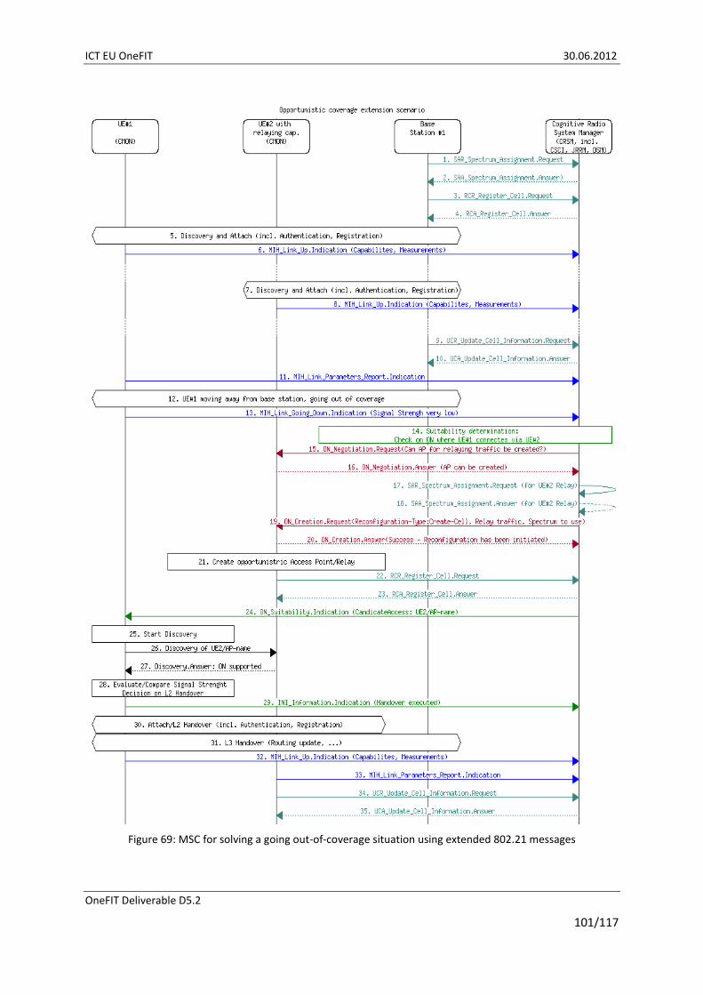
ICT EU OneFIT 30.06.2012
OneFIT Deliverable D5.2
101/117
Figure 69: MSC for solving a going out-of-coverage situation using extended 802.21 messages

ICT EU OneFIT 30.06.2012
OneFIT Deliverable D5.2
102/117
Figure 70: Coverage extension procedure
For showcasing key-features from a Mobile Device / Terminal perspective, the Prototyping Platform for Opportunistic Coverage Extension and related Support Functions as introduced in section 2.5 is built such that it can be suitably reconfigured to the following configurations:
i. Provision of wireless services in a dense neighbourhood environment building on non-interfering Radio Access Technology.
This configuration represents the performance reference case with no interference, congestion, etc. occurring. In particular, mobile devices are communicating directly with a Femto/Macro BS and a WiFi AP respectively.

ICT EU OneFIT 30.06.2012
OneFIT Deliverable D5.2
103/117
Figure 71: Basic Reference architecture of Prototyping Platform for Opportunistic Coverage Extension and related Support Functions
ii. Provision of wireless services in a dense neighbourhood environment employing an Opportunistic Network for ensuring access for a WiFi-only Terminal Device.
In one part of the dense neighbourhood environment, an Opportunistic Network is set-up in order to ensure internet access for a WiFi-only Terminal Device. Without the corresponding Opportunistic Network feature, the concerned Terminal would not be able to access internet, since both illustrated domains (“Apartment A” and “Apartment B”) are considered to be closed.
Figure 72: Architecture of Prototyping Platform for Opportunistic Coverage Extension and related Support Functions including an Opportunistic Network Configuration
iii. Provision of wireless services in a dense neighbourhood environment employing automized network reconfiguration and an Opportunistic Network for ensuring access for a WiFi-only Terminal Device.
A complex wireless networking environment is considered in a dense neighbourhood. It is expected that non-expert users will constantly add wireless devices in their respective domains. Improperly configured devices may indeed lead to congestion/interference events and thus to poor QoS for concerned users. In this configuration of the test-bed, such congestion case is shown and the network is correspondingly reconfigured employing suitable Opportunistic Network configurations. Finally, QoS is maintained within the concerned environment.
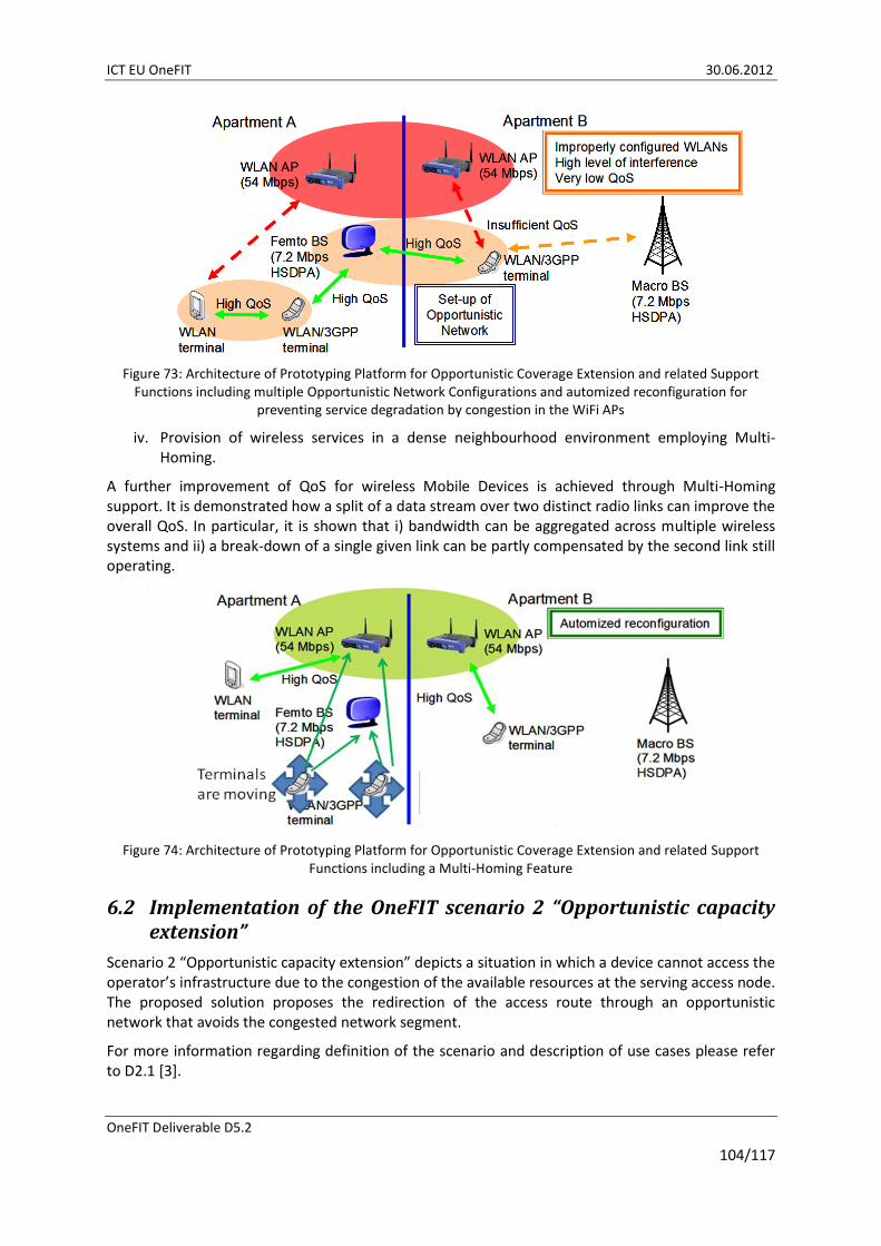
ICT EU OneFIT 30.06.2012
OneFIT Deliverable D5.2
104/117
Figure 73: Architecture of Prototyping Platform for Opportunistic Coverage Extension and related Support Functions including multiple Opportunistic Network Configurations and automized reconfiguration for
preventing service degradation by congestion in the WiFi APs
iv. Provision of wireless services in a dense neighbourhood environment employing Multi-Homing.
A further improvement of QoS for wireless Mobile Devices is achieved through Multi-Homing support. It is demonstrated how a split of a data stream over two distinct radio links can improve the overall QoS. In particular, it is shown that i) bandwidth can be aggregated across multiple wireless systems and ii) a break-down of a single given link can be partly compensated by the second link still operating.
Figure 74: Architecture of Prototyping Platform for Opportunistic Coverage Extension and related Support Functions including a Multi-Homing Feature
6.2 Implementation of the OneFIT scenario 2 “Opportunistic capacity extension”
Scenario 2 “Opportunistic capacity extension” depicts a situation in which a device cannot access the operator’s infrastructure due to the congestion of the available resources at the serving access node. The proposed solution proposes the redirection of the access route through an opportunistic network that avoids the congested network segment.
For more information regarding definition of the scenario and description of use cases please refer to D2.1 [3].
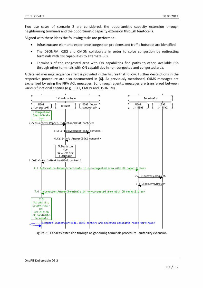
ICT EU OneFIT 30.06.2012
OneFIT Deliverable D5.2
105/117
Two use cases of scenario 2 are considered, the opportunistic capacity extension through neighbouring terminals and the opportunistic capacity extension through femtocells.
Aligned with these ideas the following tasks are performed:
Infrastructure elements experience congestion problems and traffic hotspots are identified.
The DSONPM, CSCI and CMON collaborate in order to solve congestion by redirecting terminals with ON capabilities to alternate BSs.
Terminals of the congested area with ON capabilities find paths to other, available BSs through other terminals with ON capabilities in non-congested and congested area.
A detailed message sequence chart is provided in the figures that follow. Further descriptions in the respective procedure are also documented in [6]. As previously mentioned, C4MS messages are exchanged by using the FIPA ACL messages. So, through agents, messages are transferred between various functional entities (e.g., CSCI, CMON and DSONPM).
Figure 75: Capacity extension through neighbouring terminals procedure –suitability extension.

ICT EU OneFIT 30.06.2012
OneFIT Deliverable D5.2
106/117
Figure 76: Capacity extension through neighbouring terminals procedure – creation.
Also, the implementation of the capacity extension through femtocells is available, which follows the provided procedure:
A macro BS starts experiencing traffic congestion issues. Femtocells are also available in the area;
As soon as the macro BS gets congested, the DSONPM is notified and CSCIs, CMONs collaborate in order to redistribute traffic to uncongested cells in the area;
As a result, traffic is re-assigned to available femtocells and the congestion situation is resolved.
6.3 Implementation of the OneFIT scenario 3 “Infrastructure supported opportunistic ad-hoc networking”
Scenario 3 “Infrastructure supported opportunistic ad-hoc networking” shows the creation of an infrastructure less opportunistic network between two or more devices for the local exchange of information (e.g. peer-to-peer communications, home networking, location-based service providing, etc.). The infrastructure governs the ON creation and benefits from the local traffic offloading, as well as on new opportunities for service providing.
For more information regarding definition of the scenario and description of use cases please refer to D2.1 [3].
OneFIT scenario 3 will be validated using two different approaches. The first one will make use of the validation platform to implement a “local video sharing” use case. The second one will use a specific network emulator where a massive-multi-user service on a high-mobility environment will be deployed.

ICT EU OneFIT 30.06.2012
OneFIT Deliverable D5.2
107/117
6.3.1 Local video sharing implementation
In this use case, 2 or more terminals (smart-phones or laptops) are connected through an ON in order to share a video file via HTTP streaming. One of the terminals is acting as the HTTP server and the other(s) is using the embedded browser to display the video.
The required C4MS is implemented in order to allow the remote establishment of an 802.11 WLAN between the 2 terminals: message exchange is performed using the JADE framework and a limited set of C4MS messages.
This scenario is implemented in the Direct D2D communication test-bed described in section 2.6. The algorithm defined in section 3.3.3.6 UE-to-UE trusted direct path is used to establish the D2D link between the devices. The MSC of the implemented use case including the used C4MS messages is shown in Figure 77.
6.3.2 Opportunistic Service Provision Demonstrator
This demonstration (carried out over the platform described in section 2.3) fits into the scope of OneFIT Scenario 3, especially under use case 3 (“ONs as platforms for location-specific services”), in which the infrastructure manages the creation of ad-hoc opportunistic networks able to support a geographically- and temporally-limited application.
Therefore, to test the usefulness of having an underlying ON-enabled infrastructure network, an example service has been developed. For demonstration purposes, the suggested service is related to the environmental management of ‘Smart Cities’. The ‘Smart City’ concept was developed in [9], and describes economically and environmentally sustainable towns fuelled by modern telecommunications infrastructures. Therefore, power and spectrally efficient wireless network deployments, such as the OneFIT solution, are expected to boost the competitiveness of Smart Cities. Moreover, applications that are opportunistic in nature (e.g. traffic-lights pre-emptive control for emergency/safety vehicles; ad-hoc real-time route retracing for refuse collection; or personalized assistance for tourists) will probably be the common practice when offering services to citizens.
The Smart City-oriented service that has been developed for the demonstration is a tool for the environmental department of a city council to monitor the air pollution emissions of motor vehicles. Such tool might, ultimately, allow them to develop mid-term solutions and policies to enlarge the green footprint of the city. This service takes advantage of the versatility of the OneFIT mechanisms to enable vehicle-to-vehicle and vehicle-to-infrastructure communication links, and to allocate spectrum and other radio resources. The test-bed assumes that most of the vehicles in the monitored city have pollution sensors that collect data about their own emissions (for example, using the OBD-II standard [12], mandatory in all European motor vehicles since more than a decade ago). Vehicles are also assumed to be able to establish wireless connections using any of the available mobile technologies. On the other hand, some infrastructure nodes are deployed at strategic locations where traffic jams usually occur.
The simulated scenario is the following: at certain times of the day, or when vehicle density grows over a threshold, an opportunistic network is created among one of the infrastructure nodes and the surrounding vehicles. The creation of the ON relies on the awareness of the radio context and the cognitive mechanisms to allocate resources in both infrastructure nodes and terminals. Once the ON is established, all the vehicles begin downloading their emissions logs, relaying through other vehicles when needed and using the infrastructure node as a gateway to reach the city council monitoring server. The server collects all these logs and stores them for further analysis. During the process, vehicles keep exiting and entering the monitored area, but the ON will be kept alive through different users. After the traffic jam situation ends or the rush hour expires, the ON is dissolved.
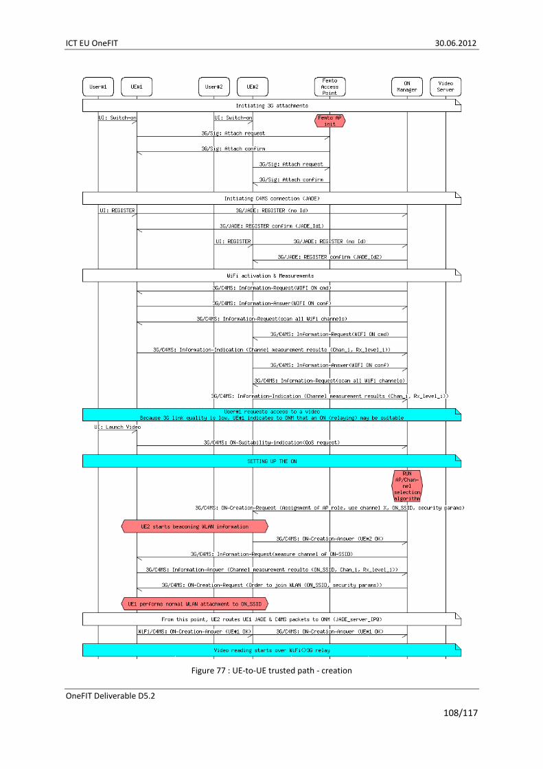
ICT EU OneFIT 30.06.2012
OneFIT Deliverable D5.2
108/117
Figure 77 : UE-to-UE trusted path - creation
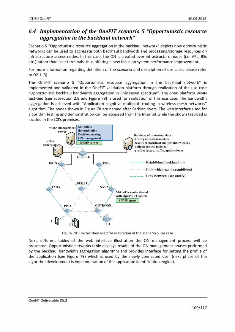
ICT EU OneFIT 30.06.2012
OneFIT Deliverable D5.2
109/117
6.4 Implementation of the OneFIT scenario 5 “Opportunistic resource aggregation in the backhaul network”
Scenario 5 “Opportunistic resource aggregation in the backhaul network” depicts how opportunistic networks can be used to aggregate both backhaul bandwidth and processing/storage resources on infrastructure access nodes. In this case, the ON is created over infrastructure nodes (i.e. APs, BSs etc.) rather than user terminals, thus offering a new focus on system performance improvement.
For more information regarding definition of the scenario and description of use cases please refer to D2.1 [3].
The OneFIT scenario 5 “Opportunistic resource aggregation in the backhaul network” is implemented and validated in the OneFIT validation platform through realization of the use case “Opportunistic backhaul bandwidth aggregation in unlicensed spectrum”. The open platform WMN test-bed (see subsection 2.9 and Figure 78) is used for realization of this use case. The bandwidth aggregation is achieved with “Application cognitive multipath routing in wireless mesh networks” algorithm. The nodes shown in Figure 78 are named after Serbian rivers. The web interface used for algorithm testing and demonstration can be accessed from the Internet while the shown test-bed is located in the LCI’s premises.
Figure 78: The test-bed used for realization of the scenario 5 use case
Next, different tables of the web interface illustration the ON management process will be presented. Opportunistic networks table displays results of the ON management phases performed by the backhaul bandwidth aggregation algorithm and provides interface for setting the profile of the application (see Figure 79) which is used by the newly connected user (next phase of the algorithm development is implementation of the application identification engine).

ICT EU OneFIT 30.06.2012
OneFIT Deliverable D5.2
110/117
Figure 79: Opportunistic networks table – settings phase
In the initial state of the demonstration there are no clients connected to the APs which are considered as candidates (OUTDOOR and PIVA) for ON creation in order to enable multipath routing between them and the existing GWs. Figure 80 shows what happens when a new user connects to the OUTDOOR AP and requests the VoIP service. Opportunistic networks table will display algorithms query for suitable opportunistic network (multiple paths set). It includes name of the node for which the multipath needs to be enabled, time of the query, required bandwidth and ETX (expected transmission count) of the detected application profile, available bandwidth and ETX on the current paths connecting the OUTDOOR AP with the TISA GW. We can see which of the two QoS requirements triggered the algorithm, insufficient bandwidth or, in this case, higher ETX.
Figure 80: Opportunistic networks table - start of the suitability phase
Once the algorithm finds suitable path it starts the ON Creation phase (see Figure 81). In the Opportunistic table the selected additional path (BEGEJ - TISA) and its available bandwidth and ETX as well as total available bandwidth, provided by combination of selected path with the current one, are displayed. In this phase, algorithm will send configuration commands to nodes in order to create additional path for the OUTDOOR AP.
Figure 81: Opportunistic networks table – creation phase
After reconfiguration of the underlying WMN, the algorithm waits for confirmation of the process. If the ON is successfully created, confirmation can be found in the contextual database which is updated by the monitoring system. The corresponding 802.11a interfaces of the OUTDOOR AP are now active which is detected by their UP status in the Interfaces table stored in the contextual database and which is also presented in the web interface (see Figure 82).
OLSR Links table will also display that there is a link between OUTDOOR and BEGEJ and the new path from the OUTDOOR to the TISA GW (see Figure 83).
After verifying that necessary connection was made (ON created), algorithm will enter the ON Maintaining phase (see Figure 84) and it will continuously check if the ON is still required.

ICT EU OneFIT 30.06.2012
OneFIT Deliverable D5.2
111/117
Figure 82: Interface table – showing that corresponding 802.11a interfaces of the OUTDOOR are UP
Figure 83: OLSR table – a new entry for the new path between OUTDOOR and TISA GW over the BEGEJ AP
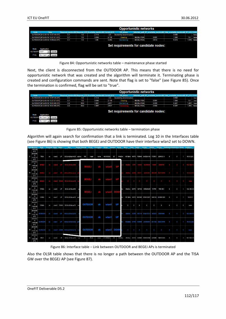
ICT EU OneFIT 30.06.2012
OneFIT Deliverable D5.2
112/117
Figure 84: Opportunistic networks table – maintenance phase started
Next, the client is disconnected from the OUTDOOR AP. This means that there is no need for opportunistic network that was created and the algorithm will terminate it. Terminating phase is created and configuration commands are sent. Note that flag is set to "false" (see Figure 85). Once the termination is confirmed, flag will be set to "true".
Figure 85: Opportunistic networks table – termination phase
Algorithm will again search for confirmation that a link is terminated. Log 10 in the Interfaces table (see Figure 86) is showing that both BEGEJ and OUTDOOR have their interface wlan2 set to DOWN.
Figure 86: Interface table – Link between OUTDOOR and BEGEJ APs is terminated
Also the OLSR table shows that there is no longer a path between the OUTDOOR AP and the TISA GW over the BEGEJ AP (see Figure 87).
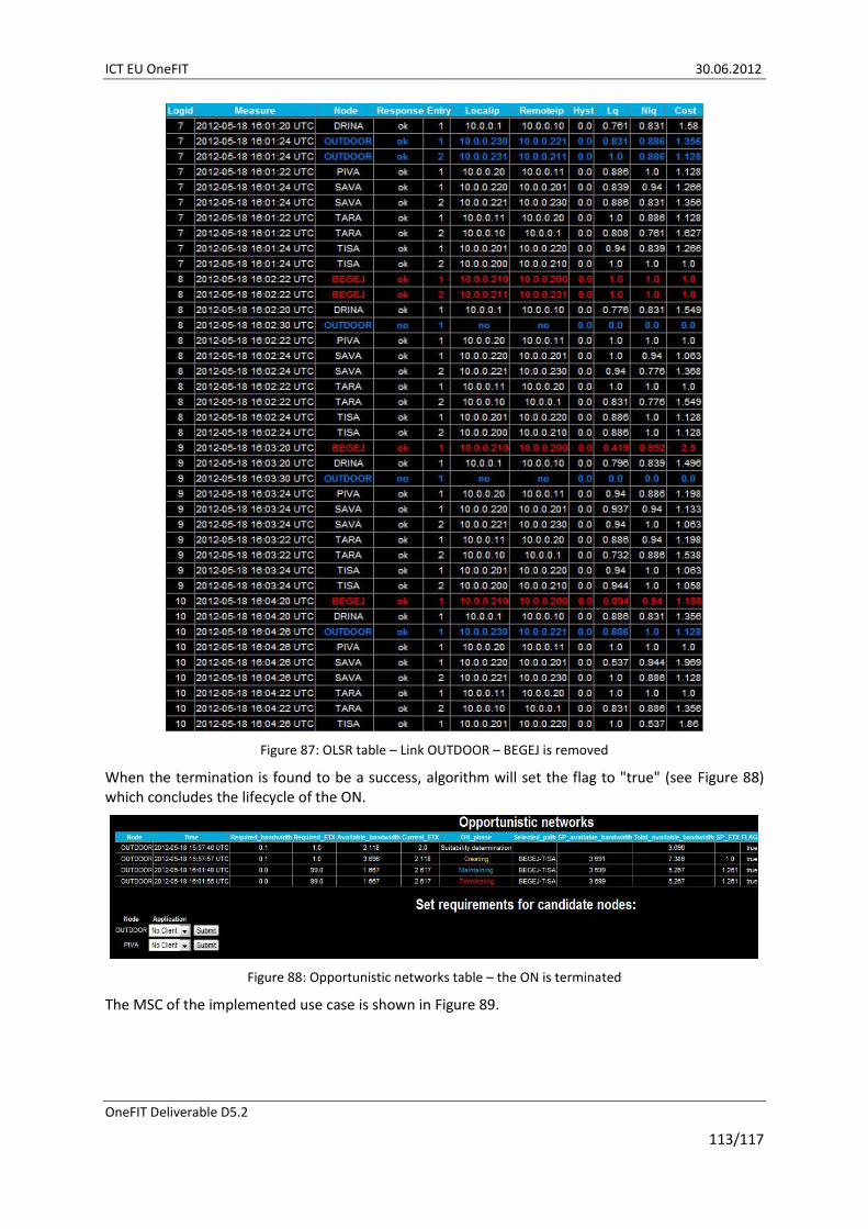
ICT EU OneFIT 30.06.2012
OneFIT Deliverable D5.2
113/117
Figure 87: OLSR table – Link OUTDOOR – BEGEJ is removed
When the termination is found to be a success, algorithm will set the flag to "true" (see Figure 88) which concludes the lifecycle of the ON.
Figure 88: Opportunistic networks table – the ON is terminated
The MSC of the implemented use case is shown in Figure 89.

ICT EU OneFIT 30.06.2012
OneFIT Deliverable D5.2
114/117
Figure 89: MSC of the backhaul bandwidth aggregation in WMN

ICT EU OneFIT 30.06.2012
OneFIT Deliverable D5.2
115/117
7 Conclusion For the verification of the OneFIT scenarios, architecture, algorithms and protocols, several test-beds have been developed for the OneFIT validation platform. Detailed description of these test-beds and their role in the OneFIT validation platform is provided in this document. These test-beds are used to verify the main OneFIT scenarios, which provide:
Opportunistic coverage extension;
Opportunistic capacity extension;
Infrastructure supported ad-hoc networking and device-to-device communication;
Opportunistic resource aggregation in the backhaul network.
All of the involved partners’ test-beds are described and clearly mapped onto the ON related challenges, ON management phases, OneFIT algorithms, scenarios and onto the overall OneFIT validation platform. Joint capabilities of these test-beds are sufficient and are successfully addressed by the majority of the OneFIT system requirements (defined in D2.1 [3] and D2.2 [4]). However, limited requirements related mostly to security aspects (such as protection of user/device identity, or secured protocol communication) remain out of the main focus of the OneFIT project and are not fully addressed so far. For fulfilment of these requirements, available standard solutions can be used. The main requirements, with respect to OneFIT project tasks, are successfully addressed within implementation of partners’ test-beds.
The implementation of the OneFIT building blocks is described in three sections. All of the OneFIT building blocks are successfully implemented into the OneFIT validation platform and corresponding partners’ test-beds. First, the implementation of the ON cognitive management systems (CMON and CSCI) is described together with the description of the realization of the ON management phases. Next, a description of the implementation of the OneFIT supporting blocks (JRRM, CCM, DSM and DSONPM) is given. Finally, a description of how the C4MS protocol is implemented into the OneFIT validation platform is provided. With the implementation of the C4MS protocol, measurements have been made on how much signalling is needed for the management of opportunistic networks. These results have been incorporated into the C4MS signalling evaluation and performance assessment described in D3.3 [7]. Implemented variants of the C4MS protocol (802.21MIH and SNMP/OLSR) and the OneFIT supporting building blocks provide solid basis for implementation of the OneFIT algorithms for enabling ONs. A list of the OneFIT algorithms (enabling cognitive management systems and OneFIT supporting blocks) and C4MS variants which are implemented into the OneFIT validation platform is provided. Implemented algorithmic solutions provide all of the functionalities required for CMON and CSCI cognitive management systems realization. Although there are different algorithmic solutions providing the same functionality (i.e. routing), these solutions address different situations and are applicable in different contextual environments/scenarios (i.e. Application cognitive multipath routing is applicable between infrastructure nodes while Multi flow routes co-determination algorithm is applicable in ad-hoc networks between mobile terminals).
The last section of the document provides a description of the implementation of different OneFIT scenarios into the validation platform (test-beds comprising it). Implemented scenarios include enough aspects of the OneFIT system solution for enabling its successful validation.
Next steps in WP5 are related to the further exploitation of the available test-bed platforms: Following the project planning, at the time that this document is finalized, the development cycle has ended and the phase of results analysis and validation has started. The forthcoming WP5 deliverable D5.3 will therefore contain corresponding results on operational characteristics and performance measurements indicating the benefits of the proposed solutions and implementation approaches.

ICT EU OneFIT 30.06.2012
OneFIT Deliverable D5.2
116/117
8 References [1] ICT-2009-257385 OneFIT Project, http://www.ict-onefit.eu/
[2] OneFIT Deliverable D5.1 “Validation platform specification”, September 2011.
[3] OneFIT Deliverable D2.1 “Business scenarios, technical challenges and system requirements”, October 2010.
[4] OneFIT Deliverable D2.2 “OneFIT functional and system architecture”, February 2011.
[5] OneFIT Deliverable D3.1 “Proposal of C4MS and inherent technical challenges”, March 2011.
[6] OneFIT Deliverable D3.2 “Information definition and signalling flows”, September 2011.
[7] OneFIT Deliverable D3.3 “Protocols, performance assessment and consolidation on interfaces for standardization”, June 2012.
[8] OneFIT Deliverable D4.1 “Formulation, implementation considerations, and first performance evaluation of algorithmic solutions”, May 2011.
[9] OneFIT Deliverable D4.2 ”Performance assessment & synergic operation of algorithmic solutions enabling opportunistic networks”, June 2012.
[10] ETSI TR 102684 “Feasibility Study on Control Channels for Cognitive Radio Systems”, April 2012.
[11] Caragliu, A. & Del Bo, C. & Nijkamp, P. “Smart cities in Europe” Serie Research Memoranda 0048, VU University Amsterdam, Faculty of Economics, Business Administration and Econometrics, 2009.
[12] OBD II Standard, http://standards.sae.org/j1978_200204/
[13] SUMO: Simulation of Urban Mobility, http://sumo.sourceforge.net/
[14] IEEE Std 802.21-2008, IEEE Standard for Local and Metropolitan Area Networks Part 21: Media Independent Handover Services, IEEE, January 2009.
[15] F. Bouali, O. Sallent, J. Pérez-Romero, R. Agustí “Exploiting Knowledge Management for Supporting Spectrum Selection in Cognitive Radio Networks”, Accepted at CROWNCOM 2012 conference, Stockholm, June, 2012.
[16] Java Agent DEvelopment Platform (JADE), Web site: http://jade.tilab.com
[17] Keränen A., Ott J., Teemu K., “The ONE Simulator for DTN Protocol Evaluation” in Proc. SIMUTools'09: 2nd International Conference on Simulation Tools and Techniques, 2009.
[18] FIPA Abstract Architecture Specification. Foundation for Intelligent Physical Agents, 2000. http://www.fipa.org/specs/fipa00001/
[19] K. Tsagkaris, G. Dimitrakopoulos, A. Saatsakis, P. Demestichas, “Distributed radio access technology selection for adaptive networks in high-speed, B3G infrastructures”, International Journal of Communications Systems, Wiley, Vol. 20, Issue 8, pp. 969-992, August 2007.
[20] D.S.J.D. Couto, et al., “A high-throughput path metric for multi-hop wireless routing,” Wireless Networks, vol. 11, no. 4, 2005, pp. 419-434.
[21] WARP: Wireless Open Access Research Platform, http://warp.rice.edu/trac

ICT EU OneFIT 30.06.2012
OneFIT Deliverable D5.2
117/117
[22] IETF RFC 3262 Optimized Link State Routing Protocol (OLSR), October 2003.
[23] OLSRd: an adhoc wireless mesh routing deamon, http://www.olsr.org/
[24] Universal Software Radio Peripheral (USRP), http://www.ettus.com/