Embed Size (px)
Citation preview

ICT EU OneFIT 30.09.2011
OneFIT Deliverable D5.1
1/70
Validation platform specification– D5.1
Project Number: ICT-2009-257385
Project Title: Opportunistic networks and Cognitive Management Systems for Efficient Application Provision in the Future
Internet - OneFIT Document Type: Deliverable
Contractual Date of Delivery: 30.09.2011
Actual Date of Delivery: 30.09.2011
Editors: M. Mueck
Participants: Please see contributors’ list
Workpackage: WP5
Estimated Person Months: 44.95
Nature: PU
Version: 0.11
Total Number of Pages: 70
File: OneFIT_D5.1_20110930.doc
Abstract The present deliverable introduces the OneFIT Proof-of-Concept (PoC) Architecture which will be used as a basis for the validation platform development throughout the project. This PoC Architecture proposal is validated by identifying the roles of the various components in the framework of the OneFIT Scenarios as derived and detailed in WP2. The applied methodology ensures that all required features are appropriately considered. Furthermore, the hardware components available to the project are detailed which are the basis for the development of an integrated validation platform. Their role is highlighted by an instantiation step which maps the PoC Architecture components to the identified hardware components. Finally, a scenario instantiation is derived which illustrates the role of the various hardware components for the validation of selected OneFIT scenarios.
Keywords List Validation Platform, Proof-of-Concept Architecture

ICT EU OneFIT 30.09.2011
OneFIT Deliverable D5.1
2/70
Executive Summary
The objective of the present document is to
1. Introduce a generic Proof-of-Concept (PoC) Architecture to be used throughout the validation activities of OneFIT;
2. Validate the PoC Architecture by identifying the roles of the various PoC Architecture components in the framework of all OneFIT Scenarios as derived by [3];
3. Outline key hardware components that are available to the project for validation activities;
4. Instantiate the PoC Architecture components by identifying the suitable hardware components that will be used in order to validate inherent functionalities and features;
5. Instantiate selected OneFIT scenarios such that the assembly of hardware components is clarified for each case.
The PoC Architecture derived in the framework of this document is considered to be a key milestone of the OneFIT validation activities. It will serve as a guideline for all further implementation activities as well as a reference to identify the functionalities and features that will be fed from other technical Working Packages of OneFIT into the validation work.
The instantiation of the PoC Architecture illustrates the roles of available hardware components and thus prepares the set-up of an integrated validation platform. This task is finally achieved for the following selected sub-set of OnFIT scenarios:
• Scenario 1 “Opportunistic coverage extension”: A device cannot connect to the network operator’s infrastructure, due to lack of coverage or a mismatch in the radio access technologies;
• Scenario 2 “Opportunistic capacity extension”: A device cannot access the operator infrastructure due to the congestion of the available resources at the serving access node;
• Scenario 3 “Infrastructure supported opportunistic ad-hoc networking”: Involves closely located devices which have common application interests;
• Scenario 4 “Opportunistic traffic aggregation in the radio access network”: Use of opportunistic networks to aggregate traffic in the radio access network;
• Scenario 5 “Opportunistic resource aggregation in the backhaul network”: Use of opportunistic networks to aggregate backhaul bandwidth on access side.
Scenarios 3 and 4 will be addressed in a later stage of the project.
With the present document, the development of the integrated proof-of-concept is suitably prepared. The required interactions among all partners involved in this activity are ensured by the clear identification of roles of all available hardware components with respect to the PoC Architecture and the selected OneFIT scenarios.
The validation of the PoC Architecture furthermore clarifies required interactions with other Working Packages of the project. Those results will indeed serve as a guideline in order to identify and implement required interactions across the project in order to maximize the exploitation of project results.

ICT EU OneFIT 30.09.2011
OneFIT Deliverable D5.1
3/70
Contributors
First Name Last Name Affiliation Email
Jens Gebert ALUD [email protected]
Christian Lange ALUD [email protected]
Andreas Wich ALUD [email protected]
Andreas Georgakopoulos UPRC [email protected]
Panagiotis Demestichas UPRC [email protected]
Vera Stavroulaki UPRC [email protected]
Kostas Tsagkaris UPRC [email protected]
Dimitrios Karvounas UPRC [email protected]
Lia Tzifa UPRC [email protected]
Maria Akezidou UPRC [email protected]
Marios Logothetis UPRC [email protected]
Evangelos Thomatos UPRC [email protected]
Nikos Koutsouris UPRC [email protected]
Yiouli Kritikou UPRC [email protected]
Aimilia Bantouna UPRC [email protected]
Oscar Moreno TID [email protected]
David Visiedo TID [email protected]
Oscar Martin TID [email protected]
Markus Mueck IMC [email protected]
Christian Drewes IMC [email protected]
Florian Nehring IMC [email protected]
Guenter Moser IMC [email protected]
Christian Mouton NTUK [email protected]
Ramon Ferrús UPC [email protected]
Oriol Sallent UPC [email protected]
Dragan Boskovic LCI [email protected]
Milenko Tosic LCI [email protected]
Ognjen Ikovic LCI [email protected]

ICT EU OneFIT 30.09.2011
OneFIT Deliverable D5.1
4/70
Table of Acronyms
Term Meaning
3GPP 3rd Generation Partnership Project
ANDSF Access Network Discovery and Selection Function
AP Access Point
API Application Programmable Interface
AuC Authentication Center
BS Base Station
C4MS Control Channels for the Cooperation of the Cognitive Management System
CA Certification Authority
CCM Configuration Control Module
CCR Cognitive Control Radio
CMON Cognitive Management system for the Opportunistic Network
CPC Cognitive Pilot Channel
CSCI Cognitive management System for the Coordination of the Infrastructure
DSM Dynamic Spectrum Management
DSONPM Dynamic and Self-Organizing Network Planning and Management
EPC Evolved Packet Core
ETSI European Telecommunications Standards Institute
FA Functional Architecture
GSM Global System for Mobile communications
HLR Home Location Register
JRRM Joint Radio Resource Management
KPI Key Performance Indicator
LTE Long Term Evolution
MAC Medium Access Control
MSC Message Sequence Chart
ON Opportunistic Network
OneFIT Opportunistic networks and Cognitive Management Systems for Efficient Application Provision in the Future InterneT
P2P Peer-to-Peer
PCC Policy and Charging Control
PKI Public Key Infrastructure
PoC Proof-of-Concept
QoS Quality of Service

ICT EU OneFIT 30.09.2011
OneFIT Deliverable D5.1
5/70
RAT Radio Access Technology
RRC Radio Resource Control
RRM Radio Resource Management
RRS Reconfigurable Radio Systems
SA System Architecture
SAP Service Access Point
UE User Equipment
UMTS Universal Mobile Telecommunications System
WLAN Wireless Local Area Network

ICT EU OneFIT 30.09.2011
OneFIT Deliverable D5.1
6/70
Table of Contents
Contributors ..................................................................................................................................................... 3 Table of Acronyms.......................................................................................................................................... 4 1. Introduction ............................................................................................................................................... 10 2. Proof-of-Concept Architecture Derivation ..................................................................................... 12 3. Description of available Hardware and Software ........................................................................ 14 3.1 3G Modem Platform and 2G/3G Tracing Tools .............................................................................................. 14 3.2 Prototyping platform for the management of opportunistic networks ......................................................... 18 3.3 MIH and Diameter-based C4MS ..................................................................................................................... 19 3.4 Dynamic Spectrum Manager (DSM) ............................................................................................................... 20 3.5 Opportunistic ad hoc network management Testbed .................................................................................... 22 3.6 Femto Testbed ................................................................................................................................................ 22 3.7 Opportunistic Access Testbed ........................................................................................................................ 25
3.7.1 Hardware component ......................................................................................................................... 26 3.7.2 Software component .......................................................................................................................... 27 3.7.3 Extended software features: spectrum sensing ................................................................................. 27 3.7.4 Extended software features: ARQ protocol ........................................................................................ 28
3.8 Spectrum Opportunity Detection Testbed ..................................................................................................... 28 3.8.1 WARP Platform ................................................................................................................................... 29 3.8.2 Hardware ............................................................................................................................................ 30 3.8.3 Software .............................................................................................................................................. 35
3.9 Mesh Networking Testbed ............................................................................................................................. 38 4. Proof-of-Concept Components ............................................................................................................ 46 4.1 Proof-of-Concept Architecture ....................................................................................................................... 46 4.2 Instantiation of Proof-of-Concept Architecture.............................................................................................. 47
4.2.1 Mobile Device Instantiation ................................................................................................................ 47 4.2.2 Femto BS Instantiation ........................................................................................................................ 48 4.2.3 Infrastructure Instantiation................................................................................................................. 48 4.2.4 WiFi/Mesh-Network Instantiation ...................................................................................................... 49
4.3 Instantiation of Scenarios ............................................................................................................................... 49 4.3.1 Dynamic Spectrum Management ....................................................................................................... 49 4.3.2 Opportunistic Coverage Extension ...................................................................................................... 50 4.3.3 Opportunistic Capacity Extension, solution of a maximum-flow problem ......................................... 52 4.3.4 Opportunistic Capacity Extension through femtocells ....................................................................... 54 4.3.5 Opportunistic Capacity Extension in a home/indoor environment integrated with 3G modem platform ....................................................................................................................................................... 55 4.3.6 Backhaul Bandwidth Aggregation ....................................................................................................... 57 4.3.7 Multi-path routing in wireless mesh networks ................................................................................... 58 4.3.8 Spectrum Opportunity Identification and Selection ........................................................................... 60 4.3.9 Advantage of ONs in end-user services .............................................................................................. 61 4.3.10 User-to-user direct path ................................................................................................................... 62 4.3.11 ON route selection for network coverage extension in a multi-hop mesh ad-hoc cloud ................. 63 4.3.12 Route co-determination for congestion resolution/throughput optimization ................................. 67
5. Conclusions ................................................................................................................................................ 69 6. References .................................................................................................................................................. 70

ICT EU OneFIT 30.09.2011
OneFIT Deliverable D5.1
7/70
List of Figures Figure 1: Demonstration Activities Overview. ...................................................................................... 10 Figure 2: OneFIT System Architecture. ................................................................................................. 12 Figure 3: OneFIT Proof-of-Concept Architecture. ................................................................................. 13 Figure 4: Proof-of-concept and validation IMC modem board. ............................................................ 15 Figure 5: Schematic view on base-band and RF components of the IMC proof-of-concept and
validation platform. ...................................................................................................................... 15 Figure 6: Overall Smartphone Architecture. ......................................................................................... 17 Figure 7: Modem Card as it will be used for proof-of-concept work within OneFIT. ........................... 17 Figure 8: Indicative screenshot of the prototyping platform's GUI ...................................................... 18 Figure 9: Indicative topology of the prototyping platform’s hardware. ............................................... 19 Figure 10: C4MS Protocol Software supporting MIH and Diameter based encoding. ......................... 20 Figure 11: External interfaces and internal structure of the DSM. ....................................................... 21 Figure 12: The GUI of the DSM. ............................................................................................................ 21 Figure 13 : NEC FAP a) side view b) view from behind ......................................................................... 23 Figure 14 : Example of Femtocell Parameters 1 ................................................................................... 24 Figure 15 : Example of Femtocell Parameters 2 ................................................................................... 25 Figure 16 : Example of Femtocell Parameters 3 .................................................................................. 25 Figure 17: USRP board .......................................................................................................................... 26 Figure 18: Physical layout of the testbed .............................................................................................. 29 Figure 19: Physical layout of a WARP board equipped with (max.) 4 radio daughterboards .............. 31 Figure 20: WARP radio daughterboard (2.4 / 5 GHz; 40 MHz bandwidth) ........................................... 33 Figure 21: WARP radio daughterboard block diagram architecture .................................................... 33 Figure 22: WARP radio daughterboard – clocks. .................................................................................. 33 Figure 23: WARP radio daughterboard – RF. ........................................................................................ 34 Figure 24: Design flows ......................................................................................................................... 35 Figure 25: WARPLab setup .................................................................................................................... 36 Figure 26: WARPLab sysgen core and radio board block diagram ....................................................... 37 Figure 27: LCI open platform wireless mesh access point .................................................................... 38 Figure 28: Mesh networking testbed layout. ........................................................................................ 39 Figure 29: Block diagram of LCI open platform wireless mesh AP ....................................................... 40 Figure 30: RB433AH board view ........................................................................................................... 42 Figure 31: RB433AH layout ................................................................................................................... 42 Figure 32: Mobile Device Instantiation. ................................................................................................ 47 Figure 33: Femto BS Instantiation. ........................................................................................................ 48 Figure 34: Infrastructure Instantiation. ................................................................................................ 48 Figure 35: WiFi/Mesh Network Instantiation. ...................................................................................... 49 Figure 36: Dynamic Spectrum Management – Relationship to PoC Architecture. ............................... 50 Figure 37: PoC Architecture component for addressing basic ON mechanisms: Illustration of
Spectrum Measurement Results................................................................................................... 50 Figure 38: Coverage-Extension by D2D Communication. ..................................................................... 51 Figure 39: Coverage extension – Relationship to PoC Architecture. .................................................... 52 Figure 40: Opportunistic Capacity Extension, Out-Door Environment. ................................................ 53 Figure 41: Capacity extension through maximum-flow – Relationship to PoC Architecture. .............. 53 Figure 42: Traffic Hotspot is identified. ................................................................................................ 54 Figure 43: Control environment for Capacity Extension Scenario. ....................................................... 54 Figure 44: Capacity extension through femtocells – Relationship to PoC Architecture. ...................... 55 Figure 45: Home/Office context, initial configuration. ......................................................................... 55 Figure 46: Home/Office context, new nodes leads to congestion situations. ...................................... 56 Figure 47: Home/Office context, congestion situation is resolved. ..................................................... 56

ICT EU OneFIT 30.09.2011
OneFIT Deliverable D5.1
8/70
Figure 48: Opportunistic Capacity Extension in a home/indoor environment integrated with 3G modem platform – Relationship to PoC Architecture. ................................................................. 57
Figure 49: Backhaul bandwidth aggregation mechanism. .................................................................... 58 Figure 50: Backhaul Bandwidth Aggregation – Relationship to PoC Architecture. .............................. 58 Figure 51: ONs / Resource backhaul, resolution of broken links. ......................................................... 59 Figure 52: Multi-path routing in wireless mesh networks - Relationship with PoC Architecture. ....... 60 Figure 53: Spectrum Opportunity Identification and Selection ............................................................ 60 Figure 54: Spectrum Opportunity Identification and Selection - Relationship to PoC Architecture. ... 61 Figure 55: Monitoring of real-time pollution indicators application. ................................................... 62 Figure 56: Advantage of ONs in end-user services - Relationship with PoC Architecture. ................... 62 Figure 57: User-to-user direct path - Relationship with PoC Architecture. .......................................... 63 Figure 58: ONs / Optimized Routing for Coverage Extension. .............................................................. 64 Figure 59: ON route selection for network coverage extension in a multi-hop mesh ad-hoc cloud. .. 64 Figure 60: A device cannot connect to the network operator’s infrastructure, due to lack of coverage
or a mismatch in the radio access technologies. .......................................................................... 65 Figure 61: A device cannot connect to the network operator’s infrastructure, due to lack of coverage
or a mismatch in the radio access technologies – further details based on a “Relaying” within infrastructure coverage approach. ............................................................................................... 65
Figure 62: A device cannot connect to the network operator’s infrastructure, due to lack of coverage or a mismatch in the radio access technologies – further details based on a “Relaying” within ON coverage approach. ................................................................................................................ 66
Figure 63: ONs / Optimized Routing for Coverage Extension. .............................................................. 67 Figure 64: ONs / Optimized Routing for Coverage Extension. .............................................................. 68 Figure 65: ONs / Optimized Routing for Coverage Extension – a more detailed view. ........................ 68

ICT EU OneFIT 30.09.2011
OneFIT Deliverable D5.1
9/70
List of Tables Table 1 : Specification table .................................................................................................................. 22 Table 2: List of the OneFIT System requirements. ................................................................................ 47

ICT EU OneFIT 30.09.2011
OneFIT Deliverable D5.1
10/70
1. Introduction Figure 1 gives a high-level overview on the scope of proof-of-concept framework. As derived by WP2, the following five key scenarios will be considered from a hardware/software implementation perspective in WP5:
Scenario 1: Opportunistic coverage extension;
Scenario 2: Opportunistic capacity extension;
Scenario 3: Infrastructure supported opportunistic ad-hoc networking;
Scenario 4: Opportunistic traffic aggregation in the radio access network;
Scenario 5: Opportunistic resource aggregation in the backhaul network.
Figure 1: Demonstration Activities Overview.
In order to achieve the upper high-level proof-of-concept objectives, the following steps are executed in order to identify specific steps for each project partner:
A Proof-of-Concept (PoC) Architecture is derived as it is further detailed in Chapter 2 of this document. Please note that all key building blocks identified in WP2 are contained on both the terminal and network side within a respectively modified scope. In particular, those concern the following innovative software components developed by the project:
o CSCI: The Cognitive management System for the Coordination of the Infrastructure (CSCI) is responsible for the detection of situations where an ON is useful including the ON suitability determination;
o CMON: The Cognitive Management system for the Opportunistic Network (CMON) is responsible for the creation, maintenance and termination of a given ON based on the context and policy information provided by the CSCI;
o CCM: The Configuration Control Module (CCM) executes the reconfiguration following indications from DSONPM;

ICT EU OneFIT 30.09.2011
OneFIT Deliverable D5.1
11/70
o JRRM: The Joint Radio Resources Management (JRRM) performs the joint management of the radio resources across different radio access technologies;
o DSM: The Dynamic Spectrum Management (DSM) provides mid- and long-term management (e.g. in the order of hours and days) of the spectrum for the different radio systems;
Following the derivation of the PoC Architecture, a validation step is included. Here, the roles of the PoC Architecture building blocks are detailed for each of the OneFIT Scenarios. This step ensures that all required functionalities are covered by the proposed PoC Architecture.
Preparing the actual implementation, the HW/SW components available to the consortium are summarized and a corresponding instantiation of the PoC Architecture components is given.
Finally, an instantiation of the OneFIT Scenarios is performed by highlighting the combination of HW/SW components provided by the consortium in order to showcase an integrated PoC environment.
With the upper steps being addressed, the Validation Platform Specification is finalized.

ICT EU OneFIT 30.09.2011
OneFIT Deliverable D5.1
12/70
2. Proof-of-Concept Architecture Derivation The actual hardware implementation activities are prepared by the derivation of a Proof-of-Concept (PoC) Architecture. This derivation is building on results obtained in Working Package 2 (Business aspects, requirements and technical challenges, evolution of functional and system architecture), in particular the OneFIT system architecture proposal is exploited as illustrated by Figure 2 [3].
Figure 2: OneFIT System Architecture.
Building the generic OneFIT system architecture, a PoC Architecture is straightforwardly derived by
Identifying key building blocks to be implemented for realizing the OneFIT scenarios as introduced by Working Package 2 [2];
Placing the key building blocks of the generic OneFIT System Architecture into the relevant PoC Architecture components;
Introducing suitable connections for signalling and data exchange.
The result of this exercise is illustrated in Figure 3. The validation of the PoC will be performed in the subsequent chapter; in this context, the role of the various PoC Architecture building blocks will be detailed for each of the OneFIT Scenarios.

ICT EU OneFIT 30.09.2011
OneFIT Deliverable D5.1
13/70
Figure 3: OneFIT Proof-of-Concept Architecture.

ICT EU OneFIT 30.09.2011
OneFIT Deliverable D5.1
14/70
3. Description of available Hardware and Software In the sequel, an overview on the current status of hardware/software implementation activities is given. This analysis contains corrective actions which have been implemented after synchronization discussions with WP2, WP3 and WP4. In particular, the algorithmic and software component development activities of those WPs are taken into account in order to maximize the synergies across the project.
3.1 3G Modem Platform and 2G/3G Tracing Tools The IMC Proof-of-Concept and Validation platform provides access via High Speed USB2. The XMM™6160 platform consists of
X-GOLD™616 HSUPA/HSDPA/EDGE baseband IC
Platform software package comprising software infrastructure and cellular protocol stack
SMARTi™-UE based RF engine
Key modem features include
o 3GPP Release 6
o 2G: SAIC, E-GPRS class 12, GPRS class 12
o WCDMA FDD, 384 kbps UL/DL PS WCDMA, 64 kbps UL/DL CS WCDMA
o HSDPA category 8, HSUPA category 6
o GSM bands 850, 900, 1800, 1900
o 3G bands I, II, V, VIII
Some key parameters of the platform include
o Less than 700mm² PCB area
o Approximately 110 components
o Best in class Talk and Standby Time
o 137mA talk, 1.3mA standby in 3G
A photo picture of the platform as well as a schematic view on base-band and RF components are given below.
ICT EU OneFIT 30.09.2011
OneFIT Deliverable D5.1
15/70
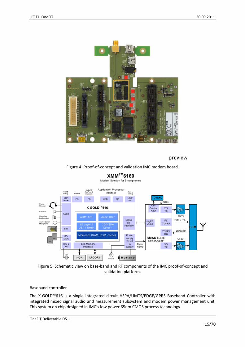
Figure 4: Proof-of-concept and validation IMC modem board.
Figure 5: Schematic view on base-band and RF components of the IMC proof-of-concept and validation platform.
Baseband controller
The X-GOLD™616 is a single integrated circuit HSPA/UMTS/EDGE/GPRS Baseband Controller with integrated mixed signal audio and measurement subsystem and modem power management unit. This system on chip designed in IMC’s low power 65nm CMOS process technology.

ICT EU OneFIT 30.09.2011
OneFIT Deliverable D5.1
16/70
In addition to the modem functionality the X-GOLD™616 provides latest OMTP security standards. Integrated audio codecs and “Class D” amplifiers enable powerful stereo CD quality output to headsets as well as hands-free speakers without additional components.
The processing of the 2G/3G cellular protocol stack layer are handled by an ARM® 1176 Embedded Microcontroller. The physical layer of the cellular protocol stack and the voice processing is handled by dedicated hardware accelerator subsystems.
The wide range of connectivity options include a V3.09 Dig RF interface, parallel as well as high-speed serial MIPI® interfaces, USB® 2.0 HS, multiple SDIO capable MMC/SD card interfaces to flexibly connect to all sorts of PAN, LAN and broadcasting engines, , combined SPI/UART as well as I2C ports, a direct USIM interface, also via inter-chip full speed USB, and I2S’s for digital audio transfer.
Some features:
General: DBB, ABB, PMU, stack
Technology: 65nm
Package: PG-VF2BGA, 8.5x8.5x1.0mm
Pitch: 0.4mm
MCU: ARM11 416 MHz,
Modem GSM: GSM/CSD/E-GPRS class 12, SAIC, TTY, EDGE,
Modem UMTS: WCDMA FDD, 384 kbps UL/DL PS WCDMA, 64 kbps UL/DL CS WCDMA,
Modem HSPA: 7.2 Mbps HSDPA cat. 8, 5.76 Mbps HSUPA cat. 6,
Integrated power management unit,
FR/HR/EFR, NB/WB-AMR speech codecs,
Connectivity and interfaces: LPDDR1, PSRAM, SDRAM, NOR, NAND; 3xUSIF, 1xI2C, 2xI2S; Debug I/F; Direct (U)SIM 1.8/3V; USB2.0 High Speed, SD Card I/F; IPC: SPI, USB, RF engine.
The SMARTi™-UE RF Engine is an RF solution for a 4-band GSM / 4-band UMTS mobile phone product. It includes a GMSK/8-PSK PA + Switch Module, 4 UMTS PA Modules, a quad-band LNA Module, a penta-band Filter Module and a TCVCXO Module.
The heart of the RF Engine is the SMARTi™-UE, a highly integrated UMTS/EDGE-transceiver, with all necessary features to enable multimode, multiband telephone applications. It incorporates a fully integrated dual mode receiver, multi band TX outputs, TCVCXO control, a measurement interface, DigRF V3.09 compliant high speed data and control interface, a multimode timer unit and all necessary front end signals for the complete RF Engine control. Overall this RoHS compliant IC directly supports RF engines with up to 4 GSM bands and typ. 3 UMTS (can be less or more depending on engine setup) bands without additional discrete RF path switches.
Some features:
Package: 6x6x0.8 mm, 0.5 pitch,
GSM/EDGE Quad band transceiver,
HSPA Triple band transceiver,
2G band support: 800,900,1800,1900,
3G band support: Bands I-X w/o VII,
TRP / closed loop power control.

ICT EU OneFIT 30.09.2011
OneFIT Deliverable D5.1
17/70
Platform software
The software for the platform is divided into following groups
Cellular Protocol Stack (CPS) (3GPP dual mode release 6)
o Drivers
o Operating system
o Connectivity Stacks
o Data Protocols
o Security framework
o Universal Terminal API CPS Adapter
o IO Services
o AT command interface
The overall Smartphone Architecture is illustrated below:
VisioDocument
1
#0*
987
654
32
Camera
SMARTiTM
UE
W-LAN
Application
Processor
3G PA
3G PA
FEM
+
2G
PA
Display
Bluetooth
IPC
SPI
Audio
I2S
X-GOLDTM
616
2G DSP / Audio
ARM 1176 @ 416 MHz
Vibrator
Loud
speaker
HSPA subsystem
Power management
3G PAFlash DDR
A-GPS
Flash DDR
AP
PMIC
SIM CardDirect USIM
interface
Battery
MMC/SD Card
DVB-H
Figure 6: Overall Smartphone Architecture.
The card is finally delivered as a PCI-Express Card as illustrated below:
Figure 7: Modem Card as it will be used for proof-of-concept work within OneFIT.

ICT EU OneFIT 30.09.2011
OneFIT Deliverable D5.1
18/70
In addition to the above mentioned hardware, a set of sophisticated tracing tools is provided to project partners. It allow to trace messages exchanged between the mobile devices and the base-stations and will allow for accessing to information such as Signal-to-Interference-Ratios, TX output power levels, RRC messages, etc.
3.2 Prototyping platform for the management of opportunistic networks
The prototyping platform for the management of opportunistic networks comprises cognitive management systems and control channels and aims at the efficient application provision through the management of opportunistic networks in coordination with the infrastructure. It has been developed as a Multi Agent System (MAS) based on JAVA and JADE [4] and it consists of several software and hardware components that can support the execution of a great variety of scenarios and use cases and moreover they are facilitating the integration of new hardware or software functionalities that are developed in the context of prototyping activities. The prototyping platform is intrinsically flexible and extendable, since it is based on JADE middleware that enables the integration, interaction and cooperation of all the entities that reside in it. The platform offers high-level interfaces with various interconnection ways, enabling experimentation with different problem handling practices, varied hardware and software configurations or even diverse architecture designs.
Software includes agents that run on terminals and are able to communicate and manage devices like the 3G modem provided by IMC, agents that are used to generate traffic and simulate network conditions for demonstration and validation purposes, agents that are responsible for interfacing with software or hardware components like the DSM provided by ALU or the Femtocells provided by NTUK. An indicative screenshot of the platform’s main GUI is shown in Figure 8.
Figure 8: Indicative screenshot of the prototyping platform's GUI
Hardware includes the following network elements and devices that are also depicted in Figure 9 showing an indicative topology of the prototyping platform: 2 CISCO Catalyst 3750 Core switches, 5

ICT EU OneFIT 30.09.2011
OneFIT Deliverable D5.1
19/70
CISCO Catalyst 3560 Access switches, 2 HP ML350T05 servers, 2 CISCO 2811 VoIP gateways, 1 Network Management System running the HP NNM (Network Node Manager), 5 CISCO ASA 5505 Firewalls, 5 CISCO AIR-AP1131AG WLAN Access Points, 2 CISCO AIR-AP1242G WLAN bridges, 2 PROXIM Tsunami WiMAX base stations, 2 PROXIM Tsunami WiMAX subscriber units, 23 HP Compaq dc7900 PCs, 10 HP EliteBook 6930p Laptops, 5 HP IPAQ DATA MESSENGER PDAs with GPS, 3G, EDGE, GPRS, WLAN and Bluetooth support, 2 Nokia n810 Tablet PCs with WLAN, Bluetooth and GPS support, 1 Huawei 3G modem with GPRS, EDGE, UMTS and HSPA support.
Figure 9: Indicative topology of the prototyping platform’s hardware.
3.3 MIH and Diameter-based C4MS The C4MS protocol stack is a software package to send and receive C4MS messages via TCP/IP. Dependent on the configuration, the messages are encoded in an IEEE 802.21 MIH [7] compatible format or are encoded using extensions of the IETF Diameter base protocol [6]. Further information on these protocol options can be found in D3.1 [5].
The principal layout of the C4MS Software package is shown in Figure 10. Any node in the network can act as C4MS-Client, as C4MS-Server or as both at the same time. A C4MS-Client is sending requests and processing responses while a C4MS-Server waits for requests and answers them.
A client must first create a C4MSMessage by calling the create-procedure of the C4MSMessageFactory. Then parameters can be added to the C4MSMessage by using set-procedures. Then, the C4MSClientStack is called to send the message. When an answer is received, the user of the C4MS stack is called to process the answer message.
On Server side, upon reception of a request, the user of the C4MS request can retrieve parameters of the C4MSMessage by using get-procedures. For creating an answer-message, the C4MSMessageFactory is used. The answer is then sent via the C4MSServerStack.

ICT EU OneFIT 30.09.2011
OneFIT Deliverable D5.1
20/70
C4MS
Software
Package
Class sending C4MS
requests and receiving
answers
Class receiving C4MS
requests and sending
answers
C4MSMessageFactory
DiameterMessageImplMIHMessageImpl
C4MSClientStack C4MSServerStack
C4MSMessage
interface
C4MSUser
interface
C4MSUser
interface
TCP/IP Stack TCP/IP Stack
Cre
ate
Msg
Cre
ate
Msg
get/
se
t pa
ram
ete
rs
get/
se
t pa
ram
ete
rs
pro
ce
ssA
nsw
er
pro
ce
ssR
eq
ue
st
se
nd
Re
qu
est
se
nd
An
sw
er
Figure 10: C4MS Protocol Software supporting MIH and Diameter based encoding.
3.4 Dynamic Spectrum Manager (DSM) The Dynamic Spectrum Management (DSM) handles spectrum policies and decides on which spectrum to use for the cells in a radio access network. Further on, the DSM provides guidance on which spectrum to use in an Opportunistic Network.
Figure 11 shows the DSM with its external interfaces and its internal building blocks.
Users of the DSM like e.g. the CSCI or the DSONPM can access the DSM via the CS or the MS interface as specified in the OneFIT Functional Architecture [3]. This spectrum related information can be used for the suitability determination of ONs as well as for the decision making on which spectrum shall be used in an ON.
The SS Interface is used to retrieve information from an external TV-white space geolocation database or to exchange information with other DSM instances.
Due to the usage of the MIH and Diameter-based C4MS as described in section 3.3 before, both IETF Diameter [6] and IEEE 802.21 MIH [7] based message encoding is currently supported by the DSM for the CS/MS/SS Interface.

ICT EU OneFIT 30.09.2011
OneFIT Deliverable D5.1
21/70
DSM Users
DSM
DSONPM
CS
Operator’s
Infrastructure
Country-wide spectrum database
Geo-location database
SS
MS
CSCI CMON
Protocol Stack
Protocol Stack O&M
Interface
(GUI)
Policies for
shared accessCurrent
Spectrum
Usage
Spectrum
Management
Policies for
exclusive access
Primary white
Space users
DSM Users
DSM
DSONPM
CS
Operator’s
Infrastructure
Country-wide spectrum database
Geo-location database
SS
MS
CSCI CMONCSCI CMON
Protocol Stack
Protocol Stack O&M
Interface
(GUI)
Policies for
shared accessCurrent
Spectrum
Usage
Spectrum
Management
Policies for
exclusive access
Primary white
Space users
Figure 11: External interfaces and internal structure of the DSM.
Internally, the DSM stories policies including the regulatory framework for shared access as well as for exclusive spectrum access.
The network (e.g. the networks DSONPM) informs the DSM on already existing cells in the network. This is typically done with a “Register-Cell-Request” (RCR) message.
Further on, in the case a new cell is setup or an existing cell is being reconfigured, the DSM provides information on which frequency to configure for the new/modified cell. In such a case, the client can send a “Spectrum-Assignment-Request” (SAR) to the DSM indicating the capabilities of the transceiver like e.g. supported frequency ranges and bandwidth. The DSM executes the Spectrum Assignment procedures and replies with a “Spectrum-Assignment-Answer” (SAA) message providing information on which spectrum to use.
The DSM also provides a GUI to display policies, current spectrum usage and a geographical view on cell location. Figure 12 shows the GUI of the DSM where primary TV-band users are shown in red, licensed spectrum assignments are shown in green and the ISM-bands are shown in blue. The frequencies of registered cells are shown in brown or dark green colour.
Figure 12: The GUI of the DSM.

ICT EU OneFIT 30.09.2011
OneFIT Deliverable D5.1
22/70
3.5 Opportunistic ad hoc network management Testbed The opportunistic ad-hoc network management is composed of 2 software packages, which are implemented into the terminals. The first software package is an implementation of part of the CSCI layer; it processed the multi-hop routes discovery and identification. It is related to the function “ON suitability and determination to reach gateway nodes (i.e. node connected to infrastructure)” function identified in the functional architecture (D2.2). The second software package is a part of the CMON layer. It processes the multi-hop route selection. It is related to the “ON creation and maintenance”.
These software packages would be interfaced to the C4MS protocol layer to allow the exchange of necessary information between the terminals (for example it is possible to integrate these software packages to the module described in the section 3.3). They are also interfaced with the IP protocol layer to control the radio path selection. The software packages are interfaced with the RATs, in order to retrieve the radio metric calculated by these RATs.
The first prototype will be basically developed and validated under the WARP environment (see WARP platform description in section 3.8.1), as a module located in the HOST PC connected to the WARP radios.
3.6 Femto Testbed
The NEC Femto Access Point (FAP) is a ‘zero touch’ plug-and-play consumer device made by Ubiquisys which is installed at the subscriber premises and connects to the operator’s core network over the subscriber’s broadband connection by using an Ethernet connection. The FAP provides localised 3G coverage and dedicated capacity in a home enhancing the end user experience through improved Quality of Service (QoS). We can find below a table for the main specifications of the NEC FAP:
Standards 3GPP Release 5 2005-06
Range 200 m maximum
Voice Channel Up to four users
Data Channels 64 kbps bi-directional (four users)
128 kbps downlink and 64 kbps uplink (four users)
324 kbps downlink and 128 kbps uplink (two users)
384 kbps downlink and 324 kbps uplink (one user)
HSDPA support User Equipment categories 1-8, 11 and 12
Peak HSDPA rate 3.6 Mbps
Frequency bands Receive : 1920 MHz to 1980 MHz Transmit : 2110 MHz to 2170 MHz
Transmit Power 10 dBm maximum
Ethernet Interface 10/100 RJ-45 Ethernet port
Number of antennas 1 (internal)
Power +6V DC at 2.5A maximum
Table 1 : Specification table

ICT EU OneFIT 30.09.2011
OneFIT Deliverable D5.1
23/70
Figure 13 : NEC FAP a) side view b) view from behind
The FAP interworks with the legacy 3G handsets using the 3rd Generation Partnership Project (3GPP) Uu interface. The FAP connects over the broadband to the RAN GW using the 3GPP standard Up interface as described below:
It has a (U)SIM dedicated to the access point provisioning, configuration, authentication with the core network and to support UMTS services for the home number service.
It provides local UMTS coverage at 3GPP standards.
It interfaces with multiple Universal Equipment (UEs) over the 3GPP standard Uu interfaces, terminating locally Access Stratum (AS) and Non Access Stratum (NAS) layers. The UEs are 3GPP standard UMTS UEs and require no additional client. There is no restriction on the type of terminal used - they can be handsets, Personal Digital Assistants (PDAs), Personal Computer (PC) cards or any other form factor.
It supports terminal adaptation and is capable of allowing home number calls to be made using Plain Old Telephone Service (POTS) or Session Initiation Protocol (SIP) phones.
The PC client allows the end user to control local services preferences, contacts and dynamic calls/sessions behaviour. Softphone functionality can be included in the PC client and used to make outgoing home number calls.
The following are types of configuration settings that could be configured via the Graphic User Interface (GUI):
Baseline Service Configuration:
Mobile Country Code (MCC) and Mobile Network Code (MNC)
IP Security (IP Sec)
UMA or IMS settings
Homezone Name
Operations and Maintenance (O&M) baseline configuration

ICT EU OneFIT 30.09.2011
OneFIT Deliverable D5.1
24/70
Customer/Subscription Service Configuration (i.e. per customer settings)
Address, Post Code
Public Land Mobile Network (PLMN) Cell Identity (ID)
Neighbour Cell List
Access (subscriber Universal Equipment (UEs)) List
Figure 14 : Example of Femtocell Parameters 1
Dynamic Service Configuration:
Radio Frequency (RF) Profile (e.g. allowed frequencies, allowed scrambling codes, Location Area Code (LAC) ranges)

ICT EU OneFIT 30.09.2011
OneFIT Deliverable D5.1
25/70
Figure 15 : Example of Femtocell Parameters 2
Power configuration
Figure 16 : Example of Femtocell Parameters 3
3.7 Opportunistic Access Testbed Spectrum opportunity identification and selection are key technical challenges involved in different stages of an opportunistic network. Therefore, the implementation of certain spectrum opportunity identification capabilities will constitute a building block that will provide potential into the overall

ICT EU OneFIT 30.09.2011
OneFIT Deliverable D5.1
26/70
OneFIT demonstration framework. Based on the identified spectrum opportunities, a certain spectrum will be selected in order to conduct a communication between a pair of nodes forming an opportunistic network.
Spectrum opportunity identification can be envisaged at very different time/frequency/space scales, this having a strong impact on the hardware & software requirements. For example, for large and stationary large temporal scale over a wide range of frequency bands a spectrum analyser may be required (e.g. an Anritsu MS2721B is available for the purpose of OneFIT demonstrations, which can be the base for the generation of a spectrum occupancy database). In turn, identification of spectrum opportunities at shorter time scales in specific frequency bands such as ISM can be efficiently performed on USRP board platform. This equipment, which is also able to transmit and receive over the ISM band, is brought to the OneFIT demonstration framework. Its main characteristics are described in the following, together with some software modules that have been specifically developed to address some of the expected requirements that will be needed for the development and demonstration of spectrum opportunity identification and selection capabilities in OneFIT.
3.7.1 Hardware component
The USRP is an integrated board which incorporates AD/DA Converters (ADCs/DACs), some forms of Radio Frequency (RF) front end, and a Field Programmable Gate Array (FPGA) which does some important but computationally expensive pre-processing of the input signal [8]. A typical setup of the USRP board consists of one mother board and up to four daughter boards, as shown in Figure 17: USRP board.
Figure 17: USRP board
On the mother board there are four slots, where up to 2 RX and 2 TX daughter boards can be plugged in. The daughter boards are used to hold the radio frequency receiver and the radio frequency transmitter. As illustrated in the figure, there are precisely 4 high-speed 12-bit ADCs and 4 high-speed 14-bit DACs. All the ADCs and DACs are connected to the FPGA; it performs high bandwidth math, such as interpolation and decimation, to reduce the data rates to something that can be transmitted to a processor over a USB 2.0 controller. The DACs clock frequency is 128 Ms/s, so Nyquist frequency is 64 MHz. While, ADCs work at 64 Ms/s to digitize the received signal and the FPGA performs filtering and digital down-conversion (decimation). Decimation factor is required in order to adapt the incoming data rate to the USB 2.0 and PC computing capabilities. A USB controller

ICT EU OneFIT 30.09.2011
OneFIT Deliverable D5.1
27/70
sends the digital signal samples to the PC in 16-bit I and 16-bit Q complex data format (4 bytes per complex sample), resulting in a maximum rate of 8 Ms/s. The maximum RF bandwidth that can be handled is therefore 8 MHz (narrower bandwidths can be selected by adjusting the decimation rate).
There exist different kinds of daughter boards that allow a very high USRP reconfigurability; in fact, such boards can work at several frequency bands. In particular, the daughter boards integrated in the considered USRP motherboard are XCVR2450 Transceivers. The frequency ranges they work in are: 2.4 - 2.5 GHz and 4.9 - 5.9 GHz. The first range consists specifically of the 13 sub-bands around the 2.4 GHz ISM band (2.412 GHz to 2.472 GHz in 5 MHz steps); such a band is reserved for WiFi applications (i.e. IEEE 802.11b, 802.11g and 802.11n standards).
3.7.2 Software component
Identification of spectrum opportunities is performed by both a hardware platform (i.e. USRP) and a software component. GNU Radio is the toolkit considered as the software component. It is a software for learning about, building and deploying software radios [9]. GNU Radio is free and open source, it comes with complete source code so anyone can look and see how the system is built. In particular, GNU Radio provides a library of signal processing blocks and the glue to tie it all together. In GNU Radio, the programmer builds a radio by creating a graph (as in graph theory) where the vertices are signal processing blocks and the edges represent the data flow between them.
All the signal processing blocks are written in C++ and Python is used to create a network or graphs and glue these blocks together. Therefore, in this particular scenario Python is a higher level language. Many useful and frequently used blocks have been provided by the GNU Radio project (i.e. about 100 blocks); hence, in many cases is not needed to use C++, only utilizing Python could be enough. However, to do more sophisticated works, C++ can be used to develop personal blocks.
There is also a graphical environment available to create a custom radio; this is called GNU radio Companion (GRC). It is a graphical user interface which allows GNU Radio components to be put together graphically. Simplified Wrapper and Interface Generator (SWIG) is an open source package used by GNU Radio as glue such that the C++ classes can be used from Python. SWIG has the ability to convert the C++ classes into Python compatible classes. As a result, the whole GNU Radio framework is capable of putting together and exploiting the benefits of both C++ and Python.
GNU Radio can be installed on different kinds of operating systems, like MS Windows, Apple Mac OS X and Linux. There are different versions of GNU Radio available. The latest stable release is currently version 3.3.
3.7.3 Extended software features: spectrum sensing During the spectrum sensing activity it can be determined which portions of a certain spectrum are available to opportunistic users. The GNU Radio function used for this activity is usrp_spectrum_sense.py, found in gnuradio-examples/python/usrp. Firstly, the original code has been considered to validate that the USRP motherboard can be used to detect the utilization of the bands taken into account (i.e. 2.4 - 2.5 GHz and 4.9 - 5.9 GHz).
Then, such code has been modified to be able to demonstrate how it is possible to obtain the state occupancy of a certain bandwidth starting from a selected Frequency Resolution (FR). Hence, a spectrum sensing experiment has carried out from 2.4 GHz to 2.5 GHz in 100 kHz slots realizing how the total occupied bandwidth is centred in the ISM channels that the WiFi Access Points were using during the experiment. In particular, for every 100 kHz spectrum block the implemented code gives, during the experiment, intervals of consecutives 1s and 0s respectively for occupancy and vacancy periods (1 means that the sensed signal strength is greater than a selected power threshold, while 0 means that the sensed signal strength is smaller than the threshold). The power threshold to decide if a channel is free is set in according to several studies found in literature such as [10] and [11].
ICT EU OneFIT 30.09.2011
OneFIT Deliverable D5.1
28/70
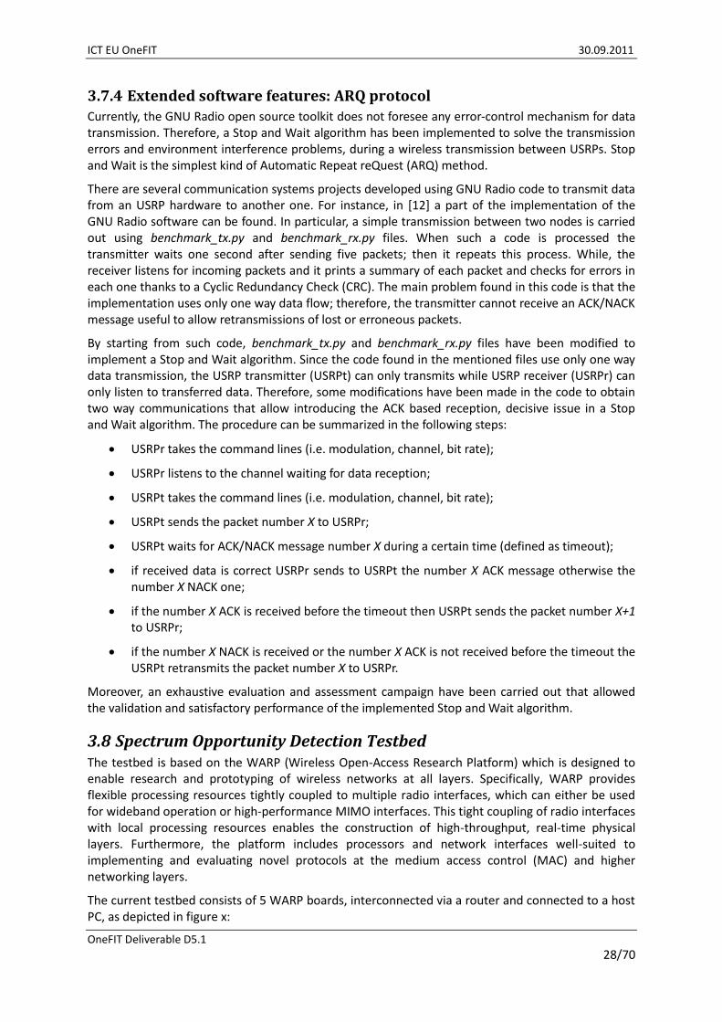
3.7.4 Extended software features: ARQ protocol Currently, the GNU Radio open source toolkit does not foresee any error-control mechanism for data transmission. Therefore, a Stop and Wait algorithm has been implemented to solve the transmission errors and environment interference problems, during a wireless transmission between USRPs. Stop and Wait is the simplest kind of Automatic Repeat reQuest (ARQ) method.
There are several communication systems projects developed using GNU Radio code to transmit data from an USRP hardware to another one. For instance, in [12] a part of the implementation of the GNU Radio software can be found. In particular, a simple transmission between two nodes is carried out using benchmark_tx.py and benchmark_rx.py files. When such a code is processed the transmitter waits one second after sending five packets; then it repeats this process. While, the receiver listens for incoming packets and it prints a summary of each packet and checks for errors in each one thanks to a Cyclic Redundancy Check (CRC). The main problem found in this code is that the implementation uses only one way data flow; therefore, the transmitter cannot receive an ACK/NACK message useful to allow retransmissions of lost or erroneous packets.
By starting from such code, benchmark_tx.py and benchmark_rx.py files have been modified to implement a Stop and Wait algorithm. Since the code found in the mentioned files use only one way data transmission, the USRP transmitter (USRPt) can only transmits while USRP receiver (USRPr) can only listen to transferred data. Therefore, some modifications have been made in the code to obtain two way communications that allow introducing the ACK based reception, decisive issue in a Stop and Wait algorithm. The procedure can be summarized in the following steps:
USRPr takes the command lines (i.e. modulation, channel, bit rate);
USRPr listens to the channel waiting for data reception;
USRPt takes the command lines (i.e. modulation, channel, bit rate);
USRPt sends the packet number X to USRPr;
USRPt waits for ACK/NACK message number X during a certain time (defined as timeout);
if received data is correct USRPr sends to USRPt the number X ACK message otherwise the number X NACK one;
if the number X ACK is received before the timeout then USRPt sends the packet number X+1 to USRPr;
if the number X NACK is received or the number X ACK is not received before the timeout the USRPt retransmits the packet number X to USRPr.
Moreover, an exhaustive evaluation and assessment campaign have been carried out that allowed the validation and satisfactory performance of the implemented Stop and Wait algorithm.
3.8 Spectrum Opportunity Detection Testbed The testbed is based on the WARP (Wireless Open-Access Research Platform) which is designed to enable research and prototyping of wireless networks at all layers. Specifically, WARP provides flexible processing resources tightly coupled to multiple radio interfaces, which can either be used for wideband operation or high-performance MIMO interfaces. This tight coupling of radio interfaces with local processing resources enables the construction of high-throughput, real-time physical layers. Furthermore, the platform includes processors and network interfaces well-suited to implementing and evaluating novel protocols at the medium access control (MAC) and higher networking layers.
The current testbed consists of 5 WARP boards, interconnected via a router and connected to a host PC, as depicted in figure x:

ICT EU OneFIT 30.09.2011
OneFIT Deliverable D5.1
29/70
Figure 18: Physical layout of the testbed
Up to 16 WARP nodes and a host PC running MATLAB can be connected to a switch via Ethernet links. The Ethernet links are used to transfer data to and from the WARP nodes. Each board can be configured with up to 4 radio daughterboards to provide 4x4 MIMO functionality.
3.8.1 WARP Platform
The WARP board has a Xilinx Virtex-4 FPGA, with the provision of supporting up to four daughter boards with RF front-ends. Multiple WARP boards may be connected to the host PC via an Ethernet switch. An interesting deviation from the USRP-based architecture is the ability to construct the baseband samples in MATLAB and then store them in buffers on the FPGA on the transmitter side before beginning the transfer.
A trigger signal from the host can initiate the transmission of the samples to the receiver side over the wireless channel. The WARP board supports 40 MHz of bandwidth independent of the carrier frequency. The two embedded PowerPC processors provide sufficient onboard computational power, while the 328 18-kbit block RAM allows for fast access of data from within the FPGA. The onboard processing ability of the WARP platforms allows some time-critical tasks to be completed within the board itself, facilitating time-sensitive operations discussed later. The key benefit of using WARP is ease of prototyping enabled by the WARPlab framework. This framework provides the software that allows controlling and programming the individual nodes from within the MATLAB workspace running on the host computer. The WARPlab framework itself has three components: The platform studio generates the implementations of the network protocols (assumed to be input in C/C++). The system generator takes the MATLAB-specified physical layer algorithms, and converts them to a hardware model for the FPGA implementation. Finally, it has a low-level HDL and ASIP development module that exposes the internal hardware components to the higher-layer MATLAB routines. Extensive software support is also available for WARP toward advanced networking functionalities e.g. carrier sense multiple access (CSMA) based protocols, spectrum management, MIMO, cooperative communication, power control, and energy-efficient transmission through published works and downloadable code. Some other key features include: RF front end supports 2.4GHz and 5GHz with the standard RF boards, however other daughter
boards can be added to extend frequency range Reconfiguration time is in order of a few microseconds Two interfaces are available – GiG/Ethernet to connect with the host PC & USB (to download
code into the board) 2 PowerPC cores are available on WARP for increased performance (PPC1, PPC2)

ICT EU OneFIT 30.09.2011
OneFIT Deliverable D5.1
30/70
MAC/PHY typically embedded in one PPC whilst code for other layers resides in the other core, so host is only needed to send data
If one node shuts down, system can reconfigure (network layer is also implemented in LE-WARP and it can send update/status information periodically (e.g. after each 1ms interval)
To embed Linux (Network layer and other higher layers) in processor core, some experience with embedded controller programming is essential (No need for VHDL programming though)
Physical layer is implemented using WARPlab but for MAC & NETWORK layers “Xilinx platform studio” (used to program the FPGA on WARP) is used
o In the simplest case, if NET and higher layers are implemented on host then we can use WARP boards as is with PHY/MAC (use one PPC)
WARPlab is software tool mainly for non-real time communications and totally based on MATLAB.
The following sections outline details of the hardware and the software environment/framework, as used on the WARP platform.
3.8.2 Hardware
There are several boards that makeup the WARP kits. Standard kits consist of:
FPGA Board (mother board),
Daughterboards: o Radio Board(s), o Analogue Board o Memory Board, o I/O board, o Clock Board.
3.8.2.1 WARP FPGA Board - Overview
The WARP FPGA board is a 8"x8" PCB built around a Xilinx XC4VFX100FFG1517-11C Virtex-4 FPGA. The next sections detail the various components and configuration options on the board. The physical layout of the board and components is depicted in figure x below.

ICT EU OneFIT 30.09.2011
OneFIT Deliverable D5.1
31/70
Figure 19: Physical layout of a WARP board equipped with (max.) 4 radio daughterboards
The WARP FPGA Board v2.2 is designed around the Xilinx Virtex-4 XC4VFX100FFG1517-11C FPGA.
Part XC4VFX100
Package FFG1517 (1517 pin 1mm pitch BGA)
Speed Grade 11 (middle grade)
Temperature Range C (commercial)
The resources of the V4FX100 FPGA are summarized below:
Logic Slices 42k
DSP48 Slices 160
Block RAMs 376
PowerPC Cores 2
Tri-mode Ethernet MACs 4
3.8.2.1.1 WARP FPGA Board Power Supplies
Required External Supply - The WARP FPGA board operates from a single external 12v supply. This supply is generally connected to the board's coaxial power connector. This connector requires a mating female connector with an inner diameter of 2.1mm, outer diameter of 5.5mm, positive tip and grounded shell.

ICT EU OneFIT 30.09.2011
OneFIT Deliverable D5.1
32/70
FPGA Power Supplies - The Virtex-4 FPGA has a number of different power inputs. The WARP FPGA board uses switching voltage regulators for the 5v, 3.3v, 1.8v and 1.2v supplies. The table below summarizes the power supplies on the WARP FPGA board. Supply Voltage Description
VCC_EXT 12v External supply
VCC_5 5.0v Daughtercard slot supply
VCC_INT 1.2v FPGA core logic
VCC_AUX 2.5v FPGA clock resources
VCC_O 3.3v, 2.5v & 1.8v FPGA I/O banks
MGT_x 2.5v, 1.5v & 1.2v MGT logic and I/O
VCC_0.9 0.9v DDR2 SO-DIMM termination
Daughtercard Power Supplies - The four daughtercard slots on the WARP FPGA board are supplied with 5v by a dedicated 18A switching regulator. A second power plane is also connected to the daughtercard slots and can be driven by an off-board supply via a dedicated 6-pin header on the FPGA board (J31). This header is not mounted by default.
3.8.2.1.2 WARP FPGA Board Clocking
On-board Oscillators - The FPGA board has two oscillator footprints for general clocks. By default, one 100MHz oscillator is mounted (component Y7) and one footprint is left empty (component Y9) for future customization. Both oscillator footprints are connected to global clock (GCLK) pins on the FPGA. Off-board Clock Sources - The FPGA board has a header dedicated to off-board clocks. This header (component J25) is used by the WARP clock Board. The header connects to two global clock (GCLK) pairs on the FPGA (allowing for differential clocks), the 3.3v power plane and 8 general FPGA I/O.
3.8.2.1.3 WARP FPGA Board Memory Resources
On-Chip Memory - The V4 FX100 FPGA provides 376 18kb RAM blocks (6.7Mb total) on-chip. Logic slices can also be used as RAM (Xilinx calls this distributed memory); the FX100 provides up to 659kb of distributed memory. DDR2 SO-DIMM - The WARP FPGA Board v2.2 includes a DDR2 SO-DIMM slot. This connector is routed to dedicated FPGA I/O and clocking resources and supports up to 2GB modules. In order to use the SO-DIMM, the user FPGA design must include a DDR2 memory controller. Xilinx provides (and maintains) a high performance controller as part of their Multi-Port Memory Controller (MPMC). There are a large number of pins and parameters involved in instantiating the MPMC in a design.
3.8.2.2 WARP Radio Board - Overview & Architecture
The radio daughterboard(s) comprise of:
D/A converter: 160MS/s, 16-bit dual DACs (AD9777)
I/Q A/D Converter: 65MS/s, 14-bit dual-ADC (AD9248)
RSSI A/D Converter: 20MS/s, 10-bit ADC (AD9200)
RF Transceiver (MAX2829)
Dual band PA

ICT EU OneFIT 30.09.2011
OneFIT Deliverable D5.1
33/70
Antenna ports & connectors
Figure 20: WARP radio daughterboard (2.4 / 5 GHz; 40 MHz bandwidth)
Figure 21: WARP radio daughterboard block diagram architecture
3.8.2.2.1 WARP Radio Board Clocking
Figure 22: WARP radio daughterboard – clocks.

ICT EU OneFIT 30.09.2011
OneFIT Deliverable D5.1
34/70
There are three clock domains on the Radio Board, as described below. RF Reference Clock
The MAX2829 transceiver requires a reference clock which is multiplied up by its PLL to form the RF carrier. This must be a 20MHz or 40MHz clock and must be driven into the Radio Board's MMCX jack. In standard WARP kits, the WARP Clock Board drives this signal at 20MHz. If multiple Radio Boards are driven by the same RF reference clock, their RF carriers will be synchronous, though there will be a phase offset resulting from their PLLs locking at different times. I/Q Sampling Clock
I/Q ADCs and DACs are driven by a common clock. This clock is produced on an on-board clock buffer (an Analog Devices AD9513). The source clock for this buffer comes from an off-board source driven into a 4-pin connector. In standard WARP kits, the WARP Clock Board drives this signal at 40MHz. If multiple Radio Boards are used on a single kit, they should all be driven by synchronous and in-phase sampling clocks. RSSI Sampling Clock
The dedicated RSSI ADC is clocked from the FPGA via the daughtercard headers. Any frequency up to 20MHz is valid. There is no requirement for this clock to be synchronous with other clocks on the Radio Board.
3.8.2.2.2 WARP Radio Board RF
Figure 23: WARP radio daughterboard – RF.

ICT EU OneFIT 30.09.2011
OneFIT Deliverable D5.1
35/70
The RF section of the Radio Board consists of a dual-band direct-conversion RF transceiver and an RF front-end connecting the transceiver to the antenna. RF Transceiver - The board uses Maxim's MAX2829 dual-band transceiver. Some key features of the transceiver are:
Dual-band (2400-2500MHz, 4900-5875MHz) Up to 40MHz bandwidth Analog I/Q Tx and Rx interfaces 60dB RSSI range 30dB Tx power control range 93dB Rx gain control range MIMO capable
I/Q interfaces of the MAX2829 are connected directly to the Radio Board's ADC and DAC. The transceiver's control interfaces are connected to the daughtercard headers, enabling direct control from the FPGA. RF Power Amplifier - The RF transmit path includes a Sharp IRM046U7 dual-band RF power amplifier. The board is designed to provide approximately 18dBm output power when driven at full gain. The PA is controlled by the host FPGA via daughtercard connections. Antenna Ports - There are two 50Ω female SMA antenna connectors; only one is connected to the transceiver at a given time.
3.8.3 Software
There are two primary flows that are used during development and for investigating new ideas in physical layer space. All non-real-time (PHY layer) system implementations make use of WARPLab environment. This makes real-time use of the channel but all the transmitter and receiver processing is done offline in MATLAB. This is a good beginning when trying new physical layer ideas. All real-time system (PHY layer) implementations are developed in System Generator. This is a block based design tool for MATLAB's Simulink. It is provided by Xilinx and generates corresponding HDL once synthesized.
Figure 24: Design flows
The real-time design flow starts at the System Generator layer but also must include the layers above, e.g. C/C++ code in the PowerPC used to implement a MAC to control the physical layer.

ICT EU OneFIT 30.09.2011
OneFIT Deliverable D5.1
36/70
3.8.3.1 WARPLab Framework Overview
WARPLab is a framework which brings together WARP and MATLAB. With WARPLab, developers can interact with WARP nodes directly from the MATLAB workspace and signals generated in MATLAB can be transmitted in real-time over-the-air using WARP nodes. This facilitates rapid prototyping of physical layer (PHY) algorithms. The WARPLab setup is shown in the following figure.
Figure 25: WARPLab setup
The design flow for a new PHY is the following: The user creates in MATLAB the samples to be transmitted as part of the custom PHY. The samples to be transmitted are downloaded to buffers in the nodes assigned as
transmitters. The user sends a trigger to transmitter and receiver nodes. Upon reception of this trigger,
samples are transmitted over-the-air and captured in real-time. The user reads captured samples from the receiver nodes to the MATLAB workspace. Received samples are processed offline in MATLAB
In order to allow rapid prototyping, the WARPLab framework provides the following:
WARPLab XPS Reference Design: The bitstream ('.bit' file) to program the WARP nodes and the WARPLab Xilinx Platform Studio (XPS) Reference Design to generate this bitstream,
WARPLab Reference M-Code: M-Code functions that facilitate interaction with WARP nodes directly from MATLAB workspace,
The WARPLab framework facilitates experimental evaluation of PHY layer algorithms. However, some novel algorithms may require features not provided in the WARPLab framework. Users are encouraged to modify/extend the WARPLab XPS Reference Design and WARPLab Reference M-Code. For example, if part of the signal processing cannot be done offline in MATLAB but must be done in real-time, then this signal processing can be implemented in FPGA logic by modifying the WARPLab XPS Reference Design. Depending on the experiment, the users may also have to modify the WARPLab Reference M-Code.
3.8.3.1.1 WARPLab FPGA Design Architecture
Tx and Rx paths for one antenna are shown in the figure below, blocks in the Tx Path are highlighted in pink and blocks in the Rx path are highlighted in blue. The blocks are described below.

ICT EU OneFIT 30.09.2011
OneFIT Deliverable D5.1
37/70
Figure 26: WARPLab sysgen core and radio board block diagram
Blocks on transmitter path: Tx I/Q Buffers: In-Phase samples to be transmitted are stored in the Tx I Buffer and
Quadrature samples to be transmitted are stored in the Tx Q Buffer. DAC I/Q: Digital-to-Analog Converters for In-Phase/Quadrature samples. Tx BB Amplifiers: Transmitter Base Band Amplifiers. There are two amplifiers, one for the I
signal and one for the Q signal. These are variable Gain Amplifiers both set to the same gain value which can be input by the user from MATLAB workspace.
Upconversion: Converts the base band signal to an RF signal. Carrier frequency depends on PLL setting.
Tx RF Amplifiers: Transmitter RF amplifier, variable gain amplifier, gain value can be input by the user from MATLAB workspace.
Blocks on receiver path: Rx RF Amplifier: Receiver RF amplifier, variable gain amplifier, gain value can be input by the
user from MATLAB workspace. Downconversion: Converts the RF signal to base band In-Phase/Quadrature signals.
Downconversion from RF depends on PLL setting. Rx BB Amplifiers: Receiver Base Band Amplifiers. There are two amplifiers, one for the I
signal and one for the Q signal. These are variable Gain Amplifiers both set to the same gain value which can be input by the user from MATLAB workspace.
RSSI: Received Signal Strength Indicator. This block measures the RSSI. ADC I/Q: Analog-to-Digital Converters for In-Phase/Quadrature samples. ADC RSSI: Analog-to-Digital Converter for the measured RSSI. The RSSI data is available at
1/4th the rate of the I/Q data. Rx I/Q Buffers: Received In-Phase samples are stored in the Rx I Buffer and Received
Quadrature samples are stored in the Rx Q Buffer. RSSI Buffer: RSSI data is stored in this buffer.
PLL block: Setting of the PLL determines the carrier frequency which can be set to any of the 14 channels in the Wi-Fi 2.4 GHz band or 23 channels in the 5 GHz band. The carrier channel can be set directly from the MATLAB workspace.

ICT EU OneFIT 30.09.2011
OneFIT Deliverable D5.1
38/70
3.9 Mesh Networking Testbed LCI mesh networking test-bed is based on MikroTik router-boards RB800 and RB433AH. The RB800 is an advanced high performance wireless platform.
Key features:
CPU: MPC8544 800MHz network processor
Memory: 256MB DDR2 SDRAM onboard memory
Boot loader: Router-BOOT
Data storage: 64MB onboard NAND memory chip
Compact-Flash slot: One Compact-flash slot on reverse (True IDE Micro-drive supported)
Ethernet: Three 10/100/1000Mbit/s Ethernet ports with Auto-MDI/X
MiniPCI interfaces: 4 x mini PCI, 1 x mini PCI-e
Serial port: One DB9 RS232C asynchronous serial port, one IDC10 serial connector
Operating System: MikroTik RouterOS v5, Level6 license
Dimensions: 14cmx20cm, 285g
Power options:
o PoE: 36-56V DC (including power over data lines)
o Power jack: 10-56V DC
Expansion: regular PCI daughterboard, PCI-e daughterboard port
LEDs: Power and user LED
Pictures of LCI open platform as well as layout view of system board are given below.
Figure 27: LCI open platform wireless mesh access point

ICT EU OneFIT 30.09.2011
OneFIT Deliverable D5.1
39/70
Figure 28: Mesh networking testbed layout.
LCI open platform wireless mesh access point supports 802.11a/b/g wireless standards using following wireless interfaces:
Two Wistron Neweb CM9 cards
o Radio operations: IEEE 802.11b/g, 2.4GHz, IEEE 802.11a, 5GHz
o Host interface: miniPCI version 1.0 Type IIIB
o Antenna ports: 2xUFL Ultra-miniature coaxial connectors
o Security: 64/128/152bit WEP, 802.1x authentication, AES-CCM & TKIP encryption
o Data rates:
802.11 b/g: 1, 2, 5.5, 11Mbps, auto-fallback, up to 54Mbps
802.11g (Super mode): up to 108Mbps
802.11a (Normal mode): 6, 9, 12, 18, 24, 36, 48, 54Mbps
802.11a (Turbo mode): 12, 18, 24, 36, 48, 72, 96, 108Mbps
o Output power:
802.11b: 18dBm
802.11g: 18dBm@6Mbps, 15dBm@ 54Mbps
802.11a: 17dBm@6Mbps, 13dBm@54Mbps
o Operation distance (depends on antenna performance):

ICT EU OneFIT 30.09.2011
OneFIT Deliverable D5.1
40/70
802.11a: Outdoor: 85m@54Mbps, 300m@6Mbps; Indoor: 20m@54Mbps, 40m@6Mbps
802.11b: Outdoor: 300m@11Mbps, 400m@1Mbps; Indoor: 30m@11Mbps, 50m@1Mbps
802.11g: Outdoor: 80m@54Mbps, 300m@6Mbps; Indoor: 15m@54Mbps, 35m@6Mbps
Two Ubiquiti XtremeRange 5 cards (XR5)
o Chipset: Atheros, 6th Generation, AR5414 with SuperA/Turbo Support
o Radio operation: IEEE 802.11a, 5GHz
o Interface: 32-bit miniPCI Type IIIA
o Antenna ports: Single MMCX
o Security: WPA, WPA2, AES-CCM & TKIP Encryption, 802.1x, 64/128/152bit WEP
o Data rates: 6Mbps, 9Mbps, 12Mbps, 24Mbps, 36Mbps, 48Mbps, 56Mbps
o TX channel width support: 5MHz/10MHz/20MHz/40MHz(turbo)
o Output power: 600mW
o Range performance:
Indoor (antenna dependent): Up to 150m
Outdoor (antenna dependent): Over 50km
LCI open platform wireless mesh AP has four dual band (2.4GHz and 5GHz) 3dBi omni-directional antennas. RB800 can be extended using regular PCI daughterboard or PCI-e daughterboard, so more wireless cards supporting 802.11a/b/g/n standards can be added.
Figure 29: Block diagram of LCI open platform wireless mesh AP
Software architecture of RB800 open platform is based on RouterOS which is a stand-alone operating system based on the Linux v2.6 kernel. The main purpose of RouterOS is building routers
ICT EU OneFIT 30.09.2011
OneFIT Deliverable D5.1
41/70
and other network components with all the necessary features: routing, firewall, bandwidth management, wireless access point, backhaul link, hotspot gateway, VPN server and more.
Major features offered by RouterOS:
Powerful QoS control
P2P traffic filtering
Bonding and interfaces
Advanced QoS
Stateful firewall, tunnels
STP bridging with filtering
High speed 802.11 a/b/g/n wireless
WDS and Virtual AP
HotSpot for Plug-and-Play access
RIP, OSPF, BGP, MPLS, HWMP+, VRF, ECMP, policy based routing
Costume made proxy server for caching web resources
Remote WinBox GUI and Web admin
Telnet/mac-telnet/ssh/console admin
API for programming your own tools
Real-time configuration and monitoring
There are two approaches when configuring RouterOS:
Local configuration using Serial Console an Terminal tools
Remote configuration using Telnet, SSH, WinBox console or Webbox
Important feature of RouterOS is MetaRouter which has the ability to import custom built images. MetaRouter allows OpenWRT to be patched and used as a virtual machine on RB800. OpenWRT is described as a GNU/Linux distribution for embedded devices.
Key features of RB433AH are:
CPU: Atheros AR7161 680MHz
Memory: 128MB DDR SDRAM onboard memory
Boot loader: Router-BOOT
Data storage: 64MB onboard NAND memory chip
Ethernet: Three 10/100/1000Mbit/s Ethernet ports supporting Auto-MDI/X
MiniPCI slot: 3 x mini PCI type IIIA/IIIB slots
Serial port: One DB9 RS232C asynchronous serial port
Power options:
o Power over Ethernet 10..28V DC (except power over datalines)
o Power jack: 10..28V DC
Dimensions: 105mm x 150mm, 140g

ICT EU OneFIT 30.09.2011
OneFIT Deliverable D5.1
42/70
LEDs: Power and user LED
Figure 30: RB433AH board view
Figure 31: RB433AH layout
RB433AH supports 802.11a/b/g wireless standards using following wireless interfaces:
Three MikroTik R52H high power wireless mini-PCI cards:
o Chipset: Atheros AR 5414
o Standards: IEEE 802.11a/b/g

ICT EU OneFIT 30.09.2011
OneFIT Deliverable D5.1
43/70
o Media access: CSMA/CA with ACK architecture 32-bit MAC
o Security: Hardware-based 64/128 bit WEP, TKIP and AES-CCM encryption WPA,
WPA2, 802.11x
o Modulations: 802.11b+g: DSSS, OFDM for data rate >30Mbps, 802.11a: OFDM
o Connectors: two UFL connectors
o Wi-Fi: WECA Compliant
o Supported OS: MikroTik RouterOS, Windows XP, GNU/Linux
o Transfer data rate:
802.11 b/g: 1, 2, 5.5, 11Mbps, auto-fallback, up to 54Mbps
802.11g (Turbo mode): up to 108Mbps
802.11a (Normal mode): 6, 9, 12, 18, 24, 36, 48, 54Mbps
802.11a (Turbo mode): 12, 18, 24, 36, 48, 72, 96, 108Mbps
o Output power/ receive sensitivity:
IEEE 802.11a: 24dBm / -90dBm @ 6Mbps, 19dBm / -70dBm @ 54Mbps
IEEE 802.11b: 25dBm / -92dBm @ 1Mbps, 25dBm / -87dBm @ 11Mbps
IEEE 802.11g: 25dBm / -90dBm @ 6Mbps, 20dBm / -70dBm @ 54Mbps
Software architecture of RB433AH is based on OpenWRT Backfire rc4 OS which is based on the Linux v2.6 kernel. Configuration of RB433AH can be done in two ways:
By using serial console and terminal tools
By using web based GUI interface, called LuCI, which has been installed on OpenWRT
By using OpenWRT different routing algorithms can be implemented and tested on RB800. With combined use of RouterOS and OpenWRT great number of major features needed for validation of OneFIT use cases can be achieved.
LCI mesh networking testbed also include wireless mesh network deployed on campus at University of Novi Sad. LCI WMN consists of 5 Arrow Span MeshAP3800 which provide broadband internet access to students and professors. Each MeshAP3800 can work as mesh station or mesh manager. Currently two mesh APs work as GWs.
Key features of MeshAP3800:
Backhaul mesh radio
o Number of radios: 3
o Standards: IEEE 802.11a
o Frequency bands: 4.9-5.091GHz, 5.470-5.725GHz, 5.725-5.850GHz
o Data rates: 6, 9, 12, 18, 24, 36, 48, 54Mbps
o TX radio power: up to 27dBm
o Antenna: 3x 8dBi 5GHz omni directional antenna
Access point radio
o Number of radios: 1
o Standards: IEEE 802.11b/g
o Frequency bands: 2.4-2.462GHz

ICT EU OneFIT 30.09.2011
OneFIT Deliverable D5.1
44/70
o Data rates:
802.11g: 6, 9, 12, 18, 24, 36, 48, 54Mbps
802.11b: 1, 2, 5.5, 11Mbps
o TX radio power: up to 27dBm
o Antenna: 8dBi 2.4GHz omni directional antenna
Operating range:
o Mesh backhaul: node-to-node distance 304m@54Mbps
o 802.11b/g AP: 150m@54Mbps, 500m@6Mbps
Mesh backhaul performance: Up to 30Mbps mesh backhaul throughput at the 5th hop count
Security and encryption: 64, 128bit WEP; WPA/WPA-2, Mesh ID protection, MAC based filter, Radius support, Multi-level mesh operator username/password
LCI WMN will be used for gathering useful information about behavior and needs of end users. Information on type of end users (professors/students), their local geo-location and time based behavior in term of used applications and requested throughput, frequent requests for same multimedia files and periodical repeats of backhaul congestions will be used for developing multipath routing algorithms and improving cognitive based caching on wireless mesh APs.
LCI network supports both centralized and distributed system management. We will use first approach, because it reduces the number of contextual messages which will be exchanged among APs thus reducing control overhead and saving network resources. All necessary information about state of network will be collected and sent to network manager/mesh wireless controller by APs. Network manager has a large computing power which allows it to spend less time on processing contextual messages thus giving him ability to deliver real-time decisions. On the basis of the provided information network manager evaluate performance of the network and decide whether or not to selectively activate or deactivate specific networking/infrastructure functionalities across group of wireless access network elements.
For purpose of centralized management mesh wireless controller MWC-1000 will be used. MWC-1000 wireless controller provides all needed software features for service provider to manage wireless network covering from layer 3 to layer 7 management functions.
Major features and functions of MWC-1000 are:
Hardware
o 6x10/100/1000TX RJ-45 Ethernet ports
o Console
o 500G HDD
o 100Mbps throughput with layer 7 function
Routing and security
o Support VLAN
o NAT/PAT
o DHCP server, relay
o Support bridging and routing

ICT EU OneFIT 30.09.2011
OneFIT Deliverable D5.1
45/70
o Firewall can identify and control up to 600 applications like P2P, VoIP, video, HTTP, game, database firewall
AAA Authentication
o Web authentication: local database, POP3, 802.1x, LDAP, Radius
o Support IP/MAC locking and VLAN ID binding for authentication
o User level grouping
o Allow multiple authentication for same user
o User name/IP mapping table
o Individual bandwidth allocation authentication control
o Individual connection time control
Bandwidth control, layer 3 to layer 7
o IP based bandwidth control
o Application based bandwidth control
o Setting level of maximum bandwidth, guarantee bandwidth priority bandwidth, bandwidth rental
o Monitor bandwidth usage status table
Wireless management
o Authentication & encryption: WEP, WPA/WPA2 (TKIP, AES)
o VLAN compatibility 802.11p/q
o 802.11a/b/g
o Mesh ID routing protection setting
o Auto/manual channel selection
o GPS location information of node recording
o Mesh topology and topology change log
o User list per AP, per Mesh

ICT EU OneFIT 30.09.2011
OneFIT Deliverable D5.1
46/70
4. Proof-of-Concept Components
4.1 Proof-of-Concept Architecture The OneFIT PoC Architecture is illustrated in Fig. 3. The validation of the PoC will be performed in the sequel; in this context, the role of the various PoC Architecture building blocks will be detailed for each of the OneFIT Scenarios which are currently in the focus for the demonstration development: Scenario 1 (Opportunistic coverage extension), Scenario 2 (Opportunistic capacity extension) and Scenario 5 (Opportunistic resource aggregation in the backhaul network).
As a basis for this analysis, the system requirements for the OneFIT system are used as they are introduced by WP2 in D2.1 and D2.2 [2][3]. A summary of these requirements is given in Table 2. The requirements are grouped into general requirements (numbered with “G”), user and service related requirements (“U”), opportunistic network management requirements (“M”), related algorithm requirements (“A”), protocol requirements (“P”) and security requirements (“S”).
Category Nbr. Title of the requirement
General requirements
G1 Communication with the infrastructure
G2 Communication between terminals
G3 Versatile spectrum use
G4 Versatile RAT/RAN use
G5 Mobility
G6 Relaying
G7 Creation of opportunistic networks
G8 Opportunistic Networks controllable by single operator
G9 Preservation of legacy RAN operation
G10 Compatibility with legacy RAN deployments
G11 Resource efficiency
User and Service related requirements
U1 Hide complexity from the end user
U2 User’s service perception
U3 Availability of ON-related information to the service layer
Opportunistic network Management related requirements
M1 Identification of the need for an opportunistic network
M2 Suitability determination
M3 Creation of opportunistic networks
M4 Connection set-up
M5 Maintenance of opportunistic networks
M6 Release of opportunistic networks
M7 Coordination of opportunistic networks with the infrastructure
M8 Opportunistic network identification
M9 Maximum size of an opportunistic network
M10 Coexistence of opportunistic networks
M11 Assignment of bandwidth
Algorithm related requirements
A1 Context awareness
A2 Decision making
A3 Routing
A4 ON Advertisement

ICT EU OneFIT 30.09.2011
OneFIT Deliverable D5.1
47/70
Protocol requirements
P1 Protocol usage
P2 Broadcast/Multicast
P3 Unicast/Dedicated addressing
P4 Secure as well as unsecure communication
P5 Protocol efficiency
Security requirements
S1 Security
S2 Accountability, charging and billing
S3 Protection of user identity
S4 Protection of device identity
Table 2: List of the OneFIT System requirements.
4.2 Instantiation of Proof-of-Concept Architecture The instantiation of the PoC Architecture will be presented in the sequel. This exercise illustrates the relationship of the abstract PoC Architecture components to the actual available HW/SW and related implementation tasks.
4.2.1 Mobile Device Instantiation
The instantiation of the Mobile Device is illustrated below. Several platforms are used for the prototyping activities, including
A Laptop with WiFi/3G capabilities building on an IMC 3G modem,
A USRP/GNU Radio platform adapted in particular to spectrum measurement tasks,
An Android Smartphone with WiFi/3G capabilities,
A Smartphone with Terminal Agents being implemented.
Figure 32: Mobile Device Instantiation.

ICT EU OneFIT 30.09.2011
OneFIT Deliverable D5.1
48/70
4.2.2 Femto BS Instantiation The instantiation of the Femto BS is illustrated below. In particular the following components are available and/or under development:
Wireshark Debug Tool,
Initial Configuration interface via HTTP,
User and Session Maagement,
Femto Network Context Controller.
Figure 33: Femto BS Instantiation.
4.2.3 Infrastructure Instantiation The instantiation of the Infrastructure components is illustrated below. In particular two platforms are employed:
An agents based platform for Network Management tasks,
USRP/GNU Radio platform adapted in particular to spectrum measurement tasks.
Figure 34: Infrastructure Instantiation.

ICT EU OneFIT 30.09.2011
OneFIT Deliverable D5.1
49/70
4.2.4 WiFi/Mesh-Network Instantiation The instantiation of the WiFi/Mesh-Network is illustrated below. In particular, two platforms are employed:
A WiFi Mesh Network platform building on MikroTik components type RB800 ad RB433AH,
A FPGA platform using XILINX software and WARPLab.
Figure 35: WiFi/Mesh Network Instantiation.
4.3 Instantiation of Scenarios The instantiation of the OneFIT Scenarios as derived in [2] and building on the PoC Architecture will be presented in the sequel. This exercise illustrates how the various HW/SW components provided by the OneFIT consortium will be used in order to validate the various scenarios. At the current state of the project, the focus is on the following Scenarios:
• Scenario 1 “Opportunistic coverage extension”: A device cannot connect to the network operator’s infrastructure, due to lack of coverage or a mismatch in the radio access technologies.
• Scenario 2 “Opportunistic capacity extension”: A device cannot access the operator infrastructure due to the congestion of the available resources at the serving access node.
• Scenario 3 “Infrastructure supported opportunistic ad-hoc networking”: Involves closely located devices which have common application interests.
• Scenario 4 “Opportunistic traffic aggregation in the radio access network”: Use of opportunistic networks to aggregate traffic in the radio access network.
• Scenario 5 “Opportunistic resource aggregation in the backhaul network”: Use of opportunistic networks to aggregate backhaul bandwidth on access side.
Scenarios 3 and 4 will be addressed in a later stage of the project.
4.3.1 Dynamic Spectrum Management The Dynamic Spectrum Management (DSM) functionality involves the management of available frequency bands by providing registration to each BS and Femto AP. To that respect, the DSM functionality is addressed in all the OneFIT defined scenarios. The addressed general requirements

ICT EU OneFIT 30.09.2011
OneFIT Deliverable D5.1
50/70
are the versatile spectrum use (G3), versatile RAT/RAN use (G4), the ONs controllable by a single operator (G8) and the resource efficiency (G11). The ON management related requirements are the suitability determination (M2), coexistence of ONs (M10) and the assignment of bandwidth (M11). Finally, the algorithm related requirement is the context awareness (A1). The figure below depicts the relationship of components to PoC architecture.
Each BS/ Femto AP
registers its used/
supported frequencies
with DSM
Figure 36: Dynamic Spectrum Management – Relationship to PoC Architecture.
The key component that is related to spectrum scanning is exploited for the identification of spectrum opportunities. A typical scanning result as used in the PoC environment is illustrated below.
Figure 37: PoC Architecture component for addressing basic ON mechanisms: Illustration of Spectrum Measurement Results.
This component has already been developed and implemented to the customized OneFIT system platform. In addition, it has been showcased in various demonstration events such as Future Network & Mobile Summit and Future Internet Weeks.
4.3.2 Opportunistic Coverage Extension
ON based opportunistic coverage extension is demonstrated on a SW platform environment as illustrated in Figure 38.
This PoC component performs the following tasks:
Initially, all Macro BSs are functioning properly and all mobile devices are properly served. ON is not needed yet.

ICT EU OneFIT 30.09.2011
OneFIT Deliverable D5.1
51/70
A Macro BS experiences failure. As a result, mobile devices are left without coverage. ON is started forming up in order to serve the out of infrastructure terminals. Mobile devices are connected to each other in order to gain access to the infrastructure.
When the previously failed Macro BS goes back online, ON is not needed anymore and it is terminated.
The addressed general requirements are the communication with the infrastructure (G1), the communication between terminals (G2), the versatile RAT/RAN use, mobility (G5), relaying (G6), the creation of ONs, the preservation of legacy RAN operation (G9), the compatibility with legacy RAN deployments and the resource efficiency (G11). The addressed ON Management related requirements are the identification of the need for an ON (M1), the suitability determination (M2), the creation of ONs (M3), the connection set-up (M4), the maintenance of ONs (M5), the release of ONs (M6), the coordination of ONs with the infrastructure (M7) and the coexistence of ONs (M10). Finally, the addressed algorithm related requirements are the context awareness (A1), the decision making (A2) and the ON advertisement (A4). Figure 39 depicts the relationship of components to PoC architecture.
Figure 38: Coverage-Extension by D2D Communication.

ICT EU OneFIT 30.09.2011
OneFIT Deliverable D5.1
52/70
This component has already been developed and implemented to the customized OneFIT system platform. Moreover, it has been showcased in various demonstration events such as Future Network & Mobile Summit and Future Internet Weeks.
Figure 39: Coverage extension – Relationship to PoC Architecture.
4.3.3 Opportunistic Capacity Extension, solution of a maximum-flow problem
Capacity extension mechanisms in an outdoor environment are showcase in a SW environment as illustrated in Figure 40.
This PoC component performs the following tasks:
Infrastructure elements experience congestion problems and traffic hotspots are identified.
The DSONPM, CSCI and CMON collaborate in order to solve congestion by redirecting terminals with ON capabilities to alternate BSs.
Terminals of the congested area with ON capabilities find paths to alternate BSs through other terminals with ON capabilities in non-congested and congested area.
A Macro BS starts experiencing traffic congestion issues. Femtocells are also available in the area.
As soon as the Macro BS gets congested, the DSONPM is notified and CSCIs, CMONs collaborate in order to redistribute traffic to uncongested cells in the area.
As a result, traffic is re-assigned to available femtocells and the congestion situation is resolved.
The addressed general requirements are the communication with the infrastructure (G1), the communication between terminals (G2), the versatile RAT/RAN use (G4), relaying (G6), the creation of ONs (G7), the preservation of legacy RAN operation (G9), the compatibility with legacy RAN deployment (G10) and the resource efficiency (G11). The addressed ON Management related requirements are the identification of the need for an ON (M1), the suitability determination (M2), the creation of ONs (M3), the connection set-up (M4), the maintenance of ONs (M5), the release of ONs (M6), the coordination of ONs with the infrastructure (M7) and the coexistence of ONs (M10). Finally, the addressed algorithm related requirements are the context awareness (A1), the decision making (A2) and the ON advertisement (A4). The figure below depicts the relationship of components to PoC architecture.

ICT EU OneFIT 30.09.2011
OneFIT Deliverable D5.1
53/70
Figure 40: Opportunistic Capacity Extension, Out-Door Environment.
Figure 41: Capacity extension through maximum-flow – Relationship to PoC Architecture.
This component has already been developed and implemented to the customized OneFIT system platform. Also, it has been showcased in various demonstration events such as Future Network & Mobile Summit and Future Internet Weeks.

ICT EU OneFIT 30.09.2011
OneFIT Deliverable D5.1
54/70
4.3.4 Opportunistic Capacity Extension through femtocells In this context, the identification of a traffic hotspot is illustrated in the subsequent figure:
Figure 42: Traffic Hotspot is identified.
All corresponding data is management in a control environment which is illustrated below:
Figure 43: Control environment for Capacity Extension Scenario.
The addressed general requirements are the communication with the infrastructure (G1), the communication between terminals (G2), the versatile RAT/RAN use (G4), relaying (G6), the creation of ONs (G7), the preservation of legacy RAN operation (G9), the compatibility with legacy RAN deployment (G10) and the resource efficiency (G11). The addressed user and service related requirement is to hide complexity from the end user (U1). The addressed ON Management related requirements are the identification of the need for an ON (M1), the suitability determination (M2), the creation of ONs (M3), the connection set-up (M4), the maintenance of ONs (M5), the release of ONs (M6), the coordination of ONs with the infrastructure (M7) and the coexistence of ONs (M10). Finally, the addressed algorithm related requirements are the context awareness (A1), the decision

ICT EU OneFIT 30.09.2011
OneFIT Deliverable D5.1
55/70
making (A2) and the ON advertisement (A4). The figure below depicts the relationship of components to PoC architecture.
Figure 44: Capacity extension through femtocells – Relationship to PoC Architecture.
This component has already been developed and implemented to the customized OneFIT system platform. Furthermore, it has been showcased in various demonstration events such as Future Network & Mobile Summit and Future Internet Weeks.
4.3.5 Opportunistic Capacity Extension in a home/indoor environment integrated with 3G modem platform
As a further evolution, IMC 3G modems are included in an integrated PoC environment. A home/office configuration is shown as illustrated below:
Figure 45: Home/Office context, initial configuration.
In the first step, a limited number of RATs are present and no interference/congestion occurs. However, the lack of a WiFi AP limits the overall capacity and thus QoS available to users (Apartment A). Such a WiFi AP is then added leading to a congestion and a corresponding reconfiguration as illustrated below:

ICT EU OneFIT 30.09.2011
OneFIT Deliverable D5.1
56/70
Figure 46: Home/Office context, new nodes leads to congestion situations.
The set.up of an ON is enabling an efficient set-up of communication means such that a suitable overall QoS is available to concerned users.
Finally, the source of the congestion situation is identified, the network nodes are reconfigured correspondingly and a non-congesting final configuration is found:
Figure 47: Home/Office context, congestion situation is resolved.
The addressed general requirements are the communication with the infrastructure (G1), the versatile RAT/RAN use (G4), relaying (G6), the creation of ONs (G7), the preservation of legacy RAN operation (G9), the compatibility with legacy RAN deployment (G10) and the resource efficiency (G11). The addressed ON Management related requirements are the identification of the need for an ON (M1), the suitability determination (M2), the creation of ONs (M3), the connection set-up (M4), the maintenance of ONs (M5), the release of ONs (M6) and the coordination of ONs with the infrastructure (M7. Finally, the addressed algorithm related requirements are the context awareness (A1), the decision making (A2) and routing (A3). The figure below depicts the relationship of components to PoC architecture.

ICT EU OneFIT 30.09.2011
OneFIT Deliverable D5.1
57/70
Figure 48: Opportunistic Capacity Extension in a home/indoor environment integrated with 3G modem platform – Relationship to PoC Architecture.
This component has already been developed and implemented to the customized OneFIT system platform. In addition, it has been showcased in various demonstration events such as Future Network & Mobile Summit and Future Internet Weeks.
4.3.6 Backhaul Bandwidth Aggregation
In this scenario, it is assumed that a client connects to the AP and requests 2 units of bandwidth for the current application. Due to activities of all other user in the system, the routing algorithm can ensure only 1 unit of bandwidth. The cognitive system figures out that the limitations are caused by lack of available bandwidth on the link connecting the GW1 to internet, or/and link connecting AP to the GW1 (Figure 49 (a)). With the backhaul bandwidth aggregation mechanism, the configuration management system is aware of a neighboring GW2 which can offer additional 1 unit of bandwidth. The AP is reconfigured to work in multi-homing mode and connects to the GW2 while staying connected to the GW1. Opportunistic network is created among access point and two gateways. Aggregation of wireless backhaul bandwidth is achieved on the access side. When backhaul bandwidth aggregation is no longer needed, ON is terminated and wireless mesh network continues operating normally (Figure 49 (b)).
The addressed general requirement is the resource efficiency (G11). The user and service related requirement is to hide complexity from the user (U1). The addressed ON Management related requirements are the identification of the need for an ON (M1), the suitability determination (M2), the creation of ONs (M3), the maintenance of ONs (M5) and the release of ONs (M6). Finally, the addressed algorithm related requirement is the context awareness (A1). Figure 50 below depicts the relationship of components to PoC architecture.
This component has already been developed and implemented to the customized OneFIT system platform and will be demonstrated in future events.

ICT EU OneFIT 30.09.2011
OneFIT Deliverable D5.1
58/70
Figure 49: Backhaul bandwidth aggregation mechanism.
Figure 50: Backhaul Bandwidth Aggregation – Relationship to PoC Architecture.
4.3.7 Multi-path routing in wireless mesh networks
In this Scenario, the ONs / Resource backhaul, resolution of broken links is showcased building on the following steps:
ON creation over wireless mesh access points in order to resolve problems of congested/broken backhaul links and to provide aggregation of backhaul resources (bandwidth)
Open platform mesh access points based on MikroTik router boards and OpenWRT system are developed
– First proof of concept experiments are conducted for backhaul bandwidth aggregation in wireless mesh network

ICT EU OneFIT 30.09.2011
OneFIT Deliverable D5.1
59/70
Planned validation scenarios:
– Scenario 5 “Opportunistic backhaul resource aggregation” specific use cases in light of wireless mesh networks
– WP4 algorithms addressing some of the challenges of Scenario 5 use cases:
Application cognitive multipath routing in wireless mesh networks
Content conditioning and distributed storage virtualization/aggregation for context driven media delivery
Simulation scenarios regarding WMN backhaul link problem solving
Detection of problems on backhaul links (link congested, broken, poor load balancing)
Applying multi-path routing algorithm for resolving backhaul link problems
Furthermore, this PoC component comprises simulation scenarios regarding WMN backhaul bandwidth capacity aggregation
WMN gateways (GW) with limited backhaul bandwidth capacity
Initially, AP is connected to GW1
Detecting need for greater access capacity on AP
Establishing additional backhaul links/paths towards other gateways (multi-homing)
Use multi-path routing algorithm to provide aggregated backhaul capacity of three GWs on AP’s access side and for application cognitive load balancing
Figure 51: ONs / Resource backhaul, resolution of broken links.
The addressed general requirements are the creation of ONs (G7) and the resource efficiency (G11). The addressed user and service related requirement is to hide complexity from the end user (U1). The addressed ON Management related requirements are the identification of the need for an ON (M1), the suitability determination (M2), the creation of ONs (M3), the maintenance of ONs (M5) and the release of ONs (M6). Finally, the addressed algorithm related requirements are the context awareness (A1) and the decision making (A2). The figure below depicts the relationship of components to PoC architecture.

ICT EU OneFIT 30.09.2011
OneFIT Deliverable D5.1
60/70
2
ON-enabled
Mobile Devices
Public mobile network
& Internet
WiFi AP
Infrastructure
User Data
Flow
C4MS
Flow
3G
RAT
CMON & CSCI
JRRM, CCM
CMON & CSCIDSM, DSONPM
WiFi
RAT
WiFi
RAT
ON Manager
xxxTransport
Techno
Building
Block
3G
ADSL
ADSL
WiFi WiFi
Device-to-device
Application
JRRM, CCM
3G
RAT
CMON & CSCI
WiFi
RAT
Device-to-device
Application
JRRM, CCM
LAN
ON enabled
Mesh APs with
multi-homing
capability. They are
managed by
wireless controller
Wireless controller - ON is set-up for providing
and managing multi-path routing in WMN
Figure 52: Multi-path routing in wireless mesh networks - Relationship with PoC Architecture.
This component is still under development and will be incorporated in later stages of the OneFIT system platform.
4.3.8 Spectrum Opportunity Identification and Selection
Another PoC component deals with spectrum opportunity identification and selection that is being implemented in all scenarios and is depicted at Figure 53.
Data
Flow
C4MS
Flow
JRRM, CCM
RAT Support1
CSCICMON
JRRM, CCM
RAT Support1
CSCICMON
DSM
JRRM, CCM
RAT Support1
CSCICMON
Data
Flow
C4MS
Flow
USRP#1
USRP#2 USRP#3
SPECTRUM OPPORTUNITY
IDENTIFICATION
SPECTRUM SELECTION
Figure 53: Spectrum Opportunity Identification and Selection
As far as the behavior of the demonstration is regarded:
Mobile nodes and infrastructure implemented with USRPs
Demonstration steps: o Spectrum opportunity identification is done @ USRP#1 o Spectrum selection is done @ USRP#1 o Selected spectrum is transmitted over C4MS from USRP#1 to USRP#2 & USRP#3 o Data transmission is conducted on the selected spectrum between USRP#2 and
USRP#3 (Opportunistic network) o USRP#3 collects throughput achieved
The addressed general requirements are the communication with the infrastructure (G1), the communication between terminals (G2), the versatile spectrum use (G3), the creation of ONs (G7)

ICT EU OneFIT 30.09.2011
OneFIT Deliverable D5.1
61/70
and the compatibility with legacy RAN deployment (G10). The addressed ON Management related requirement is the assignment of bandwidth (M11). Finally, the addressed algorithm related requirements are the context awareness (A1) and the decision making (A2). The figure below depicts the relationship of components to PoC architecture. This component is still under development and will be included in later stages of the OneFIT system platform.
2
ON-enabled
Mobile Devices
Public mobile network
& Internet
WiFi AP
Infrastructure
User Data
Flow
C4MS
Flow
3G
RAT
CMON & CSCI
JRRM, CCM
CMON & CSCIDSM, DSONPM
WiFi
RAT
WiFi
RAT
ON Manager
xxxTransport
Techno
Building
Block
3G
ADSL
ADSL
WiFi WiFi
Device-to-device
Application
JRRM, CCM
3G
RAT
CMON & CSCI
WiFi
RAT
Device-to-device
Application
JRRM, CCM
LAN
Part of the PoC architecture considered in this demonstration focused on the spectrum selection to configure the ON
Figure 54: Spectrum Opportunity Identification and Selection - Relationship to PoC Architecture.
4.3.9 Advantage of ONs in end-user services
The objective of this functionality is to assess the feasibility of implementing end-user services that take into account the capabilities of ONs. A PoC application is thus being developed to demonstrate the potential of such services for a Mobile Network Operator (MNO) / Service Provider (SP). The example application, which is depicted at Figure 55, is related to the Smart Cities concept and to environmental management issues. A municipal service will monitor real-time pollution indicators at specific urban locations or crossroads. More specifically:
Vehicles are supposed to record in a log their consumptions and emissions
When the number of vehicles in the monitored area reaches a threshold, an ON is triggered
Vehicles join the ON when entering the area and transmit their emissions log
A central node receives logs and obtains statistics
ON evolves as vehicles enter and leave the area
When traffic jam situation stops, the ON is released The aforementioned functionality is implemented in “Opportunistic networks as platforms for location-specific services” (Scenario #3). The addressed general requirements are the communication with the infrastructure (G1), the communication between terminals (G2), the versatile RAT/RAN use (G4), mobility (G5), relaying (G6), the creation of ONs (G7), the preservation of legacy RAN operation (G9), the compatibility with legacy RAN deployment (G10) and the resource efficiency (G11). The user and service related requirements are to hide complexity from the end user (U1), user’s service perception (U2) and the availability of ON-related information to the service layer (U3). The addressed ON Management related requirements are the identification of the need for an ON (M1), the suitability determination (M2), the creation of ONs (M3), the connection set-up (M4), the maintenance of ONs (M5), the release of ONs (M6), the coordination of ONs with the infrastructure (M7) and the coexistence of

ICT EU OneFIT 30.09.2011
OneFIT Deliverable D5.1
62/70
ONs (M10). The addressed algorithm related requirements are the context awareness (A1), the decision making (A2) and the ON advertisement (A4). Finally, the security requirements are security (S1), accountability, charging and billing (S2), the protection of user identity (S3) and the protection of device identity (S4). Figure 56 depicts the relationship of components to PoC architecture. This component is still under development and will be incorporated in later stages of the OneFIT system platform.
Vehicles recordemissions logand transmit itvia ON
Vehicles in themonitored area
An ON isestablished
Figure 55: Monitoring of real-time pollution indicators application.
2
ON-enabled
Mobile Devices
Public mobile network
& Internet
WiFi AP
Infrastructure
User Data
Flow
C4MS
Flow
3G
RAT
CMON & CSCI
JRRM, CCM
CMON & CSCIDSM, DSONPM
WiFi
RAT
WiFi
RAT
ON Manager
xxxTransport
Techno
Building
Block
3G
ADSL
ADSL
WiFi WiFi
Device-to-device
Application
JRRM, CCM
3G
RAT
CMON & CSCI
WiFi
RAT
Device-to-device
Application
JRRM, CCM
LAN
ON enabled
Mobile
devices are
used which
assist in relaying
Figure 56: Advantage of ONs in end-user services - Relationship with PoC Architecture.
4.3.10 User-to-user direct path
The purpose of this component is to establish trusted paths between closely located users and application servers. It is implemented in “infrastructure offload” (high QoS-demanding application) at Scenario #3.

ICT EU OneFIT 30.09.2011
OneFIT Deliverable D5.1
63/70
The addressed general requirements are the communication with the infrastructure (G1), the communication between terminals (G2), the versatile spectrum use use (G3), the creation of ONs (G7), the ONs should be controllable by single operator (G8) and the preservation of legacy RAN operation (G9). The user and service related requirements are to hide complexity from the end user (U1), user’s service perception (U2) and the availability of ON-related information to the service layer (U3). The addressed ON Management related requirements are the identification of the need for an ON (M1), the creation of ONs (M3), the connection set-up (M4) and the ON identification. The addressed algorithm related requirements are the context awareness (A1) and the decision making (A2). The protocol requirements are the protocol usage (P1), broadcast/multicast (P2), unicast/dedicated addressing (P3) and secure as well as unsecure communication. Finally, the security requirements are security (S1), the protection of user identity (S3) and the protection of device identity (S4). The figure below depicts the relationship of components to PoC architecture.
Femto AP
Infrastructure
3G
RAT
CMON & CSCI
JRRM, CCM
CMON & CSCIDSM, DSONPM
WiFi
RAT
3G
RAT
ON Manager
WiFi 3G
Device-to-device
Application
JRRM, CCM3G
RAT
CMON & CSCI
WiFi
RAT
Device-to-device
Application
JRRM, CCM
LAN
UE 1 UE 2UE 3
Gaming ClientMimicking Radio Access Network
Optimal configuration of the temporary
WLAN
Temporary WLAN
Gaming Server
Set-up IP configuration for direct addressing
Figure 57: User-to-user direct path - Relationship with PoC Architecture.
This component is still under development and will be included in later stages of the OneFIT system platform.
4.3.11 ON route selection for network coverage extension in a multi-hop mesh ad-hoc cloud
Further concepts related to ON-based optimized routing are showcased building on the components illustrated in the following image.
In this framework, the focus is on Mesh ad-hoc networking with the following features being implemented:
To validate the route selection algorithm and the route co-determination algorithm;
The algorithms are implemented in the CMON;
Nodes (UE4 and UE6) connected to the infrastructure have 2 Wi-Fi cards.

ICT EU OneFIT 30.09.2011
OneFIT Deliverable D5.1
64/70
Figure 58: ONs / Optimized Routing for Coverage Extension.
In a first step, ON route selection for network coverage extension in a multi-hop mesh ad-hoc cloud is showcased as illustrated below:
Figure 59: ON route selection for network coverage extension in a multi-hop mesh ad-hoc cloud.
In this framework, the following steps are showcased:
UE4 and UE6 are initially connected to different access points
ON network is negotiated and created upon UE1 request to exchange data.
The route selection algorithm selects the route using different metrics depending on the requested application family.

ICT EU OneFIT 30.09.2011
OneFIT Deliverable D5.1
65/70
In a further extension of this scenario, a device cannot connect to the network operator’s infrastructure, due to lack of coverage or a mismatch in the radio access technologies as illustrated below:
Figure 60: A device cannot connect to the network operator’s infrastructure, due to lack of coverage or a mismatch in the radio access technologies.
Further implementation details of this PoC Component are illustrated below based on a “Relaying” within infrastructure coverage approach:
Figure 61: A device cannot connect to the network operator’s infrastructure, due to lack of coverage or a mismatch in the radio access technologies – further details based on a “Relaying” within infrastructure
coverage approach.
The various steps to be showcased are as follows:
The terminal (UE #1) is out of coverage of infrastructure i.e. Macro BS #1.
Following discovery, candidate node identification and suitability determination phases, the initial path is established between UE #1 and BS #1 via relays: UE #2, #3, #4, and ON is created.
UE #3 will be moved (or powered down to emulate loss of connectivity) so it is no longer within BS #1 coverage thus reconfiguration phase is initiated.

ICT EU OneFIT 30.09.2011
OneFIT Deliverable D5.1
66/70
The end-user application is video streaming executed over multiple hops.
During MAINTENANCE/RECONFIGURATION phase, the routing protocol will update the original path (UE#1,#2,#3,#4, BS#1) to the new path (UE#1,#2,#4, BS#1)
UE #4 will then be moved (or powered down to emulate loss of connectivity) so it is no longer within BS #1 coverage thus reconfiguration phase is triggered once again.
The routing protocol will update the existing path (UE#1,#2,#4, BS#1) to the new path (UE#1,#2, BS#1)
QoS-aware routing algorithm will be able to maintain the quality of the application running on the two end laptops.
This PoC Component is then further refined by including mechanisms related to “Relaying” within ON coverage:
Figure 62: A device cannot connect to the network operator’s infrastructure, due to lack of coverage or a mismatch in the radio access technologies – further details based on a “Relaying” within ON coverage
approach.
The various steps to be showcased are as follows:
The terminal (UE #1) is out of coverage of infrastructure i.e. Macro BS #1.
Following discovery, candidate node identification and suitability determination phases, the initial path is established between UE #1 and BS #1 via relays: UE #2, #3, #4, and ON is created.
UE #3 will be moved (or powered down to emulate loss of connectivity) so it is no longer within ON coverage thus reconfiguration phase is initiated.
During MAINTENANCE/RECONFIGURATION phase, the routing protocol will update the original path (UE#1,#2,#3,#4, BS#1) to the new path (UE#1,#2,#4, BS#1)
UE #2 will then be moved so it is no longer within ON coverage thus reconfiguration phase is triggered once again.

ICT EU OneFIT 30.09.2011
OneFIT Deliverable D5.1
67/70
The routing protocol will update the existing path (UE#1,#2,#4, BS#1) to the new path (UE#1,#4, BS#1)
As reconfiguration takes place it is expected that the QoS-aware routing algorithm will be able to maintain the quality of the application running on the two end laptops.
This component is still under development and will be incorporated in later stages of the OneFIT system platform.
4.3.12 Route co-determination for congestion resolution/throughput optimization
A further aspect of the capacity extension scenario relates to optimized routing for coverage extension as illustrated below:
Figure 63: ONs / Optimized Routing for Coverage Extension.
The communication links are set-up as follows:
Data transfer between AP1 and UE3.
Data transfer between AP2 and UE1.
Co-determination algorithm (network coding) in node UE5.
In the showcased scenario, a device cannot connect to the network operator’s infrastructure, due to congestion.

ICT EU OneFIT 30.09.2011
OneFIT Deliverable D5.1
68/70
Figure 64: ONs / Optimized Routing for Coverage Extension.
A more detailed view onto the PoC Component is illustrated in the following figure, building on two simultaneously operating ONs:
Figure 65: ONs / Optimized Routing for Coverage Extension – a more detailed view.
The various steps to be showcased are as follows:
The terminal (UE #1) connects to the infrastructure via Macro BS #1. UE #1 is within coverage of BS#1 but is out of direct coverage of BS#2

ICT EU OneFIT 30.09.2011
OneFIT Deliverable D5.1
69/70
The Macro BS #1 then experiences congestion, thus the terminal (UE #1) can no longer be served through the Macro BS #1 at an acceptable QoS
The initial path is established between UE #1 and BS #2 via relays: UE #2, #4 and ON#1 (first ON) is created.
During CREATION phase, the initial path setup (routing table entries, updates, flooding etc.) is handled by the routing demon.
Congestion situation is resolved (quality of video at the SINK nodes is improved) and UE#1 is served through BS#2 at an acceptable QoS .
UE#2 starts sourcing/sending own traffic towards BS#2 thus causing congestion. Assuming BS#1 now operating below congestion threshold & can offer better QoS to UE#2, the need to create another ON comprising UE#2, UE#3 and BS#1 arises.
ON #2 is thus created to reduce congestion at BS#2. At same time, MAINTENANCE/RECONFIGURATION is triggered in ON #1 (first ON).
This component is still under development and will be included in later stages of the OneFIT system platform.
5. Conclusions In this document, a generic Proof-of-Concept Architecture has been introduced and validated by mapping onto OneFIT system requirement. This PoC Architecture will serve as a basis for any future Proof-of-Concept activities within the project.
In the current phase of the project, Proof-of-Concept activities mainly focus on the following three scenarios while the other scenarios will be addressed in a later phase:
• Scenario 1 “Opportunistic coverage extension”: A device cannot connect to the network operator’s infrastructure, due to lack of coverage or a mismatch in the radio access technologies;
• Scenario 2 “Opportunistic capacity extension”: A device cannot access the operator infrastructure due to the congestion of the available resources at the serving access node;
• Scenario 3 “Infrastructure supported opportunistic ad-hoc networking”: Involves closely located devices which have common application interests;
• Scenario 4 “Opportunistic traffic aggregation in the radio access network”: Use of opportunistic networks to aggregate traffic in the radio access network;
• Scenario 5 “Opportunistic resource aggregation in the backhaul network”: Use of opportunistic networks to aggregate backhaul bandwidth on access side.
For scenarios 1, 2 and 5, the available Proof-of-Concept equipment is detailed, a corresponding instantiation of the relevant PoC Architecture Components is performed (clearly outlining which PoC Architecture Components correspond to which HW entities) and finally an instantiation of the entire scenarios is presented.
With those results, substantial progress in the Proof-of-Concept activities is demonstrated. The work towards the remaining Scenarios 3 and 4 will be outlined in future deliverables.

ICT EU OneFIT 30.09.2011
OneFIT Deliverable D5.1
70/70
6. References [1] ICT-2009-257385 OneFIT Project, http://www.ict-onefit.eu/
[2] OneFIT Deliverable D2.1 “Business scenarios, technical challenges and system requirements”, October 2010
[3] OneFIT Deliverable D2.2 “OneFIT functional and system architecture”, February 2011
[4] Java Agent DEvelopment Platform (JADE), Web site: http://jade.tilab.com
[5] OneFIT Deliverable D3.1 “Proposal of C4MS and inherent technical challenges”
[6] IETF RFC 3588 “Diameter Base Protocol”, September 2003
[7] IEEE Std 802.21-2008, IEEE Standard for Local and Metropolitan Area Networks Part 21: Media Independent Handover Services, IEEE, January 2009.
[8] www.ettus.com
[9] www.gnuradio.org
[10] D. Chen, S. Yin, Q. Zhang, M. Liu, and S. Li, “Mining spectrum usage data: a large-scale spectrum measurement study,” MobiCom 2009, Beijing, China, September 2009
[11] M Wellens, J Wu, Petri Mahonen: “Evaluation of Spectrum Occupancy in Indoor and Outdoor Scenario in the Context of Cognitive Radio”, CROWNCOM 2009, Hannover, Germany, June 2009
[12] GNU Radio, “GNU Radio Package”, Citing Internet sources http://www.gnuradio.org/trac/browser/gnuradio/trunk/gnuradio-examples/python/digital/