Embed Size (px)
DESCRIPTION
Citation preview

National PDES TestbedReport Series
U.S. DEPARTMENT OF COMMERCENational Institute of Standards and Technology
NATIONAL
TESTBED
Validation TestingSystem:Reusable SoftwareComponent DesignKatherine C. MorrisDavid SauderSandy Ressler
NISTIR 4937

U.S. DEPARTMENT OF
COMMERCE
Barbara H. Franklin,
Secretary of Commerce
National Institute of
Standards and Technology
John W. Lyons, Director
National PDES Testbed
U.S. DEPARTMENT OF COMMERCENational Institute of Standards and Technology
NATIONAL
TESTBED
UN
ITED STATES OF AMERIC
A
DE
PA
RTM
ENT OF COMME
RC
E
Validation TestingSystem:Reusable SoftwareComponent Design
Katherine C. MorrisDavid SauderSandy Ressler
NISTIR 4937
October 1992
3
Contents
1 Introduction ...............................................................................................................5
2 Overview ....................................................................................................................7
3 VTS Specific / Model Independent Layer ................................................................93.1 STEP Class Library .............................................................................................................. 93.2 Data Editor Library.............................................................................................................. 173.3 VTS Interface Library.......................................................................................................... 21
4 Application Model Specific Layer..........................................................................25
5 Data Probe: An Example Application....................................................................26
6 Conclusions, Summary and Future Directions....................................................30
7 References...............................................................................................................31
Appendix A EXPRESS Model of Registry Classes ...................................................33
Appendix B VTS Document Series.............................................................................37

Validation Testing System: Reusable Software Component Design
4
5
Validation Testing System:Reusable SoftwareComponent Design
Abstract
Data sharing is a difficult problem with a variety of issues. There is a need to share dataacross multiple enterprises, different hardware platforms, different data storage para-digms, and a variety of network architectures. The ISO Standard for the Exchange ofProduct Model Data (STEP) addresses this need by providing information modelswhich clearly and unambiguously describe data. The validity of these informationmodels is essential for success in sharing data in a highly automated business environ-ment.
The design of software, which supports the testing of information models for validityand correctness, is described in this document. This design follows requirements and anarchitecture described in previously published Validation Testing System (VTS) projectdocuments. The collection of these documents provides a basis for software develop-ment within the National PDES Testbed. The Testbed is used to validate informationmodels for STEP. The scope of this document is limited to the design of those compo-nents of VTS software scheduled for development in the initial phase of the project.
1 Introduction
The software described in this document supports the Validation Testing System (VTS)at the National PDES Testbed1. The Testbed is used by researchers to test the validity ofapplication protocols, or application models2, which are being proposed for STEP3.
1. Funding for this work and the Testbed, located at NIST, has been provided by the Departmentof Defense’s Computer-Aided Acquisition and Logistic Support (CALS) Office. PDES, ProductData Exchange using STEP, is the U.S. activity in support of the international STEP standard.
2. The term application model will be used throughout this paper to refer to the domain specificschema which is being evaluated whether that be an application protocol (AP), an applicationresource model (ARM), a context driven integrated model (CDIM), or some other form of anapplication schema.
3. The Standard for the Exchange of Product Model Data (STEP) is a project of the InternationalOrganization for Standardization (ISO) Technical Committee on Industrial Automation Systems(TC 184) Subcommittee on Manufacturing Data and Languages (SC4).
Validation Testing System: Reusable Software Component Design
6
The testing process is described in a paper outlining the methodology for ApplicationProtocol validation [Mitch91].
The design architecture [Morris92] provides a framework for the software developedwithin the VTS project. The software described in this document will be designed andimplemented incrementally as resources are available. Likewise, this document will beupdated regularly as the design of the various software components is completed. For acomplete description of the VTS document series please see Appendix B4.
The initial emphasis of the VTS software is the support of Test Data Generation soft-ware, more commonly known as the Data Probe. Therefore, the software componentsdetailed in this document directly support the requirements for Test Data Generation.
The audience for this document includes software designers and developers. This docu-ment builds on the software architecture covered in the VTS architecture document[Morris92]. This approach is relevant to those software developers concerned with thedevelopment of STEP-based schema driven software for production oriented environ-ments.
A Note on Document Style
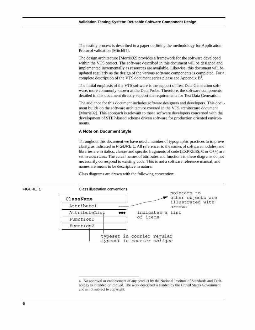
Throughout this document we have used a number of typographic practices to improveclarity, as indicated in FIGURE 1. All references to the names of software modules, andlibraries are in italics, classes and specific fragments of code (EXPRESS, C or C++) areset in courier. The actual names of attributes and functions in these diagrams do notnecessarily correspond to existing code. This is not a software reference manual, andnames are meant to be descriptive in nature.
Class diagrams are drawn with the following convention:
FIGURE 1 Class illustration conventions
4. No approval or endorsement of any product by the National Institute of Standards and Tech-nology is intended or implied. The work described is funded by the United States Governmentand is not subject to copyright.
ClassName
Attribute1
AttributeList
Function1
Function2
pointers toother objects areillustrated witharrows
●●● indicates a listof items
typeset in courier regulartypeset in courier oblique
Overview
7
2 Overview
The VTS software architecture integrates modular software libraries. These librarieswill be incorporated into a single system which supports functions needed for the vali-dation process [Mitch91]. The use of object-oriented techniques and standard interfaceswill enable software reusability. The system will use software as available from externalsources. When such software is unavailable, the necessary software will be developed.Support for the implementation methods specific to STEP will need to be developed.
Since STEP is a developing standard, the mechanisms for its implementation are notstabilized. Furthermore, since these mechanisms are developing concurrently with theapplication models which the VTS software is used to validate, it is unlikely that exter-nally developed software will be available in the necessary time frame. These mecha-nisms include the specification language for the application models -- EXPRESS[ISO11] -- and the data interface formats, such as the exchange file format [ISO21]. TheVTS must be responsive to changes in these implementation mechanisms by providingsoftware which is quickly and easily adaptable to new versions of the mechanisms.
The following goals have influenced the design of the VTS software architecture:
■ minimize the impact of changes to the standard on implementation software
■ permit easy transition of the software to support a new application model,
■ minimize the need for data translation by providing an integrated system which sup-ports a broad range of functions,
■ provide a single end-user program,
■ enable the development of different style user interfaces,
■ allow for the integration of externally developed software into the system, and
■ develop reusable software.
All the software components needed to support the testing process involve the comput-erized manipulation of data based on a common schema or application model. There-fore, the approach taken has been to develop a library of data structures and accessfunctions for representing a schema which can be shared among the different compo-nents. These data structures must be rich enough to store data and provide somesemantic information from the application models at runtime. Semantic informationneeded at runtime includes the names of the structures, their fields, and, when possible,acceptable values for the fields and rules governing instance structure. In the initialimplementation the latter information is available only by displaying the applicationmodel, as specified in EXPRESS, to the user.
Relationships between the VTS Software Components
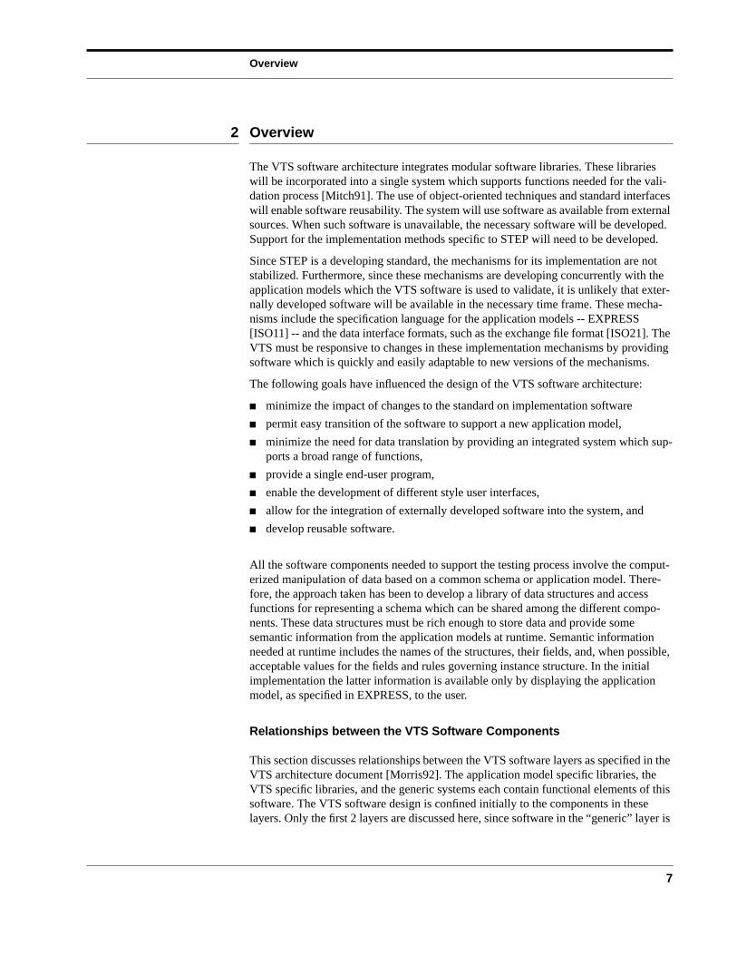
This section discusses relationships between the VTS software layers as specified in theVTS architecture document [Morris92]. The application model specific libraries, theVTS specific libraries, and the generic systems each contain functional elements of thissoftware. The VTS software design is confined initially to the components in theselayers. Only the first 2 layers are discussed here, since software in the “generic” layer is
Validation Testing System: Reusable Software Component Design
8
expected to come from outside (i.e. commercial or public domain) sources. Dependen-cies between the software in these layers are shown in FIGURE 2.
FIGURE 2 VTS Software Component Relationships
The division of the VTS software into component libraries enables code reuse by encap-sulating the functionality needed for different aspects of the validation process. Severalconsiderations are influential in defining the components of the VTS software, but twofunctional requirements are of particular importance:
Schema
Indicates Dependency
DatabaseUtilities
Translators
ApplicationDatabase
Library
GenericInterfaces
AbstractData Types
Data Probe
STEP Class
VTSInterface
Data Editor EXPRESSBrowser
Application
VTS
Generic
SpecificLibraries
ModelSpecific
Libraries
andMachine
DependentSystems
Generated Library
Library
LEGEND:
VTS Specific / Model Independent Layer
9
■ the need to easily transition the software to a new application model, and
■ the desire to enable different user interfaces to be developed.
The conceptual division of VTS software is based on these requirements. The informa-tion from a particular application model is encapsulated in the Schema Class Library.The Data Editor Library encapsulates the information and operations needed for manip-ulating and editing that information. The VTS Interface Library contains the operationsneeded to present that information to the user. The presentation format in the user inter-face is not influenced by the specific content of the information but uses generalizations,or abstractions, about the structure of the information. These abstractions are based onEXPRESS and are supported by the STEP Class Library.
The VTS architecture layering supports modularization of the software. Componentlibraries in each layer are dependent on some of the libraries in the next, more generallayer. However, the more general layers are not dependent on the less general layers.For example, the VTS specific layer depends on the generic systems layer, but not viceversa. Dependencies are limited to the interface between layers. The exception is in thedatabase management system. The database system will come from an external sourceand will have its own particular structure.
The VTS architecture is structured to enable reuse of the software. A different style ofuser interface could be developed for the VTS software by replacing the VTS InterfaceLibrary. This can be done without affecting the data editing and representation capabili-ties of the system. For example, two different systems could be developed by replacingthis library. One could support window-based interfaces and the other ASCII-basedinterfaces. These systems would provide the same functions in terms of editing andrepresentational capabilities, since those components of the software would not change.
Other programs may use parts of the VTS software. In particular, the STEP ClassLibrary and Schema Class libraries may represent the application data structures. Stand-alone translators could be developed using these libraries. These translators would notbe dependent on the VTS Interface Library which may require a sophisticatedwindowing system. But they would share the same data representation capabilities ofthe VTS software and would be able to directly access the same database using theinterface provided in the Schema Class Library. The interface to the database would betransparent to the translators. Likewise, parts of the VTS Interface and Data Editorlibraries could be used for any general purpose editor of highly structured information.
3 VTS Specific / Model Independent Layer
Software in this layer is specific to the needs of validation testing but independent ofany particular application model. These include the data structures needed to represententities. In addition, the functionality for editing the data contained in these data struc-tures is in this layer.
3.1 STEP Class Library
The STEP Class Library (SCL) is a collection of application independent class defini-tions. They are used by the application dependent classes found in the Schema ClassLibrary. Classes found in the SCL include a common “base” class for all entity class
Validation Testing System: Reusable Software Component Design
10
definitions and classes to maintain meta-information from the schemas. After a briefdescription of some problems solved by the SCL, this section will conclude with defini-tions of the major classes in this library.
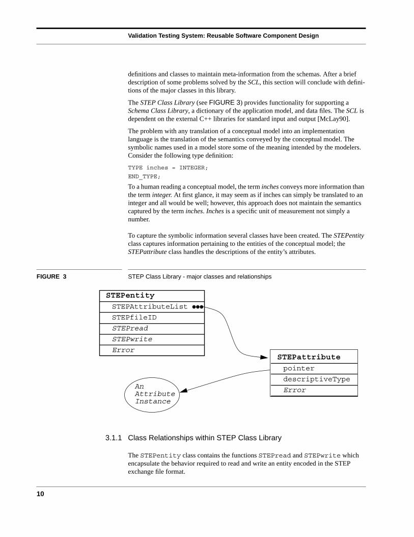
The STEP Class Library (see FIGURE 3) provides functionality for supporting aSchema Class Library, a dictionary of the application model, and data files. The SCL isdependent on the external C++ libraries for standard input and output [McLay90].
The problem with any translation of a conceptual model into an implementationlanguage is the translation of the semantics conveyed by the conceptual model. Thesymbolic names used in a model store some of the meaning intended by the modelers.Consider the following type definition:
TYPE inches = INTEGER;
END_TYPE;
To a human reading a conceptual model, the term inches conveys more information thanthe term integer. At first glance, it may seem as if inches can simply be translated to aninteger and all would be well; however, this approach does not maintain the semanticscaptured by the term inches. Inches is a specific unit of measurement not simply anumber.
To capture the symbolic information several classes have been created. The STEPentityclass captures information pertaining to the entities of the conceptual model; theSTEPattribute class handles the descriptions of the entity’s attributes.
FIGURE 3 STEP Class Library - major classes and relationships
3.1.1 Class Relationships within STEP Class Library
The STEPentity class contains the functions STEPread and STEPwrite whichencapsulate the behavior required to read and write an entity encoded in the STEPexchange file format.
STEPattribute
pointer
descriptiveType
Error
STEPentity
STEPAttributeList
STEPfileID
STEPread
STEPwrite
Error
AnAttributeInstance
●●●
VTS Specific / Model Independent Layer
11
The STEPattributeList is a list of pointers to the instances of the attributes of anentity. Functions can traverse the list of attributes without any knowledge of attributetypes. Information in the STEPattribute class describes the type of an attribute fora given instance of the attribute. Using this information the STEPattribute can“validate” itself by ensuring that the data pointed to by the STEPattribute corre-sponds to the correct type.
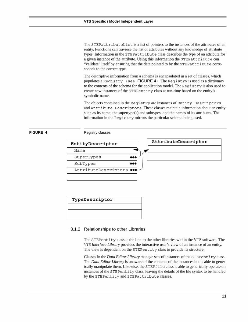
The descriptive information from a schema is encapsulated in a set of classes, whichpopulates a Registry (see FIGURE 4). The Registry is used as a dictionaryto the contents of the schema for the application model. The Registry is also used tocreate new instances of the STEPentity class at run-time based on the entity’ssymbolic name.
The objects contained in the Registry are instances of Entity Descriptorsand Attribute Descriptors. These classes maintain information about an entitysuch as its name, the supertype(s) and subtypes, and the names of its attributes. Theinformation in the Registry mirrors the particular schema being used.
FIGURE 4 Registry classes
3.1.2 Relationships to other Libraries
The STEPentity class is the link to the other libraries within the VTS software. TheVTS Interface Library provides the interactive user’s view of an instance of an entity.The view is dependent on the STEPentity class to provide its structure.
Classes in the Data Editor Library manage sets of instances of the STEPentity class.The Data Editor Library is unaware of the contents of the instances but is able to gener-ically manipulate them. Likewise, the STEPfile class is able to generically operate oninstances of the STEPentity class, leaving the details of the file syntax to be handledby the STEPentity and STEPattribute classes.
AttributeDescriptorEntityDescriptor
Name
SuperTypes
SubTypes
AttributeDescriptors
TypeDescriptor
●●●
●●●
●●●
Validation Testing System: Reusable Software Component Design
12
The Registry is used by the Data Editor Library. The Registry provides func-tions for inserting, deleting, and retrieving entity descriptors. All of the entity descrip-tors in the Registry must be unique. To support this functionality the nodes in theRegistry have a key. In EXPRESS a unique key is determined by the combination ofthe entity name and schema name, but in this implementation uniqueness is determinedby entity name alone. Entity names may not be used in more than one schema.
3.1.3 Classes
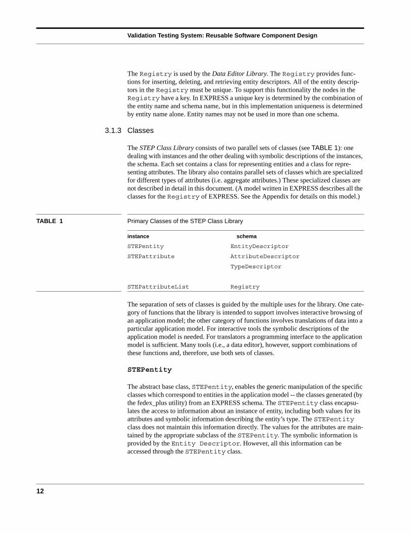
The STEP Class Library consists of two parallel sets of classes (see TABLE 1): onedealing with instances and the other dealing with symbolic descriptions of the instances,the schema. Each set contains a class for representing entities and a class for repre-senting attributes. The library also contains parallel sets of classes which are specializedfor different types of attributes (i.e. aggregate attributes.) These specialized classes arenot described in detail in this document. (A model written in EXPRESS describes all theclasses for the Registry of EXPRESS. See the Appendix for details on this model.)
TABLE 1 Primary Classes of the STEP Class Library
instance schema
STEPentity EntityDescriptor
STEPattribute AttributeDescriptor
TypeDescriptor
STEPattributeList Registry
The separation of sets of classes is guided by the multiple uses for the library. One cate-gory of functions that the library is intended to support involves interactive browsing ofan application model; the other category of functions involves translations of data into aparticular application model. For interactive tools the symbolic descriptions of theapplication model is needed. For translators a programming interface to the applicationmodel is sufficient. Many tools (i.e., a data editor), however, support combinations ofthese functions and, therefore, use both sets of classes.
STEPentity
The abstract base class, STEPentity, enables the generic manipulation of the specificclasses which correspond to entities in the application model -- the classes generated (bythe fedex_plus utility) from an EXPRESS schema. The STEPentity class encapsu-lates the access to information about an instance of entity, including both values for itsattributes and symbolic information describing the entity’s type. The STEPentityclass does not maintain this information directly. The values for the attributes are main-tained by the appropriate subclass of the STEPentity. The symbolic information isprovided by the Entity Descriptor. However, all this information can beaccessed through the STEPentity class.
VTS Specific / Model Independent Layer
13
In addition, the STEPentity class provides the necessary functions for implementingthe STEP file exchange protocol [ISO21] and initiating instance validation. In partic-ular, the STEPentity class contains an instance identifier, error state information, anda list of its attributes. The identifier is used to maintain the instances’s identifier for anexchange file. The error state is used to report invalid or missing data values. As the ISOstandard develops, the STEPentity class may be used in the implementation of otherdata sharing features such as an identifier which has a broader context than an exchangefile.
A key design goal for the SCL was to isolate the implementation of the exchange proto-col from the generated class definitions for a particular application model. By doing so,it is possible to change the exchange protocol without modifying code that uses theSchema Class Library. This approach also serves to isolate the details of the exchangeprotocol from the users of the software.
The exchange file has a syntactic format based on an EXPRESS schema. The file is aseries of sets of data values. The format of the data sets is based directly on the entitydefinitions of the corresponding application model. The fragment below shows anexample of the file exchange format. The numbers preceded by the symbol @ areinstance identifiers. The following fragment is from a STEP exchange file based on theGeometry model [ISO42] (this example is from a very early version of the file format):
STEP;
HEADER;
FILE_IDENTIFICATION(’IBMPRT2’,’1990 01 24 18 3017’,(’L.MCKEE’),(’COMPANY 3’),’1’,’1’,’PDES’);
FILE_DESCRIPTION(’SIMPLE PART’);
IMP_LEVEL(’USER DEFINED ENTITIES ONLY’);
ENDSEC;
DATA;
.
.
@19=DIRECTION(,,0.7071067845031212,0.7071067845031212,0.);
@20=DIRECTION(,,-0.7071067845031212,0.7071067845031212,0.);
@21=DIRECTION(,,0.,0.,1.0000000308363815);
@22=CARTESIAN_POINT(,,0.0625,21.3794994354248047,11.5299997329711914);
@23=TRANSFORMATION(,,#19,#20,#21,#22,);
@24=COORDINATE_SYSTEM(,,,#23);
STEPattribute
Like the STEPentity class the STEPattribute class encapsulates the access toinformation about values for an entity’s attributes and symbolic information describingthe attribute. The actual values for an entity’s attributes are maintained by the appro-priate class in the Schema Library; however, the STEPattribute class maintains apointer to the value for an attribute. This feature is used to access an attribute’s valueswithout knowing the nature of the attribute. The descriptive information about theattribute is maintained within the AttributeDescriptor which is accessible
Validation Testing System: Reusable Software Component Design
14
through the instance of the STEPattribute. The STEPattribute class maintainserror state information for the attribute. The error state is accessed by the STEPentityclass during instance validation.
STEPattributeList
The STEPattributeList class is the key to providing common functionality forsubclasses of the STEPentity class. The list can be used to traverse the attributes ofany entity instance. Using the instances of the STEPattribute both the values forand the descriptive information about the attribute can be accessed. For example, the listis traversed by the function which implements the exchange file format for reading andwriting of the values for an instance. Similarly, the list is used to display the names of anentity’s attributes to an interactive user.
Registry
The purpose of the Registry is to provide access to the descriptive information aboutschemas, types and attributes. This information is used to present meaningful informa-tion, such as names, to users. In addition the Registry has a mechanism for thecreation of instances based on the entity name. The traversal of the schema hierarchy viapointers to the parent and subtype entities is also facilitated by information in theRegistry.
A Registry provides two important functions:
■ it contains symbolic information about the structures (the entities and theirattributes) described in the application model.
■ it provides a mechanism to create new instances of an entity type given an entity’ssymbolic name.
The Registry used in the VTS software contains entries associated with an applica-tion model written in EXPRESS; however, the Registry class may alternatively bepopulated with information from models specified in a different data modelinglanguage. To use the Registry for a different data modeling language, appropriatedescriptor classes (analogous to the Entity and Attribute Descriptors described below)must be defined as subtypes of the Registry Entry class.
Support for multiple schemas at runtime is one requirement which led to the design ofthe Registry class. The Registry class provides a mechanism to instantiate aprogram with a particular application model. In the design of the initial VTS softwareonly one application model, and therefore one instance of a Registry, will be used.However, it is envisioned that multiple registries would be used to support multipleschemas in a single program. By doing so the user would be able to switch “contexts.”In this way the application model visible to the user could be switched at runtime.
An aspect of the STEP application models, currently not addressed in the VTS softwaredesign, relates to the organization of the application models. The VTS softwarecurrently is not addressing these requirements because the organization of these modelsand the relationship of this organization to the EXPRESS language is in a very activestage of development. It is anticipated that a mechanism for supporting multiple, andpossibly overlapping or nested, application models in a single program will be needed to
VTS Specific / Model Independent Layer
15
support the emerging organization. As these requirements are defined and become morestable, more support for these will need to be incorporated into the VTS softwaredesign. The Registry class encapsulates the mechanism to support future applicationmodel needs. This encapsulation will isolate the changes to the VTS software needed tosupport the new organization.
One problem area is entity referencing between schemas. Two EXPRESS languageconstructs in the interface specification portion of EXPRESS, USE FROM andREFERENCE FROM, allows schemas to use entities from other schemas. This is nothandled in a robust way by the current version of fedex_plus [McLay 90] or the VTSlibraries. This area is in flux in the EXPRESS committee and other committees withinthe STEP community.
As an aside, the class descriptors used by the Registry were developed by using anearly version of the Data Probe (see the section Data Probe: An Example Application).A model of EXPRESS in EXPRESS was created, translated to C++ and a Data Probe ofthis EXPRESS of EXPRESS schema was created. Data entered in this particular DataProbe was used to prototype the class information which we desired to represent in theRegistry. This iterative design process has proven quite useful [Kramer92].
EntityDescriptor
For each entity in the application model an entity descriptor is created. An entitydescriptor encapsulates the minimum set of symbolic information needed by the VTSsoftware at runtime. The entity descriptor is represented by the class EntityDe-scriptor. This class is used to populate an instance of the Registry class and isthe Registry entry for an EXPRESS information model. Instances of this classcontain the following information:
■ name
■ schema
■ subtype(s)
■ supertype(s)
■ attribute(s)
■ creation function
One entity descriptor is created for each entity in the application model. The entitydescriptor is accessible in a number of ways.
■ The entity descriptor is represented as a global variable in the Schema library.
■ Those subclasses of the STEPentity class which are instantiated contain a pointerto an EntityDescriptor. Each instance of a STEPentity points to the entitydescriptor for the entity type.
■ When an entity descriptor is stored in a Registry, it is accessible from the Reg-istry given the entity name. The entity name serves as the key into the Regis-try.
Validation Testing System: Reusable Software Component Design
16
AttributeDescriptor
A description of each attribute is also contained in the schema dictionary orRegistry. These descriptions are most easily accessible through the entity descrip-tions which contain direct pointers to the descriptions of the attributes. The EXPRESSdefinition of the attribute descriptor is as follows:
ENTITY attribute_descriptor;
name: STRING;
type: type_descriptor;
optionality: BOOLEAN;
uniqueness: BOOLEAN;
owner: entity_descriptor;
END_ENTITY;
This structure describes the basic properties associated with an attribute. In the initialimplementation this information is used to present a simple description of the attributeto the user; in later implementations it may be used in conjunction with constraintchecking on values of attributes.
The initial implementation of the VTS software does not provide support for derivedattributes. The requirements which support derived attributes have not been identifiedfor this design. However, it is anticipated that the AttributeDescriptor conceptwill be extended to support these attributes.
TypeDescriptor
Much of the information which describes an attribute is contained in the attribute’s type.To support this, another type of entity is introduced: the type_descriptor. Due tothe variety of types available in an EXPRESS schema, there are several subtypes oftype_descriptor. The following EXPRESS definitions represent the basictype_descriptor:
TYPE base_type =
ENUMERATION OF (
INTEGER_TYPE, STRING_TYPE, REAL_TYPE, ENTITY_TYPE,AGGREGATE_TYPE, ENUM_TYPE, REAL_PTR_TYPE, INTEGER_PTR_TYPE,SELECT_TYPE, BOOLEAN_TYPE, LOGICAL_TYPE, NUMBER_TYPE,BINARY_TYPEUNKNOWN_TYPE );
END_TYPE;
ENTITY type_descriptor;
name: STRING ;
fundamental_type: base_type;
description: STRING;
END_ENTITY;
The name, fundamental_type and description are currently implemented inthe VTS software. The subtypes of the type_descriptor are not implemented inthe initial implementation of the VTS software. The level of detail provided by thisdesign is not a priority for the VTS software. The information encapsulated in thetype_descriptor represents a minimal set of information which is needed atruntime.
VTS Specific / Model Independent Layer
17
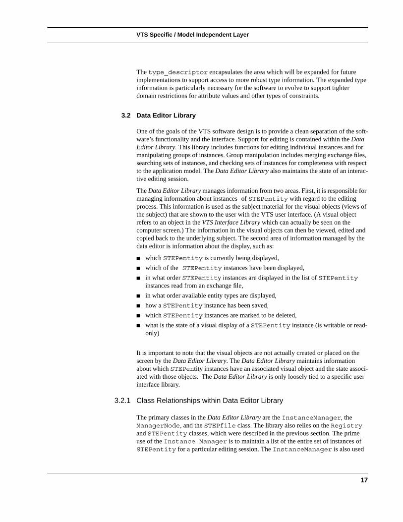
The type_descriptor encapsulates the area which will be expanded for futureimplementations to support access to more robust type information. The expanded typeinformation is particularly necessary for the software to evolve to support tighterdomain restrictions for attribute values and other types of constraints.
3.2 Data Editor Library
One of the goals of the VTS software design is to provide a clean separation of the soft-ware’s functionality and the interface. Support for editing is contained within the DataEditor Library. This library includes functions for editing individual instances and formanipulating groups of instances. Group manipulation includes merging exchange files,searching sets of instances, and checking sets of instances for completeness with respectto the application model. The Data Editor Library also maintains the state of an interac-tive editing session.
The Data Editor Library manages information from two areas. First, it is responsible formanaging information about instances of STEPentity with regard to the editingprocess. This information is used as the subject material for the visual objects (views ofthe subject) that are shown to the user with the VTS user interface. (A visual objectrefers to an object in the VTS Interface Library which can actually be seen on thecomputer screen.) The information in the visual objects can then be viewed, edited andcopied back to the underlying subject. The second area of information managed by thedata editor is information about the display, such as:
■ which STEPentity is currently being displayed,
■ which of the STEPentity instances have been displayed,
■ in what order STEPentity instances are displayed in the list of STEPentityinstances read from an exchange file,
■ in what order available entity types are displayed,
■ how a STEPentity instance has been saved,
■ which STEPentity instances are marked to be deleted,
■ what is the state of a visual display of a STEPentity instance (is writable or read-only)
It is important to note that the visual objects are not actually created or placed on thescreen by the Data Editor Library. The Data Editor Library maintains informationabout which STEPentity instances have an associated visual object and the state associ-ated with those objects. The Data Editor Library is only loosely tied to a specific userinterface library.
3.2.1 Class Relationships within Data Editor Library
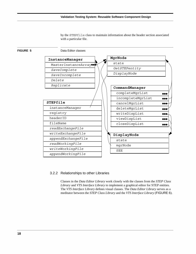
The primary classes in the Data Editor Library are the InstanceManager, theManagerNode, and the STEPfile class. The library also relies on the Registryand STEPentity classes, which were described in the previous section. The primeuse of the Instance Manager is to maintain a list of the entire set of instances ofSTEPentity for a particular editing session. The InstanceManager is also used
Validation Testing System: Reusable Software Component Design
18
by the STEPfile class to maintain information about the header section associatedwith a particular file.
FIGURE 5 Data Editor classes
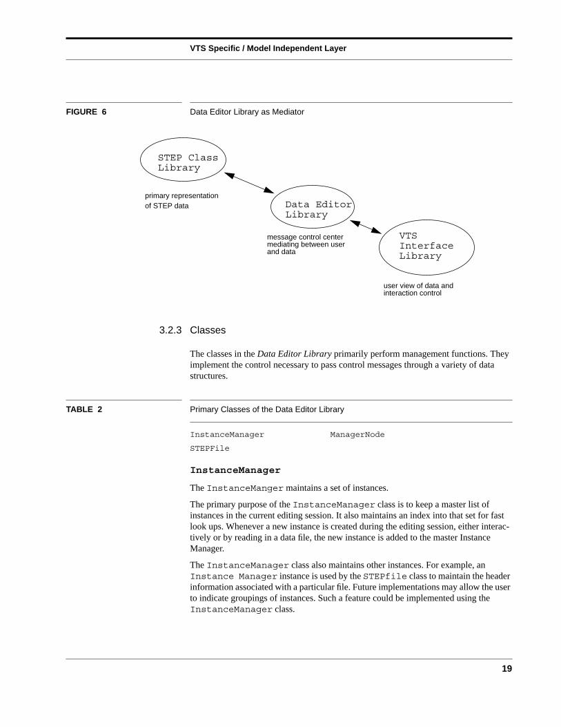
3.2.2 Relationships to other Libraries
Classes in the Data Editor Library work closely with the classes from the STEP ClassLibrary and VTS Interface Library to implement a graphical editor for STEP entities.The VTS Interface Library defines visual classes. The Data Editor Library serves as ameditator between the STEP Class Library and the VTS Interface Library (FIGURE 6).
MgrNode
state
GetSTEPentity
DisplayNode
InstanceManager
MasterInstanceArray
SaveComplete
SaveIncomplete
Delete
Replicate
STEPfile
instanceManager
registry
headerID
fileName
readExchangeFile
writeExchangeFile
appendExchangeFile
readWorkingFile
writeWorkingFile
appendWorkingFile
●●●
DisplayNode
state
mgrNode
SEE
CommandManager
completeMgrList
incompleteMgrList
cancelMgrList
deleteMgrList
writeDispList
viewDispList
closeDispList
●●●
●●●
●●●
●●●
●●●
●●●
●●●
VTS Specific / Model Independent Layer
19
FIGURE 6 Data Editor Library as Mediator
3.2.3 Classes
The classes in the Data Editor Library primarily perform management functions. Theyimplement the control necessary to pass control messages through a variety of datastructures.
TABLE 2 Primary Classes of the Data Editor Library
InstanceManager ManagerNode
STEPFile
InstanceManager
The InstanceManger maintains a set of instances.
The primary purpose of the InstanceManager class is to keep a master list ofinstances in the current editing session. It also maintains an index into that set for fastlook ups. Whenever a new instance is created during the editing session, either interac-tively or by reading in a data file, the new instance is added to the master InstanceManager.
The InstanceManager class also maintains other instances. For example, anInstance Manager instance is used by the STEPfile class to maintain the headerinformation associated with a particular file. Future implementations may allow the userto indicate groupings of instances. Such a feature could be implemented using theInstanceManager class.
Data Editor
STEP Class
VTSInterface
primary representationof STEP data
message control centermediating between userand data
user view of data andinteraction control
Library
Library
Library
Validation Testing System: Reusable Software Component Design
20
ManagerNode (MgrNode)
The ManagerNode class maintains an association between an object of the STEPEn-tity class and a visual object in the user interface. The ManagerNode class allowsthe application model to remain independent of the VTS Interface Library. TheManagerNode maintains an editing state for a STEPentity object and a state forthe display object. The editing states are
■ saved complete,
■ saved incomplete,
■ marked for deletion, and
■ new
The saved complete state indicates that the instance has all necessary values (i.e. allnon-optional attributes have values) and, as far as can be determined, these values arecorrect. The saved incomplete indicates that the instance does not have all its necessaryvalues. This state can be set in two ways: 1) An error resulted when the validation func-tion from the STEPentity class was executed. 2) Or the user interactively set the stateto “incomplete” through the user interface. The new state indicates that the instance hasbeen recently created interactively and has not been edited.
The Manager Node maintains information about which instances have correspondingDisplay objects and the state of those Display objects. Available states for Displayobjects are
■ editable display object
■ view-only display object
■ unmapped display object
■ no display object
An editable display object is visible on the screen and may be edited by a user. A view-only display object is visible on the screen but may only be viewed by the user. Anunmapped display object refers to a display object which has been created but is notcurrently visible on the screen. (An Unmapped display object is a mechanism for buff-ering the implementation of the display.)
In addition, the Manager Node also maintains intended states for the instances. Intendedstates are used to mark instances for attempted state changes which can then be appliedat one time. For example, several instances can be marked for deletion or display, andmessages to initiate the appropriate operations can be sent to the respective objects atone time. This functionality is intended to aid editing across the Internet or modemswhere display performance is a problem.
STEPFile
The STEPFile class implements two important functions:
■ controls the reading and writing of data files, and
■ interfaces with the file system for opening and closing files.
VTS Specific / Model Independent Layer
21
The STEPfile class relies on the STEPentity, the Registry, and the InstanceManager classes for implementing the functions which it initiates.
For instance, for the reading and writing of data files the STEPfile class serves as adriver. The STEPfile class opens the file, controls the parsing of the sections of thefile, initiates the creation of new STEPentity instances (the Registry class actu-ally creates the instances), initiates the reading or writing of the instances (theSTEPentity class actually parses the instances), updates the InstanceManagerduring the process, and finally closes the file. The parsing of the file involves two passesover the Data Section (to resolve forward references.) These passes are controlled by theSTEPfile class. Throughout the process the STEPfile class monitors the error stateand provides appropriate messages as errors are encountered.
The STEPfile class also implements functions to save the working state of an editingsession. The state of the session is saved into a file similar in structure to an exchangefile: a working session file. The working session file stores the state of the instances withthe editing session as indicated by the ManagerNode. Unlike the exchange file, theworking session file does not require STEPentity instances to be a complete andvalid state (in other words, attribute values, required by the application model, can bemissing).
CommandManager
The CommandManager isolates and encapsulates editing functionality. Functionallythe command manager contains commands which act upon the selected entities. Forexample, a set of entities which are to be saved in a complete state are maintained by theCommand Manager. Other operations handled by the CommandManager includesave incomplete, cancel, and delete. These commands are subsequently processed bythe Probe class (defined in the VTS Interface Library, see FIGURE 7).
DisplayNode
The DisplayNode is the class which contains display information for an entity. TheDisplayNode encapsulates all display information. Furthermore DisplayNodesonly exist for those entities which are actually displayed on the screen. This is a signifi-cant performance issue as we expect to have data files with thousands of entities. Thedisplay node points to the actual display object which could be replaced by other displayobjects in the future if a new user interface is chosen.
3.3 VTS Interface Library
The VTS Interface Library was designed with the user in mind. Users are expected to bepeople familiar with the STEP file format [ISO 21], and the EXPRESS language [ISO11]. Users interact primarily with three different types of windows. First the EntityTypewindow (see FIGURE 10) which displays a list of all entity types for the schema. Theother window is the Entity Instance window (see FIGURE 11) which displays entityinstances. Display of these instances is in the STEP physical file format, a formatfamiliar to the users. The third window type is the STEP Entity Editor (SEE) windowused for the actual editing of data.
Validation Testing System: Reusable Software Component Design
22
Each time the user creates a new instance or views an existing one a SEE window (seeleft side window of FIGURE 10) is created and displayed. In the context of the currentimplementation which uses the X windows system each SEE is created as a separatewindow which can be moved and iconified. This approach allows the user to interactwith the windows without introducing any new unknown window managementcommands.
Where possible the key bindings used by the display and editable objects match thosefound in GNU emacs [Schoo92]. This library works with a window manager for the Xwindow system environment. Windows inserted onto the screen will generally be deco-rated and placed by the window manager. Moving and resizing of windows will be donewith the aid of the window manager.
3.3.1 Class Relationships within Library
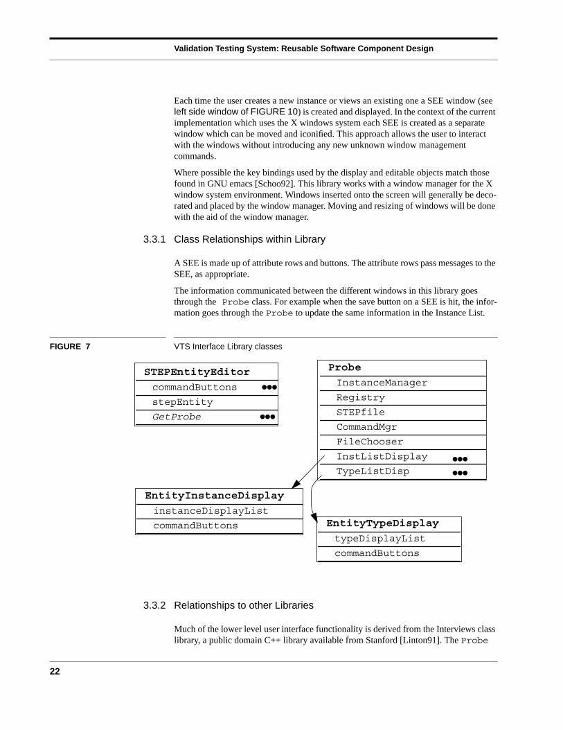
A SEE is made up of attribute rows and buttons. The attribute rows pass messages to theSEE, as appropriate.
The information communicated between the different windows in this library goesthrough the Probe class. For example when the save button on a SEE is hit, the infor-mation goes through the Probe to update the same information in the Instance List.
FIGURE 7 VTS Interface Library classes
3.3.2 Relationships to other Libraries
Much of the lower level user interface functionality is derived from the Interviews classlibrary, a public domain C++ library available from Stanford [Linton91]. The Probe
Probe
InstanceManager
Registry
STEPfile
CommandMgr
FileChooser
InstListDisplay
TypeListDisp
STEPEntityEditor
commandButtons
stepEntity
GetProbe
EntityInstanceDisplay
instanceDisplayList
commandButtons
●●●
EntityTypeDisplay
typeDisplayList
commandButtons
●●●
●●●
●●●
VTS Specific / Model Independent Layer
23
class manages the interaction with the data objects managed by classes of otherlibraries. The Probe class manages the interaction between the displays. Its main func-tion is to manage the display information and to keep it consistent with the underlyinginformation objects. (The same information in different windows is kept consistent.)
The Probe receives an interpretation of keystroke or button commands and performsthe function. For example, to save the instances, the Probe receives the list ofcommands to execute from the CommandManager (in the Data Editor Library).
When a button is pushed the Probe executes a single command for the selectedinstance and is “notified” by the generic Interview class Subject when it is set by thebutton object.
In general, display objects such as those in the SEE point to the actual informationobjects instantiated from other classes such as the STEP Class Library. The SEE itselfpoints to an instance of a STEPentity (from the STEP Class Library). A particularrow of a SEE which displays the attribute information for a particular entity points to aparticular attribute and an instance of the class STEPattribute (also from the STEPClass Library).
3.3.3 Classes
The classes in the VTS Interface Library group the functionality of existing Interviewslibrary classes into a meaningful interface.
TABLE 3 Primary Classes of the VTS User Interface Library
StepEntityEditor (SEE) Probe
EntityInstanceList EntityTypeList
StepEntityEditor (SEE)
The StepEntityEditor is a visual representation of an underlying STEPentity.The SEE allows a user to interactively edit a STEPentity on the screen. TheStepEntityEditor class is independent of the particular STEPentity type. TheSEE sizes itself appropriately based on the number of STEPattributes contained inthe underlying STEPentity. When the user is editing through a SEE, the current rowcorresponds to an attribute of the underlying entity.
SEE windows are created and appear when a command for creating or editing an entityinstance is given. They disappear (unless “pinned”) when a command is given to savethe instance, delete the instance, or close the window. A single SEE window is shown inFIGURE 8.
Validation Testing System: Reusable Software Component Design
24
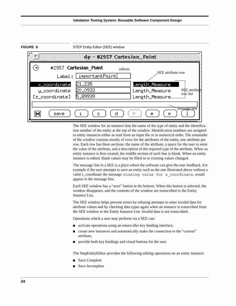
FIGURE 8 STEP Entity Editor (SEE) window
The SEE window for an instance lists the name of the type of entity and the identifica-tion number of the entity at the top of the window. Identification numbers are assignedto entity instances either as read from an input file or in numerical order. The remainderof the window consists mostly of rows for the attributes of the entity, one attribute perrow. Each row has three sections: the name of the attribute, a space for the user to enterthe value of the attribute, and a description of the required type of the attribute. When anentity instance is first created, the middle section of each line is blank. When an entityinstance is edited, blank values may be filled in or existing values changed.
The message line in a SEE is a place where the software can give the user feedback. Forexample if the user attempts to save an entity such as the one illustrated above without avalid x_coordinate the message: missing value for x_coordinate, wouldappear in the message line.
Each SEE window has a “save” button at the bottom. When this button is selected, thewindow disappears, and the contents of the window are transcribed to the EntityInstance List.
The SEE window helps prevent errors by refusing attempts to enter invalid data forattribute values and by checking data types again when an instance is transcribed fromthe SEE window to the Entity Instance List. Invalid data is not transcribed.
Operations which a user may perform via a SEE can:
■ activate operations using an emacs-like key binding interface,
■ create new instances and automatically make the connection to the “current”attribute,
■ provide both key bindings and visual buttons for the user.
The StepEntityEditor provides the following editing operations on an entity instance:
■ Save Complete
■ Save Incomplete
SEE attribute row
SEE attribute
editors
row list
message line
Application Model Specific Layer
25
■ Cancel
■ Delete
■ Replicate
■ Edit Attribute’s Instance
■ Mark (select marked instance for current attribute)
■ List Values (for an enumeration)
EntityInstanceListDisplay
The EntityInstanceListDisplay class is a display object. It contains an objectwhich is a list of string representations of the actual underlying data entities. This scrol-lable list is the primary user interface mechanism for selecting particular entities. It alsocontains a collection of buttons which the user can use to perform operations on theunderlying entities. From the user interface, the user can mark an entire set of instances,delete or save, and invoke these operations at once via an execute button (or keystroke).Another field allows the user to search for particular entities by entering a substring.
EntityTypeListDisplay
The EntityTypeDisplayList has many of the same functional mechanisms asthe EntityInstanceDisplayList. It presents the user with a list of types whichthe user may select. The user may elect to create a new instance of the selected type ordisplay more semantic information about the type. This window also contains asearching function.
Probe
The Probe is the main grouping object. It contains pointers to the InstanceMan-ager, Registry, STEPfile, Command Manager, FileChooser,InstListDisplay, TypeListDisp. It also has a number of menu objects. In asense the Probe object is the object oriented equivalent of a main routine in a Cprogram.
4 Application Model Specific Layer
The application model specific layer represents the components which are tailored to theapplication model undergoing validation. These components are updated each time theapplication model changes.
The STEP Schema Class Library is the set of files that result from the translation of anEXPRESS schema. These files are generated automatically using the Fed-X Toolkit[Clark92] for translating EXPRESS and are producible from an EXPRESS schema. Theprogram fedex_plus, which is a backend to Fed-X, takes a conceptual data model writtenin EXPRESS as input and generates three C++ files for each schema [Morris92]. TheC++ code in these files provides the class definitions and member functions for STEPentities needed by an application program.
Validation Testing System: Reusable Software Component Design
26
Applications in projects working on process planning research and an IGES to PDEStranslator have used the C++ code produced as the output of fedex_plus. The STEPSchema Class Library is the result of a mapping process between EXPRESS and C++.The mappings occur as follows:
■ EXPRESS entities are translated into C++ classes derived from the class STEPen-tity.
■ EXPRESS attributes are translated into data members.
■ Public access functions are automatically created allowing values to be read andwritten to the data members.
■ Instances of Entity and Attribute descriptors are created for populating a Regis-try.
5 Data Probe: An Example Application
The Data Probe is the major application which uses the various libraries described inthis document. It is intended to allow people involved with the creation and testing ofSTEP Application Protocols to examine and populate data files corresponding to thosemodels.
New versions of the Data Probe may be automatically generated for an EXPRESSschema. Each Data Probe executable is specific to a particular schema. A UNIX shellscript called mkprobe takes as input an EXPRESS schema and outputs a new DataProbe specific to that schema. The process of creating a new Data Probe is completelyautomated through this process. It is anticipated that users will not be working with verymany different schemas and will instead concentrate on one schema at a time.
FIGURE 10 shows the main windows of the Data Probe built for Part 42 of STEP. Theeditor consists of four types of persistent windows, all of which may be manipulated inthe typical ways (move, open, close, hide, expose, resize, etc.):
1 Data Probe management window (FIGURE 9),
2 STEP Entity Editor (SEE) windows (left side of FIGURE 10),
3 an Entity Type List window (right side of FIGURE 10),
4 and an Entity Instance List window (FIGURE 11).
Any number of temporary STEP Entity Editing (SEE) windows may be created anddestroyed as the editor is being used. A single SEE window is shown in the left side ofFIGURE 10, partly obscuring the Entity Type List window.
Data Probe Management Window
The Data Probe management window provides the user with systems functions such assaving or appending files, clearing the Entity Instance List, and quitting the editor. There
Data Probe: An Example Application
27
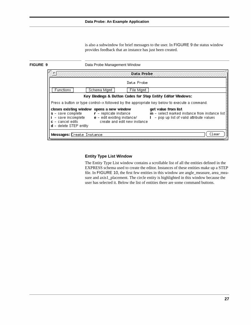
is also a subwindow for brief messages to the user. In FIGURE 9 the status windowprovides feedback that an instance has just been created.
FIGURE 9 Data Probe Management Window
Entity Type List Window
The Entity Type List window contains a scrollable list of all the entities defined in theEXPRESS schema used to create the editor. Instances of these entities make up a STEPfile. In FIGURE 10, the first few entities in this window are angle_measure, area_mea-sure and axis1_placement. The circle entity is highlighted in this window because theuser has selected it. Below the list of entities there are some command buttons.
Validation Testing System: Reusable Software Component Design
28
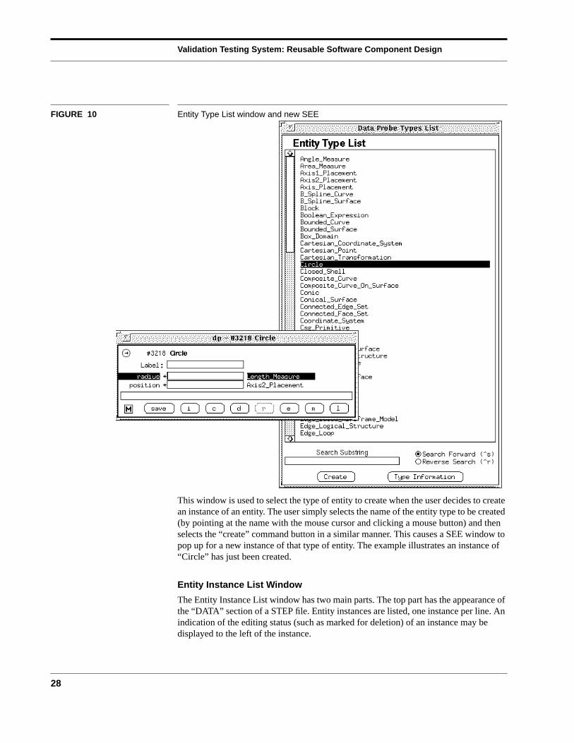
FIGURE 10 Entity Type List window and new SEE
This window is used to select the type of entity to create when the user decides to createan instance of an entity. The user simply selects the name of the entity type to be created(by pointing at the name with the mouse cursor and clicking a mouse button) and thenselects the “create” command button in a similar manner. This causes a SEE window topop up for a new instance of that type of entity. The example illustrates an instance of“Circle” has just been created.
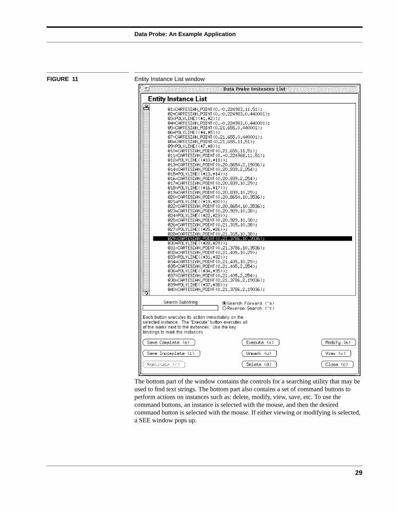
Entity Instance List Window
The Entity Instance List window has two main parts. The top part has the appearance ofthe “DATA” section of a STEP file. Entity instances are listed, one instance per line. Anindication of the editing status (such as marked for deletion) of an instance may bedisplayed to the left of the instance.
Data Probe: An Example Application
29
FIGURE 11 Entity Instance List window
The bottom part of the window contains the controls for a searching utility that may beused to find text strings. The bottom part also contains a set of command buttons toperform actions on instances such as: delete, modify, view, save, etc. To use thecommand buttons, an instance is selected with the mouse, and then the desiredcommand button is selected with the mouse. If either viewing or modifying is selected,a SEE window pops up.
Validation Testing System: Reusable Software Component Design
30
6 Conclusions, Summary and Future Directions
A functioning system called the Data Probe has been designed and implemented. At thetime of writing this document it is under preliminary testing by knowledgeable users.The implementation of a set of class libraries has proven to be a flexible and robustapproach. The libraries have been designed to allow the software developer the freedomto choose user interface styles and systems.
The initial implementation of the Data Probe is limited to the use of one input file at atime. The underlying data structures however will allow the use of multiple files and thisextension is planned for the future.
Future work will include a more sophisticated use of schemas with more display ofschema information and integration of a document browsing utility for on-line access tothe ISO documents. Another future activity is the move to an SDAI (STEP Data AccessInterface). SDAI will be a standard mechanism to access STEP data. As the standard isdefined data accessed with the Data Probe will move through an SDAI interface. Theintent is to use the same SDAI interface with persistence data repositories such as anobject oriented data base for the persistent storage of STEP data.
References
31
7 References
[Clark92] Clark, S.N., Libes, D., Fed-X: The NIST Express Translator, NISTIR4822, National Institute of Standards and Technology, Gaithersburg, MD,April 3, 1992.
[ISO11] ISO 10303 Industrial Automation Systems -- Product DataRepresentation and Exchange -- Part 11: Description Methods: TheEXPRESS Language Reference Manual, Draft International Standard,ISO TC184/SC4, Spiby, P., ed., July 15, 1992.
[ISO21] ISO 10303 Industrial Automation Systems -- Product DataRepresentation and Exchange -- Part 21: Clear Text Encoding of theExchange Structure, Draft International Standard, ISO TC184/SC4, VanMaanen, J., ed., July 15, 1992.
[ISO42] ISO 10303 Industrial Automation Systems -- Product Data Representationand Exchange -- Part 42: Integrated Generic Resources: Geometric andTopological Representation, Committee Draft N121.5 ISO TC184/SC4/WG4, Goult, R., ed., May 14, 1992.
[Kramer92] Kramer, T., Morris, K.C., Sauder, D. A Structural EXPRESS Editor,NISTIR 4903, National Institute of Standards and Technology,Gaithersburg, MD, July 1992.
[Linton91] Linton, M,. InterViews Reference Manual Version 3.0-alpha, ComputerSystems Laboratory, Departments of Electrical Engineering andComputer Science, Stanford University, Silicon Graphics, January 1991.
[McLay90] McLay, M.J., Morris, K.C., The NIST STEP Class Library, C++ at Work-’90 Conference Proceedings, (reprinted as NISTIR 4411,) September1990.
[Mitch91] Mitchell, M., A Proposed Testing Methodology for STEP ApplicationProtocol Validation, NISTIR 4684, National Institute of Standards andTechnology, Gaithersburg, MD, September 1991.
[Morris91] Morris, K.C., McLay, M., Carr, P. J., Validation Testing SystemRequirements, NISTIR 4676, National Institute of Standards andTechnology, Gaithersburg, MD, September 1991.
[Morris92] Morris, K.C., Architecture for the Validation Testing System Software ,NISTIR 4742, National Institute of Standards and Technology,Gaithersburg, MD, January 1992.
Validation Testing System: Reusable Software Component Design
32
[Schoo92] Schoonover, M., Bowie, J.S., Arnold, W., GNU Emacs UNIX TextEditing and Programming, Hewlett-Packard Press, 1992.
[Strang86] Strang, John, Programming with Curses, O’Reilly and Associates Inc.1986.
References
33
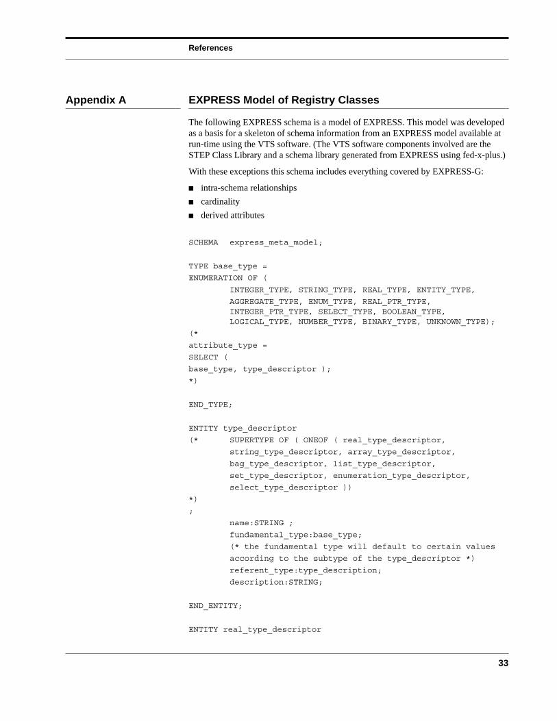
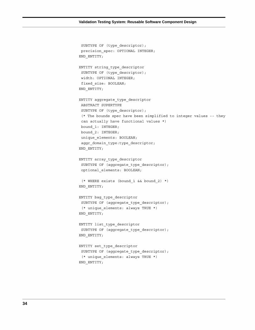
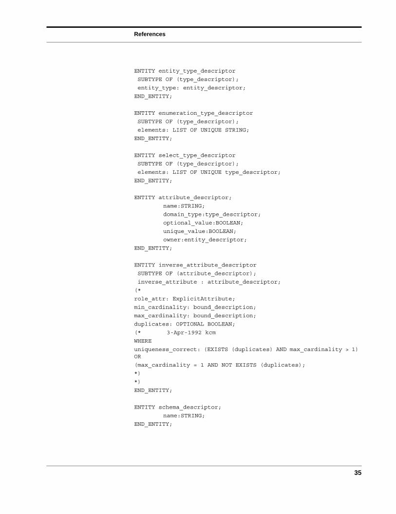
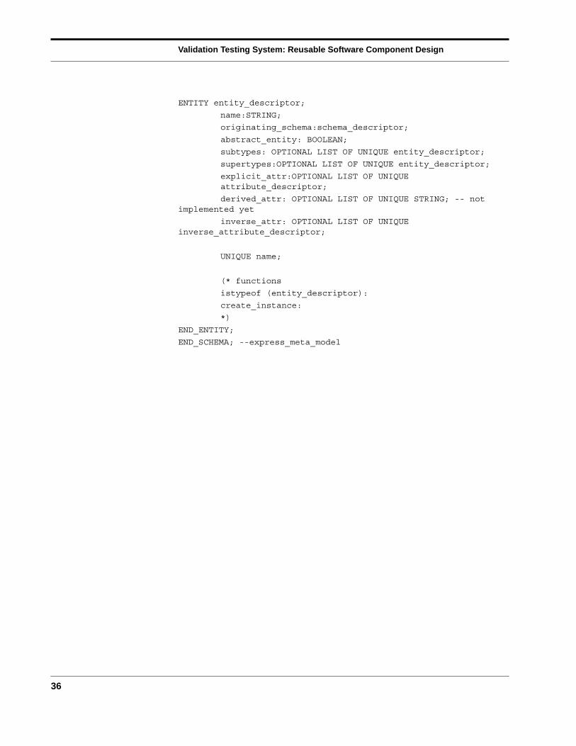
Appendix A EXPRESS Model of Registry Classes
The following EXPRESS schema is a model of EXPRESS. This model was developedas a basis for a skeleton of schema information from an EXPRESS model available atrun-time using the VTS software. (The VTS software components involved are theSTEP Class Library and a schema library generated from EXPRESS using fed-x-plus.)
With these exceptions this schema includes everything covered by EXPRESS-G:
■ intra-schema relationships
■ cardinality
■ derived attributes
SCHEMA express_meta_model;
TYPE base_type =
ENUMERATION OF (
INTEGER_TYPE, STRING_TYPE, REAL_TYPE, ENTITY_TYPE,
AGGREGATE_TYPE, ENUM_TYPE, REAL_PTR_TYPE,INTEGER_PTR_TYPE, SELECT_TYPE, BOOLEAN_TYPE,LOGICAL_TYPE, NUMBER_TYPE, BINARY_TYPE, UNKNOWN_TYPE);
(*
attribute_type =
SELECT (
base_type, type_descriptor );
*)
END_TYPE;
ENTITY type_descriptor
(* SUPERTYPE OF ( ONEOF ( real_type_descriptor,
string_type_descriptor, array_type_descriptor,
bag_type_descriptor, list_type_descriptor,
set_type_descriptor, enumeration_type_descriptor,
select_type_descriptor ))
*)
;
name:STRING ;
fundamental_type:base_type;
(* the fundamental type will default to certain values
according to the subtype of the type_descriptor *)
referent_type:type_description;
description:STRING;
END_ENTITY;
ENTITY real_type_descriptor
Validation Testing System: Reusable Software Component Design
34
SUBTYPE OF (type_descriptor);
precision_spec: OPTIONAL INTEGER;
END_ENTITY;
ENTITY string_type_descriptor
SUBTYPE OF (type_descriptor);
width: OPTIONAL INTEGER;
fixed_size: BOOLEAN;
END_ENTITY;
ENTITY aggregate_type_descriptor
ABSTRACT SUPERTYPE
SUBTYPE OF (type_descriptor);
(* The bounds spec have been simplified to integer values -- they
can actually have functional values *)
bound_1: INTEGER;
bound_2: INTEGER;
unique_elements: BOOLEAN;
aggr_domain_type:type_descriptor;
END_ENTITY;
ENTITY array_type_descriptor
SUBTYPE OF (aggregate_type_descriptor);
optional_elements: BOOLEAN;
(* WHERE exists (bound_1 && bound_2) *)
END_ENTITY;
ENTITY bag_type_descriptor
SUBTYPE OF (aggregate_type_descriptor);
(* unique_elements: always TRUE *)
END_ENTITY;
ENTITY list_type_descriptor
SUBTYPE OF (aggregate_type_descriptor);
END_ENTITY;
ENTITY set_type_descriptor
SUBTYPE OF (aggregate_type_descriptor);
(* unique_elements: always TRUE *)
END_ENTITY;
References
35
ENTITY entity_type_descriptor
SUBTYPE OF (type_descriptor);
entity_type: entity_descriptor;
END_ENTITY;
ENTITY enumeration_type_descriptor
SUBTYPE OF (type_descriptor);
elements: LIST OF UNIQUE STRING;
END_ENTITY;
ENTITY select_type_descriptor
SUBTYPE OF (type_descriptor);
elements: LIST OF UNIQUE type_descriptor;
END_ENTITY;
ENTITY attribute_descriptor;
name:STRING;
domain_type:type_descriptor;
optional_value:BOOLEAN;
unique_value:BOOLEAN;
owner:entity_descriptor;
END_ENTITY;
ENTITY inverse_attribute_descriptor
SUBTYPE OF (attribute_descriptor);
inverse_attribute : attribute_descriptor;
(*
role_attr: ExplicitAttribute;
min_cardinality: bound_description;
max_cardinality: bound_description;
duplicates: OPTIONAL BOOLEAN;
(* 3-Apr-1992 kcm
WHERE
uniqueness_correct: (EXISTS (duplicates) AND max_cardinality > 1)OR
(max_cardinality = 1 AND NOT EXISTS (duplicates);
*)
*)
END_ENTITY;
ENTITY schema_descriptor;
name:STRING;
END_ENTITY;
Validation Testing System: Reusable Software Component Design
36
ENTITY entity_descriptor;
name:STRING;
originating_schema:schema_descriptor;
abstract_entity: BOOLEAN;
subtypes: OPTIONAL LIST OF UNIQUE entity_descriptor;
supertypes:OPTIONAL LIST OF UNIQUE entity_descriptor;
explicit_attr:OPTIONAL LIST OF UNIQUEattribute_descriptor;
derived_attr: OPTIONAL LIST OF UNIQUE STRING; -- notimplemented yet
inverse_attr: OPTIONAL LIST OF UNIQUEinverse_attribute_descriptor;
UNIQUE name;
(* functions
istypeof (entity_descriptor):
create_instance:
*)
END_ENTITY;
END_SCHEMA; --express_meta_model
References
37
Appendix B VTS Document Series
This document complements others in the National PDES Testbed Report Series whichprovide detailed technical information relating to the Testbed software. Those docu-ments which specifically address aspects of the Validation Testing System are describedbelow.
Validation Testing Systems Plan lays out the tasks and the overall approach for theinitial implementation of the Validation Testing System. (NISTIR 4417)
Proposed Testing Methodology for STEP Application Protocol Validation describes thecomplete process used to develop and validate application protocols. This methodologydocument focuses on the analysis of application models and planning for validationtesting. (NISTIR 4684)
Validating STEP Application Models at the National PDES Testbed describes a strategyfor automation based on an analysis of the information flow in the application protocoldevelopment and testing process, and on initial experiences with automation for valida-tion testing at the National PDES Testbed. (NISTIR 4735)
Validation Testing System Requirements describes functional requirements for automa-tion of the VTS. This document also provides an overview of the VTS software environ-ment. Requirements for the VTS system are driven by the STEP development effort andreflect the needs of the National PDES Testbed users. (NISTIR 4676)
Architecture for the Validation Testing System Software describes an architecture forsoftware which supports the testing of information models for validity and correctness.The architecture provides a basis for software development within the National PDESTestbed. (NISTIR 4742)
Validation Testing System: Reusable Software Component Design provides guidelinesfor the implementation of the VTS software. The document describes the design of soft-ware libraries which fit within the VTS architecture. These libraries enable the creationand support of tool which support the VTS testing methodology. Designs for the compo-nents of the software are also provided. (NISTIR 4937)