Embed Size (px)
Citation preview
2003/10 – Subject to change – Products 2004/2005 2 / 2.1−1
�Electrically actuated valves
�Performance optimised sizes
�Minimal width
�High flow rates
�Low power consumption
Dir
ecti
onal
con
trol
val
ves
for
stan
dard
app
lica
tion
s
Com
pact
Per
form
ance
2.1
Valves CPE, Compact Performance
Products 2004/2005 – Subject to change – 2003/102 / 2.1−2
Solenoid valves CPE, Compact PerformanceFeatures
Function1)
1) 3/2−way, e.g. with external pilot air,
normally closed
1) 5/2−way, single solenoid, e.g. with external
pilot air
1) 5/2−way, double solenoid, e.g. with
external pilot air
1) 5/3−way, e.g. with external pilot air,
normally closed
−K− Width
10 ... 24 mm
−M− Flow rate
180 ... 3,200 l/min
−P− Voltage
24 V DC
110 V AC
230 V AC
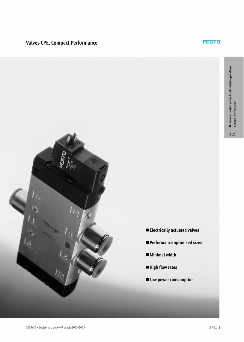
Performance optimised sizes
The solenoid valves CPE, Compact
Performance are distinguished by
their minimal width and low power
consumption at high flow rates.
Can be mounted on site:
— on cylinders,
— on moving system components.
— Choice of installation either
individual, top−hat rail or wall
mounted.
Micro CPE10, Mini CPE14 and
Midi CPE18:
Simple structure comprising compact
valve manifolds through modular
manifold blocks.
Possible combinations � 2 / 2.1−58
Shorter tubing lengths with minimal
air volumes:
— fast switching times
— quick reaction times
Optimised installations:
— shorter machine cycles
— larger quantities
— low power consumption
Convenient manual override
A current reduction function has been
integrated in the KMYZ−9 plug socket
for sizes Micro CPE10 and Mini
CPE14.
Dir
ecti
onal
con
trol
val
ves
for
stan
dard
app
lica
tion
s
Com
pact
Per
form
ance
2.1
2003/10 – Subject to change – Products 2004/2005 2 / 2.1−3
Solenoid valves CPE, Compact PerformanceFeatures
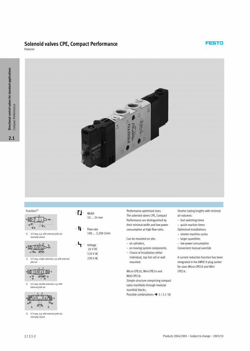
Manifold assembly for Micro CPE10, Mini CPE14 and Midi CPE18
— From individual valves through to
compact valve manifolds thanks to
modular sub−base systems made
from high impact, fibre glass
reinforced polyamide.
— Different pressure zones can be
implemented with closed PRS
channels in basic and expansion
blocks.
— Supply and exhaust air can be
connected at both ends with
connections on basic and end
blocks.
— Supply and exhaust air can be
connected at the end block, both
from the side and from the top.
— No screws required for mounting
thanks to quick connecting clips.
— Possible combinations
� 2 / 2.1−58
End block
Expansion block
Expansion block
Basic block for 2 valves
Basic block
for 3 valves
14
2
12
4
5
14
2
12
4
1
3
Dir
ecti
onal
con
trol
val
ves
for
stan
dard
app
lica
tion
s
Com
pact
Per
form
ance
2.1
Products 2004/2005 – Subject to change – 2004/102 / 2.1−4
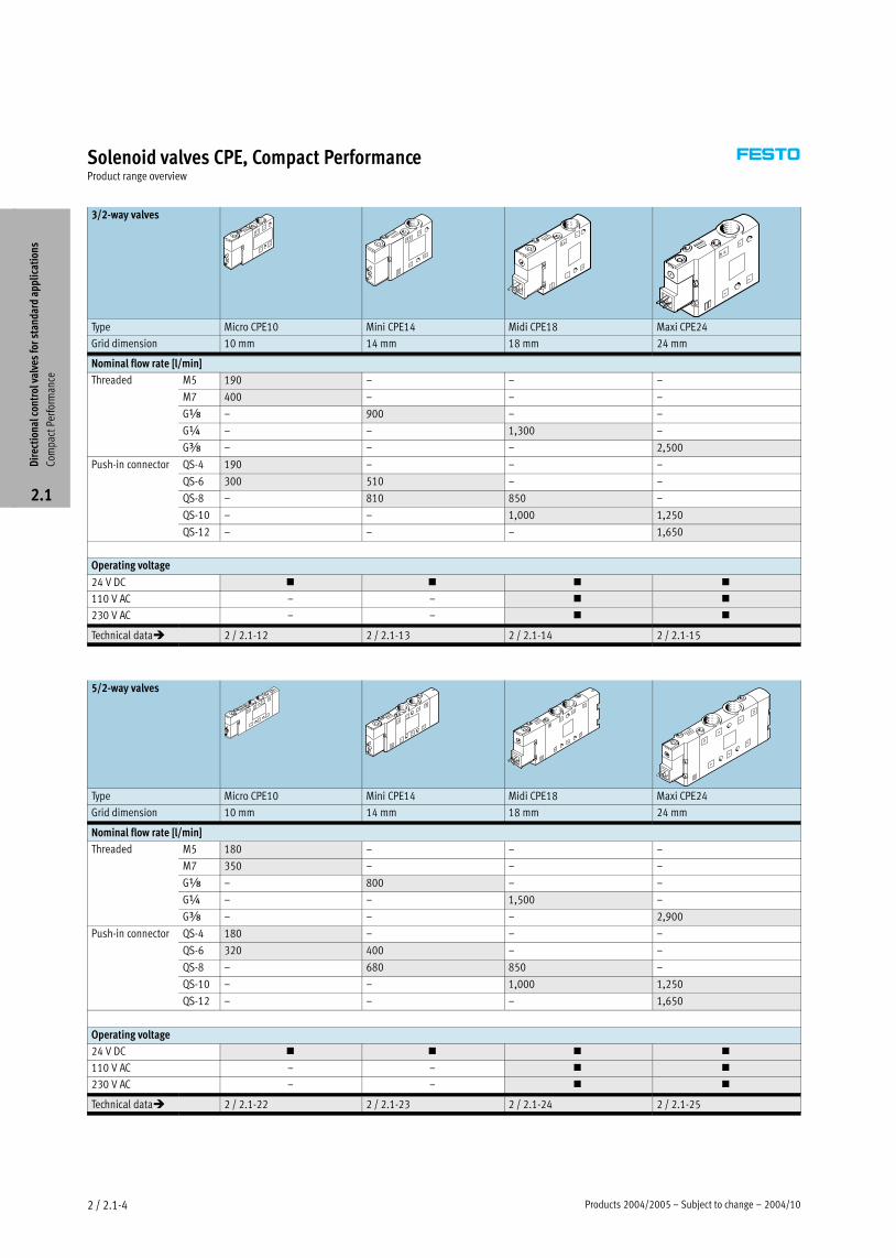
Solenoid valves CPE, Compact PerformanceProduct range overview
3/2−way valves
Type Micro CPE10 Mini CPE14 Midi CPE18 Maxi CPE24
Grid dimension 10 mm 14 mm 18 mm 24 mm
Nominal flow rate [l/min]
Threaded M5 190 – – –
M7 400 – – –
Gx – 900 – –
G¼ – – 1,300 –
Gy – – – 2,500
Push−in connector QS−4 190 – – –
QS−6 300 510 – –
QS−8 – 810 850 –
QS−10 – – 1,000 1,250
QS−12 – – – 1,650
Operating voltage
24 V DC � � � �
110 V AC – – � �
230 V AC – – � �
Technical data� 2 / 2.1−12 2 / 2.1−13 2 / 2.1−14 2 / 2.1−15
5/2−way valves
Type Micro CPE10 Mini CPE14 Midi CPE18 Maxi CPE24
Grid dimension 10 mm 14 mm 18 mm 24 mm
Nominal flow rate [l/min]
Threaded M5 180 – – –
M7 350 – – –
Gx – 800 – –
G¼ – – 1,500 –
Gy – – – 2,900
Push−in connector QS−4 180 – – –
QS−6 320 400 – –
QS−8 – 680 850 –
QS−10 – – 1,000 1,250
QS−12 – – – 1,650
Operating voltage
24 V DC � � � �
110 V AC – – � �
230 V AC – – � �
Technical data� 2 / 2.1−22 2 / 2.1−23 2 / 2.1−24 2 / 2.1−25
Dir
ecti
onal
con
trol
val
ves
for
stan
dard
app
lica
tion
s
Com
pact
Per
form
ance
2.1

2004/10 – Subject to change – Products 2004/2005 2 / 2.1−5
Solenoid valves CPE, Compact PerformanceProduct range overview
5/2−way valves,
Double solenoid valves
Type Micro CPE10 Mini CPE14 Midi CPE18 Maxi CPE24
Grid dimension 10 mm 14 mm 18 mm 24 mm
Nominal flow rate [l/min]
Threaded M5 180 – – –
M7 350 – – –
Gx – 800 – –
G¼ – – 1,500 –
Gy – – – 3,200
Push−in connector QS−4 180 – – –
QS−6 320 400 – –
QS−8 – 680 850 –
QS−10 – – 1,000 1,250
QS−12 – – – 1,650
Operating voltage
24 V DC � � � �
110 V AC – – � �
230 V AC – – � �
Technical data� 2 / 2.1−32 2 / 2.1−33 2 / 2.1−34 2 / 2.1−35
5/3−way valves
Type Micro CPE10 Mini CPE14 Midi CPE18 Maxi CPE24
Grid dimension 10 mm 14 mm 18 mm 24 mm
Nominal flow rate [l/min]
Threaded M5 180 – – –
M7 250 ... 350 – – –
Gx – 700 ... 750 – –
G¼ – – 1,200 ... 1,450 –
Gy – – – 2,600 ... 3,000
Push−in connector QS−4 180 – – –
QS−6 250 ... 300 370 ... 410 – –
QS−8 – 570 ... 720 780 ... 850 –
QS−10 – – 1,000 ... 1,050 1,250
QS−12 – – – 1,600 ... 1,650
Operating voltage
24 V DC � � � �
110 V AC – – � �
230 V AC – – � �
Technical data� 2 / 2.1−41 2 / 2.1−42 2 / 2.1−43 2 / 2.1−44
Dir
ecti
onal
con
trol
val
ves
for
stan
dard
app
lica
tion
s
Com
pact
Per
form
ance
2.1
Products 2004/2005 – Subject to change – 2004/102 / 2.1−6
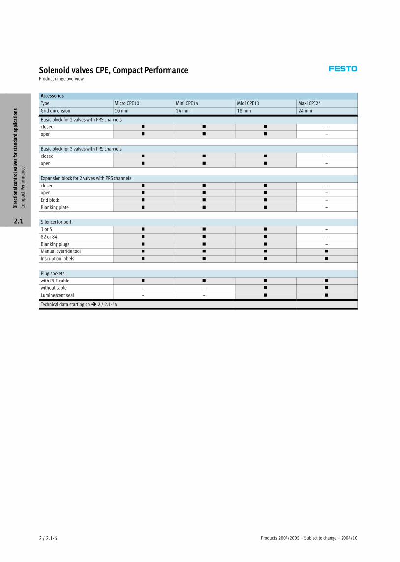
Solenoid valves CPE, Compact PerformanceProduct range overview
Accessories
Type Micro CPE10 Mini CPE14 Midi CPE18 Maxi CPE24
Grid dimension 10 mm 14 mm 18 mm 24 mm
Basic block for 2 valves with PRS channels
closed � � � –
open � � � –
Basic block for 3 valves with PRS channels
closed � � � –
open � � � –
Expansion block for 2 valves with PRS channels
closed � � � –
open � � � –
End block � � � –
Blanking plate � � � –
Silencer for port
3 or 5 � � � –
82 or 84 � � � –
Blanking plugs � � � –
Manual override tool � � � �
Inscription labels � � � �
Plug sockets
with PUR cable � � � �
without cable – – � �
Luminescent seal – – � �
Technical data starting on � 2 / 2.1−54
Dir
ecti
onal
con
trol
val
ves
for
stan
dard
app
lica
tion
s
Com
pact
Per
form
ance
2.1
2004/10 – Subject to change – Products 2004/2005 2 / 2.1−7
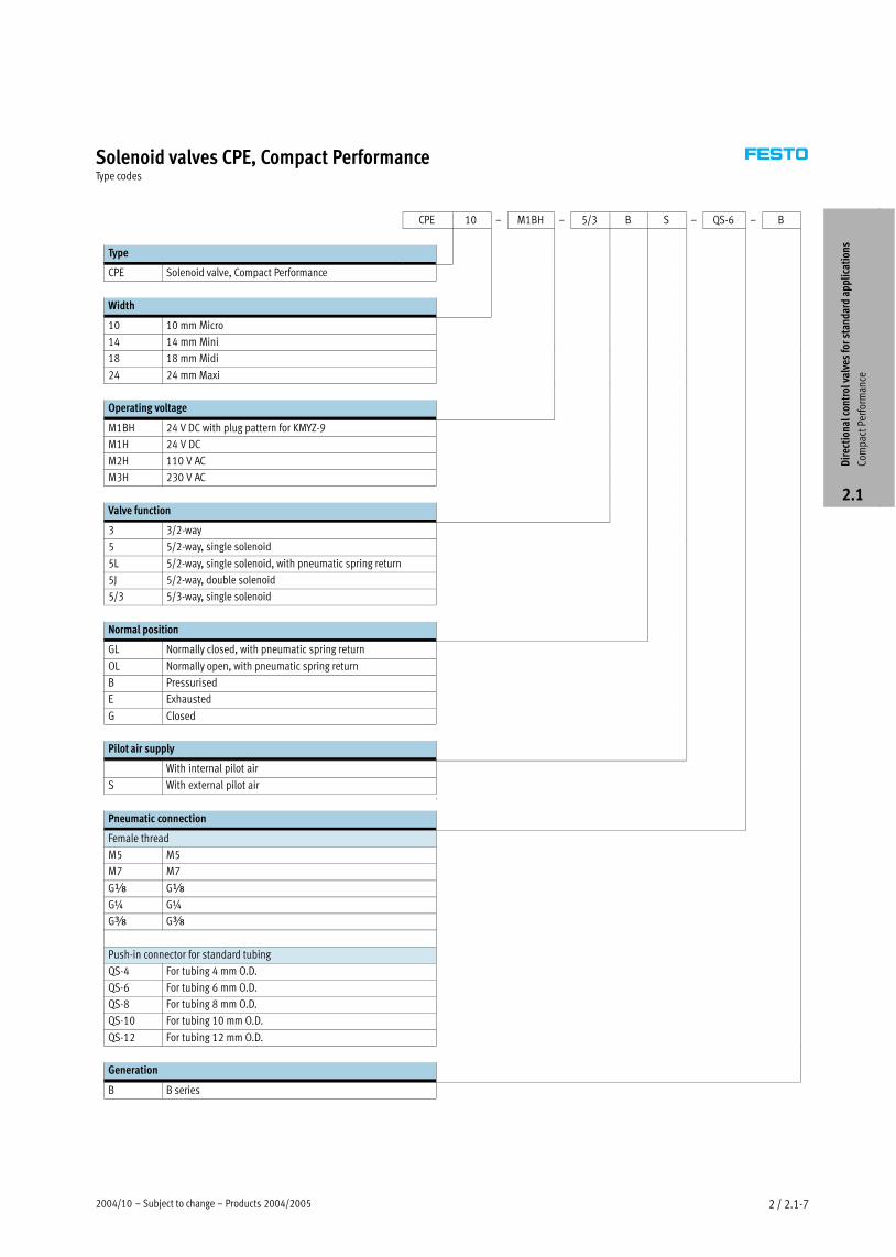
Solenoid valves CPE, Compact PerformanceType codes
CPE 10 – M1BH – 5/3 B S – QS−6 – B
Type
CPE Solenoid valve, Compact Performance
Width
10 10 mm Micro
14 14 mm Mini
18 18 mm Midi
24 24 mm Maxi
Operating voltage
M1BH 24 V DC with plug pattern for KMYZ−9
M1H 24 V DC
M2H 110 V AC
M3H 230 V AC
Valve function
3 3/2−way
5 5/2−way, single solenoid
5L 5/2−way, single solenoid, with pneumatic spring return
5J 5/2−way, double solenoid
5/3 5/3−way, single solenoid
Normal position
GL Normally closed, with pneumatic spring return
OL Normally open, with pneumatic spring return
B Pressurised
E Exhausted
G Closed
Pilot air supply
With internal pilot air
S With external pilot airt
Pneumatic connection
Female thread
M5 M5
M7 M7
Gx Gx
G¼ G¼
Gy Gy
Push−in connector for standard tubing
QS−4 For tubing 4 mm O.D.
QS−6 For tubing 6 mm O.D.
QS−8 For tubing 8 mm O.D.
QS−10 For tubing 10 mm O.D.
QS−12 For tubing 12 mm O.D.
Generation
B B series
Dir
ecti
onal
con
trol
val
ves
for
stan
dard
app
lica
tion
s
Com
pact
Per
form
ance
2.1
Products 2004/2005 – Subject to change – 2004/102 / 2.1−8
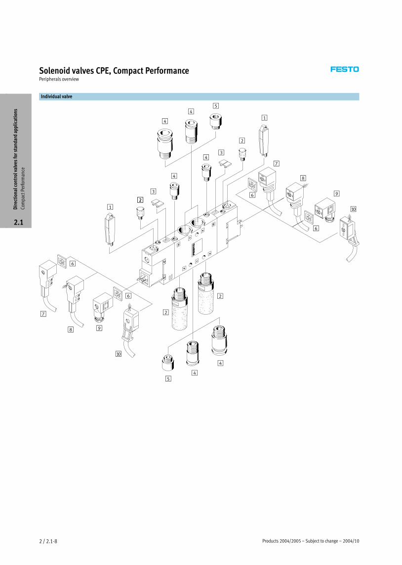
Solenoid valves CPE, Compact PerformancePeripherals overview
Individual valve
1
2
3
4
98
7
6
aJ
1
2
2
34
4
45
54
4
6
6
6
7
8
9
aJ
2
2
Dir
ecti
onal
con
trol
val
ves
for
stan
dard
app
lica
tion
s
Com
pact
Per
form
ance
2.1
2004/10 – Subject to change – Products 2004/2005 2 / 2.1−9
Solenoid valves CPE, Compact PerformancePeripherals overview
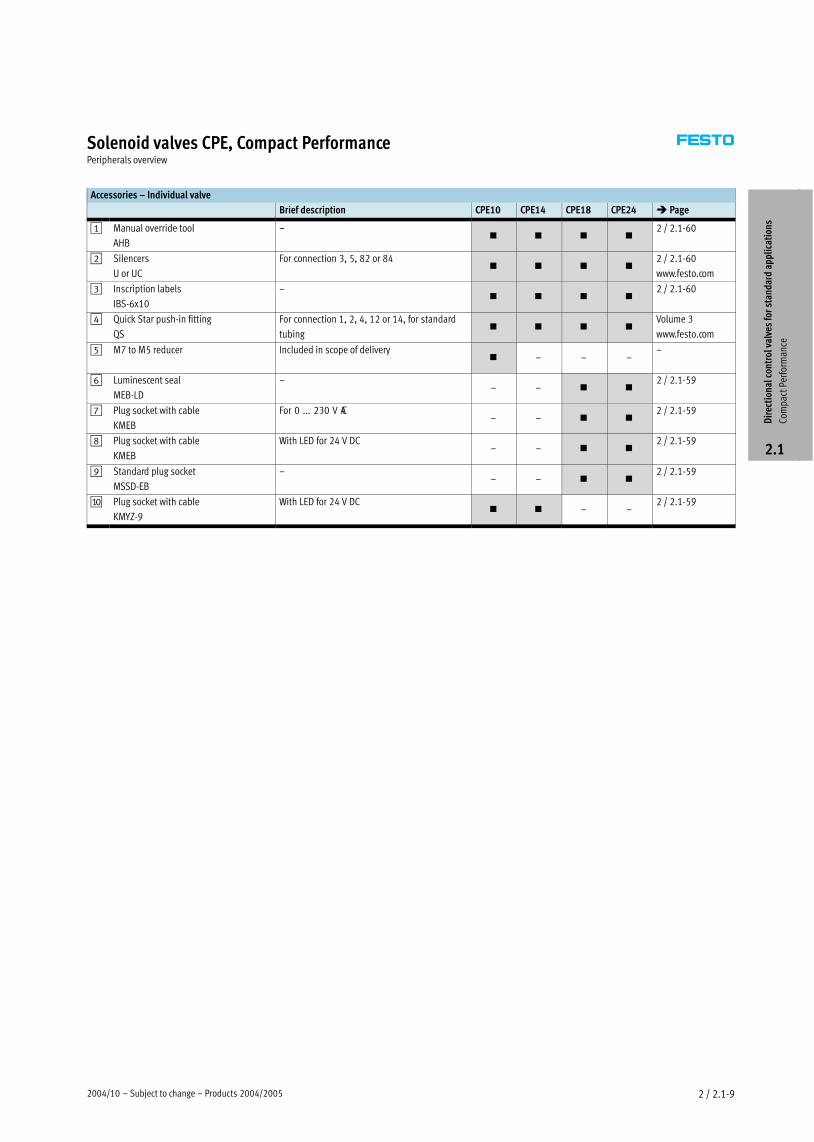
Accessories – Individual valve
Brief description CPE10 CPE14 CPE18 CPE24 � Page
1 Manual override tool
AHB
–� � � �
2 / 2.1−60
2 Silencers
U or UC
For connection 3, 5, 82 or 84� � � �
2 / 2.1−60
www.festo.com
3 Inscription labels
IBS−6x10
–� � � �
2 / 2.1−60
4 Quick Star push−in fitting
QS
For connection 1, 2, 4, 12 or 14, for standard
tubing� � � �
Volume 3
www.festo.com
5 M7 to M5 reducer Included in scope of delivery� – – –
–
6 Luminescent seal
MEB-LD
–– – � �
2 / 2.1−59
7 Plug socket with cable
KMEB
For 0 ... 230 V AC– – � �
2 / 2.1−59
8 Plug socket with cable
KMEB
With LED for 24 V DC– – � �
2 / 2.1−59
9 Standard plug socket
MSSD-EB
–– – � �
2 / 2.1−59
aJ Plug socket with cable
KMYZ−9
With LED for 24 V DC� � – –
2 / 2.1−59
Dir
ecti
onal
con
trol
val
ves
for
stan
dard
app
lica
tion
s
Com
pact
Per
form
ance
2.1
Products 2004/2005 – Subject to change – 2004/102 / 2.1−10
Solenoid valves CPE, Compact PerformancePeripherals overview
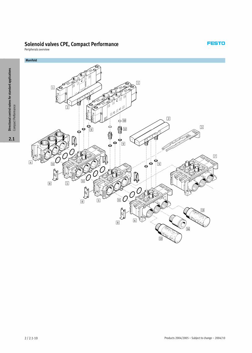
Manifold
1
8
8
9
1
2
2
3
5
4
5
6
7
8
aJ
9
aB
9
aC
aC
aD
aA
aA
aA
Dir
ecti
onal
con
trol
val
ves
for
stan
dard
app
lica
tion
s
Com
pact
Per
form
ance
2.1
2004/10 – Subject to change – Products 2004/2005 2 / 2.1−11
Solenoid valves CPE, Compact PerformancePeripherals overview
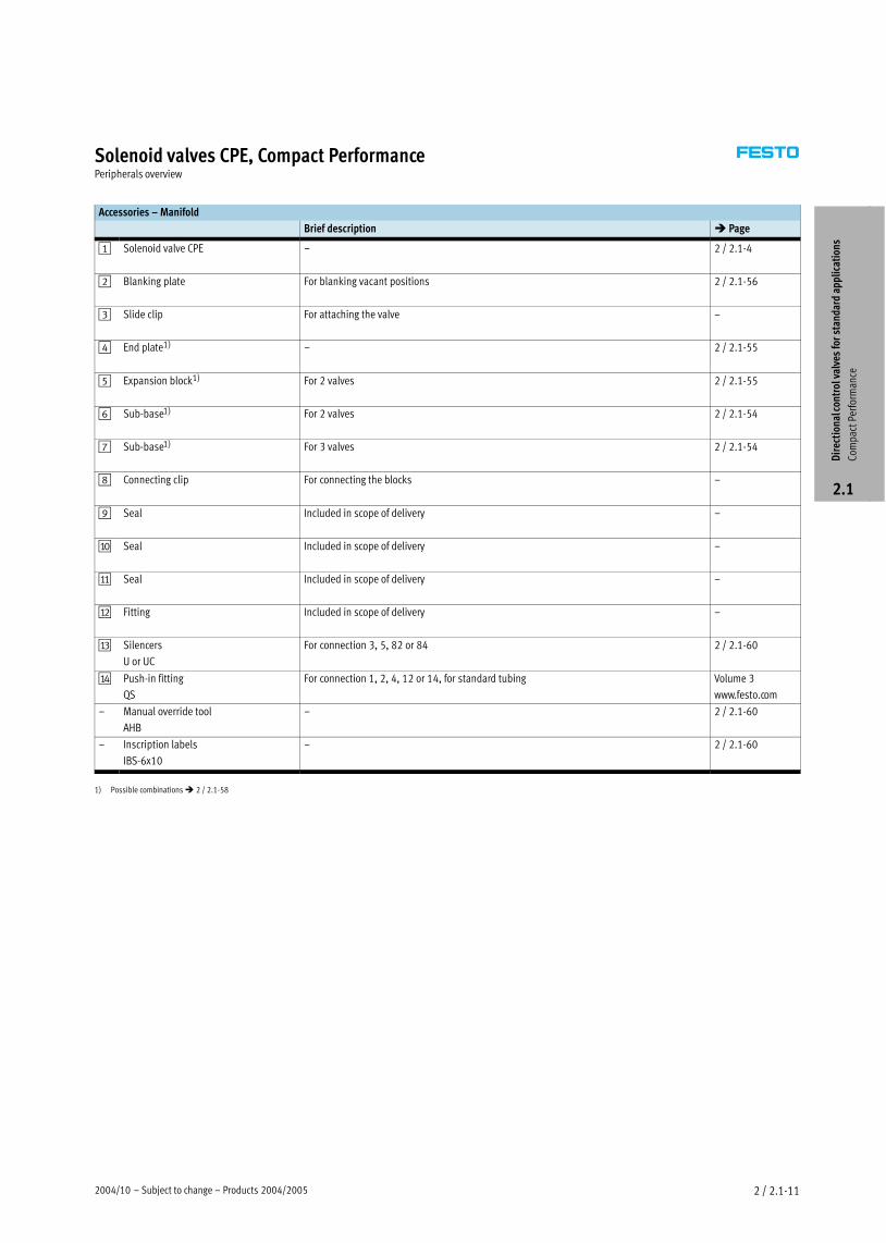
Accessories – Manifold
Brief description � Page
1 Solenoid valve CPE – 2 / 2.1−4
2 Blanking plate For blanking vacant positions 2 / 2.1−56
3 Slide clip For attaching the valve –
4 End plate1) – 2 / 2.1−55
5 Expansion block1) For 2 valves 2 / 2.1−55
6 Sub−base1) For 2 valves 2 / 2.1−54
7 Sub−base1) For 3 valves 2 / 2.1−54
8 Connecting clip For connecting the blocks –
9 Seal Included in scope of delivery –
aJ Seal Included in scope of delivery –
aA Seal Included in scope of delivery –
aB Fitting Included in scope of delivery –
aC Silencers
U or UC
For connection 3, 5, 82 or 84 2 / 2.1−60
aD Push−in fitting
QS
For connection 1, 2, 4, 12 or 14, for standard tubing Volume 3
www.festo.com
– Manual override tool
AHB
– 2 / 2.1−60
– Inscription labels
IBS−6x10
– 2 / 2.1−60
1) Possible combinations � 2 / 2.1−58
Dir
ecti
onal
con
trol
val
ves
for
stan
dard
app
lica
tion
s
Com
pact
Per
form
ance
2.1

Products 2004/2005 – Subject to change – 2005/042 / 2.1−12
Solenoid valves CPE, Compact PerformanceTechnical data – 3/2−way valves
Function1)
1) e.g. with external pilot air, normally closed
−M− Flow rate
190 Ī 2,500 l/min
−P− Voltage
24 V DC
110, 230 V AC
General technical data – Micro CPE10
Threaded connection Push−in connector
Valve function 3/2, single solenoid
Design Piston spool
Sealing principle Soft
Actuation type Electrical
Type of reset Pneumatic
Type of control Piloted
Pilot air supply Internal or external
Direction of flow Internal pilot air supply: non−reversible
External pilot air supply: reversible
Exhaust function With flow control
Manual override Resetting, detenting via tool accessory
Mounting position Any
Width 10 mm
Grid dimension 12 mm
Nominal size 4 mm 4 mm
Standard nominal flow rate M5: 190 l/min QS−4: 190 l/min
M7: 400 l/min QS−6: 300 l/min
Type of mounting Via through−holes
Pneumatic connection 1, 2 M5 or M7 ∅ 4 or ∅ 6 mm
3 M7 M7
10, 12 M3 ∅ 3 mm
82 M3 M3
Response time on/off 14/14 ms
Product weight 45 g
Materials � 2 / 2.1−16
Operating and environmental conditions
Threaded connection Push−in connector
Operating medium Filtered compressed air, lubricated or unlubricated
Vacuum
Operating pressure range internal pilot air 2.5 Ī8 barp g p g
external pilot air –0.9 Ī+10 bar
Pilot pressure range 2.5 Ī8 bar
Ambient temperature –5 Ī +50 °C
Temperature of medium –5 Ī +50 °C
Electrical data
Threaded connection Push−in connector
Operating voltage 24 V DC +10/−15%
Power consumption 1.28 W
Degree of protection with plug socket IP65 (EN 60 529)
Dir
ecti
onal
con
trol
val
ves
for
stan
dard
app
lica
tion
s
Com
pact
Per
form
ance
2.1
2005/04 – Subject to change – Products 2004/2005 2 / 2.1−13
Solenoid valves CPE, Compact PerformanceTechnical data – 3/2−way valves
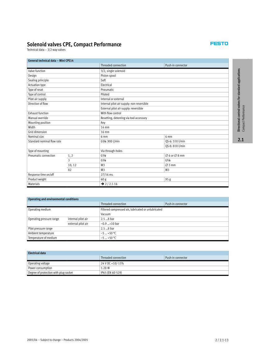
General technical data – Mini CPE14
Threaded connection Push−in connector
Valve function 3/2, single solenoid
Design Piston spool
Sealing principle Soft
Actuation type Electrical
Type of reset Pneumatic
Type of control Piloted
Pilot air supply Internal or external
Direction of flow Internal pilot air supply: non−reversible
External pilot air supply: reversible
Exhaust function With flow control
Manual override Resetting, detenting via tool accessory
Mounting position Any
Width 14 mm
Grid dimension 16 mm
Nominal size 6 mm 6 mm
Standard nominal flow rate Gx: 900 l/min QS−6: 510 l/minx 9 /
QS−8: 810 l/min
Type of mounting Via through−holes
Pneumatic connection 1, 2 Gx ∅ 6 or ∅ 8 mm
3 Gx Gx
10, 12 M3 ∅ 3 mm
82 M3 M3
Response time on/off 27/16 ms
Product weight 60 g 95 g
Materials � 2 / 2.1−16
Operating and environmental conditions
Threaded connection Push−in connector
Operating medium Filtered compressed air, lubricated or unlubricated
Vacuum
Operating pressure range internal pilot air 2.5 Ī8 barp g p g
external pilot air –0.9 Ī+10 bar
Pilot pressure range 2.5 Ī8 bar
Ambient temperature –5 Ī +50 °C
Temperature of medium –5 Ī +50 °C
Electrical data
Threaded connection Push−in connector
Operating voltage 24 V DC +10/−15%
Power consumption 1.28 W
Degree of protection with plug socket IP65 (EN 60 529)
Dir
ecti
onal
con
trol
val
ves
for
stan
dard
app
lica
tion
s
Com
pact
Per
form
ance
2.1
Products 2004/2005 – Subject to change – 2005/042 / 2.1−14
Solenoid valves CPE, Compact PerformanceTechnical data – 3/2−way valves
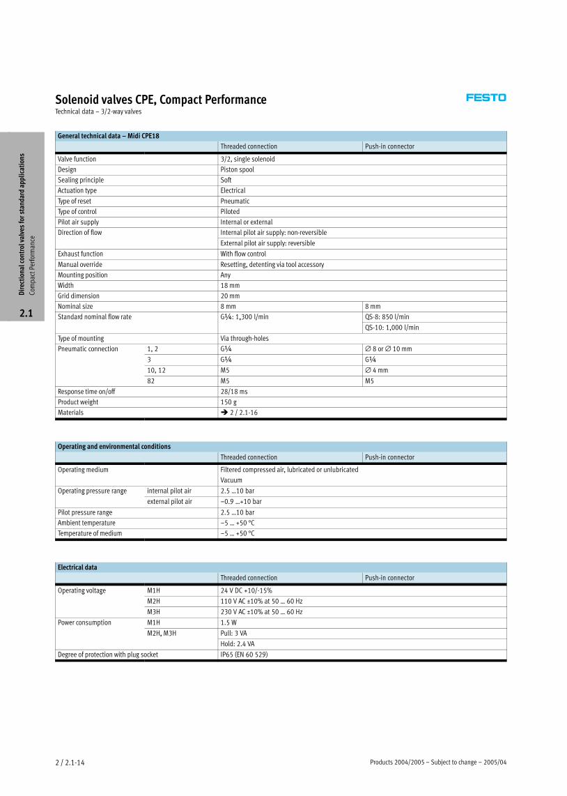
General technical data – Midi CPE18
Threaded connection Push−in connector
Valve function 3/2, single solenoid
Design Piston spool
Sealing principle Soft
Actuation type Electrical
Type of reset Pneumatic
Type of control Piloted
Pilot air supply Internal or external
Direction of flow Internal pilot air supply: non−reversible
External pilot air supply: reversible
Exhaust function With flow control
Manual override Resetting, detenting via tool accessory
Mounting position Any
Width 18 mm
Grid dimension 20 mm
Nominal size 8 mm 8 mm
Standard nominal flow rate G¼: 1,300 l/min QS−8: 850 l/min¼ ,3 /
QS−10: 1,000 l/min
Type of mounting Via through−holes
Pneumatic connection 1, 2 G¼ ∅ 8 or ∅ 10 mm
3 G¼ G¼
10, 12 M5 ∅ 4 mm
82 M5 M5
Response time on/off 28/18 ms
Product weight 150 g
Materials � 2 / 2.1−16
Operating and environmental conditions
Threaded connection Push−in connector
Operating medium Filtered compressed air, lubricated or unlubricated
Vacuum
Operating pressure range internal pilot air 2.5 Ī10 barp g p g
external pilot air –0.9 Ī+10 bar
Pilot pressure range 2.5 Ī10 bar
Ambient temperature –5 Ī +50 °C
Temperature of medium –5 Ī +50 °C
Electrical data
Threaded connection Push−in connector
Operating voltage M1H 24 V DC +10/−15%p g g
M2H 110 V AC ±10% at 50 Ī 60 Hz
M3H 230 V AC ±10% at 50 Ī 60 Hz
Power consumption M1H 1.5 Wp
M2H, M3H Pull: 3 VA, 3
Hold: 2.4 VA
Degree of protection with plug socket IP65 (EN 60 529)
Dir
ecti
onal
con
trol
val
ves
for
stan
dard
app
lica
tion
s
Com
pact
Per
form
ance
2.1
2005/04 – Subject to change – Products 2004/2005 2 / 2.1−15
Solenoid valves CPE, Compact PerformanceTechnical data – 3/2−way valves
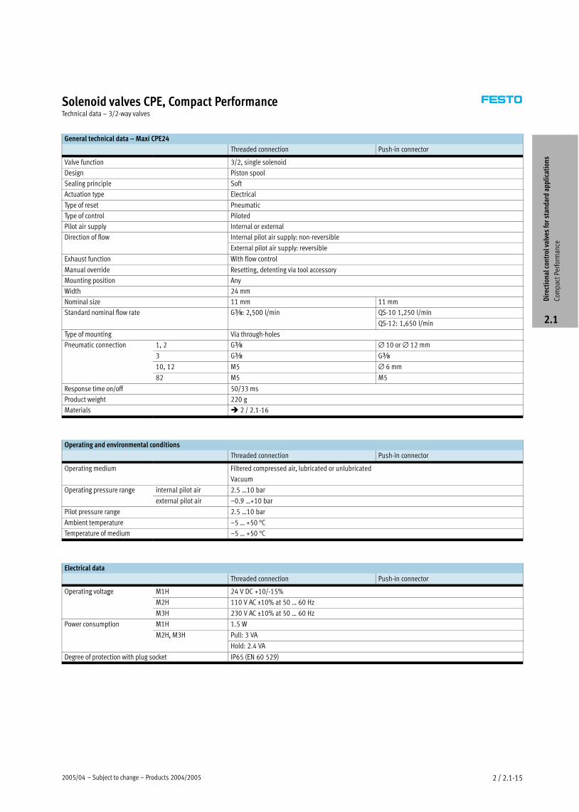
General technical data – Maxi CPE24
Threaded connection Push−in connector
Valve function 3/2, single solenoid
Design Piston spool
Sealing principle Soft
Actuation type Electrical
Type of reset Pneumatic
Type of control Piloted
Pilot air supply Internal or external
Direction of flow Internal pilot air supply: non−reversible
External pilot air supply: reversible
Exhaust function With flow control
Manual override Resetting, detenting via tool accessory
Mounting position Any
Width 24 mm
Nominal size 11 mm 11 mm
Standard nominal flow rate Gy: 2,500 l/min QS−10 1,250 l/miny ,5 /
QS−12: 1,650 l/min
Type of mounting Via through−holes
Pneumatic connection 1, 2 Gy ∅ 10 or ∅ 12 mm
3 Gy Gy
10, 12 M5 ∅ 6 mm
82 M5 M5
Response time on/off 50/33 ms
Product weight 220 g
Materials � 2 / 2.1−16
Operating and environmental conditions
Threaded connection Push−in connector
Operating medium Filtered compressed air, lubricated or unlubricated
Vacuum
Operating pressure range internal pilot air 2.5 Ī10 barp g p g
external pilot air –0.9 Ī+10 bar
Pilot pressure range 2.5 Ī10 bar
Ambient temperature –5 Ī +50 °C
Temperature of medium –5 Ī +50 °C
Electrical data
Threaded connection Push−in connector
Operating voltage M1H 24 V DC +10/−15%p g g
M2H 110 V AC ±10% at 50 Ī 60 Hz
M3H 230 V AC ±10% at 50 Ī 60 Hz
Power consumption M1H 1.5 Wp
M2H, M3H Pull: 3 VA, 3
Hold: 2.4 VA
Degree of protection with plug socket IP65 (EN 60 529)
Dir
ecti
onal
con
trol
val
ves
for
stan
dard
app
lica
tion
s
Com
pact
Per
form
ance
2.1
Products 2004/2005 – Subject to change – 2005/042 / 2.1−16
Solenoid valves CPE, Compact PerformanceTechnical data – 3/2−way valves
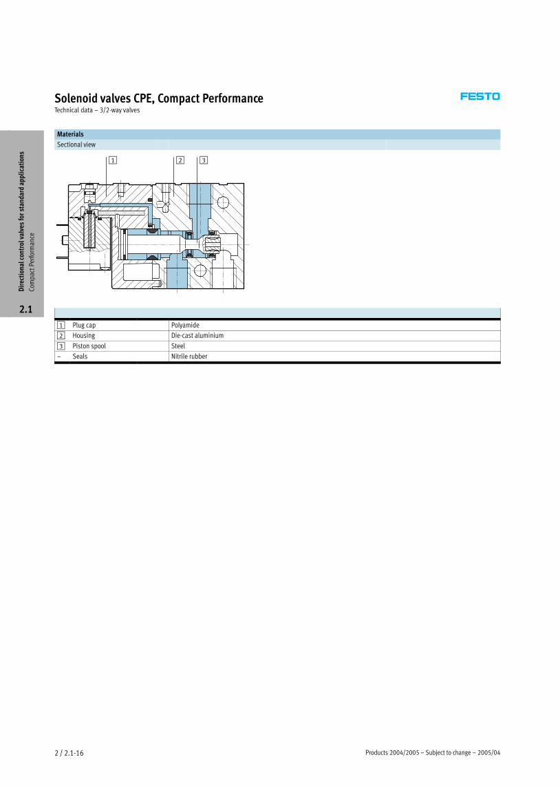
Materials
Sectional view
1 2 3
1 Plug cap Polyamide
2 Housing Die−cast aluminium
3 Piston spool Steel
– Seals Nitrile rubber
Dir
ecti
onal
con
trol
val
ves
for
stan
dard
app
lica
tion
s
Com
pact
Per
form
ance
2.1
2005/04 – Subject to change – Products 2004/2005 2 / 2.1−17
Solenoid valves CPE, Compact PerformanceTechnical data – 3/2−way valves
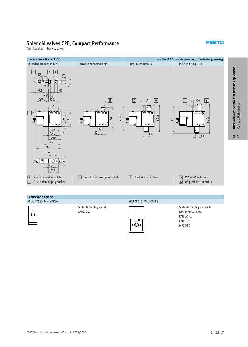
Dimensions – Micro CPE10 Download CAD data � www.festo.com/en/engineering
Threaded connection M7 Threaded connection M5 Push−in fitting QS−4 Push−in fitting QS−6
1 Manual override facility
2 Connection for plug socket
3 Location for inscription labels 4 Pilot air connection 5 M7 to M5 reducer
6 QS push−in connection
Connection diagrams
Micro CPE10, Mini CPE14 Midi CPE18, Maxi CPE24
Suitable for plug socket
KMYZ−9−...
Suitable for plug sockets to
DIN 43 650, type C
KMEB−1−...
KMEB−2−...
MSSD−EB
Dir
ecti
onal
con
trol
val
ves
for
stan
dard
app
lica
tion
s
Com
pact
Per
form
ance
2.1

Products 2004/2005 – Subject to change – 2005/042 / 2.1−18
Solenoid valves CPE, Compact PerformanceTechnical data – 3/2−way valves
Dimensions – Mini CPE14, Midi CPE18, Maxi CPE24 Download CAD data � www.festo.com/en/engineering
Threaded connection Push−in connector
1 Manual override facility
2 Connection for plug socket
3 Location for inscription
labels
4 Pilot air connection
6 QS push−in connection
Pneumatic
connection
B1 B2 B3 B4 D1 D2 D3
∅D4
∅D5
∅H1 H2 H3
Mini CPE14
Gx 14 10 3.5 3.5 Gx M3 4.4 – – 40.3 26 7
QS−6
3 5 3 5 x 3
6 3
3 7
QS−8 8
3
Midi CPE18
G¼ 18 17.5 3.5 3.5 G¼ M5 4.4 – – 57 45 6
QS−8
7 5 3 5 3 5 ¼ 5
8 6
57 5
QS−10 10
Maxi CPE24
Gy 24 17.5 6 6 Gy M5 6.5 – – 62 40 11
QS−10
7 5 y 5 5
10 6
QS−12 12
Pneumatic
connection
H4 H5 L1 L2 L3 L4 L5 L6 L7 L8 L9 L10
Mini CPE14
Gx – – 67 50.5 35 18.3 27 9.5 20 5 32 18.3
QS−6 75.3 70.9
7 5 5 35 3 7 9 5 5 3 3
QS−8 86.3 76.4
Midi CPE18
G¼ – – 94 69 50 28 38 17.5 29 5.5 44 27.5
QS−8 98 90.5
9 9 5 3 7 5 9 5 5 7 5
QS−10 105 94
Maxi CPE24
Gy – – 110 85 65 35 50 20 33 10 45 35
QS−10 108 99.5
5 5 35 5 33 5 35
QS−12 113 102
Dir
ecti
onal
con
trol
val
ves
for
stan
dard
app
lica
tion
s
Com
pact
Per
form
ance
2.1
2005/04 – Subject to change – Products 2004/2005 2 / 2.1−19
Solenoid valves CPE, Compact PerformanceTechnical data – 3/2−way valves
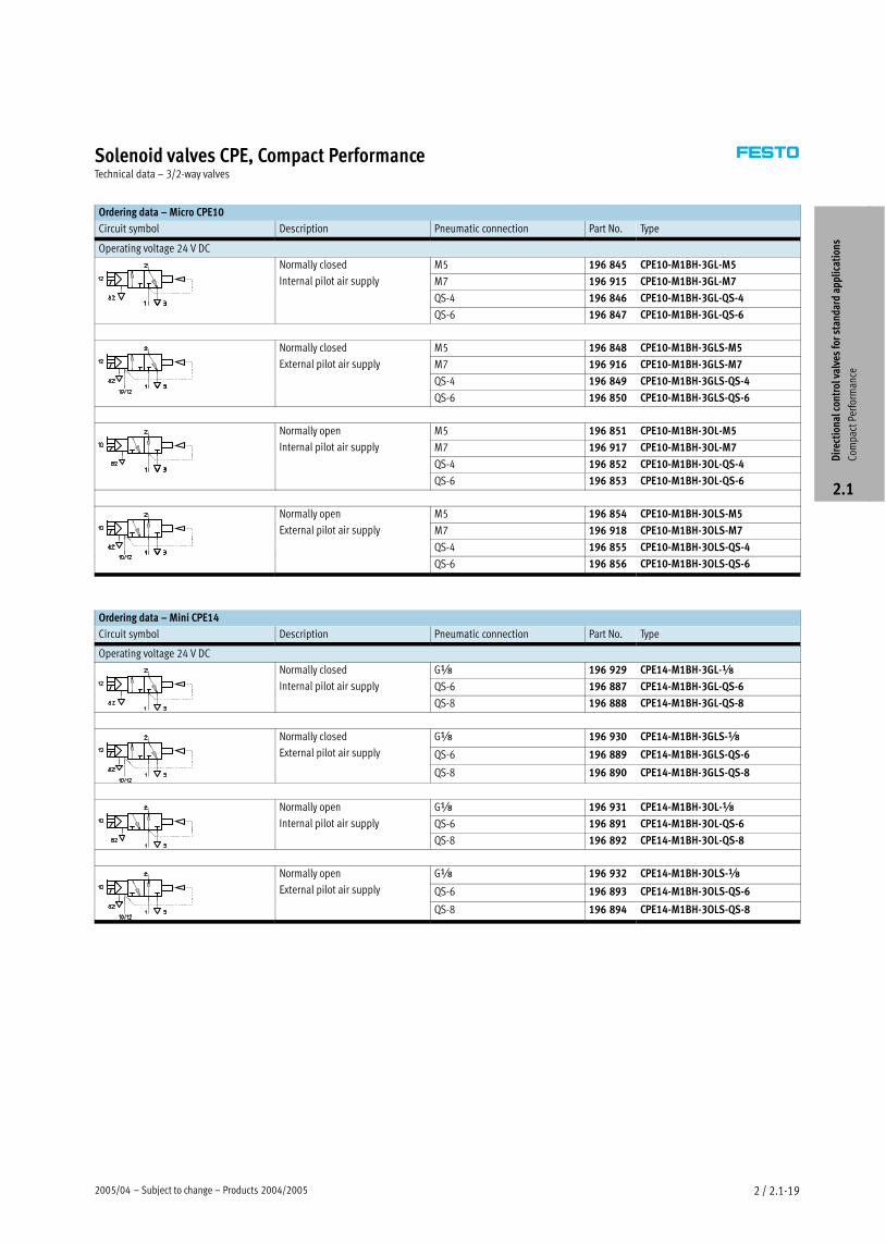
Ordering data – Micro CPE10
Circuit symbol Description Pneumatic connection Part No. Type
Operating voltage 24 V DC
Normally closed M5 196 845 CPE10−M1BH−3GL−M5y
Internal pilot air supply M7 196 915 CPE10−M1BH−3GL−M7p pp y
QS−4 196 846 CPE10−M1BH−3GL−QS−4
QS−6 196 847 CPE10−M1BH−3GL−QS−6
Normally closed M5 196 848 CPE10−M1BH−3GLS−M5y
External pilot air supply M7 196 916 CPE10−M1BH−3GLS−M7p pp y
QS−4 196 849 CPE10−M1BH−3GLS−QS−4
QS−6 196 850 CPE10−M1BH−3GLS−QS−6
Normally open M5 196 851 CPE10−M1BH−3OL−M5y p
Internal pilot air supply M7 196 917 CPE10−M1BH−3OL−M7p pp y
QS−4 196 852 CPE10−M1BH−3OL−QS−4
QS−6 196 853 CPE10−M1BH−3OL−QS−6
Normally open M5 196 854 CPE10−M1BH−3OLS−M5y p
External pilot air supply M7 196 918 CPE10−M1BH−3OLS−M7p pp y
QS−4 196 855 CPE10−M1BH−3OLS−QS−4
QS−6 196 856 CPE10−M1BH−3OLS−QS−6
Ordering data – Mini CPE14
Circuit symbol Description Pneumatic connection Part No. Type
Operating voltage 24 V DC
Normally closed Gx 196 929 CPE14−M1BH−3GL−xy
Internal pilot air supply QS−6 196 887 CPE14−M1BH−3GL−QS−6p pp y
QS−8 196 888 CPE14−M1BH−3GL−QS−8
Normally closed Gx 196 930 CPE14−M1BH−3GLS−xy
External pilot air supply QS−6 196 889 CPE14−M1BH−3GLS−QS−6
QS−8 196 890 CPE14−M1BH−3GLS−QS−8
Normally open Gx 196 931 CPE14−M1BH−3OL−xy p
Internal pilot air supply QS−6 196 891 CPE14−M1BH−3OL−QS−6p pp y
QS−8 196 892 CPE14−M1BH−3OL−QS−8
Normally open Gx 196 932 CPE14−M1BH−3OLS−xy p
External pilot air supply QS−6 196 893 CPE14−M1BH−3OLS−QS−6
QS−8 196 894 CPE14−M1BH−3OLS−QS−8
Dir
ecti
onal
con
trol
val
ves
for
stan
dard
app
lica
tion
s
Com
pact
Per
form
ance
2.1
Products 2004/2005 – Subject to change – 2005/042 / 2.1−20
Solenoid valves CPE, Compact PerformanceTechnical data – 3/2−way valves
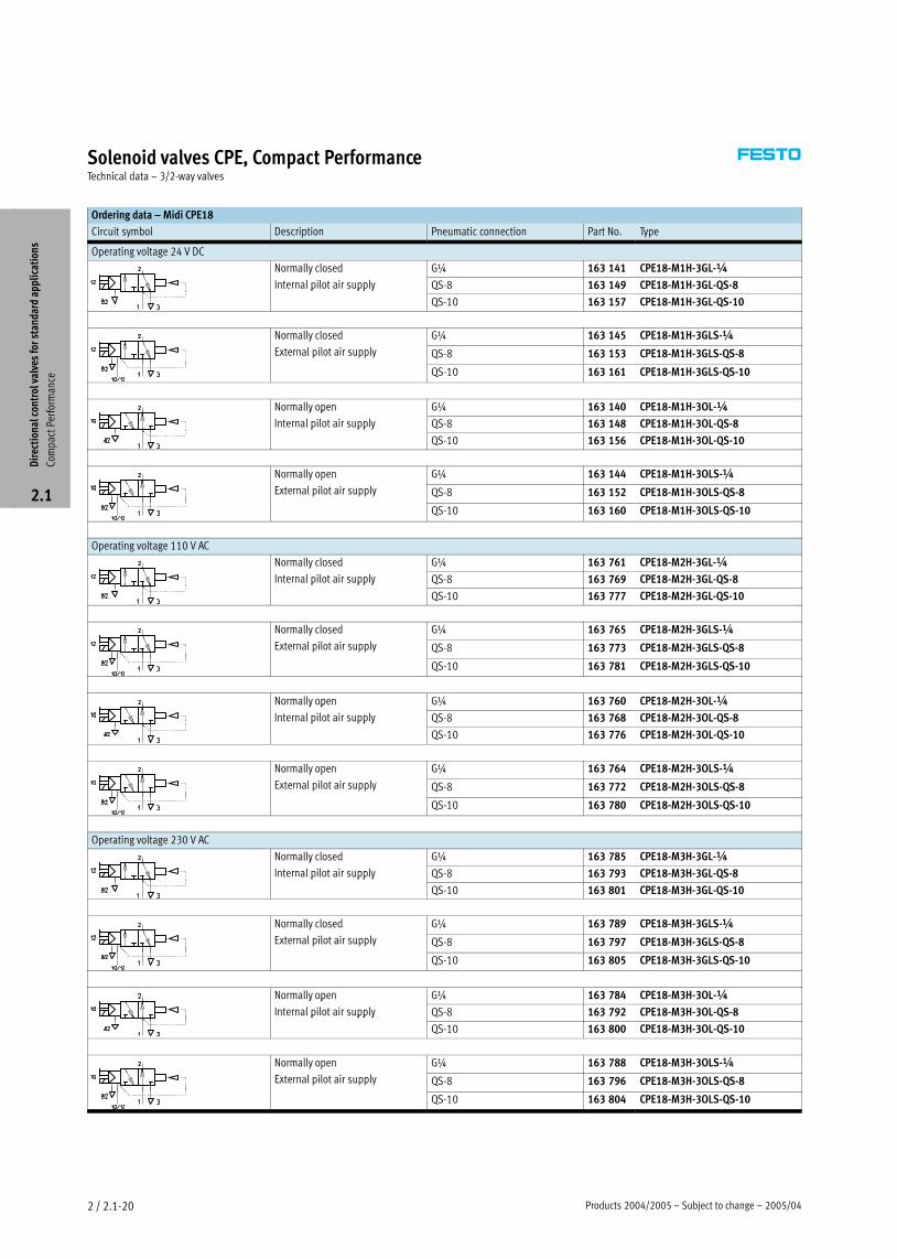
Ordering data – Midi CPE18
Circuit symbol Description Pneumatic connection Part No. Type
Operating voltage 24 V DC
Normally closed G¼ 163 141 CPE18−M1H−3GL−¼y
Internal pilot air supply QS−8 163 149 CPE18−M1H−3GL−QS−8p pp y
QS−10 163 157 CPE18−M1H−3GL−QS−10
Normally closed G¼ 163 145 CPE18−M1H−3GLS−¼y
External pilot air supply QS−8 163 153 CPE18−M1H−3GLS−QS−8
QS−10 163 161 CPE18−M1H−3GLS−QS−10
Normally open G¼ 163 140 CPE18−M1H−3OL−¼y p
Internal pilot air supply QS−8 163 148 CPE18−M1H−3OL−QS−8p pp y
QS−10 163 156 CPE18−M1H−3OL−QS−10
Normally open G¼ 163 144 CPE18−M1H−3OLS−¼y p
External pilot air supply QS−8 163 152 CPE18−M1H−3OLS−QS−8
QS−10 163 160 CPE18−M1H−3OLS−QS−10
Operating voltage 110 V AC
Normally closed G¼ 163 761 CPE18−M2H−3GL−¼y
Internal pilot air supply QS−8 163 769 CPE18−M2H−3GL−QS−8p pp y
QS−10 163 777 CPE18−M2H−3GL−QS−10
Normally closed G¼ 163 765 CPE18−M2H−3GLS−¼y
External pilot air supply QS−8 163 773 CPE18−M2H−3GLS−QS−8
QS−10 163 781 CPE18−M2H−3GLS−QS−10
Normally open G¼ 163 760 CPE18−M2H−3OL−¼y p
Internal pilot air supply QS−8 163 768 CPE18−M2H−3OL−QS−8p pp y
QS−10 163 776 CPE18−M2H−3OL−QS−10
Normally open G¼ 163 764 CPE18−M2H−3OLS−¼y p
External pilot air supply QS−8 163 772 CPE18−M2H−3OLS−QS−8
QS−10 163 780 CPE18−M2H−3OLS−QS−10
Operating voltage 230 V AC
Normally closed G¼ 163 785 CPE18−M3H−3GL−¼y
Internal pilot air supply QS−8 163 793 CPE18−M3H−3GL−QS−8p pp y
QS−10 163 801 CPE18−M3H−3GL−QS−10
Normally closed G¼ 163 789 CPE18−M3H−3GLS−¼y
External pilot air supply QS−8 163 797 CPE18−M3H−3GLS−QS−8
QS−10 163 805 CPE18−M3H−3GLS−QS−10
Normally open G¼ 163 784 CPE18−M3H−3OL−¼y p
Internal pilot air supply QS−8 163 792 CPE18−M3H−3OL−QS−8p pp y
QS−10 163 800 CPE18−M3H−3OL−QS−10
Normally open G¼ 163 788 CPE18−M3H−3OLS−¼y p
External pilot air supply QS−8 163 796 CPE18−M3H−3OLS−QS−8
QS−10 163 804 CPE18−M3H−3OLS−QS−10
Dir
ecti
onal
con
trol
val
ves
for
stan
dard
app
lica
tion
s
Com
pact
Per
form
ance
2.1
2005/04 – Subject to change – Products 2004/2005 2 / 2.1−21
Solenoid valves CPE, Compact PerformanceTechnical data – 3/2−way valves
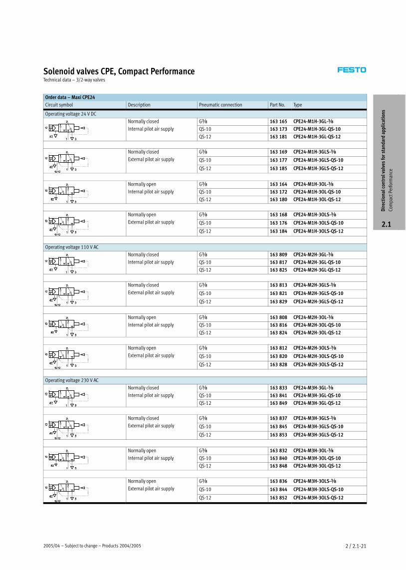
Order data – Maxi CPE24
Circuit symbol Description Pneumatic connection Part No. Type
Operating voltage 24 V DC
Normally closed Gy 163 165 CPE24−M1H−3GL−yy
Internal pilot air supply QS−10 163 173 CPE24−M1H−3GL−QS−10p pp y
QS−12 163 181 CPE24−M1H−3GL−QS−12
Normally closed Gy 163 169 CPE24−M1H−3GLS−yy
External pilot air supply QS−10 163 177 CPE24−M1H−3GLS−QS−10
QS−12 163 185 CPE24−M1H−3GLS−QS−12
Normally open Gy 163 164 CPE24−M1H−3OL−yy p
Internal pilot air supply QS−10 163 172 CPE24−M1H−3OL−QS−10p pp y
QS−12 163 180 CPE24−M1H−3OL−QS−12
Normally open Gy 163 168 CPE24−M1H−3OLS−yy p
External pilot air supply QS−10 163 176 CPE24−M1H−3OLS−QS−10
QS−12 163 184 CPE24−M1H−3OLS−QS−12
Operating voltage 110 V AC
Normally closed Gy 163 809 CPE24−M2H−3GL−yy
Internal pilot air supply QS−10 163 817 CPE24−M2H−3GL−QS−10p pp y
QS−12 163 825 CPE24−M2H−3GL−QS−12
Normally closed Gy 163 813 CPE24−M2H−3GLS−yy
External pilot air supply QS−10 163 821 CPE24−M2H−3GLS−QS−10
QS−12 163 829 CPE24−M2H−3GLS−QS−12
Normally open Gy 163 808 CPE24−M2H−3OL−yy p
Internal pilot air supply QS−10 163 816 CPE24−M2H−3OL−QS−10p pp y
QS−12 163 824 CPE24−M2H−3OL−QS−12
Normally open Gy 163 812 CPE24−M2H−3OLS−yy p
External pilot air supply QS−10 163 820 CPE24−M2H−3OLS−QS−10
QS−12 163 828 CPE24−M2H−3OLS−QS−12
Operating voltage 230 V AC
Normally closed Gy 163 833 CPE24−M3H−3GL−yy
Internal pilot air supply QS−10 163 841 CPE24−M3H−3GL−QS−10p pp y
QS−12 163 849 CPE24−M3H−3GL−QS−12
Normally closed Gy 163 837 CPE24−M3H−3GLS−yy
External pilot air supply QS−10 163 845 CPE24−M3H−3GLS−QS−10
QS−12 163 853 CPE24−M3H−3GLS−QS−12
Normally open Gy 163 832 CPE24−M3H−3OL−yy p
Internal pilot air supply QS−10 163 840 CPE24−M3H−3OL−QS−10p pp y
QS−12 163 848 CPE24−M3H−3OL−QS−12
Normally open Gy 163 836 CPE24−M3H−3OLS−yy p
External pilot air supply QS−10 163 844 CPE24−M3H−3OLS−QS−10
QS−12 163 852 CPE24−M3H−3OLS−QS−12
Dir
ecti
onal
con
trol
val
ves
for
stan
dard
app
lica
tion
s
Com
pact
Per
form
ance
2.1
Products 2004/2005 – Subject to change – 2005/042 / 2.1−22
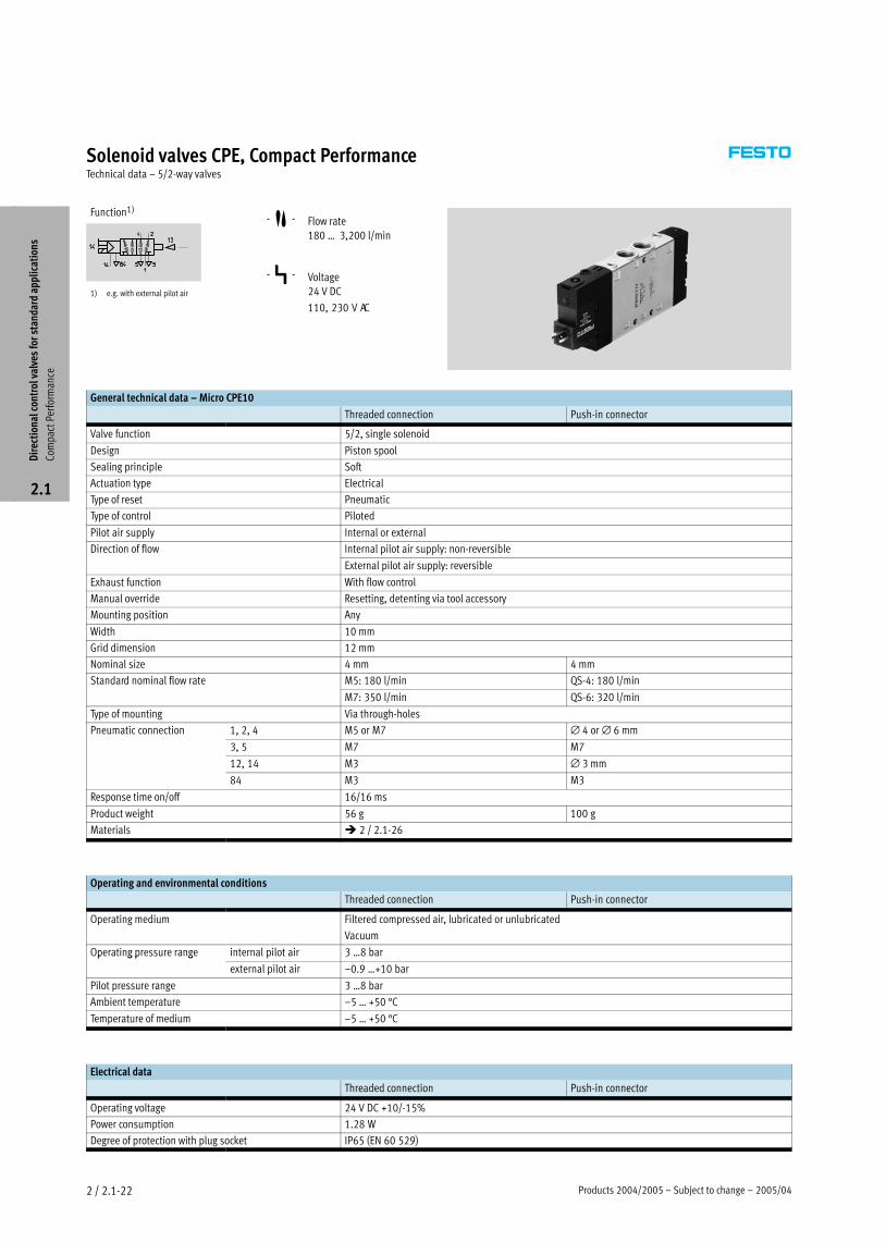
Solenoid valves CPE, Compact PerformanceTechnical data – 5/2−way valves
Function1)
1) e.g. with external pilot air
−M− Flow rate
180 Ī 3,200 l/min
−P− Voltage
24 V DC
110, 230 V AC
General technical data – Micro CPE10
Threaded connection Push−in connector
Valve function 5/2, single solenoid
Design Piston spool
Sealing principle Soft
Actuation type Electrical
Type of reset Pneumatic
Type of control Piloted
Pilot air supply Internal or external
Direction of flow Internal pilot air supply: non−reversible
External pilot air supply: reversible
Exhaust function With flow control
Manual override Resetting, detenting via tool accessory
Mounting position Any
Width 10 mm
Grid dimension 12 mm
Nominal size 4 mm 4 mm
Standard nominal flow rate M5: 180 l/min QS−4: 180 l/min
M7: 350 l/min QS−6: 320 l/min
Type of mounting Via through−holes
Pneumatic connection 1, 2, 4 M5 or M7 ∅ 4 or ∅ 6 mm
3, 5 M7 M7
12, 14 M3 ∅ 3 mm
84 M3 M3
Response time on/off 16/16 ms
Product weight 56 g 100 g
Materials � 2 / 2.1−26
Operating and environmental conditions
Threaded connection Push−in connector
Operating medium Filtered compressed air, lubricated or unlubricated
Vacuum
Operating pressure range internal pilot air 3 Ī8 barp g p g
external pilot air –0.9 Ī+10 bar
Pilot pressure range 3 Ī8 bar
Ambient temperature –5 Ī +50 °C
Temperature of medium –5 Ī +50 °C
Electrical data
Threaded connection Push−in connector
Operating voltage 24 V DC +10/−15%
Power consumption 1.28 W
Degree of protection with plug socket IP65 (EN 60 529)
Dir
ecti
onal
con
trol
val
ves
for
stan
dard
app
lica
tion
s
Com
pact
Per
form
ance
2.1

2005/04 – Subject to change – Products 2004/2005 2 / 2.1−23
Solenoid valves CPE, Compact PerformanceTechnical data – 5/2−way valves
General technical data – Mini CPE14
Threaded connection Push−in connector
Valve function 5/2, single solenoid
Design Piston spool
Sealing principle Soft
Actuation type Electrical
Type of reset Pneumatic
Type of control Piloted
Pilot air supply Internal or external
Direction of flow Internal pilot air supply: non−reversible
External pilot air supply: reversible
Exhaust function With flow control
Manual override Resetting, detenting via tool accessory
Mounting position Any
Width 14 mm
Grid dimension 16 mm
Nominal size 6 mm 6 mm
Standard nominal flow rate Gx: 800 l/min QS−6: 400 l/minx /
QS−8: 680 l/min
Type of mounting Via through−holes
Pneumatic connection 1, 2, 4 Gx ∅ 6 or ∅ 8 mm
3, 5 Gx Gx
12, 14 M3 ∅ 3 mm
84 M3 M3
Response time on/off 24/32 ms
Product weight 95 g 143 g
Materials � 2 / 2.1−26
Operating and environmental conditions
Threaded connection Push−in connector
Operating medium Filtered compressed air, lubricated or unlubricated
Vacuum
Operating pressure range internal pilot air 3 Ī8 barp g p g
external pilot air –0.9 Ī+10 bar
Pilot pressure range 3 Ī8 bar
Ambient temperature –5 Ī +50 °C
Temperature of medium –5 Ī +50 °C
Electrical data
Threaded connection Push−in connector
Operating voltage 24 V DC +10/−15%
Power consumption 1.28 W
Degree of protection with plug socket IP65 (EN 60 529)
Dir
ecti
onal
con
trol
val
ves
for
stan
dard
app
lica
tion
s
Com
pact
Per
form
ance
2.1

Products 2004/2005 – Subject to change – 2005/042 / 2.1−24
Solenoid valves CPE, Compact PerformanceTechnical data – 5/2−way valves
General technical data – Midi CPE18
Threaded connection Push−in connector
Valve function 5/2, single solenoid
Design Piston spool
Sealing principle Soft
Actuation type Electrical
Type of reset Pneumatic
Type of control Piloted
Pilot air supply Internal or external
Direction of flow Internal pilot air supply: non−reversible
External pilot air supply: reversible
Exhaust function With flow control
Manual override Resetting, detenting via tool accessory
Mounting position Any
Width 18 mm
Grid dimension 20 mm
Nominal size 8 mm 8 mm
Standard nominal flow rate G¼: 1,500 l/min QS−8: 850 l/min¼ ,5 /
QS−10: 1,000 l/min
Type of mounting Via through−holes
Pneumatic connection 1, 2, 4 G¼ ∅ 8 or ∅ 10 mm
3, 5 G¼ G¼
12, 14 M5 ∅ 4 mm
84 M5 M5
Response time on/off 26/20 ms
Product weight 220 g
Materials � 2 / 2.1−26
Operating and environmental conditions
Threaded connection Push−in connector
Operating medium Filtered compressed air, lubricated or unlubricated
Vacuum
Operating pressure range internal pilot air 2.5 Ī10 barp g p g
external pilot air –0.9 Ī+10 bar
Pilot pressure range 2.5 Ī10 bar
Ambient temperature –5 Ī +50 °C
Temperature of medium –5 Ī +50 °C
Electrical data
Threaded connection Push−in connector
Operating voltage M1H 24 V DC +10/−15%p g g
M2H 110 V AC ±10% at 50 Ī 60 Hz
M3H 230 V AC ±10% at 50 Ī 60 Hz
Power consumption M1H 1.5 Wp
M2H, M3H Pull: 3 VA, 3
Hold: 2.4 VA
Degree of protection with plug socket IP65 (EN 60 529)
Dir
ecti
onal
con
trol
val
ves
for
stan
dard
app
lica
tion
s
Com
pact
Per
form
ance
2.1

2005/04 – Subject to change – Products 2004/2005 2 / 2.1−25
Solenoid valves CPE, Compact PerformanceTechnical data – 5/2−way valves
General technical data – Maxi CPE24
Threaded connection Push−in connector
Valve function 5/2, single solenoid
Design Piston spool
Sealing principle Soft
Actuation type Electrical
Type of reset Pneumatic
Type of control Piloted
Pilot air supply Internal or external
Direction of flow Internal pilot air supply: non−reversible
External pilot air supply: reversible
Exhaust function With flow control
Manual override Resetting, detenting via tool accessory
Mounting position Any
Width 24 mm
Nominal size 11 mm 11 mm
Standard nominal flow rate Gy: 2, 900 l/min QS−10: 1,250 l/miny , 9 /
QS−12: 1,650 l/min
Type of mounting Via through−holes
Pneumatic connection 1, 2, 4 Gy ∅ 10 or ∅ 12 mm
3, 5 Gy Gy
12, 14 M5 ∅ 6 mm
84 M5 M5
Response time on/off 40/50 ms
Product weight 360 g
Materials � 2 / 2.1−26
Operating and environmental conditions
Threaded connection Push−in connector
Operating medium Filtered compressed air, lubricated or unlubricated
Vacuum
Operating pressure range internal pilot air 2.5 Ī10 barp g p g
external pilot air –0.9 Ī+10 bar
Pilot pressure range 2.5 Ī10 bar
Ambient temperature –5 Ī +50 °C
Temperature of medium –5 Ī +50 °C
Electrical data
Threaded connection Push−in connector
Operating voltage M1H 24 V DC +10/−15%p g g
M2H 110 V AC ±10% at 50 Ī 60 Hz
M3H 230 V AC ±10% at 50 Ī 60 Hz
Power consumption M1H 1.5 Wp
M2H, M3H Pull: 3 VA, 3
Hold: 2.4 VA
Degree of protection with plug socket IP65 (EN 60 529)
Dir
ecti
onal
con
trol
val
ves
for
stan
dard
app
lica
tion
s
Com
pact
Per
form
ance
2.1
Products 2004/2005 – Subject to change – 2005/042 / 2.1−26
Solenoid valves CPE, Compact PerformanceTechnical data – 5/2−way valves
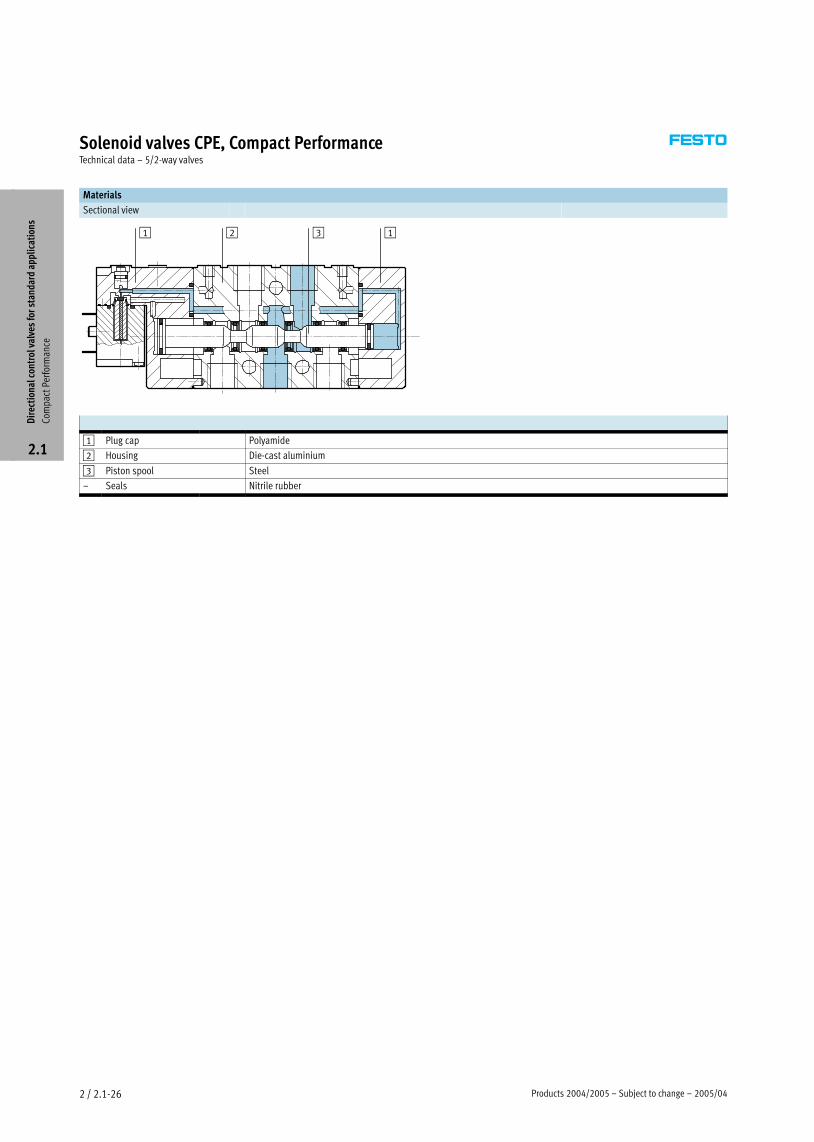
Materials
Sectional view
1 2 3 1
1 Plug cap Polyamide
2 Housing Die−cast aluminium
3 Piston spool Steel
– Seals Nitrile rubber
Dir
ecti
onal
con
trol
val
ves
for
stan
dard
app
lica
tion
s
Com
pact
Per
form
ance
2.1
2005/04 – Subject to change – Products 2004/2005 2 / 2.1−27
Solenoid valves CPE, Compact PerformanceTechnical data – 5/2−way valves
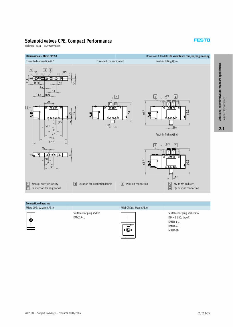
Dimensions – Micro CPE10 Download CAD data � www.festo.com/en/engineering
Threaded connection M7 Push−in fitting QS−4Threaded connection M5
Push−in fitting QS−6
1 Manual override facility
2 Connection for plug socket
3 Location for inscription labels 4 Pilot air connection 5 M7 to M5 reducer
6 QS push−in connection
Connection diagrams
Micro CPE10, Mini CPE14 Midi CPE18, Maxi CPE24
Suitable for plug socket
KMYZ−9−...
Suitable for plug sockets to
DIN 43 650, type C
KMEB−1−...
KMEB−2−...
MSSD−EB
Dir
ecti
onal
con
trol
val
ves
for
stan
dard
app
lica
tion
s
Com
pact
Per
form
ance
2.1
Products 2004/2005 – Subject to change – 2005/042 / 2.1−28
Solenoid valves CPE, Compact PerformanceTechnical data – 5/2−way valves
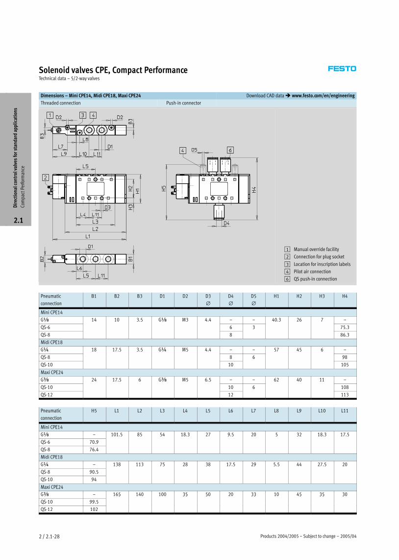
Dimensions – Mini CPE14, Midi CPE18, Maxi CPE24 Download CAD data � www.festo.com/en/engineering
Threaded connection Push−in connector
1 Manual override facility
2 Connection for plug socket
3 Location for inscription labels
4 Pilot air connection
6 QS push−in connection
Pneumatic
connection
B1 B2 B3 D1 D2 D3
∅D4
∅D5
∅H1 H2 H3 H4
Mini CPE14
Gx 14 10 3.5 Gx M3 4.4 – – 40.3 26 7 –
QS−6
3 5
6 3
3 7
75.3
QS−8 8
3
86.3
Midi CPE18
G¼ 18 17.5 3.5 G¼ M5 4.4 – – 57 45 6 –
QS−8
7 5 3 5
8 6
57 5
98
QS−10 10 105
Maxi CPE24
Gy 24 17.5 6 Gy M5 6.5 – – 62 40 11 –
QS−10
7 5 5
10 6 108
QS−12 12 113
Pneumatic
connection
H5 L1 L2 L3 L4 L5 L6 L7 L8 L9 L10 L11
Mini CPE14
Gx – 101.5 85 54 18.3 27 9.5 20 5 32 18.3 17.5
QS−6 70.9
5 5 5 3 7 9 5 5 3 3 7 5
QS−8 76.4
Midi CPE18
G¼ – 138 113 75 28 38 17.5 29 5.5 44 27.5 20
QS−8 90.5
3 3 75 3 7 5 9 5 5 7 5
QS−10 94
Maxi CPE24
Gy – 165 140 100 35 50 20 33 10 45 35 30
QS−10 99.5
5 35 5 33 5 35 3
QS−12 102
Dir
ecti
onal
con
trol
val
ves
for
stan
dard
app
lica
tion
s
Com
pact
Per
form
ance
2.1
2005/04 – Subject to change – Products 2004/2005 2 / 2.1−29
Solenoid valves CPE, Compact PerformanceTechnical data – 5/2−way valves
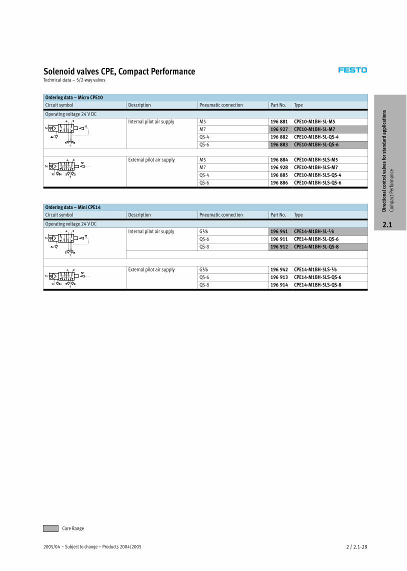
Ordering data – Micro CPE10
Circuit symbol Description Pneumatic connection Part No. Type
Operating voltage 24 V DC
Internal pilot air supply M5 196 881 CPE10−M1BH−5L−M5p pp y
M7 196 927 CPE10−M1BH−5L−M7
QS−4 196 882 CPE10−M1BH−5L−QS−4
QS−6 196 883 CPE10−M1BH−5L−QS−6
External pilot air supply M5 196 884 CPE10−M1BH−5LS−M5p pp y
M7 196 928 CPE10−M1BH−5LS−M7
QS−4 196 885 CPE10−M1BH−5LS−QS−4
QS−6 196 886 CPE10−M1BH−5LS−QS−6
Ordering data – Mini CPE14
Circuit symbol Description Pneumatic connection Part No. Type
Operating voltage 24 V DC
Internal pilot air supply Gx 196 941 CPE14−M1BH−5L−xp pp y
QS−6 196 911 CPE14−M1BH−5L−QS−6
QS−8 196 912 CPE14−M1BH−5L−QS−8
External pilot air supply Gx 196 942 CPE14−M1BH−5LS−xp pp y
QS−6 196 913 CPE14−M1BH−5LS−QS−6
QS−8 196 914 CPE14−M1BH−5LS−QS−8
Dir
ecti
onal
con
trol
val
ves
for
stan
dard
app
lica
tion
s
Com
pact
Per
form
ance
2.1
Core Range
Products 2004/2005 – Subject to change – 2005/042 / 2.1−30
Solenoid valves CPE, Compact PerformanceTechnical data – 5/2−way valves
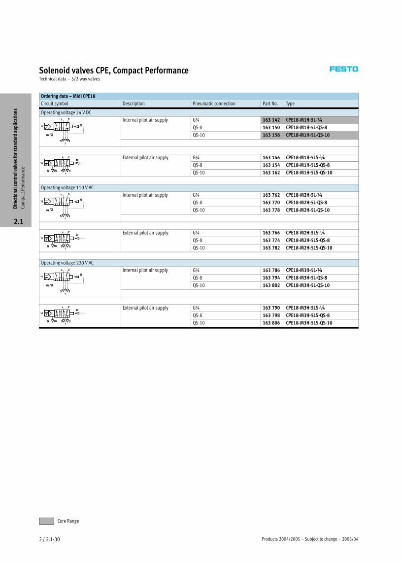
Ordering data – Midi CPE18
Circuit symbol Description Pneumatic connection Part No. Type
Operating voltage 24 V DC
Internal pilot air supply G¼ 163 142 CPE18−M1H−5L−¼p pp y
QS−8 163 150 CPE18−M1H−5L−QS−8
QS−10 163 158 CPE18−M1H−5L−QS−10
External pilot air supply G¼ 163 146 CPE18−M1H−5LS−¼p pp y
QS−8 163 154 CPE18−M1H−5LS−QS−8
QS−10 163 162 CPE18−M1H−5LS−QS−10
Operating voltage 110 V AC
Internal pilot air supply G¼ 163 762 CPE18−M2H−5L−¼p pp y
QS−8 163 770 CPE18−M2H−5L−QS−8
QS−10 163 778 CPE18−M2H−5L−QS−10
External pilot air supply G¼ 163 766 CPE18−M2H−5LS−¼p pp y
QS−8 163 774 CPE18−M2H−5LS−QS−8
QS−10 163 782 CPE18−M2H−5LS−QS−10
Operating voltage 230 V AC
Internal pilot air supply G¼ 163 786 CPE18−M3H−5L−¼p pp y
QS−8 163 794 CPE18−M3H−5L−QS−8
QS−10 163 802 CPE18−M3H−5L−QS−10
External pilot air supply G¼ 163 790 CPE18−M3H−5LS−¼p pp y
QS−8 163 798 CPE18−M3H−5LS−QS−8
QS−10 163 806 CPE18−M3H−5LS−QS−10
Dir
ecti
onal
con
trol
val
ves
for
stan
dard
app
lica
tion
s
Com
pact
Per
form
ance
2.1
Core Range
2005/04 – Subject to change – Products 2004/2005 2 / 2.1−31
Solenoid valves CPE, Compact PerformanceTechnical data – 5/2−way valves
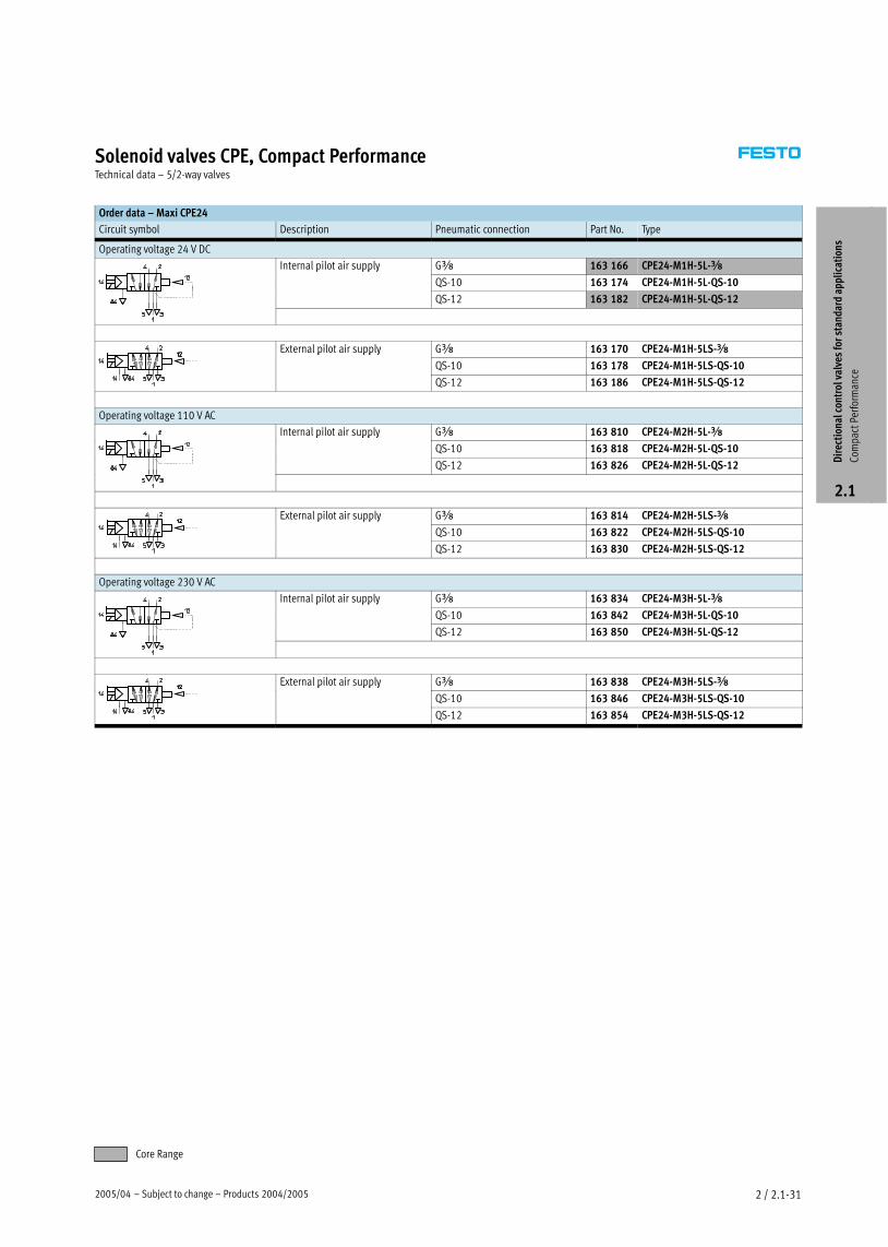
Order data – Maxi CPE24
Circuit symbol Description Pneumatic connection Part No. Type
Operating voltage 24 V DC
Internal pilot air supply Gy 163 166 CPE24−M1H−5L−yp pp y
QS−10 163 174 CPE24−M1H−5L−QS−10
QS−12 163 182 CPE24−M1H−5L−QS−12
External pilot air supply Gy 163 170 CPE24−M1H−5LS−yp pp y
QS−10 163 178 CPE24−M1H−5LS−QS−10
QS−12 163 186 CPE24−M1H−5LS−QS−12
Operating voltage 110 V AC
Internal pilot air supply Gy 163 810 CPE24−M2H−5L−yp pp y
QS−10 163 818 CPE24−M2H−5L−QS−10
QS−12 163 826 CPE24−M2H−5L−QS−12
External pilot air supply Gy 163 814 CPE24−M2H−5LS−yp pp y
QS−10 163 822 CPE24−M2H−5LS−QS−10
QS−12 163 830 CPE24−M2H−5LS−QS−12
Operating voltage 230 V AC
Internal pilot air supply Gy 163 834 CPE24−M3H−5L−yp pp y
QS−10 163 842 CPE24−M3H−5L−QS−10
QS−12 163 850 CPE24−M3H−5L−QS−12
External pilot air supply Gy 163 838 CPE24−M3H−5LS−yp pp y
QS−10 163 846 CPE24−M3H−5LS−QS−10
QS−12 163 854 CPE24−M3H−5LS−QS−12
Dir
ecti
onal
con
trol
val
ves
for
stan
dard
app
lica
tion
s
Com
pact
Per
form
ance
2.1
Core Range
Products 2004/2005 – Subject to change – 2005/042 / 2.1−32
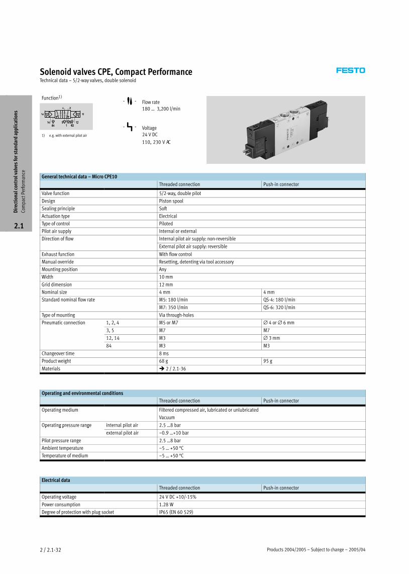
Solenoid valves CPE, Compact PerformanceTechnical data – 5/2−way valves, double solenoid
Function1)
1) e.g. with external pilot air
−M− Flow rate
180 Ī 3,200 l/min
−P− Voltage
24 V DC
110, 230 V AC
General technical data – Micro CPE10
Threaded connection Push−in connector
Valve function 5/2−way, double pilot
Design Piston spool
Sealing principle Soft
Actuation type Electrical
Type of control Piloted
Pilot air supply Internal or external
Direction of flow Internal pilot air supply: non−reversible
External pilot air supply: reversible
Exhaust function With flow control
Manual override Resetting, detenting via tool accessory
Mounting position Any
Width 10 mm
Grid dimension 12 mm
Nominal size 4 mm 4 mm
Standard nominal flow rate M5: 180 l/min QS−4: 180 l/min
M7: 350 l/min QS−6: 320 l/min
Type of mounting Via through−holes
Pneumatic connection 1, 2, 4 M5 or M7 ∅ 4 or ∅ 6 mm
3, 5 M7 M7
12, 14 M3 ∅ 3 mm
84 M3 M3
Changeover time 8 ms
Product weight 68 g 95 g
Materials � 2 / 2.1−36
Operating and environmental conditions
Threaded connection Push−in connector
Operating medium Filtered compressed air, lubricated or unlubricated
Vacuum
Operating pressure range internal pilot air 2.5 Ī8 barp g p g
external pilot air –0.9 Ī+10 bar
Pilot pressure range 2.5 Ī8 bar
Ambient temperature –5 Ī +50 °C
Temperature of medium –5 Ī +50 °C
Electrical data
Threaded connection Push−in connector
Operating voltage 24 V DC +10/−15%
Power consumption 1.28 W
Degree of protection with plug socket IP65 (EN 60 529)
Dir
ecti
onal
con
trol
val
ves
for
stan
dard
app
lica
tion
s
Com
pact
Per
form
ance
2.1

2005/04 – Subject to change – Products 2004/2005 2 / 2.1−33
Solenoid valves CPE, Compact PerformanceTechnical data – 5/2−way valves, double solenoid
General technical data – Mini CPE14
Threaded connection Push−in connector
Valve function 5/2−way, double pilot
Design Piston spool
Sealing principle Soft
Actuation type Electrical
Type of control Piloted
Pilot air supply Internal or external
Direction of flow Internal pilot air supply: non−reversible
External pilot air supply: reversible
Exhaust function With flow control
Manual override Resetting, detenting via tool accessory
Mounting position Any
Width 14 mm
Grid dimension 16 mm
Nominal size 6 mm 6 mm
Standard nominal flow rate Gx: 800 l/min QS−6: 400 l/minx /
QS−8: 680 l/min
Type of mounting Via through−holes
Pneumatic connection 1, 2, 4 Gx ∅ 6 or ∅ 8 mm
3, 5 Gx Gx
12, 14 M3 ∅ 3 mm
84 M3 M3
Changeover time 12 ms
Product weight 115 g 144 g
Materials � 2 / 2.1−36
Operating and environmental conditions
Threaded connection Push−in connector
Operating medium Filtered compressed air, lubricated or unlubricated
Vacuum
Operating pressure range internal pilot air 2 Ī8 barp g p g
external pilot air –0.9 Ī+10 bar
Pilot pressure range 2 Ī8 bar
Ambient temperature –5 Ī +50 °C
Temperature of medium –5 Ī +50 °C
Electrical data
Threaded connection Push−in connector
Operating voltage 24 V DC +10/−15%
Power consumption 1.28 W
Degree of protection with plug socket IP65 (EN 60 529)
Dir
ecti
onal
con
trol
val
ves
for
stan
dard
app
lica
tion
s
Com
pact
Per
form
ance
2.1
Products 2004/2005 – Subject to change – 2005/042 / 2.1−34
Solenoid valves CPE, Compact PerformanceTechnical data – 5/2−way valves, double solenoid
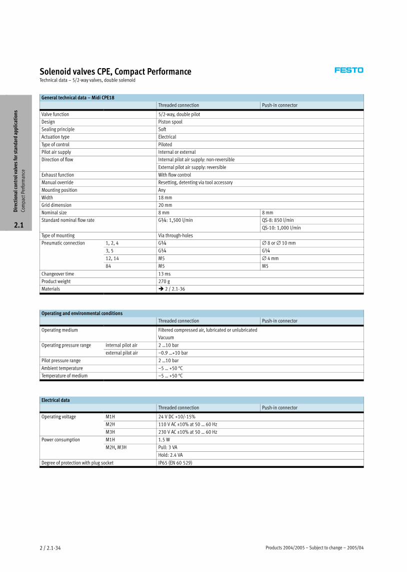
General technical data – Midi CPE18
Threaded connection Push−in connector
Valve function 5/2−way, double pilot
Design Piston spool
Sealing principle Soft
Actuation type Electrical
Type of control Piloted
Pilot air supply Internal or external
Direction of flow Internal pilot air supply: non−reversible
External pilot air supply: reversible
Exhaust function With flow control
Manual override Resetting, detenting via tool accessory
Mounting position Any
Width 18 mm
Grid dimension 20 mm
Nominal size 8 mm 8 mm
Standard nominal flow rate G¼: 1,500 l/min QS−8: 850 l/min¼ ,5 /
QS−10: 1,000 l/min
Type of mounting Via through−holes
Pneumatic connection 1, 2, 4 G¼ ∅ 8 or ∅ 10 mm
3, 5 G¼ G¼
12, 14 M5 ∅ 4 mm
84 M5 M5
Changeover time 13 ms
Product weight 270 g
Materials � 2 / 2.1−36
Operating and environmental conditions
Threaded connection Push−in connector
Operating medium Filtered compressed air, lubricated or unlubricated
Vacuum
Operating pressure range internal pilot air 2 Ī10 barp g p g
external pilot air –0.9 Ī+10 bar
Pilot pressure range 2 Ī10 bar
Ambient temperature –5 Ī +50 °C
Temperature of medium –5 Ī +50 °C
Electrical data
Threaded connection Push−in connector
Operating voltage M1H 24 V DC +10/−15%p g g
M2H 110 V AC ±10% at 50 Ī 60 Hz
M3H 230 V AC ±10% at 50 Ī 60 Hz
Power consumption M1H 1.5 Wp
M2H, M3H Pull: 3 VA, 3
Hold: 2.4 VA
Degree of protection with plug socket IP65 (EN 60 529)
Dir
ecti
onal
con
trol
val
ves
for
stan
dard
app
lica
tion
s
Com
pact
Per
form
ance
2.1
2005/04 – Subject to change – Products 2004/2005 2 / 2.1−35
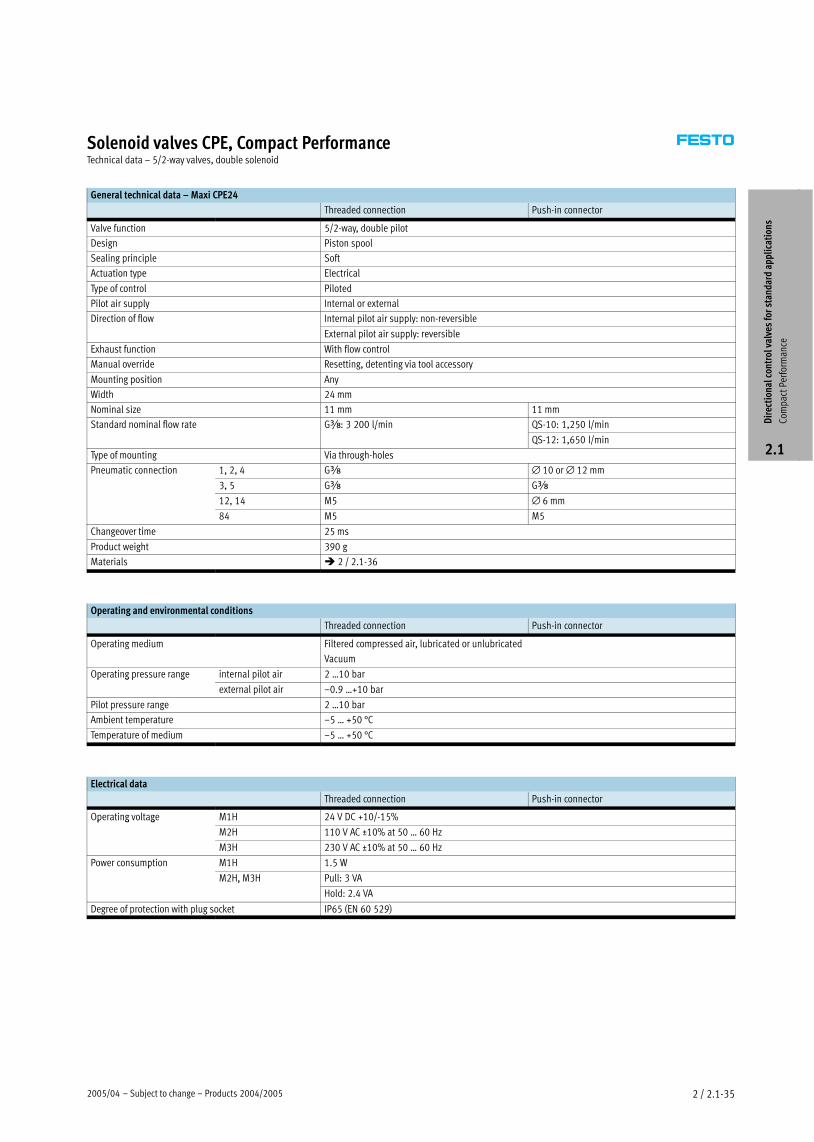
Solenoid valves CPE, Compact PerformanceTechnical data – 5/2−way valves, double solenoid
General technical data – Maxi CPE24
Threaded connection Push−in connector
Valve function 5/2−way, double pilot
Design Piston spool
Sealing principle Soft
Actuation type Electrical
Type of control Piloted
Pilot air supply Internal or external
Direction of flow Internal pilot air supply: non−reversible
External pilot air supply: reversible
Exhaust function With flow control
Manual override Resetting, detenting via tool accessory
Mounting position Any
Width 24 mm
Nominal size 11 mm 11 mm
Standard nominal flow rate Gy: 3 200 l/min QS−10: 1,250 l/miny 3 /
QS−12: 1,650 l/min
Type of mounting Via through−holes
Pneumatic connection 1, 2, 4 Gy ∅ 10 or ∅ 12 mm
3, 5 Gy Gy
12, 14 M5 ∅ 6 mm
84 M5 M5
Changeover time 25 ms
Product weight 390 g
Materials � 2 / 2.1−36
Operating and environmental conditions
Threaded connection Push−in connector
Operating medium Filtered compressed air, lubricated or unlubricated
Vacuum
Operating pressure range internal pilot air 2 Ī10 barp g p g
external pilot air –0.9 Ī+10 bar
Pilot pressure range 2 Ī10 bar
Ambient temperature –5 Ī +50 °C
Temperature of medium –5 Ī +50 °C
Electrical data
Threaded connection Push−in connector
Operating voltage M1H 24 V DC +10/−15%p g g
M2H 110 V AC ±10% at 50 Ī 60 Hz
M3H 230 V AC ±10% at 50 Ī 60 Hz
Power consumption M1H 1.5 Wp
M2H, M3H Pull: 3 VA, 3
Hold: 2.4 VA
Degree of protection with plug socket IP65 (EN 60 529)
Dir
ecti
onal
con
trol
val
ves
for
stan
dard
app
lica
tion
s
Com
pact
Per
form
ance
2.1
Products 2004/2005 – Subject to change – 2005/042 / 2.1−36
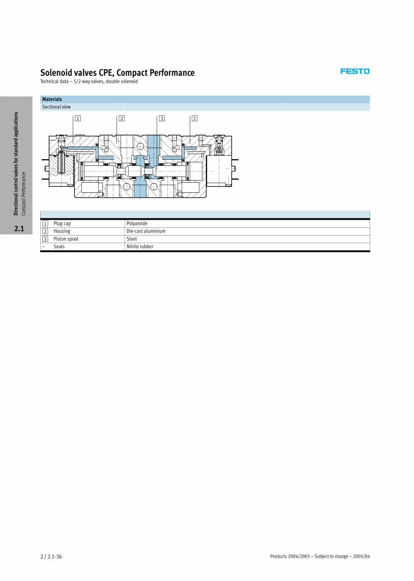
Solenoid valves CPE, Compact PerformanceTechnical data – 5/2−way valves, double solenoid
Materials
Sectional view
1 2 3 1
1 Plug cap Polyamide
2 Housing Die−cast aluminium
3 Piston spool Steel
– Seals Nitrile rubber
Dir
ecti
onal
con
trol
val
ves
for
stan
dard
app
lica
tion
s
Com
pact
Per
form
ance
2.1
2005/04 – Subject to change – Products 2004/2005 2 / 2.1−37
Solenoid valves CPE, Compact PerformanceTechnical data – 5/2−way valves, double solenoid
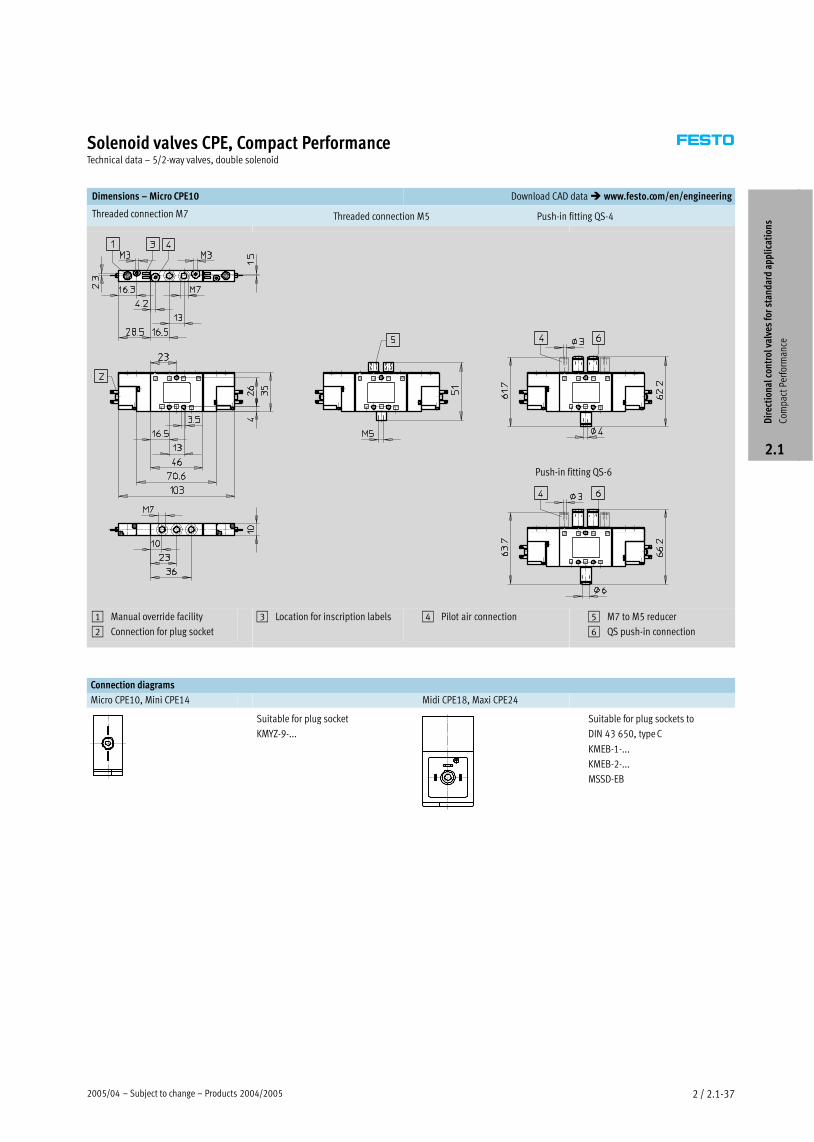
Dimensions – Micro CPE10 Download CAD data � www.festo.com/en/engineering
Threaded connection M7 Push−in fitting QS−4Threaded connection M5
Push−in fitting QS−6
1 Manual override facility
2 Connection for plug socket
3 Location for inscription labels 4 Pilot air connection 5 M7 to M5 reducer
6 QS push−in connection
Connection diagrams
Micro CPE10, Mini CPE14 Midi CPE18, Maxi CPE24
Suitable for plug socket
KMYZ−9−...
Suitable for plug sockets to
DIN 43 650, type C
KMEB−1−...
KMEB−2−...
MSSD−EBD
irec
tion
al c
ontr
ol v
alve
s fo
r st
anda
rd a
ppli
cati
ons
Com
pact
Per
form
ance
2.1
Products 2004/2005 – Subject to change – 2005/042 / 2.1−38
Solenoid valves CPE, Compact PerformanceTechnical data – 5/2−way valves, double solenoid
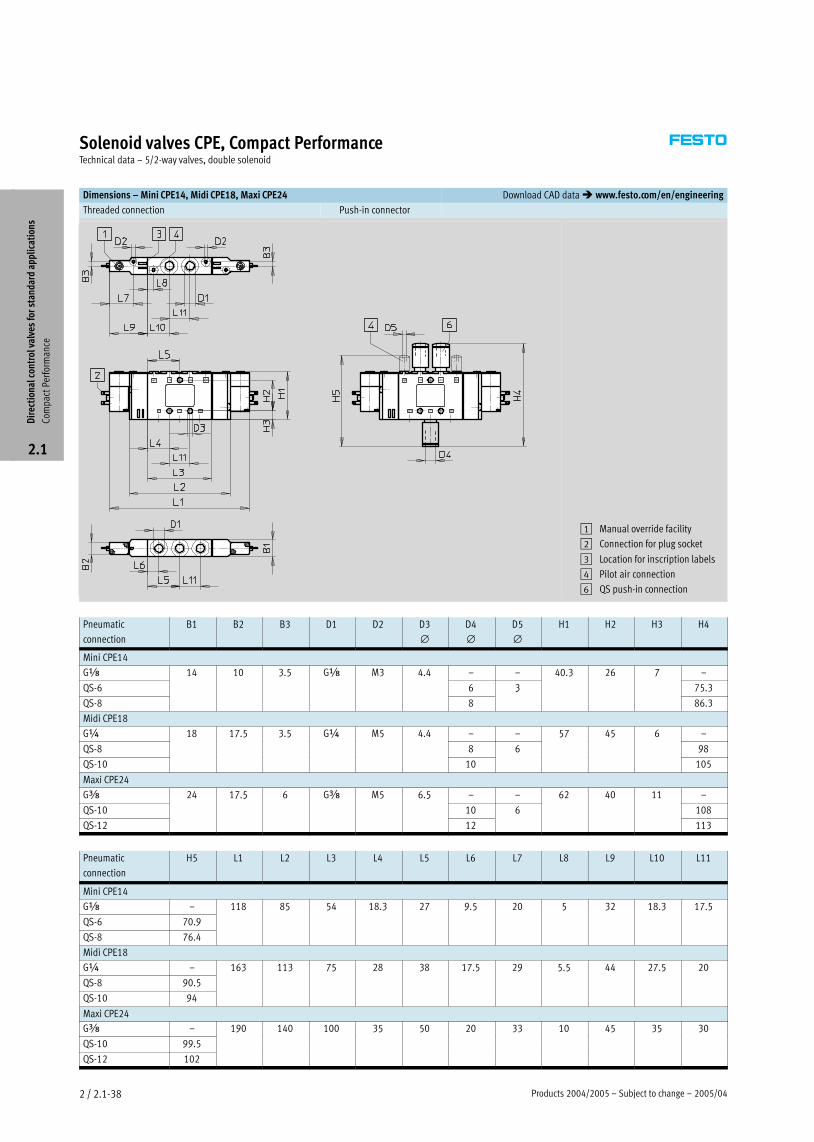
Dimensions – Mini CPE14, Midi CPE18, Maxi CPE24 Download CAD data � www.festo.com/en/engineering
Threaded connection Push−in connector
1 Manual override facility
2 Connection for plug socket
3 Location for inscription labels
4 Pilot air connection
6 QS push−in connection
Pneumatic
connection
B1 B2 B3 D1 D2 D3
∅D4
∅D5
∅H1 H2 H3 H4
Mini CPE14
Gx 14 10 3.5 Gx M3 4.4 – – 40.3 26 7 –
QS−6
3 5
6 3
3 7
75.3
QS−8 8
3
86.3
Midi CPE18
G¼ 18 17.5 3.5 G¼ M5 4.4 – – 57 45 6 –
QS−8
7 5 3 5
8 6
57 5
98
QS−10 10 105
Maxi CPE24
Gy 24 17.5 6 Gy M5 6.5 – – 62 40 11 –
QS−10
7 5 5
10 6 108
QS−12 12 113
Pneumatic
connection
H5 L1 L2 L3 L4 L5 L6 L7 L8 L9 L10 L11
Mini CPE14
Gx – 118 85 54 18.3 27 9.5 20 5 32 18.3 17.5
QS−6 70.9
5 5 3 7 9 5 5 3 3 7 5
QS−8 76.4
Midi CPE18
G¼ – 163 113 75 28 38 17.5 29 5.5 44 27.5 20
QS−8 90.5
3 3 75 3 7 5 9 5 5 7 5
QS−10 94
Maxi CPE24
Gy – 190 140 100 35 50 20 33 10 45 35 30
QS−10 99.5
9 35 5 33 5 35 3
QS−12 102
Dir
ecti
onal
con
trol
val
ves
for
stan
dard
app
lica
tion
s
Com
pact
Per
form
ance
2.1
2005/04 – Subject to change – Products 2004/2005 2 / 2.1−39
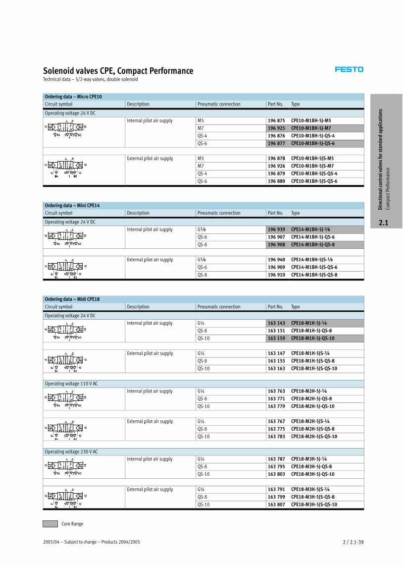
Solenoid valves CPE, Compact PerformanceTechnical data – 5/2−way valves, double solenoid
Ordering data – Micro CPE10
Circuit symbol Description Pneumatic connection Part No. Type
Operating voltage 24 V DC
Internal pilot air supply M5 196 875 CPE10−M1BH−5J−M5p pp y
M7 196 925 CPE10−M1BH−5J−M7
QS−4 196 876 CPE10−M1BH−5J−QS−4
QS−6 196 877 CPE10−M1BH−5J−QS−6
External pilot air supply M5 196 878 CPE10−M1BH−5JS−M5p pp y
M7 196 926 CPE10−M1BH−5JS−M7
QS−4 196 879 CPE10−M1BH−5JS−QS−4
QS−6 196 880 CPE10−M1BH−5JS−QS−6
Ordering data – Mini CPE14
Circuit symbol Description Pneumatic connection Part No. Type
Operating voltage 24 V DC
Internal pilot air supply Gx 196 939 CPE14−M1BH−5J−xp pp y
QS−6 196 907 CPE14−M1BH−5J−QS−6
QS−8 196 908 CPE14−M1BH−5J−QS−8
External pilot air supply Gx 196 940 CPE14−M1BH−5JS−xp pp y
QS−6 196 909 CPE14−M1BH−5JS−QS−6
QS−8 196 910 CPE14−M1BH−5JS−QS−8
Ordering data – Midi CPE18
Circuit symbol Description Pneumatic connection Part No. Type
Operating voltage 24 V DC
Internal pilot air supply G¼ 163 143 CPE18−M1H−5J−¼p pp y
QS−8 163 151 CPE18−M1H−5J−QS−8
QS−10 163 159 CPE18−M1H−5J−QS−10
External pilot air supply G¼ 163 147 CPE18−M1H−5JS−¼p pp y
QS−8 163 155 CPE18−M1H−5JS−QS−8
QS−10 163 163 CPE18−M1H−5JS−QS−10
Operating voltage 110 V AC
Internal pilot air supply G¼ 163 763 CPE18−M2H−5J−¼p pp y
QS−8 163 771 CPE18−M2H−5J−QS−8
QS−10 163 779 CPE18−M2H−5J−QS−10
External pilot air supply G¼ 163 767 CPE18−M2H−5JS−¼p pp y
QS−8 163 775 CPE18−M2H−5JS−QS−8
QS−10 163 783 CPE18−M2H−5JS−QS−10
Operating voltage 230 V AC
Internal pilot air supply G¼ 163 787 CPE18−M3H−5J−¼p pp y
QS−8 163 795 CPE18−M3H−5J−QS−8
QS−10 163 803 CPE18−M3H−5J−QS−10
External pilot air supply G¼ 163 791 CPE18−M3H−5JS−¼p pp y
QS−8 163 799 CPE18−M3H−5JS−QS−8
QS−10 163 807 CPE18−M3H−5JS−QS−10
Dir
ecti
onal
con
trol
val
ves
for
stan
dard
app
lica
tion
s
Com
pact
Per
form
ance
2.1
Core Range
Products 2004/2005 – Subject to change – 2005/042 / 2.1−40
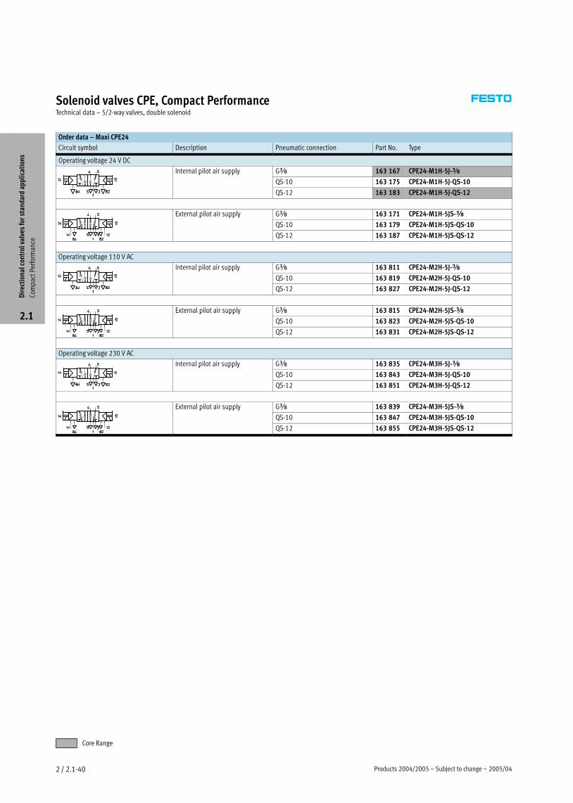
Solenoid valves CPE, Compact PerformanceTechnical data – 5/2−way valves, double solenoid
Order data – Maxi CPE24
Circuit symbol Description Pneumatic connection Part No. Type
Operating voltage 24 V DC
Internal pilot air supply Gy 163 167 CPE24−M1H−5J−yp pp y
QS−10 163 175 CPE24−M1H−5J−QS−10
QS−12 163 183 CPE24−M1H−5J−QS−12
External pilot air supply Gy 163 171 CPE24−M1H−5JS−yp pp y
QS−10 163 179 CPE24−M1H−5JS−QS−10
QS−12 163 187 CPE24−M1H−5JS−QS−12
Operating voltage 110 V AC
Internal pilot air supply Gy 163 811 CPE24−M2H−5J−yp pp y
QS−10 163 819 CPE24−M2H−5J−QS−10
QS−12 163 827 CPE24−M2H−5J−QS−12
External pilot air supply Gy 163 815 CPE24−M2H−5JS−yp pp y
QS−10 163 823 CPE24−M2H−5JS−QS−10
QS−12 163 831 CPE24−M2H−5JS−QS−12
Operating voltage 230 V AC
Internal pilot air supply Gy 163 835 CPE24−M3H−5J−yp pp y
QS−10 163 843 CPE24−M3H−5J−QS−10
QS−12 163 851 CPE24−M3H−5J−QS−12
External pilot air supply Gy 163 839 CPE24−M3H−5JS−yp pp y
QS−10 163 847 CPE24−M3H−5JS−QS−10
QS−12 163 855 CPE24−M3H−5JS−QS−12
Dir
ecti
onal
con
trol
val
ves
for
stan
dard
app
lica
tion
s
Com
pact
Per
form
ance
2.1
Core Range
2005/04 – Subject to change – Products 2004/2005 2 / 2.1−41
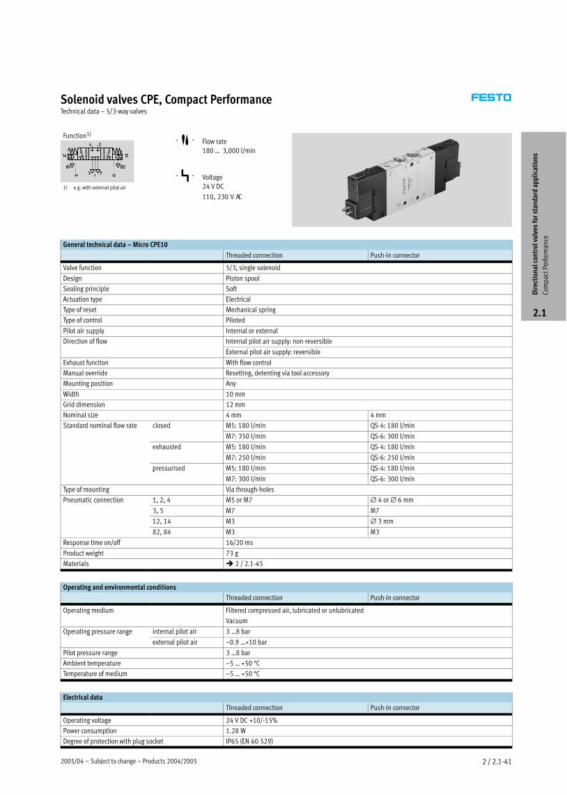
Solenoid valves CPE, Compact PerformanceTechnical data – 5/3−way valves
Function1)
1) e.g. with external pilot air
−M− Flow rate
180 Ī 3,000 l/min
−P− Voltage
24 V DC
110, 230 V AC
General technical data – Micro CPE10
Threaded connection Push−in connector
Valve function 5/3, single solenoid
Design Piston spool
Sealing principle Soft
Actuation type Electrical
Type of reset Mechanical spring
Type of control Piloted
Pilot air supply Internal or external
Direction of flow Internal pilot air supply: non−reversible
External pilot air supply: reversible
Exhaust function With flow control
Manual override Resetting, detenting via tool accessory
Mounting position Any
Width 10 mm
Grid dimension 12 mm
Nominal size 4 mm 4 mm
Standard nominal flow rate closed M5: 180 l/min QS−4: 180 l/min
M7: 350 l/min QS−6: 300 l/min
exhausted M5: 180 l/min QS−4: 180 l/min
M7: 250 l/min QS−6: 250 l/min
pressurised M5: 180 l/min QS−4: 180 l/minp
M7: 300 l/min QS−6: 300 l/min
Type of mounting Via through−holes
Pneumatic connection 1, 2, 4 M5 or M7 ∅ 4 or ∅ 6 mm
3, 5 M7 M7
12, 14 M3 ∅ 3 mm
82, 84 M3 M3
Response time on/off 16/20 ms
Product weight 73 g
Materials � 2 / 2.1−45
Operating and environmental conditions
Threaded connection Push−in connector
Operating medium Filtered compressed air, lubricated or unlubricated
Vacuum
Operating pressure range internal pilot air 3 Ī8 barp g p g
external pilot air –0.9 Ī+10 bar
Pilot pressure range 3 Ī8 bar
Ambient temperature –5 Ī +50 °C
Temperature of medium –5 Ī +50 °C
Electrical data
Threaded connection Push−in connector
Operating voltage 24 V DC +10/−15%
Power consumption 1.28 W
Degree of protection with plug socket IP65 (EN 60 529)
Dir
ecti
onal
con
trol
val
ves
for
stan
dard
app
lica
tion
s
Com
pact
Per
form
ance
2.1
Products 2004/2005 – Subject to change – 2005/042 / 2.1−42
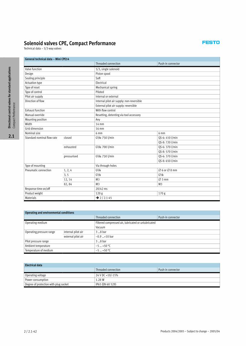
Solenoid valves CPE, Compact PerformanceTechnical data – 5/3−way valves
General technical data – Mini CPE14
Threaded connection Push−in connector
Valve function 5/3, single solenoid
Design Piston spool
Sealing principle Soft
Actuation type Electrical
Type of reset Mechanical spring
Type of control Piloted
Pilot air supply Internal or external
Direction of flow Internal pilot air supply: non−reversible
External pilot air supply: reversible
Exhaust function With flow control
Manual override Resetting, detenting via tool accessory
Mounting position Any
Width 14 mm
Grid dimension 16 mm
Nominal size 6 mm 6 mm
Standard nominal flow rate closed Gx: 750 l/min QS−6: 410 l/minx 75 /
QS−8: 720 l/min
exhausted Gx: 700 l/min QS−6: 370 l/minx 7 /
QS−8: 570 l/min
pressurised Gx: 750 l/min QS−6: 370 l/minp x 75 /
QS−8: 650 l/min
Type of mounting Via through−holes
Pneumatic connection 1, 2, 4 Gx ∅ 6 or ∅ 8 mm
3, 5 Gx Gx
12, 14 M3 ∅ 3 mm
82, 84 M3 M3
Response time on/off 20/42 ms
Product weight 120 g 170 g
Materials � 2 / 2.1−45
Operating and environmental conditions
Threaded connection Push−in connector
Operating medium Filtered compressed air, lubricated or unlubricated
Vacuum
Operating pressure range internal pilot air 3 Ī8 barp g p g
external pilot air –0.9 Ī+10 bar
Pilot pressure range 3 Ī8 bar
Ambient temperature –5 Ī +50 °C
Temperature of medium –5 Ī +50 °C
Electrical data
Threaded connection Push−in connector
Operating voltage 24 V DC +10/−15%
Power consumption 1.28 W
Degree of protection with plug socket IP65 (EN 60 529)
Dir
ecti
onal
con
trol
val
ves
for
stan
dard
app
lica
tion
s
Com
pact
Per
form
ance
2.1
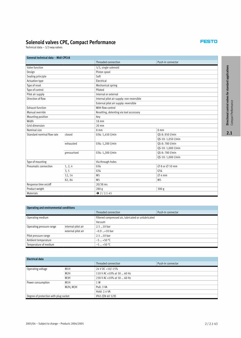
2005/04 – Subject to change – Products 2004/2005 2 / 2.1−43
Solenoid valves CPE, Compact PerformanceTechnical data – 5/3−way valves
General technical data – Midi CPE18
Threaded connection Push−in connector
Valve function 5/3, single solenoid
Design Piston spool
Sealing principle Soft
Actuation type Electrical
Type of reset Mechanical spring
Type of control Piloted
Pilot air supply Internal or external
Direction of flow Internal pilot air supply: non−reversible
External pilot air supply: reversible
Exhaust function With flow control
Manual override Resetting, detenting via tool accessory
Mounting position Any
Width 18 mm
Grid dimension 20 mm
Nominal size 8 mm 8 mm
Standard nominal flow rate closed G¼: 1,450 l/min QS−8: 850 l/min¼ , 5 /
QS−10: 1,050 l/min
exhausted G¼: 1,200 l/min QS−8: 780 l/min¼ , /
QS−10: 1,000 l/min
pressurised G¼: 1,300 l/min QS−8: 780 l/minp ¼ ,3 /
QS−10: 1,000 l/min
Type of mounting Via through−holes
Pneumatic connection 1, 2, 4 G¼ ∅ 8 or ∅ 10 mm
3, 5 G¼ G¼
12, 14 M5 ∅ 4 mm
82, 84 M5 M5
Response time on/off 20/38 ms
Product weight 280 g 300 g
Materials � 2 / 2.1−45
Operating and environmental conditions
Threaded connection Push−in connector
Operating medium Filtered compressed air, lubricated or unlubricated
Vacuum
Operating pressure range internal pilot air 2.5 Ī10 barp g p g
external pilot air –0.9 Ī+10 bar
Pilot pressure range 2.5 Ī10 bar
Ambient temperature –5 Ī +50 °C
Temperature of medium –5 Ī +50 °C
Electrical data
Threaded connection Push−in connector
Operating voltage M1H 24 V DC +10/−15%p g g
M2H 110 V AC ±10% at 50 Ī 60 Hz
M3H 230 V AC ±10% at 50 Ī 60 Hz
Power consumption M1H 1 Wp
M2H, M3H Pull: 3 VA, 3
Hold: 2.4 VA
Degree of protection with plug socket IP65 (EN 60 529)
Dir
ecti
onal
con
trol
val
ves
for
stan
dard
app
lica
tion
s
Com
pact
Per
form
ance
2.1
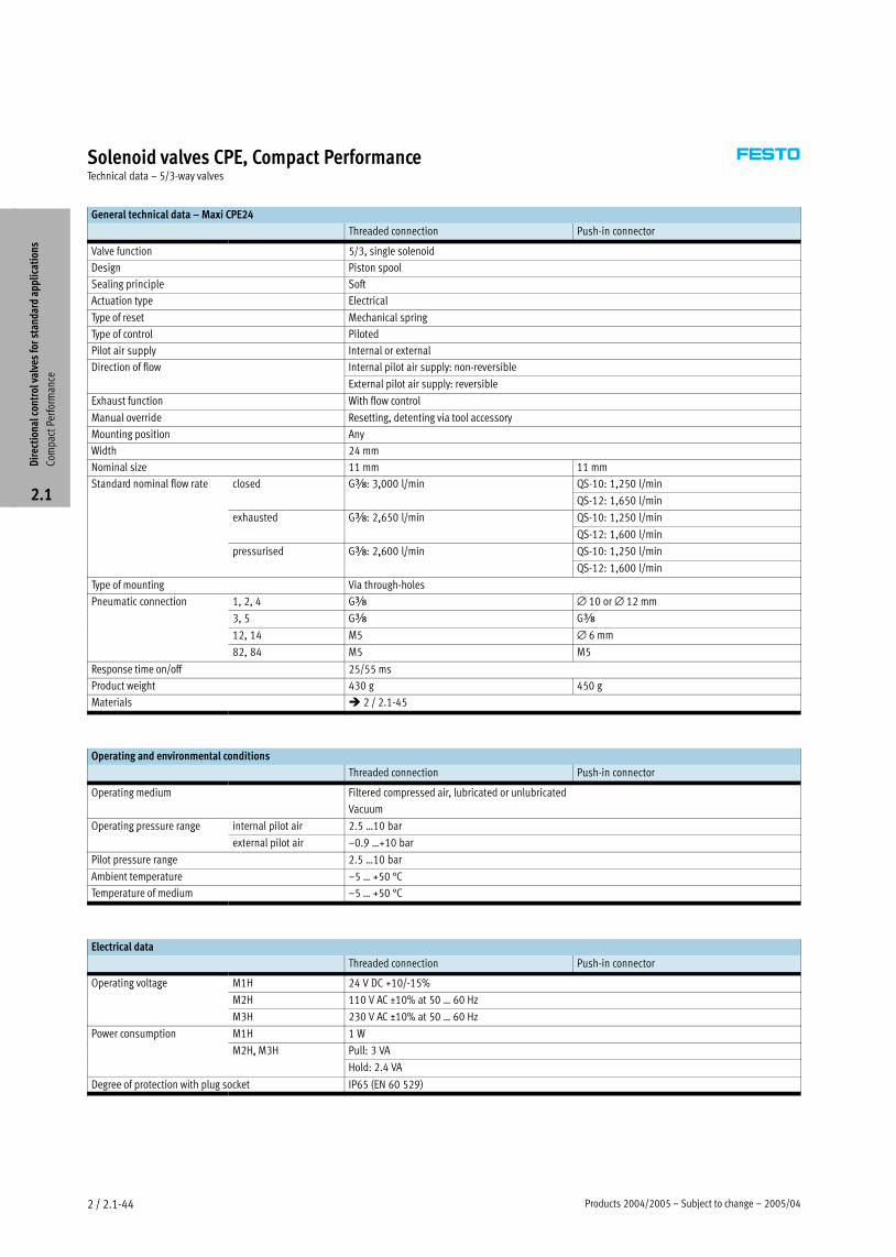
Products 2004/2005 – Subject to change – 2005/042 / 2.1−44
Solenoid valves CPE, Compact PerformanceTechnical data – 5/3−way valves
General technical data – Maxi CPE24
Threaded connection Push−in connector
Valve function 5/3, single solenoid
Design Piston spool
Sealing principle Soft
Actuation type Electrical
Type of reset Mechanical spring
Type of control Piloted
Pilot air supply Internal or external
Direction of flow Internal pilot air supply: non−reversible
External pilot air supply: reversible
Exhaust function With flow control
Manual override Resetting, detenting via tool accessory
Mounting position Any
Width 24 mm
Nominal size 11 mm 11 mm
Standard nominal flow rate closed Gy: 3,000 l/min QS−10: 1,250 l/miny 3, /
QS−12: 1,650 l/min
exhausted Gy: 2,650 l/min QS−10: 1,250 l/miny , 5 /
QS−12: 1,600 l/min
pressurised Gy: 2,600 l/min QS−10: 1,250 l/minp y , /
QS−12: 1,600 l/min
Type of mounting Via through−holes
Pneumatic connection 1, 2, 4 Gy ∅ 10 or ∅ 12 mm
3, 5 Gy Gy
12, 14 M5 ∅ 6 mm
82, 84 M5 M5
Response time on/off 25/55 ms
Product weight 430 g 450 g
Materials � 2 / 2.1−45
Operating and environmental conditions
Threaded connection Push−in connector
Operating medium Filtered compressed air, lubricated or unlubricated
Vacuum
Operating pressure range internal pilot air 2.5 Ī10 barp g p g
external pilot air –0.9 Ī+10 bar
Pilot pressure range 2.5 Ī10 bar
Ambient temperature –5 Ī +50 °C
Temperature of medium –5 Ī +50 °C
Electrical data
Threaded connection Push−in connector
Operating voltage M1H 24 V DC +10/−15%p g g
M2H 110 V AC ±10% at 50 Ī 60 Hz
M3H 230 V AC ±10% at 50 Ī 60 Hz
Power consumption M1H 1 Wp
M2H, M3H Pull: 3 VA, 3
Hold: 2.4 VA
Degree of protection with plug socket IP65 (EN 60 529)
Dir
ecti
onal
con
trol
val
ves
for
stan
dard
app
lica
tion
s
Com
pact
Per
form
ance
2.1
2005/04 – Subject to change – Products 2004/2005 2 / 2.1−45
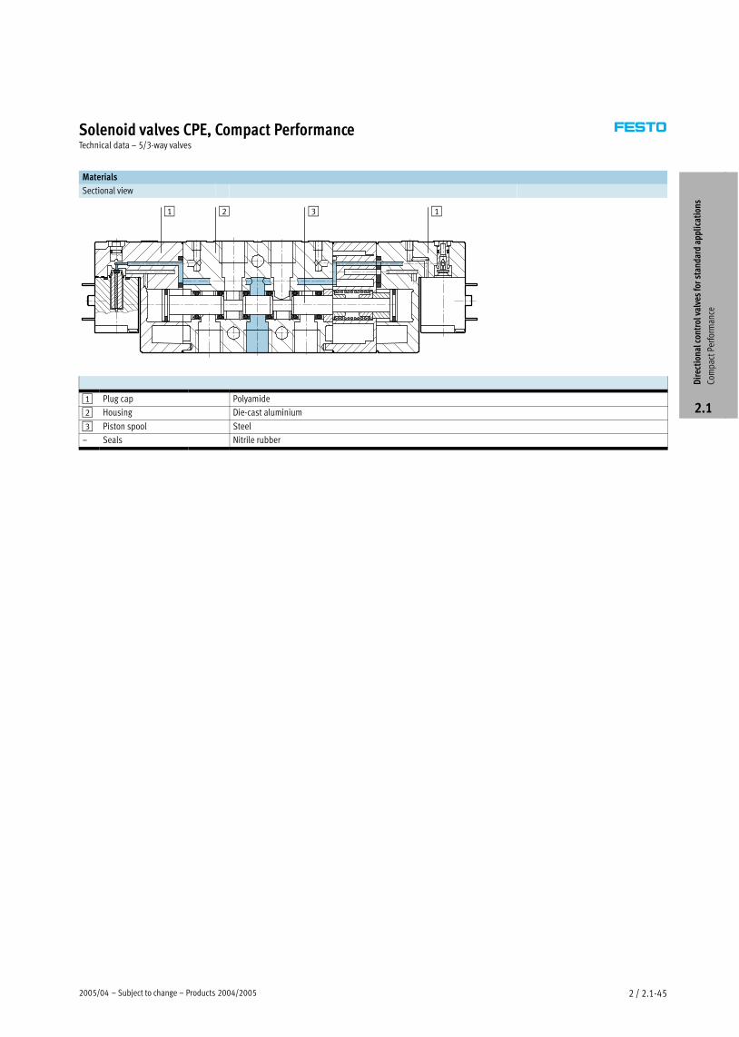
Solenoid valves CPE, Compact PerformanceTechnical data – 5/3−way valves
Materials
Sectional view
1 2 3 1
1 Plug cap Polyamide
2 Housing Die−cast aluminium
3 Piston spool Steel
– Seals Nitrile rubber
Dir
ecti
onal
con
trol
val
ves
for
stan
dard
app
lica
tion
s
Com
pact
Per
form
ance
2.1
Products 2004/2005 – Subject to change – 2005/042 / 2.1−46
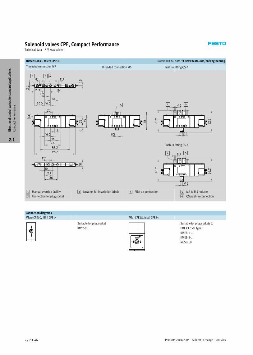
Solenoid valves CPE, Compact PerformanceTechnical data – 5/3−way valves
Dimensions – Micro CPE10 Download CAD data � www.festo.com/en/engineering
Threaded connection M7 Push−in fitting QS−4Threaded connection M5
Push−in fitting QS−6
1 Manual override facility
2 Connection for plug socket
3 Location for inscription labels 4 Pilot air connection 5 M7 to M5 reducer
6 QS push−in connection
Connection diagrams
Micro CPE10, Mini CPE14 Midi CPE18, Maxi CPE24
Suitable for plug socket
KMYZ−9−...
Suitable for plug sockets to
DIN 43 650, type C
KMEB−1−...
KMEB−2−...
MSSD−EB
Dir
ecti
onal
con
trol
val
ves
for
stan
dard
app
lica
tion
s
Com
pact
Per
form
ance
2.1
2005/04 – Subject to change – Products 2004/2005 2 / 2.1−47
Solenoid valves CPE, Compact PerformanceTechnical data – 5/3−way valves
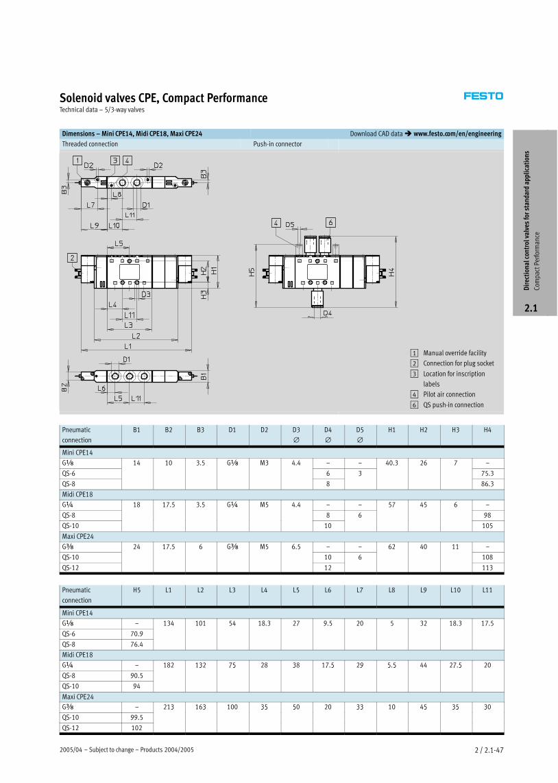
Dimensions – Mini CPE14, Midi CPE18, Maxi CPE24 Download CAD data � www.festo.com/en/engineering
Threaded connection Push−in connector
1 Manual override facility
2 Connection for plug socket
3 Location for inscription
labels
4 Pilot air connection
6 QS push−in connection
Pneumatic
connection
B1 B2 B3 D1 D2 D3
∅D4
∅D5
∅H1 H2 H3 H4
Mini CPE14
Gx 14 10 3.5 Gx M3 4.4 – – 40.3 26 7 –
QS−6
3 5
6 3
3 7
75.3
QS−8 8
3
86.3
Midi CPE18
G¼ 18 17.5 3.5 G¼ M5 4.4 – – 57 45 6 –
QS−8
7 5 3 5
8 6
57 5
98
QS−10 10 105
Maxi CPE24
Gy 24 17.5 6 Gy M5 6.5 – – 62 40 11 –
QS−10
7 5 5
10 6 108
QS−12 12 113
Pneumatic
connection
H5 L1 L2 L3 L4 L5 L6 L7 L8 L9 L10 L11
Mini CPE14
Gx – 134 101 54 18.3 27 9.5 20 5 32 18.3 17.5
QS−6 70.9
3 5 3 7 9 5 5 3 3 7 5
QS−8 76.4
Midi CPE18
G¼ – 182 132 75 28 38 17.5 29 5.5 44 27.5 20
QS−8 90.5
3 75 3 7 5 9 5 5 7 5
QS−10 94
Maxi CPE24
Gy – 213 163 100 35 50 20 33 10 45 35 30
QS−10 99.5
3 3 35 5 33 5 35 3
QS−12 102
Dir
ecti
onal
con
trol
val
ves
for
stan
dard
app
lica
tion
s
Com
pact
Per
form
ance
2.1
Products 2004/2005 – Subject to change – 2005/042 / 2.1−48
Solenoid valves CPE, Compact PerformanceTechnical data – 5/3−way valves
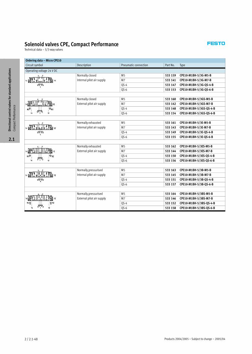
Ordering data – Micro CPE10
Circuit symbol Description Pneumatic connection Part No. Type
Operating voltage 24 V DC
Normally closed M5 533 159 CPE10−M1BH−5/3G−M5−By
Internal pilot air supply M7 533 141 CPE10−M1BH−5/3G−M7−Bp pp y
QS−4 533 147 CPE10−M1BH−5/3G−QS−4−B
QS−6 533 153 CPE10−M1BH−5/3G−QS−6−B
Normally closed M5 533 160 CPE10−M1BH−5/3GS−M5−By
External pilot air supply M7 533 142 CPE10−M1BH−5/3GS−M7−Bp pp y
QS−4 533 148 CPE10−M1BH−5/3GS−QS−4−B
QS−6 533 154 CPE10−M1BH−5/3GS−QS−6−B
Normally exhausted M5 533 161 CPE10−M1BH−5/3E−M5−By
Internal pilot air supply M7 533 143 CPE10−M1BH−5/3E−M7−Bp pp y
QS−4 533 149 CPE10−M1BH−5/3E−QS−4−B
QS−6 533 155 CPE10−M1BH−5/3E−QS−6−B
Normally exhausted M5 533 162 CPE10−M1BH−5/3ES−M5−By
External pilot air supply M7 533 144 CPE10−M1BH−5/3ES−M7−Bp pp y
QS−4 533 150 CPE10−M1BH−5/3ES−QS−4−B
QS−6 533 156 CPE10−M1BH−5/3ES−QS−6−B
Normally pressurised M5 533 163 CPE10−M1BH−5/3B−M5−By p
Internal pilot air supply M7 533 145 CPE10−M1BH−5/3B−M7−Bp pp y
QS−4 533 151 CPE10−M1BH−5/3B−QS−4−B
QS−6 533 157 CPE10−M1BH−5/3B−QS−6−B
Normally pressurised M5 533 164 CPE10−M1BH−5/3BS−M5−By p
External pilot air supply M7 533 146 CPE10−M1BH−5/3BS−M7−Bp pp y
QS−4 533 152 CPE10−M1BH−5/3BS−QS−4−B
QS−6 533 158 CPE10−M1BH−5/3BS−QS−6−B
Dir
ecti
onal
con
trol
val
ves
for
stan
dard
app
lica
tion
s
Com
pact
Per
form
ance
2.1
2005/04 – Subject to change – Products 2004/2005 2 / 2.1−49
Solenoid valves CPE, Compact PerformanceTechnical data – 5/3−way valves
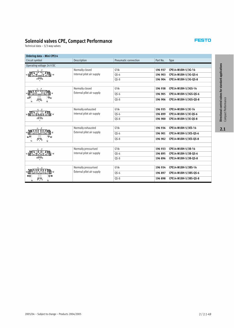
Ordering data – Mini CPE14
Circuit symbol Description Pneumatic connection Part No. Type
Operating voltage 24 V DC
Normally closed Gx 196 937 CPE14−M1BH−5/3G−xy
Internal pilot air supply QS−6 196 903 CPE14−M1BH−5/3G−QS−6
QS−8 196 904 CPE14−M1BH−5/3G−QS−8
Normally closed
E t l il t i l
Gx 196 938 CPE14−M1BH−5/3GS−x
External pilot air supply QS−6 196 905 CPE14−M1BH−5/3GS−QS−6
QS−8 196 906 CPE14−M1BH−5/3GS−QS−8
Normally exhausted Gx 196 935 CPE14−M1BH−5/3E−xy
Internal pilot air supply QS−6 196 899 CPE14−M1BH−5/3E−QS−6
QS−8 196 900 CPE14−M1BH−5/3E−QS−8
Normally exhausted
E t l il t i l
Gx 196 936 CPE14−M1BH−5/3ES−x
External pilot air supply QS−6 196 901 CPE14−M1BH−5/3ES−QS−6
QS−8 196 902 CPE14−M1BH−5/3ES−QS−8
Normally pressurised Gx 196 933 CPE14−M1BH−5/3B−xy p
Internal pilot air supply QS−6 196 895 CPE14−M1BH−5/3B−QS−6
QS−8 196 896 CPE14−M1BH−5/3B−QS−8
Normally pressurised
E t l il t i l
Gx 196 934 CPE14−M1BH−5/3BS−x
External pilot air supply QS−6 196 897 CPE14−M1BH−5/3BS−QS−6
QS−8 196 898 CPE14−M1BH−5/3BS−QS−8
Dir
ecti
onal
con
trol
val
ves
for
stan
dard
app
lica
tion
s
Com
pact
Per
form
ance
2.1

Products 2004/2005 – Subject to change – 2005/042 / 2.1−50
Solenoid valves CPE, Compact PerformanceTechnical data – 5/3−way valves
Ordering data – Midi CPE18
Circuit symbol Description Pneumatic connection Part No. Type
Operating voltage 24 V DC
Normally closed G¼ 170 247 CPE18−M1H−5/3G−¼y
Internal pilot air supply QS−8 170 253 CPE18−M1H−5/3G−QS−8
QS−10 170 259 CPE18−M1H−5/3G−QS−10
Normally closed
E t l il t i l
G¼ 170 248 CPE18−M1H−5/3GS−¼
External pilot air supply QS−8 170 254 CPE18−M1H−5/3GS−QS−8
QS−10 170 260 CPE18−M1H−5/3GS−QS−10
Normally exhausted G¼ 170 249 CPE18−M1H−5/3E−¼y
Internal pilot air supply QS−8 170 255 CPE18−M1H−5/3E−QS−8
QS−10 170 261 CPE18−M1H−5/3E−QS−10
Normally exhausted
E t l il t i l
G¼ 170 250 CPE18−M1H−5/3ES−¼
External pilot air supply QS−8 170 256 CPE18−M1H−5/3ES−QS−8
QS−10 170 262 CPE18−M1H−5/3ES−QS−10
Normally pressurised G¼ 170 251 CPE18−M1H−5/3B−¼y p
Internal pilot air supply QS−8 170 257 CPE18−M1H−5/3B−QS8
QS−10 170 263 CPE18−M1H−5/3B−QS10
Normally pressurised
E t l il t i l
G¼ 170 252 CPE18−M1H−5/3BS−¼
External pilot air supply QS−8 170 258 CPE18−M1H−5/3BS−QS−8
QS−10 170 264 CPE18−M1H−5/3BS−QS−10
Operating voltage 110 V AC
Normally closed G¼ 170 283 CPE18−M2H−5/3G−¼y
Internal pilot air supply QS−8 170 289 CPE18−M2H−5/3G−QS−8
QS−10 170 295 CPE18−M2H−5/3G−QS−10
Normally closed
E t l il t i l
G¼ 170 284 CPE18−M2H−5/3GS−¼
External pilot air supply QS−8 170 290 CPE18−M2H−5/3GS−QS−8
QS−10 170 296 CPE18−M2H−5/3GS−QS10
Normally exhausted G¼ 170 285 CPE18−M2H−5/3E−¼y
Internal pilot air supply QS−8 170 291 CPE18−M2H−5/3E−QS−8
QS−10 170 297 CPE18−M2H−5/3E−QS−10
Normally exhausted
E t l il t i l
G¼ 170 286 CPE18−M2H−5/3ES−¼
External pilot air supply QS−8 170 292 CPE18−M2H−5/3ES−QS−8
QS−10 170 298 CPE18−M2H−5/3ES−QS10
Normally pressurised G¼ 170 287 CPE18−M2H−5/3B−¼y p
Internal pilot air supply QS−8 170 293 CPE18−M2H−5/3B−QS−8
QS−10 170 299 CPE18−M2H−5/3B−QS−10
Normally pressurised
E t l il t i l
G¼ 170 288 CPE18−M2H−5/3BS−¼
External pilot air supply QS−8 170 294 CPE18−M2H−5/3BS−QS−8
QS−10 170 300 CPE18−M2H−5/3BS−QS−10
Dir
ecti
onal
con
trol
val
ves
for
stan
dard
app
lica
tion
s
Com
pact
Per
form
ance
2.1

2005/04 – Subject to change – Products 2004/2005 2 / 2.1−51
Solenoid valves CPE, Compact PerformanceTechnical data – 5/3−way valves
Ordering data – Midi CPE18
Circuit symbol Description Pneumatic connection Part No. Type
Operating voltage 230 V AC
Normally closed G¼ 170 319 CPE18−M3H−5/3G−¼y
Internal pilot air supply QS−8 170 325 CPE18−M3H−5/3G−QS−8
QS−10 170 331 CPE18−M3H−5/3G−QS−10
Normally closed
E t l il t i l
G¼ 170 320 CPE18−M3H−5/3GS−¼
External pilot air supply QS−8 170 326 CPE18−M3H−5/3GS−QS−8
QS−10 170 332 CPE18−M3H−5/3GS−QS10
Normally exhausted G¼ 170 321 CPE18−M3H−5/3E−¼y
Internal pilot air supply QS−8 170 327 CPE18−M3H−5/3E−QS−8
QS−10 170 333 CPE18−M3H−5/3E−QS−10
Normally exhausted
E t l il t i l
G¼ 170 322 CPE18−M3H−5/3ES−¼
External pilot air supply QS−8 170 328 CPE18−M3H−5/3ES−QS−8
QS−10 170 334 CPE18−M3H−5/3ES−QS10
Normally pressurised G¼ 170 323 CPE18−M3H−5/3B−¼y p
Internal pilot air supply QS−8 170 329 CPE18−M3H−5/3B−QS−8
QS−10 170 335 CPE18−M3H−5/3B−QS−10
Normally pressurised
E t l il t i l
G¼ 170 324 CPE18−M3H−5/3BS−¼
External pilot air supply QS−8 170 330 CPE18−M3H−5/3BS−QS−8
QS−10 170 336 CPE18−M3H−5/3BS−QS−10
Dir
ecti
onal
con
trol
val
ves
for
stan
dard
app
lica
tion
s
Com
pact
Per
form
ance
2.1
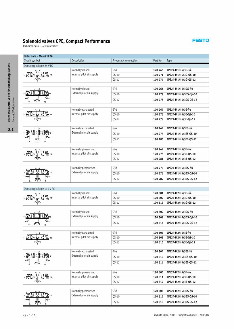
Products 2004/2005 – Subject to change – 2005/042 / 2.1−52
Solenoid valves CPE, Compact PerformanceTechnical data – 5/3−way valves
Order data – Maxi CPE24
Circuit symbol Description Pneumatic connection Part No. Type
Operating voltage 24 V DC
Normally closed Gy 170 265 CPE24−M1H−5/3G−yy
Internal pilot air supply QS−10 170 271 CPE24−M1H−5/3G−QS−10
QS−12 170 277 CPE24−M1H−5/3G−QS−12
Normally closed
E t l il t i l
Gy 170 266 CPE24−M1H−5/3GS−y
External pilot air supply QS−10 170 272 CPE24−M1H−5/3GS−QS−10
QS−12 170 278 CPE24−M1H−5/3GS−QS−12
Normally exhausted Gy 170 267 CPE24−M1H−5/3E−yy
Internal pilot air supply QS−10 170 273 CPE24−M1H−5/3E−QS−10
QS−12 170 279 CPE24−M1H−5/3E−QS−12
Normally exhausted
E t l il t i l
Gy 170 268 CPE24−M1H−5/3ES−y
External pilot air supply QS−10 170 274 CPE24−M1H−5/3ES−QS−10
QS−12 170 280 CPE24−M1H−5/3ES−QS−12
Normally pressurised Gy 170 269 CPE24−M1H−5/3B−yy p
Internal pilot air supply QS−10 170 275 CPE24−M1H−5/3B−QS−10
QS−12 170 281 CPE24−M1H−5/3B−QS−12
Normally pressurised
E t l il t i l
Gy 170 270 CPE24−M1H−5/3BS−y
External pilot air supply QS−10 170 276 CPE24−M1H−5/3BS−QS−10
QS−12 170 282 CPE24−M1H−5/3BS−QS−12
Operating voltage 110 V AC
Normally closed Gy 170 301 CPE24−M2H−5/3G−yy
Internal pilot air supply QS−10 170 307 CPE24−M2H−5/3G−QS−10
QS−12 170 313 CPE24−M2H−5/3G−QS−12
Normally closed
E t l il t i l
Gy 170 302 CPE24−M2H−5/3GS−y
External pilot air supply QS−10 170 308 CPE24−M2H−5/3GS−QS−10
QS−12 170 314 CPE24−M2H−5/3GS−QS−12
Normally exhausted Gy 170 303 CPE24−M2H−5/3E−yy
Internal pilot air supply QS−10 170 309 CPE24−M2H−5/3E−QS−10
QS−12 170 315 CPE24−M2H−5/3E−QS−12
Normally exhausted
E t l il t i l
Gy 170 304 CPE24−M2H−5/3ES−y
External pilot air supply QS−10 170 310 CPE24−M2H−5/3ES−QS−10
QS−12 170 316 CPE24−M2H−5/3ES−QS−12
Normally pressurised Gy 170 305 CPE24−M2H−5/3B−yy p
Internal pilot air supply QS−10 170 311 CPE24−M2H−5/3B−QS−10
QS−12 170 317 CPE24−M2H−5/3B−QS−12
Normally pressurised
E t l il t i l
Gy 170 306 CPE24−M2H−5/3BS−y
External pilot air supply QS−10 170 312 CPE24−M2H−5/3BS−QS−10
QS−12 170 318 CPE24−M2H−5/3BS−QS−12
Dir
ecti
onal
con
trol
val
ves
for
stan
dard
app
lica
tion
s
Com
pact
Per
form
ance
2.1
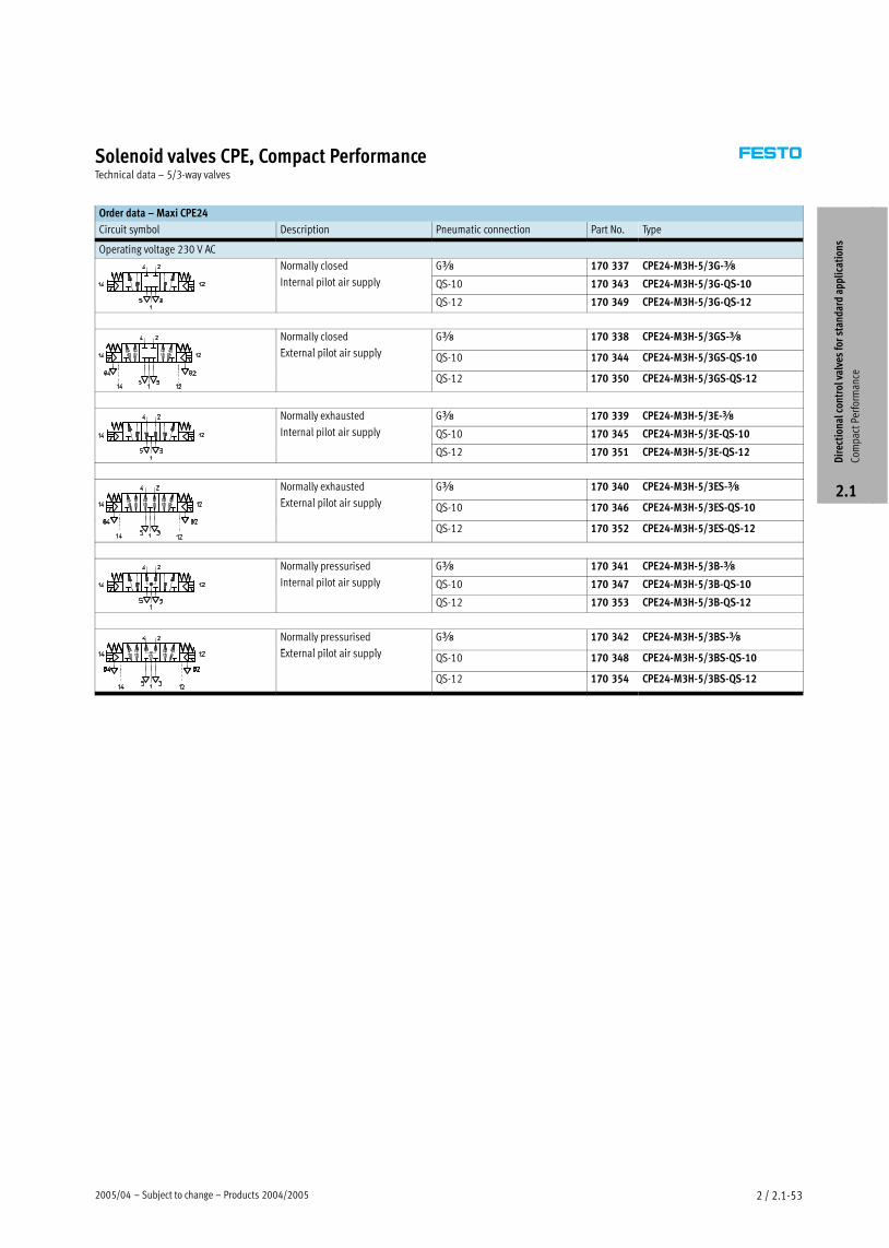
2005/04 – Subject to change – Products 2004/2005 2 / 2.1−53
Solenoid valves CPE, Compact PerformanceTechnical data – 5/3−way valves
Order data – Maxi CPE24
Circuit symbol Description Pneumatic connection Part No. Type
Operating voltage 230 V AC
Normally closed Gy 170 337 CPE24−M3H−5/3G−yy
Internal pilot air supply QS−10 170 343 CPE24−M3H−5/3G−QS−10
QS−12 170 349 CPE24−M3H−5/3G−QS−12
Normally closed
E t l il t i l
Gy 170 338 CPE24−M3H−5/3GS−y
External pilot air supply QS−10 170 344 CPE24−M3H−5/3GS−QS−10
QS−12 170 350 CPE24−M3H−5/3GS−QS−12
Normally exhausted Gy 170 339 CPE24−M3H−5/3E−yy
Internal pilot air supply QS−10 170 345 CPE24−M3H−5/3E−QS−10
QS−12 170 351 CPE24−M3H−5/3E−QS−12
Normally exhausted
E t l il t i l
Gy 170 340 CPE24−M3H−5/3ES−y
External pilot air supply QS−10 170 346 CPE24−M3H−5/3ES−QS−10
QS−12 170 352 CPE24−M3H−5/3ES−QS−12
Normally pressurised Gy 170 341 CPE24−M3H−5/3B−yy p
Internal pilot air supply QS−10 170 347 CPE24−M3H−5/3B−QS−10
QS−12 170 353 CPE24−M3H−5/3B−QS−12
Normally pressurised
E t l il t i l
Gy 170 342 CPE24−M3H−5/3BS−y
External pilot air supply QS−10 170 348 CPE24−M3H−5/3BS−QS−10
QS−12 170 354 CPE24−M3H−5/3BS−QS−12
Dir
ecti
onal
con
trol
val
ves
for
stan
dard
app
lica
tion
s
Com
pact
Per
form
ance
2.1
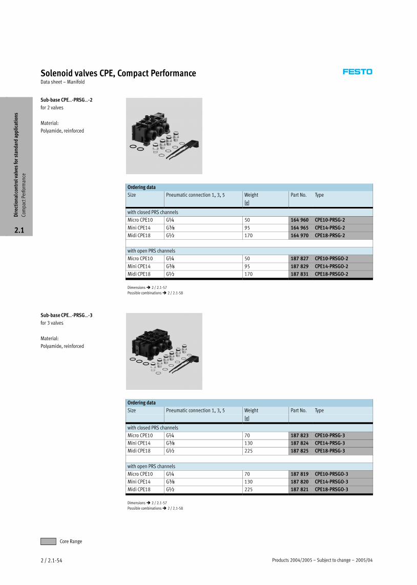
Products 2004/2005 – Subject to change – 2005/042 / 2.1−54
Solenoid valves CPE, Compact PerformanceData sheet – Manifold
Sub−base CPEĪ−PRSGĪ−2
for 2 valves
Material:
Polyamide, reinforced
Ordering data
Size Pneumatic connection 1, 3, 5 Weight Part No. Type, 3, 5
[g]
with closed PRS channels
Micro CPE10 G¼ 50 164 960 CPE10−PRSG−2
Mini CPE14 Gy 95 164 965 CPE14−PRSG−2
Midi CPE18 G½ 170 164 970 CPE18−PRSG−2
with open PRS channels
Micro CPE10 G¼ 50 187 827 CPE10−PRSGO−2
Mini CPE14 Gy 95 187 829 CPE14−PRSGO−2
Midi CPE18 G½ 170 187 831 CPE18−PRSGO−2
Dimensions � 2 / 2.1−57
Possible combinations � 2 / 2.1−58
Sub−base CPEĪ−PRSGĪ−3
for 3 valves
Material:
Polyamide, reinforced
Ordering data
Size Pneumatic connection 1, 3, 5 Weight Part No. Type, 3, 5
[g]
with closed PRS channels
Micro CPE10 G¼ 70 187 823 CPE10−PRSG−3
Mini CPE14 Gy 130 187 824 CPE14−PRSG−3
Midi CPE18 G½ 225 187 825 CPE18−PRSG−3
with open PRS channels
Micro CPE10 G¼ 70 187 819 CPE10−PRSGO−3
Mini CPE14 Gy 130 187 820 CPE14−PRSGO−3
Midi CPE18 G½ 225 187 821 CPE18−PRSGO−3
Dimensions � 2 / 2.1−57
Possible combinations � 2 / 2.1−58
Dir
ecti
onal
con
trol
val
ves
for
stan
dard
app
lica
tion
s
Com
pact
Per
form
ance
2.1
Core Range
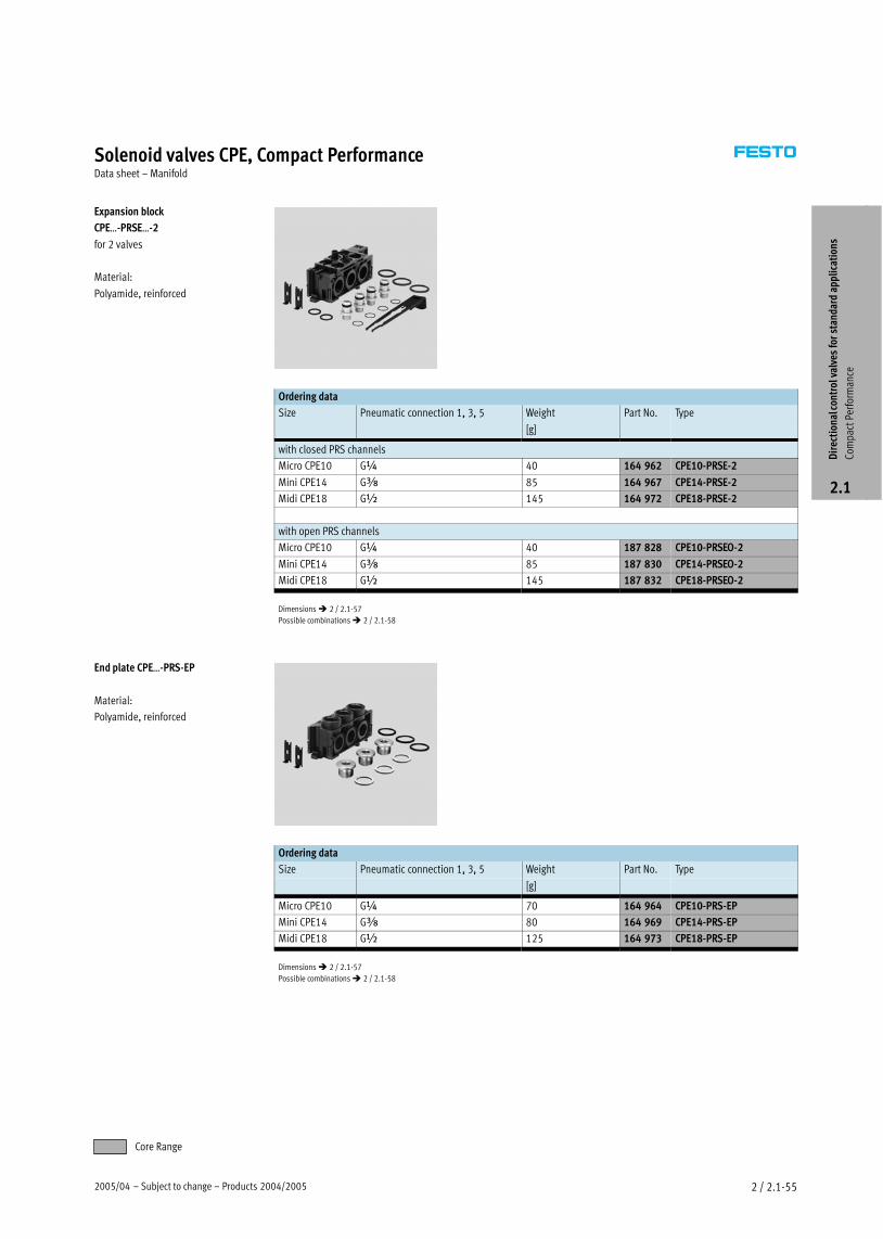
2005/04 – Subject to change – Products 2004/2005 2 / 2.1−55
Solenoid valves CPE, Compact PerformanceData sheet – Manifold
Expansion block
CPEĪ−PRSEĪ−2
for 2 valves
Material:
Polyamide, reinforced
Ordering data
Size Pneumatic connection 1, 3, 5 Weight Part No. Type, 3, 5
[g]
with closed PRS channels
Micro CPE10 G¼ 40 164 962 CPE10−PRSE−2
Mini CPE14 Gy 85 164 967 CPE14−PRSE−2
Midi CPE18 G½ 145 164 972 CPE18−PRSE−2
with open PRS channels
Micro CPE10 G¼ 40 187 828 CPE10−PRSEO−2
Mini CPE14 Gy 85 187 830 CPE14−PRSEO−2
Midi CPE18 G½ 145 187 832 CPE18−PRSEO−2
Dimensions � 2 / 2.1−57
Possible combinations � 2 / 2.1−58
End plate CPEĪ−PRS−EP
Material:
Polyamide, reinforced
Ordering data
Size Pneumatic connection 1, 3, 5 Weight Part No. Type, 3, 5
[g]
Micro CPE10 G¼ 70 164 964 CPE10−PRS−EP
Mini CPE14 Gy 80 164 969 CPE14−PRS−EP
Midi CPE18 G½ 125 164 973 CPE18−PRS−EP
Dimensions � 2 / 2.1−57
Possible combinations � 2 / 2.1−58
Dir
ecti
onal
con
trol
val
ves
for
stan
dard
app
lica
tion
s
Com
pact
Per
form
ance
2.1
Core Range
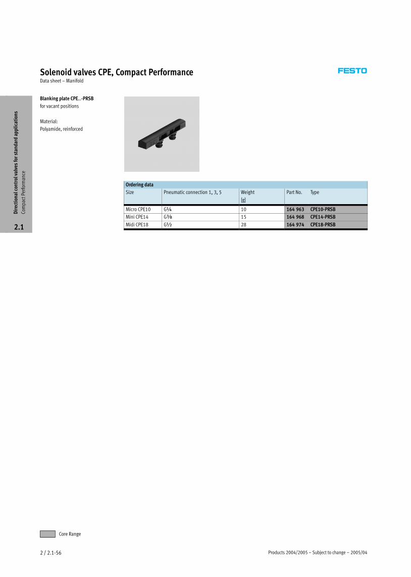
Products 2004/2005 – Subject to change – 2005/042 / 2.1−56
Solenoid valves CPE, Compact PerformanceData sheet – Manifold
Blanking plate CPEĪ−PRSB
for vacant positions
Material:
Polyamide, reinforced
Ordering data
Size Pneumatic connection 1, 3, 5 Weight Part No. Type, 3, 5
[g]
Micro CPE10 G¼ 10 164 963 CPE10−PRSB
Mini CPE14 Gy 15 164 968 CPE14−PRSB
Midi CPE18 G½ 28 164 974 CPE18−PRSB
Dir
ecti
onal
con
trol
val
ves
for
stan
dard
app
lica
tion
s
Com
pact
Per
form
ance
2.1
Core Range
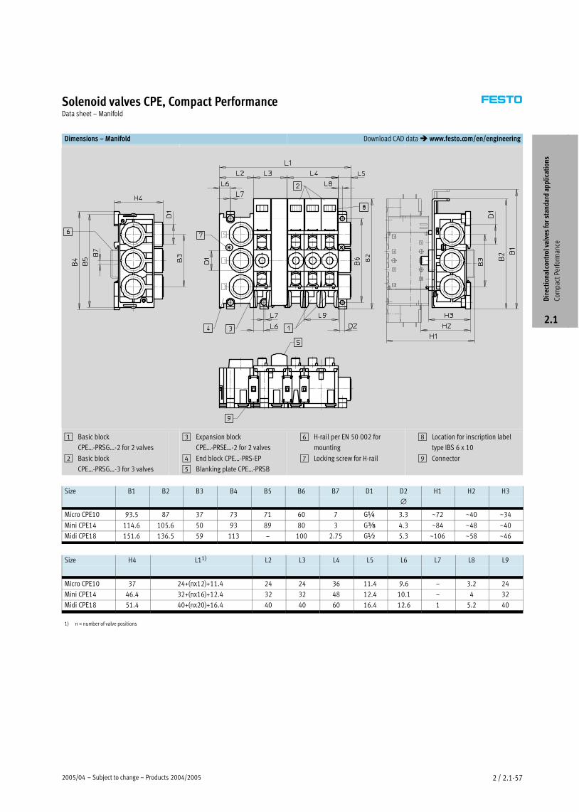
2005/04 – Subject to change – Products 2004/2005 2 / 2.1−57
Solenoid valves CPE, Compact PerformanceData sheet – Manifold
Dimensions – Manifold Download CAD data � www.festo.com/en/engineering
1 Basic block
CPEĪ−PRSGĪ−2 for 2 valves
2 Basic block
CPEĪ−PRSGĪ−3 for 3 valves
3 Expansion block
CPEĪ−PRSEĪ−2 for 2 valves
4 End block CPEĪ−PRS−EP
5 Blanking plate CPEĪ−PRSB
6 H−rail per EN 50 002 for
mounting
7 Locking screw for H−rail
8 Location for inscription label
type IBS 6 x 10
9 Connector
Size B1 B2 B3 B4 B5 B6 B7 D1 D2 H1 H2 H3
∅
Micro CPE10 93.5 87 37 73 71 60 7 G¼ 3.3 ~72 ~40 ~34
Mini CPE14 114.6 105.6 50 93 89 80 3 Gy 4.3 ~84 ~48 ~40
Midi CPE18 151.6 136.5 59 113 – 100 2.75 G½ 5.3 ~106 ~58 ~46
Size H4 L11) L2 L3 L4 L5 L6 L7 L8 L9
Micro CPE10 37 24+(nx12)+11.4 24 24 36 11.4 9.6 – 3.2 24
Mini CPE14 46.4 32+(nx16)+12.4 32 32 48 12.4 10.1 – 4 32
Midi CPE18 51.4 40+(nx20)+16.4 40 40 60 16.4 12.6 1 5.2 40
1) n = number of valve positions
Dir
ecti
onal
con
trol
val
ves
for
stan
dard
app
lica
tion
s
Com
pact
Per
form
ance
2.1
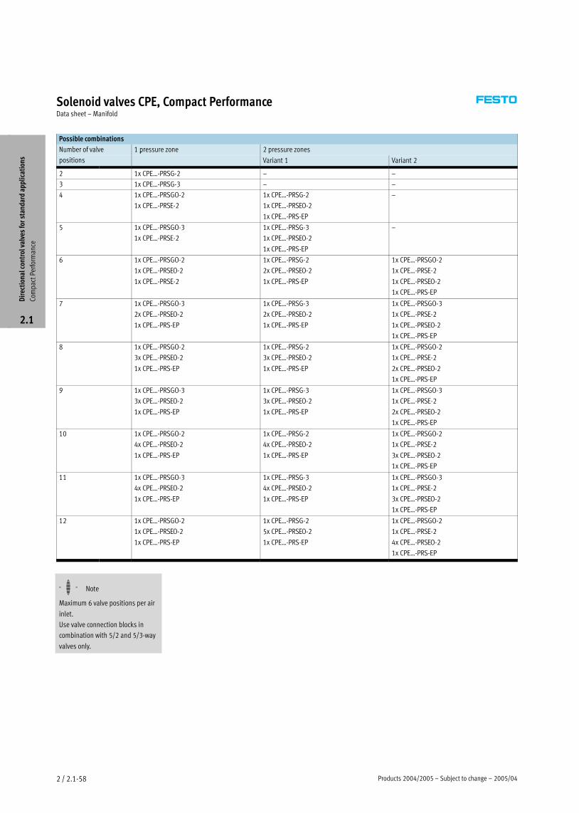
Products 2004/2005 – Subject to change – 2005/042 / 2.1−58
Solenoid valves CPE, Compact PerformanceData sheet – Manifold
Possible combinations
Number of valve 1 pressure zone 2 pressure zones
positions
p
Variant 1 Variant 2
2 1x CPEĪ−PRSG−2 – –
3 1x CPEĪ−PRSG−3 – –
4 1x CPEĪ−PRSGO−2
1x CPEĪ−PRSE−2
1x CPEĪ−PRSG−2
1x CPEĪ−PRSEO−2
1x CPEĪ−PRS−EP
–
5 1x CPEĪ−PRSGO−3
1x CPEĪ−PRSE−2
1x CPEĪ−PRSG−3
1x CPEĪ−PRSEO−2
1x CPEĪ−PRS−EP
–
6 1x CPEĪ−PRSGO−2
1x CPEĪ−PRSEO−2
1x CPEĪ−PRSE−2
1x CPEĪ−PRSG−2
2x CPEĪ−PRSEO−2
1x CPEĪ−PRS−EP
1x CPEĪ−PRSGO−2
1x CPEĪ−PRSE−2
1x CPEĪ−PRSEO−2
1x CPEĪ−PRS−EP
7 1x CPEĪ−PRSGO−3
2x CPEĪ−PRSEO−2
1x CPEĪ−PRS−EP
1x CPEĪ−PRSG−3
2x CPEĪ−PRSEO−2
1x CPEĪ−PRS−EP
1x CPEĪ−PRSGO−3
1x CPEĪ−PRSE−2
1x CPEĪ−PRSEO−2
1x CPEĪ−PRS−EP
8 1x CPEĪ−PRSGO−2
3x CPEĪ−PRSEO−2
1x CPEĪ−PRS−EP
1x CPEĪ−PRSG−2
3x CPEĪ−PRSEO−2
1x CPEĪ−PRS−EP
1x CPEĪ−PRSGO−2
1x CPEĪ−PRSE−2
2x CPEĪ−PRSEO−2
1x CPEĪ−PRS−EP
9 1x CPEĪ−PRSGO−3
3x CPEĪ−PRSEO−2
1x CPEĪ−PRS−EP
1x CPEĪ−PRSG−3
3x CPEĪ−PRSEO−2
1x CPEĪ−PRS−EP
1x CPEĪ−PRSGO−3
1x CPEĪ−PRSE−2
2x CPEĪ−PRSEO−2
1x CPEĪ−PRS−EP
10 1x CPEĪ−PRSGO−2
4x CPEĪ−PRSEO−2
1x CPEĪ−PRS−EP
1x CPEĪ−PRSG−2
4x CPEĪ−PRSEO−2
1x CPEĪ−PRS−EP
1x CPEĪ−PRSGO−2
1x CPEĪ−PRSE−2
3x CPEĪ−PRSEO−2
1x CPEĪ−PRS−EP
11 1x CPEĪ−PRSGO−3
4x CPEĪ−PRSEO−2
1x CPEĪ−PRS−EP
1x CPEĪ−PRSG−3
4x CPEĪ−PRSEO−2
1x CPEĪ−PRS−EP
1x CPEĪ−PRSGO−3
1x CPEĪ−PRSE−2
3x CPEĪ−PRSEO−2
1x CPEĪ−PRS−EP
12 1x CPEĪ−PRSGO−2
1x CPEĪ−PRSEO−2
1x CPEĪ−PRS−EP
1x CPEĪ−PRSG−2
5x CPEĪ−PRSEO−2
1x CPEĪ−PRS−EP
1x CPEĪ−PRSGO−2
1x CPEĪ−PRSE−2
4x CPEĪ−PRSEO−2
1x CPEĪ−PRS−EP
Dir
ecti
onal
con
trol
val
ves
for
stan
dard
app
lica
tion
s
Com
pact
Per
form
ance
2.1
−H− Note
Maximum 6 valve positions per air
inlet.
Use valve connection blocks in
combination with 5/2 and 5/3−way
valves only.
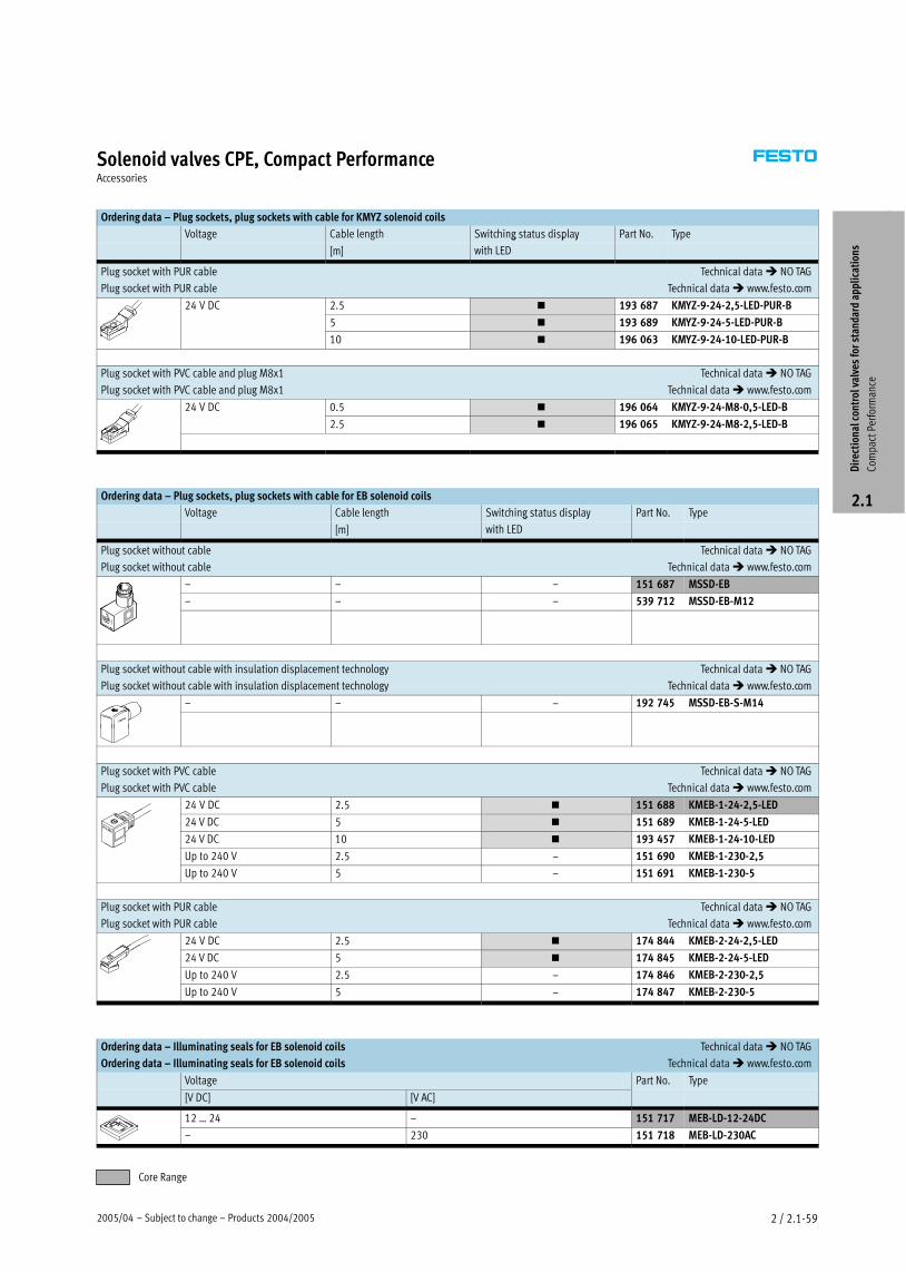
2005/04 – Subject to change – Products 2004/2005 2 / 2.1−59
Solenoid valves CPE, Compact PerformanceAccessories
Ordering data – Plug sockets, plug sockets with cable for KMYZ solenoid coils
Voltage Cable length Switching status display Part No. Type
[m]
g p y
with LED
Plug socket with PUR cable Technical data � NO TAG
Plug socket with PUR cable Technical data � www.festo.com
24 V DC 2.5 � 193 687 KMYZ−9−24−2,5−LED−PUR−B
5 � 193 689 KMYZ−9−24−5−LED−PUR−B
10 � 196 063 KMYZ−9−24−10−LED−PUR−B
Plug socket with PVC cable and plug M8x1 Technical data � NO TAG
Plug socket with PVC cable and plug M8x1 Technical data � www.festo.com
24 V DC 0.5 � 196 064 KMYZ−9−24−M8−0,5−LED−B
2.5 � 196 065 KMYZ−9−24−M8−2,5−LED−B
Ordering data – Plug sockets, plug sockets with cable for EB solenoid coils
Voltage Cable length Switching status display Part No. Type
[m]
g p y
with LED
Plug socket without cable Technical data � NO TAG
Plug socket without cable Technical data � www.festo.com
– – – 151 687 MSSD−EB
– – – 539 712 MSSD−EB−M12
Plug socket without cable with insulation displacement technology Technical data � NO TAG
Plug socket without cable with insulation displacement technology Technical data � www.festo.com
– – – 192 745 MSSD−EB−S−M14
Plug socket with PVC cable Technical data � NO TAG
Plug socket with PVC cable Technical data � www.festo.com
24 V DC 2.5 � 151 688 KMEB−1−24−2,5−LED
24 V DC 5 � 151 689 KMEB−1−24−5−LED
24 V DC 10 � 193 457 KMEB−1−24−10−LED
Up to 240 V 2.5 – 151 690 KMEB−1−230−2,5
Up to 240 V 5 – 151 691 KMEB−1−230−5
Plug socket with PUR cable Technical data � NO TAG
Plug socket with PUR cable Technical data � www.festo.com
24 V DC 2.5 � 174 844 KMEB−2−24−2,5−LED
24 V DC 5 � 174 845 KMEB−2−24−5−LED
Up to 240 V 2.5 – 174 846 KMEB−2−230−2,5
Up to 240 V 5 – 174 847 KMEB−2−230−5
Ordering data – Illuminating seals for EB solenoid coils Technical data � NO TAG
Ordering data – Illuminating seals for EB solenoid coils Technical data � www.festo.com
Voltage Part No. Type
[V DC] [V AC]
12 Ī 24 – 151 717 MEB−LD−12−24DC
– 230 151 718 MEB−LD−230AC
Dir
ecti
onal
con
trol
val
ves
for
stan
dard
app
lica
tion
s
Com
pact
Per
form
ance
2.1
Core Range

Products 2004/2005 – Subject to change – 2005/042 / 2.1−60
Solenoid valves CPE, Compact PerformanceAccessories
Ordering data – General accessories
Part No. Type
Push−in/threaded fittings QS
��Volume 3
� www.festo.com
Silencer
for M3 thread 163 978 U−M3
for M5 thread 165 003 UC−M5
for M7 thread 161 418 UC−M7
for Gx thread 161 419 UC−x
for G¼ thread 165 004 UC−¼
Manual override facility
for KMYZ coils 157 600 AHB−MZB
for EB coils 157 601 AHB−MEB
Inscription labels
18 576 IBS−6x10
Dir
ecti
onal
con
trol
val
ves
for
stan
dard
app
lica
tion
s
Com
pact
Per
form
ance
2.1
Core RangeCore Range