Embed Size (px)
Citation preview
SUPERFUND VAPOR INTRUSION FAQs
February 2012
Superfund Vapor Intrusion FAQs
Page i
CONTENTS Section Page NOTICE/DISCLAIMER .................................................................................................................................. iv ACKNOWLEDGMENT .................................................................................................................................. v ACRONYMS ................................................................................................................................................. vi INTRODUCTION ........................................................................................................................................... 1
A. GENERAL VI CONCEPTS ................................................................................................. 1 A.1 What is VI? ............................................................................................................. 1 A.2 What chemicals pose a VI risk? ............................................................................. 2 A.3 Why is VI a potential concern? .............................................................................. 3 A.4 How do VOC vapors from subsurface sources migrate indoors? What are the
pathways or conduits for vapor migration? ............................................................ 3 A.5 How is the VI pathway different from other exposure pathways? .......................... 4 A.6 What is the “multiple lines of evidence approach” and how is it useful in
assessing the VI pathway? .................................................................................... 5 B. COMMUNITY INVOLVEMENT AND COMMUNICATION .................................................. 6
B.1 What are ways to inform a community about VI concerns and the EPA’s plans to collect samples, and when should that be done? .................................................. 6
B.2 How should building owners or renters be notified of sampling results and whether a VI mitigation system is needed? ........................................................... 7
B.3 How should property value concerns for current and prospective property owners be addressed? ....................................................................................................... 7
B.4 What attempts should be made to get access from reluctant home or building owners/renters for a VI investigation or mitigation and how are attempts for access documented? ............................................................................................. 8
B.5 What options are there to track ownership changes for owner-occupied residences that did not provide access? ................................................................ 8
B.6 How can the EPA foster opportunities for community stakeholders to participate in the VI assessment and mitigation decision process? ........................................ 8
C. SITE SCREENING, INVESTIGATION, and ASSESSMENT .............................................. 9 C.1 How should an initial VI screening be conducted? ................................................ 9 C.2 Is there a generally accepted VI investigation sampling strategy? ...................... 10 C.3 How many houses or buildings should be sampled? Which ones? ..................... 14 C.4 What is the duration of the vapor sampling event?.............................................. 14 C.5 What are the contributors to temporal variability in the sampling results? .......... 15 C.6 How many rounds of sampling are needed to support a risk assessment or public
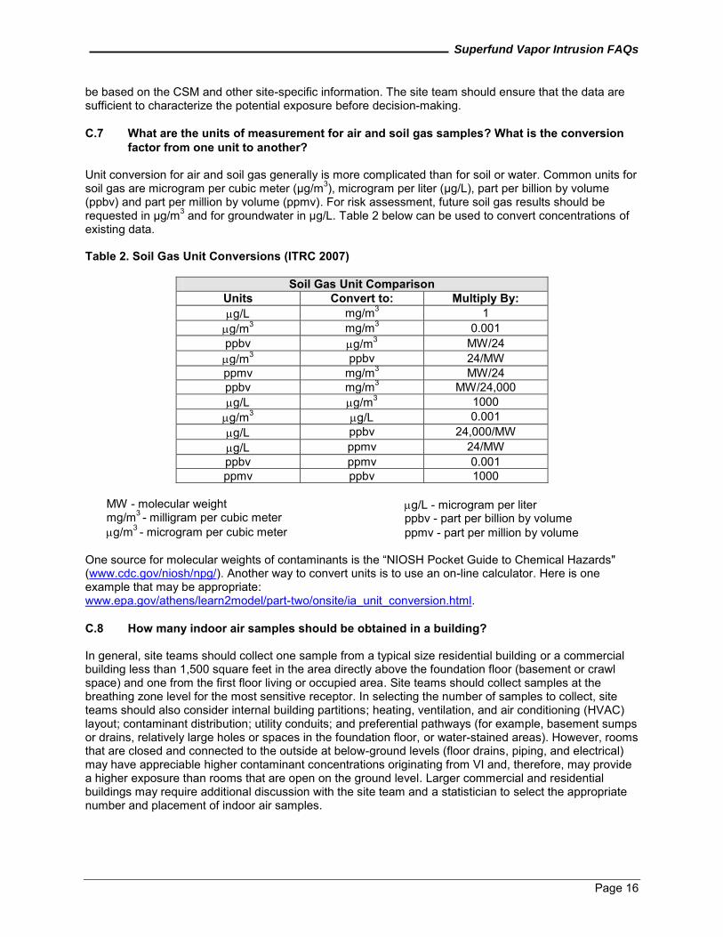
health evaluation for decision-making? ............................................................... 15 C.7 What are the units of measurement for air and soil gas samples? What is the
conversion factor from one unit to another? ........................................................ 16 C.8 How many indoor air samples should be obtained in a building? ........................ 16 C.9 What information should be gathered prior to sampling indoor air in
residential/commercial buildings? ........................................................................ 17 C.10 Is it necessary to remove indoor sources before crawlspace, sub-slab, or indoor
air samples are collected? ................................................................................... 17 C.11 Should the site team collect ambient (outdoor) air samples? .............................. 18 C.12 How many sub-slab samples are recommended per building? ........................... 18 C.13 Are there other special considerations when conducting sub-slab sampling? .... 19 C.14 What type of sampling is appropriate when there is a partial basement or dirt
floor in the basement? ......................................................................................... 19 C.15 What about sampling soil gas during or soon after significant rainfall? ............... 19 C.16 How should soil gas samples be collected when access is denied for sub-slab
sampling? ............................................................................................................. 20 C.17 Should additional sampling be considered if a building already has a radon
mitigation system installed and functioning? ....................................................... 20 C.18 How is a site assessed for VI when no buildings are present? ........................... 20
Superfund Vapor Intrusion FAQs
CONTENTS (Continued)
D. DATA EVALUATION ......................................................................................................... 20 D.1 How do I determine whether the VI pathway is complete? How do I determine
whether measured indoor air concentrations can be reasonably attributed to VI? .................................................................................................................... 20
D.2 Are there updates to the screening tables in the 2002 draft VI guidance? .......... 21 D.3 What is the vapor attenuation factor? .................................................................. 22 D.4 What are OSWER's recommended conservative generic screening level
attenuation factors? ............................................................................................. 23 D.5 Can modeling be used to assess the VI pathway? .............................................. 23
E. SAMPLING & ANALYSES ................................................................................................ 24 E.1 What sample collection techniques are available? .............................................. 24 E.2 When sampling, what factors should be considered? ......................................... 26 E.3 Can mobile laboratory data be used for VI investigations? What about a field-
portable gas chromatograph/mass spectrometer (GC/MS)? ............................... 27 E.4 Should tracer gas be used to test for leakage when sub-slab sampling is
conducted? ........................................................................................................... 27 F. RISK ASSESSMENT ........................................................................................................ 28
F.1 What are some of the important considerations in conducting a risk assessment for VI? ................................................................................................................... 28
F.2 Should the site manager be concerned about differences in exposure and sampling duration? ............................................................................................... 30
F.3 What is the current approach for assessing sites that contain TCE? .................. 30 F.4 How should risk assessors evaluate chemicals for which no inhalation toxicity
values (for example, RfCs and IURs) are available? ........................................... 31 F.5 Should risks be calculated for adults and children separately? ........................... 31 F.6 Is it appropriate to use Occupational Safety and Health Administration (OSHA)
standards in the Superfund program to evaluate worker risk associated with VI? ................................................................................................................ 31
F.7 What is the EPA’s position when VI is a potential concern in a non-residential setting? ................................................................................................................. 31
G. MITIGATION – DESIGN AND OPERATION .................................................................... 32 G.1 What are the primary considerations for evaluating a VI mitigation approach? .. 32 G.2 What mitigation approaches are effective? Under what conditions? ................... 33 G.3 What is the difference between a construction vapor barrier and a VI barrier? .. 35 G.4 What diagnostic measurements should be used to select and design a mitigation
system? ................................................................................................................ 35 G.5 What short-term measures generally are appropriate to ensure proper
installation? .......................................................................................................... 36 G.6 Does a building need a VI mitigation system if it already has a radon mitigation
system installed and functioning? ........................................................................ 36 G.7 What ICs or post-removal site controls should be considered to ensure long-term
protectiveness of the VI remedy? ........................................................................ 36 H. POST-CONSTRUCTION MANAGEMENT ....................................................................... 37
H.1 What does operation and maintenance entail for a typical VI mitigation system? ................................................................................................................ 37
H.2 How is the Operational and Functional (O&F) determination made for VI mitigation systems? ............................................................................................. 37
H.3 How is the start of O&M for VI mitigation systems determined? ......................... 38 H.4 How is long-term O&M managed for non-NPL removal sites? ............................ 38
REFERENCES ............................................................................................................................................ 39 ADDITIONAL RESOURCES ....................................................................................................................... 42
Page ii
Superfund Vapor Intrusion FAQs
CONTENTS (Continued) APPENDICES A EPA CONTACTS B CONVERSION OF HENRY’S LAW COEFFICIENTS C ANALYTICAL METHODS
FIGURES Figure Page 1. Vapor Intrusion Pathway (EPA 2008a) ............................................................................................ 2 2. Types of Sampling Equipment (from left to right: Canisters, Tedlar Bags, and Sorbent Tubes)
(EPA 2008a) ................................................................................................................................... 24 3a. Conceptual Vapor Intrusion Mitigation System (EPA 2008a) ........................................................ 34 3b. Actual Vapor Intrusion Mitigation System (ITRC 2007) ................................................................. 34
TABLES Table Page 1. Advantages and Disadvantages Associated with Sampling Types ............................................... 13 2. Soil Gas Unit Conversions (ITRC 2007) ........................................................................................ 16 3. Comparison of Canisters and Tedlar Bags (Air Toxics 2011)........................................................ 26 4. Some Key Advantages and Disadvantages of Tracers (ITRC 2007) ............................................ 28
Page iii
Superfund Vapor Intrusion FAQs
Page iv
NOTICE/DISCLAIMER This document was developed through the cooperative efforts of a team of EPA Headquarters and regional staff inside the EPA and relies on peer-reviewed literature, EPA reports, Web sources, current research, and other pertinent information. This document has been through a thorough internal EPA peer-review process, which included comments from Office of Solid Waste and Emergency Response (OSWER) offices, Office of General Counsel, and the VI Forum. References and Web links are provided for readers interested in additional information; these Web links, verified as accurate at the time of publication, are subject to change by Web sponsors. Note that the mention of trade names or commercial products does not constitute endorsement or recommendation for use.
Superfund Vapor Intrusion FAQs
Page v
ACKNOWLEDGMENT This document was prepared for EPA’s Office of Superfund Remediation and Technology Innovation under contract number EP-W-07-078. Special acknowledgement is given to the federal staff for providing extensive input to this document. Their cooperation and willingness to share their expertise about vapor intrusion issues will assist remedial project managers (RPMs) and on-scene coordinators (OSCs) encountering such issues in the field. Contributors to the report included: EPA Office of Superfund Remediation and Technology Innovation - David Bartenfelder, David Crawford, Helen Dawson, and Mike Hurd EPA Region 1 - Meghan Cassidy, Alex Sherrin EPA Region 2 - Angela Carpenter, Michael Sivak EPA Region 3 - Jack Kelly EPA Region 7 - Mary Peterson EPA Region 9 - Alana Lee EPA Policy Analysis and Resource Management - Stiven Foster EPA Office of Resource Conservation and Recovery - Henry Schuver EPA Environmental Response Team - Dave Mickunas EPA Office of Emergency Management - John Irizarry EPA Office of Brownfields and Land Revitalization - Ann Carroll EPA Federal Facilities Reuse and Restoration Office - Mary Cooke
Superfund Vapor Intrusion FAQs
Page vi
ACRONYMS AF Attenuation factor AFss Sub-slab to indoor air AFssg Shallow soil gas to indoor air AFdsg Deep soil gas to indoor air AFgw Groundwater to indoor air AEHS Association for the Environmental Health and Sciences ARAR Applicable or relevant and appropriate requirement ASD Active soil depressurization atm Atmosphere atm m3 mol-1 Atmosphere-meter cubed per mole BTEX Benzene, toluene, ethylbenzene, xylene Cindoor Contaminant concentration in indoor air Cgw Contaminant concentration in groundwater Csoilgas Contaminant concentration in soil gas CERCLA Comprehensive Environmental Response, Compensation, and Liability Act CFR Code of Federal Regulations CIC Community involvement coordinator CLU-IN Hazardous Waste Clean-Up Information COC Contaminant of concern CSM Conceptual site model DCE Dichloroethene DoD Department of Defense DQO Data quality objective DTSC California Department of Toxic Substances Control ED Exposure duration EPA U.S. Environmental Protection Agency ERT Environmental Response Team ESD Explanation of Significant Difference FAQ Frequently asked question FEM Forum on Environmental Measures GC/MS Gas chromatograph/mass spectrometer g/mol Grams per mole HDPE High-density polyethylene Hg Mercury HI Hazard index HQ Hazard quotient HVAC Heating, ventilation, and air conditioning IC Institutional control IRIS Integrated Risk Information System ITRC Interstate Technology and Regulatory Council IUR Inhalation unit risk J&E Johnson and Ettinger
Superfund Vapor Intrusion FAQs
ACRONYMS (Continued) L Liter
3 L/m Liter per cubic meter LEL Lower explosive limit LTRA Long-term response action µg/L Microgram per liter
3µg/m Microgram per cubic meter MCL Maximum contaminant level
3mg/m Milligram per cubic meter MIP Membrane interface probe mm Millimeter MMOA Mutagenic mode of action MS Mass spectroscopy NA Not applicable NAPL Non-aqueous phase liquid NCP National Oil and Hazardous Substances Pollution Contingency Plan NIOSH National Institute of Occupational Safety and Health NJDEP New Jersey Department of Environmental Protection NPL National Priorities List NYDEC New York Department of Environmental Conservation O&F Operational and functional O&M Operation and maintenance OSC On-scene coordinator OSHA Occupational Safety and Health Administration OSWER Office of Solid Waste and Emergency Response Pa Pascal PCB Polychlorinated biphenyl PCE Tetrachloroethene PID Photoionization detector ppb Part per billion ppbv Part per billion by volume ppmv Part per million by volume pptv Part per trillion by volume PRP Potentially responsible party PRSC Post-removal site controls PSV Passive soil ventilation QAPP Quality assurance project plan RAGS Risk Assessment Guidance for Superfund RAO Remedial action objective RCRA Resource Conservation and Recovery Act RfC Reference concentration ROD Record of decision RPM Remedial project manager RSL Regional screening level RWQCB Regional Water Quality Control Board
Page vii
Superfund Vapor Intrusion FAQs
ACRONYMS (Continued)
Page viii
SIM Selected ion monitoring SOP Standard operating procedure SSD Sub-slab depressurization STSC Superfund Health Risk Technical Support Center TAGA Trace Atmospheric Gas Analyzer TBC To-be-considered criteria TCE Trichloroethene UNK Unknown UST Underground storage tank VDPE Very low-density polyethylene VI Vapor intrusion VISL Vapor Intrusion Screening Level Calculator VOC Volatile organic compound
Superfund Vapor Intrusion FAQs
Page 1
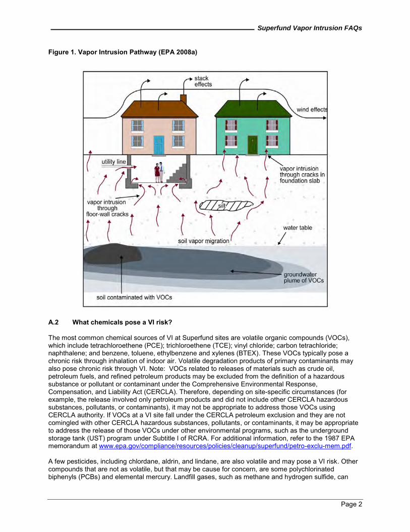
INTRODUCTION This document is a collection of Frequently Asked Questions (FAQ) about vapor intrusion (VI) at Superfund sites. These FAQs provide information and recommendations based on experiences garnered over the last few years in addressing VI at Superfund remedial and removal sites and cleanup undertaken using other authorities. Although this document is primarily geared toward the Superfund Program, other U.S. Environmental Protection Agency cleanup programs, such as the Resource Conservation and Recovery Act (RCRA), may find it helpful to consider parts of the FAQs for their own specific needs. The primary purpose of this document is to help Superfund site managers (Remedial Project Managers [RPMs] and On-Scene Coordinators [OSCs]) understand some of the key concepts related to assessment and mitigation of the VI pathway and to help foster consistency in technical approach as much as possible. These FAQs are designed to be a resource tool for Superfund site managers that brings together information from various sources and provides recommendations for dealing with common VI issues. These recommendations, however, are intended to be flexible enough to account for variations in site-specific conditions and allow the use of new approaches as they become available. Numerous information sources are referenced throughout the document, as appropriate. Two documents, in particular, are cited frequently: (1) Interstate Technology and Regulatory Council’s (ITRC) Vapor Intrusion Pathway: A Practical Guideline, January 2007 (ITRC 2007) and (2) Department of Defense (DoD) Vapor Intrusion Handbook, January 2009 (DoD 2009). While the EPA may not support all aspects of these reports, they contain many useful ideas and applications that may be helpful to the EPA site managers. These documents are included because they are publicly available, developed by large groups, and may be useful in appropriate circumstances as common-sense guides for VI. Additionally, the EPA’s draft guidance on VI, OSWER Draft Guidance for Evaluating the Vapor Intrusion to Indoor Air Pathway from Groundwater and Soils (Subsurface Vapor Intrusion Guidance), EPA-530-D-02-004, November 2002 (EPA 2002) is referenced, as appropriate. Even though the state of the science has changed since the draft guidance was issued in 2002, the document contains useful information that is still relevant for vapor intrusion investigations. A. GENERAL VI CONCEPTS A.1 What is VI? VI is the general term given to the migration of volatile chemicals from subsurface contaminated soils and groundwater into the indoor air spaces of overlying buildings through openings in the building foundation (for example, cracks and utility openings), as illustrated in Figure 1 below (Johnson and Ettinger 1991). A key concept of VI is that the vapor concentrations attenuate (decrease) as the vapors migrate. The attenuation occurs as a result of the processes that control vapor migration in soil (for example, diffusion, advection, sorption, and potentially degradation), coupled with the dilution that results when the vapors enter a building and mix with indoor air. The term “attenuation factor,” defined as the ratio of indoor air concentration to subsurface concentration, is used as a measure of the decrease in concentration that occurs during vapor migration and may vary with space and time.
Superfund Vapor Intrusion FAQs
Page 2
Figure 1. Vapor Intrusion Pathway (EPA 2008a)
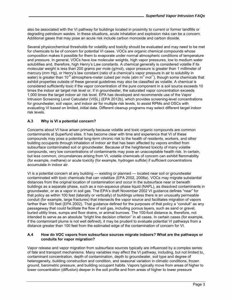
A.2 What chemicals pose a VI risk? The most common chemical sources of VI at Superfund sites are volatile organic compounds (VOCs), which include tetrachloroethene (PCE); trichloroethene (TCE); vinyl chloride; carbon tetrachloride; naphthalene; and benzene, toluene, ethylbenzene and xylenes (BTEX). These VOCs typically pose a chronic risk through inhalation of indoor air. Volatile degradation products of primary contaminants may also pose chronic risk through VI. Note: VOCs related to releases of materials such as crude oil, petroleum fuels, and refined petroleum products may be excluded from the definition of a hazardous substance or pollutant or contaminant under the Comprehensive Environmental Response, Compensation, and Liability Act (CERCLA). Therefore, depending on site-specific circumstances (for example, the release involved only petroleum products and did not include other CERCLA hazardous substances, pollutants, or contaminants), it may not be appropriate to address those VOCs using CERCLA authority. If VOCs at a VI site fall under the CERCLA petroleum exclusion and they are not comingled with other CERCLA hazardous substances, pollutants, or contaminants, it may be appropriate to address the release of those VOCs under other environmental programs, such as the underground storage tank (UST) program under Subtitle I of RCRA. For additional information, refer to the 1987 EPA memorandum at www.epa.gov/compliance/resources/policies/cleanup/superfund/petro-exclu-mem.pdf. A few pesticides, including chlordane, aldrin, and lindane, are also volatile and may pose a VI risk. Other compounds that are not as volatile, but that may be cause for concern, are some polychlorinated biphenyls (PCBs) and elemental mercury. Landfill gases, such as methane and hydrogen sulfide, can
Superfund Vapor Intrusion FAQs
Page 3
also be associated with the VI pathway for buildings located in proximity to current or former landfills or degrading petroleum wastes. In these situations, acute inhalation and explosion risks can be a concern. Additional gases that may pose an acute risk include carbon monoxide and carbon dioxide. Several physicochemical thresholds for volatility and toxicity should be evaluated and may need to be met for chemicals to be of concern for potential VI cases. VOCs are organic chemical compounds whose composition makes it possible for them to evaporate under normal atmospheric conditions of temperature and pressure. In general, VOCs have low molecular weights, high vapor pressures, low to medium water solubilities and, therefore, high Henry’s Law constants. A chemical generally is considered volatile if its molecular weight is less than 200 grams per mole (g/mol), vapor pressure is greater than 1 millimeter of mercury (mm Hg), or Henry’s law constant (ratio of a chemical’s vapor pressure in air to solubility in water) is greater than 10-5 atmosphere-meter cubed per mole (atm m3 mol-1), though some chemicals that exhibit properties outside of these general guidelines may also be classified as volatile. A chemical is considered sufficiently toxic if the vapor concentration of the pure component in a soil source exceeds 10 times the indoor air target risk level or, if in groundwater, the saturated vapor concentration exceeds 1,000 times the target indoor air risk level. EPA has developed and recommends use of the Vapor Intrusion Screening Level Calculator (VISL) (EPA 2012b), which provides screening-level concentrations for groundwater, soil vapor, and indoor air for multiple risk levels, to assist RPMs and OSCs with evaluating VI based on limited, initial data. Different cleanup programs may select different target indoor risk levels. A.3 Why is VI a potential concern? Concerns about VI have arisen primarily because volatile and toxic organic compounds are common contaminants at Superfund sites. It has become clear with time and experience that VI of these compounds may pose a potential long-term chronic risk to the health of residents, workers, and other building occupants through inhalation of indoor air that has been affected by vapors emitted from subsurface contaminated soil or groundwater. Because of the heightened toxicity of many volatile compounds, very low concentrations of contaminants may pose an unacceptable health risk. In certain, but less common, circumstances arising from VI, volatile chemicals of concern can exhibit flammability (for example, methane) or acute toxicity (for example, hydrogen sulfide) if sufficient concentrations accumulate in indoor air. VI is a potential concern at any building — existing or planned — located near soil or groundwater contaminated with toxic chemicals that can volatilize (EPA 2002, 2008a). VOCs may migrate substantial distances from the original location of contamination and occur in the subsurface near or beneath buildings as a separate phase, such as a non-aqueous phase liquid (NAPL), as dissolved contaminants in groundwater, or as a vapor in soil gas. The EPA’s draft November 2002 VI guidance defines “near” for that policy as within 100 feet (laterally or vertically) of buildings unless there is an unusually permeable conduit (for example, large fractures) that intersects the vapor source and facilitates migration of vapors farther than 100 feet (EPA 2002). That guidance defined for the purposes of that policy a “conduit” as any passageway that could facilitate the flow of soil gas, including porous layers, such as sand or gravel, buried utility lines, sumps and floor drains, or animal burrows. The 100-foot distance is, therefore, not intended to serve as an absolute “bright line decision criterion” in all cases. In certain cases (for example, if the contaminant plume is not well defined), it may be prudent to evaluate potential VI pathways from a distance greater than 100 feet from the estimated edge of the contamination of concern for VI. A.4 How do VOC vapors from subsurface sources migrate indoors? What are the pathways or
conduits for vapor migration? Vapor release and vapor migration from subsurface sources typically are influenced by a complex series of fate and transport mechanisms. Many variables may affect the VI pathway, including, but not limited to, contaminant concentration, depth of contamination, depth to groundwater, soil type and degree of heterogeneity, building construction and condition, and seasonal variation in climatic conditions, frozen ground, barometric pressure, and building occupant habits. Vapors typically move from areas of higher to lower concentration (diffusion) deeper in the soil profile and from areas of higher to lower pressure
Superfund Vapor Intrusion FAQs
Page 4
(advection) near the soil surface and beneath and around buildings. Once these vapors are present near or beneath buildings, they may accumulate beneath the buildings and can migrate upward into the building with soil gas. Pressure differences between the soil environment and buildings can cause vapors to move from the soil through foundation cracks or openings. The vapors can be swept inside buildings if there are cracks or other openings in the sub-grade walls or foundations of the building, specifically a sump hole or interior French drain, as building pressures are commonly lower than in the subsurface. This common pressure difference within buildings is known as a “stack effect,” and it is an important contributor to VI. Heating systems, strong winds, and basements can enhance the stack effect of a building. Also note that it is possible for indoor air to migrate downward into the subsurface if the pressure difference is great enough. Vapors have also been observed to migrate through what appears to be intact concrete floors and walls, but that may in fact have small unobserved fractures or porous areas from improper curing. Vapors can also migrate laterally along a preferential pathway, such as a utility corridor, within the more porous layers of soil, or beneath frozen ground, asphalt, or other barriers where vapors cannot escape (EPA 2002, 2008a). In general, the site team should develop a conceptual site model (CSM) of the primary fate and transport processes that may contribute to VI at a specific site, which would be useful in guiding the remedial investigation (for example, identifying buildings that may be subject to VI) and identifying appropriate remedial action objectives (RAOs) for groundwater and soil (that is, above and beyond any building-specific vapor mitigation). Note that there may be situations based on the CSM where not all media are relevant to the evaluation of VI (such as deep groundwater or uncontaminated groundwater). Generally, it is important to identify the nature and extent of potential sources of volatile compounds in the subsurface, whether as NAPL, dissolved in groundwater, or adsorbed to soil solids or in soil moisture. NAPL migration is particularly complex. The site team should give particular attention to understanding the subsurface geology when NAPLs, such as petroleum fuel products, PCE, TCE, and elemental mercury, are present because these NAPLs can migrate independently of groundwater movement and can exhibit other unique transport behaviors. A.5 How is the VI pathway different from other exposure pathways? The VI pathway presents unique challenges compared with other potential pathways of human exposure to environmental contaminants. VI affects indoor air, which is the air that people breathe for the most hours each day. Whereas the risks posed by potential ingestion and skin exposures to contaminated groundwater and soil can be mitigated by personally avoiding contact with these media, individuals cannot avoid exposures to indoor air in their homes or workplaces, if contaminated vapors are present. While contaminated soils can be removed to minimize exposure and alternative water supplies can be provided, it is not possible for occupants to discontinue breathing contaminated air and it is not practical to provide an alternative breathing supply. Additional challenges with this pathway include risk mitigation, sampling, and assessment. Although the actions taken to characterize and clean up contaminated soil, groundwater, or even ambient air may be apparent to the community; they typically are not invasive to the personal lives of individuals. Resolving VI, on the other hand, may involve collecting environmental samples inside or immediately outside a building. The process of investigating the VI pathway can be intrusive and often directly affects occupants. Assessing the VI pathway can be more complex than assessing other pathways because it typically involves the use of indirect measurements and modeling (for example, using soil gas or groundwater data) to assess the potential for indoor inhalation risks. In addition, consumer and other products found inside the home release ‘background’ VOCs and further complicate the assessment of VI. Additional information about background sources can be found in the EPA’s Background Indoor Air Concentrations of Volatile Organic Compounds in North American Residences (1990-2005): A Compilation of Statistics for Assessing Vapor Intrusion, EPA 30-R-10-001, June 2011 (www.epa.gov/oswer/vaporintrusion/documents/oswer-vapor-intrusion-background-Report-062411.pdf).
Superfund Vapor Intrusion FAQs
Page 5
A.6 What is the “multiple lines of evidence approach” and how is it useful in assessing the VI pathway?
The VI pathway can be complex. As a result, EPA recommends that a comprehensive assessment of this pathway be based on several lines of evidence, and that generally, this assessment should be conducted to help the site team evaluate whether this pathway may pose unacceptable risks at a specific site. In addition, coordination with a risk assessor and hydrogeologist generally should be useful in evaluating the VI pathway. Considerable information, primarily empirical field data, has been generated regarding evaluation of the VI pathway since it emerged as a national issue in the late 1990s and especially since the EPA’s draft VI guidance was published in 2002. The large number of variables affecting the transport of vapors from the subsurface to indoor air and the complex influence of indoor sources of common subsurface contaminants make it preferable, for purposes of accuracy, to evaluate data of more than one type (that is, multiple lines of evidence). Using a multiple lines of evidence approach often is particularly important when screening out sites (that is, determining that no further vapor intrusion investigation or other response action is needed). EPA’s experience with VI investigations indicates that typically no data set for a single medium (for example, groundwater, soil gas, sub-slab gas, or indoor air) is adequate to accurately screen out sites. However, in some cases, a single line of evidence may be significant and support a CERCLA response. In general, therefore, it is recommended that regions collect and evaluate multiple lines of evidence to support decision-making regarding the VI pathway. A number of groups have examined the role of lines of evidence. For example, there generally may be relevant information in ITRC’s 2007 guidance (ITRC 2007) and DoD’s 2009 VI handbook (DoD 2009). Lines of evidence to evaluate the VI pathway may include, but are not limited to, the following:
Source of the contaminants (dry cleaner, mill or gas station, for example). Indoor air data. Sub-slab (or crawl-space) soil gas data. Concurrent outdoor air data. Soil gas data, including some level of vertical and spatial profiling, as appropriate. Groundwater data, including some level of vertical and spatial profiling, as appropriate. Data trends. Background, internal and external, sources. Building construction and current conditions, including utility conduits. Site geology and history. Tracer data. Contaminant ratios. Observed attenuation factors (absolute and relative).
By using the multiple lines of evidence approach, project managers usually have been successful in determining whether the VI exposure pathway is complete and whether any elevated levels of contaminants in indoor air are likely caused by subsurface VI, an indoor source (consumer product), or an outdoor source. Generally, site conditions should indicate which lines of evidence are appropriate and sufficient for decision-making. It generally is not cost-effective to conduct a comprehensive assessment at every site because comprehensive assessments can be time-consuming and expensive and because VI will not necessarily pose an unacceptable risk of exposure or a health concern at every contaminated site. For example, where concentrations in groundwater are low (such as below the maximum contaminant level [MCL]), it may be appropriate for site managers to conclude, in conjunction with other site-specific data, that the VI exposure pathway is not complete. That evaluation, and related data and information, should be included in the administrative record that supports the cleanup decision.
Superfund Vapor Intrusion FAQs
Page 6
It is important to involve the community early in the process of evaluating and investigating the VI pathway. Because community involvement should begin early, the next section discusses Community Involvement before it provides additional information about the VI assessment process. B. COMMUNITY INVOLVEMENT AND COMMUNICATION B.1 What are ways to inform a community about VI concerns and the EPA’s plans to collect
samples, and when should that be done? Community outreach should be initiated as soon as possible after the decision that VI may exist at a particular site (EPA 2001). Informing the community about VI concerns and plans to conduct sampling can be resource intensive. The EPA recommends that site managers work with a Community Involvement Coordinator (CIC) to develop a community outreach strategy to ensure the most appropriate means of communication throughout the process (EPA 1990a, 2005b). Developing fact sheets, question and answer sheets, or other documents is recommended to help educate the public and to facilitate communication. Fact sheets developed by the EPA’s regional offices are posted on the Environmental Science Connector website (www.portal.epa.gov/ESC). Staff should also consider the EPA’s previous involvement at the site, the existence of community or neighborhood groups, and the phase of the regulatory process when VI is being addressed, among other things, in considering the most effective communication strategy. Since assessing the VI pathway may involve some sampling in a home or workplace, the EPA recommends that individual, one-on-one communication with each property owner or renter occur whenever possible. Communication may occur after meetings with a larger audience to introduce the overall issue of VI. After a community meeting, a member of the site team (such as the RPM, OSC, or CIC) can send a letter to each home or building owner or renter explaining the EPA’s plans to collect samples and the EPA’s intent to contact him or her in the near future. The EPA can then begin to contact individual property owners and renters to schedule in-person visits. Building-by-building contact and communication are recommended as the most effective means of educating the community and obtaining access needed to collect samples. Personal contact is further recommended to establish a good working relationship with each home or building owner or renter and to build the trust needed to gain access for sampling. In many instances, local churches, ethnic organizations, and other community groups can be brought in to reach out to affected community members. The initial visit should be conducted as soon as possible and can be used to further explain the EPA’s plans, answer any questions, obtain a signed access agreement, review any instructions for the property owner or renter (for example, keep doors and windows closed during sampling or avoid bringing dry-cleaned clothing indoors during sampling), and perform a general survey of the building to identify likely sources of contaminants (consumer or other products). A date and time for the sampling should be scheduled during the initial visit, if at all possible. Standardized fact sheets can be used to inform home and building owners and renters about potential household products that may be sources of indoor air contamination, as well as steps the property owner or renter and the EPA should take to minimize these sources. This information should be reviewed with the property owner or renter before sampling begins. Some common household products that are sources of indoor air contamination include nail polish remover, paints and paint thinner, wood office furniture (for example, stains, varnishes, sealers, and coatings), dry cleaning, scented candles, and cleaning fluids. Additional examples that may be useful are provided in Section 3.5.4 of the ITRC guidance (ITRC 2007). In addition, Appendix H of the New Jersey Department of Environmental Protection (NJDEP) 2005 VI guidance includes a list of common household sources for indoor air. As an initial screen and to reduce the burden of cooperation on the owner or renter, investigators can focus the identification and removal of household products on those that contain contaminants of concern (COCs) identified in the source of the VI vapors (for example, TCE, PCE, and benzene if present in the source). In addition, the property owner or renter should know that if a VI mitigation system is installed, the system normally is designed to protect the home or building only against chemicals coming from the ground. A VI mitigation system generally will not protect the home against continuing indoor sources because VI mitigation systems typically are not
Superfund Vapor Intrusion FAQs
Page 7
indoor air filtration systems. Usually, it is in the best interest of the property owners or renters to minimize consumer and household products that are sources of indoor air contamination, not just during sampling events, but over the long term as well. Site managers often deal with both owners and renters when there is a need to sample on, in, or under a rental property. There are different legal and communication issues for each. For example, the owner is responsible for granting access for sampling and, if necessary, installation of mitigation measures; however, logistics normally are arranged with the renter, if the owner granted access. Both the owner and the renter should be apprised of VI exposure concerns that have the potential to adversely affect human health, which includes providing sampling results to both parties. Site managers may also need to sample on, in, or under non-residential buildings, such as schools, libraries, hospitals, hotels and stores. These situations may include broader outreach to the public, while maintaining personal contact with the property owner. The site team should also instruct the owners or renters on what the sampling devices are, what they look like, where they will be located, and how to live with the on-going sampling. B.2 How should building owners or renters be notified of sampling results and whether a VI
mitigation system is needed? Generally, the site team should provide validated sampling results to property owners or renters within 30 days after the results have been received (EPA 1990b). Use of real-time or near-real time sampling, such as a field gas chromatograph/mass spectrometer (GC/MS) or Hapsite GC/MS, reduces the delay between the sampling event and receipt of initial results. In such cases, the building owner or renter can view the preliminary results almost immediately and receive the final results after data validation. A transmittal letter should indicate if any future actions are appropriate based on the sampling events. It is important to communicate to property owners and renters that the determination to install a VI mitigation system is based on a calculated risk, which reflects many conservative, health protective factors. The initial notification to owners or renters that their home or building has been selected to receive a VI mitigation system can be delivered in various ways. A primary mechanism is a face-to-face meeting with the building owner or renter to explain the data results and discuss next steps, including installation of a system. Another mechanism is to use the data transmittal letter to provide the notification. In many cases, however, the decision to install mitigation systems will not have been made before the sampling results are transmitted. In these situations, data transmittal letters can be sent conveying the message that the EPA is reviewing all results for the affected area and is considering appropriate next steps. Once the decision document is signed, the site team can develop and mail a fact sheet to all community members in the affected area, followed by a community meeting. If mitigation systems are deemed appropriate, the site team should be prepared to explain the impacts of installing these systems in face-to-face meetings with the property owners or renters. These meetings should include a discussion of whether the property owner or renter will be responsible to pay the electrical cost to operate a mitigation system, which may range from $10 to $20 or more per month. Impacts including the need to remove basement contents to allow installation should also be discussed with the property owner or renter. B.3 How should property value concerns for current and prospective property owners be
addressed? EPA staff generally should avoid discussing subjects outside the scope of Agency authority, for example, property value issues. In general, if asked, it is recommended that Regions suggest that prospective buyers and sellers should speak to real estate professionals and lenders from the local area with questions about property values. If a home owner or renter has questions about mitigation systems, Regions can provide information explaining how the presence of such a system is designed to reduce exposure to chemicals found in indoor air and is intended to avert human health related problems.
Superfund Vapor Intrusion FAQs
Page 8
B.4 What attempts should be made to get access from reluctant home or building owners/renters for a VI investigation or mitigation and how are attempts for access documented?
The number of attempts to obtain access to perform a VI assessment or install a mitigation system should be consistent with regional practice. In general, more than one attempt for access is recommended. All attempts should be documented using telephone conversation records, emails, or letters sent to home or building owners or renters. All requests for access, as well as provision of access, should be made in writing to document the EPA’s efforts to protect human health at the site. If the owner of a rental property refuses access, the EPA may require access in the interest of protecting the occupants, for evaluating the need for response, choosing a response action, taking a response action, or otherwise enforcing CERCLA. Additional information on the Agency’s policy regarding entry and access under CERCLA can be found in the EPA’s Memorandum on Entry and Continued Access under CERCLA (EPA 1987, www.epa.gov/compliance/resources/policies/cleanup/superfund/cont-access-mem.pdf). In addition, the EPA may need to obtain consent from the owner to grant access for rental properties, but also take separate steps to communicate with the tenant about logistics, results of the investigation, and response activities. The EPA preference is to sample and, if called for in a decision document, to install mitigation systems with the owner’s consent in writing as a voluntary action; however, at the region’s discretion under CERCLA, it may be appropriate to issue Section 104(e) letters to reluctant homeowners or to obtain a court order for investigation. Access to owner-occupied residences may be handled differently than commercial buildings or rental properties. EPA should communicate to reluctant homeowners the value and benefits of an assessment and perhaps a mitigation system. Current owners occupying their residences should be advised of what the Record of Decision (ROD) says and that if they choose not to have a vapor mitigation system installed as part of the CERCLA remedial action, they might be responsible for the costs of installing and maintaining their own system if they decide to do so at a later time. In this case, the site manager should work with regional counsel to identify an appropriate approach for documenting a resident's refusal to allow mitigation. B.5 What options are there to track ownership changes for owner-occupied residences that
did not provide access? Site managers should make reasonable attempts to track changes in ownership for owners of homes or buildings who did not provide access for assessment sampling or installation of a mitigation system. Reasonable attempts could include an annual site inspection where homes or buildings for sale can be noted. If changes in ownership are noted, then appropriate follow-up can be conducted with the new property owner. In general, the Agency does not devote major resources to tracking ownership; the appropriate state or local agency, or potentially responsible party (PRP), may be in a better position to track that information. B.6 How can the EPA foster opportunities for community stakeholders to participate in the VI
assessment and mitigation decision process? Community stakeholder involvement is extremely important for sites with vapor intrusion issues, in part because exposures to toxic vapors in homes, workplaces, schools, and places of commerce may be unavoidable. The potential need for access to a personal residence or business to conduct indoor air sampling further heightens the need for community trust and acceptance. Consequently, there should be community stakeholder involvement from the earliest stage of the site assessment and risk assessment process, with on-going education, communication and discussion throughout the entire process. CERCLA and EPA regulations require that specific community involvement activities must occur at certain points throughout the Superfund process (40 Code of Federal Regulations [CFR] §300.155). In 2005, OSWER released the Community Involvement Handbook (EPA 540-K-05-003), which presents legal and policy requirements for Superfund community involvement and additional suggestions for involving the
Superfund Vapor Intrusion FAQs
Page 9
community in the Superfund process (EPA 2005b). In addition, the EPA Guidelines for Brownfields Grants require applicants to describe plans for involving community-based organizations in site cleanup and reuse decisions (EPA 2012a). Furthermore, Section 7004(b) of RCRA gives EPA broad authority to encourage and assist public participation in the development, revision, implementation, and enforcement of any regulation, guideline, or program under RCRA. EPA created more opportunity for public involvement in the permitting process and increased access to permitting information in the "RCRA Expanded Public Participation" rule (60 FR 63417-34) (EPA 1996). Furthermore, in accordance with Executive Order 12898, the EPA addresses environmental justice issues that may exist at sites. Potential environmental justice issues may include the presence of low-income populations, minority communities, sensitive populations, or subsistence patterns at the site. These concerns are important as they may affect reasonably anticipated future land use assumptions, development of human health and ecological risk assessments used to establish cleanup levels, and selection of the final remedy. Consistent with CERCLA and the National Oil and Hazardous Substances Pollution Contingency Plan (NCP), affected stakeholders are afforded meaningful opportunity to participate at many stages of the cleanup process. In addition, decision documents for CERCLA responses include an analysis that addresses potential environmental justice issues. Affected community members at the 2008 and 2009 National Forums on VI repeatedly communicated the value of becoming involved in the risk-based decision-making early. Their intimate knowledge of the site or building conditions and their perspective on the representativeness of the evidence and risks posed, as well as their suggested risk-management options, added value and utility to the VI risk assessment process at several CERCLA sites. C. SITE SCREENING, INVESTIGATION, and ASSESSMENT C.1 How should an initial VI screening be conducted? The EPA's 2002 draft VI guidance recommends a tiered approach that involves increasing levels of complexity and specificity to conduct an initial screening analysis. Screening is addressed in Tiers 1 and 2 of the guidance. Tier 1. The EPA guidance recommends primary screening be used with general knowledge of a site and chemicals known or reasonably suspected to be present in the subsurface; it does not call for specific media concentration measurements for each COC. Since this screen relies on basic physical factors, such as the presence of volatile compounds or occupied buildings, Tier 1 can be used to screen in sites (that is, carry sites on for further investigation of the potential for VI) as well as (where there is adequate characterization of the contamination present) screen out sites from further consideration since VI is unlikely based on knowledge of the basic physical parameters. The recommended VISL Calculator (EPA 2012b) includes a list of chemicals considered to be volatile and known to pose a potential cancer risk or noncancer hazard through the inhalation pathway. Tier 2. The EPA guidance recommends secondary screening be used with some limited site-specific information about the contamination source. Question 4 allows rapid screening of available site data using measured or reasonably estimated groundwater or soil gas concentrations as well as additional information about subsurface conditions. Question 5 considers soil type and depth to source when available data are screened to estimate indoor air concentrations resulting from the attenuation of concentrations along the vapor migration pathway. Observations and experiences since 2002 suggest considerable variability and uncertainty are associated with the predicted indoor air concentrations based on external measurements. Therefore, screening out sites using the single line of evidence approach laid out in Tier 2 of the 2002 draft VI guidance is now considered inadequate. Nevertheless, because Question 4 relies on basic source term concentrations, the first question in Tier 2 (#4) can be used to screen out sites when the highest source term concentrations are known and are expected to remain lower than levels found to cause unacceptable VI.
Superfund Vapor Intrusion FAQs
Page 10
The recommended VISL Calculator can assist RPMs and OSCs in determining whether a VI investigation is needed based on an initial review of limited site data by: (1) identifying whether chemicals that can pose a risk through VI are present (Columns D and E of the VISL Calculator); (2) determining if explosive levels are present (lower explosive limit [LEL] column of the VISL); and (3) comparing existing data (if determined to be of adequate quality) against screening levels provided in the VISL Calculator for standard default scenarios (residential or commercial). In summary, the Tier 1 and Tier 2 information can be used as an aid in the initial screening of VI sites and to set priorities for VI assessments. The questions in Tier 1 and Tier 2 of the guidance can be considered, but they should not be used to screen out sites unless all appropriate lines of evidence are evaluated. In particular, Question 5 in Tier 2 should not be used to screen out sites from further consideration of their VI potential. Refer to the EPA’s August 2010 review of the 2002 Draft OSWER Subsurface Vapor Intrusion Guidance, which identified components of that guidance that are still considered valid and those that need updating (www.epa.gov/oswer/vaporintrusion/documents/review_of_2002_draft_vi_guidance_final.pdf). In some cases, a single line of evidence above a state regulatory threshold may drive the determination of a need for, and selection of, a remedy (to meet ARARs). However, in general, it is recommended that regions collect and evaluate multiple lines of evidence to support decision-making regarding the VI pathway. C.2 Is there a generally accepted VI investigation sampling strategy? A site-specific VI sampling strategy should be developed in consultation with the site team (for example, site manager, risk assessor, hydrogeologist or geologist and site attorney) in conjunction with the regional chemist to ensure the appropriate sampling and analytical methods are selected and the laboratory detection limits will allow comparison against the specific VI screening levels. Site teams should use a CSM to develop the sampling strategy and appropriate data quality objectives (DQOs). Investigating VI sites normally involves collecting data to support the “multiple lines of evidence” approach discussed above. Generally, VI sampling strategies are designed to evaluate the nature and extent of potential sources of vapors and sample vapors at various points along the VI pathway near potential receptors to determine if the VI pathway is complete and poses an unacceptable health risk. A brief summary of the tools that can be used for investigating the pathway and the types of data that may need to be collected is provided below. There are several sampling options for assessing the nature and extent of potential sources of vapors, including groundwater sampling; soil sampling; passive soil gas surveys; and active soil gas sampling. These sampling options are generally coupled with an understanding of the subsurface conditions (such as level of heterogeneity in geologic properties, and hydrogeologic conditions), which often is obtained through borehole logging or geophysical tools. Sampling to determine if the VI pathway is complete generally involves sampling vapors along the pathway, such as soil gas sampling exterior to buildings, sub-slab soil gas sampling beneath buildings, and crawl-space sampling. If the VI pathway is deemed complete, sampling to determine whether the VI pathway poses an unacceptable health risk generally requires indoor air sampling. Sampling of vapor beneath and within buildings may be coupled with building foundation assessments, monitoring pressure differentials (between the building and the subsurface), and tracer tests to determine whether conditions that allow infiltration of subsurface vapors into the building exist. More information about delineating vapor sources and assessing the VI pathway is provided below. The benefits and drawbacks of the various sampling options described above are listed in Table 1. Environmental Response Team (ERT) Standard Operating Procedures (SOPs) (www.epaosc.org/site_profile.asp?site_id=2107) and Appendix D of the ITRC’s 2007 guidance contain additional useful information for each sampling option.
Superfund Vapor Intrusion FAQs
Page 11
Vapor Intrusion Source Delineation: o Groundwater observation wells, preferably screened across the water table interface and
installed at strategic locations, are used to assess groundwater flow and contaminant concentrations in the upper-most portions of the aquifer.
o Soil gas surveys can quickly locate the source area and narrow the areal extent of the affected area. Field analysis using a mobile laboratory or the Trace Atmospheric Gas Analyzer (TAGA) Mobile Laboratory can provide real-time guidance for additional sampling locations. The samples can also be submitted for fixed laboratory analysis.
o Soil sampling using coring techniques for sample retrieval or using a membrane interface
probe (MIP) can be used to delineate soil contamination. o Geophysical surveys can be used to evaluate site lithology and stratigraphic features that
control the location and extent of contamination.
Vapor Intrusion Pathway Sampling: o Groundwater Sampling Near Buildings. Groundwater samples obtained from wells located
near buildings can provide an indication of the level of contamination underlying the building and the potential source vapor concentrations. The groundwater samples should be collected as close as possible to the top of the water table using approved sampling methods designed to minimize loss of volatile compounds while sampling.
o Soil Gas Sampling Exterior to Buildings. Sampling exterior soil gas immediately outside the structure may be a viable option for determining whether buildings may be affected by vapor intrusion, when supported by site-specific knowledge (site geology and subsurface lithology, building conditions, source depth and extent, wind direction, precipitation information, and other site-specific factors). It is important, however, to determine if these samples are representative of the vapor concentrations directly under the structure, as these samples have been observed to exhibit substantial temporal and spatial variability – in part because of the influence of building stack effect on soil vapor concentrations below a building. Based on the EPA’s 3-D modeling and field experience, deeper soil gas samples collected in the vadose zone immediately above the source of contamination are more likely to be representative of what may be in contact with the building’s sub-slab. Soil gas samples are usually collected from undisturbed soil outside the structure and used to decide which buildings or areas, if any, need to be sampled further. Samples should be collected at a minimum depth of 5 feet below ground surface at a maximum flow rate of 200 milliliters per minute to minimize short-circuiting (NJDEP 2005). It is important that tracer testing be performed to ensure there is no short-circuiting (pulling atmospheric air into the sample) and that the sample obtained is representative of concentrations at the depth of the probe. Soil gas sampling locations should be based on the CSM developed during the site investigation. Soil gas measurements using permanent soil gas probes complete with casing, screens and well covers for multiple sampling rounds are preferred over temporary holes. Samples can be collected with whole air collectors, such as Tedlar bags or Summa canisters; adsorption tubes; or with glass and plastic syringes, which may be used to transfer the sample into Tedlar bags. (Note: Tedlar and Summa are specific manufacturers, but these terms have come into common use for these air sampling devices.) The samples may be analyzed in laboratory or in the field with field portable devices, such as a Hapsite GC/MS. Field analysis using the TAGA Mobile Laboratory or an alternative mobile laboratory can provide real-time guidance for source location and additional sampling locations.
Superfund Vapor Intrusion FAQs
Page 12
o Sub-slab Soil Gas. The EPA generally recommends sub-slab samples, which are samples of soil vapor collected beneath a building. They provide direct evidence of the threat of VI and are generally less subject to temporal variations than indoor air concentrations. A single sub-slab sample, however, may not be representative of vapor concentrations in the subsurface, because advection under parts of the foundation or two-way ventilation through the foundation caused by pressure fluctuations may aerate or dilute the sub-slab concentrations. Generally, sub-slab samples should be collected near the center of a building as the highest concentrations are most commonly found there, although field experience has shown that may not always be the case. Sub-slab samples generally should not be collected in close proximity (for example, within 3 to 5 feet) to foundations walls because of exterior air infiltration. Multiple sampling locations may be needed in a building to evaluate spatial variability. Permanent ports generally are preferred, as they allow for multiple samples to be collected in the same location. For more details, refer to Question C.12, How many sub-slab samples are recommended per building? The EPA generally does not recommend using slabs or other impermeable covers (such as asphalt) unassociated with buildings to assess the vapor intrusion pathway, because without a building they cannot represent the influence of a building stack effect and the building’s ventilation system on sub-slab vapor concentrations.
o Indoor Air. Indoor air samples generally should be collected to confirm the presence of a site-related contaminant in the indoor environment and support the presence of the complete pathway. There are special considerations for this type of sampling, which are discussed below. For more details, refer to Question C.8, How many indoor air samples should be obtained in a building?
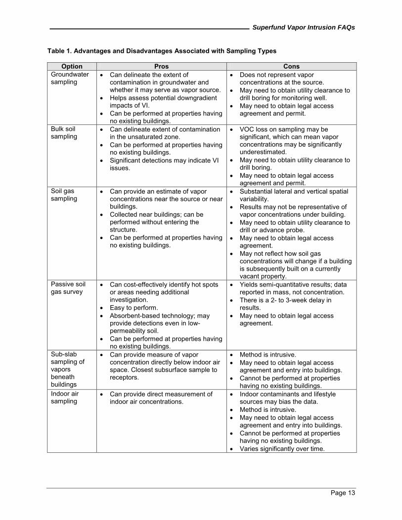
The number and types of samples used at a specific site should be decided by the VI site team based on the CSM and other site-specific information. The EPA recommends consulting with regional laboratory personnel to ensure the appropriate sampling and analytical methods are selected and that the laboratory detection limits are low enough to allow evaluation against the specific VI screening levels. Site teams should refer to the “Sampling and Analyses” section for additional information. The following table (Table 1) presents some of the key advantages and disadvantages associated with the various types of sampling (EPA 2008a). While some states do not recommend bulk soil sampling, available data may be considered if the state allows that type of data and appropriate SOPs are followed.
Superfund Vapor Intrusion FAQs
Page 13
Table 1. Advantages and Disadvantages Associated with Sampling Types
Option Pros Cons Groundwater sampling
Can delineate the extent of contamination in groundwater and whether it may serve as vapor source. Helps assess potential downgradient impacts of VI. Can be performed at properties having no existing buildings.
Does not represent vapor concentrations at the source. May need to obtain utility clearance to drill boring for monitoring well. May need to obtain legal access agreement and permit.
Bulk soil sampling
Can delineate extent of contamination in the unsaturated zone. Can be performed at properties having no existing buildings. Significant detections may indicate VI issues.
VOC loss on sampling may be significant, which can mean vapor concentrations may be significantly underestimated. May need to obtain utility clearance to drill boring.
May need to obtain legal access agreement and permit.
Soil gas sampling
Can provide an estimate of vapor concentrations near the source or near buildings. Collected near buildings; can be performed without entering the structure. Can be performed at properties having no existing buildings.
Substantial lateral and vertical spatial variability. Results may not be representative of vapor concentrations under building. May need to obtain utility clearance to drill or advance probe. May need to obtain legal access agreement.
May not reflect how soil gas concentrations will change if a building is subsequently built on a currently vacant property.
Passive soil gas survey
Can cost-effectively identify hot spots or areas needing additional investigation. Easy to perform.
Yields semi-quantitative results; data reported in mass, not concentration. There is a 2- to 3-week delay in results.
Absorbent-based technology; may provide detections even in low-permeability soil.
May need to obtain legal access agreement.
Can be performed at properties having no existing buildings.
Sub-slab sampling of vapors beneath buildings
Can provide measure of vapor concentration directly below indoor air space. Closest subsurface sample to receptors.
Method is intrusive. May need to obtain legal access agreement and entry into buildings. Cannot be performed at properties having no existing buildings.
Indoor air sampling
Can provide direct measurement of indoor air concentrations.
Indoor contaminants and lifestyle sources may bias the data.
Method is intrusive. May need to obtain legal access
agreement and entry into buildings. Cannot be performed at properties
having no existing buildings. Varies significantly over time.
Superfund Vapor Intrusion FAQs
Page 14
C.3 How many houses or buildings should be sampled? Which ones? The preferred approach generally is for the site team members to prepare a defensible investigative approach based on a site-specific conceptual model. At sites with a limited number of potentially affected buildings, it may be feasible to sample all of them. However, this approach may not be feasible at sites where a large number of buildings may be affected. If it is determined that sampling all buildings at a site is not practical, the site manager should consider whether the region is willing to support “preemptive mitigation.” "Pre-emptive mitigation" refers to the installation of mitigation system(s) in a building or set of buildings that have not been sampled to evaluate whether the vapor intrusion pathway is complete in those specific buildings, but where there is sufficient evidence from nearby buildings to warrant mitigation It is important to recognize at VI sites that the substantial spatial variability commonly observed in the concentrations of subsurface vapors (as result, for example, of heterogeneities in the subsurface materials and variations in source concentrations, among other factors) will often manifest in variability in indoor air concentrations. Additionally, building-specific characteristics and occupants’ activities that affect building ventilation will vary from building to building, further adding to the variability in indoor air concentrations. For these reasons, the EPA recommends that the site manager seek the advice of a hydrogeologist familiar with the site geology and consider as well as information about the building’s design, construction, condition and operations to help guide selection of sampling locations. In addition, it is important to recognize that not all property owners and renters will be willing to provide access for sampling. Naturally occurring radon may serve as a tracer to help identify those buildings that are more permeable to soil gas than others and, therefore, good candidates for VI sampling. While the underlying source strength of radon may vary across a site, the buildings with higher indoor air radon concentrations suggest they are more permeable to soil gases and would likely be more permeable to other subsurface gases. C.4 What is the duration of the vapor sampling event? The sampling duration depends on the type of medium being sampled (for example, soil gas, sub-slab soil gas and indoor or outdoor air) and analytical methods (for example, TO-15). Some of the key recommended considerations are provided below. The site team should specify sample durations in the sampling and analysis plan. Soil Gas Sampling Typically, grab samples are collected when soil gas exterior to buildings is sampled. The site team should allow some time after the sampler has been installed for the subsurface to return to equilibrium conditions because installing temporary or permanent soil gas probes can disturb subsurface conditions. The equilibrium time may depend on the type of drilling techniques used to install the soil gas probes, with more time needed for auger drilling compared with hand drilling. For example, the California Regional Water Quality Control Board (RWQCB) recommends an equilibration time of 20 to 30 minutes for temporary driven probes and 48 hours for probes installed using augered borings (California RWQCB 2003). Sub-slab Soil Gas Sampling An EPA study (EPA 2006) of equilibration rates (the time needed for the subsurface conditions to come back to equilibrium after they have been disturbed by installation of the soil gas probes) in sub-slab sampling found that the radius of perturbation (distance of disturbance created in the subsurface during installation of the soil gas probes) for sub-slab material consisting of silt or clay would be approximately 6 centimeters over an exposure period of 1 hour, thus requiring an equilibration time of approximately 10 hours. However, the study also found that, in most cases, an equilibration time of 2 hours should be sufficient before sampling because most sub-slab material consists of sand or a sand-gravel mixture — even for buildings built directly on clay (Section 5, EPA 2006). In addition, sub-slab sampling should be conducted at relatively the same time as indoor air sampling to allow for data comparison. The sub-slab sampling ports are installed after the indoor air sample is deployed and collected (8 to 24 hours later) to avoid biasing the indoor air concentrations with potentially higher sub-slab gas infiltration rates during
Superfund Vapor Intrusion FAQs
Page 15
installation. Alternatively, the sub-slab ports may be installed before indoor air sampling and sampled concurrently with the indoor air samples, provided sufficient time is allowed for the indoor air concentrations to return to “normal” after the sub-slab port has been installed. Results from sub-slab samples are typically similar whether they are collected over a short period of time (grab sample) or are collected over a longer period of time, such as a weighted average (8 to 24 hours sampling time). However, changes in weather conditions may cause short-term temporal variability in subsurface vapor concentrations, longer sample intervals may allow this variability to average out (for example, see Section D.8, ITRC 2007; McAlary and others 2002). Note that the sampling duration will depend on the analytical method used. Indoor Air Sampling Typically, indoor air samples are collected over a 24-hour period in residences or over an 8-hour period (workday equivalent) in commercial and industrial settings. One round of indoor air sampling may not be sufficient to understand indoor air contamination because of the uncertainty of indoor air dynamics. More samples typically will be appropriate at a site where the indoor air concentrations are only slightly above health-based concentrations. In addition, multiple sampling events may be necessary to account for seasonal variations in climate and changes in the habits of building occupants. Although indoor air sampling is preferable during the heating season because it may create a heating stack effect and present a worst-case in many areas, it may not be appropriate to delay sampling for several months. Another potential worst-case scenario may be when a building is sealed and the ventilation system is not operating. It is possible to compare indoor air and sub-slab soil gas contaminant concentrations if sub-slab samples are collected over the same period as the indoor air samples. The EPA generally does not recommend grab (instantaneous) samples for indoor air samples. Grab samples should be limited to locating contaminant sources and should not be used for risk information. The exception is when numerous gas samples are collected over an extended period, such as with the TAGA. Ambient (Outdoor) Air Sampling The EPA recommends beginning ambient air sampling at least 1 hour and preferably 2 hours before indoor air monitoring begins and continue sampling until at least 30 minutes before indoor monitoring is complete to measure ambient air concentrations. The EPA recommends this practice because most buildings have an hourly air exchange rate in the range of 0.25 to 1.0, causing air that enters the building before indoor air sampling to remain in the building for a long time (for example, see Section D.10, ITRC 2007). In addition, ambient air samples should be collected over the same sampling period as indoor air so contaminant concentrations can be compared between media. C.5 What are the contributors to temporal variability in the sampling results? There can be temporal and spatial variability in subsurface and indoor air concentrations. Temporal factors affecting subsurface measurements include seasonal changes in building depressurization caused by the use of fireplaces, heaters, open windows, and air conditioners, or wind; the movement of subsurface soil gas from barometric pumping caused by changes in both diurnal and longer-term atmospheric pressure; frozen ground; and temperature effects on contaminant partitioning. These factors should be considered in developing a sampling and analysis plan and evaluating the data. Because of temporal variability in sampling results, it is usually necessary to conduct several rounds of sampling to obtain representative measures of long-term exposure concentrations for risk assessment. C.6 How many rounds of sampling are needed to support a risk assessment or public health
evaluation for decision-making? There is no recommended number of sampling rounds, but more than one round is often needed to develop an understanding of temporal variability. The total number of sampling rounds generally should
Superfund Vapor Intrusion FAQs
Page 16
be based on the CSM and other site-specific information. The site team should ensure that the data are sufficient to characterize the potential exposure before decision-making. C.7 What are the units of measurement for air and soil gas samples? What is the conversion
factor from one unit to another? Unit conversion for air and soil gas generally is more complicated than for soil or water. Common units for soil gas are microgram per cubic meter (µg/m3), microgram per liter (µg/L), part per billion by volume (ppbv) and part per million by volume (ppmv). For risk assessment, future soil gas results should be requested in µg/m3 and for groundwater in µg/L. Table 2 below can be used to convert concentrations of existing data. Table 2. Soil Gas Unit Conversions (ITRC 2007)
Soil Gas Unit Comparison Units Convert to: Multiply By: g/L mg/m3 1 g/m3 mg/m3 0.001 ppbv g/m3 MW/24 g/m3 ppbv 24/MW ppmv mg/m3 MW/24 ppbv mg/m3 MW/24,000 g/L g/m3 1000 g/m3 g/L 0.001 g/L ppbv 24,000/MW g/L ppmv 24/MW ppbv ppmv 0.001 ppmv ppbv 1000
MW - molecular weight
3 mg/m - milligram per cubic meter 3
g/m - microgram per cubic meter
g/L - microgram per liter ppbv - part per billion by volume ppmv - part per million by volume
One source for molecular weights of contaminants is the “NIOSH Pocket Guide to Chemical Hazards" (www.cdc.gov/niosh/npg/). Another way to convert units is to use an on-line calculator. Here is one example that may be appropriate: www.epa.gov/athens/learn2model/part-two/onsite/ia_unit_conversion.html. C.8 How many indoor air samples should be obtained in a building? In general, site teams should collect one sample from a typical size residential building or a commercial building less than 1,500 square feet in the area directly above the foundation floor (basement or crawl space) and one from the first floor living or occupied area. Site teams should collect samples at the breathing zone level for the most sensitive receptor. In selecting the number of samples to collect, site teams should also consider internal building partitions; heating, ventilation, and air conditioning (HVAC) layout; contaminant distribution; utility conduits; and preferential pathways (for example, basement sumps or drains, relatively large holes or spaces in the foundation floor, or water-stained areas). However, rooms that are closed and connected to the outside at below-ground levels (floor drains, piping, and electrical) may have appreciable higher contaminant concentrations originating from VI and, therefore, may provide a higher exposure than rooms that are open on the ground level. Larger commercial and residential buildings may require additional discussion with the site team and a statistician to select the appropriate number and placement of indoor air samples.
Superfund Vapor Intrusion FAQs
Page 17
C.9 What information should be gathered prior to sampling indoor air in residential/commercial buildings?
The EPA recommends that the following information be gathered when a building is sampled. This information should also be included on a home or building survey form:
Building ventilation system. For commercial buildings, the zone of influence (each zone may need to be sampled); an HVAC or mechanical engineer can evaluate the ventilation inside the building based on the HVAC zones of influence. More ventilation typically results in lower contaminant concentrations in indoor air.
Air exchange rate for each building or ventilation system. (Subsurface screening levels assume an adequate but modest air exchange rate.)
Physical building properties, such as utility pits, elevators, basements, or crawl space.
Any non-ventilated or passively ventilated rooms (such as mechanical rooms where vapors may build up).
Hours of building occupancy (current and future conditions, as appropriate), particularly for the
commercial setting. This information should factor into the sampling period needed to represent exposure.
Potential pathways for subsurface migration into the building. (Sealing these pathways often can
be a cost-effective mitigation measure.)
Areas with significant positive or negative pressure. (Negative pressure inside buildings facilitates VI.)
Products used or stored within a building that can act as potential indoor air sources, particularly
process operations and chemicals of concern in a commercial/industrial setting.
Multiple exposure units or receptor populations within a building. Examples of building surveys can be found in the EPA’s 2002 guidance (Appendix I, EPA 2002), ITRC’s 2007 guidance (Appendix G, ITRC 2007), and NJDEP’s 2005 guidance (Appendix B, NJDEP 2005). C.10 Is it necessary to remove indoor sources before crawlspace, sub-slab, or indoor air
samples are collected? If you are sampling for sub-slab soil gas or indoor air, the EPA generally recommends removing potential indoor air sources (for example, household or consumer product chemicals, paints, gasoline, dry cleaned clothing, and nail polish) from the structure. It is generally recommended that potential indoor air sources be removed from the structure and stored in a secure location at least 24 to 72 hours before sampling begins based on an approximate air exchange rate of 0.25 to 1.0 per hour. Note that the effects of indoor sources may linger longer depending on source strength, relative humidity inside the building, and the extent to which the contaminants have been absorbed by carpets and other fabrics or “sinks.” In addition, depending on pressure differentials, it may be possible for indoor air to migrate into the subsurface, creating false positives in sub-slab soil gas samples. The EPA recommends conducting an indoor air survey in all buildings before sampling. This survey should document all sources of volatile chemicals present in the structure. Section 1.6.1 of ITRC’s 2007 guidance (ITRC 2007) may provide useful information on this issue. In some circumstances, a real-time part per billion (ppb) photoionization detector (PID) can be used to survey the house or building for VOC contributions to indoor air from indoor sources; however, the ppb PID may not be sensitive enough for
Superfund Vapor Intrusion FAQs
Page 18
very low-concentration sources. More sensitive options may include use of the HAPSITE GC/MS or the TAGA Mobile Laboratory. More information is available about the TAGA Mobile Laboratory at www.epa.gov/Region6/6lab/taga.htm. In some cases, contaminated groundwater may serve as a direct source of vapors if the contaminated groundwater is within the structure. For example, even when an alternative drinking water supply is being provided, contaminated groundwater may be used for other domestic purposes, such as bathing and showering, and act as an exposure pathway. Additionally, contaminated groundwater may be present in sumps where it can directly off gas into buildings. C.11 Should the site team collect ambient (outdoor) air samples? The site team usually should collect ambient air samples whenever indoor air samples are collected. Normally, one or two samples each day of sampling should be sufficient unless the site team is assessing multiple buildings over a wide area. Nearby buildings with air emissions from commercial or industrial facilities should be considered, and potential outdoor sources of pollutants should be noted on all home and building surveys. Collection of relevant meteorological data during the sampling event should also be considered. Additional information that may be useful about ambient air samples can be found in the ITRC 2007 and NJDEP 2005 VI guidance documents (ITRC 2007, NJDEP 2005). C.12 How many sub-slab samples are recommended per building? Field experience indicates there may be substantial spatial variability in concentrations even over an average-sized basement footprint. While recommendations vary as to how many sub-slab samples are appropriate — ranging from one sub-slab sample collected for every 330 square feet (or two to three samples collected for every average-sized home) to one sub-slab sample for an average residential dwelling of 1,500 square feet — the EPA recommends the samples be located near the center of the slab. Site teams should also consider internal building partitions, HVAC layout, contaminant distribution, utility conduits, and preferential pathways in selecting locations for collecting sub-slab samples. Although it may be desirable to collect several sub-slab samples from a building to gain an understanding of spatial variability, it may be impractical based on construction considerations (for example, utilities, floor condition or floor materials), cost, or the owner’s permission to install multiple sampling ports. However, multiple ports should be installed in a minimum percentage (more than 10 percent) of the buildings sampled to provide a check for variability in an area. Furthermore, based on work conducted in New York State up to the spring of 2010, it appears that the sub-slab concentrations beneath the central area of a home are usually (75 percent of the time) as high as or higher than the concentrations closer to the perimeter of the home. Consequently, to be practical (that is, more efficient and also less imposing on the homeowner), the New York Department of Environmental Conservation (NYDEC) has typically relied on single, central point sub-slab samples in residential VI sampling for the initial screen. If the indoor and sub-slab concentration ratios are out of line with expectations based on data from neighboring homes and nearby environmental data (usually groundwater), then multipoint sub-slab samples are considered to help resolve the uncertainty. Certain situations should trigger discussions about the number of sample locations per building: (1) where there are fewer surrounding buildings that are being sampled (that could have helped the understanding of typical sub-slab values and variability), (2) very large or small homes or buildings, (3) buildings with more than one foundation floor type, (4) subsurface structures or conditions that might facilitate or mitigate VI, (5) multi-use buildings with sensitive populations in segmented areas (day care, for example), and (6) areas of the building directly above the subsurface with constant occupancy as opposed to occasional occupancy. For larger structures, a statistician may help identify the number and placement of sampling ports to meet the desired DQOs. In limited cases, it may also be helpful to collect ambient (outdoor) air samples during sub-slab sampling events to ensure that the ambient air is not contributing to sub-slab conditions.
Superfund Vapor Intrusion FAQs
Page 19
C.13 Are there other special considerations when conducting sub-slab sampling? There are special considerations for sub-slab soil gas samples because of either unique construction practices (for example, pretension concrete slabs) or environmental situations. Section D6 of the ITRC’s 2007 guidance (ITRC 2007) lists some key considerations that may be useful, which include:
Sub-slab samples should be avoided in areas where groundwater might intersect the slab.
Underground utilities and structures (for example, electric, gas, water or sewer lines) should be located and avoided to prevent damage to the lines; however, samples should be collected in close proximity to these potential preferential vapor pathways.
If a vapor barrier already exists under the slab, sub-slab sampling is not recommended, as it
might puncture the barrier. If a site team decides to proceed with sub-slab sampling, it is important to perform leak testing to ensure the hole is properly sealed, for example, through the use of a helium tracer gas shroud.
The primary entry points for vapors in basements might be through the sidewalls rather than from
below the floor slab, so the site team might need to augment sub-slab samples with samples through the basement walls.
The site team may want to take advantage of existing cracks or other openings in the basement
floor or walls to minimize the need to drill through the floor slab. However, this approach poses additional challenges to minimize short-circuiting during sampling.
The location of cables in post-tensioned concrete should be identified (usually with ground-
penetrating radar) before sub-slab sampling, as drilling through a cable is a significant health and safety concern and may damage the slab (California Department of Toxic Substances Control [DTSC] 2011).
C.14 What type of sampling is appropriate when there is a partial basement or dirt floor in the
basement? A sampling port should be installed in basements with a partial slab large enough to allow vapors to accumulate (for example, if the slab covers more than 50 percent of the building footprint). One sub-slab port should be installed on the slab portion for basements with a partial slab and one indoor air sample should be collected directly over the dirt portion. If there is a dirt floor in a basement, indoor air in the basement or soil gas should be sampled to assess a subsurface source. In addition, a soil gas sample can be collected 3 to 5 feet below ground surface if conditions allow. C.15 What about sampling soil gas during or soon after significant rainfall? Moisture content typically changes over time, with climatic conditions controlling precipitation and evapotranspiration. Precipitation may cause the water table to rise and with it the contaminant source zone. This rising water table can result in a contaminated capillary fringe, which can increase the source vapor concentration above the capillary fringe. Fluctuations in the water table where NAPL is present can result in repeated trapping and exposing of NAPL to soil gas. Drought conditions may lower the water table and expose previously trapped NAPL product, greatly increasing the NAPL partitioning into soil gas. These and other conditions may affect soil gas concentrations and should be addressed to provide the site team with guidance regarding when sampling should occur to evaluate conservative, “worst-case” VI (EPA 2005a, Schumacher 2009). Soil gas measured under buildings during or immediately after a significant rain event (greater than 1 inch) may provide a “worst-case” scenario, as precipitation may displace soil gas and create an increase in VI near a building, which may not be representative of long-term average conditions. However,
Superfund Vapor Intrusion FAQs
Page 20
precipitation may also create a clean lens over the groundwater, which may be a longer-term condition that traps soil gas and minimizes VI farther away from a building. Additional information that may be relevant to the effects of weather events on sampling and sampling results is discussed in Section D.11.8 of ITRC’s 2007 VI guidance (ITRC 2007). Relevant meteorological data, such as high wind speed, snow cover, and changes in barometric pressure, should be collected in conjunction with other data collection events. C.16 How should soil gas samples be collected when access is denied for sub-slab sampling? Soil gas concentrations adjacent to buildings can exhibit considerable variability. For this reason, site teams should collect soil gas samples at multiple depths and multiple locations, as close to the building foundation as feasible, with a minimum of two samples collected at different depths (preferably one near the source) at each location. The site team should collect the shallow sample no less than 5 to 10 feet below ground surface, depending on site-specific conditions. The deeper sample should be collected just above the source of contamination, which is often the water table. C.17 Should additional sampling be considered if a building already has a radon mitigation
system installed and functioning? Generally, yes; sampling might include some performance measure of the existing radon system, such as measuring pressure differentials or mechanical testing to assess the capture zone. In addition, sampling to assess VI COC levels and removal efficiency may also be conducted. C.18 How is a site assessed for VI when no buildings are present? Multiple lines of evidence generally should be used to assess the potential for VI in future buildings. Typically, a survey of site history and site conditions, including soil characteristics and subsurface geology, is conducted. Then, information to support a multiple lines of evidence analysis (groundwater data, soil gas data and soil concentrations) should be collected. Another line of evidence that can be used is the Johnson and Ettinger (J&E) model to estimate future conditions using typical building parameters. After appropriate lines of evidence have been obtained, the site manager should then evaluate whether ICs may be needed to complement other response actions (for example, engineered response action components) to limit the potential for VI in future buildings. For future development, the VI assessment may need to be re-evaluated because of changes in site conditions, such as land use, source remediation, or plume migration. Additional information may also be found in the EPA’s Brownfields Technology Primer: Vapor Intrusion Considerations for Redevelopment, EPA 542-R-08-001, March 2008 (EPA 2008a). D. DATA EVALUATION D.1 How do I determine whether the VI pathway is complete? How do I determine whether
measured indoor air concentrations can be reasonably attributed to VI? Several methods of data evaluation may be considered, and site managers should evaluate a number of methods, including:
Compare indoor air concentrations with typical background values: If much greater than the typical range, there is a greater likelihood that the indoor air concentrations are the result of VI. The potential indoor sources should be identified and removed during a site reconnaissance and home or building survey to ensure that the concentrations measured in the indoor air samples are attributable to the VI pathway. Field experience suggests that it may not be possible to remove all sources. In evaluating the influence of background sources, site-specific values for background levels should be used when available; however, typical background values may be used when site data are limited or site conditions do not allow collection of representative background data. Additional information about background sources can be found in the EPA’s Background Indoor Air Concentrations of Volatile Organic Compounds in North American Residences (1990-2005):
Superfund Vapor Intrusion FAQs
Page 21
A Compilation of Statistics for Assessing Vapor Intrusion, EPA 30-R-10-001, June 2011 (www.epa.gov/oswer/vaporintrusion/documents/oswer-vapor-intrusion-background-Report-062411.pdf) (EPA 2011b). In commercial buildings, there is a potential for the HVAC system to contribute to indoor air concentrations, depending on the location of the vent and exhaust with regard to other sources. For example, HVAC intakes adjacent to or near dry cleaning facilities may introduce the dry cleaning solvent into the building.
Compare relative proportions of chemicals in indoor air with the relative proportions of chemicals
in subsurface media. Relative proportions in indoor air and subsurface vapor samples should be similar if VI is responsible for indoor air concentrations. If the main COCs are identified in similar proportions between the sub-slab, soil gas, and indoor air samples, the indoor air concentrations measured are most likely associated with the VI pathway. If a contaminant is detected in significant concentrations in the indoor air but is not present or barely present in the subsurface, then the presence of this contaminant in indoor air may not be associated with the VI pathway but rather with potential indoor sources.
Evaluate potential tracers of the VI pathway — for example, compounds that are rarely found in
household products, such as dichloroethene (DCE).
Note whether subsurface tracers unrelated to VOC contamination, such as naturally occurring radon, appear in indoor air. In a radon-free structure, tracers, such as sulfur hexafluoride and helium, can be injected in the subsurface at selected concentrations and the VI pathway is typically determined to be complete if indoor air samples then have detectable concentrations of the tracer.
Compare subsurface concentrations with screening levels; if much greater than screening levels,
there generally is a greater likelihood that VI is responsible.
Conduct sampling with the building pressurized and then again with the building depressurized. Recent research shows that this sampling approach can demonstrate whether indoor air contamination comes from the subsurface or elsewhere.
D.2 Are there updates to the screening tables in the 2002 draft VI guidance? Since the 2002 draft VI guidance was released, the Superfund program has issued guidance recommending consideration of the Agency’s inhalation dosimetry methodology (See Risk Assessment Guidance for Superfund [RAGS] Part F, www.epa.gov/oswer/riskassessment/ragsf/, EPA 2009a), which recommends against using simple route-to-route extrapolation, as was used in the 2002 draft VI guidance. Thus, the Agency recommends not using the screening tables in the 2002 draft VI guidance. An updated collection of inhalation toxicity values and associated ambient air screening levels can be found in the Regional Screening Levels (RSLs) for Chemical Contaminants at Superfund Sites (www.epa.gov/reg3hwmd/risk/human/rb-concentration_table/index.htm, EPA 2011d). There are some important potential considerations in using the toxicity values shown in the RSL tables as a source of toxicity values, including:
The RSLs are updated only every 6 months. Occasionally, new toxicity values may be available in the sources used by the RSLs, which are not yet presented in the RSL tables. In addition, some toxicity values shown in the RSL tables may no longer exist and will be dropped in the next 6-month update of the RSLs. (For specific questions on the status of select toxicity values in the RSL table, contact Michele Burgess at: [email protected] or 703-603-9003).
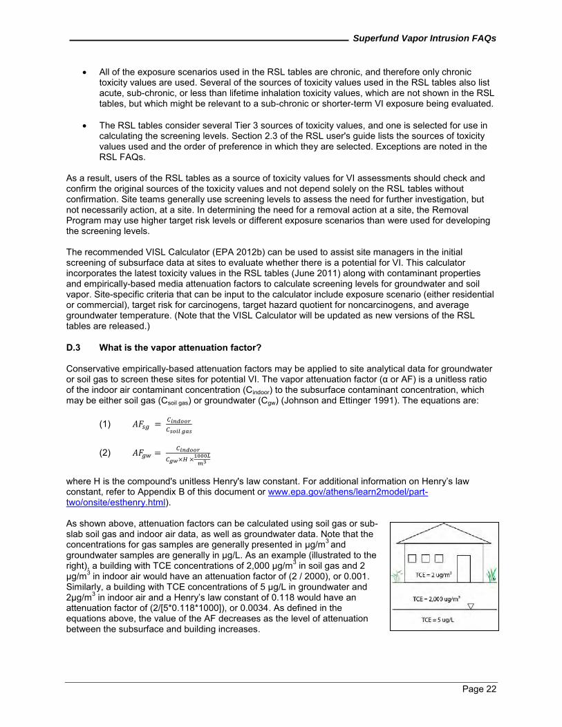
Superfund Vapor Intrusion FAQs
Page 22
All of the exposure scenarios used in the RSL tables are chronic, and therefore only chronic toxicity values are used. Several of the sources of toxicity values used in the RSL tables also list acute, sub-chronic, or less than lifetime inhalation toxicity values, which are not shown in the RSL tables, but which might be relevant to a sub-chronic or shorter-term VI exposure being evaluated.
The RSL tables consider several Tier 3 sources of toxicity values, and one is selected for use in
calculating the screening levels. Section 2.3 of the RSL user's guide lists the sources of toxicity values used and the order of preference in which they are selected. Exceptions are noted in the RSL FAQs.
As a result, users of the RSL tables as a source of toxicity values for VI assessments should check and confirm the original sources of the toxicity values and not depend solely on the RSL tables without confirmation. Site teams generally use screening levels to assess the need for further investigation, but not necessarily action, at a site. In determining the need for a removal action at a site, the Removal Program may use higher target risk levels or different exposure scenarios than were used for developing the screening levels. The recommended VISL Calculator (EPA 2012b) can be used to assist site managers in the initial screening of subsurface data at sites to evaluate whether there is a potential for VI. This calculator incorporates the latest toxicity values in the RSL tables (June 2011) along with contaminant properties and empirically-based media attenuation factors to calculate screening levels for groundwater and soil vapor. Site-specific criteria that can be input to the calculator include exposure scenario (either residential or commercial), target risk for carcinogens, target hazard quotient for noncarcinogens, and average groundwater temperature. (Note that the VISL Calculator will be updated as new versions of the RSL tables are released.) D.3 What is the vapor attenuation factor? Conservative empirically-based attenuation factors may be applied to site analytical data for groundwater or soil gas to screen these sites for potential VI. The vapor attenuation factor (α or AF) is a unitless ratio of the indoor air contaminant concentration (Cindoor) to the subsurface contaminant concentration, which may be either soil gas (Csoil gas) or groundwater (Cgw) (Johnson and Ettinger 1991). The equations are:
(1)
(2)
where H is the compound's unitless Henry's law constant. For additional information on Henry’s law constant, refer to Appendix B of this document or www.epa.gov/athens/learn2model/part-two/onsite/esthenry.html). As shown above, attenuation factors can be calculated using soil gas or sub-slab soil gas and indoor air data, as well as groundwater data. Note that the
3 concentrations for gas samples are generally presented in µg/m and groundwater samples are generally in µg/L. As an example (illustrated to the
3right), a building with TCE concentrations of 2,000 µg/m in soil gas and 2 3µg/m in indoor air would have an attenuation factor of (2 / 2000), or 0.001.
Similarly, a building with TCE concentrations of 5 µg/L in groundwater and 32µg/m in indoor air and a Henry’s law constant of 0.118 would have an
attenuation factor of (2/[5*0.118*1000]), or 0.0034. As defined in the equations above, the value of the AF decreases as the level of attenuation between the subsurface and building increases.
Superfund Vapor Intrusion FAQs
Page 23
D.4 What are OSWER's recommended conservative generic screening level attenuation factors?
The 2002 draft VI guidance recommended soil gas and groundwater screening levels (that is, “target concentrations”) based on generic conservative screening level attenuation factor values. The recommended screening level attenuation factors were intended to generally capture a reasonable worst-case setting. A preliminary evaluation of the paired environmental samples in EPA’s expanded VI Database (EPA 2008b) indicates that the 2002 recommended screening level attenuation factors generally remain appropriate, except for the deep soil gas factor.
Recommended Attenuation Factors: AFgw (groundwater to indoor air) = 0.001 AFsg (soil gas to indoor air) = 0.1* AFss (sub-slab to indoor air) = 0.1 AFcs (crawl space to indoor air) = 1
The 2002 generic attenuation factor for deep soil gas was not supported by the evaluation of the expanded database (EPA 2008b). As a result, the EPA recommends using the same attenuation factor for shallow and deep soil gas. In other words, an attenuation factor of 0.1 is recommended as the conservative screening-level attenuation factor for all soil gas samples, whether sub-slab vapor or exterior soil vapor. This recommended value is the approximate 95th percentile of the observed sub-slab attenuation factors in the National VI Database as of 2008 for the subset of data with indoor air concentrations above typical background levels (EPA 2011e); that is, approximately 95 percent of the observed and reported values were lower (have greater attenuation). These attenuation factors may be used to support risk management decisions. For example, if sub-slab concentrations are measured or reasonably estimated to be below 10 times the target indoor air concentrations, then VI generally will not be a concern for the subject buildings. If sub-slab concentrations are greater than one order of magnitude (10X) the target indoor air concentrations, then the buildings should generally be subjected to further investigation for possibly unacceptable exposure levels in indoor air. If the sub-slab concentrations are more than three orders of magnitude (1,000X) greater than the target indoor air concentrations, vapor intrusion is likely to lead to unacceptable indoor air concentrations and mitigation should be considered. The Removal Program, in evaluating the need for a removal action, may use different attenuation factors than those used for screening purposes by the Remedial Program. Also, regions or states may use their own attenuation factors, as appropriate. Attenuation factors derived from site-specific empirical data or validated site-specific J&E model simulations may also be used where appropriate instead of the generic screening level attenuation factors. Note that the EPA does not encourage the use of the J&E model as the sole line of evidence for screening out sites. Site-specific attenuation factors may be substantially greater (indicate more attenuation) than the default general attenuation factors, depending on site-specific conditions. D.5 Can modeling be used to assess the VI pathway? Mathematical modeling is just one tool that can be used to help assess the VI pathway (EPA 2002) and typically gives the best results when used with high-quality data inputs (that is, representative groundwater or soil gas concentrations, depth to groundwater, and soil type). The EPA does not recommend modeling as the only line of evidence to screen out a site. It is most appropriately used in conjunction with other lines of evidence. However, in certain situations, reliance on modeling might be the only option (for vacant or undeveloped properties). Note that state and local regulations may view modeling as either a preferred or unacceptable line of evidence.
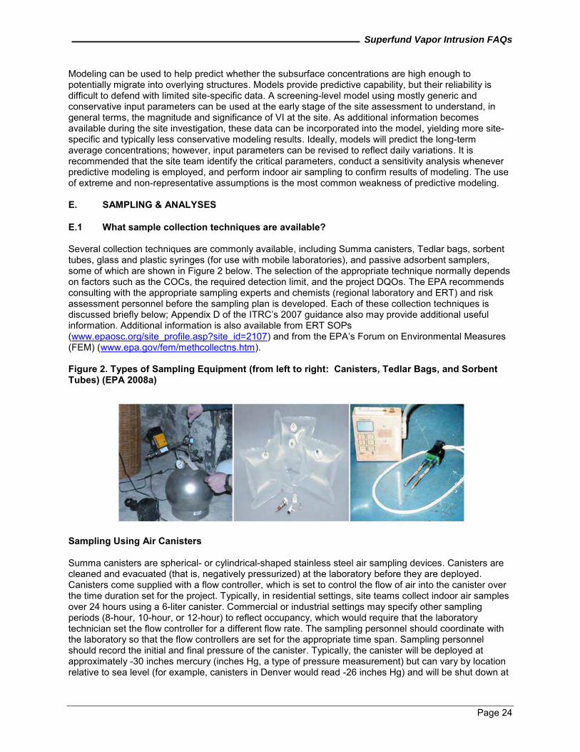
Superfund Vapor Intrusion FAQs
Page 24
Modeling can be used to help predict whether the subsurface concentrations are high enough to potentially migrate into overlying structures. Models provide predictive capability, but their reliability is difficult to defend with limited site-specific data. A screening-level model using mostly generic and conservative input parameters can be used at the early stage of the site assessment to understand, in general terms, the magnitude and significance of VI at the site. As additional information becomes available during the site investigation, these data can be incorporated into the model, yielding more site-specific and typically less conservative modeling results. Ideally, models will predict the long-term average concentrations; however, input parameters can be revised to reflect daily variations. It is recommended that the site team identify the critical parameters, conduct a sensitivity analysis whenever predictive modeling is employed, and perform indoor air sampling to confirm results of modeling. The use of extreme and non-representative assumptions is the most common weakness of predictive modeling. E. SAMPLING & ANALYSES E.1 What sample collection techniques are available? Several collection techniques are commonly available, including Summa canisters, Tedlar bags, sorbent tubes, glass and plastic syringes (for use with mobile laboratories), and passive adsorbent samplers, some of which are shown in Figure 2 below. The selection of the appropriate technique normally depends on factors such as the COCs, the required detection limit, and the project DQOs. The EPA recommends consulting with the appropriate sampling experts and chemists (regional laboratory and ERT) and risk assessment personnel before the sampling plan is developed. Each of these collection techniques is discussed briefly below; Appendix D of the ITRC’s 2007 guidance also may provide additional useful information. Additional information is also available from ERT SOPs (www.epaosc.org/site_profile.asp?site_id=2107) and from the EPA’s Forum on Environmental Measures (FEM) (www.epa.gov/fem/methcollectns.htm). Figure 2. Types of Sampling Equipment (from left to right: Canisters, Tedlar Bags, and Sorbent Tubes) (EPA 2008a)
Sampling Using Air Canisters Summa canisters are spherical- or cylindrical-shaped stainless steel air sampling devices. Canisters are cleaned and evacuated (that is, negatively pressurized) at the laboratory before they are deployed. Canisters come supplied with a flow controller, which is set to control the flow of air into the canister over the time duration set for the project. Typically, in residential settings, site teams collect indoor air samples over 24 hours using a 6-liter canister. Commercial or industrial settings may specify other sampling periods (8-hour, 10-hour, or 12-hour) to reflect occupancy, which would require that the laboratory technician set the flow controller for a different flow rate. The sampling personnel should coordinate with the laboratory so that the flow controllers are set for the appropriate time span. Sampling personnel should record the initial and final pressure of the canister. Typically, the canister will be deployed at approximately -30 inches mercury (inches Hg, a type of pressure measurement) but can vary by location relative to sea level (for example, canisters in Denver would read -26 inches Hg) and will be shut down at
Superfund Vapor Intrusion FAQs
Page 25
a slightly negative pressure (-2 to -4 inches Hg). The slight negative pressure ensures that the canister is filled over the entire planned sampling period; if the canister is at 0 inch Hg (that is, atmospheric pressure), the sampling personnel have no way of knowing if the canister filled over the planned duration or a shorter time period. Many site managers choose to request a specific targeted list of analytes based on site history or known contamination in groundwater, soil gas or sub-slab gas. Requesting an extensive list of analytes that are not site-related, but that may be present in indoor air from consumer products, may create the potential for confusion in risk communication. If the site history and subsurface data do not include benzene, for example, it may be appropriate for site managers to exclude benzene as a target analyte because of the possibility that benzene from a garaged car, lawnmower or snow blower may confound interpretation of the data. The target analyte lists should include degradation products. For example, for a PCE and TCE site, the site manager may choose a short list of analytes that includes PCE; TCE; cis-1,2- DCE; and vinyl chloride; since that list includes the usual primary COCs and their degradation products. Site teams should contact laboratory personnel for questions on specific compound recovery. Some semivolatile compounds are not amenable to soil vapor sampling directly. Adsorptive sampling methods are generally the preferred option at sites where there are COCs that are semivolatile, even though Summa canisters may be an acceptable technique for select semivolatile compounds (Fortune and others 2009). Note that the type of sampling method depends on the analytical method. Sampling Using Tedlar Bags Tedlar bags are sampling vessels constructed from polymeric materials and are effective for sampling for analysis of VOCs. However, the holding times for Tedlar bags are considerably more limited than for canisters because of surface and permeability issues. Some semivolatile compounds such as naphthalene may adhere to the surface of the Tedlar bag and yield a false negative result. In addition, Tedlar bags should be kept out of sunlight to minimize possible degradation of the sample. Tedlar bags may be preferable to canisters for certain compounds, and the associated costs are lower if analyzed at an on-site laboratory. Since Tedlar bags have limited holding times, these types of samples should be analyzed on site to reduce the period between sampling and analysis. If the sampling personnel transport the samples to an off-site laboratory, holding time should be considered to ensure that the samples are analyzed within the necessary timeframe. If samples are shipped by air, they need to be transported in an airtight container or with a reduced volume to avoid rupturing the Tedlar bags as a result of in-flight pressure changes. Samples containing compounds with high concentrations or low molecular weights with high vapor pressures may diffuse out of the Tedlar bags and into Tedlar bags that contain lower concentrations, resulting in samples with lower or higher concentrations than the initial concentrations. Laboratory technicians should bake and flush Tedlar bags with nitrogen before use to lower the concentrations of volatile compounds associated with the Tedlar bags themselves (that is, dimethyl acid amide and toluene). Sampling personnel should use Tedlar bags to collect grab samples and not time-weighted samples. Moreover, the sampling personnel should collect the sample using a vacuum box and not a peristaltic pump. Table 3 below presents some of the features of canisters and Tedlar bags in sampling for VOCs.
Superfund Vapor Intrusion FAQs
Page 26
Table 3. Comparison of Canisters and Tedlar Bags (Air Toxics 2011)
Canisters Tedlar Bags
Common Volumes 1 and 6 L 1, 3, and 5 L Type of Sampling Passive (vacuum) Active (pump required) Sample Handling Room temperature Room temperature Hold Time to Analysis Up to 30 days Up to 3 days Surface Inertness Excellent Fair Cleanliness 10 or 100% certified to ppbv/pptv levels Some VOCs present at 0.5 to 45
ppbv Sampling Application Ambient/indoor air, soil/landfill
stationary source gas, Ambient air (fixed gases only),
soil/landfill gas, stationary source Rule of Thumb “ppbv device” “ppmv device” Advantages Inertness, hold time, ruggedness, no
pump Purchase/shipping cost, availability, convenience
Sampling Using Adsorption Tubes Sampling tubes are cylinders packed with adsorptive material that may be used in an active or passive mode. In an active mode, air is drawn through the tubes, and the target compounds are adsorbed onto the enclosed matrix material. Adsorptive material is selected based on the material to be adsorbed and retained until released for analysis (that is, thermal desorption or solvent extraction). Proper selection of sorbent material for sample collection is important. Sampling personnel collect samples at a designated volumetric flow rate for a prescribed period. Sample collection at flow rates faster than the tube rating may result in erroneous results. Similarly, drawing samples for too short of a sampling period may result in insufficient target compounds to analyze by the prescribed method, while too long of a sampling period may result in breakthrough in the sampling medium by the target compounds. E.2 When sampling, what factors should be considered? The site team should evaluate a number of factors before performing any sampling, including:
1. What are the DQOs? In general, the site team should clearly state the DQOs by identifying the COCs, the specific decisions to be made based on the data collected, the anticipated risk-based levels, and the corresponding necessary detection limits. The DQOs generally help ensure the selection of the appropriate sampling device (for example, Summa canisters or Tedlar bags) and associated analytical method (such as TO-15) to ensure the samples can meet the appropriate detection limits. The site team should consult a chemist about DQOs and a risk assessor about collecting samples to be used in the risk assessment.
2. What are the appropriate sampling devices and analytical methods to help ensure that the device will properly collect and release the COCs for analysis using an instrumental technique that is qualitatively and quantitatively capable of achieving the quantification limits deemed appropriate for the investigation’s DQOs?
3. What is the sampling duration that should be representative of the conditions associated with anticipated exposures (for example, residential or industrial) and account for temporal changes in concentrations throughout the time period of sampling?
4. Will sampling activities introduce background contaminants into samples? These activities, including use of permanent markers and similar pens, wearing recently dry-cleaned clothing, smoking, and gassing up vehicles shortly before or during sampling, may affect the samples and should be avoided.
Superfund Vapor Intrusion FAQs
Page 27
5. Can sampling be performed in such a way as to minimize impact on the homeowners or renters? During sampling events, efforts should be made to minimize noise, impact to children and pets, and damage to hardscape, landscape, and floors.
E.3 Can mobile laboratory data be used for VI investigations? What about a field-portable gas
chromatograph/mass spectrometer (GC/MS)? A properly equipped mobile laboratory has the ability to perform fixed laboratory analysis in the field. Mobile laboratory data normally can be used to conduct potentially faster, cheaper VI investigations; however, the results may be more operator-dependent than those obtained from a fixed laboratory. The site manager should select a field GC/MS and mobile laboratory to meet the DQOs identified in the quality assurance project plan (QAPP). The mobile laboratory should have accreditation for the analytical method if the data will be used in risk assessment. As detection limits may vary for different analytes and different instrumentation, the mobile laboratory should provide documentation that its instruments can be calibrated at levels at or below the reporting limits required to meet the investigation’s DQOs. It may be difficult to achieve ultra-low detection limits (below 500 parts per trillion by volume [pptv]) in a mobile laboratory, because the lowest detection limits generally can be achieved only with a cryo-concentration with liquid nitrogen, and most mobile laboratories do not carry liquid nitrogen. If the site team has determined that ultra-low detection limits are required, the samples should be collected in canisters and transported to a fixed laboratory for analysis. The mobile laboratory may use EPA Method 8021B Modified or EPA Method 8260 Modified. These methods, which were originally written for analysis of water and soil, were modified for soil gas analysis. The data may be biased high (or low) relative to an air-specific method such as TO-14A, TO-15, or TO-17. The EPA recommends that at least 10 percent of the mobile laboratory samples be confirmed by analysis at a fixed laboratory by EPA Method TO-14A or TO-15. Methods 8021 and TO-14A cover a more restricted range of volatile organics, but they include a variety of possible detectors, which can offer better sensitivity. In contrast, the pure mass spectroscopy (MS) detector methods, such as TO-15 and 8260, cover a broader range but generally offer lower sensitivity. If the site manager is working with a limited number of contaminants, better sensitivity by MS methods may be achieved by using the selected ion monitoring (SIM) variant of MS. Because SIM is more prone to false positives, it is important that all contaminants to be measured by SIM MS methods are known to be present at the site based on previous investigations using full-scan MS methods. Alternatively, sample results obtained with the SIM method can be confirmed by reanalyzing the same samples by a full-scan method. Appendix C includes a summary of analytical methods that may be appropriate for VI sampling and analysis. Additionally, a field-portable GC/MS is a useful tool for VI investigations. Site teams may use a field GC/MS to identify pathways, such as gaps around utility conduits, transmissive slab cracks, or the migration of VOCs through electrical outlets. Field analytical capabilities continue to improve, along with innovations in electronics and GC column phases. E.4 Should tracer gas be used to test for leakage when sub-slab sampling is conducted? Tracer gas can be used to assess the integrity of the sampling equipment. If temporary probes are used, the EPA recommends tracer gas. The site team should consult experienced personnel before the sampling procedures are set up to evaluate the need for tracer gas. The site team may want to refer to analytical SOPs (EPA TO-14, TO-15, and TO-17) to assist in the selection of a tracer gas and establish the detection limits for the tracer gas that would ensure reliable leak testing results. Even with permanent probes, the EPA recommends a leak test to verify an adequate seal for each sampling event. Leak testing is most important at sites with shallow sample intervals (such as sub-slab) or large sample volumes (for example, see Hartman 2002). In some commercial/industrial sites, it may be appropriate to conduct a leak test before each sampling event, as the top of the permanent soil gas sampling points may have been damaged or affected by daily operations at the site, and a repair of the seal may be needed.
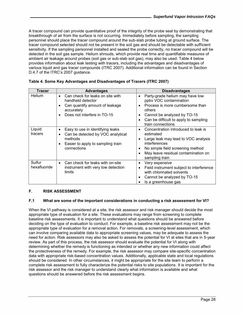
Superfund Vapor Intrusion FAQs
Page 28
A tracer compound can provide quantitative proof of the integrity of the probe seal by demonstrating that breakthrough of air from the surface is not occurring. Immediately before sampling, the sampling personnel should place the tracer compound around the sub-slab probe tubing at ground surface. The tracer compound selected should not be present in the soil gas and should be detectable with sufficient sensitivity. If the sampling personnel installed and sealed the probe correctly, no tracer compound will be detected in the soil gas sample. Helium shrouds, which provide real time and quantifiable measures of ambient air leakage around probes (soil gas or sub-slab soil gas), may also be used. Table 4 below provides information about leak testing with tracers, including the advantages and disadvantages of various liquid and gas tracer compounds (ITRC 2007). Additional information can be found in Section D.4.7 of the ITRC’s 2007 guidance. Table 4. Some Key Advantages and Disadvantages of Tracers (ITRC 2007)
Tracer Advantages Disadvantages Helium Can check for leaks on site with
handheld detector Can quantify amount of leakage
accurately Does not interfere in TO-15
Party-grade helium may have low ppbv VOC contamination
Process is more cumbersome than others
Cannot be analyzed by TO-15 Can be difficult to apply to sampling
train connections Liquid tracers
Easy to use in identifying leaks Can be detected by VOC analytical
methods Easier to apply to sampling train
connections
Concentration introduced to leak is estimated
Large leak may lead to VOC analysis interferences
No simple field screening method May leave residual contamination on
sampling train Sulfur hexafluoride
Can check for leaks with on-site instrument with very low detection limits
Very expensive Field instrument subject to interference
with chlorinated solvents Cannot be analyzed by TO-15 Is a greenhouse gas
F. RISK ASSESSMENT F.1 What are some of the important considerations in conducting a risk assessment for VI? When the VI pathway is considered at a site, the risk assessor and risk manager should decide the most appropriate type of evaluation for a site. These evaluations may range from screening to complete baseline risk assessments. It is important to understand what questions should be answered before deciding on the type of evaluation to conduct. For example, a baseline risk assessment may not be the appropriate type of evaluation for a removal action. For removals, a screening-level assessment, which can involve comparing available data to appropriate screening values, may be adequate to assess the need for action. Risk assessors may also be asked to assess the potential for VI at sites that are in 5-year review. As part of this process, the risk assessor should evaluate the potential for VI along with determining whether the remedy is functioning as intended or whether any new information could affect the protectiveness of the remedy. For example, the risk assessor may compare site-specific concentration data with appropriate risk-based concentration values. Additionally, applicable state and local regulations should be considered. In other circumstances, it might be appropriate for the site team to perform a complete risk assessment to fully characterize the potential risks to site populations. It is important for the risk assessor and the risk manager to understand clearly what information is available and what questions should be answered before the risk assessment begins.
Superfund Vapor Intrusion FAQs
Page 29
Some of the important considerations for evaluating VI are associated with each step in the risk assessment process and normally include the toxicity assessment, the exposure assessment, and the risk characterization. Much of the guidance and information used to conduct a human health risk assessment of a Superfund site are identified on the EPA’s Superfund Risk Assessment website (www.epa.gov/oswer/riskassessment/risk_superfund.htm). When health risk assessments are planned for building occupants subject to inhalation exposures through VI, the site team should, in particular, consult Part F of the Risk Assessment Guidance for Superfund (RAGS) (EPA 2009a), which provides recommended approaches for developing the information for each of these steps. These recommended steps are summarized below to provide a general introduction. The toxicity assessment generally consists of two related components: hazard identification and dose-response assessment. For the toxicity assessment, risk assessors should focus on those volatile chemicals that the site team identified as site-related through environmental sampling, which have physical characteristics to form vapors and where available toxicity values (that is, inhalation unit risk [IUR] or reference concentrations [RfC]) indicate that these vapors could result in adverse health effects. The recommended source for toxicity information is the EPA’s Integrated Risk Information System (IRIS), www.epa.gov/iris. For toxicity values obtained from the EPA’s IRIS database, acute exposures generally are defined as lasting 24 hours or less; sub-chronic exposures generally are defined as repeated exposures for more than 30 days and up to approximately 10 percent of the human lifespan; and chronic exposures generally are defined as repeated exposures for more than approximately 10 percent of the human lifespan (EPA 2009a). Another good source for these values can be the RSLs for Chemical Contaminants at Superfund Sites (EPA 2011d), which reflects the hierarchy for human health toxicity values for Superfund (OSWER Directive 9285.7-53). These tables are updated semi-annually. Regions should check to make sure the current values are being used. To the extent possible, the exposure duration (ED) represented by the toxicity value should be consistent with the ED evaluated in the exposure assessment. Exposure assessment generally is the determination or estimation of the magnitude, frequency, duration and route of exposure, which is defined as the contact of an organism (humans in the case of human health risk assessment) with a chemical or physical agent (EPA 1989). The amount of exposure is calculated for each exposure pathway and generally established by measuring or estimating the amount of contaminant that persons may contact during a specified time period (that is, ED). Exposure concentrations should be time-weighted average values based on the characteristics (for example, ED) of the exposure scenario being evaluated (EPA 2009a) and generally are estimated using direct measurement of indoor air concentrations, obtained in accordance with the EPA quality policies (for more information, visit www.epa.gov/QUALITY/qa_docs.html, EPA 2011c) (EPA 2002). Typically, risk assessors should develop exposure assessment plans in consultation with the site manager and in accordance with the CSM for VI to ensure that buildings with the greatest potential for VI are included in the assessment. Buildings of potential interest for VI are not limited to those directly above the contaminated area because of potentially complex vapor migration processes, particularly where preferential pathways for vapor transport, such as nearby atypical underground utilities or buried streambeds, are present. Site teams should also develop plans for conducting an exposure assessment in accordance with Part F of the RAGS (EPA 2009a) and Tier 3 of the draft 2002 VI guidance (EPA 2002). Risk characterization generally is the final, summarizing step in conducting a risk assessment. Generally, the purpose of the risk characterization section of a report is to describe the key findings and overall conclusions of the risk assessment in a transparent manner; identify and describe the scientific and policy assumptions used in the assessment; and characterize uncertainties in results. The EPA also recommends that the risk characterization explain any particular susceptibilities to inhaled toxicants or potential for increased inhalation exposures among the various receptor groups (for example, children or sensitive populations, such as the elderly or people with respiratory or pulmonary disease) at a site. When predicted cancer risks from multiple contaminants will be evaluated, risk assessors should estimate the cancer risk for each substance and then sum these risks (EPA 1989, Section 8.2.2). This approach should yield an estimate of total cancer risk, which represents the cumulative predicted cancer risk for the
Superfund Vapor Intrusion FAQs
Page 30
chemicals at a site. When multiple chemicals will be evaluated for cumulative noncancer effects by a common mechanism of toxicity, risk assessors typically first calculate an HQ for each substance, and then sum the individual HQ values to estimate a hazard index (HI) (EPA 1989, Section 8.2.2). Separate HIs should be calculated for each type of exposure period (that is, chronic, sub-chronic, and acute). The excess cancer risk and noncancer HQ values for individual chemicals should be calculated using the equations specified in Part F of the RAGS (EPA 2009a). In assessing the VI pathway, the site team should consider other site information (such as other lines of evidence) in addition to the indoor air concentration data typically collected at a site. This other information may include, but is not limited to, the geospatial distribution of sub-slab or deep soil gas across an investigation area, the presence of preferential pathways, and the status of remediation of the sources of the vapors. Consideration should also be given for early actions and how they may affect risk characterization. F.2 Should the site manager be concerned about differences in exposure and sampling
duration? Risk assessors should complete risk calculations using exposure concentrations that are representative of the exposure scenario being evaluated, which generally are based on sampling results. Risk assessors normally identify the representative exposure durations and frequencies. For example, human health risk assessments typically assess chronic exposure over several years. Sampling protocols, however, may lead site teams to collect samples over a 24-hour period, which would be representative of varying concentrations to which a receptor might be exposed over the course of 1 day. A single 24-hour sample may not be sufficient to develop a chronic exposure estimate because there can be seasonal variability in indoor air concentrations. Generally, aggregated 24-hour samples that represent the site conditions are preferred. Under certain circumstances, site teams may collect grab samples over a much shorter period, such as 15 minutes, to evaluate quickly whether vapors are collecting beneath a foundation. With these types of samples, there can be substantial temporal variability in concentration. For more details about sampling durations, refer to Question C.4, What is the duration of the vapor sampling event? While such sampling results may be employed as short-term exposure concentrations, they generally are not directly comparable to chronic or sub-chronic exposure values. The risk assessor and the risk manager should carefully evaluate the uncertainties associated with using these concentrations to characterize exposure amounts. Human health risk assessments typically use an upper-end estimate of exposure (and sometimes a central tendency estimate as well) to estimate exposure over extended periods (typically 30 years). For cancer risk, risk assessors generally average the estimated ED over 70 years (a default estimate for an average life expectancy). Exposure concentrations based on multiple samples are generally preferred because they better account for site variation (for example, seasonality). Sometimes, however, evaluations for VI are performed using only one data point; a single indoor air sample is not uncommon, for example, and the risk assessor may need to use this single point to evaluate the potential risks associated with exposure to that concentration. In these cases, the risk assessor should allow for the potential variability in the sampling results. F.3 What is the current approach for assessing sites that contain TCE? TCE is one of the most commonly encountered contaminants at Superfund sites. A revised TCE assessment was published in September 2011, which states that TCE is carcinogenic to humans. Additional information is available on the EPA's IRIS website at www.epa.gov/iris/subst/0199.htm. Note: It is important that the risk assessor and risk manager consider both the cancer and noncancer endpoints in evaluating the risk and whether it is appropriate to take action at a site.
Superfund Vapor Intrusion FAQs
Page 31
F.4 How should risk assessors evaluate chemicals for which no inhalation toxicity values (for example, RfCs and IURs) are available?
When indoor air or data from other media sampled are evaluated as part of a VI investigation, risk assessors should quantitatively evaluate the risk for those chemicals that have been assigned inhalation toxicity values, as identified in EPA’s Toxicity Hierarchy memorandum (www.epa.gov/oswer/riskassessment/pdf/hhmemo.pdf). The EPA no longer recommends using the simple 70-20 route-to-route method from RAGS, Part B, or the 2002 VI guidance (EPA 1991, EPA 2002) for VI assessments where no inhalation toxicity values (RfC or IUR) exist for contaminants of concern because of possible misrepresentations of risk that result from pharmacokinetic differences between routes (EPA 1998). The recommended approach is to either request (1) the Superfund Health Risk Technical Support Center (STSC) to develop a site-specific inhalation toxicity value, or (2) the risk assessor to conduct a qualitative exposure route evaluation and identify the uncertainty in the risk assessment. F.5 Should risks be calculated for adults and children separately? If adults and children are exposed under similar scenarios (that is, the exposure time, frequency, and duration are consistent), then no adjustment is normally necessary for the exposure. However, as activity patterns for children may differ, risk assessors should adjust the exposure scenario for children appropriately. If site-related chemicals that are known to act through a mutagenic mode of action (MMOA) for carcinogenicity are being evaluated, and no child-specific IUR exists, then it is generally appropriate to apply the age-dependent adjustment factors to the appropriate age ranges for children. The EPA does not recommend other adjustments to inhalation toxicity values when risk to children will be assessed. The list of chemicals that the EPA has identified as acting through an MMOA can be found at the following website: www.epa.gov/oswer/riskassessment/sghandbook/chemicals.htm (EPA 2011a). F.6 Is it appropriate to use Occupational Safety and Health Administration (OSHA) standards
in the Superfund program to evaluate worker risk associated with VI? OSHA and the EPA have agreed that OSHA generally will take the lead role in addressing occupational exposures. Workers will generally depend on the workplace (for example, OSHA) regulations (and medical monitoring, as needed) that already apply and are in place for their protection (for example, a health and safety plan). Risk assessors generally should not use the OSHA standards to evaluate risk from VI in the case where VI has been identified (for example, using multiple lines of evidence) in commercial/industrial settings where the COCs for the VI pathway are not used in the work place. Instead, site teams establish cleanup levels by ARARs or the risk assessment process at sites subject to CERCLA. OSHA standards generally are not risk-based and are not considered as ARARs under the CERCLA statute and regulations. F.7 What is the EPA’s position when VI is a potential concern in a non-residential setting? In all non-residential settings, the site team generally should take appropriate steps to (1) investigate VI exposures (for example, Regions may undertake a subsurface investigation to delineate the areal extent of a subsurface vapor plume), and (2) evaluate and, if needed, address vapor intrusion in non-residential environments even where there are workplace exposures to similar volatile chemicals (for example, reduce risks to acceptable levels with appropriate mitigation systems). In these non-residential settings, it is generally recommended that site teams evaluate VI risks using existing guidance with appropriate adjustments for non-residential building and exposure parameters. For example, decisions about indoor air sampling and building mitigation may depend on building-specific factors, such as HVAC system and occupational ‘background’ levels (such as indoor air concentrations that arise from indoor sources, including use and storage of vapor-forming substances).
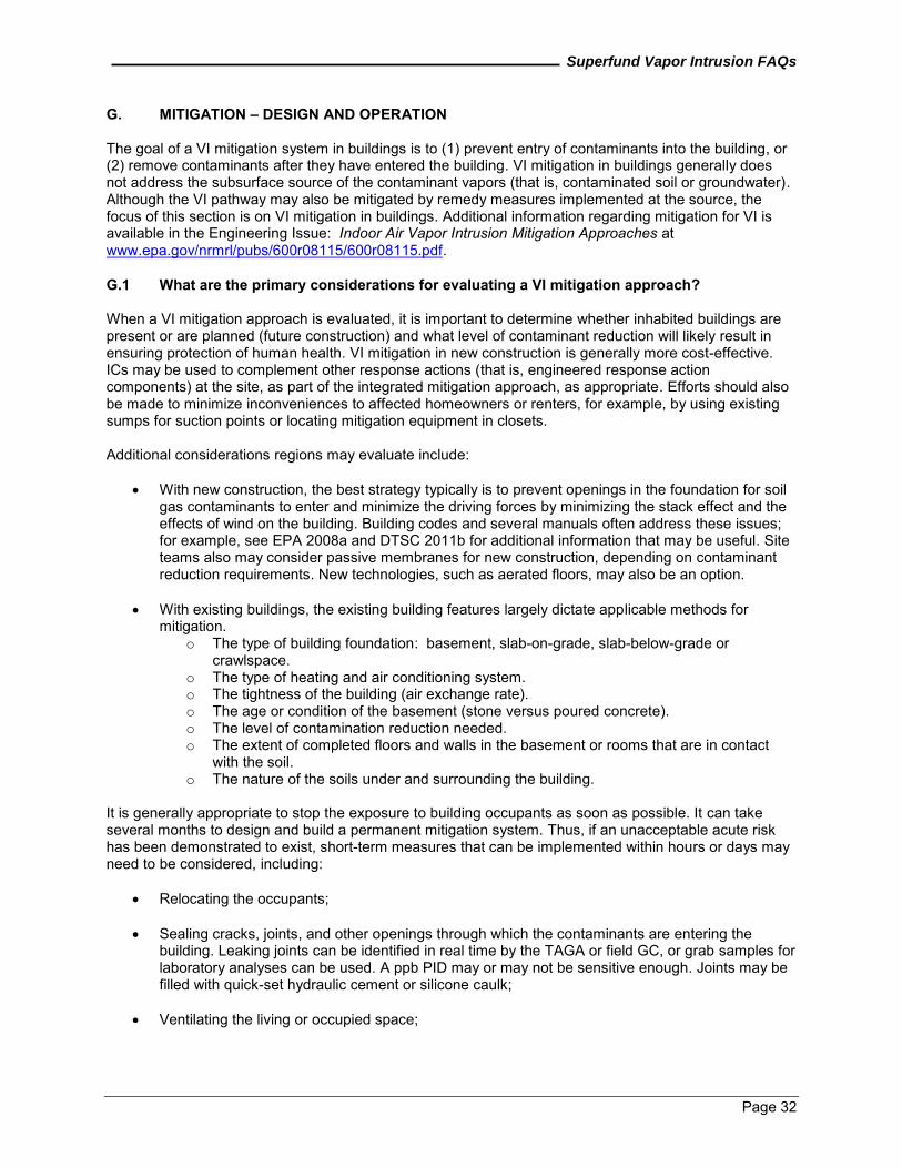
Superfund Vapor Intrusion FAQs
Page 32
G. MITIGATION – DESIGN AND OPERATION The goal of a VI mitigation system in buildings is to (1) prevent entry of contaminants into the building, or (2) remove contaminants after they have entered the building. VI mitigation in buildings generally does not address the subsurface source of the contaminant vapors (that is, contaminated soil or groundwater). Although the VI pathway may also be mitigated by remedy measures implemented at the source, the focus of this section is on VI mitigation in buildings. Additional information regarding mitigation for VI is available in the Engineering Issue: Indoor Air Vapor Intrusion Mitigation Approaches at www.epa.gov/nrmrl/pubs/600r08115/600r08115.pdf. G.1 What are the primary considerations for evaluating a VI mitigation approach? When a VI mitigation approach is evaluated, it is important to determine whether inhabited buildings are present or are planned (future construction) and what level of contaminant reduction will likely result in ensuring protection of human health. VI mitigation in new construction is generally more cost-effective. ICs may be used to complement other response actions (that is, engineered response action components) at the site, as part of the integrated mitigation approach, as appropriate. Efforts should also be made to minimize inconveniences to affected homeowners or renters, for example, by using existing sumps for suction points or locating mitigation equipment in closets. Additional considerations regions may evaluate include:
With new construction, the best strategy typically is to prevent openings in the foundation for soil gas contaminants to enter and minimize the driving forces by minimizing the stack effect and the effects of wind on the building. Building codes and several manuals often address these issues; for example, see EPA 2008a and DTSC 2011b for additional information that may be useful. Site teams also may consider passive membranes for new construction, depending on contaminant reduction requirements. New technologies, such as aerated floors, may also be an option.
With existing buildings, the existing building features largely dictate applicable methods for
mitigation. o The type of building foundation: basement, slab-on-grade, slab-below-grade or
crawlspace. o The type of heating and air conditioning system. o The tightness of the building (air exchange rate). o The age or condition of the basement (stone versus poured concrete). o The level of contamination reduction needed. o The extent of completed floors and walls in the basement or rooms that are in contact
with the soil. o The nature of the soils under and surrounding the building.
It is generally appropriate to stop the exposure to building occupants as soon as possible. It can take several months to design and build a permanent mitigation system. Thus, if an unacceptable acute risk has been demonstrated to exist, short-term measures that can be implemented within hours or days may need to be considered, including:
Relocating the occupants;
Sealing cracks, joints, and other openings through which the contaminants are entering the building. Leaking joints can be identified in real time by the TAGA or field GC, or grab samples for laboratory analyses can be used. A ppb PID may or may not be sensitive enough. Joints may be filled with quick-set hydraulic cement or silicone caulk;
Ventilating the living or occupied space;
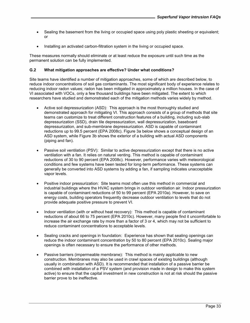
Superfund Vapor Intrusion FAQs
Page 33
Sealing the basement from the living or occupied space using poly plastic sheeting or equivalent; or
Installing an activated carbon-filtration system in the living or occupied space.
These measures normally should eliminate or at least reduce the exposure until such time as the permanent solution can be fully implemented. G.2 What mitigation approaches are effective? Under what conditions? Site teams have identified a number of mitigation approaches, some of which are described below, to reduce indoor concentrations of soil gas contaminants. The most significant body of experience relates to reducing indoor radon values; radon has been mitigated in approximately a million houses. In the case of VI associated with VOCs, only a few thousand buildings have been mitigated. The extent to which researchers have studied and demonstrated each of the mitigation methods varies widely by method.
Active soil depressurization (ASD): This approach is the most thoroughly studied and demonstrated approach for mitigating VI. This approach consists of a group of methods that site teams can customize to treat different construction features of a building, including sub-slab depressurization (SSD), drain tile depressurization, wall depressurization, baseboard depressurization, and sub-membrane depressurization. ASD is capable of contaminant reductions up to 99.5 percent (EPA 2008c). Figure 3a below shows a conceptual design of an ASD system, while Figure 3b shows the exterior of a building with actual ASD components (piping and fan).
Passive soil ventilation (PSV): Similar to active depressurization except that there is no active
ventilation with a fan. It relies on natural venting. This method is capable of contaminant reductions of 30 to 90 percent (EPA 2008c). However, performance varies with meteorological conditions and few systems have been tested for long-term performance. These systems can generally be converted into ASD systems by adding a fan, if sampling indicates unacceptable vapor levels.
Positive indoor pressurization: Site teams most often use this method in commercial and
industrial buildings where the HVAC system brings in outdoor ventilation air. Indoor pressurization is capable of contaminant reductions of 50 to 99 percent (EPA 2010a). However, to save on energy costs, building operators frequently decrease outdoor ventilation to levels that do not provide adequate positive pressure to prevent VI.
Indoor ventilation (with or without heat recovery): This method is capable of contaminant
reductions of about 66 to 75 percent (EPA 2010c). However, many people find it uncomfortable to increase the air exchange rate by more than a factor of 3 or 4, which may not be sufficient to reduce contaminant concentrations to acceptable levels.
Sealing cracks and openings in foundation: Experience has shown that sealing openings can
reduce the indoor contaminant concentration by 50 to 80 percent (EPA 2010c). Sealing major openings is often necessary to ensure the performance of other methods.
Passive barriers (impermeable membrane): This method is mainly applicable to new construction. Membranes may also be used in crawl spaces of existing buildings (although usually in combination with ASD). It is recommended that installation of a passive barrier be combined with installation of a PSV system (and provision made in design to make this system active) to ensure that the capital investment in new construction is not at risk should the passive barrier prove to be ineffective.
Superfund Vapor Intrusion FAQs
Page 34
Figure 3a. Conceptual Vapor Intrusion Mitigation System (EPA 2008a)
Figure 3b. Actual Vapor Intrusion Mitigation System (ITRC 2007)
Superfund Vapor Intrusion FAQs
Page 35
G.3 What is the difference between a construction vapor barrier and a VI barrier? Construction vapor barriers normally are thin plastic sheeting that is laid down below the concrete slab (prior to construction) to serve as a barrier to water vapor. Thus, construction vapor barriers usually are not considered robust enough to serve as VI barriers. Although they may provide minimal protection, they are frequently ripped during construction and penetrated by utility conduits (water, sewer, and electrical) that are not properly sealed. Manufacturers have designed VI barriers that typically are thicker than construction vapor barriers and additionally seek to prevent VI by sealing all penetrations. VI sheet barriers are typically 40 to 60 mil of high-density polyethylene (HDPE) or 30 mil of very low-density polyethylene (VDPE) (EPA 2008c). The use of thicker sheet barriers (60 to 100 mil) or ¼-inch layers of spray-on rubberized asphalt emulsions may reduce the potential for puncture or damage during installation (for example, see ITRC 2007 for additional information that may be useful). Site teams should test and inspect the integrity of seals along edges and at penetrations during and after construction to ensure proper installation (EPA 2008c). There are only a few studies in the literature that have reported on VOC contaminant reductions obtained through the use of a passive barrier; these studies have shown indoor VOC contaminant concentrations may be reduced to low ppb levels using a passive membrane. However, Synnott and others (2004) and Denman and others (2005) point out that as many as 50 percent of radon-proof membranes installed in new buildings may be ineffective. G.4 What diagnostic measurements should be used to select and design a mitigation system? An important diagnostic for an existing building typically is a visual survey to observe any outstanding construction features that will likely influence the selection or design of a mitigation system. In a visual survey, site teams generally should:
Observe whether there are basements, slabs-on-grade and crawlspaces. Check if these sections interact and if they require separate mitigation systems.
Observe major openings that must be closed for any system to function effectively.
Determine if there are sumps that must be sealed or given special treatment. Sumps are
sometimes an excellent place to install an extraction point for an SSD system. If the sump will not be used as part of the SSD system, it must be properly sealed and covered to minimize pressure loss and enhance performance of the system.
Check if there are wet basement or crawlspace problems that must be addressed (such as
accessibility to the crawlspace area or assessing the contribution of ambient air into the VI mitigation design).
Check if there are perimeter drain tiles that may be useful in the design of the system.
Soil depressurization systems (ASDs and PSVs) require that soil under and surrounding the foundation is sufficiently permeable to allow flow or a pressure field to extend below the entire slab. There are standard diagnostic tests for this purpose (sometimes called sub-slab communication tests). A sub-slab communication test involves applying suction under the slab at a point suitable for the actual installation. With an appropriate negative pressure applied at this point, the resulting negative pressure is measured at a grid of test points spanning the slab. If a sufficient pressure field can be extended under the slab, a depressurization system should be effective in reducing VI. Sensitive micro-manometers are the appropriate devices for measuring the pressure field extension. The tightness of the building, especially the basement and ground floor, is important for a positive pressure system. If too much airflow is required to accomplish the required pressurization, the operating costs will likely be too high. In general, a positive pressure of about 5 Pascal (Pa) is desirable to mitigate VI effectively.
Superfund Vapor Intrusion FAQs
Page 36
G.5 What short-term measures generally are appropriate to ensure proper installation? Once the engineered vapor mitigation system has been installed, the EPA recommends that a series of simple tests be performed to establish that the system is both operating and performing as designed. These tests are recommended because there are concerns for the protection provided. For example, it is notoriously difficult to balance the flows properly to control air quality for mitigation approaches involving increased ventilation (for example, air-to-air heat exchange systems). Additionally, these types of systems usually are not cost-effective because of increased heating and air-conditioning costs (and it can be difficult to ensure continuous operation). To ensure soil depressurization systems are operating as designed, it generally is important to repeat some parts of the sub-slab communication test to establish that the fan actually delivers the designed pressure field under the slab. In addition, it is important to confirm that the pressure head established in the exhaust pipe agrees with the design value. To ensure pressurization systems are operating as designed, it is important to monitor the positive pressure in the lowest zones of the building over an extended period (at least several days) to establish that the system can maintain an adequate pressure over time. Again, the site team generally should evaluate the increase in energy consumption necessary to maintain an adequate pressure, as high energy costs may enhance the probability that the systems will be intermittently shut down and increase the difficulty of ensuring continuous operation. To ensure passive barriers (membranes) are installed properly, a leak test (such as a smoke test) should be conducted after installation or application and also after foundation and floor system construction is complete. The best practice is usually to install the barrier just before the foundation is poured, as it is challenging to maintain the integrity of a membrane at an active construction site. In addition, boots (rubber or other appropriate materials used as a sleeve or gasket) are necessary at all penetrations through the membrane. The simple diagnostic procedures described above are intended to evaluate whether the system is operating as designed. These procedures do not ensure that the desired indoor air concentrations for ensuring protectiveness of human health are met. The indoor concentrations cannot be predicted from these simple measurements because of uncertainties in many properties of soils, buildings, and environmental driving factors. The recommended way to most reliably prove the system is performing adequately normally is to measure the indoor concentrations of the COCs with and without the system operating. Measurements of sufficient pressure differentials (for example, 5 Pa) at a variety of grid locations across the slab can also provide a strong indication that VI is being minimized. G.6 Does a building need a VI mitigation system if it already has a radon mitigation system
installed and functioning? It is possible that an existing radon mitigation system may be appropriate for addressing the VI pathway. However, the effectiveness of the radon system usually will depend on the design of the system. If the radon system design is such that it will create the needed pressure differential to prevent contaminated vapors from entering the structure, then the radon mitigation system also may be able to address the VI pathway without installation of an additional mitigation system. However, if the system does not create the necessary pressure differential, it may require installation of a barrier or an upgrade to the existing radon mitigation system (that is, fan or carbon filter) to address VI. G.7 What ICs or post-removal site controls should be considered to ensure long-term
protectiveness of the VI remedy? EPA often uses ICs, which are administrative or legal controls, to complement engineered response actions at a site to minimize the potential for human exposure to contamination or protect the integrity of a response (or both). EPA generally divides ICs into four categories: governmental controls (such as zoning laws and public health and safety ordinances); proprietary controls (easements and restrictive
Superfund Vapor Intrusion FAQs
Page 37
covenants); restrictions on property use agreed to in administrative orders, consent decrees, and other enforcement tools; and informational devices (for example, deed notices or public advisories). The Superfund removal program uses ICs and post-removal site controls (PRSCs) to ensure the effectiveness and integrity of the removal action after the on-site removal action has been completed. PRSCs can include site maintenance, repairs, operation and maintenance (O&M), and environmental monitoring. Generally, site managers and site attorneys should treat ICs like PRSCs. Site-specific circumstances will ordinarily inform which IC instruments are the most appropriate to consider at the site. When IC instruments are selected, site managers and site attorneys should take into account some general considerations, including (1) the intended duration of the IC; (2) the number of parcels that need to be restricted; (3) whether affected landowners support implementing ICs on their properties; and (4) the level of state and local government cooperation. Where one particular IC instrument may not meet all of the necessary use restrictions at the site, ICs may be "layered," meaning that multiple IC instruments may be implemented to ensure all use restrictions are met. For example, layering governmental controls and informational devices is a common approach used at sediment sites to control human health exposure through consumption of contaminated fish and shell fish. For more information on ICs, see Institutional Controls: A Guide to Planning, Implementing, Maintaining, and Enforcing Institutional Controls at Contaminated Waste Sites, November 2010 (Interim Final) (OSWER 9355.0-89, EPA-540-R-09-001), www.epa.gov/superfund/policy/ic/pdfs/PIME-IC-Guidance-Interim.pdf. For more information on PRSCs, see Policy on Management of Post-Removal Site Control, December 1990, OSWER 9360.2-02. H. POST-CONSTRUCTION MANAGEMENT H.1 What does operation and maintenance entail for a typical VI mitigation system? The amount and extent of operation and maintenance necessary may vary depending on the number of homes and the types of systems installed. In developing the operation and maintenance plan, the site team should balance impacts to the property owners with the need to ensure the systems are properly maintained. Operation and maintenance plans typically include annual visual inspections of system components with less frequent performance or air testing. H.2 How is the Operational and Functional (O&F) determination made for VI mitigation
systems? Consistent with the NCP, once the physical construction of a building VI mitigation system is complete, the state and the EPA will normally conduct a joint inspection to evaluate whether the VI mitigation system is functioning properly and is performing as designed; this inspection can occur up to 1 year after construction is completed even if final cleanup levels or other remedial action requirements have not yet been achieved. Typically, an O&F determination for VI mitigation systems includes a mechanical or maintenance inspection to evaluate system performance (EPA 2009b). Consistent with the NCP, long-term response actions (LTRA) can include the Fund-financed operation of groundwater restoration measures, including monitored natural attenuation, for the first 10 years of operation (EPA 2011b). Any subsequent building VI mitigation systems installed after the initial O&F determination is complete would typically be considered part of the ongoing LTRA and not subject to a new O&F determination. The installation of any additional VI mitigation systems typically would not affect the 10-year LTRA timeframe to the extent installation of these systems is designed to ensure the ongoing effective and efficient operation of the remedy that was selected in the ROD (EPA 2009b).
Superfund Vapor Intrusion FAQs
Page 38
H.3 How is the start of O&M for VI mitigation systems determined? Consistent with the NCP, after the state and EPA make the O&F determination, the VI mitigation systems generally should transfer to the state immediately as part of its O&M responsibilities, unless the VI mitigation systems are a component of an LTRA remedy. Where the VI mitigation systems are considered part of the LTRA, the EPA normally operates them for up to 10 years after the initial O&F determination. Under the NCP, the 10-year period between the O&F determination and the start of O&M generally is an LTRA. If the cleanup levels or RAOs have not been achieved after the 10 years, the remedy and remedy components typically transition to the state for O&M (EPA 2009b). H.4 How is long-term O&M managed for non-NPL removal sites? Consistent with the Policy on Management of Post-Removal Site Control (OSWER Directive 9360.2-02) (EPA 1990a), provisions for conducting post-removal site control should be made with the state, local government officials, or the PRP before Fund-financed removal activities will be initiated at a site.
Superfund Vapor Intrusion FAQs
Page 39
REFERENCES Air Toxics Ltd. Guide to Air Sampling & Analysis – Canisters and Tedlar Bags. Available online at www.airtoxics.com/literature/AirToxicsLtdSamplingGuide.pdf. Accessed on October 4, 2011.
California Regional Water Quality Control Board. (2003). Advisory—Active Soil Gas Investigations. January 28. www.waterboards.ca.gov/losangeles/water_issues/programs/ust/guidelines/03_0210_schools_advisory_active_soil_gas_investigations.pdf
California Environmental Protection Agency, Department of Toxic Substances Control (DTSC). (2011). Guidance for the Evaluation and Mitigation of Subsurface Vapor Intrusion to Indoor Air (Vapor Intrusion Guidance). Final. October. www.dtsc.ca.gov/AssessingRisk/upload/Final_VIG_Oct_2011.pdf
Coskeran T., and others. (2009). A critical evaluation of the cost-effectiveness of radon protection methods in new homes in a radon affected area of England, Environ Int. doi:10.1016/j.envint.2009.04004.
Denman AR, and others. (2005). Do radon-proof membranes reduce radon levels adequately in new houses? Proceedings of the Seventh SRP International Symposium; Cardiff. June 12-17.
Department of Defense (DoD). (2009). DoD Vapor Intrusion Handbook. January. www.environmental.usace.army.mil/docs/DoD%20VI%20Handbook%20Final%20Jan%2009.pdf?syspage=Documents&id=129239.
Fortune, A., L. Gendron, and M. Tuday. (2009). “Comparison of Naphthalene Ambient Air Sampling & Analysis Methods at Former Manufactured Gas Plant Remediation Sites.” International Journal of Soil, Sediment and Water. Volume 3, Issue 1. Article 1. www.caslab.com/News/Naphthalene-Air-Sampling.pdf
Hartman, B. (2002). “How to Collect Reliable Soil-Gas Data for Risk-Based Applications, Part 1: Active Soil-Gas Method.” LUST Line Bulletin, 42. October.
Interstate Technology and Regulatory Council (ITRC). 2007. Vapor Intrusion Pathway: A Practical Guideline. VI-1. Washington, D.C.: Interstate Technology & Regulatory Council, Vapor Intrusion Team. www.itrcweb.org/Documents/VI-1.pdf
Johnson, P.C. and Ettinger, R.A. (1991). “Heuristic Model for Predicting the Intrusion Rate of Contaminant Vapors into Buildings.” Environmental Science and Technology, 25(8): 1445-1452.
McAlary, T. A., P. Dollar, P. de Haven, R. Moss, G. Wilkinson, J. Llewellyn, and D. Crump. (2002). "Assessment of Subsurface Vapor Transport through Triassic Sandstone and Quarry Fill into Indoor Air in Weston Village, Runcorn." Presented at Indoor Air 2002, Monterey, California.
New Jersey Department of Environmental Protection. (2005). Vapor Intrusion Guidance. October. www.state.nj.us/dep/srp/guidance/vaporintrusion/vig_main.pdf
Schumacher, B. 2009. Vertical Distribution of VOCs in Soils from Groundwater to the Surface/Subslab. EPA/600/R-09/073. August. www.epa.gov/esd/cmb/pdf/EPA600-R-09-073.pdf
Synnott H, and others. (2004). A survey of the impact of amending building regulations on radon concentrations in Irish homes. Proceedings of Eleventh Congress of the International Radiation Association (IRPA11) Madrid.
U.S. Environmental Protection Agency (EPA). (1989). Risk Assessment Guidance for Superfund, Volume 1, Part A. Office of Emergency and Remedial Response, Washington, D.C. EPA/540/1-89/002. www.epa.gov/oswer/riskassessment/ragsa/pdf/rags-vol1-pta_complete.pdf
Superfund Vapor Intrusion FAQs
Page 40
REFERENCES (continued)
EPA. (1990a). Policy on Management of Post-Removal Site Control (OSWER Directive 9360.2-02). December.
EPA. (1990b). Making Superfund Documents Available to the Public throughout the Cleanup Process, and Discussing Site Findings and Decisions as They are Developed. November. OSWER Directive 9230.0-16. www.epa.gov/superfund/community/policies.htm
EPA. (1991). Risk Assessment Guidance for Superfund: Volume I - Human Health Evaluation Manual (Part B, Development of Risk-based Preliminary Remediation Goals). OSWER Directive 9285.7-01B. Office of Emergency and Remedial Response. www.rais.ornl.gov/documents/HHEMB.pdf
EPA. (1996). RCRA Public Participation Manual. Office of Solid Waste. www.epa.gov/osw/hazard/tsd/permit/pubpart/manual.htm
EPA. (1998). Route-to-Route Extrapolations. Memorandum from John E. Whalan and Hugh M. Pettigrew to Margaret Stasikowski. Office of Prevention, Pesticides, and Toxic Substances. October 10.
EPA. (2001). Early and Meaningful Community Involvement, October. OSWER Directive 9230.0-99. www.epa.gov/superfund/community/policies.htm
EPA. (2002). OSWER Draft Guidance for Evaluating the Vapor Intrusion to Indoor Air Pathway from Groundwater and Soils (Subsurface Vapor Intrusion Guidance). November. EPA 530-D-02-004. www.epa.gov/osw/hazard/correctiveaction/eis/vapor/complete.pdf
EPA. (2005a). Guidance for Evaluating Landfill Gas Emissions from Closed or Abandoned Landfills. EPA 600-R05-123a. www.epa.gov/nrmrl/pubs/600r05123/600r05123.pdf
EPA. (2005b). Superfund Community Involvement Handbook. April. EPA 540-K-01-003. www.epa.gov/superfund/community/cag/pdfs/ci_handbook.pdf
EPA. (2006). Assessment of Vapor Intrusion in Homes Near the Raymark Superfund Site Using Basement and Subslab Air Samples. March. EPA 600-R-05-147. www.epa.gov/nrmrl/pubs/600R05147/600R05147.pdf
EPA. (2008a). Brownfields Technology Primer: Vapor Intrusion Considerations for Redevelopment. Solid Waste and Emergency Response (5203P). March. EPA 542-R-08-001. www.brownfieldstsc.org/pdfs/BTSC%20Vapor%20Intrusion%20Considerations%20for%20Redevelopment%20EPA%20542-R-08-001.pdf
EPA. (2008b). US EPA's Vapor Intrusion Database: Preliminary Evaluation of Attenuation Factors. Office of Solid Waste and Emergency Response. March. www.iavi.rti.org/OtherDocuments.cfm?PageID=documentDetails&AttachID=369
EPA. (2008c). Engineering Issue: Indoor Air Vapor Intrusion Mitigation Approaches. October. www.epa.gov/nrmrl/pubs/600r08115/600r08115.pdf
EPA. (2009a). Risk Assessment Guidance for Superfund. Volume I: Human Health Evaluation Manual (Part F, Supplemental Guidance for Inhalation Risk Assessment). January. EPA 540-R-070-002. www.epa.gov/oswer/riskassessment/ragsf/pdf/partf_200901_final.pdf
EPA. (2009b). Operational and Functional Determination and the Transfer of Fund-lead Vapor Intrusion Mitigation Systems to the State. April. OSWER Directive No. 9200-2.72. www.epa.gov/superfund/policy/pdfs/VaporGuidance04092009.pdf
Superfund Vapor Intrusion FAQs
Page 41
REFERENCES (continued)
EPA. (2010a). Consumer's Guide to Radon Reduction. EPA 402/K-10/005 www.epa.gov/radon/pdfs/consguid.pdf
EPA. (2010b). Review of the Draft 2002 Subsurface Vapor Intrusion Guidance. Office of Solid Waste and Emergency Response. www.epa.gov/oswer/vaporintrusion/documents/review_of_2002_draft_vi_guidance_final.pdf
EPA. (2010c). Vapor Intrusion Guidebook. Region 5, Superfund Division. October.
EPA. (2011a). Chemicals with a Mutagenic Mode of Action (MOA) for Carcinogens. www.epa.gov/oswer/riskassessment/sghandbook/chemicals.htm
EPA. (2011b). Close Out Procedures for National Priorities List Sites, OSWER Directive 9320.2-22. May. www.epa.gov/superfund/programs/npl_hrs/closeout/pdf/2011guidance.pdf
EPA. (2011c). Quality Policies. www.epa.gov/QUALITY/qa_docs.html
EPA. (2011d). Regional Screening Levels for Chemical Contaminants at Superfund Sites. www.epa.gov/reg3hwmd/risk/human/rb-concentration_table/index.htm
EPA. (2011e). Vapor Intrusion. www.epa.gov/oswer/vaporintrusion/
EPA. (2012a). Brownfields and Land Revitalization, Cleanup Grants. http://www.epa.gov/brownfields/cleanup_grants.htm
EPA. (2012b). Vapor Intrusion Screening Level Calculator: User’s Guide. February. www.epa.gov/superfund/sites/npl/hrsaddition.htm
Superfund Vapor Intrusion FAQs
Page 42
ADDITIONAL RESOURCES
DTSC. (2011b). Vapor Intrusion Mitigation Advisory. Revision 1. October. www.dtsc.ca.gov/SiteCleanup/upload/VIMA_Final_Oct_20111.pdf
EnviroGroup Limited. 2011. Links to Vapor Intrusion Guidance Documents by State. www.envirogroup.com/links.php
EPA. Association for the Environmental Health and Sciences (AEHS). Workshops and Conferences (2004-2011) San Diego, California. www.iavi.rti.org/WorkshopsAndConferences.cfm
EPA. (1987). Entry and Continued Access under CERCLA (OSWER Directive 9829.2). June 5. www.epa.gov/compliance/resources/policies/cleanup/superfund/cont-access-mem.pdf
EPA. (1991). Policy Towards Owners of Residential Properties at Superfund Sites (OSWER Directive 9834.6). July 3. www.epa.gov/compliance/resources/policies/cleanup/superfund/policy-owner-rpt.pdf
EPA. (2003). Human Health Toxicity Values in Superfund Risk Assessments (OSWER Directive 9285.7-53). December 5. www.epa.gov/oswer/riskassessment/pdf/hhmemo.pdf
EPA. Environmental Response Team (ERT). Standard Operating Procedures (SOPs). www.epaosc.org/site_profile.asp?site_id=2107
EPA. Environmental Services Branch Laboratory. Trace Atmospheric Gas Analyzer (TAGA). www.epa.gov/Region6/6lab/taga.htm
EPA. Forum on Environmental Measures. Test Method Collections. www.epa.gov/fem/methcollectns.htm
EPA. Hazardous Waste Cleanup-Up Information (CLU-IN). Issue Area: Vapor Intrusion. www.clu-in.org/issues/default.focus/sec/Vapor_Intrusion/cat/Overview
EPA. Superfund Risk Assessment. www.epa.gov/oswer/riskassessment/risk_superfund.htm.
EPA. (2008). Presentations presented at National Association of Remedial Project Managers Annual Training Conference. Portland, Oregon. July 7-11. www.epanarpm.org/2008/home.htm
EPA. (2009c). National Forum on Vapor Intrusion. Philadelphia, Pennsylvania. January. www.epa.gov/osp/hstl/viforum09.htm
EPA. (2011). Background Indoor Air Concentrations of Volatile Organic Compounds in North American Residences (1990-2005): A Compilation of Statistics for Assessing Vapor Intrusion. EPA 30-R-10-001. June. (www.epa.gov/oswer/vaporintrusion/documents/oswer-vapor-intrusion-background-Report-062411.pdf
ITRC. (2007). Vapor Intrusion Pathway: Investigative Approaches for Typical Scenarios. VI-1A. January. www.itrcweb.org/Documents/VI-1A.pdf
U.S. Department of Health and Human Services. 2009. Household Products Database. September. www.householdproducts.nlm.nih.gov/
Superfund Vapor Intrusion FAQs
Page A-1
APPENDIX A EPA CONTACTS
Headquarters – Dave Bartenfelder ([email protected]) and Helen Dawson ([email protected]) Region 1 – Meghan Cassidy ([email protected]) Region 2 – Angela Carpenter ([email protected]) Region 3 – Jack Kelly ([email protected]) Region 4 – Ben Bentkowski ([email protected]) Region 5 – Arunas Draugelis ([email protected]) Region 6 – Sairam Appaji ([email protected]) Region 7 – Mary Peterson ([email protected]) Region 8 – Andrew Schmidt ([email protected]) Region 9 – Alana Lee ([email protected]) Region 10 – Marcia Bailey ([email protected])
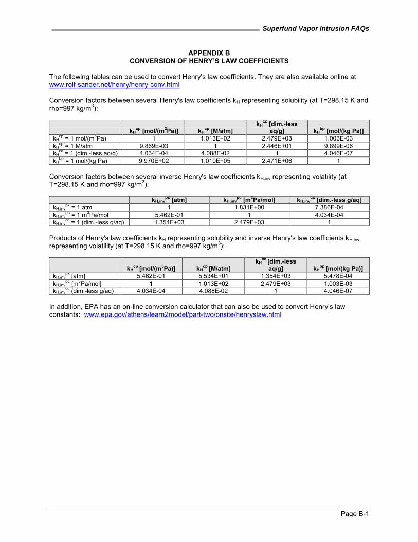
Superfund Vapor Intrusion FAQs
Page B-1
APPENDIX B CONVERSION OF HENRY’S LAW COEFFICIENTS
The following tables can be used to convert Henry’s law coefficients. They are also available online at www.rolf-sander.net/henry/henry-conv.html Conversion factors between several Henry's law coefficients kH representing solubility (at T=298.15 K and rho=997 kg/m3):
kHcp [mol/(m3Pa)] kH
cp [M/atm] kH
cc [dim.-less aq/g] kH
bp [mol/(kg Pa)] kH
cp = 1 mol/(m3Pa) 1 1.013E+02 2.479E+03 1.003E-03 kH
cp = 1 M/atm 9.869E-03 1 2.446E+01 9.899E-06 kH
cc = 1 (dim.-less aq/g) 4.034E-04 4.088E-02 1 4.046E-07 kH
bp = 1 mol/(kg Pa) 9.970E+02 1.010E+05 2.471E+06 1 Conversion factors between several inverse Henry's law coefficients kH,inv representing volatility (at T=298.15 K and rho=997 kg/m3):
kH,invpx [atm] kH,inv
pc [m3Pa/mol] kH,invcc [dim.-less g/aq]
kH,invpx = 1 atm 1 1.831E+00 7.386E-04
kH,invpc = 1 m3Pa/mol 5.462E-01 1 4.034E-04
kH,invcc = 1 (dim.-less g/aq) 1.354E+03 2.479E+03 1
Products of Henry's law coefficients kH representing solubility and inverse Henry's law coefficients kH,inv representing volatility (at T=298.15 K and rho=997 kg/m3):
kHcp [mol/(m3Pa)] kH
cp [M/atm] kH
cc [dim.-less aq/g] kH
bp [mol/(kg Pa)] kH,inv
px [atm] 5.462E-01 5.534E+01 1.354E+03 5.478E-04 kH,inv
pc [m3Pa/mol] 1 1.013E+02 2.479E+03 1.003E-03 kH,inv
cc (dim.-less g/aq) 4.034E-04 4.088E-02 1 4.046E-07 In addition, EPA has an on-line conversion calculator that can also be used to convert Henry’s law constants: www.epa.gov/athens/learn2model/part-two/onsite/henryslaw.html
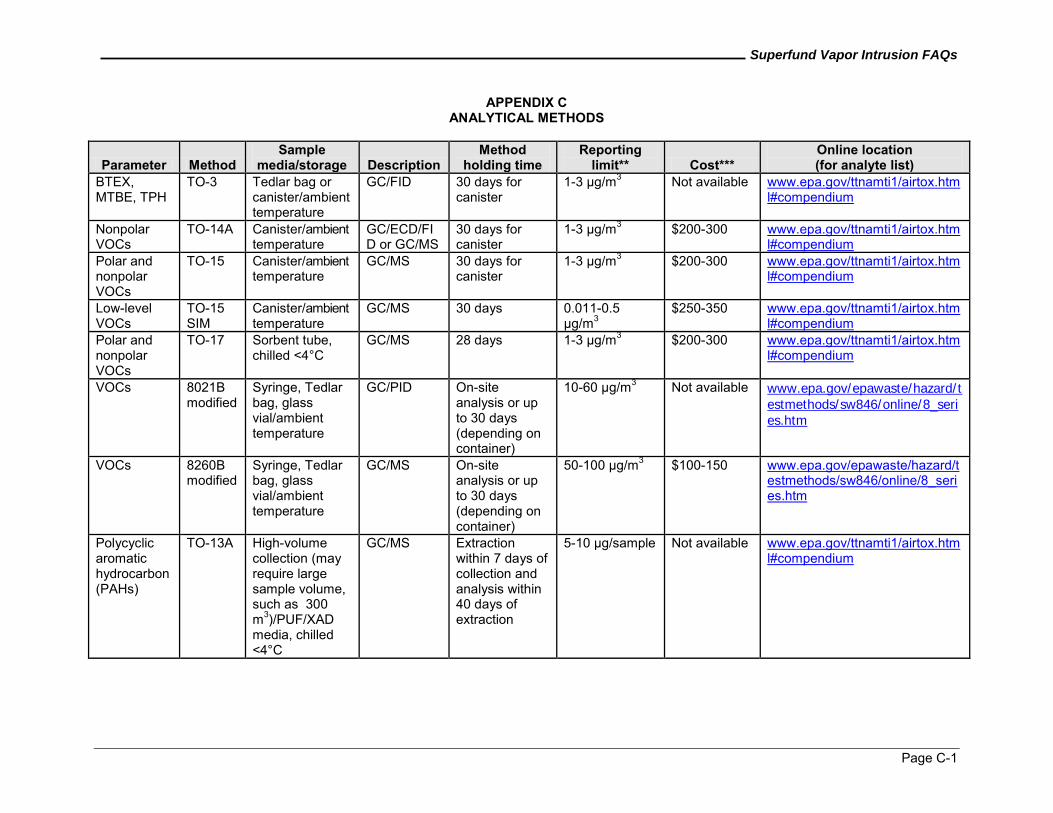
Superfund Vapor Intrusion FAQs
Page C-1
APPENDIX C ANALYTICAL METHODS
Parameter Method Sample
media/storage Description Method
holding time Reporting
limit** Cost*** Online location (for analyte list)
BTEX, MTBE, TPH
TO-3 Tedlar bag or canister/ambient temperature
GC/FID 30 days for canister
1-3 µg/m3 Not available www.epa.gov/ttnamti1/airtox.html#compendium
Nonpolar VOCs
TO-14A Canister/ambient temperature
GC/ECD/FID or GC/MS
30 days for canister
1-3 µg/m3 $200-300 www.epa.gov/ttnamti1/airtox.html#compendium
Polar and nonpolar VOCs
TO-15 Canister/ambient temperature
GC/MS 30 days for canister
1-3 µg/m3 $200-300 www.epa.gov/ttnamti1/airtox.html#compendium
Low-level VOCs
TO-15 SIM
Canister/ambient temperature
GC/MS 30 days 0.011-0.5 µg/m3
$250-350 www.epa.gov/ttnamti1/airtox.html#compendium
Polar and nonpolar VOCs
TO-17 Sorbent tube, chilled <4°C
GC/MS 28 days 1-3 µg/m3 $200-300 www.epa.gov/ttnamti1/airtox.html#compendium
VOCs 8021B modified
Syringe, Tedlar bag, glass vial/ambient temperature
GC/PID On-site analysis or up to 30 days (depending on container)
10-60 µg/m3 Not available www.epa.gov/epawaste/hazard/t
estmethods/sw846/online/8_series.htm
VOCs 8260B modified
Syringe, Tedlar bag, glass vial/ambient temperature
GC/MS On-site analysis or up to 30 days (depending on container)
50-100 µg/m3 $100-150 www.epa.gov/epawaste/hazard/testmethods/sw846/online/8_series.htm
Polycyclic aromatic hydrocarbon (PAHs)
TO-13A High-volume collection (may require large sample volume, such as 300 m3)/PUF/XAD media, chilled <4°C
GC/MS Extraction within 7 days of collection and analysis within 40 days of extraction
5-10 µg/sample Not available www.epa.gov/ttnamti1/airtox.html#compendium
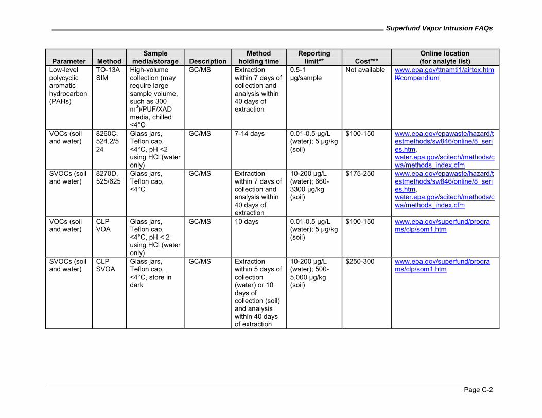
Superfund Vapor Intrusion FAQs
Page C-2
Parameter Method Sample
media/storage Description Method
holding time Reporting
limit** Cost*** Online location (for analyte list)
Low-level polycyclic aromatic hydrocarbon (PAHs)
TO-13A SIM
High-volume collection (may require large sample volume, such as 300 m3)/PUF/XAD media, chilled <4°C
GC/MS Extraction within 7 days of collection and analysis within 40 days of extraction
0.5-1 µg/sample
Not available www.epa.gov/ttnamti1/airtox.html#compendium
VOCs (soil and water)
8260C, 524.2/524
Glass jars, Teflon cap, <4°C, pH <2 using HCl (water only)
GC/MS 7-14 days 0.01-0.5 µg/L (water); 5 µg/kg (soil)
$100-150 www.epa.gov/epawaste/hazard/testmethods/sw846/online/8_series.htm, water.epa.gov/scitech/methods/cwa/methods_index.cfm
SVOCs (soil and water)
8270D, 525/625
Glass jars, Teflon cap, <4°C
GC/MS Extraction within 7 days of collection and analysis within 40 days of extraction
10-200 µg/L (water); 660-3300 µg/kg (soil)
$175-250 www.epa.gov/epawaste/hazard/testmethods/sw846/online/8_series.htm, water.epa.gov/scitech/methods/cwa/methods_index.cfm
VOCs (soil and water)
CLP VOA
Glass jars, Teflon cap, <4°C, pH < 2 using HCl (water only)
GC/MS 10 days 0.01-0.5 µg/L (water); 5 µg/kg (soil)
$100-150 www.epa.gov/superfund/programs/clp/som1.htm
SVOCs (soil and water)
CLP SVOA
Glass jars, Teflon cap, <4°C, store in dark
GC/MS Extraction within 5 days of collection (water) or 10 days of collection (soil) and analysis within 40 days of extraction
10-200 µg/L (water); 500-5,000 µg/kg (soil)
$250-300 www.epa.gov/superfund/programs/clp/som1.htm
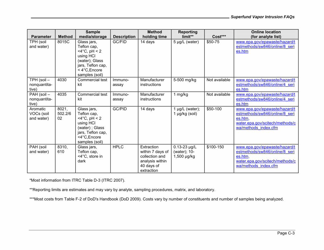
Superfund Vapor Intrusion FAQs
Page C-3
Parameter Method Sample
media/storage Description Method
holding time Reporting
limit** Cost*** Online location (for analyte list)
TPH (soil and water)
8015C Glass jars, Teflon cap, <4°C, pH < 2 using HCl (water); Glass jars, Teflon cap, < 4°C,Encore samples (soil)
GC/FID 14 days 5 µg/L (water) $50-75 www.epa.gov/epawaste/hazard/testmethods/sw846/online/8_series.htm
TPH (soil – nonquantita-tive)
4030 Commercial test kit
Immuno-assay
Manufacturer instructions
5-500 mg/kg Not available www.epa.gov/epawaste/hazard/testmethods/sw846/online/4_series.htm
PAH (soil – nonquantita-tive)
4035 Commercial test kit
Immuno-assay
Manufacturer instructions
1 mg/kg Not available www.epa.gov/epawaste/hazard/testmethods/sw846/online/4_series.htm
Aromatic VOCs (soil and water)
8021, 502.2/602
Glass jars, Teflon cap, <4°C, pH < 2 using HCl (water) ; Glass jars, Teflon cap, <4°C,Encore samples (soil)
GC/PID 14 days 1 µg/L (water); 1 µg/kg (soil)
$50-100 www.epa.gov/epawaste/hazard/testmethods/sw846/online/8_series.htm, water.epa.gov/scitech/methods/cwa/methods_index.cfm
PAH (soil and water)
8310, 610
Glass jars, Teflon cap, <4°C, store in dark
HPLC Extraction within 7 days of collection and analysis within 40 days of extraction
0.13-23 µg/L (water); 10-1,500 µg/kg
$100-150 www.epa.gov/epawaste/hazard/testmethods/sw846/online/8_series.htm, water.epa.gov/scitech/methods/cwa/methods_index.cfm
*Most information from ITRC Table D-3 (ITRC 2007). **Reporting limits are estimates and may vary by analyte, sampling procedures, matrix, and laboratory. ***Most costs from Table F-2 of DoD's Handbook (DoD 2009). Costs vary by number of constituents and number of samples being analyzed.