Embed Size (px)
Citation preview
Chapter 9-1
Chapter 9: Vapor and Combined Power Cycles
We consider power cycles where the working fluid undergoes a phasechange. The best example of this cycle is the steam power cycle wherewater (steam) is the working fluid.
Carnot Vapor Cycle
The heat engine may be composed of the following components.
Steam Power Cycle
Turbine
2
PumpCondenser
Wturb
1
3
QI n
Qout
4
Boiler
Wp
Heat sourceTH > TL
QH
QL
Heat SinkTL
Heatengine Wnet
Chapter 9-2
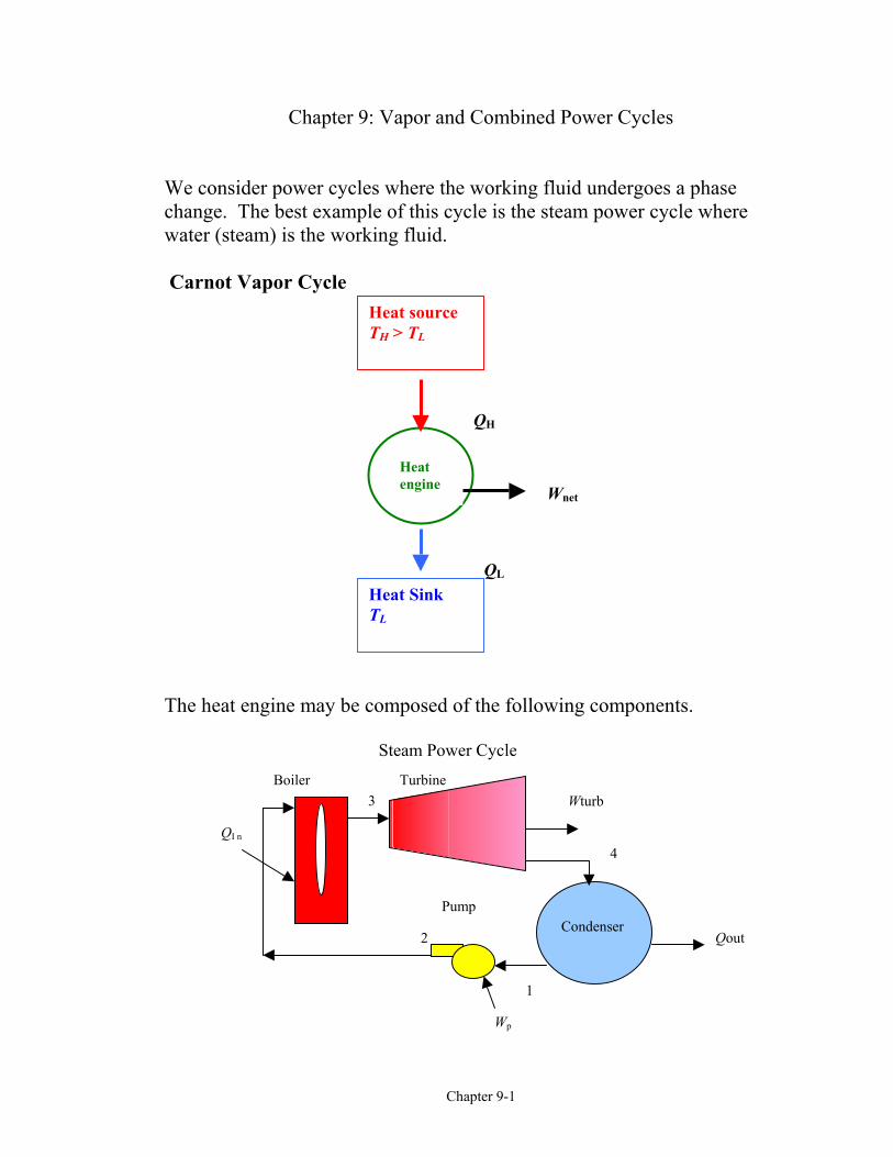
The working fluid, steam (water), undergoes a thermodynamic cycle from 1-2-3-4-1. The cycle is shown on the following T-s diagram.
The thermal efficiency of this cycle is given as
η th Carnotnet
in
out
in
L
H
WQ
TT
, = = −
= −
1
1
Note the effect of TH and TL on ηth, Carnot.• The larger the TH the larger the ηth, Carnot
• The smaller the TL the larger the ηth, Carnot
0.0 1.0 2.0 3.0 4.0 5.0 6.0 7.0 8.0 9.0 10.00
100
200
300
400
500
600
700700
s [kJ/kg-K]
T [C
]
6000 kPa
100 kPa
Carnot Vapor Cycle Using Steam
1
2 3
4
Chapter 9-3
To increase the thermal efficiency in any power cycle, we try to increase themaximum temperature at which heat is added.
Reasons why the Carnot cycle is not used:• Pumping process 1-2 requires the pumping of a mixture of saturated
liquid and saturated vapor at state 1 and the delivery of a saturated liquidat state 2.
• To superheat the steam to take advantage of a higher temperature,elaborate controls are required to keep TH constant while the steamexpands and does work.
To resolve the difficulties associated with the Carnot cycle, the Rankinecycle was devised.
Rankine Cycle
The simple Rankine cycle has the same component layout as the Carnotcycle shown above. The simple Rankine cycle continues the condensationprocess 4-1 until the saturated liquid line is reached.
Ideal Rankine Cycle Processes Process Description 1-2 Isentropic compression in pump 2-3 Constant pressure heat addition in boiler 3-4 Isentropic expansion in turbine 4-1 Constant pressure heat rejection in condenser
The T-s diagram for the Rankine cycle is given below. Locate the processesfor heat transfer and work on the diagram.
Chapter 9-4
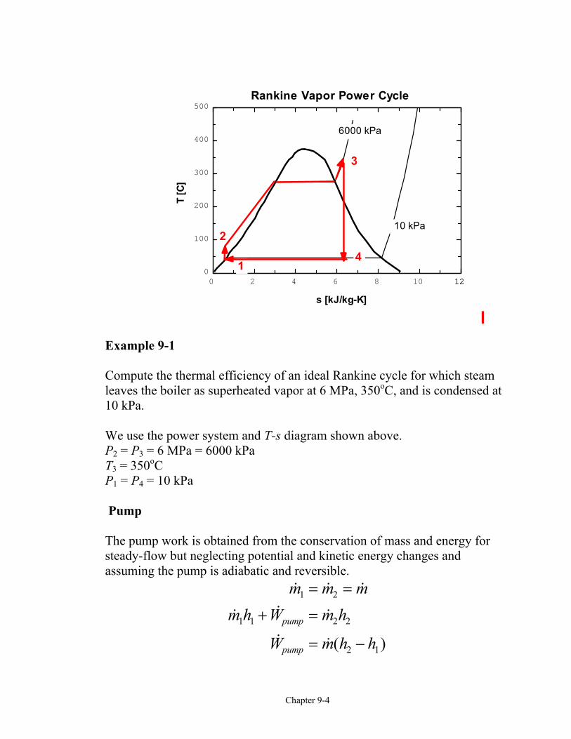
Example 9-1 Compute the thermal efficiency of an ideal Rankine cycle for which steamleaves the boiler as superheated vapor at 6 MPa, 350oC, and is condensed at10 kPa.
We use the power system and T-s diagram shown above.P2 = P3 = 6 MPa = 6000 kPaT3 = 350oCP1 = P4 = 10 kPa Pump
The pump work is obtained from the conservation of mass and energy forsteady-flow but neglecting potential and kinetic energy changes andassuming the pump is adiabatic and reversible.
( )
m m mm h W m h
W m h hpump
pump
1 2
1 1 2 2
2 1
= =
+ =
= −
0 2 4 6 8 10 12120
100
200
300
400
500
s [kJ/kg-K]
T [C
]
6000 kPa
10 kPa
Rankine Vapor Power Cycle
1
2
3
4
Chapter 9-5
Since the pumping process involves an incompressible liquid, state 2 is in thecompressed liquid region, we use a second method to find the pump work orthe ∆h across the pump.
Recall the property relation:dh = T ds + v dP
Since the ideal pumping process 1-2 is isentropic, ds = 0.
dh v dP
h h h v dP
=
= − = z∆ 2 1 1
2
The incompressible liquid assumption allows
v v consth h v P P
≅ =− ≅ −
1
2 1 1 2 1
.( )
The pump work is calculated from
( ) ( )
( )
W m h h mv P P
wW
mv P P
pump
pumppump
= − ≅ −
= = −
2 1 1 2 1
1 2 1
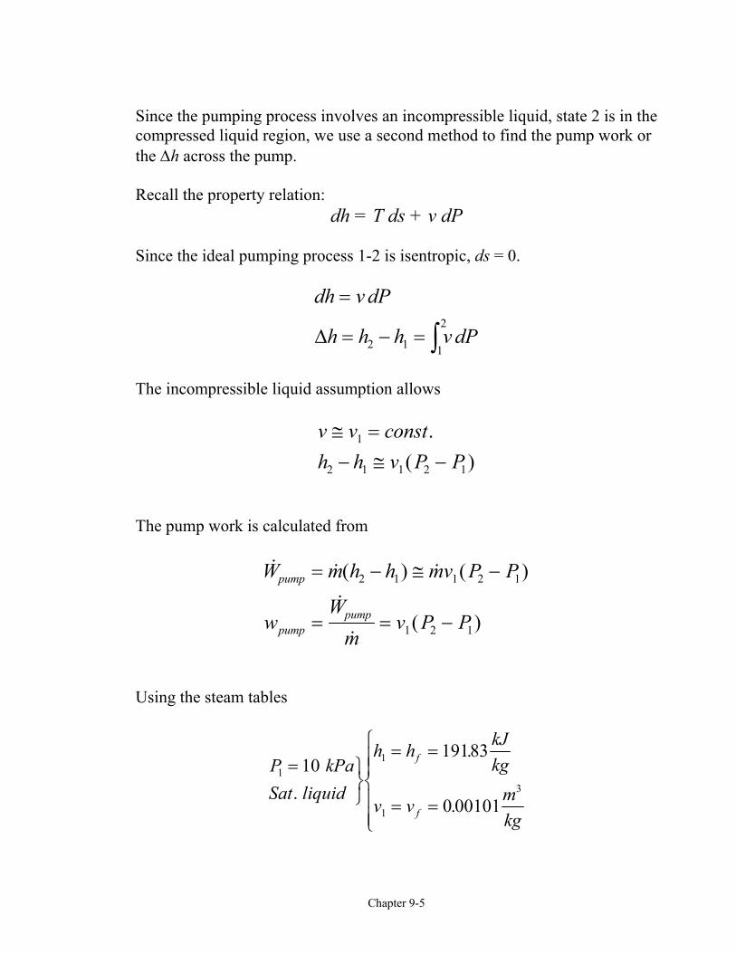
Using the steam tables
P kPaSat liquid
h h kJkg
v v mkg
f
f
11
1
3
1019183
0 00101
= UVW= =
= =
RS||
T||
.
.
.
Chapter 9-6
w v P P
mkg
kPa kJm kPa
kJkg
pump = −
= −
=
1 2 1
3
30 00101 6000 10
6 05
( )
. ( )
.
Now, h2 is found from
h w hkJkg
kJkg
kJkg
pump2 1
6 05 19183
197 88
= +
= +
=
. .
.
Boiler
To find the heat supplied in the boiler, we apply the steady-flowconservation of mass and energy to the boiler. If we neglect the potentialand kinetic energies, and note that no work is done on the steam in the boiler,then
( )
m m mm h Q m h
Q m h hin
in
2 3
2 2 3 3
3 2
= =
+ =
= −
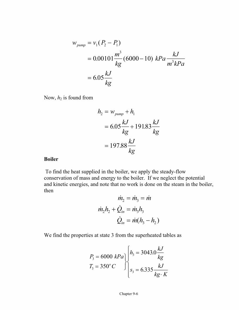
We find the properties at state 3 from the superheated tables as
P kPaT C
h kJkg
s kJkg K
o3
3
3
3
6000350
30430
6 335
=
=
UVW=
=⋅
RS||
T||
.
.
Chapter 9-7
The heat transfer per unit mass is
q Qm
h h
kJkg
kJkg
inin= = −
= −
=
( . . )
.
3 2
3040 3 197 88
28452
Turbine
The turbine work is obtained from the application of the conservation ofmass and energy for steady flow. We assume the process is adiabatic andreversible and neglect changes in kinetic and potential energies.
( )
m m mm h W m hW m h h
turb
turb
3 4
3 3 4 4
3 4
= =
= +
= −
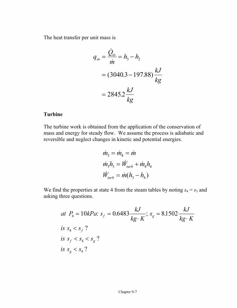
We find the properties at state 4 from the steam tables by noting s4 = s3 andasking three questions.
at P kPa s kJkg K
s kJkg K
is s sis s s sis s s
f g
f
f g
g
4
4
4
4
10 0 6483 81502= =⋅
=⋅
<
< <
<
: . ; .
??
?
Chapter 9-8
s s x s
xs s
s
f fg
f
fg
4 4
44 6 335 0 6493
7 50090 758
= +
=−
=−
=. .
..
h h x hkJkg
kJkg
kJkg
f fg4 4
19183 0 758 2584 7 19183
20056
= +
= + −
=
. . ( . . )
.
The turbine work per unit mass is
w h hkJkg
kJkg
turb = −
= −
=
3 4
30430 200563
1037 4
( . . )
.
The net work done by the cycle is
w w wkJkg
kJkg
net turb pump= −
= −
=
( . . )
.
1037 4 6 05
10314
Chapter 9-9
The thermal efficiency is
η thnet
in
wq
kJkgkJkg
or
=
=
=
10314
2845 2
0 363 36 3%
.
.
. .
Ways to improve the simple Rankine cycle efficiency:
• Superheat the vapor Average temperature is higher during heat addition. Moisture is reduced at turbine exit (we want x4 in the above example >
85 percent).
• Increase boiler pressure (for fixed maximum temperature)Availability of steam is higher at higher pressures.
Moisture is increased at turbine exit.• Lower condenser pressure
Less energy is lost to surroundings. Moisture is increased at turbine exit.
Extra Assignment
For the above example, find the heat rejected by the cycle and evaluate thethermal efficiency from
η thnet
in
out
in
wq
= = −1
Chapter 9-10
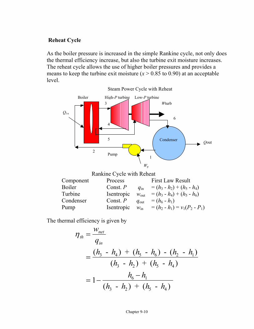
Reheat Cycle
As the boiler pressure is increased in the simple Rankine cycle, not only doesthe thermal efficiency increase, but also the turbine exit moisture increases.The reheat cycle allows the use of higher boiler pressures and provides ameans to keep the turbine exit moisture (x > 0.85 to 0.90) at an acceptablelevel.
Rankine Cycle with ReheatComponent Process First Law Result Boiler Const. P qin = (h3 - h2) + (h5 - h4) Turbine Isentropic wout = (h3 - h4) + (h5 - h6) Condenser Const. P qout = (h6 - h1) Pump Isentropic win = (h2 - h1) = v1(P2 - P1)
The thermal efficiency is given by
η thnet
in
wqh h h h h h
h h h hh h
h h h h
=
=
= −−
( - ) + ( - ) - ( - )( - ) + ( - )
( - ) + ( - )
3 4 5 6 2 1
3 2 5 4
6 1
3 2 5 4
1
5
4
Low-P turbineHigh-P turbine
2Pump
Condenser
Wturb
1
3
QI n
Qout
6
Boiler
Wp
Steam Power Cycle with Reheat
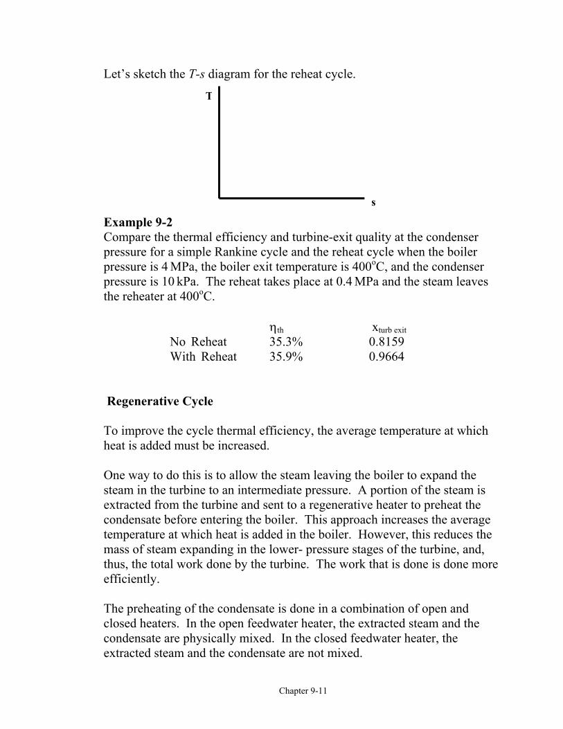
Let’s sketch the T-s diagram for the reheat cycle.
Example 9-2 Compare the thermpressure for a simppressure is 4 MPa, pressure is 10 kPa. the reheater at 400o
No ReWith
Regenerative Cyc
To improve the cycheat is added must
One way to do thissteam in the turbinextracted from the condensate before temperature at whimass of steam expathus, the total workefficiently.
The preheating of tclosed heaters. In condensate are phyextracted steam and
T
Chapter 9-11
al efficiency and turbine-exit qule Rankine cycle and the reheat the boiler exit temperature is 400 The reheat takes place at 0.4 MC.
ηth heat 35.3%
Reheat 35.9%
le
le thermal efficiency, the averagbe increased.
is to allow the steam leaving thee to an intermediate pressure. Aturbine and sent to a regenerativentering the boiler. This approach heat is added in the boiler. Hnding in the lower- pressure sta done by the turbine. The work
he condensate is done in a combthe open feedwater heater, the exsically mixed. In the closed fee the condensate are not mixed.
s
ality at the condensercycle when the boiler
oC, and the condenserPa and the steam leaves
xturb exit 0.8159 0.9664
e temperature at which
boiler to expand the portion of the steam ise heater to preheat thech increases the averageowever, this reduces theges of the turbine, and, that is done is done more
ination of open andtracted steam and the
dwater heater, the
Chapter 9-12
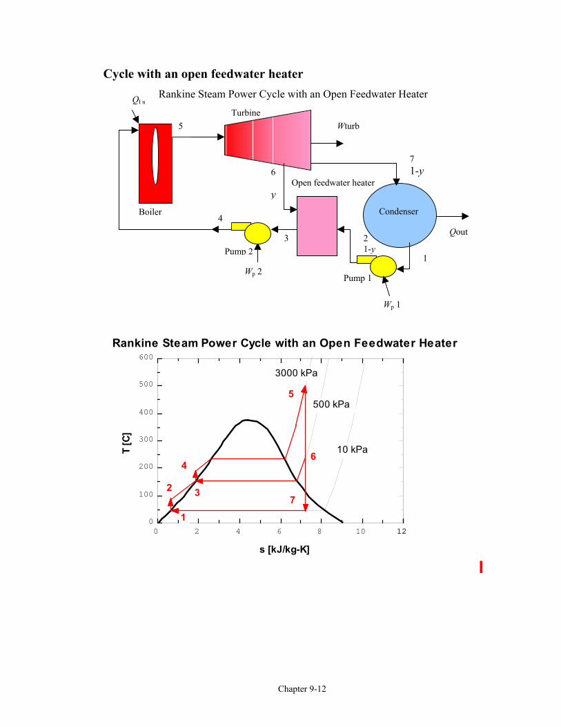
Cycle with an open feedwater heater Rankine Steam Power Cycle with an Open Feedwater Heater
Turbine
21-y
6 Open feedwater heatery
Pump 1
Pump 2
Condenser
Wturb
1
3
QI n
Qout4
71-y
Wp 2
Boiler
Wp 1
5
0 2 4 6 8 10 12120
100
200
300
400
500
600
s [kJ/kg-K]
T [C
]
3000 kPa
500 kPa
10 kPa
Rankine Steam Power Cycle with an Open Feedwater Heater
1
2 3
4
5
6
7
Chapter 9-13
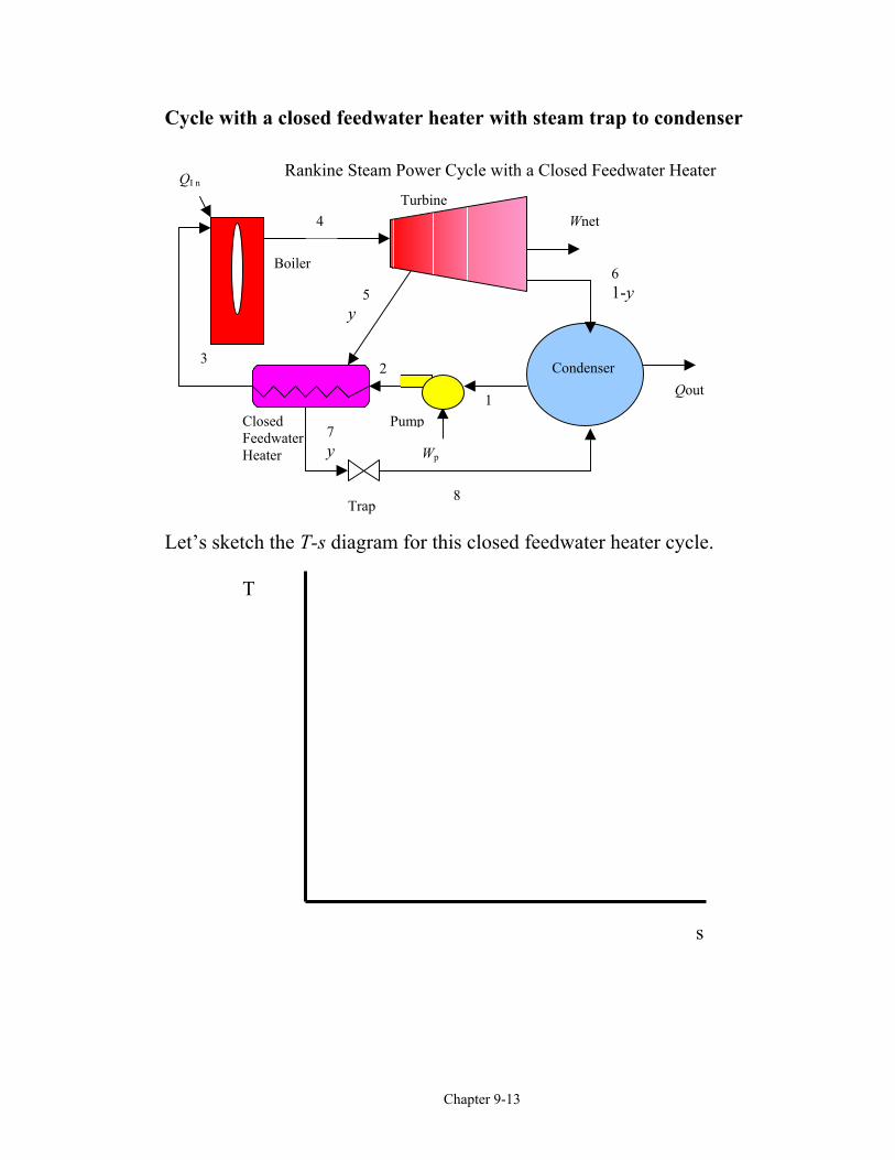
Cycle with a closed feedwater heater with steam trap to condenser
Let’s sketch the T-s diagram for this closed feedwater heater cycle.
ClosedFeedwaterHeater
7y
Rankine Steam Power Cycle with a Closed Feedwater Heater
Turbine
5y
2Pump
Condenser
Wnet
1
QI n
Qout2
61-y
Wp
3
Boiler
4
8Trap
T
s
Chapter 9-14
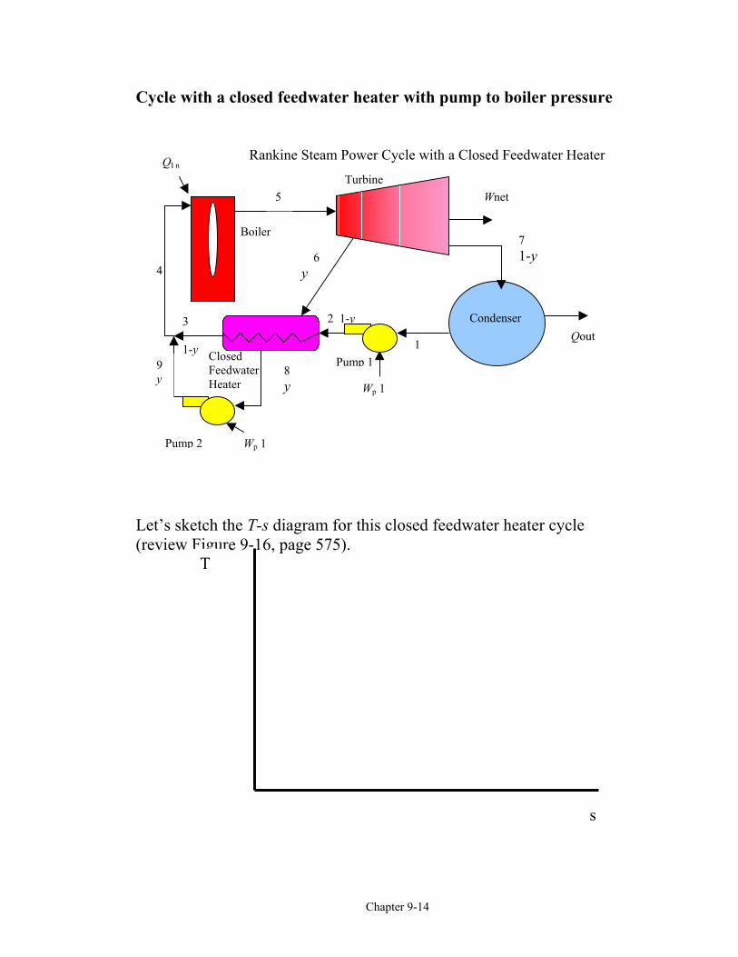
Cycle with a closed feedwater heater with pump to boiler pressure
Let’s sketch the T-s diagram for this closed feedwater heater cycle(review Figure 9-16, page 575).
9
4
2 1-y
ClosedFeedwaterHeater
8y
Rankine Steam Power Cycle with a Closed Feedwater Heater
Turbine
6y
2Pump 1
Condenser
Wnet
1
QI n
Qout
71-y
Wp 1
3
1-y
Boiler
5
Pump 2 Wp 1
9y
T
s
Chapter 9-15
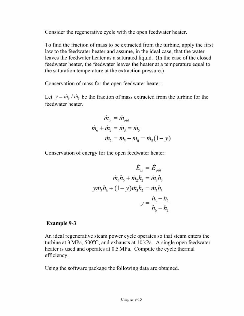
Consider the regenerative cycle with the open feedwater heater.
To find the fraction of mass to be extracted from the turbine, apply the firstlaw to the feedwater heater and assume, in the ideal case, that the waterleaves the feedwater heater as a saturated liquid. (In the case of the closedfeedwater heater, the feedwater leaves the heater at a temperature equal tothe saturation temperature at the extraction pressure.)
Conservation of mass for the open feedwater heater:
Let y m m= /6 5 be the fraction of mass extracted from the turbine for thefeedwater heater.
( )
m mm m m m
m m m m y
in out=+ = =
= − = −6 2 3 5
2 5 6 5 1
Conservation of energy for the open feedwater heater:
( )
E Em h m h m h
ym h y m h m h
y h hh h
in out=+ =
+ − =
=−−
6 6 2 2 3 3
5 6 5 2 5 3
3 2
6 2
1
Example 9-3 An ideal regenerative steam power cycle operates so that steam enters theturbine at 3 MPa, 500oC, and exhausts at 10 kPa. A single open feedwaterheater is used and operates at 0.5 MPa. Compute the cycle thermalefficiency.
Using the software package the following data are obtained.
Chapter 9-16
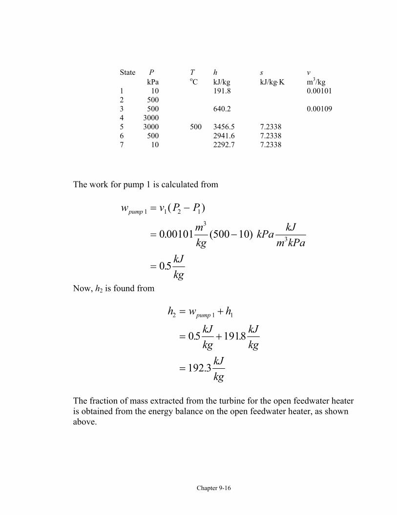
State P T h s v kPa oC kJ/kg kJ/kg⋅K m3/kg
1 10 191.8 0.001012 500 3 500 640.2 0.00109 4 3000 5 3000 500 3456.5 7.2338 6 500 2941.6 7.2338 7 10 2292.7 7.2338
The work for pump 1 is calculated from
w v P P
mkg
kPa kJm kPa
kJkg
pump 1 1 2 1
3
30 00101 10
05
= −
= −
=
( )
. (500 )
.
Now, h2 is found from
h w h
kJkg
kJkg
kJkg
pump2 1 1
05 1918
192 3
= +
= +
=
. .
.
The fraction of mass extracted from the turbine for the open feedwater heateris obtained from the energy balance on the open feedwater heater, as shownabove.
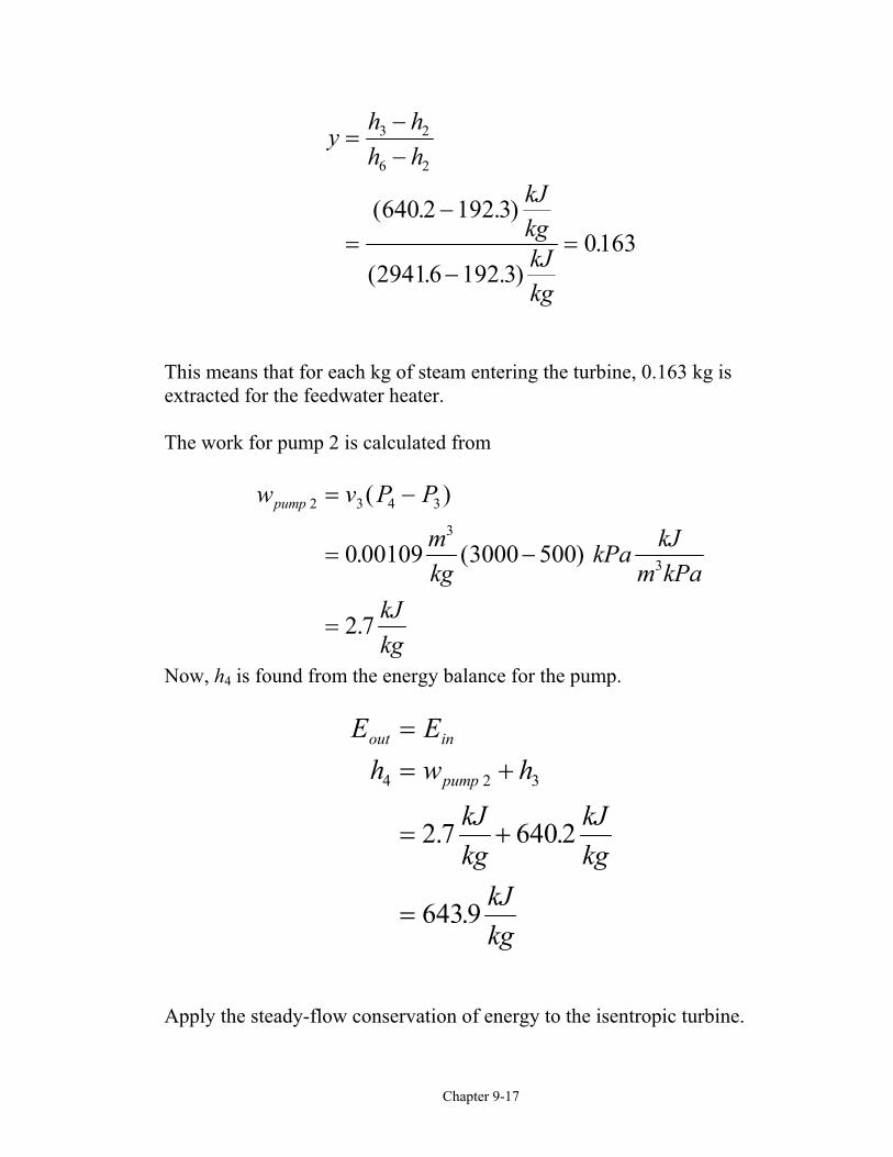
Chapter 9-17
y h hh h
kJkgkJkg
=−−
=−
−=
3 2
6 2
640 2 192 3
29416 192 30163
( . . )
( . . ).
This means that for each kg of steam entering the turbine, 0.163 kg isextracted for the feedwater heater.
The work for pump 2 is calculated from
w v P P
mkg
kPa kJm kPa
kJkg
pump 2 3 4 3
3
30 00109 3000 500
2 7
= −
= −
=
( )
. ( )
.
Now, h4 is found from the energy balance for the pump.
E Eh w h
kJkg
kJkg
kJkg
out in
pump
== +
= +
=
4 2 3
2 7 640 2
6439
. .
.
Apply the steady-flow conservation of energy to the isentropic turbine.
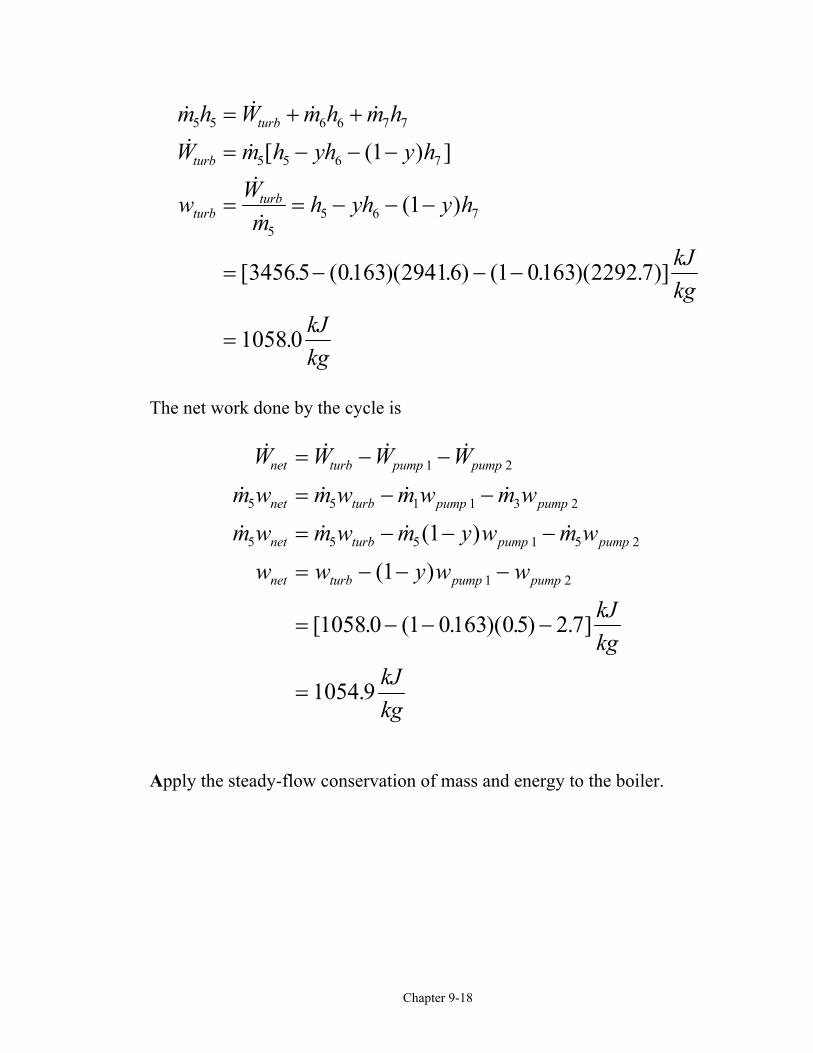
Chapter 9-18
[ ( ) ]
( )
[ . ( . )( . ) ( . )( . )]
.
m h W m h m hW m h yh y h
w Wm
h yh y h
kJkg
kJkg
turb
turb
turbturb
5 5 6 6 7 7
5 5 6 7
55 6 7
1
1
34565 0163 29416 1 0163 2292 7
1058 0
= + +
= − − −
= = − − −
= − − −
=
The net work done by the cycle is
( )
( )
[ . ( . )( . ) . ]
.
W W W W
m w m w m w m w
m w m w m y w m w
w w y w w
kJkg
kJkg
net turb pump pump
net turb pump pump
net turb pump pump
net turb pump pump
= − −
= − −
= − − −
= − − −
= − − −
=
1 2
5 5 1 1 3 2
5 5 5 1 5 2
1 2
1
1
1058 0 1 0163 05 2 7
1054 9
Apply the steady-flow conservation of mass and energy to the boiler.
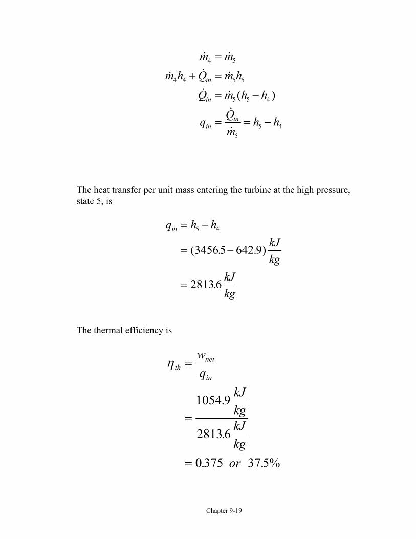
Chapter 9-19
( )
m mm h Q m h
Q m h h
q Qm
h h
in
in
inin
4 5
4 4 5 5
5 5 4
55 4
=
+ =
= −
= = −
The heat transfer per unit mass entering the turbine at the high pressure,state 5, is
q h hkJkg
kJkg
in = −
= −
=
5 4
3456 5 642 9
28136
( . . )
.
The thermal efficiency is
η thnet
in
wq
kJkgkJkg
or
=
=
=
1054 9
2813 6
0 375 37 5%
.
.
. .
Chapter 9-20
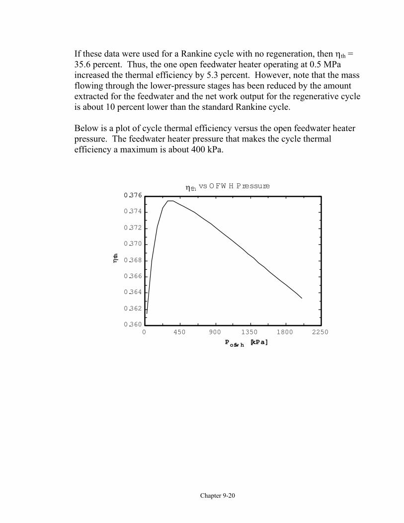
If these data were used for a Rankine cycle with no regeneration, then ηth =35.6 percent. Thus, the one open feedwater heater operating at 0.5 MPaincreased the thermal efficiency by 5.3 percent. However, note that the massflowing through the lower-pressure stages has been reduced by the amountextracted for the feedwater and the net work output for the regenerative cycleis about 10 percent lower than the standard Rankine cycle.
Below is a plot of cycle thermal efficiency versus the open feedwater heaterpressure. The feedwater heater pressure that makes the cycle thermalefficiency a maximum is about 400 kPa.
0 450 900 1350 1800 22500.360
0.362
0.364
0.366
0.368
0.370
0.372
0.374
0.3760.376
Pofw h [kPa]
η th
ηth vs O FW H Pressure
Chapter 9-21
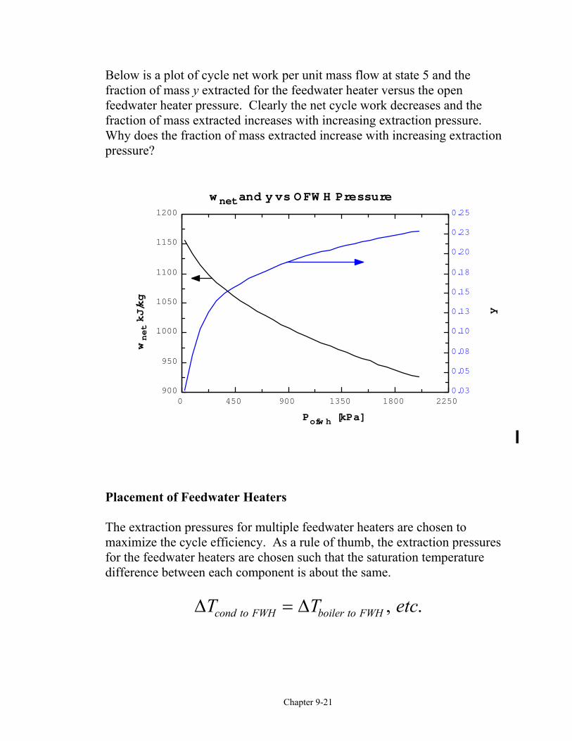
Below is a plot of cycle net work per unit mass flow at state 5 and thefraction of mass y extracted for the feedwater heater versus the openfeedwater heater pressure. Clearly the net cycle work decreases and thefraction of mass extracted increases with increasing extraction pressure.Why does the fraction of mass extracted increase with increasing extractionpressure?
Placement of Feedwater Heaters
The extraction pressures for multiple feedwater heaters are chosen tomaximize the cycle efficiency. As a rule of thumb, the extraction pressuresfor the feedwater heaters are chosen such that the saturation temperaturedifference between each component is about the same.
∆ ∆T T etccond to FWH boiler to FWH= , .
0 450 900 1350 1800 2250900
950
1000
1050
1100
1150
1200
0.03
0.05
0.08
0.10
0.13
0.15
0.18
0.20
0.23
0.25
Pofw h [kPa]
wnet kJ/kg
y
w net and y vs O FW H Pressure
Chapter 9-22
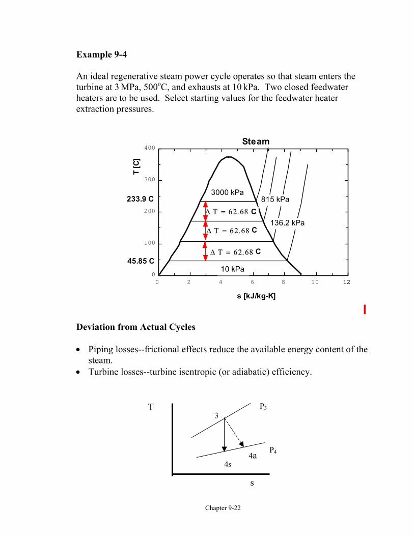
Example 9-4
An ideal regenerative steam power cycle operates so that steam enters theturbine at 3 MPa, 500oC, and exhausts at 10 kPa. Two closed feedwaterheaters are to be used. Select starting values for the feedwater heaterextraction pressures.
Deviation from Actual Cycles
• Piping losses--frictional effects reduce the available energy content of thesteam.
• Turbine losses--turbine isentropic (or adiabatic) efficiency.
0 2 4 6 8 10 12120
100
200
300
400
s [kJ/kg-K]
T [C
]
3000 kPa 815 kPa
136.2 kPa
10 kPa
Steam
∆ Τ = 62.68
∆ Τ = 62.68
∆ Τ = 62.68
C
C
C
233.9 C
45.85 C
4a4s
3
s
T P3
P4
Chapter 9-23
η turbactual
isentropic
a
s
ww
h hh h
= =−−
3 4
3 4
The actual enthalpy at the turbine exit (needed for the energy analysis of thenext component) is
h h h ha turb s4 3 3 4= − −η ( )
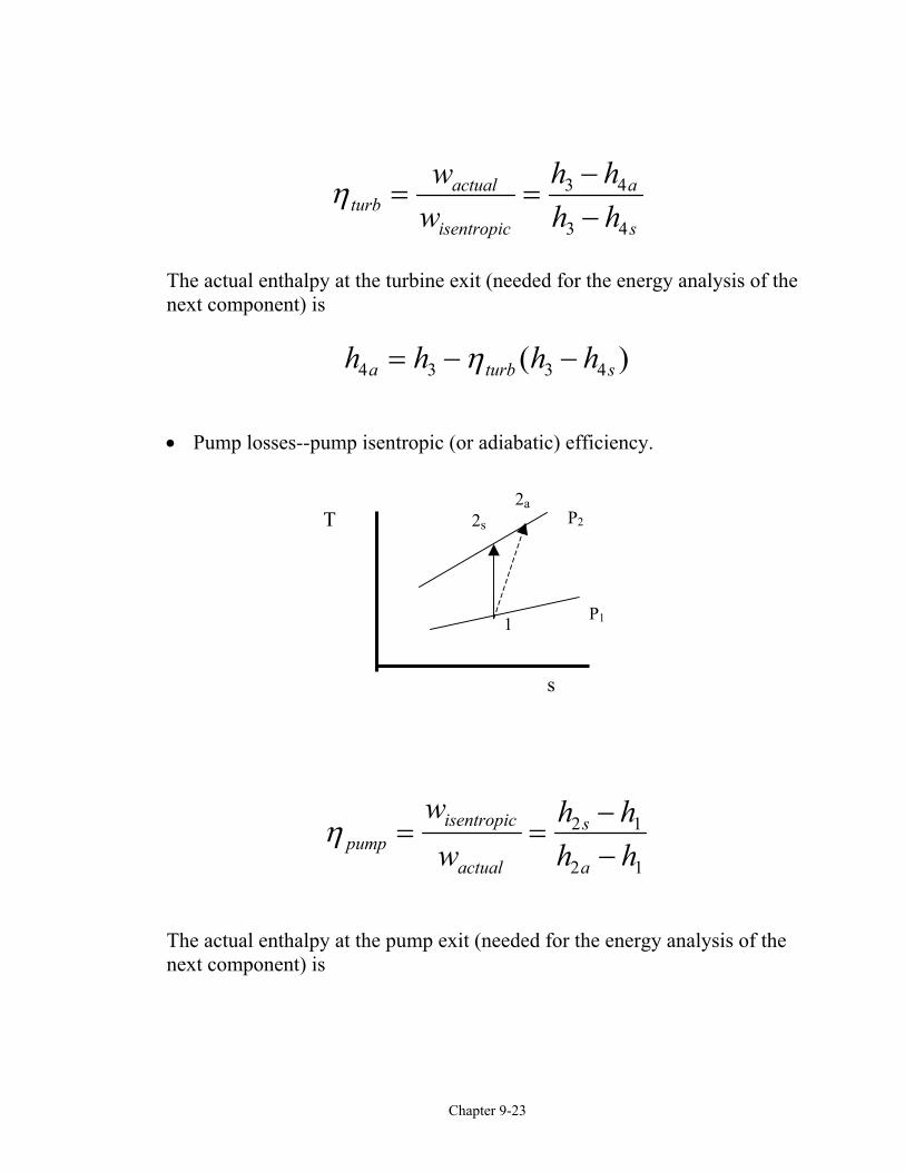
• Pump losses--pump isentropic (or adiabatic) efficiency.
η pumpisentropic
actual
s
a
ww
h hh h
= =−−
2 1
2 1
The actual enthalpy at the pump exit (needed for the energy analysis of thenext component) is
2a2s
1
s
T P2
P1
Chapter 9-24
h h h hapump
s2 1 2 11
= + −η
( )
• Condenser losses--relatively small losses that result from cooling thecondensate below the saturation temperature in the condenser.