Embed Size (px)
Citation preview

Vapor Recovery
1
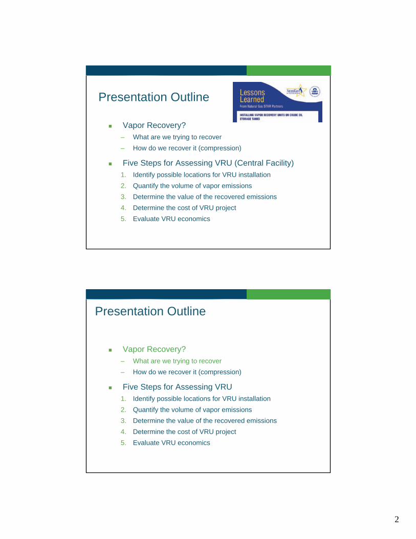
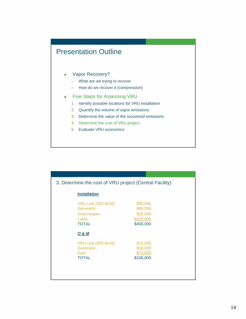
Presentation Outline
Vapor Recovery? – What are we trying to recover – How do we recover it (compression)
Five Steps for Assessing VRU (Central Facility) 1. Identify possible locations for VRU installation 2. Quantify the volume of vapor emissions 3. Determine the value of the recovered emissions 4. Determine the cost of VRU project 5. Evaluate VRU economics
Presentation Outline
Vapor Recovery? – What are we trying to recover – How do we recover it (compression)
Five Steps for Assessing VRU1. Identify possible locations for VRU installation 2. Quantify the volume of vapor emissions 3. Determine the value of the recovered emissions 4. Determine the cost of VRU project 5. Evaluate VRU economics
2

What are we trying to recover
Methane – $$$$ – Natural Gas is a limited resource – Identified as an greenhouse gas
Volatile Organic Compounds (VOC) – $$$$ – Natural Gas is a limited resource – Contributes to the global concentration of ozone (O3)
Ozone is an air pollutant associated with respiratory health issues
Hazardous Air Pollutants (HAP) – Benzene, Toluene, Ethyl Benzene, Xylene (BTEX) – Hydrogen Sulfide (H2S)
What are we trying to recover
ATM Storage Tank Vapors Flash Losses – Occurs from pressure drop from a higher pressure vessels to the ATM tank
Breathing Losses – Occurs from ambient temperature changes
Working Losses – Occurs from changing tank fluid levels and agitation of tank contents
Dehydration Still Non Condensible Glycol Absorbed Methane, VOC & HAP Stripping Gas Pump Gas
3
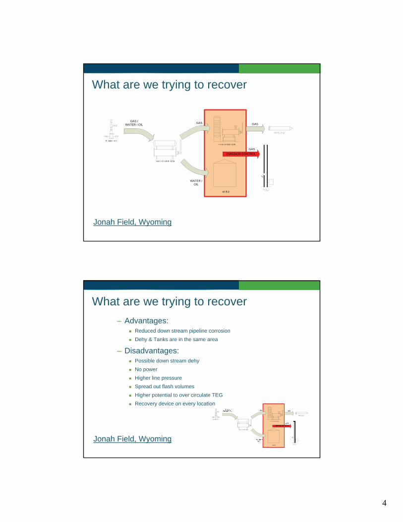
What are we trying to recover
Jonah Field, Wyoming
GAS / WATER / OIL
WATER / OIL
GAS GAS
EMISSION CONTROL GAS
What are we trying to recover
Jonah Field, Wyoming
– Advantages: Reduced down stream pipeline corrosion Dehy & Tanks are in the same area
– Disadvantages: Possible down stream dehy No power Higher line pressure Spread out flash volumes Higher potential to over circulate TEG Recovery device on every location
4

What are we trying to recover
Rifle, Colorado
What are we trying to recover
Rifle, Colorado
– Advantages: Reduce number Dehy Station Dehy & Tanks are in the same area Power at Station Lower line pressure More consistent line pressure
– Disadvantages: Gathering pipeline corrosion Spread out well flash volumes No power at location Possible tank emission control on every location VRU has to be sized for pigging volumes
5
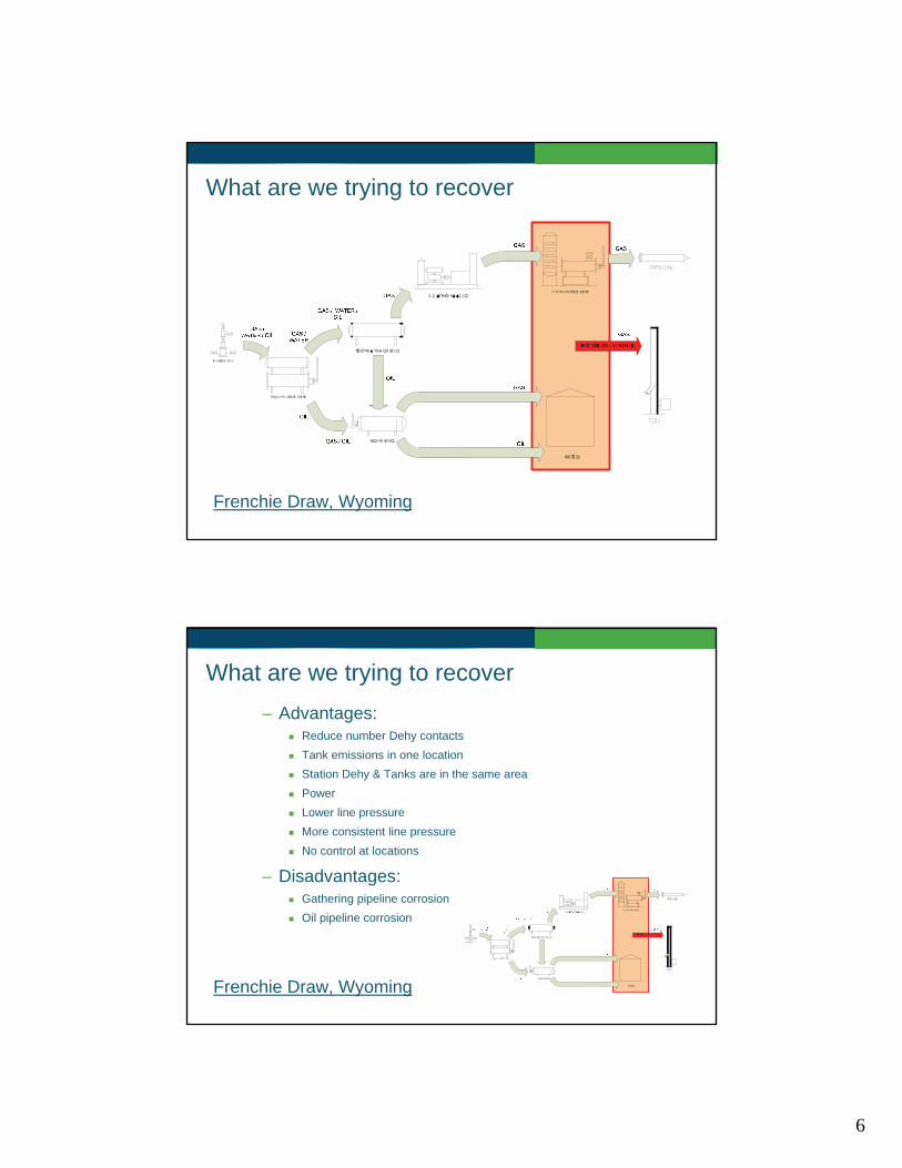
What are we trying to recover
Frenchie Draw, Wyoming
What are we trying to recover
Frenchie Draw, Wyoming
– Advantages: Reduce number Dehy contacts Tank emissions in one location Station Dehy & Tanks are in the same area Power Lower line pressure More consistent line pressure No control at locations
– Disadvantages: Gathering pipeline corrosion Oil pipeline corrosion
6

Presentation Outline
Vapor Recovery? – What are we trying to recover – How do we recover it (compression)
Five Steps for Assessing VRU1. Identify possible locations for VRU installation 2. Quantify the volume of vapor emissions 3. Determine the value of the recovered emissions 4. Determine the cost of VRU project 5. Evaluate VRU economics
How do we recover it
Reciprocating Compressors: – Advantages:
High Volumes (excess of 20 MMSCFD) High Pressures (diff 2000-3000 psig)
– Disadvantages: Low suction pressure results in large first stage cylinder Inefficient at low pressure Rings and valve fail in wet gas application Control is difficult at atmospheric pressure
DATA SOURCE: HY-BON Engineering Company, Inc.
7

How do we recover it (Compressors)
Rotary Vanes Compressors: – Advantages:
Excellent for relatively high volumes and relatively low differential pressures (0.015 – 2 MMSCFD)
Efficient at low pressures Can handle wet gas relatively easy Comparatively low initial cost and ongoing maintenance
– Disadvantages: Limited as to discharge pressure (60 psig differential) Limited as to suction temperature capabilities (120 F) Free liquid causes blade breakage problems
DATA SOURCE: HY-BON Engineering Company, Inc.
How do we recover it (Compressors)
Flooded Screws: – Advantages:
Excellent in a large volume/medium differential pressure range (0.02-2.5 MMSCFD)
Can handle wet gas better than rotary vanes Excellent temperature control for controlling condensate fallout (180 F)
– Disadvantages: Higher maintenance Higher operational expense (oil, filters, etc.) Extremely limited on discharge pressure Used primarily in vacuum applications
DATA SOURCE: HY-BON Engineering Company, Inc.
8

Presentation Outline
Vapor Recovery? – What are we trying to recover – How do we recover it (compression)
Five Steps for Assessing VRU 1. Identify possible locations for VRU installation 2. Quantify the volume of vapor emissions 3. Determine the value of the recovered emissions 4. Determine the cost of VRU project 5. Evaluate VRU economics
1. Identify possible locations for VRU installation
Frenchie Draw, Wyoming (Central Facility)
9

Presentation Outline
Vapor Recovery? – What are we trying to recover – How do we recover it (compression)
Five Steps for Assessing VRU1. Identify possible locations for VRU installation 2. Quantify the volume of vapor emissions 3. Determine the value of the recovered emissions 4. Determine the cost of VRU project 5. Evaluate VRU economics
2. Quantify the volume of vapor emissions (Central Facility)
OIL
OIL
200 PSIG
125 PSIG
40 PSIG
OIL
1
2
3
4 5
ATM ATM
GAS
GAS GAS
ATM SUCTION 125 PSIG DISCHARGE
1 FLASH LOSS (125 PSIG - ATM PSIG)
2 FLASH LOSS (200 PSIG - ATM PSIG)
3 FLASH LOSS (40 PSIG – ATM)
4 WORKING & BREATHING LOSS
5 STILL VENT NON CONDENSIBLE
(AT WELL LOCATION)
GAS
10

2. Quantify the volume of vapor emissions (Central Facility)
OIL
OIL
200 PSIG
125 PSIG
40 PSIG
1
2
GAS
1 FLASH LOSS (125 PSIG - ATM PSIG)
2 FLASH LOSS (200 PSIG - ATM PSIG)
(AT WELL LOCATION)
ATM
900 Bbl/Day
100 Bbl/Day
Quantifying Treater Emissions 1. Field Pressurized Oil Sample 2. Determine Production Rates 3. Determine Vessel Operating Conditions 4. Flashed with Process Simulator
Inlet Separator/Treater Flash – 11 MSCFD
Production Unit/Treater Flash - 154 MSCFD
Total Treater Flash- 165 MSCFD
2. Quantify the volume of vapor emissions (Central Facility)
40 PSIG
OIL
3
4
ATM
GAS
3 FLASH LOSS (40 PSIG – ATM)
4 WORKING & BREATHING LOSS
ATM
Quantifying Tank Emissions 1. Field Pressurized Oil Sample 2. Know Production Rates 3. Know Vessel Operating Conditions 4. Flashed with Process Simulator 5. Used E&P Tank for Working Loss 6. Used E&P Tank for Breathing Loss
Total Tank Flash- 61 MSCFD
11

2. Quantify the volume of vapor emissions (Central Facility)
5
ATM
5 STILL VENT NON CONDENSABLES
GAS
ATM
Total Treater Flash- 58 MSCFD
Quantifying Dehy Emissions 1. Field Extended Gas Analysis (w/ BTEX) 2. Know Production Rates 3. Know System Operating Conditions 4. Use GRI-GLYCalc
2. Quantify the volume of vapor emissions (Central Facility)
165 MSCFD
61 MSCFD
58 MSCFD
Total Emissions- 284 MSCFD
12

Presentation Outline
Vapor Recovery? – What are we trying to recover – How do we recover it (compression)
Five Steps for Assessing VRU1. Identify possible locations for VRU installation 2. Quantify the volume of vapor emissions 3. Determine the value of the recovered emissions 4. Determine the cost of VRU project 5. Evaluate VRU economics
3. Determine the value of the recovered emissions (Central Facility)
R = Q X P
R = The gross revenue
Q = The rate of vapor recovery (Mcf/day)
P = The price of natural gas
Calculate:
Q = 270 Mcfd (95% of 284)
P = $8.00/Mcf
R = 270 Mcfd X $8/Mcf =
$2,160/day
$65,700/month
$788,400/year
13
Presentation Outline
Vapor Recovery? – What are we trying to recover – How do we recover it (compression)
Five Steps for Assessing VRU1. Identify possible locations for VRU installation 2. Quantify the volume of vapor emissions 3. Determine the value of the recovered emissions 4. Determine the cost of VRU project 5. Evaluate VRU economics
3. Determine the cost of VRU project (Central Facility)
Installation
VRU Unit (500 Mcfd) - $90,000 Generator- $85,000 Vent Header- $25,000 Labor- $200,000 TOTAL $400,000
O & M
VRU Unit (500 Mcfd) - $15,000 Generator- $18,000 Fuel- $73,000 TOTAL $106,000
14

Presentation Outline
Vapor Recovery? – What are we trying to recover – How do we recover it (compression)
Five Steps for Assessing VRU1. Identify possible locations for VRU installation 2. Quantify the volume of vapor emissions 3. Determine the value of the recovered emissions 4. Determine the cost of VRU project 5. Evaluate VRU economics
3. Evaluate VRU economics (Central Facility)
Capacity– 500 Mcfd
Installation Cost - $400,000
O&M- $106,000/yr
Value of Gas- $788,400/yr
Payback- 7 months
Return on Investment- 170%
15

What now?
Started rebuilding our vent system
Started measuring TOU volumes
Finalizing compression design
Questions?
16