Embed Size (px)
Citation preview

Zurich Open Repository andArchiveUniversity of ZurichMain LibraryStrickhofstrasse 39CH-8057 Zurichwww.zora.uzh.ch
Year: 2019
Variable fixation locking screw (VFLS): investigation of bone healing with adevice intended to optimize strain and micromotion for each phase of
fracture healing
Planzer, Katrin
Posted at the Zurich Open Repository and Archive, University of ZurichZORA URL: https://doi.org/10.5167/uzh-174361DissertationPublished Version
Originally published at:Planzer, Katrin. Variable fixation locking screw (VFLS): investigation of bone healing with a deviceintended to optimize strain and micromotion for each phase of fracture healing. 2019, University ofZurich, Vetsuisse Faculty.

Institut für Molekulare Mechanismen bei Krankheiten der Vetsuisse-Fakultät Universität Zürich
Direktor: Prof. Dr. med. vet. et phil. II Michael Hottiger
Musculoskeletal Research Unit (MSRU) Leiterin: Prof. Dr. med. vet. Brigitte von Rechenberg
Arbeit unter wissenschaftlicher Betreuung von
Dr. med. vet. Karina Klein, DVM-PhD, Musculoskeletal Research Unit (MSRU)
Variable Fixation Locking Screw (VFLS): Investigation of Bone Healing with a Device Intended to Optimize Strain and Micromotion
for each Phase of Fracture Healing
Inaugural-Dissertation
zur Erlangung der Doktorwürde der Vetsuisse-Fakultät Universität Zürich
vorgelegt von
Katrin Planzer
Tierärztin von Bürglen UR, Schweiz
genehmigt auf Antrag von
Prof. Dr. med. vet. Brigitte von Rechenberg, Referentin
Prof. Dr. Stephen Ferguson, Korreferent
2019


den Schafen dieser Studie


Index
i
Zusammenfassung ............................................................................................................ 1
Summary ........................................................................................................................... 2
1 Introduction ................................................................................................................. 3 1.1 Healthcare Expenditure ........................................................................................ 3 1.2 Clinical problem .................................................................................................. 3 1.3 Purpose of the study ............................................................................................. 4
2 Literature overview ..................................................................................................... 5 2.1 Fracture healing ................................................................................................... 5
2.1.1 Phase I: Inflammation ................................................................................... 5 2.1.2 Phase II: Soft callus formation ...................................................................... 5 2.1.3 Phase III: Hard callus formation ................................................................... 6 2.1.4 Phase IV: Remodeling .................................................................................. 6
2.2 Interfragmentary strain and micromotion – the most important parameters ....... 6 2.2.1 The interfragmentary strain .......................................................................... 6 2.2.2 Micromotion or Interfragmentary Movement (IFM) .................................... 8
2.3 Medical Devices .................................................................................................. 9 2.3.1 Standard LS ................................................................................................. 10 2.3.2 DLS (Dynamic Locking Screw) ................................................................. 10 2.3.3 FCL (Far Cortical Locking) Screw / Zimmer® MotionLoc® Screw ........... 11 2.3.4 VFLS (Variable Fixation Locking Screw) .................................................. 11
2.4 Animal as human model .................................................................................... 13
3 Materials and Methods .............................................................................................. 14 3.1 Structure of the Study ........................................................................................ 14
3.1.1 Study design and experimental animals ...................................................... 14 3.2 Characterization of Devices ............................................................................... 15
3.2.1 Characterization of Test Item (TI) and Reference Item (RI) ...................... 15 3.3 Animal Management .......................................................................................... 16
3.3.1 Animal Identification .................................................................................. 16 3.3.2 Anesthesia ................................................................................................... 17
3.4 Surgery ............................................................................................................... 18 3.4.1 Surgical procedure ...................................................................................... 18
3.5 Postoperative Management ................................................................................ 19 3.5.1 Diagnostic imaging ..................................................................................... 19 3.5.2 Cast and suspension system ........................................................................ 20 3.5.3 Medication .................................................................................................. 20 3.5.4 Fluorescence dyes ....................................................................................... 21
3.6 In-life observations and examinations ............................................................... 21 3.7 Post-mortem sample preparation ....................................................................... 22
3.7.1 Tissue harvest after sacrifice ....................................................................... 22 3.7.2 Sample preparation for transport ................................................................ 23 3.7.3 Sample preparation for histological analysis .............................................. 23
3.8 Evaluative procedures ........................................................................................ 26

Index
ii
3.8.1 Radiologic evaluation .................................................................................. 26 3.8.2 Biomechanical testing ................................................................................. 27 3.8.3 Histological evaluation ................................................................................ 28 3.8.4 Fluorescence ................................................................................................ 31 3.8.5 Histological analysis of the draining lymph nodes ..................................... 32 3.8.6 Statistical analysis ....................................................................................... 32
4 Results ....................................................................................................................... 33 4.1 Excluded animals ............................................................................................... 33 4.2 Surgery ............................................................................................................... 33 4.3 Postsurgical in-life observations ........................................................................ 34 4.4 Sacrifice .............................................................................................................. 35 4.5 Radiologic evaluation ......................................................................................... 36
4.5.1 Radiographs ................................................................................................. 36 4.5.2 Micro-CT ..................................................................................................... 41 4.5.3 Microradiographs ........................................................................................ 45
4.6 Biomechanical testing ........................................................................................ 45 4.7 Histological evaluation ....................................................................................... 46
4.7.1 Histomorphometry ...................................................................................... 46 4.7.2 Thin section evaluation (cis/trans): quantitative and semiquantitative analysis of local tissue effects (ISO) ....................................................................... 47 4.7.3 Fluorescence ................................................................................................ 49 4.7.4 Lymph node analysis ................................................................................... 51
5 Discussion ................................................................................................................. 52 5.1 Conclusion .......................................................................................................... 60
6 References ................................................................................................................. 61
7 Appendix ................................................................................................................... 65 7.1 Tables ................................................................................................................. 65
7.1.1 Material and Methods .................................................................................. 65 7.1.2 Results ......................................................................................................... 70
7.2 Figures ................................................................................................................ 77 7.2.1 Material and Methods .................................................................................. 77 7.2.2 Results ......................................................................................................... 81
Danksagung
Curriculum Vitae

Zusammenfassung
1
Zusammenfassung
In dieser experimentellen Studie wurde die Frakturheilung bei interner Fixation mittels
der „Variable Fixation Locking Screw“ (VFLS) evaluiert und mit der Lockingschraube
(LS) von DePuy Synthes verglichen. Das Schraubendesign der VFLS ermöglicht eine
Mikromotion nach 2-3 Wochen um die Knochenheilung zu stimulieren. Für den
Versuch wurde ein Schafmodell mit einer Tibiaosteotomie (3 mm Defekt fixiert mit 6-
Loch LCP) gewählt. Die operierten Beine der 12 Schafe wurden postoperativ geröntgt,
gecastet und die Schafe wurden für 3 Wochen ins Netz gehängt. Danach folgten
wöchentliche Röntgenaufnahmen und Castwechsel. Fluoreszenzfarbstoff wurde in
Woche 3 und 6, sowie 48-72h vor der Schlachtung injiziert. Nach der Schlachtung
wurden die Tibiae makroskopisch und radiologisch untersucht, sowie mittels µCT,
biomechanischen Tests und Histologie analysiert. Die Resultate haben aufgezeigt, dass
die VFLS eine biokompatible und sichere Schraube ist. Histologie- und
Fluoreszenzergebnisse zeigten, dass die VFLS durch Micromotion ein starkes
Remodeling über die ganze Tibia ausüben kann. Die VFLS wies signifikant mehr
endostalen Kallus (p=0.012) zwischen dem 3. und 4. Schraubenloch auf. In den
biomechanischen Tests erlangte die VFLS leicht bessere Ergebnisse. Es liegt die
Vermutung nahe, dass die VFLS wegen des starken Remodelings bei Patienten mit
einer Frakturheilungsstörung ein besseres Endergebnis erzielen könnte.

Summary
2
Summary
In this experimental study, fracture healing was evaluated by using the Variable
Fixation Locking Screw (VFLS) and comparing it to the Locking Screw (LS) of DePuy
Synthes. The special screw design of the VFLS allows micromotion after 2-3 weeks to
stimulate bone healing. A standardized tibia osteotomy model in sheep (90°, 3mm
fracture gap, fixed with 6-hole LCP) was selected for this study. The sheep were
suspended for 3 weeks. Radiographs were performed post-surgery and weekly after
three weeks in combination with cast changes. Fluorescent dyes were administered
subcutaneously in week 3 and 6, as well as 48-72h prior to sacrifice. After sacrifice, a
radiological and macroscopical examination as well as µCT, biomechanical testing and
histology analysis was performed.
The results showed that the VFLS is a biocompatible and safe screw. Histological and
fluorescence results showed that VFLS could provide a strong remodeling across the
whole tibia due to its micro motion. The VFLS showed a significantly (p=0.012,
histology) higher amount of endosteal callus between the 3rd and 4th screw hole. In the
biomechanical tests, the VFLS performed slightly better.
The VFLS could achieve a better outcome in patients predisposed for fracture failure
mainly due to the strong remodeling.

Introduction
3
1 Introduction
1.1 Healthcare Expenditure
Osteosynthesis failure has a tremendous impact on healthcare expenditure per patient in
all countries. Epidemiological data about delayed and non-unions in the literature vary
from 1-6% of patients with long-bone fractures1-4 to 5-15% of bone fractures as a
whole5. SUVA (schweizerische Unfallversicherung) collects information about
occurrence and treatment costs for fractures in Switzerland. The most expensive 10% of
the cases are finally responsible for 63% of the total insurance costs6. Therefore, it is
evident that any effort aiming at decreasing the average costs of treating the most
expensive 10% patients, namely those patients with complications and comorbidities,
would have a substantial impact on the average treatment costs.
Population ageing is taking place in nearly all countries of the world and the incidence
of bone fractures is known to significantly increase after the middle of the lifespan7. By
2050 the number of persons aged 80 years or older will be more than three times higher
than today8. Beside the normal effect of ageing on the bone tissue, the increasing
incidence of conditions impairing bone healing like diabetes9,10, obesity11 and several
other metabolic diseases significantly contributes to an already substantial problem12.
1.2 Clinical problem
The significant problem beside infections and screws cut out is represented by patients
with delayed unions (healing after 3 months according to FDA 1988) or non-unions (no
union after 8-9 months according to FDA 1988)13-16.
Clinicians identified potential risk factors that could be responsible for this failed
fracture healing response. While patient related factors (genetics and systemic
disorders), environment related factors (smoking, medication and alcohol), and injury
related factors (trauma impact, soft tissue involvement) are given patient conditions,
surgeons have an important influence on bone healing, defining the fracture treatment
modalities through choosing the best implant, surgical technique and post-operative
treatment12.
The entire bone healing process is driven by gradual changes in the strain of the forming
tissue and for each of the four phases of secondary fracture healing the ideal strain
levels are slightly different13,17. Plates and screws that are used today, are not
completely able to reproduce those changes in bone callus boundary conditions known
Introduction
4
to activate the mechano-metabolic signals boosting fracture healing. In fact, current
locking systems feature constant mechanical properties during the entire fracture
treatment, thus providing a constant strain to the forming callus during the whole
fracture healing period. If the allowed strain is not in the right range, the fracture will
not properly heal.
1.3 Purpose of the study
The variable fixation locking screw (VFLS) is a medical device especially designed to
take the different strain conditions into account, known to promote fracture healing
during its different phases. A resorbable sleeve is fixed under the screw head in a
position such that it is fully inserted in the cis cortex of a bone once implanted. Starting
from very stable conditions, this sleeve progressively decreases its mechanical
properties and dimensions. After an initial period of stability, the fixation of each
implanted sleeve decreases, leading to a progressive increase in interfragmentary
motion.
The primary goal of this study is to test the safety and efficacy of this new screw,
especially developed to address the risk of delayed and non-unions.
The secondary goal is to compare the performances of this new device with respect to
those of the standard locking screw (DePuy Synthes).
Finally, we aim at understanding if keeping the healing tissue in conditions known to
promote its maturation has potential to boost the entire healing process. Our long-term
goal is to allow a larger number of patients to return to their everyday life earlier and
thus decrease the number of extremely expensive patients with complications.

Literature overview
5
2 Literature overview
2.1 Fracture healing
Fractures can heal in two ways: through primary/direct or secondary/indirect bone
healing. Diaphyseal bone fractures often show secondary or indirect bone healing via an
external callus, which assists as support for the stabilization of the fracture. This
secondary bone healing includes four phases18,19:
2.1.1 Phase I: Inflammation
The inflammatory process starts immediately after fracture occurrence. It usually lasts
one to seven days after a fracture occurred. Due to the rupture of blood vessels in the
bone, periosteum and soft tissue, blood cells and inflammatory cells get into the fracture
gap. Furthermore, a fracture hematoma develops. Within hours, an inflammatory
cascade modulates the release of cytokines and growth factors. Furthermore, the
cascade increases the vascularity through vasodilatation and hyperemia. Macrophages
and neutrophils are stimulated to migrate and proliferate. Bone necrosis takes place at
the fracture fragment (near the fracture gap) and is removed later by osteoclasts. During
the building of the hematoma, a network of fibrin, reticulin and collagen fibrils slowly
forms a granulation tissue. This granulation tissue slowly replaces the fracture
hematoma and bridges the ends of the fracture.
2.1.2 Phase II: Soft callus formation
After one week, callus formation will start. The progenitor cells in the endosteum and
periosteum play an important role. The differentiation from the progenitor cells to
osteoblasts is stimulated by the mechano-construction of the fracture. Callus formation
starts in the periphery (proximal and distal of the fracture gap) and moves towards the
fracture line. Near the fracture gap, there are mesenchymal progenitor cells. They can
differentiate into fibroblasts and produce fibrous tissue or they are also able to
differentiate into chondrocytes and create cartilage. The fibrous tissue and cartilage
replace the granulation tissues from phase I. Furthermore, vessels grow in and form the
soft callus.
Literature overview
6
2.1.3 Phase III: Hard callus formation
Phase III starts when the soft callus of phase II links the fracture ends together. It takes
3-4 months until the soft callus is converted by endochondral ossification into an
osseous callus (hard callus) or woven bone respectively.
2.1.4 Phase IV: Remodeling
Once the fracture gap is bridged by hard callus, the biomechanical load decreases and
osteoclasts remove the woven bone. Lamellar bone replaces the woven bone by osteonal
remodeling. This process could take between a few months and several years.
2.2 Interfragmentary strain and micromotion – the most important parameters
2.2.1 The interfragmentary strain
In the past few years in fracture bone healing research, scientists found out that for
fracture healing it is important to not only consider fracture mobility (stability), since
tissue deformation (namely strain) is as important as fracture mobility20. Perren et al.
summarized 50 years of research on fracture healing, stating that biomechanical
conditions are the basics for every fracture healing. Furthermore, every fracture healing
success depends on a huge range of biomechanical conditions. Comparing different
clinical and experimental cases, they conclude that the mobility of a fracture may not be
the main reason that determines the outcome20,21. They propose thinking of strain and
not only considering fracture mobility, respectively stability like many researchers did
before22-24. The theory of strain helps to understand the fracture healing and to improve
the treatment, because biomechanical stimuli are the inductors in the fracture healing20.
The entire bone healing process is driven by gradual changes in the strain of the forming
tissue and for each of the four phases of secondary fracture healing the ideal strain
levels are slightly different17. Liu et al concluded that during the early phases of fracture
repair a loading (respectively strain) might impede stabilization, whereas loading during
the matrix deposition and remodeling phase promotes cartilage formation and bone
formation, which enhances the fracture stabilization. An early loading during the
inflammatory phase will delay the clearance of the hematoma and bone matrix
deposition. In summary, they concluded that loading in early stages of fracture healing
can lead the osteochondroprogenitor cells to a cartilage phenotype, whereas loading
during the bone matrix formation phase pushes the osteochondroprogenitor cells to a

Literature overview
7
bone phenotype17. In other studies, where the dependence on strain rate and timing was
examined, this theory was confirmed25,26. In clinical observations, Lujan et al.
confirmed this theory too, noticing an asymmetric and inconsistent callus formation in
patients treated for distal femoral fractures using locking plates. Apparently, the callus
formation was inhibited at the cis cortex but well supported at the trans cortex. The
interfragmentary movement is more pronounced far from the plate (trans cortex) when
using locking plates. This situation confirms that different strain levels can promote or
inhibit fracture-healing13. The interfragmentary movement generates a strain on the
healing tissue in every phase of fracture healing27. Perren et al. defined strain as follows
in an article in 1979: “The Strain (ε, %) is defined as the ratio of the fragment relative
motion (d” = displacement, mm) to the original gap (G = gap width, mm) between the
bone fragments”28.
Fig. 2.1: The Strain is the displacement of the fragments (d") divided through the gap width (G)29.
The strain is dependent on the distance of the fracture ends respectively the size of the
fracture gap (G). If the size of the original gap (G) gets larger, the strain gets smaller as
“the strain is inversely proportional to the size of the fracture gap (G)”28,29. Despite the
fact that defining absolute values is often very challenging in biology, currently
researcher think that when the strain is lower than 2% and the bone fragments are not in
contact, fracture healing doesn’t occur (non-union). When it is less than 2% (absolute
stability) and the ends of the bone segments are well in contact, primary bone healing is
stimulated. When strain is kept between 2% and 10% (relative stability) secondary bone
healing can develop but closer to the extremes of this range fracture healing is delayed.
When strain is over 10% the formation of the tissue cannot start and the mineralization
process cannot be completed. The callus permanently organizes itself as
fibrocartilaginous tissue (pseudo arthrosis)30.

Literature overview
8
Fig. 2.2: Studies have shown that each phase of fracture healing requires a different level of strain to bring the fracture healing to the next phase (source: Biomech Innovations AG).
2.2.2 Micromotion or Interfragmentary Movement (IFM)
Secondary bone healing is stimulated by micromotion in the millimeter range31-33.
Callus formation occurs in a given range of interfragmentary instability. The
interfragmentary movement (IFM) is needed to give the cells the necessary strain. The
cell reacts to an alteration in biomechanical environment like IFM respectively strain.
This results in an increased proliferation rate and matrix synthesis. If the IFM is in a
physiological tolerance range, the callus formation is faster20,34. The ideal size of the
IFM is a range between the minimum, which induces callus formation and the
maximum, which induces a bony bridging. In one study of Hente et al, it was
discovered that a gap width of 2 mm and a daily compression respectively distraction of
1 mm on one fracture side for over two weeks induces bending stiffness35. IFM of 0.2-1
mm boosts bone fracture healing36. In a study with four different groups of IFM (0.0,
0.2, 0.4, 0.8 mm) they found out, that the best IFM is 0.4 mm, but without
significance32,37. Axial motion, bending, torsional and translational shears together
result in the IFM. Axial stiffness plus shear stiffness together improve the fracture
healing, whereas translational shear movement leads to delayed or non-union34.
In summary, depending on the strain, which is given through the IFM, the cells in the
callus behave differently. A very low strain or no strain does not stimulate the cells
enough to produce callus, and then a non-union occurs. If the range of strain is
adequate, meaning an optimal fracture mobility and gap width, the cells produce a nice
callus and they can remodel and calcify that callus. High strain condition leads the cells
to deposit fibrocartilage only, which results in pseudoarthrosis20,21.

Literature overview
9
What was found out so far?
More and more scientists reported that with less rigid implants a better secondary bone
healing was visible. 1985 Goodship et al. was convinced that the micromotion created
by less rigid implants, boosts fracture healing without losing the advantages of locking
plates31. In 1991 Kenwright and Goodship published a study with external skeletal
fixation, where they found out that clinical and mechanical healing were enhanced in
groups with micromovement38. Titanium plates are more flexible than stainless steel
plates and enhance callus formation13.
Gardner et al. showed us in 2009 how the surgeon could decrease the risk of fixation
failure with a simple modification. They proposed to mill bigger slots than needed in the
cis cortex. With a bigger slot than necessary the screw shaft is able to move and reduce
the axial stiffness. Their experiments showed that reducing the axial stiffness has no
influence on the fixation stability, since there was no implant failure39. Stoffel et al
suggested omitting screw holes to boost the flexibility of the plate. By omitting one or
two screws per fracture fragment respectively, spontaneous fracture healing should
occur faster. They found a second option for decreasing the construct stability by
increasing the bone to plate space by 4 mm (from 2 mm to 6 mm)40.
2.3 Medical Devices
Non-operative treatments include the usage of external bone stimulation devices like
ultrasonic, pulsed electric magnetic field (PEMF), and combined magnetic field (CMF)
stimulators41,42.
Operative treatments include performing an additional surgery with new implantable
devices aiming at slightly destabilizing the bone fragments hoping to gain callus
bridging and/or the use of bone grafts and bone morphogenetic proteins in combination
with different fixation techniques43-45. In any case, the occurrence of delayed and non-
healing significantly prolongs the treatment duration and exposes patients to the onset
of comorbidities. Therefore, it is all the more important to have good devices on the
market that promote bone healing.

Literature overview
10
2.3.1 Standard LS
Fig. 2.3: The 5 mm standard locking screw from DePuy Synthes with its typical locked screw head46.
The standard locking screw (LS) self-tapping (self-drilling also possible) has a very fine
thread in the screw head compared to the conventional screw. This fine thread locks into
the screw hole of the locking plate. The locking plate with the LS is also called internal
fixator. The rigid construct consisting of screw hole and screw head takes over all loads,
so that no pressure is exerted on the periosteum compared to conventional plates, which
is better for the blood supply. Furthermore, when pulling out the locking plate, the
thread of the LS works evenly in all of the LS and is firmly anchored, which is not the
case using the conventional screw46,47.
2.3.2 DLS (Dynamic Locking Screw)
Fig. 2.4: The DLS consist of two parts, a shell and a pin which allows micromotion and is connected to the locking head48.
The DePuy Synthes DLS is a hollow threaded shell hosting a locking head welded pin
having a maximum of 0.2 mm motion to displace. The DLS claims to allow modulating
the rigidity of the locking plate. The load distribution will be better and the fracture site
motion will be nearly parallel. This factors should boost fracture bone healing48,49.
Döbele et al found out, that with this special design the axial stiffness is reduced and
thus the IFM increased significantly, without losing the benefits of the locking plate like
angular stability and strength50. The study by Richter et al showed that fractures treated
with DLS had greater uniform callus formation and a significantly higher callus amount
on the cis cortex. In addition, DLS performed better than LS in the biomechanical test51.
In the year 2015 the FDA (U. S. Food and Drug Administration) recalled the DLS
because of „pin breakage during planned implant removal, after uneventful and
successful healing of the fracture“52.

Literature overview
11
2.3.3 FCL (Far Cortical Locking) Screw / Zimmer® MotionLoc® Screw
Fig. 2.5: FCL or MotionLoc® Screw has a cortical thread which is anchored in the far cortices, therefore the middle part with the reserve cutting thread is able to move53.
The Far Cortical Locking Screw (FCL) or MotionLoc® (designed from Zimmer®) is a
screw with a trans cortical thread which anchors into the far cortices or trans cortex of a
diaphysis respectively. The proximal shaft is smooth and smaller compared to the distal
part. This threadless part of the screw allows some micromotion while the screw head
and the trans cortical thread are anchored. The middle distal part has a reverse cutting
thread for a problemless implant removal53.
Bottlang et al proved in different studies that the FCL formed more callus through the
flexible fixation, the reduced stiffness and the IFM respectively54,55. In addition, the
FCL performed better compared to the LS in biomechanical tests55.
2.3.4 VFLS (Variable Fixation Locking Screw)
Fig. 2.6: The VFLS (Variable Fixation Locking Screw) has a degradable sleeve (white) around the non-degradable core. The sleeve has a well-tuned degradation profile and allows a decrease of the construct stiffness and IFM. The distal portion of the screw is designed to purchase into the cortical bone; the head of the screw can be fully constrained in the locking plate hole; between the distal portion and the sleeve, the screw features forward and backward cutting flutes allowing insertion and removal of the screw.
The VFLS by Biomech Innovations AG is a standard metallic locking screw featuring
biologically degradable materials fixed on the shaft of the screw. A well-tuned
degradation profile of the sleeve material allows for gaining a controlled decrease in the
resistance to compression perpendicular to the screw major axis offered by the proximal
portion of the screw. The sleeve provides thus an important key: variability in fixation
over time. Variable fixation means that the strain during the fracture-healing phase is
variable. In the first healing phase (up to approximately three weeks) the sleeve is still
present and does not reduce the stiffness of the plate and therefore does not induce
micromotion. This gradual decrease in mechanical properties aims at driving bone
healing causing a progressive and controlled increase in the strain provided to the
healing tissue. Hereafter a pictorial explanation on the function provided by the
combination of materials during the fracture healing period (source: Biomech
Innovations AG).

Literature overview
12
a)
b)
c)
d)
e)
(f)
Fig. 2.7: When implanted, the metallic portion of the cortical VFLS purchases in the trans cortex while the degradable part is in direct contact with the cis cortex (a). At the beginning of the treatment the mechanical properties of the degradable material are at their maximum, providing the required high degree of stability. As time goes by the mechanical properties of the degradable sleeve start progressively (c) decreasing (d). The resistance to compression offered by the sleeve decreases with time in unloading (e) and loading conditions (f).
In comparison to the Standard locking screw and MotionLoc® screw, the VFLS has a
variable strain magnitude and not a constant strain. The VFLS is developed using the
strain levels provided by the medical device already on the market as predicate
“maximum and minimum boundary” conditions. Namely the stiffness of the standard
locking screw is the reference for the initial condition, phase I of fracture healing
(higher stiffness = lower strain, boundary condition “minimum”). This has been chosen
because it is known that the resorbing hematoma and the forming tissue need a
relatively low level of strain to allow the healing process to proceed to the following
phase. On the other side, the stiffness of the DLS and FCL/MotionLoc® Screw is the
reference for phase II of fracture healing (lower stiffness = higher strain, boundary
condition “maximum”). This has been chosen because experimental work has proven
that the additional strain provided by these screws promotes callus formation50,51.

Literature overview
13
Fig. 2.8: Pictorial example showing the reference minimum and maximum boundary conditions used to develop the VFLS. In this picture the expected differential boosting effect provided by the VFLS can be appreciated in phase II. A maximum constant strain level is given by the DLS and by the MotionLoc® and a minimum constant strain level by the Locking Screw (source: Biomech Innovations AG).
2.4 Animal as human model
The functionality of the VFLS is evaluated in a large animal model. Observation of
defect healing simulating a fracture gap in such an animal model is mandatory to
evaluate the safety and efficacy of the proposed method prior to application in humans.
Sheep represent a well-proven animal model featuring bone size and body weight
comparable to humans51,55-57. The size of the animals means that the same instruments
and implants can be implanted as for human subjects receiving clinical treatment58.
Furthermore, bone mineral composition does not significantly differ between humans
and sheep59. Although it has been observed that some animals regenerate bone better
than humans, the sheep’s ability to do so appears comparable to humans58,60. The results
obtained from sheep experimentation can be extrapolated to humans without further
testing on other animals. Sheep bred for experimental purposes are not available to our
knowledge. Therefore local, mature, female Swiss Alpine sheep, similar in weight and
size were used.

Materials and Methods
14
3 Materials and Methods
3.1 Structure of the Study
3.1.1 Study design and experimental animals
For this study, 14 (12 + 2 reserve) adult female Swiss alpine sheep with a mean age of
35.4 months (29-36 months) and a mean body weight of 75.8 kg (70.3-83.5 kg) were
used (see appendix, page 65, Tab. 7.1). All animal experiments were conducted at the
Musculoskeletal Research Unit (MSRU), Winterthurerstrasse 260, 8057 Zurich,
Switzerland according to the Swiss laws of animal protection and welfare
(Tierschutzverordnung / Tierschutzgesetz, 455). The planned experiment was
authorized by the cantonal ethical committee (license no ZH 071/17).
Using a transverse tibia osteotomy model in sheep with internal fixation and a 3 mm
interfragmentary gap, internal fixation was achieved using a locking compression plate
and two different types of locking screws were compared. One set of screws was
standard locking screws (Reference Item, RI) and the other set newly coated locking
screws (Test Item, TI). After surgery, the operated limbs of all animals were casted and
the animals were kept in suspension during the first 3 weeks after surgery. Cast changes
and radiographs in three projections were performed weekly beginning in week 3 until
sacrifice. After 9 weeks of follow up, the sheep were sacrificed. After sacrifice of the
animals, fracture healing was tested radiologically, biomechanically and histologically.
All animals were randomly selected and allocated to the treatment groups during the
acclimatization period. Fig. 3.1 and Tab. 3.1 give a short overview of the in-life phase
and study design:
Fig. 3.1: Short overview of the in-life phase

Materials and Methods
15
Analysis Purpose Time points
CT evaluation Status quo after surgery of bone volume density using a clinical CT scanner, as well as after sacrifice using a µCT scanner.
Post OP under anesthesia as CT, after sacrifice as µCT
Radiographic evaluation
Radiologic healing was studied focusing on callus of the cis- and trans cortex as well as bone marrow over time. Radiographs of the osteotomies were taken at different angles to allow better visualization of the callus formation at the cis cortex.
Post op, weekly beginning at week 3 till sacrifice
Fluorescence labeling
Determination of new bone formation in the fracture gap at different time points by means of fluorescence marker injection
3w. post OP: calcein green 6w. post OP: xylenol orange 48h prior to sacrifice: oxytetracycline
Macroscopical examination at sacrifice
Local draining lymph nodes were collected and callus formation, mechanical stability and inflammation were documented
At sacrifice
Biomechanical testing post mortem
Destructive methods for testing of torsional stiffness and energy to failure
Immediately after sacrifice
Histology of undecalcified bone samples
Evaluation was performed qualitatively (for type of bone healing, predominant cell types, vessel formation) and quantitatively (histomorphometrical analysis for percentage of new bone)
After sacrifice
Tab. 3.1: Overview of the study design
3.2 Characterization of Devices
Test Items (TI) and Reference Items (RI) were stored at room temperature, under
monitoring of temperature and humidity. RI’s were cleaned and sterilized according to
routine while TI’s were delivered sterile double packed.
3.2.1 Characterization of Test Item (TI) and Reference Item (RI)
As TI, a 5 mm variable fixation locking screw (VFLS, Biomech Innovations AG,
Aarbergstrasse, Nidau, Schweiz) with a length of 32-34 mm length was used. The
VFLS is a standard metallic locking screw featuring biologically degradable materials
fixed on the shaft of the screw. An optimal degradation profile of the sleeve material
allows for gaining a controlled decrease in the resistance to compression perpendicular
to the screw axis offered by the proximal portion of the screw. The sleeve thus provides
an important key: variability in fixation over time. This gradual decrease in mechanical

Materials and Methods
16
properties aims at driving bone healing causing a progressive and controlled increase in
the strain provided to the healing tissue.
The TI’s were delivered in single sterile packages. Drill sleeves were cleaned and
sterilized according to routine.
The RI consisted of a standard 5 mm locking screw with hexagonal drive self-tapping
(TAN 413.332 + 413.334: 32 mm and 34 mm length, titan, DePuy Synthes).
Fig. 3.2: The TI group with the VFLS and the RI group with the LS, N=6 for each group.
3.3 Animal Management
The experimental animals (white Swiss Alpine Sheep) were brought to the MSRU
stables at least seven days prior to surgery. The animal management contained
vaccination against pasteurella and clostridia and deworming according to standard
operation procedures.
The exact room number was documented in the raw data. At the day of arrival of the
animals, a standardized health check was performed using a physical examination form.
During the acclimatization period the weight was recorded once, and every animal
received a blood screening (haematology and chemistry). Only healthy sheep without
any signs of illness and normal blood results were included in this study. Food was
withdrawn 24 h before induction of anesthesia, while water was available ad libitum.
3.3.1 Animal Identification
All the animals were labelled with an eartag (Allflex®) and a subcutaneous transponder
(DATAMARS®, Datamars AG, Via ai Prati 6930 Bedano, Switzerland) on the left side
of the neck.

Materials and Methods
17
3.3.2 Anesthesia
After 24 hours of fasting and 30 minutes prior to induction of anesthesia, the animals
were premedicated with buprenorphine (0.01 mg/kg BW im, Temgesic®, Reckitt
Benckiser AG, Wallisellen, Schweiz) and xylazine (0.1 mg/kg BW im, Xylazin Streuli
ad us. vet., Streuli Pharma AG, Uznach, Schweiz). A catheter was placed into the
jugular vein and prophylactic antibiotics (penicillin 30’000 IU/kg BW iv, Penicillin
natrium Streuli ad us vet, Streuli Pharma AG, Uznach, Schweiz; gentamicin 4 mg/kg
BW iv, Vetagent® ad us. vet., MSTD Animal Health GmbH, Luzern, Schweiz), as well
as a pre-emptive analgesic drug, carprofen (4 mg/kg BW iv, Rimadyl®, Zoetis Schweiz
GmbH, Zürich) were given intravenously. A booster against tetanus (3’000 IU/sheep sc,
Tetanus Serum Intervet, MSTD Animal Health GmbH, Luzern) was administered
subcutaneously.
Anesthesia was induced with midazolam (0.1 mg/kg BW iv, Midazolam Sintetica,
Sintetica AG, Mendrisio, Schweiz), ketamine (3-5 mg/kg BW iv, Ketanarkon® 100 ad
us. vet., Streuli Pharma AG, Uznach, Schweiz) and propofol (0.4-0.6 mg/kg BW iv, or
more if needed, Propofol 1% MCT Fresenius, Fresenius Kabi AG, Oberdorf, Schweiz),
the latter administered to effect. After laryngeal desensitization with lidocaine spray, the
trachea was intubated, and correct placement was confirmed by expired carbon dioxide
monitoring (FetCO2). Anesthesia was maintained with a balanced anesthetic protocol
employing the administration of isoflurane (1%–3%, Attane™, Isoflurane ad us. vet.,
Provet AG, Lyssach, Schweiz) in oxygen via an adult F-circuit, a variable rate infusion
of propofol (0.5–1 mg/kg/h) and ketamine (20-50 µg/kg/h).
Monitoring parameters included: electrocardiogram (ECG), heart rate, pulse rate and
invasively measured blood pressures (systolic, mean and diastolic arterial) via an
arterial catheter in an auricular artery. Furthermore, inspired and expired concentrations
of carbon dioxide, oxygen and isoflurane, as well as esophageal temperature and
saturation of arterial blood (SpO2) were monitored. All parameters were constantly
measured and recorded in 10-minute intervals. Intraoperatively, Ringer’s lactate
solution was administered at a rate of 5-10 mL/kg/h.

Materials and Methods
18
3.4 Surgery
3.4.1 Surgical procedure
Anesthetized sheep were placed in lateral recumbency with the upper limb in flexion,
retracted craniodorsally and fixed to the surgery table. The lower limb was exposed on
its medial side up to above the stifle joint. The limb was firmly supported through an
inflatable tablemat routinely used during surgeries.
The entire limb was clipped prior to surgery and the surgical site scrubbed and cleansed
according to surgical routine with the limb in suspension. The animal was draped
according to routine with the limb draped separately, such that it could be moved during
surgery without violating sterility.
An approximately 15 cm incision was performed at the medial aspect of the tibia shaft
extending from 1 cm above the tarsus to the metaphysis of the proximal tibia (see annex
Fig. 7.1, page 77, picture 1). Bleeding was controlled with electrocautery. Soft tissue
and fascia were incised and dissected down to the bone. At the proximal end of the
tibia, the muscles at the caudal aspect were slightly incised at their insertion to the bone
and retracted caudally exposing the full tibia shaft (see annex Fig. 7.1, picture 2).
A broad 6-hole 5 mm locking compression plate (DePuy Synthes 426.561 LCP 4.5/5.0,
broad, 6 holes, length 115.8 mm, width 17.5mm, height 6 mm, Titanium alloy) was
adapted to the medial aspect of the tibia shaft with the most distal hole about 1.5-2 cm
above the tibiotarsal joint. The plate was slightly contoured to fit the tibial shaft. A
specially developed cutting guide, with four rubber rings (O-Ring VMQ 13 x 2 mm,
Angst+Pfister, Embrach) in place (two proximal, two distal), was temporarily fixed to
the bone using Kirschner wires (2.0 mm; DePuy Synthes 292.000.201) at both ends (see
annex Fig. 7.1, picture 3). In addition, the usage of the drill sleeve spacer (Biomech
Innovations i100010N) served to keep a bone to plate distance. Using 3.2 mm LCP drill
guides (DePuy Synthes 324.176) and a 3.2 mm LCP drill, the cutting guide was
temporarily fixed to the intact tibia with four monocortical 4 mm diameter screws (L16-
18 mm, steel, DePuy Synthes 02.204.016-18, two proximal and two distal, starting with
screw position 1 and 6, thereafter 2 and 5) (see annex Fig. 7.1, picture 4).
An oscillating saw (DePuy Synthes, saw blade 519.150, 70/49*14*0.6/0.4 mm) was
used to perform the osteotomy through the guiding slots under constant irrigation with
0.9% saline solution (see annex Fig. 7.1, picture 5). After removal of the template, the
fragments were repositioned and fixed with the six-hole LCP, utilizing the 3 mm

Materials and Methods
19
distance holder to ensure a standardized parallel gap (see annex Fig. 7.1, picture 6). The
already drilled holes were fixed again using the monocortical screws starting with screw
position 2 and 5 followed by 1 and 6 (see annex Fig. 7.1, picture 7). Afterwards screw
positions 3 and 4 were drilled using the 5 mm drill sleeve with a 4.3 mm drill
bicortically (see annex Fig. 7.1, picture 8). Afterwards the monocortical screws were
removed and replaced by 5 mm bicortical screws (see annex Fig. 7.1, picture 9). All six
drill holes were made using a 4.3 mm drill bit, and 5.0 mm bicortical screws (either TI
or RI) were implanted in the order: 2, 5, 1, 6. Screws were locked to the plate using a 4
Nm torque-limited screwdriver. After fixation of the plate, the rubber rings were cut,
stretched, and removed, with protection of the periosteum. The 3 mm distance holder
was removed (see annex Fig. 7.1, picture 10). Routine closure of the fascia and
subcutaneous tissue was performed using resorbable suture material (vicryl® 2-0) (see
annex Fig. 7.1, picture 11), and the skin was closed using a continuous suture technique
with non-resorbable suture material (supramid® 2-0) (see annex Fig. 7.1, picture 12).
See also Fig. 7.2 and Fig. 7.3 surgery protocol in the appendix, page 78.
3.5 Postoperative Management
3.5.1 Diagnostic imaging
The still anesthetized sheep was brought to the large animal CT (Somatom Sensation
open, Siemens Medical Solutions, Erlangen, Deutschland, Syngo CT 2009E, 08872017,
serial number: 494434, received: 2005) and a CT scan of the treated tibia was
performed. After the CT scan, radiographs were taken in mediolateral (270°) and
anteroposterior (0°) directions to confirm correct implantation.
Starting three weeks post-surgery, radiographs were taken weekly in three different
projections until sacrifice: anteroposterior (0°) and two angled planes: anterolateral
(275°) and posterolateral (265°) (see appendix, page 80, Fig. 7.6). The radiographs were
made with a digital radiographic plate (FDR D-Evo II D35, Fujifilm (Switzerland) AG,
Dielsdorf, Switzerland, serial number: 67151100, Received: 14.10.2017) in combination
with a portable x-ray apparatus (Orange 8016HF, inserted x-ray tube: Model: Superior
SXR-80-14/10P, Focal spot 1.0 mm x 1.0 mm, Raymed Imaging AG, medical x-ray,
Düdingen, Switzerland).

Materials and Methods
20
3.5.2 Cast and suspension system
After radiographic examination, a cast (including stifle joint and claws) was applied at
the operated limb, and full weight bearing while standing was allowed immediately
after surgery. However, in order to decrease the risk of postoperative tibia fractures,
each sheep was kept in a suspension system for three weeks after surgery. This system
allows the animal all physiological functions full weight bearing while standing and to
rest far from the ground.
Starting three weeks post-surgery, weekly cast changes were performed in combination
with radiographic imaging.
3.5.3 Medication
3.5.3.1 Peri-, intra- and postoperative routine analgesia
Buprenorphine (0.01 mg/kg BW, im Temgesic®, Reckitt Benckiser AG, Wallisellen,
Schweiz) was applied as pre-emptive analgesia and additional sedative 30 minutes
before induction of anesthesia and every 4-6 hours after recovery on the day of surgery
and as deemed necessary for up to three days after surgery depending on pain
assessment.
Carprofen (4 mg/kg BW, SID, iv Rimadyl®, Zoetis Schweiz GmbH, Zürich) was given
as pre-emptive analgesia prior to induction of anesthesia and for five days after surgery
depending on pain assessment.
For cast changes and radiographic examination two sheep (84.07 and 84.14) had to be
sedated with medetomidine (0.02 mg/kg BW, im Medetor®, Virbac AG, Opfikon,
Schweiz). After the procedure the antidote atipamezol (2/3 of the given medetomidine,
im Revertor®, Virbac AG, Opfikon, Schweiz) was given.
3.5.3.2 Prophylactic antibiotic therapy
Prophylactic antibiotic therapy was administered for five days starting on the day of
surgery: penicillin (30’000 IU/kg BW, BID, iv, Penicillin natrium Streuli ad us vet,
Streuli Pharma AG, Uznach, Schweiz)) and gentamycin (4 mg/kg/BW, SID, iv,
Vetagent® ad us. vet., MSTD Animal Health GmbH, Luzern, Schweiz).
Tetanus serum (3’000 IU/sheep sc, Tetanus Serum Intervet, MSTD Animal Health
GmbH, Luzern) was given on the day of surgery.

Materials and Methods
21
3.5.4 Fluorescence dyes
The fluorescence dyes were freshly prepared in our laboratory. The fluorescence dyes
were injected at different time points post surgery to document new bone deposition and
remodeling during the early stages of healing:
3 weeks post-surgery: calcein green; 5 mg/kg BW, sc
6 weeks post-surgery: xylenol orange; 90 mg/kg BW, sc
48-72 h prior to sacrifice: oxytetracycline, 20 mg/kg BW, sc
All three fluorescence dyes were injected in four different application regions to have
maximally 20 ml in one region.
3.6 In-life observations and examinations
Using standardized protocols, veterinarians, veterinary engineers and specially trained
animal caretakers under supervision performed all in-life observations and examinations
of the animals. Medical records were kept for each animal and the observations like
general health check at acquisition, blood examination, body weight, anesthesia health
check and clinical signs were recorded.
At the day of surgery (before and after sedation), a general health check of
cardiovascular and respiratory function of every animal was performed prior to
induction of anesthesia. Moreover, the sheep received a labelled ear tag and a
subcutaneous transponder for identification purposes.
The postoperative recovery period lasted two hours starting at the end of surgery.
During which time, all sheep were observed intensely. Afterwards they were observed
routinely twice a day.
They were housed in the MSRU stables (room numbers were documented in the raw
data) during the whole experimental period. Group housing was in pens with at least 1.2
square meters for each animal. The animals were monitored for clinical signs of pain
and discomfort including cast checks twice daily. Hay and mineral supplements were
provided ad libitum. Representative diet samples were routinely analyzed for
contaminants and results listed in the raw data.
Before every cast change, the animals were fasted for at least 18-24 hours to prevent
bloating.

Materials and Methods
22
Environmental conditions were continuously monitored using a data logger for
temperature and humidity (temperature range 10-35 °C, relative humidity range
10-95%). There was daylight cycle.
3.7 Post-mortem sample preparation
3.7.1 Tissue harvest after sacrifice
After 9 weeks, the animals were sacrificed and both hind limbs were immediately
harvested. The non-operated tibiae were cleaned from surrounding tissue and put in a
plastic bag labeled with the sheep number and ‘left’ or ‘right’.
Radiographs of the threated tibia were performed with the digital radiographic plate in
the same three projections as during the in-life phase for evaluation of the healing
process, hardware failures and/or screw loosening.
Local draining lymph nodes (lnn. poplitei and inguinales) were macroscopically
examined and changes of lymph nodes like size, color, consistency and any other
observations were recorded. The lymph nodes were collected and fixed in 4% formalin
solution for histological evaluation.
Both tibiae were cleansed from surrounding tissue and macroscopic examination of the
whole tibia, implantation sites and surrounding tissue was conducted (see appendix,
page 79, Fig. 7.4 and Fig. 7.5). For representative implant-related macroscopic findings
additional photographs were taken of the ROI with and without plate.
The macroscopic examination included the control of screw locking using a torque
screw driver and the micromotion at the trans cortex by hand. The removal torque was
measured with the WinWedge RS232 data capture system (Gedore Dial Measuring
torque wrench ADS 8; serial number OER015722; torque range 1.6 - 8 Nm; accuracy
+/- 3% of reading) for the animals 84.01-84.12 and another torque screw driver
(CEDAR Digital torque screw driver/tester; DIS-RL10, 0.1 - 10.0 Nm; 0.5% FS
accuracy) for sheep 84.13 and 84.14. Data have been continuously acquired at 12Hz.
The presence of callus/ossification over the implant, fibrosis around the screw hole and
metallosis were scored:
- not present
+ minimal amount
++ moderate amount
+++ high amount

Materials and Methods
23
The sleeve degradation was checked and additional notes before and after the implant
removal were taken.
After macroscopic evaluation, screw and plate removal, the treated tibiae of each animal
were put in plastic bags labeled with sheep number and ‘left’ or ‘right’. Additionally,
plate and screws were stored in jars with 70% ethanol.
Tab. 3.1: Macroscopic evaluation for each screw position one to six
3.7.2 Sample preparation for transport
Both tibiae of each sheep were enwrapped in wet gauzes soaked with saline solution
and put in labelled plastic bags for transport. The operated tibiae were transported
immediately to test location one (SCANCO Medical AG, Fabrikweg 2, CH-8306
Brüttisellen, Switzerland) for extreme-CT examination. Afterwards, they were
transported to test location two (Institute of Biomechanics ETHZ, Prof. Ferguson,
Zürich) for the biomechanical testing, where the non-treated tibiae had already been
transported and tested.
3.7.3 Sample preparation for histological analysis
After biomechanical testing the samples were cut with an oscillating saw (Proxxon
MBS 230/0 Oberrüti, Switzerland) between the first and second and the fifth and sixth
screw holes. The three pieces (1. screw hole, 2. - 5. screw hole and 6th screw hole) were
placed in labeled jars separately and fixed in 40% ethanol for at least 1 week, followed
by a series of ethanol dehydration (50-100%).
• 3x2 days in 50% ethanol
• 2x2 days in 70% ethanol
• 2x2 days in 80% ethanol
• 2x2 days in 90% ethanol
• 2x2 days in 96% ethanol
• 4x2 days in 100 % ethanol

Materials and Methods
24
• 2x3 days in xylol as an intermedium to MMA (Methylmethacrylate)
After the complete dehydration, all samples were degreased in xylene and subsequently
infiltrated in liquid MMA. Polymerization was carried out in glass molds closed with a
lid that were kept at 4°C for at least 18 days, thereafter in a water bath at room
temperature until polymerization occurred. Finally, the glass molds were placed in an
uncovered incubator (37,5°C) to complete hardening of the samples. The whole process
took at least 4 weeks until the tibia blocks were fully polymerized and ready to cut.
For MMA preparation methacrylacid-methylester (Sigma-Aldrich, Buchs, Switzerland),
dibutylphthalat (Sigma-Aldrich, Buchs, Switzerland) and Perkadox 16 (Dr. Grogg
Chemie AG, Stettlen-Deisswil, Switzerland) was needed. They were mixed in a ratio of
1 l - 200 ml - 5 g ratio respectively and homogenized for 30 minutes with a magnetic
stirrer (Heidloph MR 3001 D, Laborbedarf, Schaffhausen, Switzerland). The pharmacy
of the canton of Zurich produced xylol (Xyolol KA, Kantonsapotheke, Zürich,
Switzerland) and ethanol (Ethanol KA, Kantonsapotheke, Zürich, Switzerland).
The glass around the polymerized block was broken to pieces to get the block out. The
polymerized block was washed up with tap water and depending on the sample
orientation in the block, it had to be cut and sanded (Struers Labor POL 5, Struers
Gmbh, Birmensdorf, Switzerland) for an exact labeling of the cutting line with a
waterproof pen and a ruler.
The polymerized bone blocks were cut lengthwise (longitudinally) to the screw axis in
the midline of the bone sample using an Exact® 310 saw (EXAKT® Band System
300/301, Exakt Apparatebau GmbH & Co KG, Norderstedt, Germany). These non-
decalcified samples were used for histomorphometrical and fluorescence analysis.
Therefore, 600-800 μm ground sections were cut. The samples were cleaned with 70%
alcohol. For drying, they were put in a cellulose tissue and smoothened under metal
weights.
Microradiographs of all ground sections were taken with a faxitron (27 KV, 11s,
Cabinet x-ray-faxitron series, model: 43855A, Faxitron X-ray System, Hewlett
Packard®, McMinnville, OR, USA) and X-ray plate (Fuji Photo Film Co., Ltd. Tokyo,
Japan) prior to mounting the slices on Acropal slides and surface staining.
One of the ground sections was used for fluorescence evaluation. For this, the section
was fixed with a quick adhesive (Cementit® Ca 12, Merz + Benteli AG, Niederwangen,
Switzerland) on a glass slide, labelled and enwrapped in aluminum foil. The second
ground section was used for the toluidine blue staining. The section was fixed on an

Materials and Methods
25
opaque acrylic glass carrier (Perspex GS Acrylglas Opal 1013, Wachendorf AG, Basel,
Switzerland), grinded using a sanding machine (Exakt Mikroschleifsytem 400 CS,
Exakt Apparatebau GmbH, Norderstedt, Germany) and then surface stained with
toluidine blue solution.
The solution was prepared as follows: the sections were etched with 0.7% formic acid
(Sigma-Aldrich, Buchs, Switzerland) and then cleaned under tap water. 0.1%
Toluidinblau-O-solution (Sigma-Aldrich, Buchs, Switzerland) with phosphate puffer pH
8.0 was sprinkled over the sections. After 15 minutes the sections were rinsed under tap
water and deionized water. One hour later they could be used for the analysis.
Thin sections (including the defect area and both screws close to the defect) were used
for histological evaluation on cellular level and the evaluation focused on the cellular
reactions of the tissue. Thin sections (5μm) were produced of the remaining bone blocks
after preparing the ground sections and were cut with a microtome (Leica RM 2155,
Leica Instruments GmbH, Nussloch, Germany). To fit the areas of interest on a slide,
each sample had to be divided into two sections (N=24 sections, Fig. 3.3).
Section 1 (medial): Cis cortex including half of the screw holes, defect area and bone marrow cavity
Section 2 (lateral): Trans cortex including half of the screw holes, defect area and the other half of the bone marrow cavity
Fig. 3.3: Thin section preparation: Section 1 (medial): Cis cortex including half of the screw holes, defect area and bone marrow cavity; Section 2 (lateral): Trans cortex including half of the screw holes, defect area and the other half of the bone marrow cavity
In total, 72 sections were stained using toluidine blue (N=24), von Kossa (N=24) and
Hematoxylin-Eosin (HE) (N=24) according to routine.

Materials and Methods
26
3.8 Evaluative procedures
3.8.1 Radiologic evaluation
3.8.1.1 Semiquantitative radiographic evaluation
The semiquantitative evaluation of all radiographs (week 3 to week 9) was performed
by two independent reviewers (a board certified radiologist and a board certified
surgeon) using a specially designed scoring sheet (see appendix, page 66, Tab. 7.2).
The scoring sheet was structured into three parts: callus formation, callus opacity and
bone activation.
The first part “callus formation” included all three projections (anteroposterior (0°),
anterolateral (275°) and posterolateral (265°)). For cortical callus formation, bridging of
the defect was scored. The RUST score (Radiographical Union Scale in Tibial fractures)
is a scoring system for human tibiae radiologic evaluation, developed by Wehlan et al..
As a tool for the assessment of fractures, it should help to standardize the radiographic
assessment of tibia fractures. The RUST score evaluates cortical bridging formation. It
has been shown, that the bridging formation correlates with the biomechanical strength
of the fracture site. Leow et al. evaluated the scoring system as a “reliable and
repeatable outcome measure for assessing tibial fracture healing”61. Scores for cis
cortex and trans cortex were assigned depending how much callus was reaching into the
defect and whether the fracture line was visible in the callus. Additionally, in the cranial
and caudal projection the callus within the osteotomy gap respectively cortical gap was
examined by its occurrence in the fracture gap.
The second and third part (“callus opacity” and “bone activation”) was evaluated in the
anteroposterior projection. Callus opacity was determined in comparison to the soft
tissue opacity with a scoring system. Bone activation was defined as the irritation callus
formation around the screw tips.
3.8.1.2 Quantitative radiographic evaluation
Quantitative analysis of all radiographs (week 3-9) was performed using specialized
computer imaging software (OsiriX) measuring the total callus area (see appendix, page
80, Fig. 7.7).

Materials and Methods
27
3.8.1.3 Micro-CT evaluation
The samples were measured with a commercially available cone-beam CT, µCT
(XtremeCT II, SCANCO Medical AG, Brüttisellen, Switzerland). µCT examinations
were non-destructive; the samples remained available for other examination techniques
afterwards. It operated with a cone beam originating from a 60 µm focal-spot X-ray
tube. The photons were detected by a CCD-based area detector and the projection data
were reconstructed into a 1654 x 1654 image matrix. The region of interest for scanning
was defined from ~5 mm proximally of the proximal k-wire hole to ~5 mm distally of
the distal k-wire hole. The k-wire positions were identified visually and the image
processed only in between these. The scans were visually inspected for artefacts, etc.
and repeated if necessary.
The image was first roughly segmented (native bone > 1000 mgHA/ccm, callus 250-
1000 mgHA/ccm) to generate seeding masks. Then the final bone and callus masks
were refined from the seeding masks using a series of transformations: 1. Opening (1
voxel, discard speckles of < 50 voxels), 2. Closing (3 voxels) and 3. Bone masked off
callus.
Bone volume and density were computed from the grayscale image within their
respective masks. Moments of inertia were computed slice wise in XY planes along Z
and exported to histograms. Bone biomechanical properties were estimated by
calculating the polar moment of inertia representing bone torsional strength (pMOI),
resistance to bending calculated across the bone along the maximal centroid-edge
(Imax/Cmax) and along the minimal centroid-edge (Imin/Cmin).
The grayscale data was exported as DICOM. A 3D rendering of each model was
generated. Finally, longitudinal and sagittal sections were extracted from the center of
each scan for visualization.
3.8.1.4 Microradiographic evaluation
Microradiographs were performed using a faxitron machine (Model: 43855A, Faxitron
x-ray System, Hewlett Packard, McMinnville, OR, USA) and stored digitally.
3.8.2 Biomechanical testing
The biomechanical testing took place at ETH Hönggerberg in Zurich with an Instron®
E10000 electrodynamic testing machine under laboratory conditions (see appendix,
page 80, Fig. 7.8). To avoid losing the elasticity of the bones, they were enwrapped in

Materials and Methods
28
wet gauzes soaked with saline (0.9% NaCl-Solution) and were packed in labelled plastic
bags in a transportation box. The proximal and distal ends of each tibia were embedded
in PMMA (polymethylmethacrylate), providing the same exposed section (150 to 160
mm in length) for each pair of tibiae. For having better hold in the PMMA, both ends of
each tibia were additionally fixated with four screws. The embedding forms were
greased with commercial hand cream to facilitate the leaching of the PMMA. To fit into
the embedding forms 8 to 12 mm of the tuberositas tibiae and 10 to 15 mm of the lateral
condyle had to be cut. Torsional testing was performed in angular displacement control.
The loading was adjusted in internal rotation, with a constant angular velocity of 5°/min
until failure. The contralateral, intact tibia served as control. Torsional stiffness was
calculated by interpolating the linear portion of the torque/angular displacement curve.
The energy to failure was calculated as the integral under the torque/displacement
curve.
3.8.3 Histological evaluation
3.8.3.1 Histomorphometry of ground sections
Quantitative histomorphometrical evaluation was conducted using computer-based
histomorphometric measurements. First, the sections were captured with a microscope
in various magnifications (Leica Z6 APOA, Leica DFC 420C, Glattbrugg, Switzerland)
as digital images in TIF-format. Thereafter, the images were prepared for measurements
to quantify the percentage of old and new bone, and non-bone (non-bone containing
tissue like fibrous tissue, fat, bone marrow tissue) in the predefined ROI. The ROI was
the osteotomy area including the 3rd and 4th screw.
The tissues of interest were manually color-highlighted interactively with Adobe
Photoshop Elements 10 (Adobe Systems, San Jose, CA).
Total section evaluation
For total section evaluation, the amount of old and new bone plus non-bone tissue was
measured in each ground section sample. Using a standardized pixel-detecting tool of
Adobe Photoshop the samples were color highlighted as followed:
- old bone: light blue (R: 0; G: 210; B: 255; #00d2ff)
- new bone: dark green (R: 34; G: 79; B: 7; #224f07)
- non-bone: pink (R: 242; G: 40; B: 211; #f228d3)
- background: beige (R: 198; G: 156; B: 96; #c69c60)

Materials and Methods
29
Sectoral evaluation
For the sectoral section evaluation the callus was split in three parties: cis- and trans
cortex and endosteal area. Using a standardized pixel-detecting tool of Adobe
Photoshop the samples were color highlighted as followed:
- callus in the cis cortex area: light blue (R: 0; G: 210; B: 255; #00d2ff)
- callus in the endosteal area: dark green (R: 34; G: 79; B: 7; #224f07)
- callus in the trans cortex area: pink (R: 242; G: 40; B: 211; #f228d3)
- background: beige (R: 198; G: 156; B: 96; #c69c60)
Afterwards, the colored images were analyzed using a specialized image analysis
software program (Fiji, ImageJ, version 2.0,0-rc-46/1.50g, build 179d1b4146, date
2016-03-04, open source image processing software, copyright 2010-2018,
http://imagej.net/Contributors, this image from ESO/J. Emerson/VISTA Cambridge
Astronomical Survey Unit) and the colored fractions were automatically detected and
measured in number of pixels. Afterwards the pixels within the area of interest
(exclusion of background) were set as 100% and the percentage of the different tissues
was quantified.
3.8.3.2 Semiquantitative analysis of the local tissue effects (thin sections)
The semiquantitative evaluations of biocompatibility (inflammation and tissue
response), bone remodeling (osteoclasts, bone activity, defect unity) and additional
observations (traumatic necrosis, foreign debris) were performed according to ISO
10993-Part 6 Annex E (Third edition 01.12.2016) on thin sections (N=72) using a light
microscope (microscope Leica DMR system). The evaluation was performed by two
independent observers.
Assessment of biocompatibility parameters of the TI screws in comparison to the RI
screws was evaluated in the area of the screw holes (cis and trans cortex) including bone
marrow cavity and were characterized by inflammation and tissue reaction (see Fig.
3.4). Additionally, traumatic necrosis and foreign debris were evaluated in the same
area. Bone remodeling evaluation was performed only in the defect area (see Fig. 3.4).

Materials and Methods
30
Fig. 3.4: Thin section evaluation including biocompatibility and additional observations (only evaluated in screw hole) plus bone remodeling (only evaluated in defect area).
Biocompatibility scoring contained 1. Inflammation and 2. Tissue response and was separately performed in the implant surrounding area (screw hole) at the cis and the trans cortex (see appendix, page 67, Tab. 7.3).
Inflammation was characterized by cellular components:
• polymorphonuclear cells • eosinophils • lymphocytes • plasma cells • macrophages • giant cells • necrosis and osteolysis
Tissue response was described by remodeling reaction including:
• neovascularization • fibrous capsule formation/fibrosis • fatty infiltration (at the cis and trans cortex area only)
Due to the greater importance of inflammatory cell infiltrates and necrosis, these
parameters were multiplied by a factor two to provide a weighted value as compared to
tissue remodeling parameters, which describe a more secondary effect and healing
response. The values were summarized, and then an average score for TI and RI was
calculated.

Materials and Methods
31
The average score for the control treatment was subtracted from the TI average to
determine a reactivity grade based on the following scale:
- minimal or no reaction (0.0 to 2,9)
- slight reaction (3.0 to 8,9)
- moderate reaction (9.0 -15.0)
- severe reaction (≥15.1)
Additional observations in screw hole
Additional observations contained traumatic necrosis due to the surgical procedure,
foreign debris (metallosis or other free particles, cell associated particles or both). The
used scoring scheme is shown see appendix, page 68, Tab. 7.4.
Bone remodeling in defect
Bone remodeling including osteoclasts and bone activity was evaluated using the
scoring scheme shown see appendix, page 68, Tab. 7.5.
3.8.4 Fluorescence
Fluorescent sections were evaluated quantitatively and semiquantitatively for the
differences of dye integration between groups and at different time points (calcein green
at 3 weeks, xylenol orange at 6 weeks and oxytetracycline at 9 weeks postsurgery).
Digital images of the region of interest ROI (defect area) were recorded. Therefore, 8x8
single images were taken in a 1.25 magnification and merged together using a special
microscope, camera and specific merging software (Leica LAS-X standard software
Leica Microscopes, “Stitching function”; Leica DM 6000B, Leica DFC 350 FX, Leica
Microsystems CMS GmbH, Mannheim, Germany).
Quantitative evaluation
For quantitative evaluation, the fluorescent areas/tissues were manually color-
highlighted interactively with Adobe Photoshop Elements 10 (Adobe Systems, San
Jose, CA):
- calcein green: dark green (R: 34; G: 79; B: 7; #224f07)
- xylenol orange: pink (R: 242; G: 40; B: 211; #f228d3)
- oxytetracycline: light blue (R: 0; G: 210; B: 255; #00d2ff)
- background: beige (R: 198; G: 156; B: 96; #c69c60)
Afterwards, the colored images were analyzed using a specialized image analysis
software program (Fiji, ImageJ) and the colored fractions were automatically detected

Materials and Methods
32
and measured in number of pixels. Afterwards the pixels within the ROI (exclusion of
background) were set as 100% and the percentage of the different tissues was
quantified.
Semiquantitative fluorescence evaluation
For semiquantitative fluorescence evaluation, the sections were evaluated by two
independent observers with the following score system: callus on the cis cortex (C),
trans cortex (T) and intramedullary (M) was scored in three grades:
1 no to little fluorescence detection
2 moderate fluorescence detection
3 good fluorescence detection.
3.8.5 Histological analysis of the draining lymph nodes
Local draining lymph nodes (lnn. inguinales, lnn. poplitei) were harvested and
macroscopically examined at sacrifice, with a focus on the following parameters: size,
color and consistency. All deviations from normal size, color and consistency were
protocolled. Qualitative histological evaluation of the lymph nodes was conducted
based on structure changes and cellular content (non-local cells). Particular attention
was paid to inflammatory cells and the presence of foreign material in the lymph nodes.
The evaluation was performed by two independent observers using the evaluation
criteria in see appendix, page 69, Tab. 7.6.
3.8.6 Statistical analysis
Statistical analysis of data from radiologic evaluation, histomorphometrical
measurements, semiquantitative histological evaluation, e-CT evaluations and
biomechanical evaluation was performed using Independent Samples t-tests to compare
statistical differences between means of TI and RI. All statistical analyses were
performed using the software program SPSS (IBM SPSS statistics for Mac OS X,
Version 24.0, Chicago, Illinois).

Results
33
4 Results
4.1 Excluded animals
In total, 12/14 sheep completed the study as planned. Two sheep had to be excluded
from the group analysis and were replaced by reserve animals. None of the exclusions
were directly related to the Test Item.
In one animal (84.04, TI), the drill sleeve was attached to the 4th screw hole in an
incorrect angle. Subsequently, the hole was drilled incorrectly and the 4th screw was
accidentally placed in direct connection to the fracture gap. In addition, the screw could
not be locked completely.
Fig. 4.1: Animal 84.04, TI, Radiograph post operative: The 4th screw is in direct connection to the fracture gap.
The second excluded animal (84.14, TI) was lying more often than all other animals of
this study and therefore, developed an inflamed sternal lesion. The reduced load bearing
on the operated limb led to an atypical callus formation (more callus medially)
compared to all other sheep.
4.2 Surgery
In all 14 animals, neither anesthesia complications nor severe surgical complications
occurred. In one sheep (84.05) increased bleeding in the bone marrow of the defect area
occurred without having an impact on the study outcome.
The average surgery time was 80 min (62-98 min) in the TI group and 74.2 min
(46-158 min) in the RI group. The longest surgery time (158 min) occurred in the first
animal (84.01) due to a lack of the correct LC plates. A correct plate had to be picked
up at a partner institute (University hospital Zurich). Therefore, the surgery was
prolonged by about one hour.

Results
34
In total, 61 TI screws were used. Out of these, 13 screws had to be replaced due to
sleeve breakage during the implantation procedure. After removal of these, all 48
implanted screws had an intact sleeve. In 7/48 TI screw positions (6/8 sheep, except
84.02 and 84.06), the sleeve broke 1-3 times. In all cases of sleeve breakage, the
surgeon was able to notice the breakage visually and acoustically as a click during
breakage. Due to sleeve breakage and reinsertion of a new screw, the surgery time was
prolonged. In 35 cases the sleeve was slightly displaced (shifting towards the screw
head) during the implantation procedure without breakage. An overview of sleeve
breakages and surgery time is illustrated in Tab. 4.1: Overview of the sleeve breakages
and surgery times.
Tab. 4.1: Overview of the sleeve breakages and surgery times.
4.3 Postsurgical in-life observations
None of the 14 animals revealed complications during the recovery phase or severe
clinical abnormalities influencing the overall outcome of the study. The suspension
system, cast changes and weekly performed radiographs were mostly well tolerated.
Only two sheep (84.07, 84.14) had to be sedated (medetomidine, 0.02mg/kg BW, im
Medetor®, Virbac AG, Opfikon, Schweiz) for 2-3 times due to nervous behavior being
unable to sit still while radiographs were taken. Pressure injuries and chafing were
immediately treated with betadine ointment and additionally padded with cotton wool.
After radiologic diagnosis, one sheep (84.04) had to be excluded because the 4th screw
was placed in direct connection to the fracture gap. In week 3, one other sheep (84.09)
developed a fracture in the trans cortex, but it was unclear if it had to be excluded or
not. Therefore, two reserve sheep were operated (84.13 and 84.14). One of these sheep
(84.14) had such a big sternal wound due to often lying on the ground that prevented
mechanical loading. Thus, it had to be excluded from the group analysis. For more
details see chapter “4.1 Excluded animals”.
Results
35
4.4 Sacrifice
In all animals, the sacrifice procedure after 9 weeks could be performed according to
routine. All samples, including lymph nodes and both tibiae, could be harvested as
planned. The individual results of each animal at sacrifice are shown in annex, page 70,
Tab. 7.7.
Overall, the anatomical dissection performed right after sacrifice showed that in both
groups, TI and RI, the tissue adjacent to the implants did not show any alteration of the
normal structure. No heamatoma, edema, encapsulation, and/or other additional gross
findings have been recorded. In addition, no macroscopical abnormalities were found in
any of the harvested lymph nodes.
All 72 screws (TI=36, RI=36) were found to be locked in the plate. Only one TI screw
of an excluded sheep (84.04) was not locked. It was the 4th screw which was placed in
direct connection to the fracture gap.
The removal torque was measured with average of 2.01 Nm in the TI group and 2.79
Nm in the RI group. In two sheep of the RI group (84.03 and 84.10), the removal torque
of the fifth screw were not measured due to human error. At all TI screws, the sleeve
had been completely resorbed. No screw tip micro motion in the trans cortex was found
in any of the sheep. In one sheep (84.13, TI) some fibrosis around all screw holes was
detected. Metallosis at the screw head – plate junction was found in 11/12 sheep of both
groups (TI=5, RI=6). Only in one sheep of the RI group (84.03) no metallosis could be
detected. Overall, metallosis was more pronounced in the RI group than in the TI group.
Callus ossification around the implants was only seen in the TI group (3/6 sheep). Three
examples (2x TI and 1x RI) are shown in pictures (see annex, page 81 and 82, Fig. 7.9-
7.11).

Results
36
4.5 Radiologic evaluation
4.5.1 Radiographs
Radiologic analysis proved valuable to determine the osseous reaction around the
screws (bone reaction, radiologically visible radiolucent zones around the screws) as
well as to evaluate the grade of radiologically detectable healing of the defect area
evidenced by callus formation in that area. Furthermore, an activation of the complete
bone could be detected in the TI group (irritation callus around screw tips).
A semiquantitative and quantitative radiologic evaluation were performed.
Briefly summarizing the results of the semiquantitative evaluation, more callus
formation reaching into the defect and bridging of the defect was scored for the RI
group. Additionally, in the quantitative radiologic evaluation, the TI group showed a
tendency for higher values of total callus area around the fracture gap.
4.5.1.1 Semiquantitative radiologic evaluation
The semiquantitative radiologic evaluation was performed by two independent
reviewers (a board certified radiologist and a board certified surgeon) using a
standardized score sheet. The results are shown in appendix, page 71, Tab. 7.8-7.15.
Overall, the RI group achieved a higher score compared to the TI group in almost all of
the criteria evaluated, except for bone activation. However, note that the radiographic
evaluation measured only callus formation under the anteroposterior (0°), anterolateral
(275°) and posterolateral (265°) projections, which does not include the formation at the
anterior and posterior side. Therefore, radiographic results are not conclusive by itself,
but have to be compared to the µCT evaluation. In addition, radiographic evaluation of
the endosteal callus was not performed due to superimposition of the callus formation at
the anterior and posterior side of the bone. Thus, endosteal callus formation was
accessed in histomorphometry. Although the RI showed higher scores in almost all
variables in the later time points, in the early time points between week 3 and 4 the
cortical callus formation at the cis cortex was almost identical between groups. The
callus formation at the trans cortex was lower throughout the whole observation period,
also during the early time points. The callus of the TI showed a larger distribution and
reached partly up to and over the third and fourth screw hole. The callus area of the RI
was limited to the area in and around the fracture gap and had a compact callus
accumulation and higher callus density.

Results
37
At three weeks postsurgery, the TI group showed higher mean score results for cortical
callus formation compared to the RI group. At all later time points, RI showed higher
mean scores compared to TI. In week 9 the RI showed significantly higher scores
(p=0.043) for cortical callus compared to the TI without any significant differences in
the other time points.
Fig. 4.2: Cortial callus formation over 9 weeks. TI blue, RI grey, w = weeks.
The RUST score revealed higher means for the RI group at all time points.
Fig. 4.3: RUST score over 9 weeks. TI blue, RI grey, w = weeks.
* p=0.043

Results
38
Scores for callus area at the cis cortex were slightly higher in the RI than in the TI
group. The same was found for the trans cortex, where the RI had higher scores at all
time points compared to the TI, with significant differences in week 3 (p=0.002) and
week 6 (p=0.017), see Fig. 4.4.
Fig. 4.4: Callus area cis- and trans-cortex. TI blue, RI grey, w = weeks.
According to the radiologist, the RI revealed more callus area cranial and caudal at the
gap area compared to the TI at all time points. Significant differences were seen only in
week 6 of the cranially callus area in the gap area (p=0.036), see Fig. 4.5.
Fig. 4.5: Callus area cranial and caudal cortical gap. TI blue, RI grey, w = weeks.
* p=0.017
* p=0.002
* p=0.036
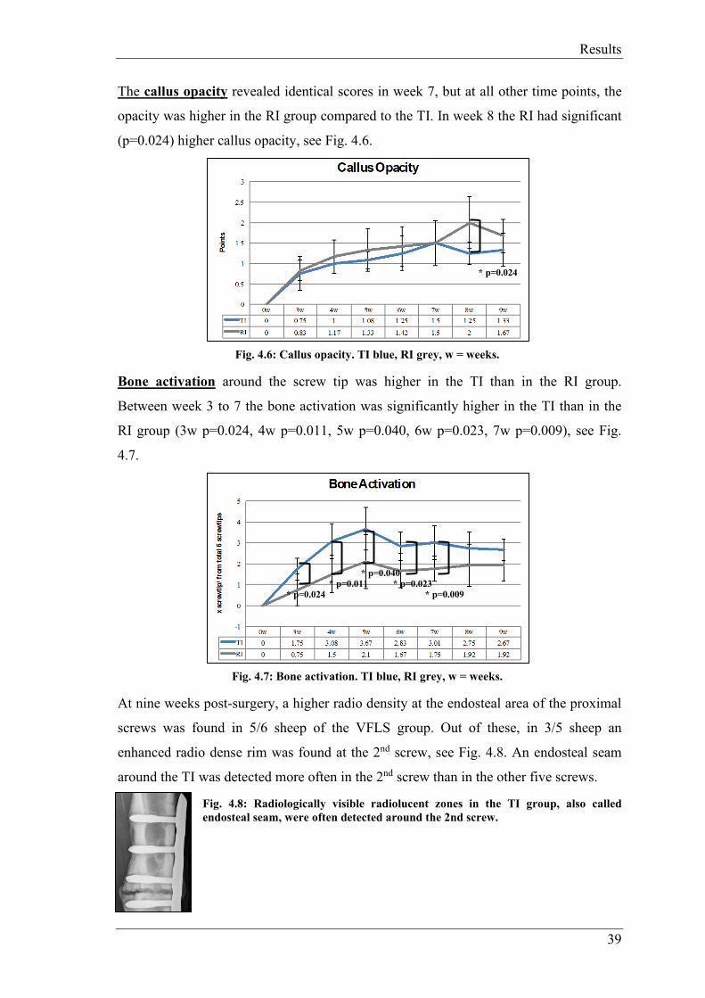
Results
39
The callus opacity revealed identical scores in week 7, but at all other time points, the
opacity was higher in the RI group compared to the TI. In week 8 the RI had significant
(p=0.024) higher callus opacity, see Fig. 4.6.
Fig. 4.6: Callus opacity. TI blue, RI grey, w = weeks.
Bone activation around the screw tip was higher in the TI than in the RI group.
Between week 3 to 7 the bone activation was significantly higher in the TI than in the
RI group (3w p=0.024, 4w p=0.011, 5w p=0.040, 6w p=0.023, 7w p=0.009), see Fig.
4.7.
Fig. 4.7: Bone activation. TI blue, RI grey, w = weeks.
At nine weeks post-surgery, a higher radio density at the endosteal area of the proximal
screws was found in 5/6 sheep of the VFLS group. Out of these, in 3/5 sheep an
enhanced radio dense rim was found at the 2nd screw, see Fig. 4.8. An endosteal seam
around the TI was detected more often in the 2nd screw than in the other five screws.
Fig. 4.8: Radiologically visible radiolucent zones in the TI group, also called endosteal seam, were often detected around the 2nd screw.
* p=0.024
* p=0.011 * p=0.024
* p=0.040 * p=0.023
* p=0.009

Results
40
4.5.1.2 Quantitative radiologic evaluation
The quantitative radiologic evaluation was performed using OsiriX to measure the
callus area at the fracture gap in all three projections (anteroposterior (ap, 0°),
anterolateral (275°) and posterolateral (265°)).
In total, in the mean measurements of all three projections the TI showed more callus
area compared to the RI group. Detailed results see appendix, page 72, Tab. 7.16 – 7.20.
Fig. 4.9: Mean callus area in all three projections. The TI group (blue) showed more callus area compared to the RI group (grey), w = weeks.
At week 3 and 4 post-surgery, the RI group had slightly more callus area in total (TI
1.39-2.95 cm2; RI 1.48-3.03 cm2). In both groups periosteal callus increased
continuously until week 8, at which the peak callus area was detected. The callus area in
week 9 was lower than in week 8 for both groups. There were no significant differences
at any time point.
Fig. 4.10: Mean callus in anteroposterior, anterolateral and posterolateral projection. TI blue, RI grey, w = weeks.
On the anteroposterior and the anterolateral projection a bigger callus area was
measured in the TI group, except in week 3. However, in week 3 the RI (0.237 cm2)
showed more callus compared to the TI group (0.209 cm2). In the posterolateral
projection, the callus area of RI was more pronounced until week 6, at all later time
points the callus areas were almost the same size.

Results
41
4.5.2 Micro-CT
The µCT allowed three dimensional evaluation of bone volume and density as well as
callus volume and density. Additionally, the polar moment of inertia (pMOI) was
measured as quantitative information about the distribution of the callus around the
bone axis. In all 12 tibiae, µCT measurements were performed between the proximal k-
wire insertion and the distal k-wire insertion measuring the total callus and bone area
(not only the fracture gap area).
Fig. 4.11: Bone volume and bone density boxplots (source: Micro-CT report Scanco Medical)
Fig. 4.12: Callus volume and callus density boxplots (source: Micro-CT report Scanco Medical)
No significant differences between groups could be found for bone volume and density
(p=0.42, p=0.069). TI (23.8 ccm ± 2.8 ccm) showed slightly higher values for bone
volume compared to RI (22.8 ccm ± 1.0 ccm). Bone density was slightly higher in RI
(1225 mgHA/ccm ± 13 mgHA/ccm) compared to TI (1213 mgHA/ccm ± 8
mgHA/ccm). There was a significantly larger amount of callus (p=0.004) in TI samples
implanted with TI (17.8 ccm ± 5.4 ccm) with respect to those implanted with RI (9.3
ccm ± 1.7 ccm). However, this tissue featured a significant lower density (p=0.0024) in
the TI group (680 mgHA/ccm ± 18 mgHA/ccm) compared to the RI group (739
mgHA/ccm ± 31 mgHA/ccm).
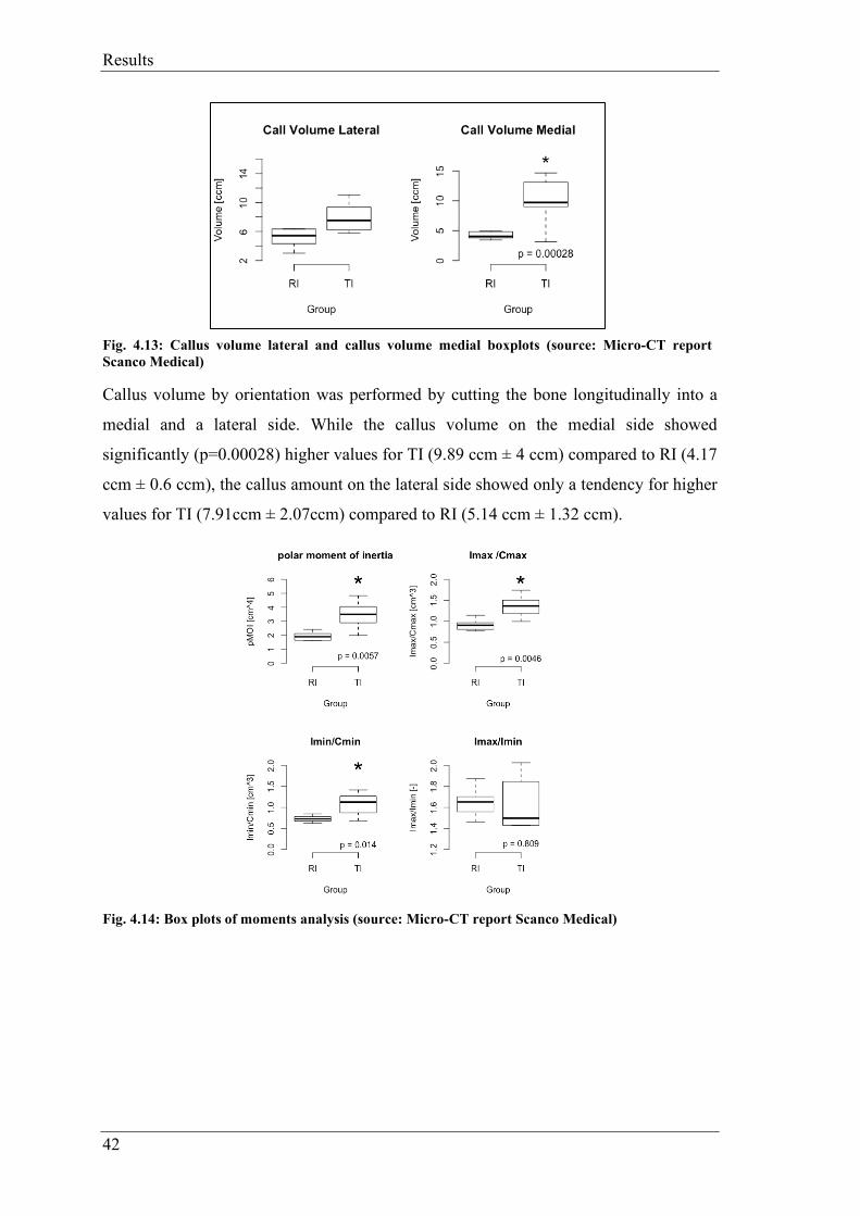
Results
42
Fig. 4.13: Callus volume lateral and callus volume medial boxplots (source: Micro-CT report Scanco Medical)
Callus volume by orientation was performed by cutting the bone longitudinally into a
medial and a lateral side. While the callus volume on the medial side showed
significantly (p=0.00028) higher values for TI (9.89 ccm ± 4 ccm) compared to RI (4.17
ccm ± 0.6 ccm), the callus amount on the lateral side showed only a tendency for higher
values for TI (7.91ccm ± 2.07ccm) compared to RI (5.14 ccm ± 1.32 ccm).
Fig. 4.14: Box plots of moments analysis (source: Micro-CT report Scanco Medical)

Results
43
Fig. 4.15: Spatial analysis of moments (source: Micro-CT report Scanco Medical)
The polar moment of inertia was significantly (p=0.0057) higher in TI (3.46 cm4 ± 1.02
cm4) compared to RI (1.93 cm4 ± 0.3 cm4). Also the Imax/Cmax was significantly
(p=0.0046) higher in TI (1.36 cm3± 0.27 cm3) compared to the RI group (0.92 cm3 ±
0.13 cm3). Furthermore, TI (1.08 cm3 ± 0.28 cm3) showed significantly (p=0.014)
higher values in Imin/Cmin compared to RI (0.73 cm3 ± 0.08 cm3), but no differences in
Imax/Imin (TI: 1.62 ± 0.25; RI: 1.65 ± 0.14).
The profiles of the moments of inertia illustrate the spatial distribution of callus tissue
with respect to the relative bone axis. The Pos X = 60 is the middle of the fracture gap.
There was a clear difference in polar moment of inertia at all cross-sections between 40
mm proximal and distal to the fracture gap (TI in red and RI groups in black). For
example, at midshaft (Pos X=60), pMOI was >200% higher in TI compared to RI
(p<0.05), IMAX/CMAX ~160%, IMIN/CMIN ~100% respectively.
Gap sub-analysis ROI
Additionally, an analysis of the gap including the 3rd and 4th screw hole (ROI) was
performed (see Fig. 4.16 and Fig. 4.17).

Results
44
Fig. 4.16: Gap sub-analysis ROI (source: Micro-CT report Scanco Medical)
Limiting the investigation to the smaller ROI (callus volume around the gap divided
into medial and lateral part) showed that:
Fig. 4.17: Gap sub-analysis by orientation (source: Micro-CT Scanco Medical)
In total, the callus volume on the lateral side was higher TI (4.79 ccm ± 1.29 ccm)
compared to RI (3.67 ccm ± 0.82 ccm). On the medial side TI also revealed more callus
(4.7 ccm ± 1.19 ccm) compared to RI (2.48 ccm ± 0.32 ccm).
TI featured a significantly larger amount of callus on the medial side (p=0, TI:med-
RI:med) and on the lateral side (p<0.0001, TI:lat-RI:lat) with respect to RI.
There was a significant (p<0.0001, RI:med-RI:lat) difference in the amount of medial
callus compared to the lateral callus in RI.
TI featured on the medial side a significantly (p=0.0001, TI:med-RI:lat) larger amount
of callus compared to RI on the lateral side. The medial callus amount of TI was
significantly (p=0, RI:med-TI:lat) larger compared to the lateral amount of RI.
There is no difference between the amount of callus on the medial and on the lateral
side in TI (TI:med-TI:lat).
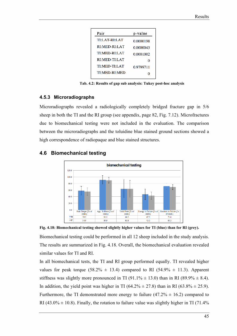
Results
45
Tab. 4.2: Results of gap sub analysis: Tukey post-hoc analysis
4.5.3 Microradiographs
Microradiographs revealed a radiologically completely bridged fracture gap in 5/6
sheep in both the TI and the RI group (see appendix, page 82, Fig. 7.12). Microfractures
due to biomechanical testing were not included in the evaluation. The comparison
between the microradiographs and the toluidine blue stained ground sections showed a
high correspondence of radiopaque and blue stained structures.
4.6 Biomechanical testing
Fig. 4.18: Biomechanical testing showed slightly higher values for TI (blue) than for RI (grey).
Biomechanical testing could be performed in all 12 sheep included in the study analysis.
The results are summarized in Fig. 4.18. Overall, the biomechanical evaluation revealed
similar values for TI and RI.
In all biomechanical tests, the TI and RI group performed equally. TI revealed higher
values for peak torque (58.2% ± 13.4) compared to RI (54.9% ± 11.3). Apparent
stiffness was slightly more pronounced in TI (91.1% ± 13.0) than in RI (89.9% ± 8.4).
In addition, the yield point was higher in TI (64.2% ± 27.8) than in RI (63.8% ± 25.9).
Furthermore, the TI demonstrated more energy to failure (47.2% ± 16.2) compared to
RI (43.0% ± 10.8). Finally, the rotation to failure value was slightly higher in TI (71.4%

Results
46
± 8.7) than in RI (69.3% ± 7.9). However, statistically significant values were not found
in any of the five tests, see detailed results in appendix, page 73, Tab. 7.21.
4.7 Histological evaluation
4.7.1 Histomorphometry
Twelve toluidine blue stained histological ground sections of two implant types (TI=6
and RI=6) were histomorphometrically evaluated using total and sectoral section
analysis. For histological slides see appendix, page 83, Fig. 7.13.
For each sample, percentages of old bone, new bone, as well as non-bone structures
(non-bone containing tissue) were measured for the total section, while for the sectoral
evaluation, percentages of new bone formation (callus) in the endosteal, cis and trans
area were evaluated. Overall, histomorphometrical measurements revealed a good
healing of the defect area for both, TI and RI.
4.7.1.1 Total section
Results for histomorphometrical evaluation of the total section are shown in appendix,
page 73, Tab. 7.22 and page 83, Fig. 7.14.
Fig. 4.19: In the TI group more old bone was resorbed (3.02%) and therefore more new bone built (3.45%) than in the RI group. Non-bone tissue was almost equal with 0.43% difference.
Overall, no significant differences were found between TI and RI for any of the values
for the total section analysis. Nevertheless, the percentage of old bone matrix was
slightly lower in the TI (26.86% ± 2.77) than in the RI group (30.28% ± 3.11), while
slightly more new bone tissue was detected in the TI (34.02% ± 2.94) than in the RI
group (30.61% ± 3.18). Non-bone tissue showed equal results in both groups, TI
(39.12% ± 3.64) and RI (39.12% ± 3.22).

Results
47
4.7.1.2 Sectoral section
Results for histomorphometrical evaluation of the sectoral section are shown in
appendix, page 73, Tab. 7.23 and page 84, Fig. 7.15.
Fig. 4.20: There was a significant difference (p=0.012) in the endosteal callus amount. The TI group built 12.39 % more endosteal callus.
Significant differences were found in the sectoral evaluation for endosteal callus, with
significantly (p= 0.012) higher values in the TI (43.69%) than in the RI group (31.3%).
Slightly higher values for callus formation were found in the RI group at the cis cortex
(15.67%) and at the trans cortex (53.04%) compared to the TI group (12.42% and
43.9%, respectively).
4.7.2 Thin section evaluation (cis/trans): quantitative and semiquantitative analysis of local tissue effects (ISO)
Assessment of biocompatibility parameters, bone remodeling and additional
observations (traumatic necrosis and foreign debris) of TI and RI was performed
separately in two different sections (cis and trans cortex). In the screw hole area
(cortices including bone marrow cavity) only biocompatibility and additional
observations were evaluated. In the defect area only bone remodeling was evaluated.
In total, 72 Hematoxylin-Eosin, toluidine blue and von Kossa stained histological
sections of two implant types (TI and RI) were evaluated according to ISO-Norm
10993-6:2016(E). The evaluation was performed by two independent observers.
Individual scoring results for TI and RI are illustrated in appendix, page 74, Tab. 7.25
Anhang for the results at the cis cortex and in appendix, page 75, Tab. 7.26 for the trans
cortex.
Biocompatibility (screw hole)
Under the conditions of this study, TI was considered to demonstrate a minimal reaction
(ØTI - ØRI = 2.0) to the tissue at the trans cortex compared to RI. At the cis cortex
*p = 0.012

Results
48
(where the LCP was placed), the TI demonstrated a slight reaction (ØTI - ØRI = 8.2)
compared to RI indicating normal biodegradation and tissue remodeling.
Overall, at both cortices and in the bone marrow cavity, no polymorphonuclear cells, no
eosinophils and no necrosis/osteolysis were observed in any of the samples of both
groups, TI and RI.
Trans (lateral) side including bone marrow cavity:
No lymphocytes and plasma cells were found in both groups, TI and RI. Macrophages could be detected in all 6/6 TI samples and in 1/6 RI samples. They were found in the TI group in 4/6 animals in a low (score 2) and in 2/6 animals in a minimal amount (score 1). In the RI group, in one sample (84.01) a low amount (score 2) was detected. Giant cells were found in the TI group in 1/6 samples in a low amount (score 2) and in 2/6 samples in a minimal amount (score 1). In the RI group, giant cells were detected in 1/6 samples in a minimal amount (score 1). Neovascularization was found in 5/6 animals of TI and in 1/6 animals of the RI group with minimal capillary proliferation (score 1). Minimal amounts of fibrosis (score 1) were detected in 5/6 animals of the TI and in 1/6 animals of the RI group. No fatty infiltration (cortex only) was found in any of the samples of both groups. See example in appendix, page 87, Fig. 7.25.
Cis (medial) side including bone marrow cavity:
No plasma cells were found in either of both groups. Lymphocytes were detected in a minimal amount (score 1) in 2/6 animals of the TI group, whereas in the RI, no lymphocytes were found. Macrophages could be detected in all animals of both groups, TI and RI. They were found in a moderate amount (score 3) in 3/6 animals of the TI group and in 3/6 animals in a low amount (score 2). In the RI group, the amount of macrophages was low (score 2) in 3/6 animals and in 3/6 animals it was minimal (score1). Giant cells were spotted in the TI in all 6/6 animals, whereas in the RI group no giant cells were detected. Neovascularization and fibrosis was found only in a minimal amount in 1/6 animals of the RI, while in the TI group they were found in all 6/6 animals either in a minimal (score 1, 4/6 animals) or slight amount (score 2, 2/6). Low amounts of fatty infiltrates (cortex only) were found in 5/6 animals of TI group, see appendix, page 88, Fig. 7.26.
Additional observations (screw hole)
No traumatic necrosis due to the surgical procedure was detected in either group.
Metallosis was found in 5/6 TI samples and 6/6 RI samples at the cis cortex as dark brown and black stained conglomerates (see appendix, page 87, Fig. 7.24). At the trans

Results
49
cortex, metallosis was only found in 3/6 RI samples. Cell associated (macrophages, giant cells) and free foreign material was detected in all evaluated TI samples (see appendix, page 86, Fig. 7.20-7.23). In the cis cortex sections, it was found in the cortex and in the bone marrow area, while in the trans cortex sections it was mostly found in the bone marrow area of the sections, described as finely stippled material.
Bone remodeling (defect area)
Trans (lateral) side including only defect area:
In the TI, osteoclasts were detected in 4/6 animals in a rare amount (score 1) and in 2/6
animals in a moderate amount (score 2), whereas all animals from the RI group showed
a rare amount (score 1). Bone activity was static in 5/6 animals and in formation in 1/6
animals (84.02) in the TI group. The same level of resorption and formation (score
static) was detected in 4/6 animals and only formation was seen in 2/6 animals in the RI
group. 4/6 samples of TI were almost united (score 4, 76-100%), 1/6 samples was
moderately united (score 3, 51-75%), 1/6 samples slightly united (score 1, <15%)
(84.06). In the RI group, 4/6 samples showed a defect unity of over 76% (score 4), 1/6
samples a moderate unity (score 3, 51-75%) and 1/6 sample had no unity at all (score 0,
0%) (84.03). Sheep 84.03 and 84.06 showed a delayed-union.
Cis (medial) side including only defect area:
In the TI, no osteoclasts (score 0) were seen in 1/6 animals (84.09), in 3/6 animals a rare
amount (score 1) was spotted and in 2/6 animals a moderate amount (score 2), whereas
in the RI group osteoclasts were found in low numbers (score 1) in all animals. All
samples from the TI showed a static bone activity, whereas in the RI in 4/6 samples a
static bone activity was evaluated and in 2/6 samples in formation. The defect was in in
all samples almost united or united (score 4, 76-100% defect unity).
4.7.3 Fluorescence
Fluorescence dyes are markers for bone activation (including bone activation, bone
development and bone resorption) in the next 48-72 hours after injection as it binds to
the calcium. See appendix page 84 and 85, Fig. 7.16- Fig. 7.19.

Results
50
Fig. 4.21: In the different fluorescence sections there was always a slight difference between the two groups.
Quantitative evaluation at nine weeks demonstrated a dominance of calcein green
(application three weeks postoperatively) in TI (4.55 ± 1.72) compared to RI (3.69 ±
2.18). Xylenol orange, which was injected six weeks postoperatively, was detected in a
higher amount in RI (2.1 ± 1.46) than in TI (1.38 ± 1.11). Finally, oxytetracycline
depositions (given 48 to 72 hours before sacrifice) were more prominent in TI (5.62 ±
3.08) than in RI (3.79 ± 0.7). Detailed results see appendix, page 73, Tab. 7.24.
Fig. 4.22: Overall, the TI showed more fluorescence depositions compared to the RI.
The semiquantitative evaluation performed by two independent observers revealed an
almost equal deposition of calcein green for TI and RI (TI: C7, M10, T12; RI: C7, M8,
T11). Xylenol orange sections of TI showed more depositions at the cis cortex and
intramedullary than at the trans cortex (TI: C10, M14, T12; RI: C8, M10, T12). The
oxytetracycline colored slides of TI showed more fluorescence deposition in all three
parts (TI: C13, M14, T12; RI: C8, M12, T8).

Results
51
4.7.4 Lymph node analysis
In total, 48 lymph nodes (lnn. inguinales and poplitei treated and non-treated limb) of
12 animals were evaluated (see Fig. 4.23). Individual scoring results for TI and RI are
illustrated in appendix, page 76, Tab. 7.27.
Overall, no test item related findings were detected during the lymph nodes evaluation.
Minimal structure changes (score 1), characterized by slight activation of the
germinative zones were found in the popliteal and inguinal lymph nodes in both groups,
TI and RI. These changes were found in both limbs, treated and non-treated. In addition,
only a minimal amount (score 1) of nonlocal cells (inflammatory/hypersensitivity cells)
were detected in the popliteal and inguinal lymph nodes in similar amounts in both
groups. Comparable scores were found for the treated and non-treated limbs.
In almost all lymph nodes of the RI and in all of the TI group, different amounts of
activated foamy (epithelioid-like) macrophages were detected mostly along lymph
vessels. This finding indicates non test-item related systemic reaction of unspecified
origin. In 11/12 animals of both groups, no intra or extracellular foreign material could
be found in either of the lymph nodes (lnn inguinales or poplitei). Only in one animal of
the TI group (84.02), unidentified brownish-beige small dotlike particles were observed
in the cytoplasm of foamy (epithelioid-like) macrophage aggregates detected in the right
inguinal lymph node. This intracellular material was not polarizing under the
microscope, and therefore could not be specified, neither as wear particles nor sleeve
material (see appendix, page 88, Fig. 7.27). The Ziehl-Neelsen staining for acidophilic
bacteria was negative.
Fig. 4.23: Results of histological scoring of 48 lymph nodes of 12 animals. TI treated leg blue, TI non-treated leg light blue; RI treated leg grey, RI non-treated leg light-grey.

Discussion
52
5 Discussion
In this study, the VFLS has been investigated for its boosting effect on bone fracture
healing through using the variable fixation technology with a suitable animal model.
Perren et al. found out, that biomechanical stimuli are the inductors in fracture
healing20. By using variable fixation technology, it should be possible to optimize
biomechanical stimuli respectively strain for each phase of fracture healing. Liu et al.
confirmed, that the bone healing process is driven by gradual changes in the strain and
that for each of the four healing phases the ideal strain levels are slightly different17.
The VFLS showed in this study that it has the potential to implement the theory and the
present research.
Overall, the surgical procedure was optimized using cadaver surgeries and pre-operative
radiographs of the sheep tibiae to measure its diameter. Only large sheep with long and
straight tibiae of a wide diameter were selected for this study. A wide diameter was
important as the screws for human medicine are longer (32 mm and 34 mm). The
surgeries could be performed precisely and reproducibly with custom-designed drill
guides. The surgery procedure was similar to a previous MSRU study51 performed by
the same surgeon.
A standardized animal model using a transverse tibia osteotomy in sheep with a 3 mm
gap was needed to compare the results to those from previous studies testing new screw
designs 50,51,55. Sheep used in this study were healthy animals and did not have a
predisposition for non- or delayed unions. The differences between VFLS and LS might
be more evident than highlighted in this study. If only patients with a predisposition for
fracture healing failures were selected for the study, the result may differ more between
VFLS and LS. In the LS group less callus formation, whereas in the VFLS group a
union would be expected.
Furthermore, the major differences in veterinary and human medicine are the
compliances and the patient behaviour. Animals use their operated limbs right after the
surgery with full weight bearing, whereas humans control their weight bearing and use
crutches to protect their operated limb. To prevent a full weight bearing, sheep were
kept in a suspension system for the first 3 weeks. Additionally, the operated limb was
casted immediately after surgery to reduce torsional and sheer forces, as translational

Discussion
53
sheer movement can lead to delayed or non-union34. However the main reason for
casting was to avoid re-fracturing.
Regarding the surgery, the insertion of the VFLS was possible in all eight sheep. None
of the VFLS failed after successful implantation, got loosened or elicited a problem
during implant removal at sacrifice after 9 weeks. During the insertion procedure of the
screws, the sleeve was often displaced and in 7/48 screws it broke one to three times.
Due to that, the VFLS were inserted by hand. In some cases, the screw hole was
predrilled with a VFLS without a sleeve to enlarge the hole and prevent sleeve
breakage. In cadaver tests performed by our surgeon, with human and sheep tibiae, no
sleeve breakage or sleeve displacement occurred while using the drilling machine. The
reason for that could be that by using the drilling machine, the cis cortex had no time to
contract. The sleeve often broke in the 4th screw. Anatomically, the tibia has a smaller
diameter in the region where the 4th screw was implanted than in the remaining part.
Due to that, the sleeve could have touched the trans cortex during insertion, slipped and
then broke.
One sheep (84.04) with the 4th screw in direct connection to the gap was excluded,
because the fracture healing could have been boosted by this 4th screw, in order of more
bone activation and remodeling.
All evaluation methods for this study could be applied precisely, reproducibly and
successfully to evaluate bone healing by using the VFLS.
At the day of sacrifice, the RI screw showed a higher value in removal torque compared
to the TI screw. All screws of both groups were locked. The thread of the RI screw was
in contact with the cis and trans cortex, while threads of the TI screw were only fixed in
the trans cortex. In contrast to the Far Locking Screw system the VFLS did not have a
problem with removal at the cis cortex. In preclinical tests with the FLS the
osseointegration in the cis cortex had been far advanced, such that difficulties with
threads from the trans cortex occurred during removal. Thus, the design of the final
screw required adaptation such that the lag screw part was widened and even shows
thread-like structures which allow for removal without complication. With the VFLS
the polymer seems to keep the distance. That could be the reason why the removal
torque was lower in the TI without negative consequences for the locking system. It

Discussion
54
may be concluded that the TI is easier to remove than the RI at least after 9 weeks. This
is a very relevant point as, for example, the DLS has been recalled by the FDA in 2015
due to pin breakage during removal52.
Radiographically, the two reviewers were able to agree on the same mean score for
every radiograph (semiquantitative radiographic evaluation). It was debatable, if the
callus at the trans cortex of the VFLS was considered as irritation callus, as there was
often a callus around the screw tip. Irritation callus might be the consequence of micro-
instability16, which in patients with predisposition to bone healing failure could be a
problem. On the other hand, it could also stimulate bone healing in those people, where
bone healing activity parameters are a major problem. That means, TI is able to activate
the bone tissue, eliciting a reaction far from the fracture gap as well as the whole organ
itself.
Exceeding callus at the cortex is not always desired and does not always mean that the
bone heals properly. In the early time points between three and four weeks after surgery
both groups had almost similar scores. The reason for that could be, that the sleeve
resorption starts around that time and at earlier time points the VFLS acts like the LS.
As for phase I of fracture healing the LS gives the reference point. Liu et al. found out
that the ideal strain levels are slightly different in all four phases of bone healing17. The
VFLS takes the different strain conditions into account to promote fracture healing.
After four weeks, the TI group showed less periosteal callus compared to the RI group.
Taking the histomorphometry results into account, it could be shown that the TI
developed significantly more endosteal callus compared to the RI group. This increased
endosteal callus formation over time provides higher stability right within the
longitudinal axis of the bone. Therefore, callus formation at the trans cortex was less
promoted, since the endosteal callus already ensured sufficient stability.
Furthermore, small fissures in the cortical part of the fragment at the trans cortex were
often seen in the radiographs already immediately postoperatively. Osteotomies often
cause little cracks at the trans cortex. Additionally, as mentioned before, the sheep tibia
is very brittle and the screws (designed for human size) were at the upper limit with
their diameter. Less fracture lines were detected in TI, maybe because the screw was
inserted more slowly by hand and sometimes the surgeon decided to predrill with
another screw.

Discussion
55
Moreover, radiolucent zones at the cis cortex of the TI screws, where the sleeve was
resorbed, were detected. However, this may be expected since resorption of the polymer
was ongoing and thus, radioopacity of this area is expected to be increased. The reason
could also be due to the micromotion respectively stimulation of the whole bone besides
sleeve resorption (more space between bone and screw after resorption). However, in
this case resorption would be expected over the entire length of fixation including the
trans cortical part of the screws. Also, a more pronounced stimulation of the periost at
the screw tip would then be expected. Since this was not the case and the transcortical
part of the screws did not show increased radiolucency, it is safe to assume that
resorption of the polymer was the reason for this radiological appearance.
In the quantitative radiographic evaluation using the OsiriX program, more callus area
in total was detected for TI compared to RI. The TI group showed more callus in all
three projections except at the beginning in the posterolateral projection. But both
groups were almost equal in the early time points (until four weeks). As mentioned
before, this indicates the same behavior of the two screws at earlier time points, when
the sleeve of the VFLS was still fully present.
Furthermore, the TI group showed a callus, which was longer in size but less dense
compared to the callus of the RI group. This was also confirmed in µCT, indicating that
the TI was able to activate the whole bone.
In the µCT, a significantly higher callus volume in TI (17.8 ccm, p=0.004) compared to
RI (9.31 ccm) and a higher bone volume was detected for the TI compared to the RI
group. At the whole medial longitudinal part of the tibiae, TI built significantly (9.89
ccm, p=0.00028) more callus compared to RI (4.17 ccm). This could also be found at
the lateral part of the tibia, but without significant differences (TI: 7.91 ccm; RI = 5.14
ccm).
In the ROI (gap including 3rd and 4th screw hole), TI showed more callus on the medial
(4.7 ccm) and lateral side (4.79 ccm) in comparison to RI (medial 2.48 ccm; lateral 3.67
ccm). Comparing the µCT results with the histomorphometric and the semiquantitative
radiographic evaluation (TI showed less cis and trans callus), results do not match at
first sight. But taking into account that the histomorphometry and the semiquantitative
radiographic evaluation are only a 2D view and involve only the medial and lateral

Discussion
56
sides, it could be, that RI showed a bigger callus area when only evaluating medial and
lateral sides without the anterior and posterior sides.
At the posterior side, which is only included in the µCT, more motion respectively a
higher amount of callus can be caused due to muscle contraction and a physiologically
higher load on the posterior limb.
In the µCT, the bone volume in the ROI of the TI group was higher compared to the RI
group. As shown in the histological evaluation, the TI group had less old bone and more
new bone formation. TI showed more callus and bone volume compared to RI in the µ-
CT. On the one hand, the threshold plays an important role in the µCT evaluation. It
depends, where the threshold was set to recognize old bone and new bone respectively
callus. On the other hand, as mentioned before, the radiographic evaluation is a 2D view
and endosteal callus or bone formation in the posterior and anterior projection cannot be
detected. However, the fact that TI showed less old but more new bone formation could
also mean that due to the dynamization of the bone healing process more active
remodeling at the osteotomy side had taken place. These results are corroborated with
the results of intravital fluorescence staining, where the VFLS showed higher values.
In the semiquantiative radiographic and µCT evaluation, callus and bone density of the
whole tibia were significantly higher in RI compared to TI. Due to an activated
remodeling process where in the TI group old bone was rebuilt to new bone, the bone
density was lower due to a smaller amount of old bone with high density compared to
the RI group. The TI group showed significantly more callus volume in the µCT. As the
results of the mechanical tests did not detect significant differences between groups in
any of the investigated variables. It could be concluded that the development of the
large amount of callus in the TI group was still in the physiological mechanical property
range leading to successful gap closure.
Furthermore, the callus area of the TI group was much longer compared to the RI group.
Another reason to note could be that the RI group has formed a more compact callus,
which was smaller and already receding.
The higher polar moment of inertia in all sections of the TI group, indicated more callus
around the bone axis which was well distributed proximal and distal to the fracture gap.
This is another indication that the entire bone has been activated. Furthermore, the
analysis of principal axes showed a higher Imax/Cmax and Imin/Cmin around the
segmental defect in the TI group compared to the RI group. This could suggest that
torsional stiffness and breaking strength were higher in the TI group.

Discussion
57
Biomechanically, the RI and TI group showed almost equal results with slightly higher
values for TI. It could be, that the higher amount of endosteal callus in the TI group had
an important effect on fracture stabilization. It has been proven that an unstable fixation
could cause a larger amount of callus (“irritation callus”)16 and afterwards led to
pseudoarthrosis33. But in our study, with no significant differences in the mechanical
properties, it seems that with the VFLS more callus volume can be built without
compromising the tissue resistance (normal callus). The RI group had a denser callus
and more concentrated at the trans cortical, resp. lateral sides compared to the TI, which
showed a more even distribution between trans and cis cortex. In addition, endosteal
callus is usually less dense compared to the cortical callus which is more like a shell and
resists better to torsional and shear forces. Nevertheless, the combination of the
endosteal and more evenly distributed callus resulted in comparable numbers for the
biomechanical tests. For patients with predispositions for fracture failure, a more even
distributed and endosteal callus may be favourable meaning more chances to gain
complete fracture healing. Histologically, due to the micromotion of the VFLS group,
more old bone was resorbed and more new bone was built (total section
histomorphometry). When thinking of the human patients predisposed to delayed-union
and non-union, such an active process is welcome. In the sectoral histomorphometrical
analysis, the TI group showed significantly more endosteal callus (p=0.012; TI 43.69%)
compared to the RI group (31.3%). The reason for that could be, that the endosteal
callus was built to stabilize the fracture during the micromotion.
Compared to the study of Richter et al. testing the DLS, our RI group performed much
better compared to the RI group of Richter et al., even under the same conditions as the
control group of this study51. The reason for this could not be explained except the fact
that the mechanical tests were not performed by the same person and that the Instron
machine may have been adapted in the mean time (ca. 6 years in between tests).
Nevertheless, since results were compared to internal controls the results are validated
within the specimens of the same animals and can be accepted.
Overall, under these experimental study conditions, the histological findings
demonstrated a good biocompatibility of the VFLS (following test guideline: ISO
10993-6: 2016), in comparison to the RI screw (cis cortex ØTI - ØRI = 8.2 and trans
cortex ØTI - ØRI = 2.0). The TI did not induce significant tissue effects. No acute or
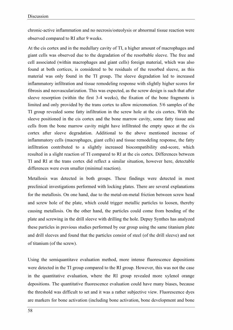
Discussion
58
chronic-active inflammation and no necrosis/osteolysis or abnormal tissue reaction were
observed compared to RI after 9 weeks.
At the cis cortex and in the medullary cavity of TI, a higher amount of macrophages and giant cells was observed due to the degradation of the resorbable sleeve. The free and cell associated (within macrophages and giant cells) foreign material, which was also found at both cortices, is considered to be residuals of the resorbed sleeve, as this material was only found in the TI group. The sleeve degradation led to increased inflammatory infiltration and tissue remodeling response with slightly higher scores for fibrosis and neovascularization. This was expected, as the screw design is such that after sleeve resorption (within the first 3-4 weeks), the fixation of the bone fragments is limited and only provided by the trans cortex to allow micromotion. 5/6 samples of the TI group revealed some fatty infiltration in the screw hole at the cis cortex. With the sleeve positioned in the cis cortex and the bone marrow cavity, some fatty tissue and cells from the bone marrow cavity might have infiltrated the empty space at the cis cortex after sleeve degradation. Additional to the above mentioned increase of inflammatory cells (macrophages, giant cells) and tissue remodeling response, the fatty infiltration contributed to a slightly increased biocompatibility end-score, which resulted in a slight reaction of TI compared to RI at the cis cortex. Differences between TI and RI at the trans cortex did reflect a similar situation, however here, detectable differences were even smaller (minimal reaction).
Metallosis was detected in both groups. These findings were detected in most
preclinical investigations performed with locking plates. There are several explanations
for the metallosis. On one hand, due to the metal-on-metal friction between screw head
and screw hole of the plate, which could trigger metallic particles to loosen, thereby
causing metallosis. On the other hand, the particles could come from bending of the
plate and screwing in the drill sleeve with drilling the hole. Depuy Synthes has analyzed
these particles in previous studies performed by our group using the same titanium plate
and drill sleeves and found that the particles consist of steel (of the drill sleeve) and not
of titanium (of the screw).
Using the semiquantitave evaluation method, more intense fluorescence depositions
were detected in the TI group compared to the RI group. However, this was not the case
in the quantitative evaluation, where the RI group revealed more xylenol orange
depositions. The quantitative fluorescence evaluation could have many biases, because
the threshold was difficult to set and it was a rather subjective view. Fluorescence dyes
are markers for bone activation (including bone activation, bone development and bone

Discussion
59
resorption) within 48 hours after injection binding to the calcium and being embedded
in newly formed bone62. Due to the micromotion and the increased resorption of old
bone and new bone formation it is clear that in the TI group the bone is more activated
and therefore accumulates more fluorescence.
Due to the sleeve resorption, lymph nodes could have been stimulated in the TI group,
leading to more structure changes compared to the RI group.
Whereas, the amount of nonlocal cells found in lymph nodes was similar for both, RI
and TI group, which indicates a non test-item related system reaction. These findings
could also be induced by stress-related immunosuppression (e.g. surgical intervention)
and increased sensibility to bacterial infection or parasitic infestation. The appearance
of activated foamy (epithelioid-like) macrophages mostly along lymph vessels was
detected in both groups, TI and RI. They were interpreted also as non test-item related
findings of unspecified origin. No clinical abnormalities or other abnormal findings
were observed in any of the twelve operated sheep, so that these findings can be
considered having no impact on the study outcome.

Discussion
60
5.1 Conclusion
In conclusion, the results of this study confirm that the variable fixation technology
using the Variable Fixation Locking Screw has some boosting effects on bone fracture
healing. The results of this study also demonstrate that the VFLS is a biocompatible and
safe medical device as good as the commercial titanium Locking Screw (RI), as none of
the sheep implanted with VFLS showed any signs of abnormal systemic response. The
sleeve degradation was as expected.
A new medical device is urgently needed, as population numbers are rising rapidly7,8
and the expensive costs of fracture healing failure are increasing enormously6.
Since today, the VFLS would be the first screw on the market, which has a variable
strain magnitude and not a constant strain. The activation of the entire bone as an organ,
suggest that the VFLS has the potential to increase the success rate of biological
osteosynthesis in the target group (older people, predisposed for delayed- and non-
union).
However, further clinical studies in human medicine are required to clarify the outcome
of VFLS in human patients with predispositions for bone healing failure.

References
61
6 References
1. Wang Z, Bhattacharyya T: Trends of non-union and prescriptions for non-steroidal anti-inflammatory drugs in the United States, 1993-2012. Acta Orthop 86:632-637, 2015.
2. Papakostidis C, Grotz MR, Papadokostakis G, et al: Femoral biologic plate fixation. Clin Orthop Relat Res 450:193-202, 2006.
3. Jayakumar P, Jupiter JB: Non-union in forearm fractures. Acta Chir Orthop Traumatol Cech 81:22-32, 2014.
4. Wolinsky PR, McCarty E, Shyr Y, et al: Reamed intramedullary nailing of the femur: 551 cases. J Trauma 46:392-399, 1999.
5. Peter V. Giannoudis RA: Management of long-bone non-unions. Elsevier Injury, Int J Care Injured 38:1-2, 2007.
6. Versicherung SSU: Sammelstelle für die Statistik der Unfallversicherung UVG. 2017.
7. Singer BR, McLauchlan GJ, Robinson CM, et al: Epidemiology of fractures in 15,000 adults: the influence of age and gender. J Bone Joint Surg Br 80:243-248, 1998.
8. Affairs UNDoEaS: Wold Population Ageing 2013. 2013. 9. Klonoff DC: The increasing incidence of diabetes in the 21st century. J Diabetes Sci
Technol 3:1-2, 2009. 10. Spanheimer RG, Umpierrez GE, Stumpf V: Decreased collagen production in
diabetic rats. Diabetes 37:371-376, 1988. 11. centre WM: Obesity and overweight. 2015. 12. Copuroglu C, Calori GM, Giannoudis PV: Fracture non-union: who is at risk?
Injury 44:1379-1382, 2013. 13. Lujan TJ, Henderson CE, Madey SM, et al: Locked plating of distal femur fractures
leads to inconsistent and asymmetric callus formation. J Orthop Trauma 24:156-162, 2010.
14. Schell H, Thompson MS, Bail HJ, et al: Mechanical induction of critically delayed bone healing in sheep: radiological and biomechanical results. J Biomech 41:3066-3072, 2008.
15. Rodriguez-Merchan EC, Forriol F: Nonunion: general principles and experimental data. Clin Orthop Relat Res:4-12, 2004.
16. Frolke JP, Patka P: Definition and classification of fracture non-unions. Injury 38 Suppl 2:S19-22, 2007.
17. Liu C, Carrera R, Flamini V, et al: Effects of mechanical loading on cortical defect repair using a novel mechanobiological model of bone healing. Bone 108:145-155, 2018.
18. Thomas P. Rüedi AF: AO Principles of Fracture Management: Vol. 1: Prinicples, Vol. 2: Specific fractures (ed 2nd Edition). Stuttgart, Germany, Thieme Publishing Group, 2007.
19. Claes L: Biologie und Biomechanik der Osteosynthese und Frakturheilung. Orthopädie und Unfallchirurgie up2date 1:329-346, 2006.
20. Perren SM, Fernandez A, Regazzoni P: Understanding Fracture Healing Biomechanics Based on the "Strain" Concept and its Clinical Applications. Acta Chir Orthop Traumatol Cech 82:253-260, 2015.
21. Perren SM: Evolution of the internal fixation of long bone fractures. The scientific basis of biological internal fixation: choosing a new balance between stability and biology. J Bone Joint Surg Br 84:1093-1110, 2002.

References
62
22. Schmidt U, Penzkofer R, Bachmaier S, et al: Implant material and design alter construct stiffness in distal femur locking plate fixation: a pilot study. Clin Orthop Relat Res 471:2808-2814, 2013.
23. Lill H, Hepp P, Korner J, et al: Proximal humeral fractures: how stiff should an implant be? A comparative mechanical study with new implants in human specimens. Arch Orthop Trauma Surg 123:74-81, 2003.
24. Kralinger F, Gschwentner M, Wambacher M, et al: Proximal humeral fractures: what is semi-rigid? Biomechanical properties of semi-rigid implants, a biomechanical cadaver based evaluation. Arch Orthop Trauma Surg 128:205-210, 2008.
25. Goodship AE, Cunningham JL, Kenwright J: Strain rate and timing of stimulation in mechanical modulation of fracture healing. Clin Orthop Relat Res:S105-115, 1998.
26. Epari DR, Schell H, Bail HJ, et al: Instability prolongs the chondral phase during bone healing in sheep. Bone 38:864-870, 2006.
27. Cordey SMPuJ: Die Gewebsdifferenzierung in der Frakturheilung. Unfallheilkunde Traumatology Springer-Verlag 1977 80:161-164, 1977.
28. Perren SM: Physical and biological aspects of fracture healing with special reference to internal fixation. Clin Orthop Relat Res:175-196, 1979.
29. Chao EY, Aro HT, Lewallen DG, et al: The effect of rigidity on fracture healing in external fixation. Clin Orthop Relat Res:24-35, 1989.
30. K. A. Egol ENK, E. Fulkerson, F. J. Kummer, K. J. Koval: Biomechanics of Locked Plates and Screws. J Orthop Trauma 18 Number 8:488-493, 2004.
31. Goodship AE, Kenwright J: The influence of induced micromovement upon the healing of experimental tibial fractures. J Bone Joint Surg Br 67:650-655, 1985.
32. Wolf S, Janousek A, Pfeil J, et al: The effects of external mechanical stimulation on the healing of diaphyseal osteotomies fixed by flexible external fixation. Clin Biomech (Bristol, Avon) 13:359-364, 1998.
33. Egol KA, Kubiak EN, Fulkerson E, et al: Biomechanics of locked plates and screws. J Orthop Trauma 18:488-493, 2004.
34. Steiner M, Claes L, Ignatius A, et al: Numerical simulation of callus healing for optimization of fracture fixation stiffness. PLoS One 9:e101370, 2014.
35. Hente R, Lechner J., Füchtmeier B.: Der Einfluss einer zeitlich limitierten kontrollierten Bewegung auf die Frakturheilung. deutsche Gesellschaft der experimentellen Unfallchirurgie C6.1:23-24, 2001.
36. Kenwright J, Richardson JB, Goodship AE, et al: Effect of controlled axial micromovement on healing of tibial fractures. Lancet 2:1185-1187, 1986.
37. Klein P, Schell H, Streitparth F, et al: The initial phase of fracture healing is specifically sensitive to mechanical conditions. J Orthop Res 21:662-669, 2003.
38. Kenwright J, Richardson JB, Cunningham JL, et al: Axial movement and tibial fractures. A controlled randomised trial of treatment. J Bone Joint Surg Br 73:654-659, 1991.
39. Gardner MJ, Nork SE, Huber P, et al: Stiffness modulation of locking plate constructs using near cortical slotted holes: a preliminary study. J Orthop Trauma 23:281-287, 2009.
40. Stoffel K, Dieter U, Stachowiak G, et al: Biomechanical testing of the LCP--how can stability in locked internal fixators be controlled? Injury 34 Suppl 2:B11-19, 2003.
41. Goldstein C, Sprague S, Petrisor BA: Electrical stimulation for fracture healing: current evidence. J Orthop Trauma 24 Suppl 1:S62-65, 2010.

References
63
42. Hannemann PF, Mommers EH, Schots JP, et al: The effects of low-intensity pulsed ultrasound and pulsed electromagnetic fields bone growth stimulation in acute fractures: a systematic review and meta-analysis of randomized controlled trials. Arch Orthop Trauma Surg 134:1093-1106, 2014.
43. Deckers MM, van Bezooijen RL, van der Horst G, et al: Bone morphogenetic proteins stimulate angiogenesis through osteoblast-derived vascular endothelial growth factor A. Endocrinology 143:1545-1553, 2002.
44. Konda SR, Christiano A, Fisher N, et al: Femoral Nonunion With Iliac Crest Bone Graft. J Orthop Trauma 31 Suppl 3:S19-S20, 2017.
45. Choi YS, Kim KS: Plate augmentation leaving the nail in situ and bone grafting for non-union of femoral shaft fractures. Int Orthop 29:287-290, 2005.
46. Synthes: Small Fragment Locking Compression Plate (LCP) System. Stainless steel and titanium., 2002.
47. Cronier P, Pietu G, Dujardin C, et al: The concept of locking plates. Orthop Traumatol Surg Res, 2010.
48. Synthes: Dynamic Locking Screw (DLS) System. For use with locking compression plate (LCP) systems., in Synthes (ed), Vol, 2011. 49. Lagerpusch N: Die Dynamisierung der winkelstabilen Plattenosteosynthese mit
Hilfe der „Dynamic Locking Screw“ (DLS) – Eine experimentelle Studie an Schafen, in Zürich MT (ed), Vol, 2011. 50. Dobele S, Horn C, Eichhorn S, et al: The dynamic locking screw (DLS) can
increase interfragmentary motion on the near cortex of locked plating constructs by reducing the axial stiffness. Langenbecks Arch Surg 395:421-428, 2010.
51. Richter H, Plecko M, Andermatt D, et al: Dynamization at the near cortex in locking plate osteosynthesis by means of dynamic locking screws: an experimental study of transverse tibial osteotomies in sheep. J Bone Joint Surg Am 97:208-215, 2015.
52. Administration FFaD: Class 2 Device Recall Dynamic Locking Screw System (DLS) 3.7mm & Dynamic Locking Screw (DLS) 5.0mm, in FDA (ed), Vol. http://www.accessdata.fda.gov, 2015.
53. Zimmer®: Zimmer® MotionLoc® Screw for the Periarticular Locking Plate System, in, Vol, 2015.
54. Doornink J, Fitzpatrick DC, Madey SM, et al: Far cortical locking enables flexible fixation with periarticular locking plates. J Orthop Trauma 25 Suppl 1:S29-34, 2011.
55. Bottlang M, Lesser M, Koerber J, et al: Far cortical locking can improve healing of fractures stabilized with locking plates. J Bone Joint Surg Am 92:1652-1660, 2010.
56. Martini L, Fini M, Giavaresi G, et al: Sheep model in orthopedic research: a literature review. Comp Med 51:292-299, 2001.
57. Nunamaker DM: Experimental models of fracture repair. Clin Orthop Relat Res:S56-65, 1998.
58. Pearce AI, Richards RG, Milz S, et al: Animal models for implant biomaterial research in bone: a review. Eur Cell Mater 13:1-10, 2007.
59. Ravaglioli A, Krajewski A, Celotti GC, et al: Mineral evolution of bone. Biomaterials 17:617-622, 1996.
60. Willie BM, Bloebaum RD, Bireley WR, et al: Determining relevance of a weight-bearing ovine model for bone ingrowth assessment. Journal of Biomedical Materials Research Part A 69a:567-576, 2004.

References
64
61. Leow JM, Clement ND, Tawonsawatruk T, et al: The radiographic union scale in tibial (RUST) fractures: Reliability of the outcome measure at an independent centre. Bone Joint Res 5:116-121, 2016.
62. van Gaalen SM, Kruyt MC, Geuze RE, et al: Use of fluorochrome labels in in vivo bone tissue engineering research. Tissue Eng Part B Rev 16:209-217, 2010.

Appendix
65
7 Appendix
7.1 Tables
7.1.1 Material and Methods
Tab. 7.1: Overview of the groups with animal ID, Side of the operated limb, weight (kg) with mean and STD, Age (years) with mean and STD. Animals, 84.04 and 84.14 were excluded from the study.

Appendix
66
Tab. 7.2: Semiquantitative radiographic evaluation – scoresystem for the three projections over 9 weeks: ap = anteroposterior (0°) and two angled planes: anterior = anterolateral (275°) and posterior = posterolateral (265°).

Appendix
67
Tab. 7.3: Thin section –score system for the biocompatibility (screw hole). 1. Inflammation and 2. Tissue response.

Appendix
68
Tab. 7.4: Thin section –score system for the additional observations (screw hole). Traumatic necrosis and foreign debris (biomaterial parameters).
Tab. 7.5: Thin section –score system for defect area: Amount of osteoclasts, bone activity and defect unitiy.

Appendix
69
Tab. 7.6: Lymph nodes –score system including structure changes, nonlocal cells, presence of foreign material, amount of extracellular foreign material if present and amount of cells with intracellular foreign material only if present.
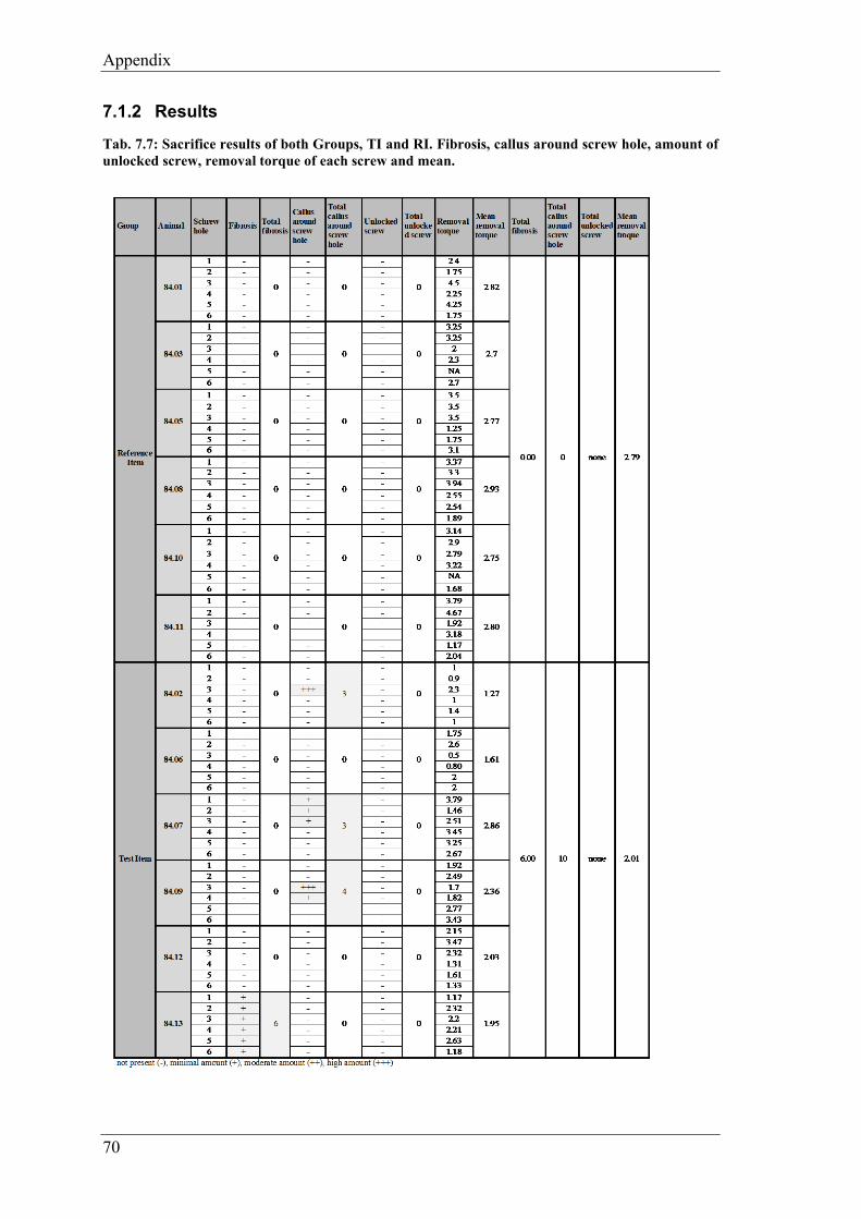
Appendix
70
7.1.2 Results
Tab. 7.7: Sacrifice results of both Groups, TI and RI. Fibrosis, callus around screw hole, amount of unlocked screw, removal torque of each screw and mean.

Appendix
71
Tab. 7.8: Cortical callus formation -in the semiquantitative radiologic evaluation
Tab. 7.9: RUST score -in the semiquantitative radiologic evaluation
Tab. 7.10: Callus area cis-cortex -in the semiquantitative radiologic evaluation
Tab. 7.11: Callus area trans-cortex -in the semiquantitative radiologic evaluation
Tab. 7.12: Callus area cranial cortical gap -in the semiquantitative radiologic evaluation
Tab. 7.13: Callus area caudal cortical gap -in the semiquantitative radiologic evaluation
Tab. 7.14: Callus opacity -in the semiquantitative radiologic evaluation
Tab. 7.15: Bone activation: callus around screw tips -in the semiquantitative radiologic evaluation

Appendix
72
Tab. 7.16: Quantitative radiologic evaluation: Mean callus area [cm2] for every sheep (84.01-84.14) of all three projections over 9 weeks: anteroposterior (0°) and two angled planes: anterolateral (275°) and posterolateral (265°).
Tab. 7.17: Quantitative radiologic evaluation: Mean callus area [cm2] of all three projections over 9 weeks: anteroposterior (0°) and two angled planes: anterolateral (275°) and posterolateral (265°).
Tab. 7.18: Quantitative radiologic evaluation: Mean callus area in ap (anteroposterior, 0°) projection over 9 weeks.
Tab. 7.19: Quantitative radiologic evaluation: Mean callus area in anterolateral (275°) projection over 9 weeks.
Tab. 7.20: Quantitative radiologic evaluation: Mean callus area in posterolateral (265°) projection over 9 weeks.

Appendix
73
Tab. 7.21: Biomechanical results for TI and RI: Peak torque, apparent stiffness, yiel point, energy to failure and rotation to failure.
Tab. 7.22: Histomorphometry of total section including measurement of old bone, new bone and non-bone
Tab. 7.23: Histomorphometry of sectoral section including measurement of callus endosteal, callus at cis cortex and callus at trans cortex.
Tab. 7.24: Fluorescence evaluation inclunding amount measurements of calcein green, xylenol orange and oxytetracycline

Appendix
74
Tab. 7.25: Results of thin section evaluation for screw hole and defect area at cis cortex (light grey labeled animals TI group).
Evaluation: Cis cortexTest item: VFLS Variable Fixation Locking ScrewReference Item: Locking Screw Synthes
84.02 TL
84.06 TL
84.07 TR
84.09 TR
84.12 TR
84.13 TL
84.01 TR
84.03 TR
84.05 TR
84.08 TL
84.10 TL
84.11 TL
1. Inflammation
Polymorphonuclear 0 0 0 0 0 0 0 0 0 0 0 0
Eosinophils 0 0 0 0 0 0 0 0 0 0 0 0
Lymphocytes 0 0 0 1 0 1 0 0 0 0 0 0
Plasma cells 0 0 0 0 0 0 0 0 0 0 0 0
Macrophages 3 3 3 2 2 2 2 1 2 1 2 1
Giant cells 1 2 1 1 1 1 0 0 0 0 0 0
Necrosis/ osteolysis 0 0 0 0 0 0 0 0 0 0 0 0
SUB-TOTAL 4 5 4 4 3 4 2 1 2 1 2 1
SUB-TOTAL (x2) 8 10 8 8 6 8 4 2 4 2 4 2
2. Tissue response
Neovascularisation 2 2 1 1 1 1 0 1 0 0 0 0
Fibrosis 2 2 1 1 1 1 0 1 0 0 0 0
Fatty infi ltrate 1 1 1 0 1 1 0 0 0 0 0 0
F.2 SUB-TOTAL 5 5 3 2 3 3 0 2 0 0 0 0
TOTAL (1.+2.) 13 15 11 10 9 11 4 4 4 2 4 2
GROUP TOTAL
Average (Ø)
Ø TI - Ø RI ¹Traumatic necrosis 0 0 0 0 0 0 0 0 0 0 0 0
Foreign debris (*: metallosis; "granulated, finely stippled material free and cell associated) 3" * 3" 3" * 3" * 3" * 3" * 3* 3* 3* 3* 3* 3*
Osteoclasts 2 2 1 0 1 1 1 1 1 1 1 1
Bone activity S S S S S S F F S S S S
Defect unity (thick section) 4 4 4 4 4 4 4 4 4 4 4 4
Conclusion: Under the conditions of this study, the Test Item was considered to demonstrate the following: minimal or no reaction (0.0 up to 2.9); x slight reaction (3.0 upt to 8.9);__ moderate reaction (9.0 upt to 15.0); severe reaction (>15.1)to the tissue as compared to the Reference Item.
¹ Used to determine irritant ranking shown below as the conclusion. A negative difference is recorded as zero.
Reference Item
Bio
com
patib
ility
69 20
11,50 3,33
8,17
Bone remodeling
additional observations
Animal IDTest item

Appendix
75
Tab. 7.26: Results of thin section evaluation for screw hole and defect area at trans cortex (light grey labeled animals TI group).
Evaluation: Trans cortexTest item: VFLS Variable Fixation Locking ScrewReference Item: Locking Screw Synthes
84.02 TL
84.06 TL
84.07 TR
84.09 TR
84.12 TR
84.13 TL
84.01 TR
84.03 TR
84.05 TR
84.08 TL
84.10 TL
84.11 TL
1. Inflammation
Polymorphonuclear 0 0 0 0 0 0 0 0 0 0 0 0Eosinophils 0 0 0 0 0 0 0 0 0 0 0 0Lymphocytes 0 0 0 0 0 0 0 0 0 0 0 0Plasma cells 0 0 0 0 0 0 0 0 0 0 0 0Macrophages 1 2 1 2 2 2 2 0 0 0 0 0Giant cells 0 2 0 1 0 1 1 0 0 0 0 0Necrosis/ osteolysis 0 0 0 0 0 0 0 0 0 0 0 0SUB-TOTAL 1 4 1 3 2 3 3 0 0 0 0 0SUB-TOTAL (x2) 2 8 2 6 4 6 6 0 0 0 0 02. Tissue responseNeovascularisation 1 1 0 1 1 1 1 0 0 0 0 0Fibrosis 1 1 0 1 1 1 1 0 0 0 0 0Fatty infi ltrate 0 0 0 0 0 0 0 0 0 0 0 0F.2 SUB-TOTAL 2 2 0 2 2 2 2 0 0 0 0 0TOTAL (1.+2.) 4 10 2 8 6 8 8 0 0 0 0 0GROUP TOTALAverage (Ø)Ø TI - Ø RI ¹Traumatic necrosis 0 0 0 0 0 0 0 0 0 0 0 0
Foreign debris (*: metallosis; "granulated, finely stippled material free and cell associated)
3" 3" 3" 3" 3" 3" 3* 0 0 3* 3* 0
Osteoclasts 1 2 1 2 1 1 1 1 1 1 1 1
Bone activity F S S S S S F S S F S S
Defect unity (thick section) 4 1 4 3 4 4 4 0 4 3 4 4
Conclusion: Under the conditions of this study, the Test Item was considered to demonstrate the following: x minimal or no reaction (0.0 up to 2.9); slight reaction (3.0 upt to 8.9); moderate reaction (9.0 upt to 15.0); severe reaction (>15.1)to the tissue as compared to the Reference Item.
¹ Used to determine irritant ranking shown below as the conclusion. A negative difference is recorded as zero.
Bio
com
patib
ility
38 86,33 4,33
2,00
Bone remodelling
additional observations
Animal IDTest item Reference Item

Appendix
76
Tab. 7.27: Lymph nodes score results of structure changes, nonlocal cells, presence foreign material, amount of extracellular foreign material and amount of cells with intracellular foreign material.

Appendix
77
7.2 Figures
7.2.1 Material and Methods
Fig. 7.1: Surgical procedure step by step. Detailed explanation for 1) till 12) see chapter 3.4.1 surgical procedure.

Appendix
78
Fig. 7.2: Surgery Protocol page 1: For screw 1-6 the screw order, screw length and comments have been noted.
Fig. 7.3: Surgery Protocol page 2: Detailed check-list for the surgery procedure.

Appendix
79
Fig. 7.4: Sacrifice procedure from the beginning (slaughtering by Paul) till histology preparation
Fig. 7.5: Sacrifice protocol for each screw: Control of locking state, micromotion, removal torque, callus/ ossification around the implants, sleeve absence and fibrosis around screw hole. Including empty space for comments and notes.

Appendix
80
Fig. 7.6: Radiographs in three projections, week 9. On the left: animal 84.01 (RI, right tibia) and on the right: animal 84.09 (TI, right tibia).
Fig. 7.7: Quantitative radiologic evaluation of the callus area (green line) measured with Osirix.
Fig. 7.8: Biomechanical testing at ETH: Preparation of the tibia (Picture left), potted distal part of the tibia (picture middle), set up (picture right).

Appendix
81
7.2.2 Results
Fig. 7.9: Sacrifice pictures of a right sheep tibia (TI, animals 84.09)
Fig. 7.10: Sacrifice pictures of a left sheep tibia (TI, animal 84.13)

Appendix
82
Fig. 7.11: Sacrifice pictures of a right sheep tibia (RI, animal 84.05)
Fig. 7.12: Microradiographs of all animals
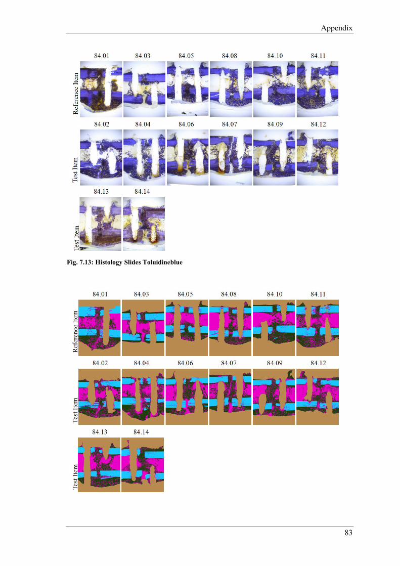
Appendix
83
Fig. 7.13: Histology Slides Toluidineblue

Appendix
84
Fig. 7.14: Histomorphometry total section analysis
Fig. 7.15: Histomorphometry sectoral analysis
Fig. 7.16: Fluroescence overlay (calcein green, xylenol orange, oxytertracycline)

Appendix
85
Fig. 7.17: Histomorphometry calcein green
Fig. 7.18: Histomorphometry xylenol orange
Fig. 7.19: Histomorphometry oxytetracycline

Appendix
86
Fig. 7.20: Animal 84.02 TI, cis cortex (C) with area of resorbed sleeve, overview picture, toluidine blue staining, 45x magnification: screw hole (S) visible with fibrous tissue (F) next to newly formed bone (marked in grey), in the fibrous tissue area macrophages with residuals of sleeve material as well as giant cells detected.
Fig. 7.21: Animal 84.10 RI, cis cortex (C) with screw hole, overview picture, toluidine blue staining 45x magnification: screw hole clearly visible (S), newly formed bone (marked in grey) no fibrosis.
Fig. 7.22: Animal 84.02 TI, cis cortex with area of resorbed sleeve, toluidine blue staining, 100x magnification: Screw hole (S) with fibrous tissue (F), residuals of sleeve material (finely stippled) free and cell associated in macrophages (area marked in grey), newly formed bone with thick osteoid seam (N) and active osteoblasts next to the fibrous tissue.
Fig. 7.23: Animal 84.02 TI, cis cortex with area of resorbed sleeve, toluidine blue staining, 200x magnification: Screw hole (S) visible with fibrous tissue (F), residuals of sleeve material (finely stippled) free (orange arrow) and cell associated in macrophages (black arrows).
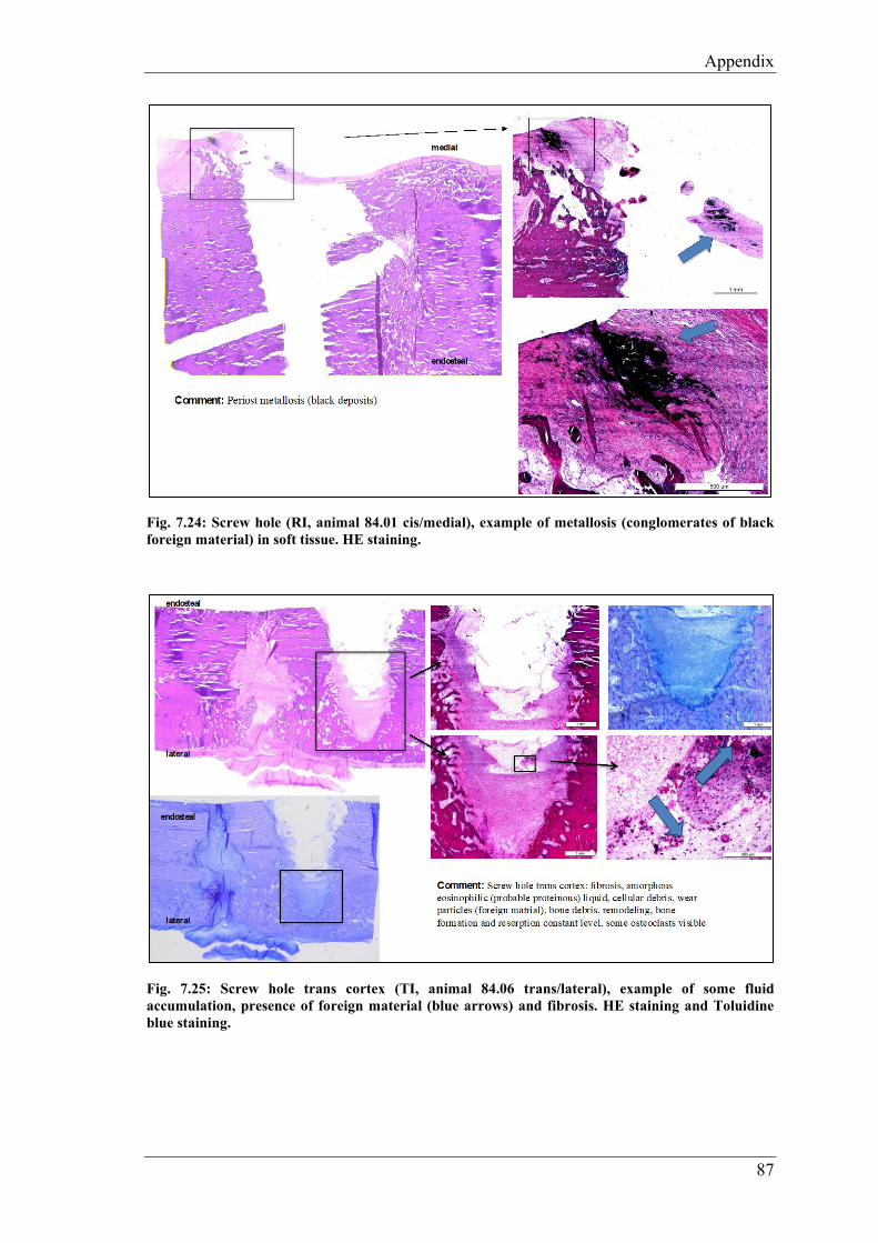
Appendix
87
Fig. 7.24: Screw hole (RI, animal 84.01 cis/medial), example of metallosis (conglomerates of black foreign material) in soft tissue. HE staining.
Fig. 7.25: Screw hole trans cortex (TI, animal 84.06 trans/lateral), example of some fluid accumulation, presence of foreign material (blue arrows) and fibrosis. HE staining and Toluidine blue staining.

Appendix
88
Fig. 7.26: Screw hole (TI, animal 84.07 cis/medial), example of fatty infiltrate from the bone marrow. HE staining
Fig. 7.27: Inguinal right lymph node, animal 84.02, TI group. Visible foamy (epitheloid-like) macrophage aggregates with brownish-beige containing small particles (1-3µm) foreign residuals (blue arrow), which does not polarize, groups located mostly along the lymp vessels within the cortex.


Danksagung
Danksagung
Mein grösster Dank geht an Frau Prof. Dr. med. vet. Brigitte von Rechenberg. Für die
Möglichkeit eine Dissertation bei der MSRU schreiben zu dürfen und für die
Unterstützung, wie für die spannenden und lehrreichen Diskussionsrunden danke ich
ganz besonders.
Herr Prof. Dr. Stephen Ferguson danke ich für die Übernahme des Korreferats.
Ein grosses Dankeschön geht an PhD Dr. med. vet. Karina Klein. Sie hat mich immer
sehr gut unterstützt und mir bei der ganzen Studie und beim Anfertigen der Dissertation
geholfen. Sie war immer mit einem Lächeln anzutreffen und mit ihr hat die Arbeit sehr
viel mehr Freude gemacht.
Meinem Projekt Partner PhD Dr. med. vet. Stefano Brianza bedanke ich mich herzlich
für seine geniale Idee und für die tolle Zusammenarbeit.
Dr. med. Michael Plecko bedanke ich mich, dass er den weiten Weg von Graz nach
Zürich auf sich genommen hat, um zu operieren. Mit seiner präzisen Chirurgie und mit
seinem enormen Wissen hat er uns sehr bereichert. Er war immer sehr zuvorkommend
und hat mit seiner positiven Art und Weise für ein gutes Arbeitsklima gesorgt.
Prof. Dr. med. vet. Mark Flückiger danke ich für die Mithilfe beim Auswerten der
Radiologiebilder.
Bei all meinen Doktorandengspändlis bedanke ich mich ganz fest für die tolle Zeit, die
wir im und auch außerhalb des Büros zusammen verbringen durften: Raphael Arz,
Konrad Finck, Anna Geks, Vanessa Graf, Isabel Heckel, Martina Heygen, Anna
Kaczmarek, Claudia Michaelis, David Michalik, Alina Renner, Katharina Siwy,
Alina Steigerwald und Christina Wiezorek.
Ohne unsere Anästhesistin wären unsere Operationen gar nicht möglich gewesen.
Deshalb geht ein grosses Dankeschön an Dr. med. vet. Dagmar Verdino, die immer
mit Kaffee am frühen Morgen für gute Laune sorgte.


Danksagung
Dr. med. vet. Myrna Gunning war fast immer an meiner Seite beim Casten und
Röntgen. Ebenso danke ich ihr auch für die sprachliche Unterstützung bei dieser Arbeit.
Rosita Walther danke ich für den immerwährend guten Überblick beim Sacrifice und
auch für die Hilfe beim Bearbeiten der Histologieproben.
Ich danke Aymone Lenisa für die Unterstützung im Labor und für die sorgfältige
Arbeit.
Dr. med. vet. Aga Agnieszka Karol danke ich für die spannenden Auswertungen der
Dünnschnitte und Lymphknoten.
Bei Silvana Ressegatti, Käthi Kämpf und der Familie Knüsel bedanke ich mich für
die Pflege und die gute Fürsorge der Schafe.
Meinen Eltern und meinen Freunden danke ich für die mentale Unterstützung.


Curriculum Vitae
Curriculum Vitae
Vorname Name Katrin Planzer
Geburtsdatum 10.09.1991
Geburtsort Altdorf UR
Nationalität Schweizerin
Heimatort Bürglen UR
8/1998 – 7/2004 Primarschule, Ettiswil LU, Schweiz
8/2004 - 6/2010 Kantonsschule Willisau LU, Schweiz
Juni 2010 Matura, Kantonsschule KSW, Willisau, Schweiz
9/2010 – 8/2011 Biologiestudium, Universität Zürich, Schweiz
9/2011 – 12/2016 Bachelor- und Masterstudium Veterinärmedizin, Universität
Zürich, Schweiz
Januar 2017 Abschlussprüfung vet. med.
Universität Zürich, Schweiz
6/2017 – 9/2018 Anfertigung der Dissertation
unter Leitung von Prof. Dr. med. vet. Brigitte von
Rechenberg
am Institut für Molekulare Mechanismen bei Krankheiten
der Vetsuisse-Fakultät Universität Zürich
Direktor Prof. Dr. med. vet. et phil. II Michael Hottiger
1/2019 - dato Internship, Bessy’s Kleintierklinik, Regensdorf, Schweiz