Embed Size (px)
Citation preview
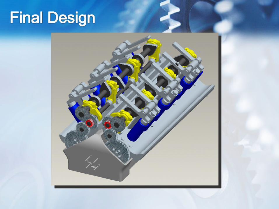
Variable Geometry Camshaft
Scott LakeMatt PhillipsZachary LightnerRyan KowalewskiMatt Griffey
Sponsor:Gary Griffiths

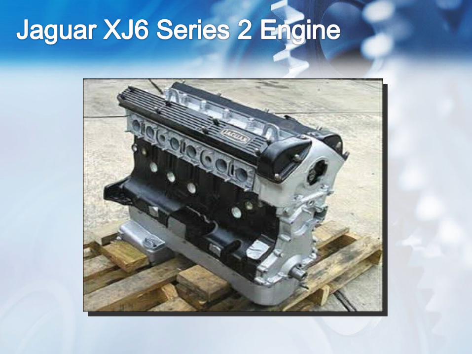
• Background of Invention• Jaguar XJ6 Series 2 Engine• CAD Model Development• Dynamic Analysis
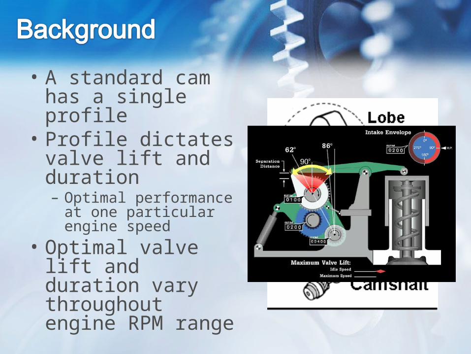
• A standard cam has a single profile
• Profile dictates valve lift and duration– Optimal performance at
one particular engine speed
• Optimal valve lift and duration vary throughout engine RPM range
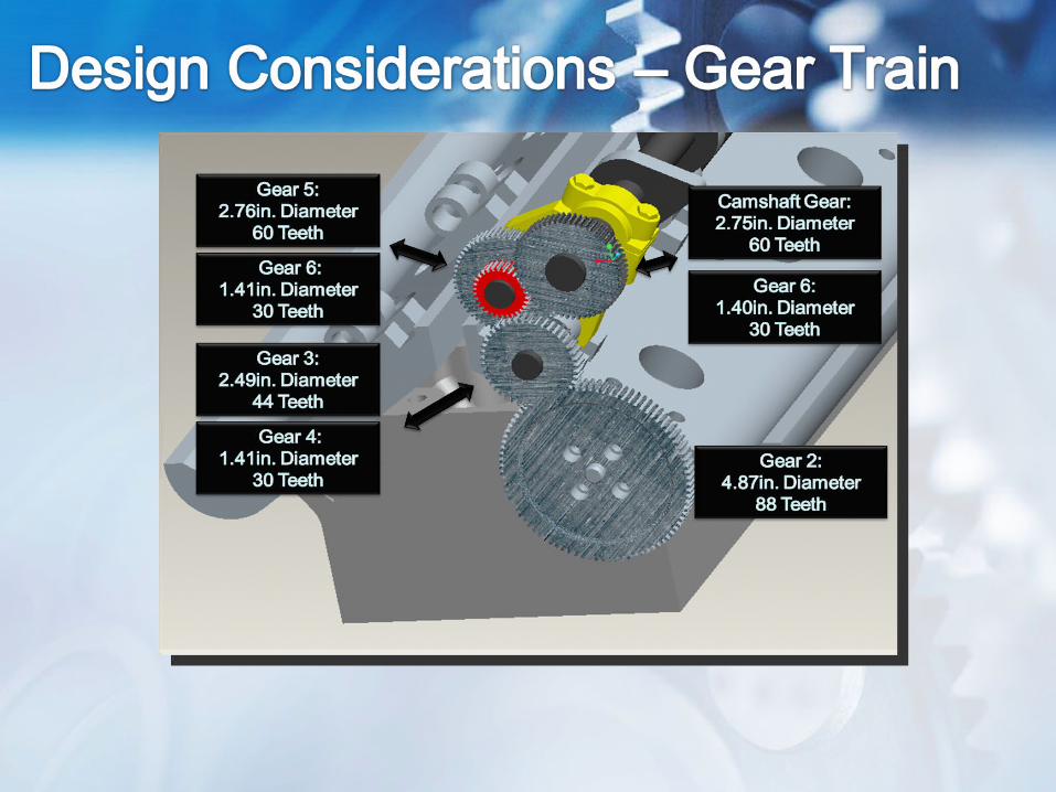
• Increased volumetric efficiency• 4:1 Gear ratio mechanism for transferring
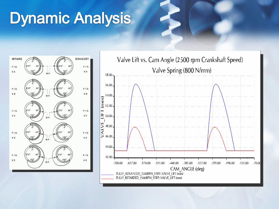
torque from the input gear to the camshaft• 180° of crankshaft rotation resulting in 90° of
valve duration• 240° of crankshaft rotation resulting in 120° of
valve duration• Fulcrum Rotation of no more than 24°• Translational movement of rocker tower
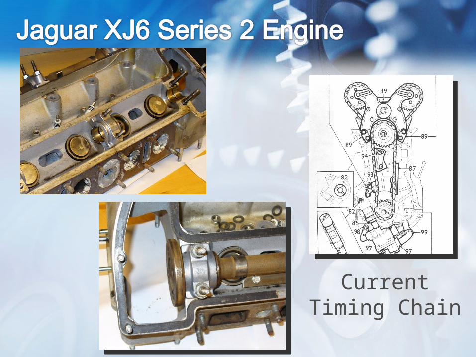
Current Timing Chain
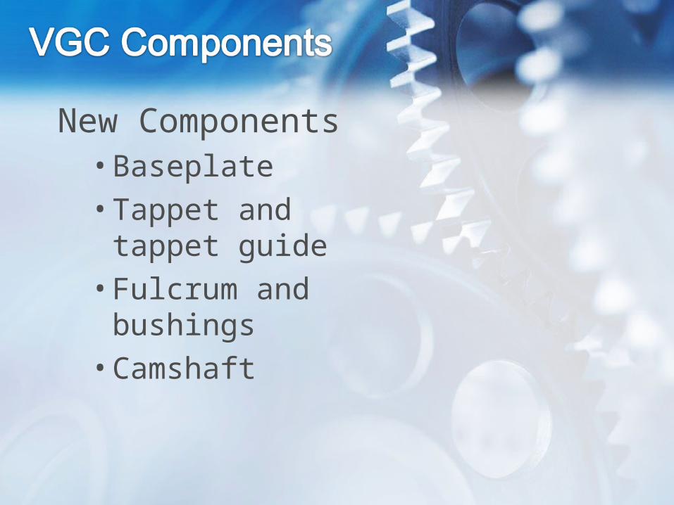
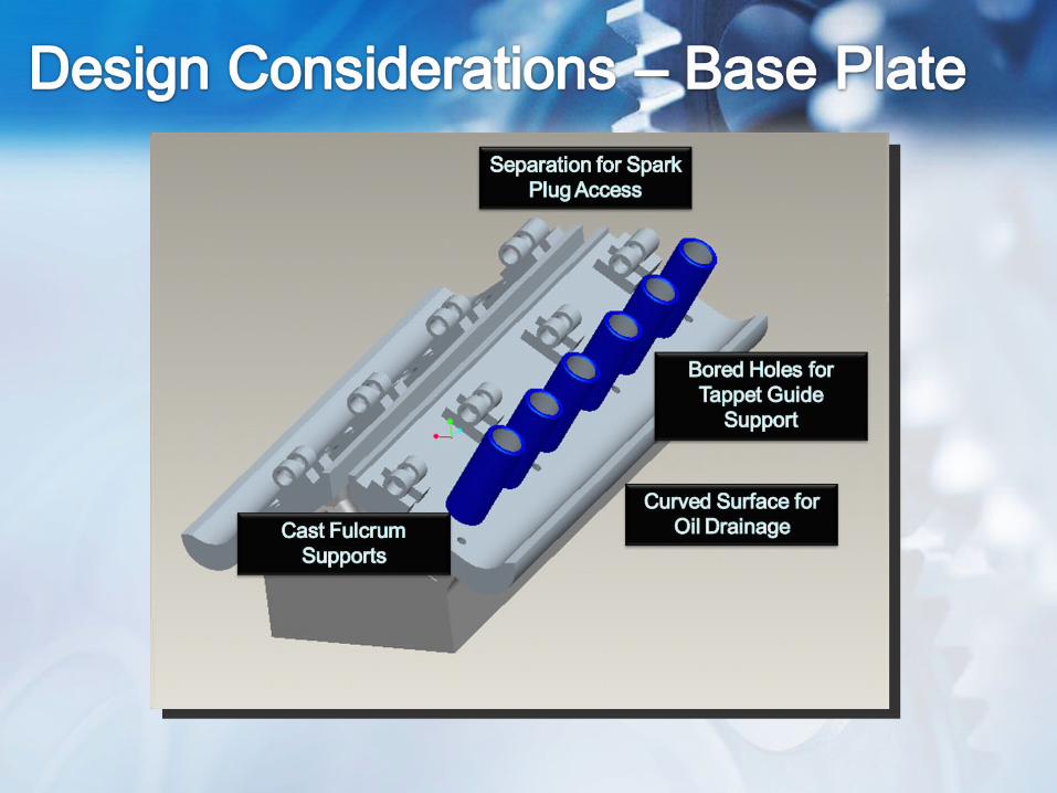
New Components• Baseplate
• Tappet and tappet guide
• Fulcrum and bushings
• Camshaft
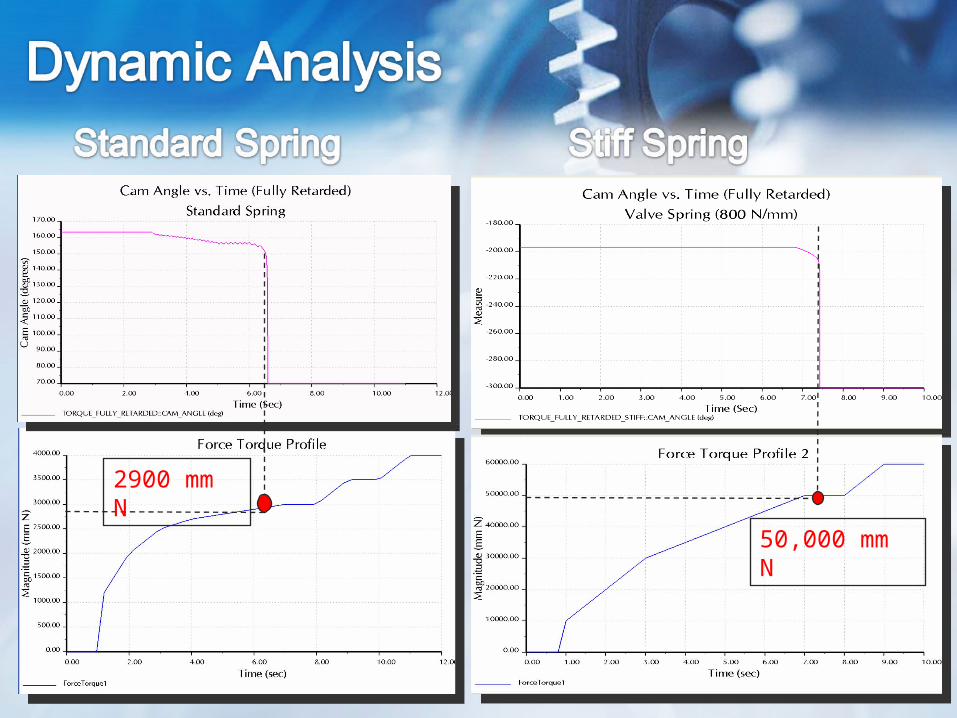
2900 mm N
50,000 mm N
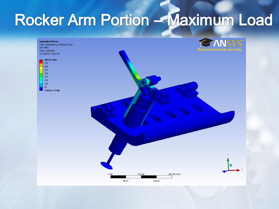
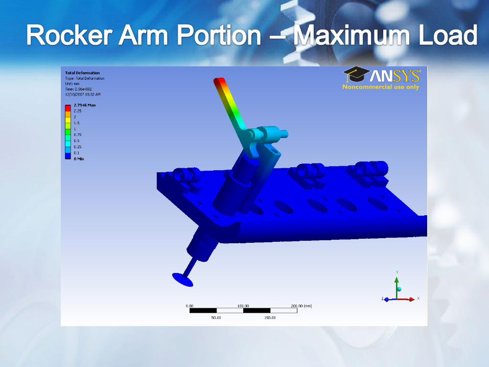
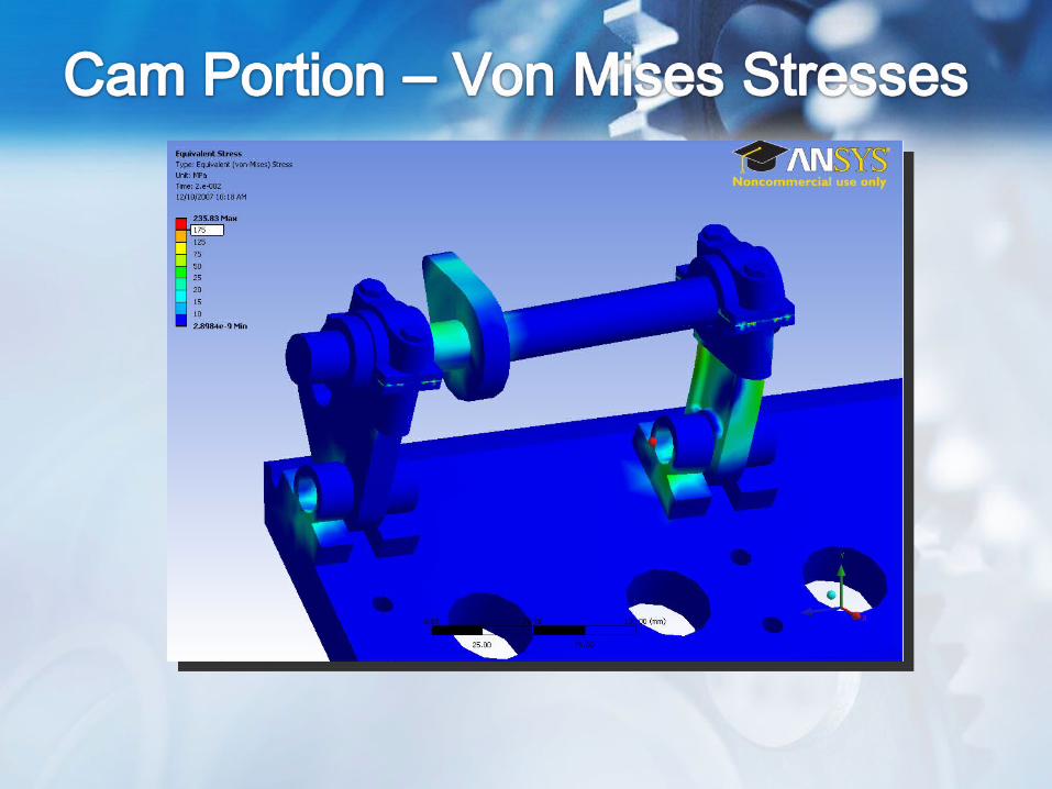
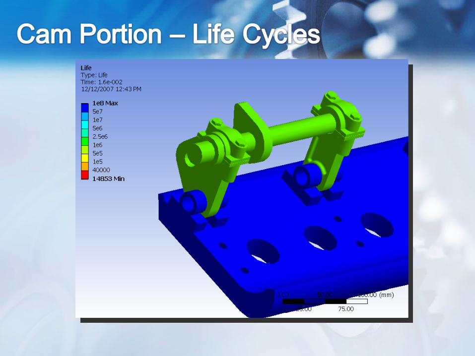
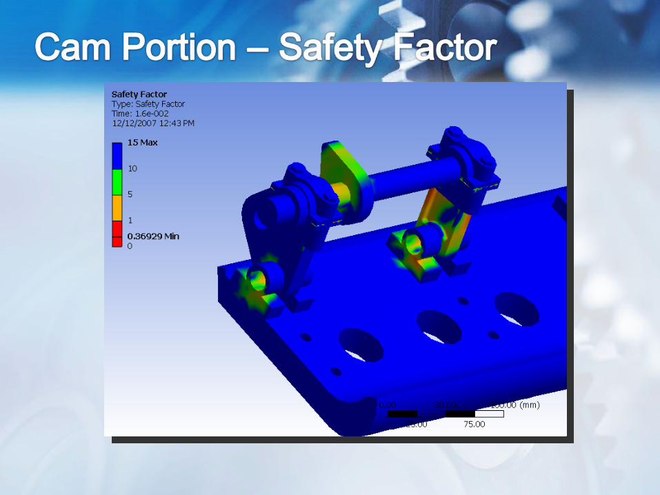
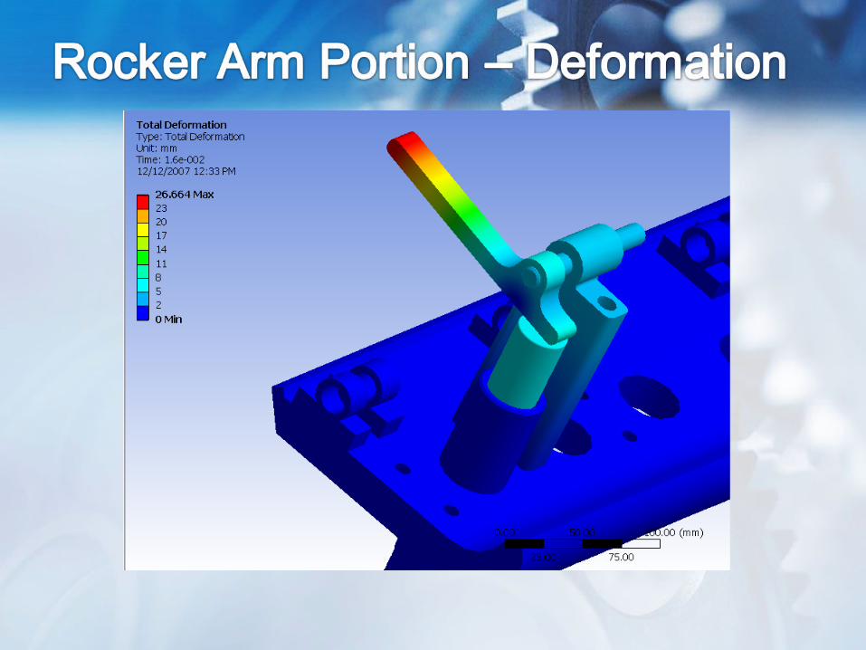
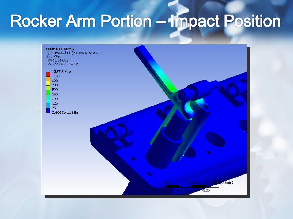
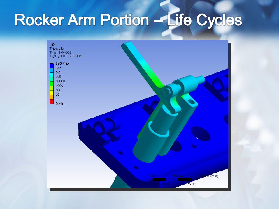
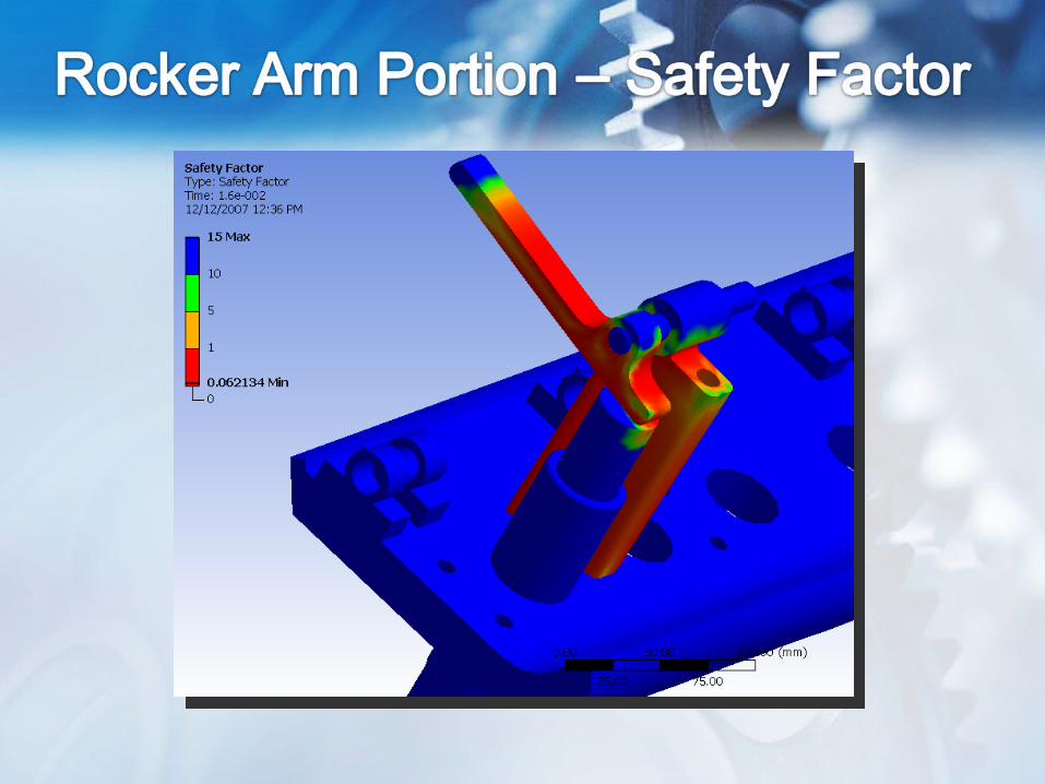
• Divide model into two portions at cam – rocker arm interface
• Observe deformation and Von Mises stresses at two distinct times:– Impact position (Cam initially makes contact
with rocker arm)– Maximum Load position (Maximum normal
force between cam and rocker arm)
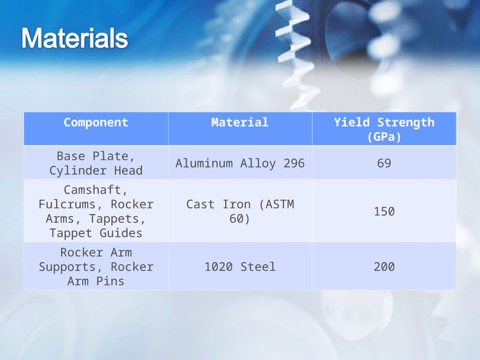
Component Material Yield Strength (GPa)
Base Plate, Cylinder Head
Aluminum Alloy 296 69
Camshaft, Fulcrums, Rocker Arms, Tappets,
Tappet GuidesCast Iron (ASTM 60) 150
Rocker Arm Supports, Rocker Arm Pins
1020 Steel 200
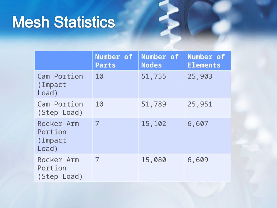
Number of Parts
Number of Nodes
Number of Elements
Cam Portion (Impact Load)
10 51,755 25,903
Cam Portion (Step Load)
10 51,789 25,951
Rocker Arm Portion (Impact Load)
7 15,102 6,607
Rocker Arm Portion (Step Load)
7 15,080 6,609
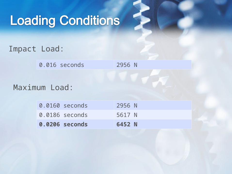
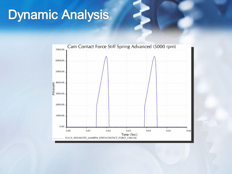
0.016 seconds 2956 N
Impact Load:
Maximum Load:
0.0160 seconds 2956 N
0.0186 seconds 5617 N
0.0206 seconds 6452 N
• Redesign of VGC system to be located outboard of tappet guide assembly
• Reduce generated forces by reducing separation distance, cam inertia
• Explore alternate 4:1 gear ratio designs• Component Refinement – Redesign of
high-stress components


APPENDIX
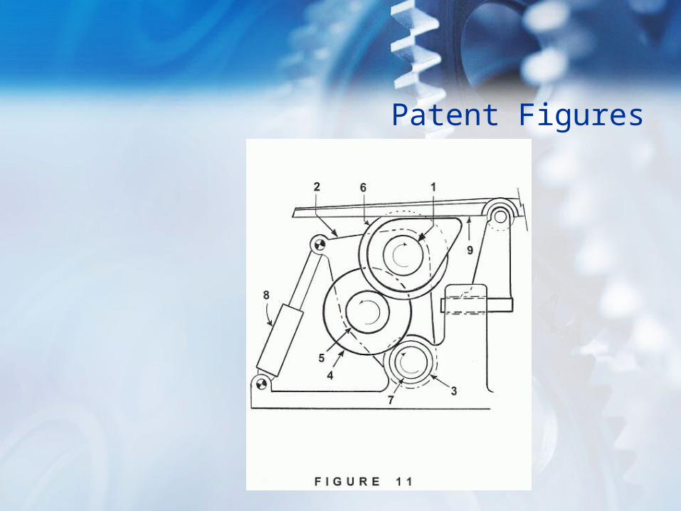
Patent Figures
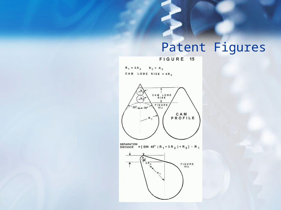
Patent Figures
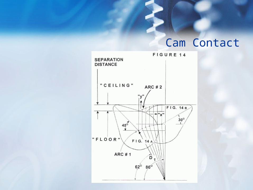
Cam Contact
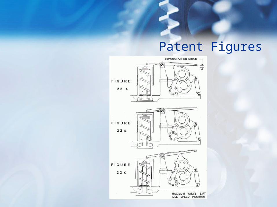
Patent Figures
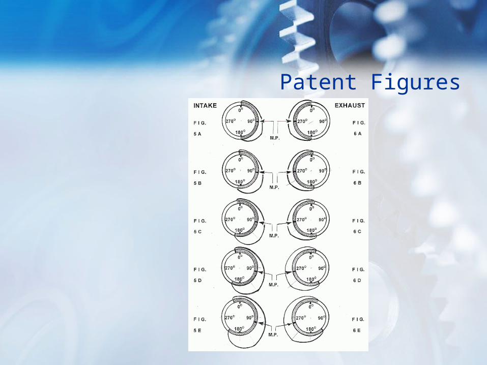
Patent Figures