Embed Size (px)
DESCRIPTION
In this study, a novel variable impedance control for a lower-limb rehabilitation robotic system using voltage control strategy is presented. The majority of existing control approaches are based on control torque strategy, which require the knowledge of robot dynamics as well as dynamic of patients. This requires the controller to overcome complex problems such as uncertainties and nonlinearities involved in the dynamic of the system, robot and patients. On the other hand, how impedance parameters must be selected is a serious question in control system design for rehabilitation robots. To resolve these problems this paper, presents a variable impedance control based on the voltage control strategy. In contrast to the usual current-based (torque mode) the use of motor dynamics lees to a computationally faster and more realistic voltage-base controller. The most important advantage of the proposed control strategy is that the nonlinear dynamic of rehabilitation robot is handled as an e
Citation preview
International Journal of Robotics, Vol. 4, No. 3, (2015) A. Khoshdel et al., 46-54
*. Corresponding address: Ferdowsi University of Mashhad, Mashhad, Iran,
Tel.: +98 2184063288; fax: +982188674748., E-mail address: [email protected].
46
Variable Impedance Control for Rehabilitation
Robot using Interval Type-2 Fuzzy Logic
V. Khoshdela, A. Akbarzadeh a, * and H. Moeenfard a a Center of Excellence on Soft Computing and Intelligent Information Processing, Mechanical Engineering Department, Ferdowsi University of
Mashhad, Iran
A R T I C L E I N F O A B S T R A C T
Article history:
Received: June 18, 2015. Received in revised form:
October 17, 2015.
Accepted: October 26, 2015.
In this study, a novel variable impedance control for a lower-limb rehabilitation
robotic system using voltage control strategy is presented. The majority of existing
control approaches are based on control torque strategy, which require the knowledge
of robot dynamics as well as dynamic of patients. This requires the controller to
overcome complex problems such as uncertainties and nonlinearities involved in the
dynamic of the system, robot and patients. On the other hand, how impedance
parameters must be selected is a serious question in control system design for
rehabilitation robots. To resolve these problems this paper, presents a variable
impedance control based on the voltage control strategy. In contrast to the usual
current-based (torque mode) the use of motor dynamics lees to a computationally
faster and more realistic voltage-base controller. The most important advantage of the
proposed control strategy is that the nonlinear dynamic of rehabilitation robot is
handled as an external load, hence the control law is free from robot dynamic and the
impedance controller is computationally simpler, faster and more robust with
negligible tracking error. Moreover, variable impedance parameters based on Interval
Type-2 Fuzzy Logic (IT2Fl) is proposed to evaluate impedance parameters. The
proposed control is verified by a stability analysis. To illustrate the effectiveness of
the control approach, a 1-DOF lower-limb rehabilitation robot is designed. Voltage-
based impedance control are simulated through a therapeutic exercise consist of
Isometric and Isotonic exercises. Simulation results show that the proposed voltage-
based variable impedance control is superior to voltage-based impedance control in
therapeutic exercises.
Keywords:
Impedance control
Rehabilitation robot
Interval type-2 fuzzy logic
Voltage-Based control
1. Introduction
Nowadays, neurological impairments such as Stroke
and Cerebral Palsy are the most common forms of
disability in adults and children, respectively. People
with neurological impairment often have compromised
volitional control of their arm and legs limiting their
ability to undertake activities of daily living such as
walking. The core mechanisms of rehabilitation
interventions to promote lower limb function involve
intensive practice of functional tasks, which drives
neural plasticity to improve motor skills. However
International Journal of Robotics, Vol. 4, No. 3, (2015) A. Khoshdel et al., 46-54
47
weakness of the lower limb makes it difficult for the
neurologically impaired to practice at the necessary
intensity. One-way of providing the required support
for the neurologically impaired is to utilize
rehabilitation robotic technology to enable practice of
useful lower limb movements. The rehabilitation
robotics enable the control of the spatial and temporal
characteristics of movements [1].
Control is great challenge in rehabilitation robot
because the robot is interacting with patients and
always a lot of uncertainty is been in this field.
Widespread research activities have been performed to
control system design of rehabilitation robot in recent
years. To perform therapeutic exercises, various control
methods such as position control, force control, hybrid
position-force control and impedance control have been
applied for the rehabilitation robots. Hybrid control and
impedance control are two commonly used control
methods. The hybrid control was successfully
implemented on the LOKOMAT robotic system [2-4].
Compared with other control methods, the impedance
control is more effective and flexible to apply a wide
range of rehabilitation exercises in the presence of
uncertainties [5]. The therapeutic robots such as MIT-
MANUS employ impedance control for passive and
resistive exercises [6]. An impedance control law is a
desired dynamics, which a rehabilitation robot should
show in contact with human to perform a commanded
therapeutic exercise. Because of applying impedance
control, the robotic system will interact with the
environment such a mass-spring-damper system in
response to the applied force from the environment.
In rehabilitation robot and other case that the
environment’s dynamics changing in during task
execution has been observed that impedance control
with fixed impedance parameters is not effective [7].
Moreover, how impedance parameters must be selected
is great question in control system design for
rehabilitation robots. Parameters of impedance control
are often tuned empirically and intuitively; hence, the
system designers have to adjust them according to
individuals. Due to this issue, users sometimes have to
adapt themselves to the controlled machine when the
tuning condition given by the designer is not adequate
for the user [8].
To resolve these problems variable impedance has
been proposed which impedance parameters adapted
according to various characteristics in real time.
Impedance parameters have been regulated by some
different ways such as varying impedance parameters
with fuzzy logic systems [9] adaptive strategies [10]
and switching mechanisms [11]. Selsuk et al. proposed
impedance control, which gain of mechanical
impedance was modified by a fuzzy logic PID
controller [12].
G. Xu et al have used fuzzy and fuzzy neural
network impedance controller to regulate impedance
parameters،. In this studies control method needs to
impaired limb parameters for regulate impedance
parameters [13, 14]. Also G. Xu et al presented
adaptive hierarchical control for upper limb
rehabilitation which combines the high-level
progressive resistive supervisory controller with a low-
level adaptive resistive force triggered controller [15].
Y. Choi et al have proposed a novel robotic adaptive
and automatic presentation of tasks. In this study, the
high-level adaptive task scheduler regulated task and
difficulty of exercise according to physiotherapist, prior
practice database and task bank. Then function task
model generated desired trajectory for admittance
controller [16].
Impedance control is basically defined as a torque
control scheme. In the other words, the joint torques of
robot are commended to implement impedance control.
For this purpose, the controller should overcome
complex problems such as uncertainty and nonlinearity
involved in the dynamics of the robotic system. Also in
torque control scheme, control system design depends
on dynamics of patient's limb. Dynamics of patient's
limb is nonlinear, unknown and Varies with time.
Furthermore, majority of the proposed control
approaches have ignored the dynamics of actuators,
which are important in motion control and generally
this proposed control approaches need to use estimator
to estimate patient’s limb parameters [15, 16]. In the
torque based control approaches, it is assumed that the
actuators can provide the commanded torques for the
robot joints. However, this assumption may not be
satisfied perfectly due to some practical problems such
as the actuator dynamics, actuator saturation and
sensing limitations.
In order to overcome nonlinearity of the robotic
system and considering the actuators and moreover to
create a robot with the ability to adapt to the patient's
status in real-time, this paper presents a novel adaptive
impedance control for a rehabilitation robot, which can
be less dependent on the model of robot dynamics. The
impedance parameters are regulated in real-time by
IT2FLS according to position error, velocity error and
error of force. The proposed control is developed based
on the voltage control strategy [17] that differs from the
commonly used strategy called, torque control strategy.
Compared with a torque control scheme, it is simpler,
less computational and more efficient.
The remaining of this paper is organized as follows:
Section 2 formulates the dynamics of the rehabilitation
robot. Section 3 develops Interval Type-2 Fuzzy Logic
Systems. In section 4, we presented the impedance
control to perform recommended exercises by a
physiotherapist specializing in knee therapies. Section 5
presents stability analysis and evaluates the control
International Journal of Robotics, Vol. 4, No. 3, (2015) A. Khoshdel et al., 46-54
48
performance. Section 6 illustrates the simulation
results. Finally, Section 7 concludes the paper.
2. System Dynamics
In general, an electrically driven rehabilitation robot consists of 𝑛 links interconnected at 𝑛 joints into an open kinematic chain. Each link is driven by a permanent magnet dc motor through the gears. We assume that both the links and the couplings between the electric motors and links are perfectly rigid. The dynamic model [9] can thus be described by 𝑛 generalized coordinates representing the degrees-of-freedoms of the 𝑛 joints as
(1) 𝑫𝒓(𝒒)�̈� + 𝑪𝒓(𝒒, �̇�)�̇� + 𝒈𝒓(𝒒) + 𝝉𝒆 = 𝝉𝒓
where 𝒒 ∈ 𝑹𝒏 is the vector of joint positions, 𝑫𝒓(𝒒) ∈𝑹𝒏 is the matrix of manipulator inertia, 𝑪𝒓(𝒒, �̇�)�̇� ∈ 𝑹𝒏 is the vector of centrifugal and Coriolis torques, 𝒈𝒓(𝒒) ∈𝑹𝒏 is the vector of gravitational torques, 𝝉𝒆 ∈ 𝑹𝒏 is the vector of load torque, and 𝝉𝒓 ∈ 𝑹𝒏 is the torque vector of robot. Note that vectors and matrices are bold for clarity.
The load torque is actually provided by the human lower limb located on the robot express as
(2) 𝑫𝒆(𝒒)�̈� + 𝑪𝒆(𝒒, �̇�)�̇� + 𝒈𝒆(𝒒) + 𝝉𝒉 = 𝝉𝒆
where associated with human body, 𝑫𝒆(𝒒) ∈ 𝑹𝒏 is
the inertia matrix, 𝑪𝒆(𝒒, �̇�)�̇� ∈ 𝑹𝒏 is the vector of centrifugal and Coriolis torques, 𝒈𝒆(𝒒) ∈ 𝑹𝒏 is the vector of gravitational torques, 𝝉𝒉 ∈ 𝑹𝒏 is the vector of generated torque by human. Note that vectors and matrices are bold for clarity.
The mechanical section of the rehabilitation robot is obtained by substituting (2) into (1) to obtain
(3) 𝑫(𝒒)�̈� + 𝑪(𝒒, �̇�)�̇� + 𝒈(𝒒) + 𝝉𝒉 = 𝝉𝒓
where
𝑫(𝒒) = 𝑫𝒓(𝒒) + 𝑫𝒆(𝒒) 𝑪(𝒒) = 𝑪𝒓(𝒒, �̇�) + 𝑪𝒆(𝒒, �̇�)
𝒈(𝒒) = 𝒈𝒓(𝒒) + 𝒈𝒆(𝒒)
(4)
(5)
(6)
The electric motors provide the joint torques of the robot as follows
𝑱𝒎𝒓−𝟏�̈� + 𝑩𝒎𝒓−𝟏�̇� + 𝒓𝝉𝒓 = 𝝉𝒎 (7) where 𝝉𝒎 ∈ 𝑹𝒏 is the torque vector of motors, 𝑱𝒎,
𝑩𝒎 and 𝒓 are the 𝒏 × 𝒏 diagonal matrices for motor coefficients namely the inertia, damping, and reduction gear, respectively. Vectors of the joint velocities �̇� and the motor velocities �̇�𝒎 ∈ 𝑹𝒏 are related through the gears to yield
�̇� = 𝒓�̇�𝒎 (8) In order to obtain the motor voltages as the inputs of
system, we consider the electrical equation of geared permanent magnet dc motors in the matrix form,
𝑹𝑰𝒂 + 𝑳�̇�𝒂 + 𝑲�̇� + 𝝋 = 𝑽 (9)
where 𝑲 = 𝑲𝒃𝒓−𝟏, 𝑽 ∈ 𝑹𝒏 is the vector of motor voltages, 𝐈𝐚 ∈ 𝑹𝒏 is the vector of motor currents, and 𝛗 ∈ 𝑹𝒏 is the vector of external disturbances. 𝑹, 𝑳 and 𝑲𝒃 represent the 𝑛 × 𝑛 diagonal matrices for the coefficients of armature resistance, inductance, and back-emf constant, respectively.
The motor torque vector τm as the input for dynamic equation (14) is produced by the motor current vector,
𝛕𝐦 = 𝑲𝒎𝑰𝒂 (10) where 𝐾𝑚 is a diagonal matrix of the torque
constants. The state-space model of the electrically driven robot manipulator is introduced by the use of equations (1)-(10) as
�̇� = 𝒇(𝒛) + 𝒃𝑾 + 𝒃𝝋 (11)
where 𝐖 = [𝝉𝒉
𝑽] is considered as the inputs, 𝒛 =
[𝒒 �̇� 𝑰𝒂]𝑻 is the state vector, 𝒃 and 𝒇(𝒛) are of the form
𝒇(𝒛)
= [
𝒛𝟐
𝑨(−(𝑩𝒎𝒓−𝟏 + 𝒓𝑪(𝒛𝟏, 𝒛𝟐))𝒛𝟐 − 𝒓𝒈(𝒛𝟏) + 𝑲𝒎𝒛𝟑)
−𝑳−𝟏(𝑲𝒃𝒓−𝟏𝒛𝟐 + 𝑹𝒛𝟑)]
where
𝑨 = (𝑱𝒎𝒓−𝟏 + 𝒓𝑫(𝒛𝟏))−𝟏
(12)
𝒃
= [
𝟎 𝟎
(𝑱𝒎𝒓−𝟏 + 𝒓𝑫(𝒛𝟏))−𝟏
𝒓𝑱𝒆𝑻(𝒛𝟏) 𝟎
𝟎 𝑳−𝟏
]
𝒓
The state-space equation (11) shows a highly coupled nonlinear large multivariable system. Complexity of the model has been a serious challenge in the literature of robot modelling and control.
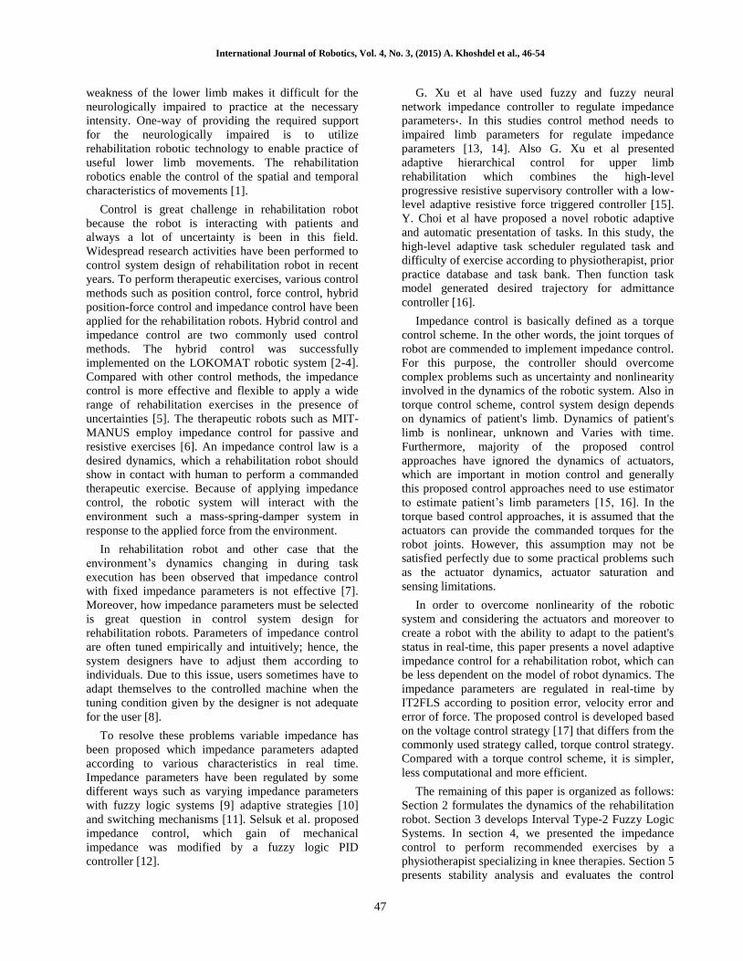
Fig. 1. A schematic of rehabilitation robot
It can be obtained by using (9) and (12) that
(13) 𝑹𝑰𝒂 + 𝑳�̇�𝒂 + 𝑲�̇� = 𝑽
3. Interval Type-2 Fuzzy Logic Systems
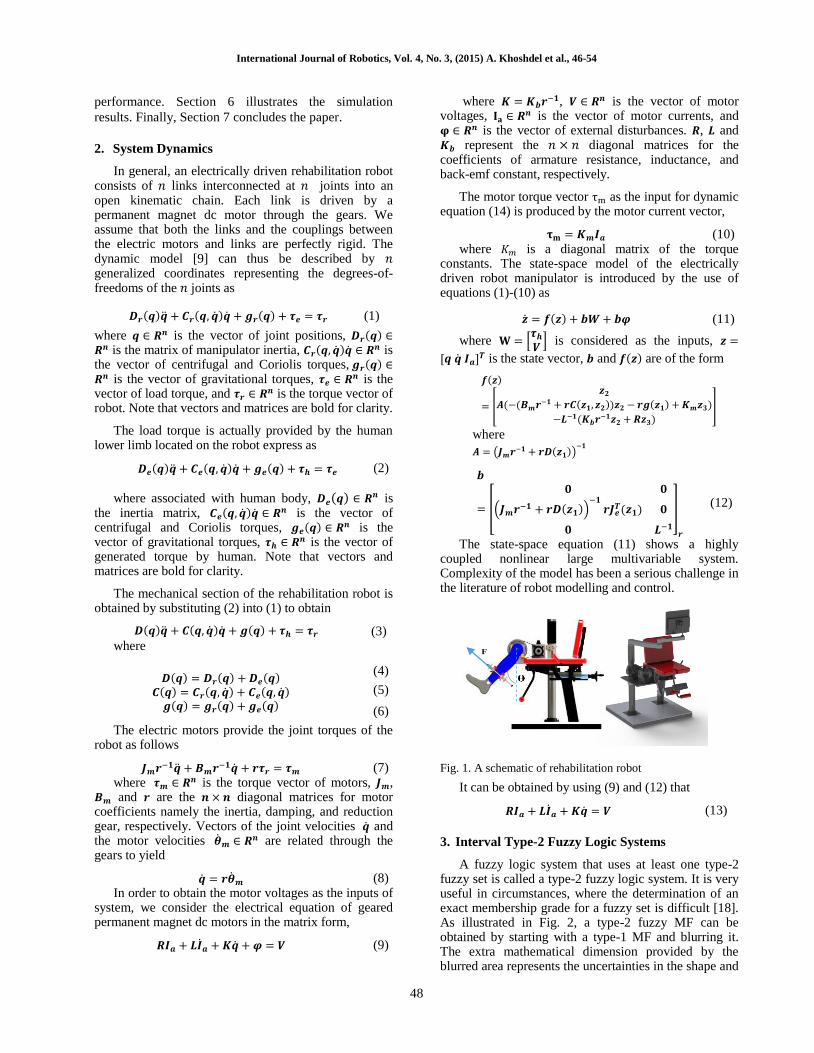
A fuzzy logic system that uses at least one type-2 fuzzy set is called a type-2 fuzzy logic system. It is very useful in circumstances, where the determination of an exact membership grade for a fuzzy set is difficult [18]. As illustrated in Fig. 2, a type-2 fuzzy MF can be obtained by starting with a type-1 MF and blurring it. The extra mathematical dimension provided by the blurred area represents the uncertainties in the shape and
F
International Journal of Robotics, Vol. 4, No. 3, (2015) A. Khoshdel et al., 46-54
49
position of the type-1 fuzzy set and is referred to as the footprint of uncertainty (FOU).
The FOU is bounded by upper and lower MFs, and points within the "blurred area" have membership grades given by type-1 MFs. The most frequently used type-2 fuzzy sets are interval fuzzy sets, where each point in the FOU has unity secondary membership grade [19].
An interval type-2 fuzzy set A in X is defined as [20]
�̃� =∫ [∫
𝟏𝒖𝒙∈𝑱𝒙
]𝒙∈𝑿
𝒙, 𝑱𝒙 ⊆ [𝟎 − 𝟏]
(14)
where 𝑥 is the primary variable with domain 𝑋, 𝑢 the secondary variable which has domain 𝐽𝑥, 𝐽𝑥 is called
the primary membership of 𝑥. Uncertainty about �̃� is conveyed by
the union of all the primary memberships called the
footprint of uncertainty (FOU) of �̃�, i.e., [21]
𝐹𝑂𝑈(�̃�) = 𝐽𝑥 , 𝑥 ∈ 𝑋 (15)
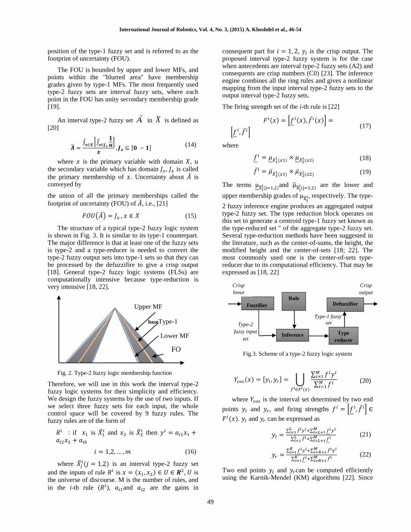
The structure of a typical type-2 fuzzy logic system is shown in Fig. 3. It is similar to its type-1 counterpart. The major difference is that at least one of the fuzzy sets is type-2 and a type-reducer is needed to convert the type-2 fuzzy output sets into type-1 sets so that they can be processed by the defuzzifire to give a crisp output [18]. General type-2 fuzzy logic systems (FLSs) are computationally intensive because type-reduction is very intensive [18, 22].
Fig. 2. Type-2 fuzzy logic membership function
Therefore, we will use in this work the interval type-2 fuzzy logic systems for their simplicity and efficiency. We design the fuzzy systems by the use of two inputs. If we select three fuzzy sets for each input, the whole control space will be covered by 9 fuzzy rules. The fuzzy rules are of the form of
𝑅𝑖 : if 𝑥1 is �̃�1𝑖 and 𝑥2 is �̃�2
𝑖 then 𝑦𝑖 = 𝑎𝑖1𝑥1 +𝑎𝑖2𝑥2 + 𝑎𝑖0
𝑖 = 1,2, … , 𝑚 (16)
where �̃�𝑗𝑖(𝑗 = 1,2) is an interval type-2 fuzzy set
and the inputs of rule 𝑅𝑖 is 𝑥 = (𝑥1, 𝑥2) ∈ 𝑈 ∈ 𝑹2, 𝑈 is the universe of discourse. M is the number of rules, and
in the i-th rule (𝑅𝑖), 𝑎𝑖1and 𝑎𝑖2 are the gains in
consequent part for 𝑖 = 1, 2, 𝑦𝑖 is the crisp output. The proposed interval type-2 fuzzy system is for the case when antecedents are interval type-2 fuzzy sets (A2) and consequents are crisp numbers (C0) [23]. The inference engine combines all the ring rules and gives a nonlinear mapping from the input interval type-2 fuzzy sets to the output interval type-2 fuzzy sets.
The firing strength set of the i-th rule is [22]
𝐹𝑖(𝑥) = [𝑓𝑖(𝑥), 𝑓̅𝑖(𝑥)] =
[𝑓 𝑖, 𝑓̅𝑖] (17)
where
𝑓𝑖 = 𝜇�̃�1𝑖 (𝑥1) × 𝜇�̃�2
𝑖 (𝑥2) (18)
𝑓̅𝑖 = �̅��̃�1
𝑖 (𝑥1)× �̅�
�̃�2𝑖 (𝑥2)
(19)
The terms μX̅j
i(j=1,2)and μ̅
X̅ji(j=1,2)
are the lower and
upper membership grades of μX̅j
i, respectively. The type-
2 fuzzy inference engine produces an aggregated output type-2 fuzzy set. The type reduction block operates on this set to generate a centroid type-1 fuzzy set known as the type-reduced set " of the aggregate type-2 fuzzy set. Several type-reduction methods have been suggested in the literature, such as the center-of-sums, the height, the modified height and the center-of-sets [18; 22]. The most commonly used one is the center-of-sets type-reducer due to its computational efficiency. That may be expressed as [18, 22]
Fig.3. Scheme of a type-2 fuzzy logic system
𝑌𝑐𝑜𝑠(𝑥) = [𝑦𝑙 , 𝑦𝑟] = ⋃∑ 𝑓𝑖𝑦𝑖𝑀
𝑖=1
∑ 𝑓𝑖𝑀𝑖=1
𝑓𝑖∈𝐹𝑖(𝑥)
(20)
where 𝑌𝑐𝑜𝑠 is the interval set determined by two end
points 𝑦𝑙 and 𝑦𝑟, and firing strengths 𝑓𝑖 = [𝑓𝑖 , 𝑓̅𝑖] ∈
𝐹𝑖(𝑥). 𝑦𝑙 and 𝑦𝑟 can be expressed as
𝑦𝑙 =∑ 𝑓̅𝑖𝑦𝑖+∑ 𝑓𝑖𝑦𝑖𝑀
𝑖=𝐿+1𝐿𝑖=1
∑ 𝑓̅𝑖+∑ 𝑓𝑖𝑀𝑖=𝐿+1
𝐿𝑖=1
(21)
𝑦𝑟 =∑ 𝑓𝑖𝑦𝑖+∑ 𝑓̅𝑖𝑦𝑖𝑀
𝑖=𝑅+1𝑅𝑖=1
∑ 𝑓𝑖+∑ 𝑓̅𝑖𝑀𝑖=𝑅+1
𝑅𝑖=1
(22)
Two end points 𝑦𝑙 and 𝑦𝑟can be computed efficiently using the Karnik-Mendel (KM) algorithms [22]. Since
Fuzzifier
Rule
Crisp
Input
Type-2
fuzzy input
set
Crisp
output
Type-1 fuzzy
set
Type
reducer Inference
Defuzzifier
baseType-1
MF
Upper MF
Lower MF
FO
U
International Journal of Robotics, Vol. 4, No. 3, (2015) A. Khoshdel et al., 46-54
50
the type- reduced set is an interval type-1 set, the defuzzifire output is [18]
𝑦(𝑥) = 0.5(𝑦𝑙 + 𝑦𝑟) (23)
4. Control strategy
An impedance rule is proposed as
(24) 𝑫𝒅(𝒕)(𝒒�̇� − �̇�) + 𝑲𝒅(𝒕)(𝒒𝒅 − 𝒒) = 𝝉𝒉
where 𝑫𝒅(𝒕) and 𝑲𝒅(𝒕) are the diagonal matrices, which include the desired impedance parameters that regulate by IT2FL systems. From (24), we have
(25) 𝒒�̇� + 𝑫𝒅−𝟏(𝒕)𝑲𝒅(𝒕)(𝒒𝒅 − 𝒒) + 𝑫𝒅
−𝟏(𝒕)𝝉𝒉
= �̇�
An impedance controller which establishes the impedance rule (14) is proposed as
(26) 𝑹𝑰𝒂 + 𝑳�̇�𝒂 + 𝑲(𝒒�̇� + 𝑫𝒅−𝟏𝑲𝒅(𝒕)(𝒒𝒅 − 𝒒)
+𝑫𝒅−𝟏(𝒕)𝝉𝒉) = 𝑽
The closed loop system is formed by substituting the control law (16) into the system (9) as
𝑹𝑰𝒂 + 𝑳�̇�𝒂 + 𝑲(𝒒�̇� + 𝑫𝒅−𝟏(𝒕)𝑲𝒅(𝒕)(𝒒𝒅
− 𝒒) + 𝑫𝒅−𝟏(𝒕) 𝝉𝒉)
= 𝑹𝑰𝒂 + 𝑳�̇�𝒂 + 𝑲�̇�
(27)
We design IT2FL system to determined impedance parameters adaptively, we consider the 𝑿𝟏𝑲 = 𝑭𝒅 − 𝑭𝒉 and 𝑿𝟐𝑲 = 𝒆 as inputs. Where 𝑒 is a position error and defined as 𝒆 = 𝑿𝒅 − 𝑿. The IT2FL takes these two
inputs and provides an impedance parameters dK .
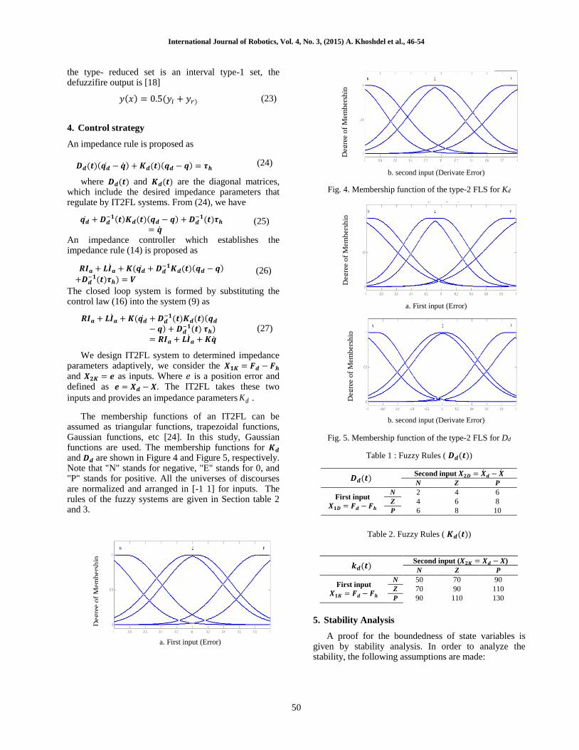
The membership functions of an IT2FL can be assumed as triangular functions, trapezoidal functions, Gaussian functions, etc [24]. In this study, Gaussian functions are used. The membership functions for 𝑲𝒅 and 𝑫𝒅 are shown in Figure 4 and Figure 5, respectively. Note that "N" stands for negative, "E" stands for 0, and "P" stands for positive. All the universes of discourses are normalized and arranged in [-1 1] for inputs. The rules of the fuzzy systems are given in Section table 2 and 3.
a. First input (Error)
b. second input (Derivate Error)
Fig. 4. Membership function of the type-2 FLS for Kd
a. First input (Error)
b. second input (Derivate Error)
Fig. 5. Membership function of the type-2 FLS for Dd
Table 1 : Fuzzy Rules ( 𝑫𝒅(𝒕))
𝑫𝒅(𝒕) Second input 𝑿𝟐𝑫 = �̇�𝒅 − �̇�
N Z P
First input 𝑿𝟏𝑫 = 𝑭𝒅 − 𝑭𝒉
N 2 4 6
Z 4 6 8
P 6 8 10
Table 2. Fuzzy Rules ( 𝑲𝒅(𝒕))
𝒌𝒅(𝒕) Second input (𝑿𝟐𝑲 = 𝑿𝒅 − 𝑿)
N Z P
First input
𝑿𝟏𝑲 = 𝑭𝒅 − 𝑭𝒉
N 50 70 90
Z 70 90 110
P 90 110 130
5. Stability Analysis
A proof for the boundedness of state variables is given by stability analysis. In order to analyze the stability, the following assumptions are made:
Deg
ree
of
Mem
ber
ship
D
egre
e o
f M
emb
ersh
ip
Deg
ree
of
Mem
ber
ship
Deg
ree
of
Mem
ber
ship
International Journal of Robotics, Vol. 4, No. 3, (2015) A. Khoshdel et al., 46-54
51
𝑫𝒅(𝒕)(𝒒�̇� − �̇�) + 𝑲𝒅(𝒒𝒅 − 𝒒) = 𝝉𝒉 (28)
Assumption 1 The desired trajectory in the joint-space 𝐪𝐝 must be smooth in the sense that 𝒒𝒅 and its derivatives up to a necessary order are available and all uniformly bounded [22]. Equation (28) shows a linear second order system with a bounded input 𝝉𝒉. In (28) the suggested matrices 𝑫𝒅(𝒕) and 𝑲𝒅(𝒕) are positive diagonal matrices. Therefore, the linear system (28) is stable based on the Ruth-Hurwitz criteria. Because the input 𝝉𝒉 is bounded as a consequence
Result 1: 𝒒𝒅 − 𝒒 and 𝒒�̇� − �̇� are bounded.
In addition, Assumption 1 states that 𝒒𝒅 and 𝒒�̇� are bounded. Thus, using Assumption 1 and Result 1 yields to Result 3: The variables 𝒒 and �̇� are bounded. In (3), the boundedness of 𝒒, �̇� and 𝝉𝒉 yields to Result 4: The joint torque vector 𝝉𝒓 is bounded. In (7), vectors of �̇�, �̈� and 𝝉𝒓 are bounded and matrices 𝐽
𝑚, 𝐵𝑚 and 𝑟 are constant. Thus,
Result 5: The motor torque vector 𝝉𝒎 is bounded.
From (10), it can be written that 𝑰𝒂 = 𝑲𝒎−𝟏 𝝉𝒎. 𝐾𝑚 is a
constant matrix and 𝝉𝒎 is bounded in Result 5. Therefore, Result 6: The motor current vector 𝑰𝒂 is bounded. The robotic system is stable since all system states 𝒒, �̇� and 𝑰𝒂 are bounded.
6. Simulation Results
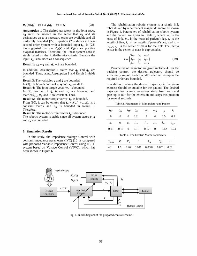
In this study, the Impedance Voltage Control with constant impedance parameters (IVC) [10] is compared with proposed Variable Impedance Control using IT2FL system based on Voltage Control (VIVC), which has been shown in Figure 6.
The rehabilitation robotic system is a single link robot driven by a permanent magnet dc motor as shown in Figure 1. Parameters of rehabilitation robotic system and the patient are given in Table 3, where 𝑚𝑟 is the mass of link, 𝑚ℎ is the mass of patient’s leg, 𝑙𝑟 is the length of link, 𝑙𝑝 is the length of patient’s leg, and 𝑟𝑐 =
[𝑥𝑐 , 𝑦𝑐 , 𝑧𝑐] is the center of mass for the link. The inertia tensor in the center of mass is expressed as
𝐼 = (
𝐼𝑥𝑥 𝐼𝑥𝑦 𝐼𝑥𝑧
𝐼𝑦𝑥 𝐼𝑦𝑦 𝐼𝑦𝑧
𝐼𝑧𝑥 𝐼𝑧𝑦 𝐼𝑧𝑧
) (29)
Parameters of the motor are given in Table 4. For the tracking control, the desired trajectory should be sufficiently smooth such that all its derivatives up to the required order are bounded.
In addition, tracking the desired trajectory in the given exercise should be suitable for the patient. The desired trajectory for isotonic exercises starts from zero and goes up to 80° for the extension and stays this position for several seconds.
Table 3. Parameters of Manipulator and Patient
𝐼𝑦𝑧
𝐼𝑧𝑥 𝐼𝑧𝑦 𝐼𝑧𝑧 𝑚𝑟 𝑚ℎ 𝑙ℎ 𝑙𝑟
0 0 0 0.91 2 4 0.5 0.5
𝑥𝑐 𝑦𝑐 𝑧𝑐 𝐼𝑥𝑥 𝐼𝑥𝑦 𝐼𝑥𝑧 𝐼𝑦𝑥
𝐼𝑦𝑦
0.09 -0.16 0 0.91 -0.12 0 -0.12 0.23
Table 4. The Electric Motor Parameters
𝑉𝑚𝑎𝑥 𝑅 𝐾𝑏 𝐿 𝐽𝑚 𝐵𝑚 𝑟
40 1.6 0.26 0.001 0.0002 0.001 0.02
Fig. 6. Block diagram of the proposed control scheme
𝑒𝑥 , �̇�𝑥
Impedance
Control Robot Patient
𝑥,𝑥
,𝑥 Human Torque
V 𝑥, �̇�, �̈�
IT2FL
system 𝑲𝒅(𝒕)
𝑫𝒅(𝒕)
Physiotherapy
Desired
Trajectory
𝑒𝑓
I
International Journal of Robotics, Vol. 4, No. 3, (2015) A. Khoshdel et al., 46-54
52
6.1. Isometric exercise
The aim of this exercise is that the specified resistance force applied to the patient while the limb angle not change. The force is determined individually for each patient by physiotherapist. In this type of exercise limb move to the desired angle, without applied any resistance force to the patient, after that the desired force applied to the patient and he or she try to not be changed the angle of limb.
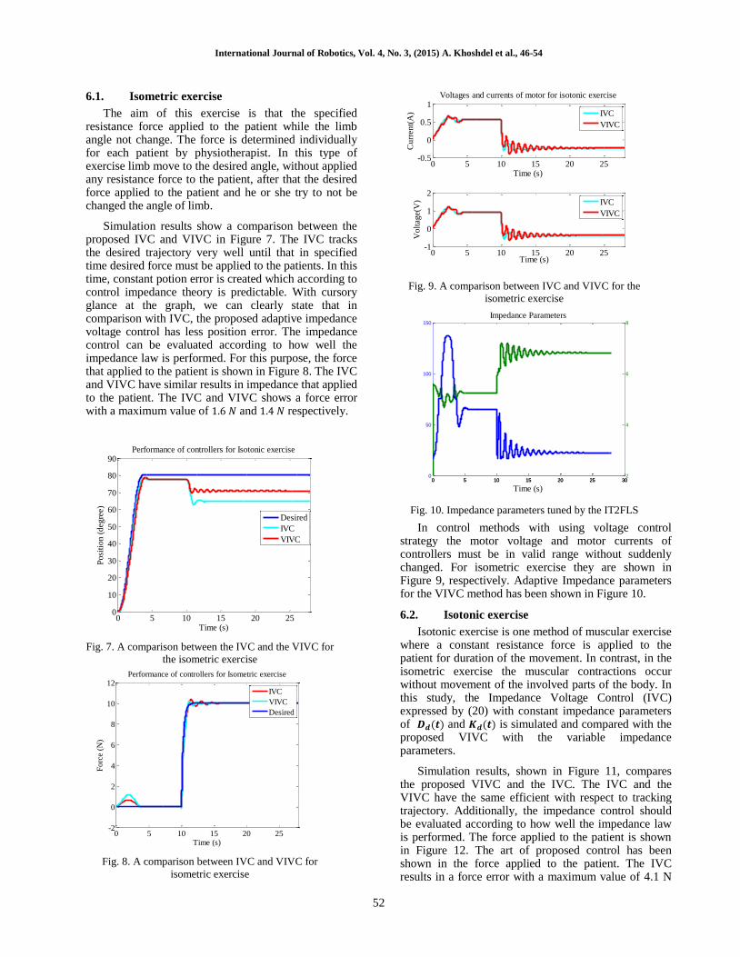
Simulation results show a comparison between the proposed IVC and VIVC in Figure 7. The IVC tracks the desired trajectory very well until that in specified time desired force must be applied to the patients. In this time, constant potion error is created which according to control impedance theory is predictable. With cursory glance at the graph, we can clearly state that in comparison with IVC, the proposed adaptive impedance voltage control has less position error. The impedance control can be evaluated according to how well the impedance law is performed. For this purpose, the force that applied to the patient is shown in Figure 8. The IVC and VIVC have similar results in impedance that applied to the patient. The IVC and VIVC shows a force error with a maximum value of 1.6 𝑁 and 1.4 𝑁 respectively.
Fig. 7. A comparison between the IVC and the VIVC for
the isometric exercise
Fig. 8. A comparison between IVC and VIVC for
isometric exercise
Fig. 9. A comparison between IVC and VIVC for the
isometric exercise
Fig. 10. Impedance parameters tuned by the IT2FLS
In control methods with using voltage control strategy the motor voltage and motor currents of controllers must be in valid range without suddenly changed. For isometric exercise they are shown in Figure 9, respectively. Adaptive Impedance parameters for the VIVC method has been shown in Figure 10.
6.2. Isotonic exercise
Isotonic exercise is one method of muscular exercise where a constant resistance force is applied to the patient for duration of the movement. In contrast, in the isometric exercise the muscular contractions occur without movement of the involved parts of the body. In this study, the Impedance Voltage Control (IVC) expressed by (20) with constant impedance parameters of 𝑫𝒅(𝒕) and 𝑲𝒅(𝒕) is simulated and compared with the proposed VIVC with the variable impedance parameters.
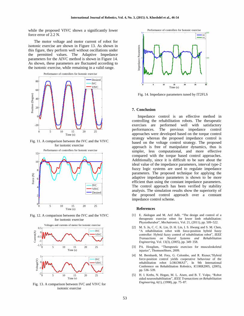
Simulation results, shown in Figure 11, compares the proposed VIVC and the IVC. The IVC and the VIVC have the same efficient with respect to tracking trajectory. Additionally, the impedance control should be evaluated according to how well the impedance law is performed. The force applied to the patient is shown in Figure 12. The art of proposed control has been shown in the force applied to the patient. The IVC results in a force error with a maximum value of 4.1 N
0 5 10 15 20 250
10
20
30
40
50
60
70
80
90
Time (s)
Posi
tion (
deg
ree)
Performance of controllers for Isotonic exercise
Desired
IVC
VIVC
0 5 10 15 20 25-2
0
2
4
6
8
10
12
Time (s)
Forc
e (N
)
Performance of controllers for Isometric exercise
IVC
VIVC
Desired
0 5 10 15 20 25-0.5
0
0.5
1
Time (s)
Curr
ent(
A)
Voltages and currents of motor for isotonic exercise
0 5 10 15 20 25-1
0
1
2
Time (s)
Volt
age(
V)
IVC
VIVC
IVC
VIVC
0 5 10 15 20 25 300
50
100
150
Time (s)
Impedance Parameters
0 5 10 15 20 25 302
4
6
8
International Journal of Robotics, Vol. 4, No. 3, (2015) A. Khoshdel et al., 46-54
53
while the proposed VIVC shows a significantly lower force error of 2.2 N.
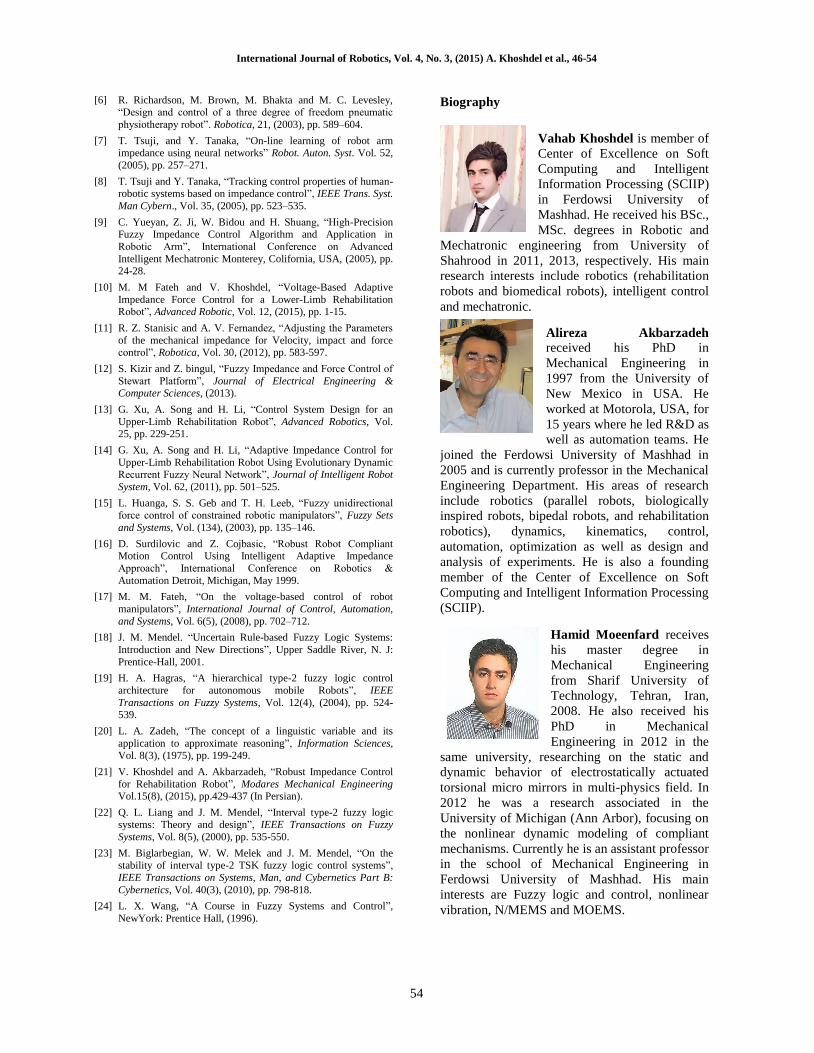
The motor voltage and motor current of robot for isotonic exercise are shown in Figure 13. As shown in this figure, they perform well without oscillations under the permitted values. The Adaptive Impedance parameters for the AIVC method is shown in Figure 14. As shown, these parameters are fluctuated according to the isotonic exercise, while remaining in a valid range.
Fig. 11. A comparison between the IVC and the VIVC
for isotonic exercise
Fig. 12. A comparison between the IVC and the VIVC
for isotonic exercise
Fig. 13. A comparison between IVC and VIVC for
isotonic exercise
Fig. 14. Impedance parameters tuned by IT2FLS
7. Conclusion
Impedance control is an effective method in controlling the rehabilitation robots. The therapeutic exercises are performed well with satisfactory performances. The previous impedance control approaches were developed based on the torque control strategy whereas the proposed impedance control is based on the voltage control strategy. The proposed approach is free of manipulator dynamics, thus is simpler, less computational, and more effective compared with the torque based control approaches. Additionally, since it is difficult to be sure about the ideal value of the impedance parameters, interval type-2 fuzzy logic systems are used to regulate impedance parameters. The proposed technique for applying the adaptive impedance parameters is shown to be more efficient than using the constant impedance parameters. The control approach has been verified by stability analysis. The simulation results show the superiority of the proposed control approach over a constant impedance control scheme.
References
[1] E. Akdogan and M. Arif Adli. “The design and control of a therapeutic exercise robot for lower limb rehabilitation:
Physiotherabot”, Mechatronics, Vol. 21, (2011), pp. 509–522.
[2] M. S. Ju, C. C. K. Lin, D. H. Lin, I. S. Hwang and S. M. Chen, “A rehabilitation robot with force-position hybrid fuzzy
controller: Hybrid fuzzy control of rehabilitation robot”, IEEE
Transactions on Neural Systems and Rehabilitation Engineering, Vol. 13(3), (2005), pp. 349–358.
[3] PA. Houglum, “Therapeutic exercises for musculoskeletal
injuries”, ThomsonShore, 2009.
[4] M. Bernhardt, M. Frey, G. Colombo, and R. Riener,“Hybrid
force-position control yields cooperative behaviour of the
rehabilitation robot LOKOMAT”, In 9th International Conference on Rehabilitation Robotics, ICORR2005, (2005),
pp. 536–539.
[5] H. I. Krebs, N. Hogan, M. L. Aisen, and B. T. Volpe, “Robot aided neurorehabilitation”, IEEE Transactions on Rehabilitation
Engineering, 6(1), (1998), pp. 75–87.
0 5 10 15 20 25
-20
0
20
40
60
80
Time (s)
Posi
tion (
Deg
ree)
Performance of controllers for Isotonic exercise
Desierd
IVC
VIVC
0 5 10 15 20 250
2
4
6
8
10
12
Time (s)
Forc
e (N
)
Performance of controllers for Isotonic exercise
IVC
VIVC
Desired
0 5 10 15 20 25-1.5
-1
-0.5
0
0.5
Time (s)
Curr
ent(
A)
Voltages and currents of motor for isotonic exercise
0 5 10 15 20 25-2
-1
0
1
Time (s)
Volt
age(
V)
IVC
VIVC
IVC
VIVC
0 5 10 15 20 25 301
2
3
Time (s)
Imped
ance
Par
amet
ers
Performance of controllers for Isotonic exercise
0 5 10 15 20 25 300
100
200
Dd
Kd
International Journal of Robotics, Vol. 4, No. 3, (2015) A. Khoshdel et al., 46-54
54
[6] R. Richardson, M. Brown, M. Bhakta and M. C. Levesley,
“Design and control of a three degree of freedom pneumatic
physiotherapy robot”. Robotica, 21, (2003), pp. 589–604.
[7] T. Tsuji, and Y. Tanaka, “On-line learning of robot arm impedance using neural networks” Robot. Auton. Syst. Vol. 52,
(2005), pp. 257–271.
[8] T. Tsuji and Y. Tanaka, “Tracking control properties of human-robotic systems based on impedance control”, IEEE Trans. Syst.
Man Cybern., Vol. 35, (2005), pp. 523–535.
[9] C. Yueyan, Z. Ji, W. Bidou and H. Shuang, “High-Precision Fuzzy Impedance Control Algorithm and Application in
Robotic Arm”, International Conference on Advanced
Intelligent Mechatronic Monterey, Colifornia, USA, (2005), pp. 24-28.
[10] M. M Fateh and V. Khoshdel, “Voltage-Based Adaptive
Impedance Force Control for a Lower-Limb Rehabilitation Robot”, Advanced Robotic, Vol. 12, (2015), pp. 1-15.
[11] R. Z. Stanisic and A. V. Fernandez, “Adjusting the Parameters
of the mechanical impedance for Velocity, impact and force control”, Robotica, Vol. 30, (2012), pp. 583-597.
[12] S. Kizir and Z. bingul, “Fuzzy Impedance and Force Control of
Stewart Platform”, Journal of Electrical Engineering & Computer Sciences, (2013).
[13] G. Xu, A. Song and H. Li, “Control System Design for an
Upper-Limb Rehabilitation Robot”, Advanced Robotics, Vol. 25, pp. 229-251.
[14] G. Xu, A. Song and H. Li, “Adaptive Impedance Control for
Upper-Limb Rehabilitation Robot Using Evolutionary Dynamic Recurrent Fuzzy Neural Network”, Journal of Intelligent Robot
System, Vol. 62, (2011), pp. 501–525.
[15] L. Huanga, S. S. Geb and T. H. Leeb, “Fuzzy unidirectional force control of constrained robotic manipulators”, Fuzzy Sets
and Systems, Vol. (134), (2003), pp. 135–146.
[16] D. Surdilovic and Z. Cojbasic, “Robust Robot Compliant Motion Control Using Intelligent Adaptive Impedance
Approach”, International Conference on Robotics &
Automation Detroit, Michigan, May 1999.
[17] M. M. Fateh, “On the voltage-based control of robot
manipulators”, International Journal of Control, Automation,
and Systems, Vol. 6(5), (2008), pp. 702–712.
[18] J. M. Mendel. “Uncertain Rule-based Fuzzy Logic Systems:
Introduction and New Directions”, Upper Saddle River, N. J:
Prentice-Hall, 2001.
[19] H. A. Hagras, “A hierarchical type-2 fuzzy logic control
architecture for autonomous mobile Robots”, IEEE
Transactions on Fuzzy Systems, Vol. 12(4), (2004), pp. 524-539.
[20] L. A. Zadeh, “The concept of a linguistic variable and its
application to approximate reasoning”, Information Sciences, Vol. 8(3), (1975), pp. 199-249.
[21] V. Khoshdel and A. Akbarzadeh, “Robust Impedance Control
for Rehabilitation Robot”, Modares Mechanical Engineering Vol.15(8), (2015), pp.429-437 (In Persian).
[22] Q. L. Liang and J. M. Mendel, “Interval type-2 fuzzy logic systems: Theory and design”, IEEE Transactions on Fuzzy
Systems, Vol. 8(5), (2000), pp. 535-550.
[23] M. Biglarbegian, W. W. Melek and J. M. Mendel, “On the stability of interval type-2 TSK fuzzy logic control systems”,
IEEE Transactions on Systems, Man, and Cybernetics Part B:
Cybernetics, Vol. 40(3), (2010), pp. 798-818.
[24] L. X. Wang, “A Course in Fuzzy Systems and Control”,
NewYork: Prentice Hall, (1996).
Biography
Vahab Khoshdel is member of
Center of Excellence on Soft
Computing and Intelligent
Information Processing (SCIIP)
in Ferdowsi University of
Mashhad. He received his BSc.,
MSc. degrees in Robotic and
Mechatronic engineering from University of
Shahrood in 2011, 2013, respectively. His main
research interests include robotics (rehabilitation
robots and biomedical robots), intelligent control
and mechatronic.
Alireza Akbarzadeh received his PhD in
Mechanical Engineering in
1997 from the University of
New Mexico in USA. He
worked at Motorola, USA, for
15 years where he led R&D as
well as automation teams. He
joined the Ferdowsi University of Mashhad in
2005 and is currently professor in the Mechanical
Engineering Department. His areas of research
include robotics (parallel robots, biologically
inspired robots, bipedal robots, and rehabilitation
robotics), dynamics, kinematics, control,
automation, optimization as well as design and
analysis of experiments. He is also a founding
member of the Center of Excellence on Soft
Computing and Intelligent Information Processing
(SCIIP).
Hamid Moeenfard receives
his master degree in
Mechanical Engineering
from Sharif University of
Technology, Tehran, Iran,
2008. He also received his
PhD in Mechanical
Engineering in 2012 in the
same university, researching on the static and
dynamic behavior of electrostatically actuated
torsional micro mirrors in multi-physics field. In
2012 he was a research associated in the
University of Michigan (Ann Arbor), focusing on
the nonlinear dynamic modeling of compliant
mechanisms. Currently he is an assistant professor
in the school of Mechanical Engineering in
Ferdowsi University of Mashhad. His main
interests are Fuzzy logic and control, nonlinear
vibration, N/MEMS and MOEMS.